EP3208599B1 - Method for using a submersible probe, as a function of a particle concentration - Google Patents
Method for using a submersible probe, as a function of a particle concentration Download PDFInfo
- Publication number
- EP3208599B1 EP3208599B1 EP17165937.8A EP17165937A EP3208599B1 EP 3208599 B1 EP3208599 B1 EP 3208599B1 EP 17165937 A EP17165937 A EP 17165937A EP 3208599 B1 EP3208599 B1 EP 3208599B1
- Authority
- EP
- European Patent Office
- Prior art keywords
- transparent window
- diffraction
- cell
- distance
- elementary
- Prior art date
- Legal status (The legal status is an assumption and is not a legal conclusion. Google has not performed a legal analysis and makes no representation as to the accuracy of the status listed.)
- Active
Links
- 239000000523 sample Substances 0.000 title claims description 79
- 238000000034 method Methods 0.000 title claims description 42
- 239000002245 particle Substances 0.000 title claims description 23
- 239000006193 liquid solution Substances 0.000 claims description 26
- 239000011159 matrix material Substances 0.000 claims description 24
- 230000001427 coherent effect Effects 0.000 claims description 3
- 238000003384 imaging method Methods 0.000 description 10
- 230000005855 radiation Effects 0.000 description 5
- 230000008901 benefit Effects 0.000 description 3
- 238000004113 cell culture Methods 0.000 description 3
- 239000003550 marker Substances 0.000 description 3
- 230000003287 optical effect Effects 0.000 description 3
- 239000000126 substance Substances 0.000 description 3
- 241001080024 Telles Species 0.000 description 2
- 238000001311 chemical methods and process Methods 0.000 description 2
- 238000001514 detection method Methods 0.000 description 2
- 230000001747 exhibiting effect Effects 0.000 description 2
- 239000007850 fluorescent dye Substances 0.000 description 2
- 230000004048 modification Effects 0.000 description 2
- 238000012986 modification Methods 0.000 description 2
- 230000008569 process Effects 0.000 description 2
- 241000446313 Lamella Species 0.000 description 1
- 206010028980 Neoplasm Diseases 0.000 description 1
- 238000010521 absorption reaction Methods 0.000 description 1
- 238000013019 agitation Methods 0.000 description 1
- QVGXLLKOCUKJST-UHFFFAOYSA-N atomic oxygen Chemical compound [O] QVGXLLKOCUKJST-UHFFFAOYSA-N 0.000 description 1
- 239000013060 biological fluid Substances 0.000 description 1
- 230000005540 biological transmission Effects 0.000 description 1
- 239000008280 blood Substances 0.000 description 1
- 210000004369 blood Anatomy 0.000 description 1
- BQRGNLJZBFXNCZ-UHFFFAOYSA-N calcein am Chemical compound O1C(=O)C2=CC=CC=C2C21C1=CC(CN(CC(=O)OCOC(C)=O)CC(=O)OCOC(C)=O)=C(OC(C)=O)C=C1OC1=C2C=C(CN(CC(=O)OCOC(C)=O)CC(=O)OCOC(=O)C)C(OC(C)=O)=C1 BQRGNLJZBFXNCZ-UHFFFAOYSA-N 0.000 description 1
- 201000011510 cancer Diseases 0.000 description 1
- 230000000295 complement effect Effects 0.000 description 1
- 238000004163 cytometry Methods 0.000 description 1
- 238000000151 deposition Methods 0.000 description 1
- 238000009792 diffusion process Methods 0.000 description 1
- 230000000694 effects Effects 0.000 description 1
- 230000005670 electromagnetic radiation Effects 0.000 description 1
- 238000000295 emission spectrum Methods 0.000 description 1
- 238000001914 filtration Methods 0.000 description 1
- 238000000799 fluorescence microscopy Methods 0.000 description 1
- 230000006870 function Effects 0.000 description 1
- 238000001093 holography Methods 0.000 description 1
- XMBWDFGMSWQBCA-UHFFFAOYSA-N hydrogen iodide Chemical compound I XMBWDFGMSWQBCA-UHFFFAOYSA-N 0.000 description 1
- 238000011065 in-situ storage Methods 0.000 description 1
- 238000002372 labelling Methods 0.000 description 1
- 239000007788 liquid Substances 0.000 description 1
- 239000000463 material Substances 0.000 description 1
- 238000005259 measurement Methods 0.000 description 1
- 229910044991 metal oxide Inorganic materials 0.000 description 1
- 150000004706 metal oxides Chemical class 0.000 description 1
- 229910052760 oxygen Inorganic materials 0.000 description 1
- 239000001301 oxygen Substances 0.000 description 1
- 230000001681 protective effect Effects 0.000 description 1
- 230000004044 response Effects 0.000 description 1
- 230000000630 rising effect Effects 0.000 description 1
- 239000004065 semiconductor Substances 0.000 description 1
- XLYOFNOQVPJJNP-UHFFFAOYSA-N water Substances O XLYOFNOQVPJJNP-UHFFFAOYSA-N 0.000 description 1
Images


Classifications
-
- C—CHEMISTRY; METALLURGY
- C12—BIOCHEMISTRY; BEER; SPIRITS; WINE; VINEGAR; MICROBIOLOGY; ENZYMOLOGY; MUTATION OR GENETIC ENGINEERING
- C12M—APPARATUS FOR ENZYMOLOGY OR MICROBIOLOGY; APPARATUS FOR CULTURING MICROORGANISMS FOR PRODUCING BIOMASS, FOR GROWING CELLS OR FOR OBTAINING FERMENTATION OR METABOLIC PRODUCTS, i.e. BIOREACTORS OR FERMENTERS
- C12M47/00—Means for after-treatment of the produced biomass or of the fermentation or metabolic products, e.g. storage of biomass
- C12M47/04—Cell isolation or sorting
-
- C—CHEMISTRY; METALLURGY
- C12—BIOCHEMISTRY; BEER; SPIRITS; WINE; VINEGAR; MICROBIOLOGY; ENZYMOLOGY; MUTATION OR GENETIC ENGINEERING
- C12M—APPARATUS FOR ENZYMOLOGY OR MICROBIOLOGY; APPARATUS FOR CULTURING MICROORGANISMS FOR PRODUCING BIOMASS, FOR GROWING CELLS OR FOR OBTAINING FERMENTATION OR METABOLIC PRODUCTS, i.e. BIOREACTORS OR FERMENTERS
- C12M23/00—Constructional details, e.g. recesses, hinges
- C12M23/22—Transparent or translucent parts
-
- C—CHEMISTRY; METALLURGY
- C12—BIOCHEMISTRY; BEER; SPIRITS; WINE; VINEGAR; MICROBIOLOGY; ENZYMOLOGY; MUTATION OR GENETIC ENGINEERING
- C12M—APPARATUS FOR ENZYMOLOGY OR MICROBIOLOGY; APPARATUS FOR CULTURING MICROORGANISMS FOR PRODUCING BIOMASS, FOR GROWING CELLS OR FOR OBTAINING FERMENTATION OR METABOLIC PRODUCTS, i.e. BIOREACTORS OR FERMENTERS
- C12M31/00—Means for providing, directing, scattering or concentrating light
-
- G—PHYSICS
- G01—MEASURING; TESTING
- G01N—INVESTIGATING OR ANALYSING MATERIALS BY DETERMINING THEIR CHEMICAL OR PHYSICAL PROPERTIES
- G01N15/00—Investigating characteristics of particles; Investigating permeability, pore-volume or surface-area of porous materials
- G01N15/10—Investigating individual particles
- G01N15/14—Optical investigation techniques, e.g. flow cytometry
- G01N15/1429—Signal processing
- G01N15/1433—Signal processing using image recognition
-
- G—PHYSICS
- G01—MEASURING; TESTING
- G01N—INVESTIGATING OR ANALYSING MATERIALS BY DETERMINING THEIR CHEMICAL OR PHYSICAL PROPERTIES
- G01N21/00—Investigating or analysing materials by the use of optical means, i.e. using sub-millimetre waves, infrared, visible or ultraviolet light
- G01N21/17—Systems in which incident light is modified in accordance with the properties of the material investigated
- G01N21/41—Refractivity; Phase-affecting properties, e.g. optical path length
- G01N21/45—Refractivity; Phase-affecting properties, e.g. optical path length using interferometric methods; using Schlieren methods
- G01N21/453—Holographic interferometry
-
- G—PHYSICS
- G01—MEASURING; TESTING
- G01N—INVESTIGATING OR ANALYSING MATERIALS BY DETERMINING THEIR CHEMICAL OR PHYSICAL PROPERTIES
- G01N21/00—Investigating or analysing materials by the use of optical means, i.e. using sub-millimetre waves, infrared, visible or ultraviolet light
- G01N21/17—Systems in which incident light is modified in accordance with the properties of the material investigated
- G01N21/47—Scattering, i.e. diffuse reflection
- G01N21/4788—Diffraction
-
- G—PHYSICS
- G01—MEASURING; TESTING
- G01N—INVESTIGATING OR ANALYSING MATERIALS BY DETERMINING THEIR CHEMICAL OR PHYSICAL PROPERTIES
- G01N21/00—Investigating or analysing materials by the use of optical means, i.e. using sub-millimetre waves, infrared, visible or ultraviolet light
- G01N21/17—Systems in which incident light is modified in accordance with the properties of the material investigated
- G01N21/47—Scattering, i.e. diffuse reflection
- G01N21/49—Scattering, i.e. diffuse reflection within a body or fluid
- G01N21/51—Scattering, i.e. diffuse reflection within a body or fluid inside a container, e.g. in an ampoule
-
- G—PHYSICS
- G01—MEASURING; TESTING
- G01N—INVESTIGATING OR ANALYSING MATERIALS BY DETERMINING THEIR CHEMICAL OR PHYSICAL PROPERTIES
- G01N33/00—Investigating or analysing materials by specific methods not covered by groups G01N1/00 - G01N31/00
- G01N33/48—Biological material, e.g. blood, urine; Haemocytometers
- G01N33/483—Physical analysis of biological material
- G01N33/4833—Physical analysis of biological material of solid biological material, e.g. tissue samples, cell cultures
-
- G—PHYSICS
- G03—PHOTOGRAPHY; CINEMATOGRAPHY; ANALOGOUS TECHNIQUES USING WAVES OTHER THAN OPTICAL WAVES; ELECTROGRAPHY; HOLOGRAPHY
- G03H—HOLOGRAPHIC PROCESSES OR APPARATUS
- G03H1/00—Holographic processes or apparatus using light, infrared or ultraviolet waves for obtaining holograms or for obtaining an image from them; Details peculiar thereto
- G03H1/0005—Adaptation of holography to specific applications
-
- G—PHYSICS
- G03—PHOTOGRAPHY; CINEMATOGRAPHY; ANALOGOUS TECHNIQUES USING WAVES OTHER THAN OPTICAL WAVES; ELECTROGRAPHY; HOLOGRAPHY
- G03H—HOLOGRAPHIC PROCESSES OR APPARATUS
- G03H1/00—Holographic processes or apparatus using light, infrared or ultraviolet waves for obtaining holograms or for obtaining an image from them; Details peculiar thereto
- G03H1/04—Processes or apparatus for producing holograms
- G03H1/0443—Digital holography, i.e. recording holograms with digital recording means
-
- G—PHYSICS
- G03—PHOTOGRAPHY; CINEMATOGRAPHY; ANALOGOUS TECHNIQUES USING WAVES OTHER THAN OPTICAL WAVES; ELECTROGRAPHY; HOLOGRAPHY
- G03H—HOLOGRAPHIC PROCESSES OR APPARATUS
- G03H1/00—Holographic processes or apparatus using light, infrared or ultraviolet waves for obtaining holograms or for obtaining an image from them; Details peculiar thereto
- G03H1/04—Processes or apparatus for producing holograms
- G03H1/0465—Particular recording light; Beam shape or geometry
-
- G—PHYSICS
- G01—MEASURING; TESTING
- G01N—INVESTIGATING OR ANALYSING MATERIALS BY DETERMINING THEIR CHEMICAL OR PHYSICAL PROPERTIES
- G01N15/00—Investigating characteristics of particles; Investigating permeability, pore-volume or surface-area of porous materials
- G01N15/10—Investigating individual particles
- G01N15/14—Optical investigation techniques, e.g. flow cytometry
- G01N15/1434—Optical arrangements
- G01N15/1436—Optical arrangements the optical arrangement forming an integrated apparatus with the sample container, e.g. a flow cell
-
- G—PHYSICS
- G01—MEASURING; TESTING
- G01N—INVESTIGATING OR ANALYSING MATERIALS BY DETERMINING THEIR CHEMICAL OR PHYSICAL PROPERTIES
- G01N15/00—Investigating characteristics of particles; Investigating permeability, pore-volume or surface-area of porous materials
- G01N15/10—Investigating individual particles
- G01N2015/1006—Investigating individual particles for cytology
-
- G—PHYSICS
- G01—MEASURING; TESTING
- G01N—INVESTIGATING OR ANALYSING MATERIALS BY DETERMINING THEIR CHEMICAL OR PHYSICAL PROPERTIES
- G01N15/00—Investigating characteristics of particles; Investigating permeability, pore-volume or surface-area of porous materials
- G01N15/10—Investigating individual particles
- G01N15/14—Optical investigation techniques, e.g. flow cytometry
- G01N15/1434—Optical arrangements
- G01N2015/1454—Optical arrangements using phase shift or interference, e.g. for improving contrast
-
- G—PHYSICS
- G01—MEASURING; TESTING
- G01N—INVESTIGATING OR ANALYSING MATERIALS BY DETERMINING THEIR CHEMICAL OR PHYSICAL PROPERTIES
- G01N21/00—Investigating or analysing materials by the use of optical means, i.e. using sub-millimetre waves, infrared, visible or ultraviolet light
- G01N21/01—Arrangements or apparatus for facilitating the optical investigation
- G01N21/03—Cuvette constructions
- G01N2021/036—Cuvette constructions transformable, modifiable
-
- G—PHYSICS
- G01—MEASURING; TESTING
- G01N—INVESTIGATING OR ANALYSING MATERIALS BY DETERMINING THEIR CHEMICAL OR PHYSICAL PROPERTIES
- G01N21/00—Investigating or analysing materials by the use of optical means, i.e. using sub-millimetre waves, infrared, visible or ultraviolet light
- G01N21/84—Systems specially adapted for particular applications
- G01N21/85—Investigating moving fluids or granular solids
- G01N21/8507—Probe photometers, i.e. with optical measuring part dipped into fluid sample
-
- G—PHYSICS
- G03—PHOTOGRAPHY; CINEMATOGRAPHY; ANALOGOUS TECHNIQUES USING WAVES OTHER THAN OPTICAL WAVES; ELECTROGRAPHY; HOLOGRAPHY
- G03H—HOLOGRAPHIC PROCESSES OR APPARATUS
- G03H1/00—Holographic processes or apparatus using light, infrared or ultraviolet waves for obtaining holograms or for obtaining an image from them; Details peculiar thereto
- G03H1/0005—Adaptation of holography to specific applications
- G03H2001/0033—Adaptation of holography to specific applications in hologrammetry for measuring or analysing
-
- G—PHYSICS
- G03—PHOTOGRAPHY; CINEMATOGRAPHY; ANALOGOUS TECHNIQUES USING WAVES OTHER THAN OPTICAL WAVES; ELECTROGRAPHY; HOLOGRAPHY
- G03H—HOLOGRAPHIC PROCESSES OR APPARATUS
- G03H1/00—Holographic processes or apparatus using light, infrared or ultraviolet waves for obtaining holograms or for obtaining an image from them; Details peculiar thereto
- G03H1/04—Processes or apparatus for producing holograms
- G03H1/0443—Digital holography, i.e. recording holograms with digital recording means
- G03H2001/0447—In-line recording arrangement
-
- G—PHYSICS
- G03—PHOTOGRAPHY; CINEMATOGRAPHY; ANALOGOUS TECHNIQUES USING WAVES OTHER THAN OPTICAL WAVES; ELECTROGRAPHY; HOLOGRAPHY
- G03H—HOLOGRAPHIC PROCESSES OR APPARATUS
- G03H2222/00—Light sources or light beam properties
- G03H2222/34—Multiple light sources
Definitions
- the present invention relates to the use of an immersible probe as a function of a particle concentration.
- fluorescence microscopy methods are known. These methods use an optical microscope to visualize a sample, as well as a fluorescent marker which binds preferentially to a category of cells, among the two categories living cells and dead cells.
- the fluorescent label absorbs incident radiation at a first wavelength, and in response emits fluorescence radiation at a second wavelength.
- the cells fixed to the fluorescent marker are called “marked cells”. It can be seen that by illuminating a sample of cells marked with radiation at the first wavelength, it is possible to discriminate a living cell from a dead cell by identifying the cells emitting the fluorescence radiation at the second wavelength.
- cells exhibiting a color corresponding to the wavelength of the fluorescence radiation, and cells not exhibiting this color will be observed under the microscope.
- calcein AM As a fluorescent marker binding only to living cells.
- Proprium iodide is also known to bind only to dead cells.
- a disadvantage of these methods is that they are invasive: the cell sample is disturbed by the addition of the fluorescent label.
- the inventors propose below a method for discriminating a living cell from a dead cell, which does not have at least one of the drawbacks of the prior art.
- the present invention relates to a method of using an immersible probe, of particular interest in the context of this method for discriminating a living cell from a dead cell.
- a lensless imaging device 10 Such a device is known to those skilled in the art, who will easily be able to find the details of making such a device in the literature.
- a light source 11 emits a light beam 12 illuminating a sample 14.
- the light source is preferably spatially coherent.
- the light source can be a laser diode, or a light emitting diode (LED) followed by a filter hole.
- the filter hole improves the spatial coherence of the light beam emitted by the LED.
- the light source is also temporally coherent.
- an LED is used whose emission spectrum is centered on 450 nm, ie an emission in the blue.
- the peak width at 450 nm is 40 nm.
- the emission power of the LED is for example between 100 mW and 1 W.
- the LED is followed by a filtering hole with a diameter of 150 ⁇ m, placed directly in contact with the LED.
- Sample 14 is placed between light source 11 and a matrix photodetector 16.
- the sample 14 is a liquid sample placed between two strips 13, 15 transparent to the emission wavelength of the light source.
- the device 10 therefore works in transmission.
- the distance between the slat 13 (on the side of the light source) and the light source is generally between 1 cm and 10 cm.
- the sample 14 is for example a sample of a biological fluid such as blood, a cell culture solution, a sample taken from nature such as a sample of water from a lake, etc.
- the device 10 makes it possible to detect particles contained in the sample and having a small diameter, typically between 100 nm and 500 ⁇ m.
- the matrix photodetector 16 converts incident electromagnetic radiation into an analog electrical signal. This matrix photodetector 16 is generally connected to an analog-digital converter so as to provide a digital image. We speak of a matrix photodetector because the detection surface of the photodetector is cut into pixels forming a matrix.
- the matrix photodetector 16 is for example a CCD sensor (standing for “ Charge-Coupled Device ”) or a CMOS sensor (standing for “ Complementary Metal Oxide Semiconductor ”).
- Each pixel of the photodetector is for example a square with a side smaller than 9 ⁇ m, and even smaller than 5 ⁇ m, for example 2.2 ⁇ m. In particular, it is possible to use a 24 mm 2 CMOS sensor, having a pixel pitch of 2.2 ⁇ m.
- the matrix photodetector 16 detects a diffraction figure corresponding to the influence of the particles of the sample 14 on the light beam 12.
- the matrix photodetector 16 detects a diffraction figure, corresponding to the interference between an incident light wave coming directly from the source light 11 and a light wave diffracted by particles of the sample 14.
- a diffraction figure is called a “hologram”.
- An advantage of such a diffraction figure is that the signal detected is of high amplitude, thanks to the contribution of the signal coming directly from the light source.
- Another advantage of this diffraction pattern is that the detected field of vision is wide, for example greater than 20 mm 2 .
- the photodetector 16 is positioned close to the sample 14, for example at 0.8 mm from the slide 15 (slide on the side of the photodetector 16).
- lens imaging device refers to a device of this type, for detecting a diffraction figure corresponding to an object. It should be noted that such a device can comprise a matrix of microlenses, serving to focus on each pixel the beam corresponding to the interferences to be detected. However, such a device does not include magnification optics placed between the object and the photodetector.
- this device 10 is used with a sample 14 of a liquid solution comprising cells.
- a sample 14 of a liquid solution comprising cells For example, a solution of HeLa cancer cells is used. It is chosen in particular to use a volume sample: the thickness between the two strips 13, 15 is for example 0.2 mm.
- the volume of sample 14, imaged on the photodetector 16 in the form of a diffraction figure, is approximately 5 ⁇ L.
- the diffraction figure global includes several elementary diffraction figures. Each elementary diffraction figure is associated with a cell of the sample 14, and corresponds to the interference between waves originating directly from the light source 11 and waves emitted by the light source then diffracted by said cell.
- the Figure 2A illustrates an elementary diffraction figure 20 associated with a living HeLa cell.
- the elementary diffraction figure 20 is obtained using the device described above.
- the abscissa axis and the ordinate axis together form the plane of the photodetector 16.
- the dark shades correspond to areas of low light intensity, and the light shades correspond to areas of high light intensity.
- alternating dark and light rings called "diffraction rings". These diffraction rings translate the circular profile of the observed cells.
- the elementary diffraction figure 20 has axial symmetry around an axis of symmetry passing through the common center of the dark and light rings.
- the Figure 2B illustrates a section of this elementary diffraction figure 20, in a plane passing through said axis of symmetry.
- the abscissa axis corresponds to a distance, graduated in pixels.
- the ordinate axis corresponds to a light intensity, graduated in gray level (from 0 to 255, ie 256 gray levels for an analog signal at the output of the photodetector 16 converted into an 8-bit coded digital signal).
- a low value of the gray level corresponds to a low light intensity.
- a high gray level value corresponds to a high light intensity.
- the Figure 3A illustrates an elementary diffraction figure 30 associated with a dead HeLa cell.
- the elementary diffraction figure is obtained using the device described above. Again, there is an alternation of dark and light rings.
- the face of elementary diffraction 30 exhibits axial symmetry around an axis of symmetry passing through the common center of the dark and light rings.
- the Figure 3B illustrates a section of this elementary diffraction figure 30, in a plane passing through said axis of symmetry.
- FIGS. 3A and 3B correspond respectively to Figures 2A and 2B , but this time in the case of a dead cell.
- the difference between the elementary diffraction figure 20 associated with a living cell and the elementary diffraction figure 30 associated with a dead cell is significant enough to allow detection of the state of the cell from its diffraction figure. We will therefore be able to use this difference to discriminate between a living cell and a dead cell.
- the two elementary diffraction figures differ in particular on a central zone, here in the form of a disk, defined on a diffraction figure.
- This disc is centered on the center of the rings of said elementary diffraction figure. It is delimited by the first ring of an elementary diffraction figure.
- This first ring here corresponds to the ring of minimum light intensity.
- the central disc is for example a disc of less than 100 pixels in diameter.
- the idea underlying the method for discriminating a living cell from a dead cell consists in using a light intensity on a central surface of an elementary diffraction figure, to classify a corresponding cell in the living cell category or in the dead cell category.
- This surface is called central because it is concentric with the diffraction rings.
- the central surface is in particular inscribed in a surface delimited by a smaller diffraction ring. Such a surface corresponds for example to the central disc as defined above.
- the material means for implementing this method are simple and inexpensive: it is in particular a lensless imaging device.
- the imaging device does not require the use of expensive optics.
- the method for discriminating a living cell from a dead cell does not require the use of very powerful calculation means, since no attempt is made to reconstruct an image of the cells from their elementary diffraction figures. Nor is it sought to process elementary diffraction figures in order to compare them with a library of reference diffraction figures. A cell is classified simply by using a light intensity on a predetermined surface.
- the aim here is not to reconstruct the image of a cell, it is not necessary to know the distance between the cell and the photodetector. It is therefore easy to analyze a population of cells contained in a volume, and not only in a plane.
- Another advantage of this method for discriminating a living cell from a dead cell is its precision: it is possible to carry out a precise count of a number of living cells and of a number of dead cells, in a given region.
- the Figure 4A illustrates the central disc 41 as defined above, of the diffraction figure represented in Figure 2A .
- This central disc is dark. It corresponds to low light intensities, which is characteristic of a living cell.
- the central disk 41 here has a total diameter of about 30 pixels. It is possible to define on the central disc 41 a central surface 45, here a concentric disc of diameter less than or equal to that of the central disc 41.
- the Figure 4B illustrates the central disc 42 as defined above, of the diffraction figure represented in Figure 3A .
- this central disc is clear. It corresponds to high light intensities, which is characteristic of a dead cell.
- a central surface 46 here a concentric disc of diameter less than or equal to that of the central disc 42.
- this numerical indicator is the average value of the level of gray in the central surface. Since the elementary diffraction figure here has an axial symmetry, it is possible to work on a section of this diffraction figure passing through the axis of symmetry.
- the Figure 4C corresponds to the Figure 2B , on which a central surface 45 has been identified.
- the digital indicator is identified at the Figure 4C by the line 451 of ordinate 55.
- the Figure 4D corresponds to the Figure 3B , on which a central surface 46 has been identified.
- the digital indicator is identified at the Figure 4D by the ordinate line 160.
- This numerical indicator is used to classify a cell into the living cell or dead cell category.
- a predetermined threshold value is fixed, separating digital indicator values associated with a living cell and digital indicator values associated with a dead cell.
- the characteristic profile of the elementary diffraction figure associated with a living cell or a dead cell may depend on the type of cell studied. Thus, it may happen that a low light intensity at the center of the elementary diffraction figure corresponds to a dead cell and that a high light intensity at the center of the elementary diffraction figure corresponds to a living cell.
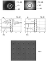
- the Figure 5 illustrates the evolution of the elementary diffraction figure associated with a cell, when said initially living cell is progressively deteriorated until it dies.
- the HeLa cell, initially alive, is subjected to a temperature rising from 37°C to 45°C in ten minutes.
- An elementary diffraction pattern of the cell was recorded every 30 seconds.
- the elementary diffraction figures are arranged in the chronological order of their acquisitions, from left to right and from bottom to top.
- the Figure 5 confirms that it is possible to define an intensity threshold on a central surface of an elementary diffraction figure associated with a cell, to discriminate a living cell from a dead cell.
- the Figure 6 schematically illustrates a device 60 for implementing the method for discriminating a living cell from a dead cell.
- the reference numerals 61, 62, 63, 64, 65, 66 correspond respectively to the reference numerals 11, 12, 13, 14, 15 and 16 of the Figure 1 .
- the light source 61 is arranged to illuminate a sample of a liquid solution comprising cells.
- the photodetector 66 is a matrix photodetector arranged opposite the light source, and arranged to acquire an overall diffraction figure of the sample, the overall diffraction figure comprising several elementary diffraction figures each associated with a cell.
- the photodetector 66 is connected to calculation means 67 receiving as input the global diffraction figure as defined above.
- the calculation means determine the light intensity on a central surface of an elementary diffraction figure associated with a cell, and output a classification of said cell in one of the two categories live cell 68 1 or dead cell 68 2 .
- the central surface is defined previously.
- the calculation means include in particular electronic means and computer and/or software means. It is typically a digital or analog electronic circuit, preferably dedicated, associated with a microprocessor and/or a computer.
- This method for discriminating a living cell from a dead cell can advantageously be implemented to control in situ a cell treatment in a bioreactor.
- the method for discriminating a living cell from a dead cell uses elementary diffraction figures each associated with a cell. For each elementary diffraction figure to be usable, the figures must not be superimposed on each other. For a given thickness, the sample 14 must therefore present a cell concentration lower than a predetermined maximum concentration.
- an immersible probe is proposed, intended in particular for the implementation of this method for discriminating a living cell from a dead cell. It will also be possible to envisage using this immersible probe for other uses. For this reason, it has been chosen below to describe the immersible probe alone, independently of the calculation means for implementing the steps of the method for discriminating a living cell from a dead cell.
- the principle implemented in this immersible probe consists in adapting the thickness of the sample to its concentration of particles, here cells.
- the immersible probe is suitable for measurements made by immersing the probe in a liquid solution. This dispenses with a step of taking a sample and depositing it on a coverslip. The disturbances of the sample due to its observation are also limited, since the sample is not isolated from the rest of the liquid solution.
- the Picture 7 schematically illustrates a first embodiment of an immersible probe 70, making it possible to adapt the thickness of the sample to its particle concentration.
- References 71 and 76 of the Picture 7 correspond respectively to references 11 and 16 of the Figure 1 .
- the light source 71 and the photodetector 76 therefore together form an imaging device without a lens as described with reference to the Figure 1 .
- the immersible probe 70 comprises a first sealed housing 711, receiving the light source 71.
- the light source 71 is therefore protected inside a sealed housing, which makes it possible to fully immerse the source, without risking damage it.
- the first sealed housing 711 has a first window 712, transparent to the emission wavelength of the light source 71.
- the first window 712 is located between the light source 71 and the photodetector 76.
- the immersible probe 70 also comprises a second sealed housing 761, receiving the photodetector 76.
- the photodetector 76 is therefore protected inside a sealed housing, which allows it to be fully immersed without risking damaging it. It is not simply a question here of covering the photodetector with a protective lamella, but of wrapping it entirely inside a box.
- the second sealed housing 761 has a second window 762, transparent to the emission wavelength of the light source 71.
- the second window 762 is located between the first window 712 and the photodetector 76.
- the sample is formed by a portion of the liquid solution in which the immersible probe 70 is completely immersed, this portion of liquid solution occupying the space 704 between the first transparent window 712 and the second transparent window 762.
- the liquid solution comprises particles such as cells.
- the photodetector 76 is arranged to acquire a global diffraction figure comprising a plurality of elementary diffraction figures, each associated with a particle. It is desired to adapt the thickness of the sample to its concentration of cells, so that at least 80% of the elementary diffraction figures of a global diffraction figure are not superimposed with another elementary diffraction figure. For this, the distance between the first transparent window 712 and the second transparent window 762 is variable.
- this distance is variable over time.
- the first transparent window 712 is parallel to the second transparent window 762.
- the second transparent window 762 is movable along an axis 701 orthogonal to the common plane of the first and second windows.
- the second housing 761 is fixed relative to a rod 702 oriented along the axis 701.
- the rod 702 is notched. It forms a rack, driven in translation by a pinion (not shown).
- the pinion is rotated by means of a wheel 703.
- the rod 702, carrying with it the second housing 761, can therefore be translated along the axis 701 relative to the first housing 711.
- a person skilled in the art may provide different variants making it possible to move a transparent window relative to the other transparent window, along an axis orthogonal to the plane of these two windows, without departing from the scope of the present invention.
- the immersible probe can be connected to computing means (not shown) as described above with reference to the Figure 6 .
- the device 60 as shown in Figure 6 may comprise an immersible probe making it possible to adapt the thickness of the sample to its particle concentration, the light source of the immersible source forming the light source 61 and the photodetector of the immersible probe forming the photodetector 66.
- the Picture 8 schematically illustrates a second embodiment of an immersible probe 80 making it possible to adapt the thickness of the sample to its particle concentration.
- the submersible probe 80 will only be described for its differences relative to the submersible probe 70.
- the reference numerals 81, 811, 812, 86, 861, 862 and 804 correspond respectively to the reference numerals 71, 711, 712, 76, 761, 762 and 704 of the Picture 7 .
- the distance between the first transparent window 812 and the second transparent window 862 is spatially variable.
- the first transparent window 812 is inclined at an angle ⁇ relative to the second transparent window 862, these two windows being flat.
- the angle ⁇ is typically between 10° and 45°.
- the light source 81 is formed by several unitary light sources 81 1 , 81 2 distributed above the first transparent window 812. This characteristic is not fundamental, and provision may also be made to use a light source made of a single LED or laser diode, as described with reference to Figure 1 .
- a surface 805 of the photodetector 86 corresponds to a small distance between the first transparent window 812 and the second transparent window 862. This surface 805 is used to acquire an overall diffraction figure when the liquid solution has for example a high concentration, for example greater than at 10 6 cells/mL.
- the surface 805 is located opposite the unitary light source 81 1 .
- a surface 806 of the photodetector 86 corresponds to a large distance between the first transparent window 812 and the second transparent window 862. This surface 806 is used to acquire an overall diffraction figure when the liquid solution has a low concentration, for example between 10 4 and 10 5 cells/mL.
- the surface 806 is located opposite the unitary light source 81 2 .
- the Picture 9 schematically illustrates a bioreactor 90.
- the bioreactor 90 here designates a device intended to cultivate cells or tissues within the framework of a cell culture, or to implement a chemical process involving organisms or active biochemical substances derived from these organizations.
- the bioreactor 90 receives a liquid solution 91 comprising cells. This solution is located in a tank 95 of the bioreactor.
- Openings made in the tank of the bioreactor make it possible to insert probes to control the conditions inside the bioreactor 90.
- One of these openings is used to insert an immersible probe 92 making it possible to adapt the thickness of the sample to its particle concentration.
- the immersible probe 92 has the shape of an elongated cylinder, with a diameter less than 12 mm and a length greater than 50 mm.
- the immersible probe 92 has an upper part 93 receiving the first sealed housing as described above, and a lower part 94 receiving the second sealed housing as described above. The space between these two housings is occupied by the liquid solution 91.
- the acquisition time of a global diffraction figure is advantageously of the order of a millisecond, to avoid the effect of the movement of the cells.
Landscapes
- Health & Medical Sciences (AREA)
- Life Sciences & Earth Sciences (AREA)
- Engineering & Computer Science (AREA)
- Chemical & Material Sciences (AREA)
- Physics & Mathematics (AREA)
- General Physics & Mathematics (AREA)
- General Health & Medical Sciences (AREA)
- Biochemistry (AREA)
- Biomedical Technology (AREA)
- Pathology (AREA)
- Immunology (AREA)
- Analytical Chemistry (AREA)
- Bioinformatics & Cheminformatics (AREA)
- Zoology (AREA)
- Wood Science & Technology (AREA)
- Organic Chemistry (AREA)
- Biotechnology (AREA)
- Genetics & Genomics (AREA)
- General Engineering & Computer Science (AREA)
- Sustainable Development (AREA)
- Microbiology (AREA)
- Molecular Biology (AREA)
- Optics & Photonics (AREA)
- Cell Biology (AREA)
- Biophysics (AREA)
- Hematology (AREA)
- Urology & Nephrology (AREA)
- Food Science & Technology (AREA)
- Medicinal Chemistry (AREA)
- Theoretical Computer Science (AREA)
- Computing Systems (AREA)
- Dispersion Chemistry (AREA)
- Signal Processing (AREA)
- Clinical Laboratory Science (AREA)
- Investigating Or Analysing Materials By Optical Means (AREA)
- Computer Vision & Pattern Recognition (AREA)
- Measuring Or Testing Involving Enzymes Or Micro-Organisms (AREA)
- Apparatus Associated With Microorganisms And Enzymes (AREA)
Description
La présente invention concerne l'utilisation d'une sonde immergeable en fonction d'une concentration en particules.The present invention relates to the use of an immersible probe as a function of a particle concentration.
On connaît dans l'art antérieur différents procédés pour discriminer une cellule vivante d'une cellule morte, ou en d'autres termes une cellule viable d'une cellule non-viable.Various methods are known in the prior art for discriminating a living cell from a dead cell, or in other words a viable cell from a non-viable cell.
On connaît par exemple des procédés de microscopie à fluorescence. Ces procédés utilisent un microscope optique pour visualiser un échantillon, ainsi qu'un marqueur fluorescent qui se fixe préférentiellement sur une catégorie de cellules, parmi les deux catégories cellules vivantes et cellules mortes. Le marqueur fluorescent absorbe un rayonnement incident à une première longueur d'onde, et émet en réponse un rayonnement de fluorescence à une deuxième longueur d'onde. On nomme « cellules marquées » les cellules fixées au marqueur fluorescent. On voit qu'en éclairant un échantillon de cellules marquées avec un rayonnement à la première longueur d'onde, on peut discriminer une cellule vivante d'une cellule morte en identifiant les cellules émettant le rayonnement de fluorescence à la deuxième longueur d'onde. En pratique, on va observer au microscope des cellules présentant une couleur correspondant à la longueur d'onde du rayonnement de fluorescence, et des cellules ne présentant pas cette couleur.For example, fluorescence microscopy methods are known. These methods use an optical microscope to visualize a sample, as well as a fluorescent marker which binds preferentially to a category of cells, among the two categories living cells and dead cells. The fluorescent label absorbs incident radiation at a first wavelength, and in response emits fluorescence radiation at a second wavelength. The cells fixed to the fluorescent marker are called “marked cells”. It can be seen that by illuminating a sample of cells marked with radiation at the first wavelength, it is possible to discriminate a living cell from a dead cell by identifying the cells emitting the fluorescence radiation at the second wavelength. In practice, cells exhibiting a color corresponding to the wavelength of the fluorescence radiation, and cells not exhibiting this color, will be observed under the microscope.
Pour marquer les cellules vivantes, on peut par exemple utiliser la calcéine AM en tant que marqueur fluorescent se fixant uniquement aux cellules vivantes. On connaît également l'iodure de proprium se fixant uniquement aux cellules mortes.To label living cells, it is possible, for example, to use calcein AM as a fluorescent marker binding only to living cells. Proprium iodide is also known to bind only to dead cells.
Un inconvénient de ces procédés est qu'ils sont invasifs : l'échantillon de cellules est perturbé par l'ajout du marqueur fluorescent.A disadvantage of these methods is that they are invasive: the cell sample is disturbed by the addition of the fluorescent label.
Un autre inconvénient de ces procédés est qu'ils sont onéreux : le microscope à fluorescence doit présenter d'excellentes performances optiques basées sur l'utilisation de composants optiques de grande qualité. De plus, leur champ est limité, souvent inférieur à 1 mm2, ce qui ne permet pas l'observation simultanée d'un grand nombre de cellules.Another disadvantage of these methods is that they are expensive: the fluorescence microscope must have excellent optical performance based on the use of high quality optical components. Moreover, their field is limited, often less than 1 mm 2 , which does not allow the simultaneous observation of a large number of cells.
Les inventeurs proposent dans la suite une méthode pour discriminer une cellule vivante d'une cellule morte, qui ne présente pas au moins l'un des inconvénients de l'art antérieur.The inventors propose below a method for discriminating a living cell from a dead cell, which does not have at least one of the drawbacks of the prior art.
La présente invention concerne un procédé d'utilisation d'une sonde immergeable, présentant un intérêt notamment dans le cadre de cette méthode pour discriminer une cellule vivante d'une cellule morte.The present invention relates to a method of using an immersible probe, of particular interest in the context of this method for discriminating a living cell from a dead cell.
A cet égard, on connaît l'article de
On connaît également le document
La présente invention est définie par un procédé d'utilisation d'une sonde immergeable, la sonde immergeable comprenant :
- une source lumineuse, agencée pour illuminer un échantillon d'une solution liquide comprenant des particules ;
- un photodétecteur matriciel disposé en face de la source lumineuse, agencé pour acquérir une figure de diffraction globale de l'échantillon, la figure de diffraction globale comprenant plusieurs figures de diffraction élémentaires associées chacune à une particule ;
- un premier logement étanche, recevant la source lumineuse et présentant une première fenêtre transparente entre la source lumineuse et le photodétecteur matriciel ;
- un second logement étanche, recevant le photodétecteur matriciel, et présentant une seconde fenêtre transparente entre la première fenêtre transparente et le photodétecteur matriciel, la distance entre la première fenêtre transparente et la seconde fenêtre transparente étant variable dans l'espace ou variable dans le temps.
- a light source, arranged to illuminate a sample of a liquid solution comprising particles;
- a matrix photodetector arranged opposite the light source, arranged to acquire an overall diffraction figure of the sample, the overall diffraction figure comprising several elementary diffraction figures each associated with a particle;
- a first sealed housing, receiving the light source and having a first transparent window between the light source and the matrix photodetector;
- a second sealed housing, receiving the matrix photodetector, and having a second transparent window between the first transparent window and the matrix photodetector, the distance between the first transparent window and the second transparent window being variable in space or variable in time.
Selon ce procédé :
- on immerge la sonde immergeable dans une solution liquide comprenant des particules telles que des cellules, ladite solution liquide occupant l'espace entre la première fenêtre transparente et la seconde fenêtre transparente ;
- on définit une distance entre la première fenêtre transparente et la seconde fenêtre transparente, en fonction de la concentration en particules de la solution liquide et de sorte qu'au moins 30%, voire 50% ou 80% des figures de diffraction élémentaires d'une figure de diffraction globale ne soient pas superposées avec une autre figure de diffraction élémentaire, chaque figure de diffraction élémentaire étant associée à une particule telle qu'une cellule ; et
- the immersible probe is immersed in a liquid solution comprising particles such as cells, said liquid solution occupying the space between the first transparent window and the second transparent window;
- a distance is defined between the first transparent window and the second transparent window, depending on the particle concentration of the liquid solution and so that at least 30%, even 50% or 80% of the elementary diffraction figures of a global diffraction figure are not superimposed with another elementary diffraction figure, each elementary diffraction figure being associated with a particle such as a cell; and
D'autres caractéristiques préférées de l'invention sont définies dans les revendications 2 à 10.Other preferred features of the invention are defined in
La présente invention sera mieux comprise à la lecture de la description d'exemples de réalisation donnés à titre purement indicatif et nullement limitatif, en faisant référence aux dessins annexés parmi lesquels :
- la
Figure 1 illustre un dispositif connu d'imagerie sans lentille ; - les
Figures 2A et 2B illustrent une figure de diffraction obtenue à l'aide du dispositif de laFigure 1 et pour une cellule vivante ; - les
Figures 3A et 3B illustrent une figure de diffraction obtenue à l'aide du dispositif de laFigure 1 et pour une cellule morte ; - la
Figure 4A illustre un disque central de la figure de diffraction représentée enFigure 2A ; - la
Figure 4B illustre un disque central de la figure de diffraction représentée enFigure 3A ; - les
Figures 4C et 4D illustrent un indicateur numérique d'une méthode pour discriminer une cellule vivante d'une cellule morte ; - la
Figure 5 illustre l'évolution de la figure de diffraction associée à une cellule, lorsque ladite cellule initialement vivante est progressivement rendue non viable jusqu'à ce qu'elle meurt ; - la
Figure 6 illustre de façon schématique un dispositif pour mettre en œuvre la méthode pour discriminer une cellule vivante d'une cellule morte ; - la
Figure 7 illustre de façon schématique un premier mode de réalisation de sonde immergeable utilisée dans le procédé selon l'invention ; - la
Figure 8 illustre de façon schématique un deuxième mode de réalisation de sonde immergeable utilisée dans le procédé selon l'invention ; et - la
Figure 9 illustre de façon schématique un bioréacteur dans lequel on peut immerger une sonde.
- the
Figure 1 illustrates a known lensless imaging device; - the
Figures 2A and 2B illustrate a diffraction figure obtained using the device of theFigure 1 and for a living cell; - the
Figures 3A and 3B illustrate a diffraction figure obtained using the device of theFigure 1 and for a dead cell; - the
Figure 4A illustrates a central disk of the diffraction pattern shown inFigure 2A ; - the
Figure 4B illustrates a central disk of the diffraction pattern shown inFigure 3A ; - the
Figures 4C and 4D illustrate a numerical indicator of a method for discriminating a living cell from a dead cell; - the
Figure 5 illustrates the evolution of the diffraction pattern associated with a cell, when said initially living cell is gradually rendered non-viable until it dies; - the
Figure 6 schematically illustrates a device for implementing the method for discriminating a living cell from a dead cell; - the
Picture 7 schematically illustrates a first embodiment of an immersible probe used in the method according to the invention; - the
Figure 8 schematically illustrates a second embodiment of an immersible probe used in the method according to the invention; and - the
Figure 9 schematically illustrates a bioreactor in which a probe can be immersed.
On décrit pour commencer une méthode pour discriminer une cellule vivante d'une cellule morte.We begin by describing a method for discriminating a living cell from a dead cell.
On va tout d'abord décrire, en référence à la
Une source lumineuse 11 émet un faisceau lumineux 12 illuminant un échantillon 14. La source lumineuse est, de préférence, cohérente spatialement. La source lumineuse peut être une diode laser, ou une diode électroluminescente (LED) suivie d'un trou de filtrage. Le trou de filtrage permet d'améliorer la cohérence spatiale du faisceau lumineux émis par la LED. Avantageusement, la source lumineuse est également temporellement cohérente.A
On utilise par exemple une LED dont le spectre d'émission est centré sur 450 nm, soit une émission dans le bleu. La largeur du pic à 450 nm est de 40 nm. La puissance d'émission de la LED est par exemple comprise entre 100 mW et 1 W. La LED est suivie par un trou de filtrage de diamètre 150 µm, placé directement au contact de la LED.For example, an LED is used whose emission spectrum is centered on 450 nm, ie an emission in the blue. The peak width at 450 nm is 40 nm. The emission power of the LED is for example between 100 mW and 1 W. The LED is followed by a filtering hole with a diameter of 150 μm, placed directly in contact with the LED.
L'échantillon 14 est placé entre la source lumineuse 11 et un photodétecteur matriciel 16.
Dans l'exemple représenté sur la
L'échantillon 14 est par exemple un échantillon d'un liquide biologique tel que le sang, une solution de culture de cellules, un échantillon prélevé dans la nature tel qu'un échantillon de l'eau d'un lac, etc. Le dispositif 10 permet de détecter des particules contenues dans l'échantillon et présentant un faible diamètre, typiquement entre 100 nm et 500 µm.The
Le photodétecteur matriciel 16 convertit un rayonnement électromagnétique incident en un signal électrique analogique. Ce photodétecteur matriciel 16 est généralement relié à un convertisseur analogique-numérique de façon à fournir une image numérique. On parle de photodétecteur matriciel, car la surface de détection du photodétecteur est découpée en pixels formant une matrice. Le photodétecteur matriciel 16 est par exemple un capteur CCD (pour l'anglais « Charge-Coupled Device ») ou un capteur CMOS (pour l'anglais «Complementary Metal Oxide Semiconductor »). Chaque pixel du photodétecteur est par exemple un carré de côté inférieur à 9 µm, et même inférieur à 5 µm, par exemple 2,2 µm. En particulier, on peut utiliser un capteur CMOS de 24 mm2, présentant un pas de pixel de 2,2 µm.The
Le photodétecteur matriciel 16 détecte une figure de diffraction correspondant à l'influence des particules de l'échantillon 14 sur le faisceau lumineux 12. En particulier, le photodétecteur matriciel 16 détecte une figure de diffraction, correspondant aux interférences entre une onde lumineuse incidente provenant directement de la source lumineuse 11 et une onde lumineuse diffractée par des particules de l'échantillon 14. On nomme « hologramme » une telle figure de diffraction. Un avantage d'une telle figure de diffraction est que le signal détecté est de grande amplitude, grâce à la contribution du signal provenant directement de la source lumineuse. Un autre avantage de cette figure de diffraction est que le champ de vision détecté est large, par exemple supérieur à 20 mm2. Le photodétecteur 16 est positionné à proximité de l'échantillon 14, par exemple à 0,8 mm de la lamelle 15 (lamelle du côté du photodétecteur 16).The
On détecte donc une figure de diffraction correspondant à un objet, et non directement l'image de cet objet. On nomme cette technique « imagerie sans lentille ». Dans tout le texte, on nomme « dispositif d'imagerie sans lentille » un dispositif de ce type, pour détecter une figure de diffraction correspondant à un objet. Il faut noter qu'un tel dispositif peut comprendre une matrice de microlentilles, servant à focaliser sur chaque pixel le faisceau correspondant aux interférences à détecter. Cependant, un tel dispositif ne comporte pas d'optique de grossissement disposée entre l'objet et le photodétecteur.A diffraction figure corresponding to an object is therefore detected, and not directly the image of this object. This technique is called “lensless imaging”. Throughout the text, the term “lensless imaging device” refers to a device of this type, for detecting a diffraction figure corresponding to an object. It should be noted that such a device can comprise a matrix of microlenses, serving to focus on each pixel the beam corresponding to the interferences to be detected. However, such a device does not include magnification optics placed between the object and the photodetector.
L'homme du métier saura aisément positionner les uns par rapport aux autres chacun des éléments parmi la source lumineuse 11, l'échantillon 14 et le photodétecteur 16.A person skilled in the art will easily know how to position relative to each other each of the elements among the
Selon une méthode pour discriminer une cellule vivante d'une cellule morte, on utilise ce dispositif 10 avec un échantillon 14 d'une solution liquide comprenant des cellules. Par exemple, on utilise une solution de cellules cancéreuses HeLa. On choisit en particulier d'utiliser un échantillon volumique : l'épaisseur entre les deux lamelles 13, 15 est par exemple de 0,2 mm. Le volume d'échantillon 14, imagé sur le photodétecteur 16 sous la forme d'une figure de diffraction, est d'environ 5 µL.According to a method for discriminating a living cell from a dead cell, this
On acquiert ainsi, sur le photodétecteur 16, une figure de diffraction globale correspondant aux interférences entre des ondes provenant directement de la source lumineuse 11 et des ondes émises par la source lumineuse puis diffractées par les cellules de l'échantillon 14. La figure de diffraction globale comprend plusieurs figures de diffraction élémentaires. Chaque figure de diffraction élémentaire est associée à une cellule de l'échantillon 14, et correspond aux interférences entre des ondes provenant directement de la source lumineuse 11 et des ondes émises par la source lumineuse puis diffractées par ladite cellule.There is thus acquired, on the
On a remarqué qu'une figure de diffraction élémentaire présente un profil caractéristique selon que la cellule est vivante ou morte.It has been noticed that an elementary diffraction figure has a characteristic profile depending on whether the cell is alive or dead.
La
La
La
La
Les
On observe sur la
La différence entre la figure de diffraction élémentaire 20 associée à une cellule vivante et la figure de diffraction élémentaire 30 associée à une cellule morte est suffisamment significative pour permettre une détection de l'état de la cellule à partir de sa figure de diffraction. On va donc pouvoir exploiter cette différence pour discriminer une cellule vivante d'une cellule morte.The difference between the elementary diffraction figure 20 associated with a living cell and the elementary diffraction figure 30 associated with a dead cell is significant enough to allow detection of the state of the cell from its diffraction figure. We will therefore be able to use this difference to discriminate between a living cell and a dead cell.
On remarque que les deux figures de diffraction élémentaires diffèrent en particulier sur une zone centrale, ici en forme de disque, définie sur une figure de diffraction. Ce disque est centré sur le centre des anneaux de ladite figure de diffraction élémentaire. Il est délimité par le premier anneau d'une figure de diffraction élémentaire. Ce premier anneau correspond ici à l'anneau d'intensité lumineuse minimale. On reconnaît sur la
On peut relever qu'une modification du profil d'une cellule, par exemple pour prendre une forme ovale, se traduira par une modification de la figure de diffraction élémentaire associée. La figure de diffraction élémentaire associée présentera toujours une succession de courbes fermées concentriques, que par abus de langage on nommera également « anneaux de diffraction ». Ces courbes fermées entoureront une surface délimitée par un plus petit anneau de diffraction élémentaire.It can be noted that a modification of the profile of a cell, for example to take an oval shape, will result in a modification of the associated elementary diffraction figure. The associated elementary diffraction figure will always present a succession of concentric closed curves, which by abuse of language will be called also "diffraction rings". These closed curves will surround a surface bounded by a smaller elementary diffraction ring.
L'idée à la base de la méthode pour discriminer une cellule vivante d'une cellule morte consiste à utiliser une intensité lumineuse sur une surface centrale d'une figure de diffraction élémentaire, pour classer une cellule correspondante dans la catégorie cellule vivante ou dans la catégorie cellule morte. Cette surface est dite centrale, car elle est concentrique avec les anneaux de diffraction. La surface centrale est notamment inscrite dans une surface délimitée par un plus petit anneau de diffraction. Une telle surface correspond par exemple au disque central tel que défini ci-avant.The idea underlying the method for discriminating a living cell from a dead cell consists in using a light intensity on a central surface of an elementary diffraction figure, to classify a corresponding cell in the living cell category or in the dead cell category. This surface is called central because it is concentric with the diffraction rings. The central surface is in particular inscribed in a surface delimited by a smaller diffraction ring. Such a surface corresponds for example to the central disc as defined above.
On voit donc que l'on offre un procédé pour discriminer une cellule vivante d'une cellule morte, qui ne nécessite pas l'ajout d'une substance de marquage.It can therefore be seen that a method is provided for discriminating a living cell from a dead cell, which does not require the addition of a labeling substance.
Les moyens matériels pour mettre en œuvre ce procédé sont simples et peu onéreux : il s'agit en particulier d'un dispositif d'imagerie sans lentille. Le dispositif d'imagerie ne nécessite pas l'utilisation d'optiques coûteuses. La méthode pour discriminer une cellule vivante d'une cellule morte ne nécessite pas l'utilisation de moyens de calcul très puissants, car on ne cherche pas à reconstruire une image des cellules à partir de leurs figures de diffraction élémentaires. On ne cherche pas non plus à traiter des figures de diffraction élémentaires pour les comparer à une bibliothèque de figures de diffraction de référence. On classe une cellule simplement en utilisant une intensité lumineuse sur une surface prédéterminée.The material means for implementing this method are simple and inexpensive: it is in particular a lensless imaging device. The imaging device does not require the use of expensive optics. The method for discriminating a living cell from a dead cell does not require the use of very powerful calculation means, since no attempt is made to reconstruct an image of the cells from their elementary diffraction figures. Nor is it sought to process elementary diffraction figures in order to compare them with a library of reference diffraction figures. A cell is classified simply by using a light intensity on a predetermined surface.
En outre, puisque l'on ne cherche pas ici à reconstruire l'image d'une cellule, il n'est pas nécessaire de connaître la distance entre la cellule et le photodétecteur. On peut donc facilement analyser une population de cellules contenues dans un volume, et pas seulement dans un plan.Furthermore, since the aim here is not to reconstruct the image of a cell, it is not necessary to know the distance between the cell and the photodetector. It is therefore easy to analyze a population of cells contained in a volume, and not only in a plane.
Il n'est pas non plus nécessaire de prévoir une focalisation sur un plan particulier, ce qui permet là-encore d'analyser facilement une population de cellules contenues dans un volume.Nor is it necessary to provide focusing on a particular plane, which again makes it possible to easily analyze a population of cells contained in a volume.
Un autre avantage de cette méthode pour discriminer une cellule vivante d'une cellule morte est sa précision : on peut réaliser un comptage précis d'un nombre de cellules vivantes et d'un nombre de cellules mortes, dans une région donnée.Another advantage of this method for discriminating a living cell from a dead cell is its precision: it is possible to carry out a precise count of a number of living cells and of a number of dead cells, in a given region.
On va maintenant illustrer plus précisément l'utilisation d'une intensité lumineuse sur une surface centrale d'une figure de diffraction élémentaire.We will now illustrate more precisely the use of a light intensity on a central surface of an elementary diffraction figure.
La
La
On voit donc qu'il suffit d'évaluer l'intensité lumineuse sur une surface centrale inscrite dans le disque central 41 ou 42, pour savoir si une cellule correspondante est vivante ou morte.It can therefore be seen that it suffices to evaluate the light intensity on a central surface inscribed in the
On pourra définir un indicateur numérique, servant à caractériser l'intensité lumineuse dans la surface centrale 45 ou 46. Dans l'exemple représenté sur les
La
On utilise la valeur de cet indicateur numérique pour classer une cellule dans la catégorie cellule vivante ou cellule morte.The value of this numerical indicator is used to classify a cell into the living cell or dead cell category.
On fixe une valeur de seuil prédéterminée, séparant des valeurs d'indicateur numérique associées à une cellule vivante et des valeurs d'indicateur numérique associées à une cellule morte.A predetermined threshold value is fixed, separating digital indicator values associated with a living cell and digital indicator values associated with a dead cell.
Ainsi, il suffit, pour distinguer une cellule vivante d'une cellule morte, de :
- calculer ledit indicateur numérique ; puis
- comparer l'indicateur numérique à une valeur seuil prédéterminée.
- calculating said digital indicator; then
- comparing the digital indicator to a predetermined threshold value.
On pourra prévoir différentes types d'indicateurs numériques. Par exemple, on pourra considérer un maximum absolu d'intensité lumineuse, une amplitude crête à crête de l'intensité lumineuse, etc.It is possible to provide different types of digital indicators. For example, we can consider an absolute maximum of light intensity, a peak-to-peak amplitude of the light intensity, etc.
On a pris ici l'exemple des cellules HeLa, mais on pourra ainsi classer tout type de cellule.Here we have taken the example of HeLa cells, but we can thus classify any type of cell.
Le profil caractéristique de la figure de diffraction élémentaire associée à une cellule vivante ou une cellule morte peut dépendre du type de cellule étudié. Ainsi, il pourra arriver qu'une faible intensité lumineuse au centre de la figure de diffraction élémentaire corresponde à une cellule morte et qu'une forte intensité lumineuse au centre de la figure de diffraction élémentaire corresponde à une cellule vivante.The characteristic profile of the elementary diffraction figure associated with a living cell or a dead cell may depend on the type of cell studied. Thus, it may happen that a low light intensity at the center of the elementary diffraction figure corresponds to a dead cell and that a high light intensity at the center of the elementary diffraction figure corresponds to a living cell.
La
La
La source lumineuse 61 est agencée pour illuminer un échantillon d'une solution liquide comprenant des cellules.The
Le photodétecteur 66 est un photodétecteur matriciel disposé en face de la source lumineuse, et agencé pour acquérir une figure de diffraction globale de l'échantillon, la figure de diffraction globale comprenant plusieurs figures de diffraction élémentaires associées chacune à une cellule.The
Le photodétecteur 66 est relié à des moyens de calcul 67 recevant en entrée la figure de diffraction globale telle que définie ci-avant.The
Les moyens de calcul déterminent l'intensité lumineuse sur une surface centrale d'une figure de diffraction élémentaire associée à une cellule, et fournissent en sortie un classement de ladite cellule dans l'une parmi les deux catégories cellule vivante 681 ou cellule morte 682. La surface centrale est définie précédemment.The calculation means determine the light intensity on a central surface of an elementary diffraction figure associated with a cell, and output a classification of said cell in one of the two categories live cell 68 1 or dead cell 68 2 . The central surface is defined previously.
En particulier, les moyens de calcul sont agencés pour :
- calculer l'indicateur numérique tel que défini précédemment ;
- comparer cet indicateur numérique à une valeur de seuil prédéterminée ;
- attribuer la cellule correspondant à ladite figure de diffraction élémentaire, à l'une parmi les deux catégories 681 et 682.
- calculating the digital indicator as defined previously;
- comparing this digital indicator to a predetermined threshold value;
- assigning the cell corresponding to said elementary diffraction figure to one of the two categories 68 1 and 68 2 .
Les moyens de calcul comprennent notamment des moyens électroniques et des moyens informatiques et/ou logiciels. Il s'agit typiquement d'un circuit électronique numérique ou analogique, de préférence dédié, associé à un microprocesseur et/ou un ordinateur.The calculation means include in particular electronic means and computer and/or software means. It is typically a digital or analog electronic circuit, preferably dedicated, associated with a microprocessor and/or a computer.
Cette méthode pour discriminer une cellule vivante d'une cellule morte peut avantageusement être mise en œuvre pour contrôler in situ un traitement cellulaire dans un bioréacteur.This method for discriminating a living cell from a dead cell can advantageously be implemented to control in situ a cell treatment in a bioreactor.
La méthode pour discriminer une cellule vivante d'une cellule morte utilise des figures de diffraction élémentaires associées chacune à une cellule. Pour que chaque figure de diffraction élémentaire soit exploitable, il faut que les figures ne soient pas superposées les unes aux autres. Pour une épaisseur donnée, l'échantillon 14 doit donc présenter une concentration en cellules inférieure à une concentration maximale prédéterminée.The method for discriminating a living cell from a dead cell uses elementary diffraction figures each associated with a cell. For each elementary diffraction figure to be usable, the figures must not be superimposed on each other. For a given thickness, the
Par exemple, dans le mode de réalisation décrit en référence à la
On voit donc qu'il peut être nécessaire de pouvoir adapter à la concentration en cellules de l'échantillon 14, un dispositif d'imagerie sans lentille utilisé pour mettre en œuvre la méthode pour discriminer une cellule vivante d'une cellule morte.It can therefore be seen that it may be necessary to be able to adapt to the cell concentration of
On propose à cette fin une sonde immergeable, destinée notamment à la mise en œuvre de cette méthode pour discriminer une cellule vivante d'une cellule morte. On pourra également envisager d'utiliser cette sonde immergeable pour d'autres utilisations. Pour cette raison, on a choisi dans la suite de décrire la sonde immergeable seule, indépendamment de moyens de calcul pour mettre en œuvre des étapes de la méthode pour discriminer une cellule vivante d'une cellule morte.To this end, an immersible probe is proposed, intended in particular for the implementation of this method for discriminating a living cell from a dead cell. It will also be possible to envisage using this immersible probe for other uses. For this reason, it has been chosen below to describe the immersible probe alone, independently of the calculation means for implementing the steps of the method for discriminating a living cell from a dead cell.
Le principe mis en œuvre dans cette sonde immergeable consiste à adapter l'épaisseur de l'échantillon à sa concentration en particules, ici des cellules.The principle implemented in this immersible probe consists in adapting the thickness of the sample to its concentration of particles, here cells.
La sonde immergeable est adaptée à des mesures réalisées en plongeant la sonde dans une solution liquide. On s'affranchit ainsi d'une étape de prélèvement d'échantillon et dépôt sur une lamelle. On limite également les perturbations de l'échantillon dues à son observation, puisque l'échantillon n'est pas isolé du reste de la solution liquide.The immersible probe is suitable for measurements made by immersing the probe in a liquid solution. This dispenses with a step of taking a sample and depositing it on a coverslip. The disturbances of the sample due to its observation are also limited, since the sample is not isolated from the rest of the liquid solution.
La
Les références 71 et 76 de la
La sonde immergeable 70 comprend un premier logement étanche 711, recevant la source lumineuse 71. La source lumineuse 71 est donc protégée à l'intérieur d'un logement étanche, ce qui permet d'immerger entièrement la source, sans risquer de l'endommager. Le premier logement étanche 711 présente une première fenêtre 712, transparente à la longueur d'onde d'émission de la source lumineuse 71. La première fenêtre 712 est située entre la source lumineuse 71 et le photodétecteur 76.The
La sonde immergeable 70 comprend également un second logement étanche 761, recevant le photodétecteur 76. Le photodétecteur 76 est donc protégé à l'intérieur d'un logement étanche, ce qui permet de l'immerger entièrement sans risquer de l'endommager. Il ne s'agit pas simplement ici de recouvrir le photodétecteur d'une lamelle de protection, mais de l'envelopper entièrement à l'intérieur d'un boîtier. Le second logement étanche 761 présente une seconde fenêtre 762, transparente à la longueur d'onde d'émission de la source lumineuse 71. La seconde fenêtre 762 est située entre la première fenêtre 712 et le photodétecteur 76.The
L'échantillon est formé par une portion de la solution liquide dans laquelle la sonde immergeable 70 est entièrement plongée, cette portion de solution liquide occupant l'espace 704 entre la première fenêtre transparente 712 et la seconde fenêtre transparente 762. La solution liquide comprend des particules telles que des cellules.The sample is formed by a portion of the liquid solution in which the
Le photodétecteur 76 est agencé pour acquérir une figure de diffraction globale comprenant une pluralité de figures de diffraction élémentaires, chacune associée à une particule. On souhaite adapter l'épaisseur de l'échantillon à sa concentration en cellules, de sorte qu'au moins 80% des figures de diffraction élémentaires d'une figure de diffraction globale ne soient pas superposées avec une autre figure de diffraction élémentaire. Pour cela, la distance entre la première fenêtre transparente 712 et la seconde fenêtre transparente 762 est variable.The
Dans le mode de réalisation représenté sur la
La première fenêtre transparente 712 est parallèle à la seconde fenêtre transparente 762. La seconde fenêtre transparente 762 est mobile selon un axe 701 orthogonal au plan commun des première et seconde fenêtres.The first
Le second logement 761 est fixe relativement à une tige 702 orientée selon l'axe 701. La tige 702 est crantée. Elle forme une crémaillère, entraînée en translation par un pignon (non représenté). Le pignon est mis en rotation par l'intermédiaire d'une molette 703. La tige 702, entraînant avec elle le second logement 761, peut donc être translatée selon l'axe 701 relativement au premier logement 711.The
L'homme du métier pourra prévoir différentes variantes permettant de réaliser un déplacement d'une fenêtre transparente relativement à l'autre fenêtre transparente, selon un axe orthogonal au plan de ces deux fenêtres, sans sortir du cadre de la présente invention.A person skilled in the art may provide different variants making it possible to move a transparent window relative to the other transparent window, along an axis orthogonal to the plane of these two windows, without departing from the scope of the present invention.
On peut ainsi ajuster la distance entre la première fenêtre transparente 712 et la seconde fenêtre transparente 762, en déplaçant la seconde fenêtre transparente 762 relativement à la première fenêtre transparente 712.It is thus possible to adjust the distance between the first
La sonde immergeable peut être reliée à des moyens de calcul (non représentés) tels que décrits ci-avant en référence à la
La
La sonde immergeable 80 ne sera décrite que pour ses différences relativement à la sonde immergeable 70. Sur la
Dans le mode de réalisation représenté sur la
La première fenêtre transparente 812 est inclinée d'un angle α relativement à la seconde fenêtre transparente 862, ces deux fenêtres étant planes. L'angle α est typiquement compris entre 10° et 45°.The first
En variante, on pourrait prévoir une fenêtre plane, et une fenêtre présentant un profil en marches d'escalier.As a variant, one could provide a plane window, and a window having a stepped profile.
La source lumineuse 81 est formée par plusieurs sources lumineuses unitaires 811, 812 réparties au-dessus de la première fenêtre transparente 812. Cette caractéristique n'est pas fondamentale, et on pourra également prévoir d'utiliser une source lumineuse faite d'une unique LED ou diode laser, comme décrit en référence à la
Une surface 805 du photodétecteur 86 correspond à une faible distance entre la première fenêtre transparente 812 et la seconde fenêtre transparente 862. On utilise cette surface 805 pour acquérir une figure de diffraction globale lorsque la solution liquide présente par exemple une forte concentration, par exemple supérieure à 106 cellules/mL. La surface 805 est située en face de la source lumineuse unitaire 811.A
Une surface 806 du photodétecteur 86 correspond à une grande distance entre la première fenêtre transparente 812 et la seconde fenêtre transparente 862. On utilise cette surface 806 pour acquérir une figure de diffraction globale lorsque la solution liquide présente une faible concentration, par exemple comprise entre 104 et 105 cellules/mL. La surface 806 est située en face de la source lumineuse unitaire 812.A
On peut ainsi ajuster la distance entre la première fenêtre transparente 812 et la seconde fenêtre transparente 862, en définissant une portion du photodétecteur 86 utilisée pour obtenir des figures de diffraction élémentaires à analyser.It is thus possible to adjust the distance between the first
La
Un bioréacteur est conçu pour offrir des conditions optimales à une culture cellulaire ou un processus chimique. Pour cela, on ajuste et contrôle différents paramètres tels que :
- l'agitation de la solution liquide contenant les cellules, organismes ou substances biochimiques actives ;
- le pH de cette solution ;
- la température de cette solution ;
- le taux d'oxygène dissout dans cette solution.
- agitating the liquid solution containing the active cells, organisms or biochemicals;
- the pH of this solution;
- the temperature of this solution;
- the level of dissolved oxygen in this solution.
Dans l'exemple représenté sur la
Des ouvertures pratiquées dans la cuve du bioréacteur permettent d'insérer des sondes pour contrôler les conditions à l'intérieur du bioréacteur 90. L'une de ces ouvertures est utilisée pour insérer une sonde immergeable 92 permettant d'adapter l'épaisseur de l'échantillon à sa concentration en particules. La sonde immergeable 92 présente une forme de cylindre allongé, de diamètre inférieur à 12 mm et de longueur supérieure à 50 mm. La sonde immergeable 92 présente une partie supérieure 93 recevant le premier logement étanche tel que décrit ci-avant, et une partie inférieure 94 recevant le second logement étanche tel que décrit ci-avant. L'espace entre ces deux logements est occupé par la solution liquide 91.Openings made in the tank of the bioreactor make it possible to insert probes to control the conditions inside the
On peut ainsi mesurer l'évolution au cours du temps d'un taux de cellules vivantes dans le bioréacteur. Le temps d'acquisition d'une figure de diffraction globale est avantageusement de l'ordre de la milliseconde, pour éviter l'effet du mouvement des cellules.It is thus possible to measure the evolution over time of a rate of living cells in the bioreactor. The acquisition time of a global diffraction figure is advantageously of the order of a millisecond, to avoid the effect of the movement of the cells.
Claims (10)
- Method of using an immersible probe (70; 80; 92), the immersible probe comprising:- a light source (71; 81), arranged to illuminate a sample of a liquid solution containing particles;- a matrix photodetector (76; 86) disposed facing the light source, arranged to acquire a global diffraction figure of the sample, the global diffraction figure comprising a plurality of elementary diffraction figures (20; 30) each associated with a particle;- a first tight housing (711; 811), holding the light source and having a first transparent window (712; 812) between the light source and the matrix photodetector;- a second tight housing (761; 861), holding the matrix photodetector, and having a second transparent window (762; 862) between the first transparent window and the matrix photodetector, the distance between the first transparent window and the second transparent window being variable in space or variable in time;in which the method comprises the following steps:- the immersible probe (70; 80; 92) is immersed in a liquid solution comprising particles such as cells, said liquid solution occupying the space between the first transparent window (712; 812) and the second transparent window (762; 862);- a distance between the first transparent window (712; 812) and the second transparent window (762; 862) is defined as a function of the particle concentration in the liquid solution and such that at least 30% of the elementary diffraction figures (20; 30) in a global diffraction figure are not superimposed with another elementary diffraction figure, each elementary diffraction figure being associated with a particle such as a cell; andwith the use of the matrix photodetector (76; 86), and for said distance thus defined, a global diffraction figure of the sample is acquired, wherein the sample is formed by a portion of said liquid solution disposed between the first transparent window (712; 812) and the second transparent window (762; 862).
- Method according to claim 1, wherein the distance between the first transparent window (712; 812) and the second transparent window (762; 862) is defined such that at least 50% of the elementary diffraction figures (20; 30) of a global diffraction figure are not superimposed with another elementary diffraction figure.
- Method according to claim 1, wherein the distance between the first transparent window (712; 812) and the second transparent window (762; 862) is defined such that at least 80% of the elementary diffraction figures (20; 30) of a global diffraction figure are not superimposed with another elementary diffraction figure.
- Method according to any one of claims 1 to 3, wherein the distance between the first transparent window (712; 812) and the second transparent window (762; 862) depends on a particles concentration in the liquid solution.
- Method according to any one of claims 1 to 4, wherein:- the distance between the first transparent window (812) and the second transparent window (862) is variable in space, with the first transparent window and the second transparent window defining two planes inclined relative to each other, such that the distance between the first transparent window and the second transparent window depends on the location on the second transparent window (862);- the distance between the first transparent window (812) and the second transparent window (862) is defined by defining a portion (805; 806) of the matrix photodetector (86) used to obtain the global diffraction figure; and- said global diffraction figure is acquired using said portion (805; 806) of the matrix photodetector (86).
- Method according to any one of claims 1 to 4, wherein:- the distance between the first transparent window (712) and the second transparent window (762) is variable in time, with the first transparent window and the second transparent window defining two planes parallel to each other, and with the immersible probe which comprises means (702, 703) for moving the second transparent window relative to the first transparent window; and- the first transparent window is moved relative to the second transparent window; and- said global diffraction figure is acquired with the use of the matrix photodetector (76).
- Method according to claim 6, wherein the means (702, 703) for moving the second transparent window relative to the first transparent window include a rack driven in translation by a gear, and fixed relative to the second tight housing (761).
- Method according to any one of claims 1 to 7, wherein the light source (71; 81) is spatially coherent.
- Method according to any one of claims 1 to 8, wherein the immersible probe (92) is immersed in a liquid solution (91), said liquid solution (91) being located in a tank (95) of a bioreactor (90).
- Method according to any one of claims 1 to 9, wherein the method then comprises the following steps:- a global diffraction figure is acquired using the matrix photodetector (76; 86), the global diffraction figure comprising a plurality of elementary diffraction figures (20; 30) each associated with a cell, each elementary diffraction figure having a sequence of concentric closed curves; and- a cell is classified as being in the living cells (681) or dead cell (682) category, depending on a light intensity on a central area (45; 46) of an elementary diffraction figure (20; 30) associated with said cell.
Applications Claiming Priority (3)
| Application Number | Priority Date | Filing Date | Title |
|---|---|---|---|
| FR1357240A FR3009084B1 (en) | 2013-07-23 | 2013-07-23 | METHOD FOR SORTING CELLS AND ASSOCIATED DEVICE |
| EP14747543.8A EP3025144B1 (en) | 2013-07-23 | 2014-07-21 | Cell-sorting method and associated device |
| PCT/EP2014/065636 WO2015011096A1 (en) | 2013-07-23 | 2014-07-21 | Cell-sorting method and associated device |
Related Parent Applications (2)
| Application Number | Title | Priority Date | Filing Date |
|---|---|---|---|
| EP14747543.8A Division EP3025144B1 (en) | 2013-07-23 | 2014-07-21 | Cell-sorting method and associated device |
| EP14747543.8A Division-Into EP3025144B1 (en) | 2013-07-23 | 2014-07-21 | Cell-sorting method and associated device |
Publications (2)
| Publication Number | Publication Date |
|---|---|
| EP3208599A1 EP3208599A1 (en) | 2017-08-23 |
| EP3208599B1 true EP3208599B1 (en) | 2022-03-09 |
Family
ID=49378471
Family Applications (2)
| Application Number | Title | Priority Date | Filing Date |
|---|---|---|---|
| EP17165937.8A Active EP3208599B1 (en) | 2013-07-23 | 2014-07-21 | Method for using a submersible probe, as a function of a particle concentration |
| EP14747543.8A Active EP3025144B1 (en) | 2013-07-23 | 2014-07-21 | Cell-sorting method and associated device |
Family Applications After (1)
| Application Number | Title | Priority Date | Filing Date |
|---|---|---|---|
| EP14747543.8A Active EP3025144B1 (en) | 2013-07-23 | 2014-07-21 | Cell-sorting method and associated device |
Country Status (5)
| Country | Link |
|---|---|
| US (1) | US10400208B2 (en) |
| EP (2) | EP3208599B1 (en) |
| JP (1) | JP6487434B2 (en) |
| FR (1) | FR3009084B1 (en) |
| WO (1) | WO2015011096A1 (en) |
Families Citing this family (9)
| Publication number | Priority date | Publication date | Assignee | Title |
|---|---|---|---|---|
| US10039244B2 (en) * | 2014-03-04 | 2018-08-07 | Greenonyx Ltd | Systems and methods for cultivating and distributing aquatic organisms |
| FR3036801B1 (en) * | 2015-05-28 | 2019-06-14 | Iprasense Sas | IMMERABLE SENSOR WITH VARIABLE SIZE MEASUREMENT SITE |
| FR3046238B1 (en) * | 2015-12-24 | 2018-01-26 | Commissariat A L'energie Atomique Et Aux Energies Alternatives | METHOD FOR OBSERVING A SAMPLE BY IMAGING WITHOUT LENS |
| FR3049348B1 (en) | 2016-03-23 | 2023-08-11 | Commissariat Energie Atomique | METHOD FOR CHARACTERIZING A PARTICLE IN A SAMPLE |
| FR3051045B1 (en) | 2016-05-04 | 2020-11-20 | Ipratech Sa | CONTAINMENT DEVICE WITH A VARIABLE SIZE MEASURING CHAMBER BOUNDED IN PART BY A FLEXIBLE MEMBRANE |
| US11549093B2 (en) | 2017-06-22 | 2023-01-10 | Sony Corporation | Measurement apparatus |
| CN113167715A (en) | 2018-10-08 | 2021-07-23 | 生物电子公司 | System and method for optically processing a sample |
| CN110836867A (en) * | 2019-10-18 | 2020-02-25 | 南京大学 | Non-lens holographic microscopic particle characterization method based on convolutional neural network |
| CN111595758B (en) * | 2020-05-27 | 2023-04-25 | 西安理工大学 | Oval cell detection device and detection method based on lens-free imaging |
Family Cites Families (19)
| Publication number | Priority date | Publication date | Assignee | Title |
|---|---|---|---|---|
| JPH04332852A (en) * | 1991-05-09 | 1992-11-19 | Fuji Electric Co Ltd | Immersion type optical cell |
| US5418615A (en) * | 1994-02-25 | 1995-05-23 | Axiom Analytical, Inc. | Probe for liquid sample analysis by light transmission |
| DE19949029C2 (en) * | 1999-10-11 | 2002-11-21 | Innovatis Gmbh | Method and device for characterizing a culture fluid |
| AU2003224817B2 (en) * | 2002-04-01 | 2008-11-06 | Fluidigm Corporation | Microfluidic particle-analysis systems |
| US7699767B2 (en) * | 2002-07-31 | 2010-04-20 | Arryx, Inc. | Multiple laminar flow-based particle and cellular separation with laser steering |
| EP2308416B1 (en) * | 2003-03-28 | 2015-01-07 | Inguran, LLC | Apparatus and methods for providing sex-sorted animal sperm |
| WO2004113908A1 (en) * | 2003-06-23 | 2004-12-29 | Sewon Meditech, Inc. | Apparatus for measuring blood cell deformability |
| US7319522B2 (en) * | 2004-05-27 | 2008-01-15 | Finesse Solutions Llc. | Systems and methods for in situ spectroscopic measurements |
| GB0701201D0 (en) * | 2007-01-22 | 2007-02-28 | Cancer Rec Tech Ltd | Cell mapping and tracking |
| EP2479552B1 (en) * | 2007-04-02 | 2015-09-02 | Acoustic Cytometry Systems, Inc. | Methods for enhanced analysis of acoustic field focused cells and particles |
| DE102009025261B4 (en) * | 2009-06-17 | 2011-02-24 | Ife Innovative Forschungs- Und Entwicklungs Gmbh & Co. Kg | Portable cuveless dive spectrophotometer |
| US8610085B2 (en) * | 2009-08-20 | 2013-12-17 | Bio-Rad Laboratories, Inc. | High-speed cellular cross sectional imaging |
| KR20120071405A (en) * | 2009-10-20 | 2012-07-02 | 더 리전트 오브 더 유니버시티 오브 캘리포니아 | Incoherent lensfree cell holography and microscopy on a chip |
| NZ599536A (en) * | 2009-12-10 | 2014-05-30 | Foss Analytical As | Variable path length probe |
| EP3671180B1 (en) * | 2010-01-15 | 2023-03-08 | On-chip Biotechnologies Co., Ltd. | Method of using an apparatus configured to separate biological particles |
| US20110223587A1 (en) * | 2010-03-11 | 2011-09-15 | Schulman Joseph D | Optical particle characterization system |
| JP6039570B2 (en) * | 2010-11-12 | 2016-12-07 | ユニヴェルシテ・リブレ・ドゥ・ブリュッセル | Optical method for determining the properties of transparent particles. |
| US8941062B2 (en) * | 2010-11-16 | 2015-01-27 | 1087 Systems, Inc. | System for identifying and sorting living cells |
| US20120225475A1 (en) * | 2010-11-16 | 2012-09-06 | 1087 Systems, Inc. | Cytometry system with quantum cascade laser source, acoustic detector, and micro-fluidic cell handling system configured for inspection of individual cells |
-
2013
- 2013-07-23 FR FR1357240A patent/FR3009084B1/en active Active
-
2014
- 2014-07-21 EP EP17165937.8A patent/EP3208599B1/en active Active
- 2014-07-21 EP EP14747543.8A patent/EP3025144B1/en active Active
- 2014-07-21 US US14/907,260 patent/US10400208B2/en active Active
- 2014-07-21 WO PCT/EP2014/065636 patent/WO2015011096A1/en active Application Filing
- 2014-07-21 JP JP2016528484A patent/JP6487434B2/en active Active
Also Published As
| Publication number | Publication date |
|---|---|
| EP3025144A1 (en) | 2016-06-01 |
| US10400208B2 (en) | 2019-09-03 |
| US20160160174A1 (en) | 2016-06-09 |
| JP6487434B2 (en) | 2019-03-20 |
| FR3009084A1 (en) | 2015-01-30 |
| EP3025144B1 (en) | 2017-05-24 |
| FR3009084B1 (en) | 2015-08-07 |
| EP3208599A1 (en) | 2017-08-23 |
| WO2015011096A1 (en) | 2015-01-29 |
| JP2016529493A (en) | 2016-09-23 |
Similar Documents
| Publication | Publication Date | Title |
|---|---|---|
| EP3208599B1 (en) | Method for using a submersible probe, as a function of a particle concentration | |
| EP3274694B1 (en) | Method for determining the state of a cell | |
| EP3274689B1 (en) | Method and apparatsu for analysing particles | |
| EP3218769B1 (en) | Analysis method including the holographic determination of a position of a biological particle | |
| EP3465153B1 (en) | Device and method for acquiring a particle present in a sample | |
| US20200386974A1 (en) | Time-resolved imaging method with high spatial resolution | |
| WO2011125033A1 (en) | Method for detecting clusters of biological particles | |
| EP3631416B1 (en) | Method for analysing microorganisms | |
| EP2649431B1 (en) | System and method of multitechnique imaging for the chemical, biological or biochemical analysis of a sample | |
| EP3111195B1 (en) | Method and device for determining a concentration of lipids in a microalgae | |
| EP3637194A1 (en) | Method for determining parameters of a particle | |
| FR3056749A1 (en) | METHOD FOR NUMBERING LEUKOCYTES IN A SAMPLE | |
| EP3230713B1 (en) | Method for obtaining an image of a sample, and associated lens-free imaging system | |
| EP3572798A1 (en) | Device and method for observing a fluorescent sample by defocused imaging | |
| EP2488854B1 (en) | Imaging method and system using substrate functionalization | |
| EP3545362B1 (en) | Method for forming a high resolution image by lensless imaging | |
| WO2019243725A1 (en) | Method and device for counting thrombocytes in a sample | |
| EP3629004A1 (en) | Method and device for observing a sample under ambient light | |
| CA2530382A1 (en) | Method for dosing a biological or chemical sample | |
| FR2832795A1 (en) | Equipment for optical examination of an object, comprises an elliptic section reflector, a luminous source, an optical collector, a multipoint photosensitive detector and a processing computer | |
| WO2016079316A1 (en) | Process for observing a plurality of samples and associated devices |
Legal Events
| Date | Code | Title | Description |
|---|---|---|---|
| PUAI | Public reference made under article 153(3) epc to a published international application that has entered the european phase |
Free format text: ORIGINAL CODE: 0009012 |
|
| STAA | Information on the status of an ep patent application or granted ep patent |
Free format text: STATUS: REQUEST FOR EXAMINATION WAS MADE |
|
| 17P | Request for examination filed |
Effective date: 20170411 |
|
| AC | Divisional application: reference to earlier application |
Ref document number: 3025144 Country of ref document: EP Kind code of ref document: P |
|
| AK | Designated contracting states |
Kind code of ref document: A1 Designated state(s): AL AT BE BG CH CY CZ DE DK EE ES FI FR GB GR HR HU IE IS IT LI LT LU LV MC MK MT NL NO PL PT RO RS SE SI SK SM TR |
|
| STAA | Information on the status of an ep patent application or granted ep patent |
Free format text: STATUS: EXAMINATION IS IN PROGRESS |
|
| 17Q | First examination report despatched |
Effective date: 20190314 |
|
| STAA | Information on the status of an ep patent application or granted ep patent |
Free format text: STATUS: EXAMINATION IS IN PROGRESS |
|
| REG | Reference to a national code |
Ref country code: DE Ref legal event code: R079 Ref document number: 602014082822 Country of ref document: DE Free format text: PREVIOUS MAIN CLASS: G01N0021030000 Ipc: G01N0021450000 |
|
| RIC1 | Information provided on ipc code assigned before grant |
Ipc: G01N 21/85 20060101ALN20210922BHEP Ipc: G01N 21/03 20060101ALN20210922BHEP Ipc: G01N 15/10 20060101ALN20210922BHEP Ipc: C12M 1/00 20060101ALI20210922BHEP Ipc: G03H 1/04 20060101ALI20210922BHEP Ipc: G03H 1/00 20060101ALI20210922BHEP Ipc: G01N 33/483 20060101ALI20210922BHEP Ipc: G01N 15/14 20060101ALI20210922BHEP Ipc: G01N 21/51 20060101ALI20210922BHEP Ipc: G01N 21/47 20060101ALI20210922BHEP Ipc: G01N 21/45 20060101AFI20210922BHEP |
|
| GRAP | Despatch of communication of intention to grant a patent |
Free format text: ORIGINAL CODE: EPIDOSNIGR1 |
|
| STAA | Information on the status of an ep patent application or granted ep patent |
Free format text: STATUS: GRANT OF PATENT IS INTENDED |
|
| RIC1 | Information provided on ipc code assigned before grant |
Ipc: G01N 21/85 20060101ALN20211012BHEP Ipc: G01N 21/03 20060101ALN20211012BHEP Ipc: G01N 15/10 20060101ALN20211012BHEP Ipc: C12M 1/00 20060101ALI20211012BHEP Ipc: G03H 1/04 20060101ALI20211012BHEP Ipc: G03H 1/00 20060101ALI20211012BHEP Ipc: G01N 33/483 20060101ALI20211012BHEP Ipc: G01N 15/14 20060101ALI20211012BHEP Ipc: G01N 21/51 20060101ALI20211012BHEP Ipc: G01N 21/47 20060101ALI20211012BHEP Ipc: G01N 21/45 20060101AFI20211012BHEP |
|
| INTG | Intention to grant announced |
Effective date: 20211029 |
|
| GRAS | Grant fee paid |
Free format text: ORIGINAL CODE: EPIDOSNIGR3 |
|
| GRAA | (expected) grant |
Free format text: ORIGINAL CODE: 0009210 |
|
| STAA | Information on the status of an ep patent application or granted ep patent |
Free format text: STATUS: THE PATENT HAS BEEN GRANTED |
|
| AC | Divisional application: reference to earlier application |
Ref document number: 3025144 Country of ref document: EP Kind code of ref document: P |
|
| AK | Designated contracting states |
Kind code of ref document: B1 Designated state(s): AL AT BE BG CH CY CZ DE DK EE ES FI FR GB GR HR HU IE IS IT LI LT LU LV MC MK MT NL NO PL PT RO RS SE SI SK SM TR |
|
| REG | Reference to a national code |
Ref country code: CH Ref legal event code: EP Ref country code: AT Ref legal event code: REF Ref document number: 1474567 Country of ref document: AT Kind code of ref document: T Effective date: 20220315 |
|
| REG | Reference to a national code |
Ref country code: DE Ref legal event code: R096 Ref document number: 602014082822 Country of ref document: DE |
|
| REG | Reference to a national code |
Ref country code: IE Ref legal event code: FG4D Free format text: LANGUAGE OF EP DOCUMENT: FRENCH |
|
| REG | Reference to a national code |
Ref country code: LT Ref legal event code: MG9D |
|
| REG | Reference to a national code |
Ref country code: NL Ref legal event code: MP Effective date: 20220309 |
|
| PG25 | Lapsed in a contracting state [announced via postgrant information from national office to epo] |
Ref country code: SE Free format text: LAPSE BECAUSE OF FAILURE TO SUBMIT A TRANSLATION OF THE DESCRIPTION OR TO PAY THE FEE WITHIN THE PRESCRIBED TIME-LIMIT Effective date: 20220309 Ref country code: RS Free format text: LAPSE BECAUSE OF FAILURE TO SUBMIT A TRANSLATION OF THE DESCRIPTION OR TO PAY THE FEE WITHIN THE PRESCRIBED TIME-LIMIT Effective date: 20220309 Ref country code: NO Free format text: LAPSE BECAUSE OF FAILURE TO SUBMIT A TRANSLATION OF THE DESCRIPTION OR TO PAY THE FEE WITHIN THE PRESCRIBED TIME-LIMIT Effective date: 20220609 Ref country code: LT Free format text: LAPSE BECAUSE OF FAILURE TO SUBMIT A TRANSLATION OF THE DESCRIPTION OR TO PAY THE FEE WITHIN THE PRESCRIBED TIME-LIMIT Effective date: 20220309 Ref country code: HR Free format text: LAPSE BECAUSE OF FAILURE TO SUBMIT A TRANSLATION OF THE DESCRIPTION OR TO PAY THE FEE WITHIN THE PRESCRIBED TIME-LIMIT Effective date: 20220309 Ref country code: BG Free format text: LAPSE BECAUSE OF FAILURE TO SUBMIT A TRANSLATION OF THE DESCRIPTION OR TO PAY THE FEE WITHIN THE PRESCRIBED TIME-LIMIT Effective date: 20220609 |
|
| REG | Reference to a national code |
Ref country code: AT Ref legal event code: MK05 Ref document number: 1474567 Country of ref document: AT Kind code of ref document: T Effective date: 20220309 |
|
| PG25 | Lapsed in a contracting state [announced via postgrant information from national office to epo] |
Ref country code: LV Free format text: LAPSE BECAUSE OF FAILURE TO SUBMIT A TRANSLATION OF THE DESCRIPTION OR TO PAY THE FEE WITHIN THE PRESCRIBED TIME-LIMIT Effective date: 20220309 Ref country code: GR Free format text: LAPSE BECAUSE OF FAILURE TO SUBMIT A TRANSLATION OF THE DESCRIPTION OR TO PAY THE FEE WITHIN THE PRESCRIBED TIME-LIMIT Effective date: 20220610 Ref country code: FI Free format text: LAPSE BECAUSE OF FAILURE TO SUBMIT A TRANSLATION OF THE DESCRIPTION OR TO PAY THE FEE WITHIN THE PRESCRIBED TIME-LIMIT Effective date: 20220309 |
|
| PG25 | Lapsed in a contracting state [announced via postgrant information from national office to epo] |
Ref country code: NL Free format text: LAPSE BECAUSE OF FAILURE TO SUBMIT A TRANSLATION OF THE DESCRIPTION OR TO PAY THE FEE WITHIN THE PRESCRIBED TIME-LIMIT Effective date: 20220309 |
|
| PG25 | Lapsed in a contracting state [announced via postgrant information from national office to epo] |
Ref country code: SM Free format text: LAPSE BECAUSE OF FAILURE TO SUBMIT A TRANSLATION OF THE DESCRIPTION OR TO PAY THE FEE WITHIN THE PRESCRIBED TIME-LIMIT Effective date: 20220309 Ref country code: SK Free format text: LAPSE BECAUSE OF FAILURE TO SUBMIT A TRANSLATION OF THE DESCRIPTION OR TO PAY THE FEE WITHIN THE PRESCRIBED TIME-LIMIT Effective date: 20220309 Ref country code: RO Free format text: LAPSE BECAUSE OF FAILURE TO SUBMIT A TRANSLATION OF THE DESCRIPTION OR TO PAY THE FEE WITHIN THE PRESCRIBED TIME-LIMIT Effective date: 20220309 Ref country code: PT Free format text: LAPSE BECAUSE OF FAILURE TO SUBMIT A TRANSLATION OF THE DESCRIPTION OR TO PAY THE FEE WITHIN THE PRESCRIBED TIME-LIMIT Effective date: 20220711 Ref country code: ES Free format text: LAPSE BECAUSE OF FAILURE TO SUBMIT A TRANSLATION OF THE DESCRIPTION OR TO PAY THE FEE WITHIN THE PRESCRIBED TIME-LIMIT Effective date: 20220309 Ref country code: EE Free format text: LAPSE BECAUSE OF FAILURE TO SUBMIT A TRANSLATION OF THE DESCRIPTION OR TO PAY THE FEE WITHIN THE PRESCRIBED TIME-LIMIT Effective date: 20220309 Ref country code: CZ Free format text: LAPSE BECAUSE OF FAILURE TO SUBMIT A TRANSLATION OF THE DESCRIPTION OR TO PAY THE FEE WITHIN THE PRESCRIBED TIME-LIMIT Effective date: 20220309 Ref country code: AT Free format text: LAPSE BECAUSE OF FAILURE TO SUBMIT A TRANSLATION OF THE DESCRIPTION OR TO PAY THE FEE WITHIN THE PRESCRIBED TIME-LIMIT Effective date: 20220309 |
|
| PG25 | Lapsed in a contracting state [announced via postgrant information from national office to epo] |
Ref country code: PL Free format text: LAPSE BECAUSE OF FAILURE TO SUBMIT A TRANSLATION OF THE DESCRIPTION OR TO PAY THE FEE WITHIN THE PRESCRIBED TIME-LIMIT Effective date: 20220309 Ref country code: IS Free format text: LAPSE BECAUSE OF FAILURE TO SUBMIT A TRANSLATION OF THE DESCRIPTION OR TO PAY THE FEE WITHIN THE PRESCRIBED TIME-LIMIT Effective date: 20220709 Ref country code: AL Free format text: LAPSE BECAUSE OF FAILURE TO SUBMIT A TRANSLATION OF THE DESCRIPTION OR TO PAY THE FEE WITHIN THE PRESCRIBED TIME-LIMIT Effective date: 20220309 |
|
| REG | Reference to a national code |
Ref country code: DE Ref legal event code: R097 Ref document number: 602014082822 Country of ref document: DE |
|
| PLBE | No opposition filed within time limit |
Free format text: ORIGINAL CODE: 0009261 |
|
| STAA | Information on the status of an ep patent application or granted ep patent |
Free format text: STATUS: NO OPPOSITION FILED WITHIN TIME LIMIT |
|
| PG25 | Lapsed in a contracting state [announced via postgrant information from national office to epo] |
Ref country code: DK Free format text: LAPSE BECAUSE OF FAILURE TO SUBMIT A TRANSLATION OF THE DESCRIPTION OR TO PAY THE FEE WITHIN THE PRESCRIBED TIME-LIMIT Effective date: 20220309 |
|
| 26N | No opposition filed |
Effective date: 20221212 |
|
| PG25 | Lapsed in a contracting state [announced via postgrant information from national office to epo] |
Ref country code: SI Free format text: LAPSE BECAUSE OF FAILURE TO SUBMIT A TRANSLATION OF THE DESCRIPTION OR TO PAY THE FEE WITHIN THE PRESCRIBED TIME-LIMIT Effective date: 20220309 Ref country code: MC Free format text: LAPSE BECAUSE OF FAILURE TO SUBMIT A TRANSLATION OF THE DESCRIPTION OR TO PAY THE FEE WITHIN THE PRESCRIBED TIME-LIMIT Effective date: 20220309 |
|
| REG | Reference to a national code |
Ref country code: CH Ref legal event code: PL |
|
| REG | Reference to a national code |
Ref country code: BE Ref legal event code: MM Effective date: 20220731 |
|
| PG25 | Lapsed in a contracting state [announced via postgrant information from national office to epo] |
Ref country code: LU Free format text: LAPSE BECAUSE OF NON-PAYMENT OF DUE FEES Effective date: 20220721 Ref country code: LI Free format text: LAPSE BECAUSE OF NON-PAYMENT OF DUE FEES Effective date: 20220731 Ref country code: CH Free format text: LAPSE BECAUSE OF NON-PAYMENT OF DUE FEES Effective date: 20220731 |
|
| PG25 | Lapsed in a contracting state [announced via postgrant information from national office to epo] |
Ref country code: BE Free format text: LAPSE BECAUSE OF NON-PAYMENT OF DUE FEES Effective date: 20220731 |
|
| PG25 | Lapsed in a contracting state [announced via postgrant information from national office to epo] |
Ref country code: IT Free format text: LAPSE BECAUSE OF FAILURE TO SUBMIT A TRANSLATION OF THE DESCRIPTION OR TO PAY THE FEE WITHIN THE PRESCRIBED TIME-LIMIT Effective date: 20220309 Ref country code: IE Free format text: LAPSE BECAUSE OF NON-PAYMENT OF DUE FEES Effective date: 20220721 |
|
| PGFP | Annual fee paid to national office [announced via postgrant information from national office to epo] |
Ref country code: GB Payment date: 20230724 Year of fee payment: 10 |
|
| PGFP | Annual fee paid to national office [announced via postgrant information from national office to epo] |
Ref country code: FR Payment date: 20230724 Year of fee payment: 10 Ref country code: DE Payment date: 20230720 Year of fee payment: 10 |
|
| PG25 | Lapsed in a contracting state [announced via postgrant information from national office to epo] |
Ref country code: HU Free format text: LAPSE BECAUSE OF FAILURE TO SUBMIT A TRANSLATION OF THE DESCRIPTION OR TO PAY THE FEE WITHIN THE PRESCRIBED TIME-LIMIT; INVALID AB INITIO Effective date: 20140721 |
|
| PG25 | Lapsed in a contracting state [announced via postgrant information from national office to epo] |
Ref country code: MK Free format text: LAPSE BECAUSE OF FAILURE TO SUBMIT A TRANSLATION OF THE DESCRIPTION OR TO PAY THE FEE WITHIN THE PRESCRIBED TIME-LIMIT Effective date: 20220309 Ref country code: CY Free format text: LAPSE BECAUSE OF FAILURE TO SUBMIT A TRANSLATION OF THE DESCRIPTION OR TO PAY THE FEE WITHIN THE PRESCRIBED TIME-LIMIT Effective date: 20220309 |