EP3207744B1 - Methods and network nodes for reuse of epc session between 3gpp and wlan - Google Patents
Methods and network nodes for reuse of epc session between 3gpp and wlan Download PDFInfo
- Publication number
- EP3207744B1 EP3207744B1 EP15781339.5A EP15781339A EP3207744B1 EP 3207744 B1 EP3207744 B1 EP 3207744B1 EP 15781339 A EP15781339 A EP 15781339A EP 3207744 B1 EP3207744 B1 EP 3207744B1
- Authority
- EP
- European Patent Office
- Prior art keywords
- mobility management
- management node
- pdn
- request
- access gateway
- Prior art date
- Legal status (The legal status is an assumption and is not a legal conclusion. Google has not performed a legal analysis and makes no representation as to the accuracy of the status listed.)
- Active
Links
- 238000000034 method Methods 0.000 title claims description 63
- 230000004044 response Effects 0.000 claims description 49
- 230000004913 activation Effects 0.000 claims description 21
- 238000007726 management method Methods 0.000 description 23
- 230000008569 process Effects 0.000 description 16
- 238000010586 diagram Methods 0.000 description 15
- 238000004590 computer program Methods 0.000 description 10
- 230000010354 integration Effects 0.000 description 5
- 230000007246 mechanism Effects 0.000 description 4
- 230000008859 change Effects 0.000 description 3
- 238000004891 communication Methods 0.000 description 3
- 230000011664 signaling Effects 0.000 description 3
- 238000003491 array Methods 0.000 description 2
- 238000013475 authorization Methods 0.000 description 2
- 238000013500 data storage Methods 0.000 description 2
- 230000004048 modification Effects 0.000 description 2
- 238000012986 modification Methods 0.000 description 2
- 230000003287 optical effect Effects 0.000 description 2
- 239000007787 solid Substances 0.000 description 2
- 238000012217 deletion Methods 0.000 description 1
- 230000037430 deletion Effects 0.000 description 1
- 230000006870 function Effects 0.000 description 1
- 230000007774 longterm Effects 0.000 description 1
- 239000010445 mica Substances 0.000 description 1
- 229910052618 mica group Inorganic materials 0.000 description 1
- 238000001228 spectrum Methods 0.000 description 1
- 238000010561 standard procedure Methods 0.000 description 1
- 238000011144 upstream manufacturing Methods 0.000 description 1
Images


Classifications
-
- H—ELECTRICITY
- H04—ELECTRIC COMMUNICATION TECHNIQUE
- H04W—WIRELESS COMMUNICATION NETWORKS
- H04W36/00—Hand-off or reselection arrangements
- H04W36/14—Reselecting a network or an air interface
-
- H—ELECTRICITY
- H04—ELECTRIC COMMUNICATION TECHNIQUE
- H04W—WIRELESS COMMUNICATION NETWORKS
- H04W36/00—Hand-off or reselection arrangements
- H04W36/0005—Control or signalling for completing the hand-off
- H04W36/0011—Control or signalling for completing the hand-off for data sessions of end-to-end connection
-
- H—ELECTRICITY
- H04—ELECTRIC COMMUNICATION TECHNIQUE
- H04W—WIRELESS COMMUNICATION NETWORKS
- H04W36/00—Hand-off or reselection arrangements
- H04W36/14—Reselecting a network or an air interface
- H04W36/144—Reselecting a network or an air interface over a different radio air interface technology
- H04W36/1446—Reselecting a network or an air interface over a different radio air interface technology wherein at least one of the networks is unlicensed
-
- H—ELECTRICITY
- H04—ELECTRIC COMMUNICATION TECHNIQUE
- H04W—WIRELESS COMMUNICATION NETWORKS
- H04W36/00—Hand-off or reselection arrangements
- H04W36/34—Reselection control
- H04W36/36—Reselection control by user or terminal equipment
-
- H—ELECTRICITY
- H04—ELECTRIC COMMUNICATION TECHNIQUE
- H04W—WIRELESS COMMUNICATION NETWORKS
- H04W48/00—Access restriction; Network selection; Access point selection
- H04W48/18—Selecting a network or a communication service
-
- H—ELECTRICITY
- H04—ELECTRIC COMMUNICATION TECHNIQUE
- H04W—WIRELESS COMMUNICATION NETWORKS
- H04W76/00—Connection management
- H04W76/10—Connection setup
-
- H—ELECTRICITY
- H04—ELECTRIC COMMUNICATION TECHNIQUE
- H04W—WIRELESS COMMUNICATION NETWORKS
- H04W76/00—Connection management
- H04W76/10—Connection setup
- H04W76/11—Allocation or use of connection identifiers
-
- H—ELECTRICITY
- H04—ELECTRIC COMMUNICATION TECHNIQUE
- H04W—WIRELESS COMMUNICATION NETWORKS
- H04W76/00—Connection management
- H04W76/10—Connection setup
- H04W76/12—Setup of transport tunnels
-
- H—ELECTRICITY
- H04—ELECTRIC COMMUNICATION TECHNIQUE
- H04W—WIRELESS COMMUNICATION NETWORKS
- H04W84/00—Network topologies
- H04W84/02—Hierarchically pre-organised networks, e.g. paging networks, cellular networks, WLAN [Wireless Local Area Network] or WLL [Wireless Local Loop]
- H04W84/10—Small scale networks; Flat hierarchical networks
- H04W84/12—WLAN [Wireless Local Area Networks]
-
- H—ELECTRICITY
- H04—ELECTRIC COMMUNICATION TECHNIQUE
- H04W—WIRELESS COMMUNICATION NETWORKS
- H04W88/00—Devices specially adapted for wireless communication networks, e.g. terminals, base stations or access point devices
- H04W88/16—Gateway arrangements
Definitions
- Disclosed herein are, for example, methods and network nodes for reuse of EPC session between 3GPP and WLAN.
- Wi-Fi Wireless Fidelity
- the current Wi-Fi deployments are completely separate from mobile networks, and are to be seen as non-integrated.
- the usage of Wi-Fi is driven due to the free and wide unlicensed spectrum, and the increased availability of Wi-Fi in mobile terminals like smartphones and tablets.
- the end users are also becoming more and more at ease with using Wi-Fi for example at offices and homes.
- the different business segments for Wi-Fi regarding integration possibilities can be divided into mobile operator hosted/controlled vs. 3rd party hosted/controlled Wi-Fi Aps.
- a 3rd party is seen as any other entity other than mobile operator and that the 3rd party is not totally "trusted" by the mobile operator.
- the 3rd party could be for example a Wi-Fi operator or an end-user him/herself.
- Wi-Fi integration towards the mobile core network is emerging as a good way to improve the end user experience further.
- These solutions consist mainly of the components: common authentication between 3GPP and Wi-Fi, and integration of Wi-Fi user plane traffic to the mobile core network.
- the common authentication is based on automatic SIM-based authentication in both access types.
- the Wi-Fi user plane integration provides the mobile operator the opportunity to provide the same services such as parental control and subscription based payment methods for the end users when connected both via 3GPP and via Wi-Fi.
- Different solutions are standardized in 3GPP: Overlay solutions (S2b, S2c) and integration solutions (S2a) are specified in 3GPP (S2a, S2b, S2c indicating the 3GPP interface/reference point name towards the PDN-GW). These solutions are specified in 3GPP TS 23.402.
- Fig. 1 shows the network architecture for E-UTRAN and EPC and how the eNodeB is connected via the S1-interfaces, S1-MME and S1-U to the MME and Serving GW respectively. It also shows how the Wi-Fi access network is connected to the PDN-GW via the S2a interface (that is trusted Wi-Fi access) and to the 3GPP AAA Server via the STa interface.
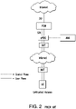
- Fig. 2 illustrates a conventional deployment for untrusted Wi-Fi access.
- Wi-Fi access network One problem with the conventional deployment of Wi-Fi access is extensive signaling in handover scenarios.
- the session on the other side is always taken down. For example, if the UE handovers a PDN connection from the LTE to WLAN using S2a/S2b to PGW, the LTE session in MME, SGW and PGW is removed and a new session for WLAN is created. If dedicated bearers are used on LTE, the PGW has to re-create them on WLAN access network. If the UE handovers to LTE, the WLAN session in the PGW is removed and a new LTE session is created in the MME, SGW and PGW.
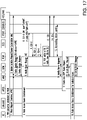
- Fig. 17 illustrates an example of the creation of bearers on the LTE side.
- the re-creation of bearers results in inefficient signaling. Additionally, the latency of the handover can be extensive.
- the PGW must use theS6b/Diameter interface when UE attach to WLAN to set the PGW id in HSS if handover is to be supported. Additionally, the S6b procedure towards HSS will also increase the HSS load. The S6b procedure also increases the AAA load.
- Another problem with the conventional deployment of Wi-Fi access is that no location information for untrusted access is available.
- untrusted WLAN when used, no location information is received on the S2b interface, which results in the PGW being unable report any valuable location information to the PCRF.
- Another problem with conventional deployment of Wi-Fi access is that the UE is in control of access selection.
- the PGW it is very hard for the PGW to perform access steering when S2a/S2b is used toward the PGW. For instance, if UE is connected to LTE and initiate a handover to WLAN. Then, theoretically the PGW can deny the attempt if UE have very good connectivity/user experience on LTE but the PGW do not have such information regarding the network condition on the LTE side. This is mainly due to that PGW is a gateway node serving many accesses and logically it shouldn't need information about the access network.
- a downstream mobile gateway comprises a forwarding unit and a service unit.
- the forwarding unit receives a packet that includes a destination address for a subscriber and a TEID.
- the service unit determines whether the TEID is associated with one of a number of subscriber records that store session data for current sessions associated with subscriber devices to communicate with the mobile network.
- the service unit In response to determining that the TEID is not associated with one of the subscriber records, the service unit generates a message that includes the TEID and the destination address and indicates that the downstream mobile gateway has determined that the TEID is not associated with one of the subscriber records.
- the forwarding unit then sends the message to the upstream mobile gateway.
- 3GPP TR 23.852 V12.0.0 2013-09
- 3rd Generation Partnership Project Technical Specification Group Services and System Aspects
- GTP GPRS Tunnelling Protocol
- WLAN Wireless Local Area Network
- Stage 2 discloses S2a mobility based on GTP and WLAN access to the EPC network.
- 3GPP TS 23.402 V12.6.0 2014-09
- 3rd Generation Partnership Project Technical Specification Group Services and System Aspects
- Architecture enhancements for non-3GPP accesses discloses architecture enhancements for non-3GPP accesses.
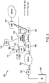
- Fig. 3 illustrates an embodiment of a wireless communication system 300.
- the wireless communication system 300 includes a UE 302 connected to an access point (AP) 304.
- the AP 304 is connected to an Internet network 306, which is connected to an evolved packet data gateway (ePDG).
- ePDG evolved packet data gateway
- the ePDG 308 is connected to an SGW 310, which is connected to a PGW 320.
- the system 300 further includes authentication, authorization, and accounting (AAA) servers 312 and 314, Home Subscriber Server (HSS) 316, and MME/SGSN 318.
- the UE 302 is a mobile device such as a smart phone or tablet device.
- a trusted wireless access gateway (TWAG) or the ePDG uses the S2a/S2b interface toward the MME node 318 instead of the PGW 320.
- the network may steer a UE to the same MME on both LTE and WI-FI access.
- the AAA can provide the information that resides in the HSS 316.
- Another mechanism may send one query to all MMEs in a pool asking about where the UE is registered.
- another mechanism can send a query to one MME which will then find out where the UE is registered, which may occur by sending queries to other MMEs in the pool.
- the MME 318 may re-use the LTE session and does not have to create a new session.
- the MME since the MME can re-use the LTE session, the MME only needs to trigger a Modify Bearer procedure to the SGW to update a downlink TEID to reaim a GTP-U tunnel from the eNB (or RNC in the case of 3G) to the TWAG/ePDG. From the SGW 310 and PGW 320 point of view, it follows the same procedure as Inter-RAT 3GPP handover.
- the MME may re-use the PDN session and triggers the Modify Bearer procedure to SGW (e.g., change GTP-U tunnel from TWAG/ePDG to eNB).
- SGW Modify Bearer
- any already created dedicated bearer (e.g., if UE have an ongoing VoLTE call) between SGW and PGW still remains upon handover, the MME only needs to set up the dedicated bearer at the new access based on its bearer contexts. Furthermore, because the MME is used both for LTE and Wi-Fi accesses, there is no need for PGW to use S6b signaling for updating the PGW Id and APN towards the AAA server (e.g., AAA server further updates HSS), which is used to ensure the same PGW is selected during the handover between LTE and Wi-Fi. MME will provide this function automatically from its PDN context.
- the AAA server e.g., AAA server further updates HSS
- the MME hides the ePDG/TWAN information from SGW and hide the SGW information from ePDG/TWAN so that SGW think that it is connected with an eNB on the user plane, and the ePDG/TWAG thinks that it is connected with a PGW on both control and user plane.
- the MME has location information knowledge for the UE when the UE resides in the LTE access.
- the MME can then use the LTE location information also when UE is in Wi-Fi. For example, when the UE has two PDN connections on LTE for the Internet and IMS, respectively, the UE handovers the IMS PDN connection to Wi-Fi but keeps Internet PDN connection on the LTE.
- the MME can use the 3GPP location information (e.g., ULI) for the PDN connection that is using Wi-Fi as access (i.e., IMS PDN connection in the above example) according to the current context if the UE is in 3GPP connected mode, or from the last time the UE was in 3GPP connected mode, or it can page the UE and get updated location information for the UE.
- This solution for location information is also valid if the UE sets up an initial PDN connection over Wi-Fi.
- the MME is in control for the UE for both LTE and Wi-Fi, and the MME has direct interfaces to both radio accesses.
- the MME can therefore be in control of access selection by declining the handover procedure from one access to another. For example, when the UE tries to do handover from LTE to Wi-Fi, the MME can query the LTE network about available user throughput on the LTE side and based on that make an access selection on behalf of the UE.
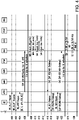
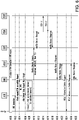
- Figs. 4 and 5 are a sequence diagram illustrating an embodiment for attaching to a Wi-Fi network.
- an IKEv2 access authentication procedure is performed (refer to Chapter 6.5 of TS 33.402 for details).
- the IKEv2 procedure may be performed in accordance with any authentication procedure known to one of ordinary skill in the art.
- the AAA server triggers a SLh LCS-RIR (refer to TS 29.173) or Sh Pull (refer to TS 29.329) procedure to retrieve the Identity of the MME on which the UE is registered currently.
- Another mechanism to get the identity is to send one query to all MMEs in a pool asking about where the UE is registered.
- a query is sent to one MME which will then find out where the UE is registered, which may occur by sending queries to other MMEs in the pool.
- the HSS returns the Identity (FQDN) or IP address of the MME on which the UE is registered currently according to SLh or Sh procedure.
- the AAA server builds the MME Identity for the S2b interface by adding, for example, a prefix (e.g., 'S2b') in front of the MME Id received from HSS, and sends DEA/EAP-Success message towards the ePDG.
- the PGW Identity field of the DEA/EAP-Success message is set to the MME identity for S2b interface built by the AAA server. If the UE is not registered in any MME in the visited network (e.g., UE detached from LTE access or have not registered in visited network), the AAA server can fallback to the standardized solution with PGW terminating S2b.
- the AAA server can detect from realm part of MME FQDN if the MME is in the visited or home network.
- steps 430 and 432 an IKEv2 access authentication procedure continues in accordance with any authentication procedure known to one of ordinary skill in the art.
- the ePDG regards the MME Id as the PGW Id for S2b interface and performs DNS query to g et the IP address of the MME.
- step 438 the ePDG sends Create Session Request to the MME as the normal GTPv2 S2b initial PDN connection setup request.
- step 440 the MME receives the Create Session Request for the GTPv2 S2b initial connection setup request, and then the MME selects a PGW based on the requested APN as the normal LTE initial PDN connection setup request.
- the MME hides the ePDG info from the SGW.
- the MME sets the values of the eNB-U F-TEID parameter in the Create Session Request to those of the ePDG-U F-TEID so that the user plane of ePDG and SGW can be connected. From the SGW point of view, its GTP user plane is connected with an eNB as the normal S1-U interface. There is no difference between GTP S1-U and S2b-U interface.
- GTP-U handling is the same for S1-U and S2b-U interface, where GTP-U packet format is the same for the S1-u and S2b-U.
- the MME sets the ULI parameter in the Create Session Request to the SGW according to the location information stored in the 3GPP registration context of the UE.
- the PGW receives the Create Session Request and performs an IP-CAN session establishment as defined in TS 23.203.
- the PGW accepts the PDN connection creation request and returns a Create Session Response with the UE IP address and other UE requested parameters (such as PCO).
- step 452 the SGW returns a Create Session Response to the MME with its user plane F-TEID parameters and the UE parameters returned by PGW.
- step 454 the MME sends back a Create Session Response with the UE IP address (and other PGW returned UE parameters) to the ePDG via S2b.
- step 456 the ePDG sends IKEv2 AUTH_RSP with the UE IP address (and other PGW returned UE parameters) as payload.
- the MME updates the HSS with the APN and the PGW Id by the standard S6a interface procedure between MME and HSS.
- the MME info is transparent to the ePDG. From the ePDG point of view, it is connected with a PGW.
- the MME shall set the values of the PGW-C F-TEID parameter in the Create Session Response to those of the MME-C F-TEID for S2b.
- the MME hides the SGW info from the ePDG.
- the MME shall set the values of the S2b PGW-U F-TEID parameter in the Create Session Response to those of the SGW-U F-TEID so that the user plane of the ePDG and SGW can be connected. From the ePDG point of view, its GTP user plane is connected as the normal S2b-U interface.
- Fig. 6 is a sequence diagram illustrating an embodiment for performing handover from a Wi-Fi connection to LTE.
- step 600 the UE has a PDN connection established over Wi-Fi access.
- the PDN connection may be established in accordance with steps illustrated in Figs. 4 and 5 .
- step 602 the UE decides to handover from Wi-Fi access to E-UTRAN.
- a RRC connection will be established between UE and eNB.
- step 604 the UE sends Attach request/PDN Connectivity Request with HO indication to MME via eNB. Based on the GUTI received from UE, the eNB will select the MME which holds the UE's E-UTRAN registration context, which is also the MME which is currently terminating the S2b interface for the UE at Wi-Fi access.
- the MME detects the handover request from non-3GPP. Since the MME has already established the PDN connection to the SGW and PGW for the UE at Wi-Fi access, the MME skips the PDN session creation procedure, and the MME also skips the HSS update procedure as the MME holds the UE's E-UTRAN registration context. Consequently, the MME will directly send an Attach Accept and trigger E-RAB establishment procedure based on the existing bearer contexts, such as QoS parameters, TFT and etc.
- step 608 E-RAB establishment procedure with both default and dedicated bearers is performed with the MME.
- step 610 after successful E-RAB establishment, the MME sends a Modify Bearer Request with Handover Indication, E-UTRAN RAT type and eNB user plane parameters to SGW as the Intra-3GPP IRAT handover procedure.
- step 612 the SGW forwards the Modify Bearer Request with Handover Indication to the PGW so that the PGW can update the RAT change to PCRF.
- PGW receives the Modify Bearer Request with Handover Indication and detects the RAT changed from WLAN to E-UTRAN.
- the PGW triggers PCC update procedure by sending CCR-U to PCRF.
- step 616 the PCRF replies with CCA-U. If there are some PCC rules update included in the CCA-U, the PGW will trigger Bearer Update procedure after the Bearer Modification procedure.
- the PGW follows the Intra-3GPP IRAT handover process and returns Modify Bearer Response to the SGW.
- step 620 the SGW forwards the Modify Bearer Response to the MME.
- the MME triggers the non-3GPP connection release to ePDG.
- Figs. 7 and 8 are a sequence diagram illustrating an embodiment for performing a handover from LTE to Wi-Fi.
- the UE has a PDN connection established over LTE access.
- the PDN connection over LTE access may be setup in accordance with any procedure known to one of ordinary skill in art for establishing a connection over LTE.
- an IKEv2 access authentication procedure is performed (refer to Chapter 6.5 of TS33.402 for details).
- the IKEv2 procedure may be performed in accordance with any authentication procedure known to one of ordinary skill in the art.
- the AAA server shall trigger a SLh LCS-RIR (refer to TS 29.173) or Sh Pull (refer to TS 29.329) procedure to retrieve the Identity of the MME on which the UE is registered currently.
- step 728 the HSS returns the Identity (FQDN) of the MME on which the UE is registered currently according to SLh or Sh procedure.
- the AAA builds the MME Identity for S2b interface by adding a prefix (e.g., 'S2b') in front of the MME Id received from HSS and sends DEA/EAP-Success message towards the ePDG.
- the PGW Identity field of the DEA/EAP-Success message is set to the MME identity for S2b interface built by the AAA server.
- steps 732 and 734 the IKEv2 access authentication procedure continues.
- the ePDG regards the MME Id as the PGW Id for S2b interface and performs DNS query to get the IP address of the MME.
- step 740 the ePDG sends Create Session Request with Handover Indication to the MME as the normal GTPv2 S2b handover request.
- step 742 the MME receives the Create Session Request with Handover Indication and detects that there is the corresponding PDN session context existed at LTE side.
- step 744 the MME acknowledges the handover by sending Create Session Response to the ePDG. If there are dedicated bearers to be created, MME shall piggyback the Create Bearer Request with the Create Session Response. If no dedicated bearer to be created, the step continues to step 748.
- the MME info is transparent to ePDG. For example, from the ePDG point of view, it is connected with a PGW.
- the MME sets the values of the PGW-C F-TEID parameter in the Create Session Response to those of the MME-C F-TEID for S2b.
- the MME hides the SGW info from the ePDG. Specifically, the MME sets the values of the PGW-U F-TEID parameter in the Create Session Response to those of the SGW-U F-TEID so that the user plane of ePDG and SGW can be connected. There is no difference between GTP S1-U and S2b-U interface since both use plain GTP-U.
- step 746 the ePDG sends the Create Bearer Response to the MME for the dedicated bearers.
- step 748 the ePDG sends IKEv2 AUTH_RSP to UE.
- step 748 may be performed at the same time as step 750.
- step 750 sine MME has already established the PDN connection to SGW and PGW for the UE at LTE access, the MME sends a Modify Bearer Request with Handover Indication and WLAN RAT type to the SGW as the Intra-3GPP IRAT handover procedure.
- the MME shall hide the ePDG info from the SGW so that SGW behaves as Intra-3GPP IRAT handover.
- the MME sets the values of the eNB-U F-TEID parameter in the Modify Bearer Request to those of the ePDG-U F-TEID so that the user plane of ePDG and SGW can be connected. From the SGW point of view, its user plane is connected with an eNB with normal S1-U interface.
- the MME sets the ULI parameter in the Modify Bearer Request to the SGW according to the current 3GPP location information stored in the PDN context of the UE.
- step 752 the SGW forwards the Modify Bearer Request with Handover Indication to the PGW so that the PGW can update the RAT change to PCRF.
- the PGW receives the Modify Bearer Request with Handover Indication and detects the RAT changed from E-UTRAN to WLAN.
- the PGW triggers PCC update procedure by sending CCR-U to PCRF.
- step 756 the PCRF replies with CCA-U. If there are some PCC rules update included in the CCA-U, the PGW will trigger Bearer Update procedure after the Bearer Modification procedure.
- the PGW follows the Intra-3GPP IRAT handover process and returns Modify Bearer Response to the SGW.
- step 760 The SGW forwards the Modify Bearer Response to the MME.
- Figs. 9A-9B is a sequence diagram illustrating an embodiments for performing handover from Wi-Fi to LTE when the UE is not registered on a target MME. This case may occur when the UE moves out the MME pool area or the source MME fails.
- the UE triggers a handover from non-3GPP to 3GPP.
- a target MME which doesn't host the UE S2b connection context is selected.
- the target MME follows the standard non-3GPP to 3GPP handover procedure.
- the MME will get the PGW Id from the HSS, then at step 910, the MME sends a Create Session Request with Handover Indication to the selected SGW.
- the PGW receives a Create Session Request with Handover Indication, then the PGW shall check whether there is an existing PDN context with non-3GPP RAT type (i.e., WLAN in this scenario) matching the IMSI and APN included in the Create Session Request. If there is such a matching found, the PGW shall follow the standard non-3GPP to 3GPP handover procedure.
- non-3GPP RAT type i.e., WLAN in this scenario
- the PGW continues the non-3GPP to 3GPP handover following the standard procedure.
- the PGW shall trigger the old PDN connection deletion on the non-3GPP (i.e., Wi-Fi access).
- Fig. 10 illustrates a process performed by a mobility management node such as the MME or SGSN.
- the process may start at 1000, where the mobility management node receives a first PDN activation request from a wireless local area network (WLAN) access gateway, and where the PDN activation request specifies an access point name (APN) and a TEID parameter for identifying the WLAN access gateway.
- the WLAN access gateway may be the ePDG or TWAG.
- the mobility management node selects a Packet Data Network Gateway (PGW) based on the specified APN, (ii) generates a second PDN activation request by setting a tunnel endpoint identifier (TEID) parameter of the request to identify the WLAN access gateway, (iii) selects a serving gateway (SGW), and (iv) and forwards the generated second PDN activation request to the selected SGW.
- PGW Packet Data Network Gateway
- SGW serving gateway
- Fig. 11 illustrates an embodiment of a process performed by a mobility management node.
- the mobility management node receives a first create session response from the selected SGW.
- the mobility management node generates a second create session response based on the first create session response for establishing a tunnel between the WLAN access gateway and the mobility management node, and a tunnel between the WLAN access point gateway and the SGW.
- the mobility management node forwarding the second create session response to the WLAN access gateway.
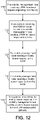
- Fig. 12 is a flow chart illustrating an embodiment of a process for performing handover from Wi-Fi to LTE or 3G.
- the mobility management node may be an MME or SGSN.
- the process may start at 1200, where the mobility management node receives attachment PDN handover request originating from the UE.
- the mobility management node in response to receiving the PDN handover request, the mobility management node sends attachment PDN handover response to the UE.
- the mobility management node sending a modify bearer request to the SGW.
- the mobility management node receiving a modify bearer response from the SGW.
- the mobility management node sends a delete bearer request to the WLAN access gateway.
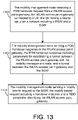
- Fig. 13 is a flow chart illustrating an embodiment of a process for performing handover from LTE or 3G to Wi-Fi.
- the mobility management node may be an MME or SGSN.
- the process may start at step 1300, where the mobility management node receives a PDN handover request from a wireless local area network (WLAN) access gateway, where, the WLAN access gateway is connected to a user equipment (UE), and the UE has a bearer setup on a network including a packet data network gateway (PGW) and a serving gateway (SGW).
- WLAN wireless local area network
- UE user equipment
- PGW packet data network gateway
- SGW serving gateway
- the mobility management node sends a PDN handover response to the WLAN access gateway, where the PDN handover response includes parameters for establishing a control plane tunnel between the WLAN access gateway and the mobility management node, and a user plane tunnel between the WLAN access gateway and the SGW.
- the mobility management node sends a modify bearer request to the SGW, where the modify bearer request includes a handover indicator and a tunnel endpoint identifier (TEID) parameter identifying the WLAN access gateway.
- TEID tunnel endpoint identifier
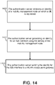
- Fig. 14 is a flow chart illustrating an embodiment of a process performed by an authentication server such as AAA 312.
- the method may start at step 1400 where the authentication server retrieves an identity of a mobility management node on which a user equipment (UE) is registered.
- the authentication server generates an identity for an S2b interface using the identity of the mobility management node.
- the authentication server sends the identity for the S2 interface to a wireless local area network (WLAN) access gateway.
- WLAN wireless local area network
- Fig. 15 is a block diagram of an embodiment of a network node such as the MME, SGSN, AAA, PGW, and SGW.
- the network node may include or consist of: a computer system (CS) 1502, which may include one or more processors 1555 (e.g., a general purpose microprocessor) and/or one or more circuits, such as an application specific integrated circuit (ASIC), field-programmable gate arrays (FPGAs), a logic circuit, and the like; a network interface 1503 for use in connecting the network node to a network; and a data storage system 1506, which may include one or more non-volatile storage devices and/or one or more volatile storage devices (e.g ., random access memory (RAM)).
- CS computer system
- processors 1555 e.g., a general purpose microprocessor
- ASIC application specific integrated circuit
- FPGAs field-programmable gate arrays
- a logic circuit e.g., a logic circuit, and the like
- CPP 1533 includes or is a computer readable medium (CRM) 1542 storing a computer program (CP) 1543 comprising computer readable instructions (CRI) 1544.
- CRM 1542 is a non-transitory computer readable medium, such as, but not limited, to magnetic media (e.g., a hard disk), optical media (e.g., a DVD), solid state devices (e.g ., random access memory (RAM), flash memory), and the like.
- the CRI 1444 of computer program 1543 is configured such that when executed by computer system 1502, the CRI causes the network node to perform steps described above (e.g ., steps described above with reference to the flow charts and message flows shown in the drawings).
- the network node may be configured to perform steps described herein without the need for a computer program. That is, for example, computer system 1502 may consist merely of one or more ASICs. Hence, the features of the embodiments described herein may be implemented in hardware and/or software.
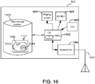
- Fig. 16 is a block diagram of UE 302 according to some embodiments.
- UE 302 may include or consist of: a computer system (CS) 1602, which may include one or more processors 1655 (e.g., a general purpose microprocessor) and/or one or more circuits, such as an application specific integrated circuit (ASIC), field-programmable gate arrays (FPGAs), a logic circuit, and the like; a transceiver 1605, coupled to an antenna, 1622 for transmitting and receiving data wireless; and a data storage system 1606, which may include one or more non-volatile storage devices and/or one or more volatile storage devices (e.g ., random access memory (RAM)).
- CS computer system
- processors 1655 e.g., a general purpose microprocessor
- ASIC application specific integrated circuit
- FPGAs field-programmable gate arrays
- a logic circuit e.g., a logic circuit, and the like
- transceiver 1605 coupled to an antenna, 1622
- CPP 1633 includes or is a computer readable medium (CRM) 1642 storing a computer program (CP) 1643 comprising computer readable instructions (CRI) 1644.
- CRM 1642 is a non-transitory computer readable medium, such as, but not limited, to magnetic media (e.g., a hard disk), optical media (e.g., a DVD), solid state devices (e.g., random access memory (RAM), flash memory), and the like.
- the CRI 1644 of computer program 1643 is configured such that when executed by computer system 1602, the CRI causes the UE 102 to perform steps described above (e.g. , steps described above with reference to the flow charts and message flows shown in the drawings).
- UE 102 may be configured to perform steps described herein without the need for a computer program. That is, for example, computer system 1502 may consist merely of one or more ASICs. Hence, the features of the embodiments described herein may be implemented in hardware and/or software.
- UE 302 may include: a display screen 1633, a speaker 1624, and a microphone ("mica"), all of which are coupled to CS 1602.
Landscapes
- Engineering & Computer Science (AREA)
- Computer Networks & Wireless Communication (AREA)
- Signal Processing (AREA)
- Computer Security & Cryptography (AREA)
- Mobile Radio Communication Systems (AREA)
Description
- Disclosed herein are, for example, methods and network nodes for reuse of EPC session between 3GPP and WLAN.
- Today, mobile operators are using Wi-Fi to offload traffic from the mobile networks. However, the opportunity to improve end user experience regarding performance is also becoming more important. The current Wi-Fi deployments are completely separate from mobile networks, and are to be seen as non-integrated. The usage of Wi-Fi is driven due to the free and wide unlicensed spectrum, and the increased availability of Wi-Fi in mobile terminals like smartphones and tablets. The end users are also becoming more and more at ease with using Wi-Fi for example at offices and homes.
- The different business segments for Wi-Fi regarding integration possibilities can be divided into mobile operator hosted/controlled vs. 3rd party hosted/controlled Wi-Fi Aps. As an example, a 3rd party is seen as any other entity other than mobile operator and that the 3rd party is not totally "trusted" by the mobile operator. The 3rd party could be for example a Wi-Fi operator or an end-user him/herself. In both segments, there exist public/hotspot, enterprise and residential deployments.
- Wi-Fi integration towards the mobile core network is emerging as a good way to improve the end user experience further. These solutions consist mainly of the components: common authentication between 3GPP and Wi-Fi, and integration of Wi-Fi user plane traffic to the mobile core network. The common authentication is based on automatic SIM-based authentication in both access types. The Wi-Fi user plane integration provides the mobile operator the opportunity to provide the same services such as parental control and subscription based payment methods for the end users when connected both via 3GPP and via Wi-Fi. Different solutions are standardized in 3GPP: Overlay solutions (S2b, S2c) and integration solutions (S2a) are specified in 3GPP (S2a, S2b, S2c indicating the 3GPP interface/reference point name towards the PDN-GW). These solutions are specified in 3GPP TS 23.402.
-
Fig. 1 shows the network architecture for E-UTRAN and EPC and how the eNodeB is connected via the S1-interfaces, S1-MME and S1-U to the MME and Serving GW respectively. It also shows how the Wi-Fi access network is connected to the PDN-GW via the S2a interface (that is trusted Wi-Fi access) and to the 3GPP AAA Server via the STa interface.Fig. 2 illustrates a conventional deployment for untrusted Wi-Fi access. - One problem with the conventional deployment of Wi-Fi access is extensive signaling in handover scenarios. In this regard, when UE handover occurs between LTE and Wi-Fi, the session on the other side is always taken down. For example, if the UE handovers a PDN connection from the LTE to WLAN using S2a/S2b to PGW, the LTE session in MME, SGW and PGW is removed and a new session for WLAN is created. If dedicated bearers are used on LTE, the PGW has to re-create them on WLAN access network. If the UE handovers to LTE, the WLAN session in the PGW is removed and a new LTE session is created in the MME, SGW and PGW. If dedicated bearers are used on the WLAN, the PGW have to re-create them on LTE.
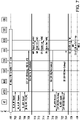
Fig. 17 illustrates an example of the creation of bearers on the LTE side. The re-creation of bearers results in inefficient signaling. Additionally, the latency of the handover can be extensive. Furthermore, the PGW must use theS6b/Diameter interface when UE attach to WLAN to set the PGW id in HSS if handover is to be supported. Additionally, the S6b procedure towards HSS will also increase the HSS load. The S6b procedure also increases the AAA load. - Another problem with the conventional deployment of Wi-Fi access is that no location information for untrusted access is available. In this regard, when untrusted WLAN is used, no location information is received on the S2b interface, which results in the PGW being unable report any valuable location information to the PCRF.
- Another problem with conventional deployment of Wi-Fi access is that the UE is in control of access selection. In this regard, it is very hard for the PGW to perform access steering when S2a/S2b is used toward the PGW. For instance, if UE is connected to LTE and initiate a handover to WLAN. Then, theoretically the PGW can deny the attempt if UE have very good connectivity/user experience on LTE but the PGW do not have such information regarding the network condition on the LTE side. This is mainly due to that PGW is a gateway node serving many accesses and logically it shouldn't need information about the access network.
-
US 8,855,071 B1 discloses techniques for handling errors in subscriber session management within mobile networks. A downstream mobile gateway comprises a forwarding unit and a service unit. The forwarding unit receives a packet that includes a destination address for a subscriber and a TEID. The service unit determines whether the TEID is associated with one of a number of subscriber records that store session data for current sessions associated with subscriber devices to communicate with the mobile network. In response to determining that the TEID is not associated with one of the subscriber records, the service unit generates a message that includes the TEID and the destination address and indicates that the downstream mobile gateway has determined that the TEID is not associated with one of the subscriber records. The forwarding unit then sends the message to the upstream mobile gateway. - 3GPP TR 23.852 V12.0.0 (2013-09), 3rd Generation Partnership Project; Technical Specification Group Services and System Aspects; Study on S2a Mobility based on GPRS Tunnelling Protocol (GTP) and Wireless Local Area Network (WLAN) access to the Enhanced Packet Core (EPC) network (SaMOG); Stage 2 (Release 12) discloses S2a mobility based on GTP and WLAN access to the EPC network.
- 3GPP TS 23.402 V12.6.0 (2014-09), 3rd Generation Partnership Project; Technical Specification Group Services and System Aspects; Architecture enhancements for non-3GPP accesses (Release 12) discloses architecture enhancements for non-3GPP accesses.
- The invention is set out in the appended set of claims.
- The accompanying drawings, which are incorporated herein and form part of the specification, illustrate various embodiments.
-
Fig. 1 illustrates a network architecture. -
Fig. 2 illustrates a deployment for untrusted Wi-Fi access -
Fig. 3 illustrates an exemplary wireless communication system according to some embodiments. -
Fig. 4 illustrates a sequence diagram according to some embodiments. -
Fig. 5 illustrates a sequence diagram according to some embodiments. -
Fig. 6 illustrates a sequence diagram according to some embodiments. -
Fig. 7 illustrates a sequence diagram according to some embodiments. -
Fig. 8 illustrates a sequence diagram according to some embodiments. -
Figs. 9A-9B illustrate a sequence diagram according to some embodiments. -
Fig. 10 is a flow chart illustrating a process according to some embodiments. -
Fig. 11 is a flow chart illustrating a process according to some embodiments. -
Fig. 12 is a flow chart illustrating a process according to some embodiments. -
Fig. 13 is a flow chart illustrating a process according to some embodiments. -
Fig. 14 is a flow chart illustrating a process according to some embodiments, not part of the invention. -
Fig. 15 is a block diagram of a network node according to some embodiments. -
Fig. 16 is a block diagram of a UE according to some embodiments. -
Fig. 17 is a sequence diagram illustrating creation of bearers. -
Fig. 3 illustrates an embodiment of awireless communication system 300. Thewireless communication system 300 includes aUE 302 connected to an access point (AP) 304. TheAP 304 is connected to anInternet network 306, which is connected to an evolved packet data gateway (ePDG). TheePDG 308 is connected to anSGW 310, which is connected to aPGW 320. Thesystem 300 further includes authentication, authorization, and accounting (AAA)servers SGSN 318. In some embodiments, theUE 302 is a mobile device such as a smart phone or tablet device. - In some embodiments, a trusted wireless access gateway (TWAG) or the ePDG uses the S2a/S2b interface toward the
MME node 318 instead of thePGW 320. Additionally, the network may steer a UE to the same MME on both LTE and WI-FI access. To direct the TWAG/ePDG to the correct MME node, the AAA can provide the information that resides in theHSS 316. Another mechanism may send one query to all MMEs in a pool asking about where the UE is registered. In some embodiments, another mechanism can send a query to one MME which will then find out where the UE is registered, which may occur by sending queries to other MMEs in the pool. - In some embodiments, when the
MME 318 receives a S2a/S2b GTPv2 create session request with a handover indicator, theMME 318 may re-use the LTE session and does not have to create a new session. In this regard, since the MME can re-use the LTE session, the MME only needs to trigger a Modify Bearer procedure to the SGW to update a downlink TEID to reaim a GTP-U tunnel from the eNB (or RNC in the case of 3G) to the TWAG/ePDG. From theSGW 310 andPGW 320 point of view, it follows the same procedure as Inter-RAT 3GPP handover. - In some embodiments, when there is a UE handover to LTE, the MME may re-use the PDN session and triggers the Modify Bearer procedure to SGW (e.g., change GTP-U tunnel from TWAG/ePDG to eNB).
- Because the SGW and PGW PDN session is re-used, any already created dedicated bearer (e.g., if UE have an ongoing VoLTE call) between SGW and PGW still remains upon handover, the MME only needs to set up the dedicated bearer at the new access based on its bearer contexts. Furthermore, because the MME is used both for LTE and Wi-Fi accesses, there is no need for PGW to use S6b signaling for updating the PGW Id and APN towards the AAA server (e.g., AAA server further updates HSS), which is used to ensure the same PGW is selected during the handover between LTE and Wi-Fi. MME will provide this function automatically from its PDN context.
- In some embodiments, the MME hides the ePDG/TWAN information from SGW and hide the SGW information from ePDG/TWAN so that SGW think that it is connected with an eNB on the user plane, and the ePDG/TWAG thinks that it is connected with a PGW on both control and user plane.
- In some embodiments, the MME has location information knowledge for the UE when the UE resides in the LTE access. The MME can then use the LTE location information also when UE is in Wi-Fi. For example, when the UE has two PDN connections on LTE for the Internet and IMS, respectively, the UE handovers the IMS PDN connection to Wi-Fi but keeps Internet PDN connection on the LTE. The MME can use the 3GPP location information (e.g., ULI) for the PDN connection that is using Wi-Fi as access (i.e., IMS PDN connection in the above example) according to the current context if the UE is in 3GPP connected mode, or from the last time the UE was in 3GPP connected mode, or it can page the UE and get updated location information for the UE. This solution for location information is also valid if the UE sets up an initial PDN connection over Wi-Fi.
- According to some embodiments, the MME is in control for the UE for both LTE and Wi-Fi, and the MME has direct interfaces to both radio accesses. The MME can therefore be in control of access selection by declining the handover procedure from one access to another. For example, when the UE tries to do handover from LTE to Wi-Fi, the MME can query the LTE network about available user throughput on the LTE side and based on that make an access selection on behalf of the UE.
- These embodiments are applicable for S4-SGSN and 3G connections. These embodiments are also applicable to all non-3GPP accesses (including trusted Wi-Fi) supporting handover between 3GPP and non-3GPP.
-
Figs. 4 and5 are a sequence diagram illustrating an embodiment for attaching to a Wi-Fi network. - In steps 400-422, an IKEv2 access authentication procedure is performed (refer to Chapter 6.5 of TS 33.402 for details). The IKEv2 procedure may be performed in accordance with any authentication procedure known to one of ordinary skill in the art.
- In
step 424, the AAA server triggers a SLh LCS-RIR (refer to TS 29.173) or Sh Pull (refer to TS 29.329) procedure to retrieve the Identity of the MME on which the UE is registered currently. Another mechanism to get the identity is to send one query to all MMEs in a pool asking about where the UE is registered. In another mechanism to get the identity, a query is sent to one MME which will then find out where the UE is registered, which may occur by sending queries to other MMEs in the pool. - In
step 426, the HSS returns the Identity (FQDN) or IP address of the MME on which the UE is registered currently according to SLh or Sh procedure. - In
step 428, the AAA server builds the MME Identity for the S2b interface by adding, for example, a prefix (e.g., 'S2b') in front of the MME Id received from HSS, and sends DEA/EAP-Success message towards the ePDG. The PGW Identity field of the DEA/EAP-Success message is set to the MME identity for S2b interface built by the AAA server. If the UE is not registered in any MME in the visited network (e.g., UE detached from LTE access or have not registered in visited network), the AAA server can fallback to the standardized solution with PGW terminating S2b. The AAA server can detect from realm part of MME FQDN if the MME is in the visited or home network. - In
steps - In
steps - In
step 438, the ePDG sends Create Session Request to the MME as the normal GTPv2 S2b initial PDN connection setup request. - In
step 440, the MME receives the Create Session Request for the GTPv2 S2b initial connection setup request, and then the MME selects a PGW based on the requested APN as the normal LTE initial PDN connection setup request. - In
step 442, the MME selects a SGW as the LTE initial attach and sends the Create Session Request with RAT type = WLAN to the SGW via S11 interface. In some embodiments, the MME hides the ePDG info from the SGW. For example, the MME sets the values of the eNB-U F-TEID parameter in the Create Session Request to those of the ePDG-U F-TEID so that the user plane of ePDG and SGW can be connected. From the SGW point of view, its GTP user plane is connected with an eNB as the normal S1-U interface. There is no difference between GTP S1-U and S2b-U interface. In this regard, for example, GTP-U handling is the same for S1-U and S2b-U interface, where GTP-U packet format is the same for the S1-u and S2b-U. In some embodiments, the MME sets the ULI parameter in the Create Session Request to the SGW according to the location information stored in the 3GPP registration context of the UE. - In
step 444, the SGW further sends a Create Session Request with RAT type = WLAN to the PGW via S5/S8 interface. - In
steps - In
step 450, the PGW accepts the PDN connection creation request and returns a Create Session Response with the UE IP address and other UE requested parameters (such as PCO). - In
step 452, the SGW returns a Create Session Response to the MME with its user plane F-TEID parameters and the UE parameters returned by PGW. - In
step 454, the MME sends back a Create Session Response with the UE IP address (and other PGW returned UE parameters) to the ePDG via S2b. - In
step 456, the ePDG sends IKEv2 AUTH_RSP with the UE IP address (and other PGW returned UE parameters) as payload. - In
steps -
Fig. 6 is a sequence diagram illustrating an embodiment for performing handover from a Wi-Fi connection to LTE. - In
step 600, the UE has a PDN connection established over Wi-Fi access. The PDN connection may be established in accordance with steps illustrated inFigs. 4 and5 . - In
step 602, the UE decides to handover from Wi-Fi access to E-UTRAN. A RRC connection will be established between UE and eNB. - In
step 604, the UE sends Attach request/PDN Connectivity Request with HO indication to MME via eNB. Based on the GUTI received from UE, the eNB will select the MME which holds the UE's E-UTRAN registration context, which is also the MME which is currently terminating the S2b interface for the UE at Wi-Fi access. - In
step 606, the MME detects the handover request from non-3GPP. Since the MME has already established the PDN connection to the SGW and PGW for the UE at Wi-Fi access, the MME skips the PDN session creation procedure, and the MME also skips the HSS update procedure as the MME holds the UE's E-UTRAN registration context. Consequently, the MME will directly send an Attach Accept and trigger E-RAB establishment procedure based on the existing bearer contexts, such as QoS parameters, TFT and etc. - In
step 608, E-RAB establishment procedure with both default and dedicated bearers is performed with the MME. - In
step 610, after successful E-RAB establishment, the MME sends a Modify Bearer Request with Handover Indication, E-UTRAN RAT type and eNB user plane parameters to SGW as the Intra-3GPP IRAT handover procedure. - In
step 612, the SGW forwards the Modify Bearer Request with Handover Indication to the PGW so that the PGW can update the RAT change to PCRF. - In
step 614, PGW receives the Modify Bearer Request with Handover Indication and detects the RAT changed from WLAN to E-UTRAN. The PGW triggers PCC update procedure by sending CCR-U to PCRF. - In
step 616, the PCRF replies with CCA-U. If there are some PCC rules update included in the CCA-U, the PGW will trigger Bearer Update procedure after the Bearer Modification procedure. - In
step 618, the PGW follows the Intra-3GPP IRAT handover process and returns Modify Bearer Response to the SGW. - In
step 620, the SGW forwards the Modify Bearer Response to the MME. - In steps 622-628, the MME triggers the non-3GPP connection release to ePDG.
-
Figs. 7 and8 are a sequence diagram illustrating an embodiment for performing a handover from LTE to Wi-Fi. - In
step 700, the UE has a PDN connection established over LTE access. The PDN connection over LTE access may be setup in accordance with any procedure known to one of ordinary skill in art for establishing a connection over LTE. - In steps 702-724, an IKEv2 access authentication procedure is performed (refer to Chapter 6.5 of TS33.402 for details). The IKEv2 procedure may be performed in accordance with any authentication procedure known to one of ordinary skill in the art.
- In
step 726, the AAA server shall trigger a SLh LCS-RIR (refer to TS 29.173) or Sh Pull (refer to TS 29.329) procedure to retrieve the Identity of the MME on which the UE is registered currently. - In
step 728, the HSS returns the Identity (FQDN) of the MME on which the UE is registered currently according to SLh or Sh procedure. - In
step 730, the AAA builds the MME Identity for S2b interface by adding a prefix (e.g., 'S2b') in front of the MME Id received from HSS and sends DEA/EAP-Success message towards the ePDG. The PGW Identity field of the DEA/EAP-Success message is set to the MME identity for S2b interface built by the AAA server. - In
steps - In
steps - In
step 740, the ePDG sends Create Session Request with Handover Indication to the MME as the normal GTPv2 S2b handover request. - In
step 742, the MME receives the Create Session Request with Handover Indication and detects that there is the corresponding PDN session context existed at LTE side. - In
step 744, the MME acknowledges the handover by sending Create Session Response to the ePDG. If there are dedicated bearers to be created, MME shall piggyback the Create Bearer Request with the Create Session Response. If no dedicated bearer to be created, the step continues to step 748. - In some embodiments, the MME info is transparent to ePDG. For example, from the ePDG point of view, it is connected with a PGW. The MME sets the values of the PGW-C F-TEID parameter in the Create Session Response to those of the MME-C F-TEID for S2b. In some embodiments, the MME hides the SGW info from the ePDG. Specifically, the MME sets the values of the PGW-U F-TEID parameter in the Create Session Response to those of the SGW-U F-TEID so that the user plane of ePDG and SGW can be connected. There is no difference between GTP S1-U and S2b-U interface since both use plain GTP-U.
- In
step 746, the ePDG sends the Create Bearer Response to the MME for the dedicated bearers. - In step 748, the ePDG sends IKEv2 AUTH_RSP to UE. In some embodiments, step 748 may be performed at the same time as step 750.
- In step 750, sine MME has already established the PDN connection to SGW and PGW for the UE at LTE access, the MME sends a Modify Bearer Request with Handover Indication and WLAN RAT type to the SGW as the Intra-3GPP IRAT handover procedure. In some embodiments, the MME shall hide the ePDG info from the SGW so that SGW behaves as Intra-3GPP IRAT handover. Specifically, the MME sets the values of the eNB-U F-TEID parameter in the Modify Bearer Request to those of the ePDG-U F-TEID so that the user plane of ePDG and SGW can be connected. From the SGW point of view, its user plane is connected with an eNB with normal S1-U interface. In some embodiments, the MME sets the ULI parameter in the Modify Bearer Request to the SGW according to the current 3GPP location information stored in the PDN context of the UE.
- In
step 752, the SGW forwards the Modify Bearer Request with Handover Indication to the PGW so that the PGW can update the RAT change to PCRF. - In
step 754, the PGW receives the Modify Bearer Request with Handover Indication and detects the RAT changed from E-UTRAN to WLAN. The PGW triggers PCC update procedure by sending CCR-U to PCRF. - In
step 756, the PCRF replies with CCA-U. If there are some PCC rules update included in the CCA-U, the PGW will trigger Bearer Update procedure after the Bearer Modification procedure. - In
step 758, The PGW follows the Intra-3GPP IRAT handover process and returns Modify Bearer Response to the SGW. - In
step 760, The SGW forwards the Modify Bearer Response to the MME. -
Figs. 9A-9B is a sequence diagram illustrating an embodiments for performing handover from Wi-Fi to LTE when the UE is not registered on a target MME. This case may occur when the UE moves out the MME pool area or the source MME fails. - In steps 900-910, the UE triggers a handover from non-3GPP to 3GPP. A target MME which doesn't host the UE S2b connection context is selected. The target MME follows the standard non-3GPP to 3GPP handover procedure. At
step 908, the MME will get the PGW Id from the HSS, then atstep 910, the MME sends a Create Session Request with Handover Indication to the selected SGW. - In
step 912, the PGW receives a Create Session Request with Handover Indication, then the PGW shall check whether there is an existing PDN context with non-3GPP RAT type (i.e., WLAN in this scenario) matching the IMSI and APN included in the Create Session Request. If there is such a matching found, the PGW shall follow the standard non-3GPP to 3GPP handover procedure. - In steps 914-932, the PGW continues the non-3GPP to 3GPP handover following the standard procedure.
- In
steps 934 to 948, the PGW shall trigger the old PDN connection deletion on the non-3GPP (i.e., Wi-Fi access). -
Fig. 10 illustrates a process performed by a mobility management node such as the MME or SGSN. The process may start at 1000, where the mobility management node receives a first PDN activation request from a wireless local area network (WLAN) access gateway, and where the PDN activation request specifies an access point name (APN) and a TEID parameter for identifying the WLAN access gateway. The WLAN access gateway may be the ePDG or TWAG. Atstep 1002, in response to receiving the PDN activation request, the mobility management node (i) selects a Packet Data Network Gateway (PGW) based on the specified APN, (ii) generates a second PDN activation request by setting a tunnel endpoint identifier (TEID) parameter of the request to identify the WLAN access gateway, (iii) selects a serving gateway (SGW), and (iv) and forwards the generated second PDN activation request to the selected SGW. -
Fig. 11 illustrates an embodiment of a process performed by a mobility management node. Instep 1100, the mobility management node receives a first create session response from the selected SGW. Instep 1102, the mobility management node generates a second create session response based on the first create session response for establishing a tunnel between the WLAN access gateway and the mobility management node, and a tunnel between the WLAN access point gateway and the SGW. Instep 1104, the mobility management node forwarding the second create session response to the WLAN access gateway. -
Fig. 12 is a flow chart illustrating an embodiment of a process for performing handover from Wi-Fi to LTE or 3G. The mobility management node may be an MME or SGSN. The process may start at 1200, where the mobility management node receives attachment PDN handover request originating from the UE. Atstep 1202, in response to receiving the PDN handover request, the mobility management node sends attachment PDN handover response to the UE. Instep 1204, the mobility management node sending a modify bearer request to the SGW. Instep 1206, the mobility management node receiving a modify bearer response from the SGW. Instep 1208, in response to receiving the modify bearer response, the mobility management node sends a delete bearer request to the WLAN access gateway. -
Fig. 13 is a flow chart illustrating an embodiment of a process for performing handover from LTE or 3G to Wi-Fi. The mobility management node may be an MME or SGSN. The process may start atstep 1300, where the mobility management node receives a PDN handover request from a wireless local area network (WLAN) access gateway, where, the WLAN access gateway is connected to a user equipment (UE), and the UE has a bearer setup on a network including a packet data network gateway (PGW) and a serving gateway (SGW). Instep 1302, the mobility management node sends a PDN handover response to the WLAN access gateway, where the PDN handover response includes parameters for establishing a control plane tunnel between the WLAN access gateway and the mobility management node, and a user plane tunnel between the WLAN access gateway and the SGW. Instep 1304, the mobility management node sends a modify bearer request to the SGW, where the modify bearer request includes a handover indicator and a tunnel endpoint identifier (TEID) parameter identifying the WLAN access gateway. -
Fig. 14 , not part of the invention, is a flow chart illustrating an embodiment of a process performed by an authentication server such asAAA 312. The method may start atstep 1400 where the authentication server retrieves an identity of a mobility management node on which a user equipment (UE) is registered. Instep 1402, the authentication server generates an identity for an S2b interface using the identity of the mobility management node. Instep 1404, the authentication server sends the identity for the S2 interface to a wireless local area network (WLAN) access gateway. -
Fig. 15 is a block diagram of an embodiment of a network node such as the MME, SGSN, AAA, PGW, and SGW. As shown inFig. 15 , the network node may include or consist of: a computer system (CS) 1502, which may include one or more processors 1555 (e.g., a general purpose microprocessor) and/or one or more circuits, such as an application specific integrated circuit (ASIC), field-programmable gate arrays (FPGAs), a logic circuit, and the like; anetwork interface 1503 for use in connecting the network node to a network; and adata storage system 1506, which may include one or more non-volatile storage devices and/or one or more volatile storage devices (e.g., random access memory (RAM)). In embodiments where the network node includes aprocessor 1555, a computer program product (CPP) 1433 may be provided.CPP 1533 includes or is a computer readable medium (CRM) 1542 storing a computer program (CP) 1543 comprising computer readable instructions (CRI) 1544.CRM 1542 is a non-transitory computer readable medium, such as, but not limited, to magnetic media (e.g., a hard disk), optical media (e.g., a DVD), solid state devices (e.g., random access memory (RAM), flash memory), and the like. In some embodiments, the CRI 1444 ofcomputer program 1543 is configured such that when executed bycomputer system 1502, the CRI causes the network node to perform steps described above (e.g., steps described above with reference to the flow charts and message flows shown in the drawings). In other embodiments, the network node may be configured to perform steps described herein without the need for a computer program. That is, for example,computer system 1502 may consist merely of one or more ASICs. Hence, the features of the embodiments described herein may be implemented in hardware and/or software. -
Fig. 16 is a block diagram ofUE 302 according to some embodiments. As shown inFig. 16 ,UE 302 may include or consist of: a computer system (CS) 1602, which may include one or more processors 1655 (e.g., a general purpose microprocessor) and/or one or more circuits, such as an application specific integrated circuit (ASIC), field-programmable gate arrays (FPGAs), a logic circuit, and the like; atransceiver 1605, coupled to an antenna, 1622 for transmitting and receiving data wireless; and adata storage system 1606, which may include one or more non-volatile storage devices and/or one or more volatile storage devices (e.g., random access memory (RAM)). In embodiments where UE 102 includes aprocessor 1655, a computer program product (CPP) 1633 may be provided.CPP 1633 includes or is a computer readable medium (CRM) 1642 storing a computer program (CP) 1643 comprising computer readable instructions (CRI) 1644.CRM 1642 is a non-transitory computer readable medium, such as, but not limited, to magnetic media (e.g., a hard disk), optical media (e.g., a DVD), solid state devices (e.g., random access memory (RAM), flash memory), and the like. In some embodiments, theCRI 1644 ofcomputer program 1643 is configured such that when executed bycomputer system 1602, the CRI causes the UE 102 to perform steps described above (e.g., steps described above with reference to the flow charts and message flows shown in the drawings). In other embodiments, UE 102 may be configured to perform steps described herein without the need for a computer program. That is, for example,computer system 1502 may consist merely of one or more ASICs. Hence, the features of the embodiments described herein may be implemented in hardware and/or software. As shown inFig. 16 ,UE 302 may include: adisplay screen 1633, aspeaker 1624, and a microphone ("mica"), all of which are coupled toCS 1602. - While various embodiments of the present disclosure are described herein, it should be understood that they have been presented by way of example only, and not limitation. Thus, the breadth and scope of the present disclosure should not be limited by any of the above-described exemplary embodiments. Moreover, any combination of the above-described elements in all possible variations thereof is encompassed by the disclosure unless otherwise indicated herein or otherwise clearly contradicted by context.
- Additionally, while the processes described above and illustrated in the drawings are shown as a sequence of steps, this was done solely for the sake of illustration. Accordingly, it is contemplated that some steps may be added, some steps may be omitted, the order of the steps may be re-arranged, and some steps may be performed in parallel.
-
- AAA
- Authentication, Authorization, and Accounting
- APN
- Access Point Name
- EPC
- Evolved Packet Core
- E-UTRAN
- Evolved Universal Terrestrial Radio Access Network
- ePDG
- Evolved Packet Data Gateway
- GPRS
- General Packet Radio Service
- IMS
- Internet Protocol Multimedia Subsystem
- LTE
- Long Term Evolution
- MME
- Mobility Management Entity
- PDN
- Packet Data Network
- PGW
- PDN Gateway
- SGSN
- GPRS Support Node
- SGW
- Serving Gateway Node
- TWAG
- Trusted Wireless Access Gateway
- UE
- User Equipment
- WLAN
- Wireless Local Area Network
Claims (13)
- A method performed in a mobility management node (318), the method comprising:the mobility management node (318) receiving (1000) a first Packet Data Network, PDN, activation request from a wireless local area network, WLAN, access gateway (308), the first PDN activation request specifying an access point name, APN, and a tunnel endpoint identifier, TEID, parameter for identifying the WLAN access gateway (308), the WLAN access gateway (308) connected to a user equipment, UE, (302); andin response to receiving the PDN activation request (1002), the mobility management node (318)(i) selecting a Packet Data Network Gateway, PGW, (320) based on the specified APN,(ii) generating a second PDN activation request that includes the TEID parameter for identifying the WLAN access gateway (308),(iii) selecting a serving gateway, SGW, (310), and(iv) forwarding the second PDN activation request to the selected SGW (310),wherein including the TEID parameter for identifying the WLAN access gateway (308) comprises setting values of an eNB-User plane, eNB-U, Fully-TEID, F-TEID, parameter; andwherein the first and second PDN activation requests are create session request messages.
- The method according to claim 1, further comprising:the mobility management node (318) receiving (1100) a first create session response from the selected SGW (310),the mobility management node (318) generating (1102) a second create session response based on the first create session response for establishing a control plane tunnel between the WLAN access gateway (308) and the mobility management node (308), and a user plane tunnel between the WLAN access gateway (308) and the SGW (310); andthe mobility management node (318) forwarding (1104) the second create session response to the WLAN access gateway (308).
- The method according to claim 2, further comprising:the mobility management node (318) receiving (1200) a PDN handover request originated from the UE (302);in response to receiving the PDN handover request, the mobility management node (318) sending (1202) PDN handover response to the UE (302);the mobility management node (318) sending (1204) a modify bearer request to the SGW (310);the mobility management node (318) receiving (1206) a modify bearer response from the SGW (310); andin response to receiving the modify bearer response, the mobility management node (318) sending (1208) a delete bearer request to the WLAN access gateway (308).
- The method according to claim 1, wherein the mobility management node (318) sets a user location information parameter in the second PDN activation request in accordance with location information stored in a 3GPP registration context of the UE (302).
- The method according to claim 1, whereinthe WLAN access gateway (308) is one of: an evolved Packet Data Gateway, ePDG, and a Trusted Wireless Access Gateway, TWAG, andthe mobility management node (318) is one of: a mobility management entity, MME, and a serving GPRS support node, SGSN.
- The method according to claim 3, whereinthe PDN handover request is an attachment request with a handover indicator, andthe first and second PDN activation requests are create session request messages.
- A mobility management node (318) comprising:a processor (1502); anda computer readable medium (1533) coupled to the processor (1502), said computer readable medium containing instructions (1544) which when executed by the processor (1502), cause the mobility management node (318) to perform:receive (1000) a first Packet Data Network, PDN, activation request from a wireless local area network, WLAN, access gateway (308), the first PDN activation request specifying an access point name, APN, and a tunnel endpoint identifier, TEID, parameter for identifying the WLAN access gateway (308), the WLAN access gateway (308) connected to a user equipment, UE, (302), andin response to receiving the PDN activation request (1002),(i) select a Packet Data Network Gateway, PGW, (320) based on the specified APN,(ii) generate a second PDN activation request that includes the TEID parameter for identifying the WLAN access gateway (308),(iii) select a serving gateway, SGW, (310), and(iv) forward the second PDN activation request to the selected SGW (310),wherein including the TEID parameter for identifying the WLAN access gateway (308) comprises setting values of an eNB-User plane, eNB-U, Fully-TEID, F-TEID, parameter,wherein the first and second PDN activation requests are create session request messages.
- The mobility management node (318) according to claim 7, wherein the mobility management node (318) is further configured to:receive (1100) a first create session response from the selected SGW (310),generate (1102) a second create session response based on the first create session response for establishing a control plane tunnel between the WLAN access gateway (308) and the mobility management node (318), and a user plane tunnel between the WLAN access gateway (308) and the SGW (310), andforward (1104) the second create session response to the WLAN access gateway (308).
- The mobility management node (318) according to claim 8, wherein the mobility management node (318) is configured to generate the second create session response by (i) setting a TEID parameter specified for the PGW-C S2b or S2a to the mobility management node (318), and (ii) setting a TEID parameter specified for the PGW-U S2b or S2a to the SGW-U.
- The mobility management node (318) according to claim 8, wherein the mobility management node (318) is configured to:receive (1200) a PDN handover request originating from the UE (302),in response to receiving the PDN handover request, send (1202) a PDN handover response to the UE (302),send (1204) a modify bearer request to the SGW (310),receive (1206) a modify bearer response from the SGW (310), andin response to receiving the modify bearer response, send (1208) a delete bearer request to the WLAN access gateway (308).
- The mobility management node (318) according to claim 7, wherein the mobility management node (318) is configured to set a user location information parameter in the second PDN activation request in accordance with location information stored in a 3GPP registration context of the UE (302).
- The mobility management node (318) according to claim 7, whereinthe first create session response includes one or more UE parameters,the WLAN access gateway (308) is one of: an evolved Packet Data Gateway, ePDG, and a Trusted Wireless Access Gateway, TWAG,the mobility management node (318) is one of: a mobility management entity, MME, and a serving GPRS support node, SGSN.
- The mobility management node (318) according to claim 10, whereinthe PDN handover request is an attachment request with a handover indicator, andthe first and second PDN activation requests are create session request messages.
Applications Claiming Priority (2)
| Application Number | Priority Date | Filing Date | Title |
|---|---|---|---|
| US201462064133P | 2014-10-15 | 2014-10-15 | |
| PCT/EP2015/073771 WO2016059109A2 (en) | 2014-10-15 | 2015-10-14 | Methods and network nodes for reuse of epc session between 3gpp and wlan |
Publications (2)
| Publication Number | Publication Date |
|---|---|
| EP3207744A2 EP3207744A2 (en) | 2017-08-23 |
| EP3207744B1 true EP3207744B1 (en) | 2022-09-07 |
Family
ID=54329523
Family Applications (1)
| Application Number | Title | Priority Date | Filing Date |
|---|---|---|---|
| EP15781339.5A Active EP3207744B1 (en) | 2014-10-15 | 2015-10-14 | Methods and network nodes for reuse of epc session between 3gpp and wlan |
Country Status (3)
| Country | Link |
|---|---|
| US (1) | US10721664B2 (en) |
| EP (1) | EP3207744B1 (en) |
| WO (1) | WO2016059109A2 (en) |
Families Citing this family (10)
| Publication number | Priority date | Publication date | Assignee | Title |
|---|---|---|---|---|
| CN105409285B (en) * | 2014-06-12 | 2019-11-22 | 华为技术有限公司 | A kind of equipment and control method of control carrying switching |
| CN107079287B (en) * | 2014-06-23 | 2020-03-27 | 康维达无线有限责任公司 | Inter-system mobility in integrated wireless networks |
| WO2016155012A1 (en) * | 2015-04-03 | 2016-10-06 | 华为技术有限公司 | Access method in wireless communication network, related device and system |
| EP3913867A1 (en) * | 2016-01-15 | 2021-11-24 | NEC Corporation | Communication system and communication method |
| KR102088717B1 (en) * | 2016-04-08 | 2020-03-13 | 한국전자통신연구원 | Non access stratum based access method and terminal supporting the same |
| US10419994B2 (en) * | 2016-04-08 | 2019-09-17 | Electronics And Telecommunications Research Institute | Non-access stratum based access method and terminal supporting the same |
| EP3461175B1 (en) | 2016-06-08 | 2020-07-08 | Huawei Technologies Co., Ltd. | Method, apparatus and system for establishing user-plane bearer |
| CN108307530B (en) * | 2016-09-30 | 2023-09-22 | 华为技术有限公司 | Session connection establishment method, related equipment and system |
| CN110121216B (en) * | 2018-02-05 | 2021-06-22 | 大唐移动通信设备有限公司 | Session recovery method and device and computer storage medium |
| GB201806430D0 (en) | 2018-04-20 | 2018-06-06 | Attocore Ltd | Peer discovery in distributed epc |
Family Cites Families (8)
| Publication number | Priority date | Publication date | Assignee | Title |
|---|---|---|---|---|
| CN101227714B (en) * | 2007-01-18 | 2011-04-06 | 华为技术有限公司 | System, apparatus and method for sharing network resource |
| CN102695294B (en) | 2007-05-28 | 2015-01-21 | 华为技术有限公司 | Network anchor point address deleting method and communication system |
| EP2422577B1 (en) * | 2009-04-23 | 2015-03-25 | Telefonaktiebolaget LM Ericsson (publ) | Local ip access through a femto base station |
| CN102308614B (en) * | 2011-07-01 | 2014-04-02 | 华为技术有限公司 | Bearing processing method and device |
| EP2761971A1 (en) * | 2011-09-30 | 2014-08-06 | Nokia Solutions and Networks Oy | Mobile relay support in relay-enhanced access networks |
| US8855071B1 (en) | 2012-01-04 | 2014-10-07 | Juniper Networks, Inc. | Handling errors in subscriber session management within mobile networks |
| WO2014003348A1 (en) * | 2012-06-24 | 2014-01-03 | 엘지전자 주식회사 | Method and device for supporting sipto for each ip flow in local network |
| CN107079287B (en) * | 2014-06-23 | 2020-03-27 | 康维达无线有限责任公司 | Inter-system mobility in integrated wireless networks |
-
2015
- 2015-10-14 US US15/518,436 patent/US10721664B2/en active Active
- 2015-10-14 EP EP15781339.5A patent/EP3207744B1/en active Active
- 2015-10-14 WO PCT/EP2015/073771 patent/WO2016059109A2/en active Application Filing
Also Published As
| Publication number | Publication date |
|---|---|
| WO2016059109A2 (en) | 2016-04-21 |
| US10721664B2 (en) | 2020-07-21 |
| EP3207744A2 (en) | 2017-08-23 |
| WO2016059109A3 (en) | 2016-06-09 |
| US20170332296A1 (en) | 2017-11-16 |
Similar Documents
| Publication | Publication Date | Title |
|---|---|---|
| EP3207744B1 (en) | Methods and network nodes for reuse of epc session between 3gpp and wlan | |
| US11785454B2 (en) | Terminal apparatus, base station apparatus, mobility management entity (MME), and communication control method | |
| US9706530B2 (en) | Communication system, method, and apparatus | |
| US9408113B2 (en) | Methods of and nodes for selecting a target core network for handing over a voice session of a terminal | |
| KR101105259B1 (en) | Method, system and device for supporting addressing the user static ip address in long term evolution system | |
| US9699635B2 (en) | Methods and devices for facilitating emergency calls over wireless communication systems | |
| EP3364674B1 (en) | Voice roaming method, mobility management network element, and access network element | |
| EP2291014A1 (en) | Method and corresponding terminal for association relationship updating | |
| US20120224564A1 (en) | Method and system to support single radio video call continuity during handover | |
| US8666419B1 (en) | Method and apparatus for performing a handover between a non 3GPP access and a 3GPP access using Gn/Gp SGSNs | |
| US8582503B2 (en) | Method for indicating the bearer management of a serving gateway | |
| US9930579B2 (en) | Method and nodes for providing handover management | |
| EP3291605A1 (en) | Communication method, communication system, base station for mobile communication, and communication apparatus for wireless lan | |
| EP2209279B1 (en) | Method and system for processing a radio bearer under the idle mode signaling reduction (isr) mechanism | |
| EP3017631B1 (en) | Connecting to radio access networks selected based on charging data for a subscription of a user | |
| US20150304908A1 (en) | Method, apparatus, and system for selecting pdn gateway | |
| WO2014194672A1 (en) | Method and device for inter-system reselection or switching processing | |
| US20150237495A1 (en) | Method and system for differentiating between subscribers | |
| KR20150099367A (en) | Method and apparatus for improving service quality of video call in mobile communication systems | |
| US11729739B2 (en) | Support of WLAN location change reporting or retrieval for untrusted WLAN access to a 3GPP packet core network | |
| CN109842879B (en) | Call switching method and device | |
| WO2021013353A1 (en) | Fallback during call set-up | |
| WO2021104465A1 (en) | Method and apparatus for pdn connection management | |
| KR20150035145A (en) | Authentication apparatus in wireless communication system, method thereof and computer recordable medium storing the method |
Legal Events
| Date | Code | Title | Description |
|---|---|---|---|
| STAA | Information on the status of an ep patent application or granted ep patent |
Free format text: STATUS: THE INTERNATIONAL PUBLICATION HAS BEEN MADE |
|
| PUAI | Public reference made under article 153(3) epc to a published international application that has entered the european phase |
Free format text: ORIGINAL CODE: 0009012 |
|
| STAA | Information on the status of an ep patent application or granted ep patent |
Free format text: STATUS: REQUEST FOR EXAMINATION WAS MADE |
|
| 17P | Request for examination filed |
Effective date: 20170503 |
|
| AK | Designated contracting states |
Kind code of ref document: A2 Designated state(s): AL AT BE BG CH CY CZ DE DK EE ES FI FR GB GR HR HU IE IS IT LI LT LU LV MC MK MT NL NO PL PT RO RS SE SI SK SM TR |
|
| AX | Request for extension of the european patent |
Extension state: BA ME |
|
| DAV | Request for validation of the european patent (deleted) | ||
| DAX | Request for extension of the european patent (deleted) | ||
| STAA | Information on the status of an ep patent application or granted ep patent |
Free format text: STATUS: EXAMINATION IS IN PROGRESS |
|
| 17Q | First examination report despatched |
Effective date: 20191210 |
|
| STAA | Information on the status of an ep patent application or granted ep patent |
Free format text: STATUS: EXAMINATION IS IN PROGRESS |
|
| STAA | Information on the status of an ep patent application or granted ep patent |
Free format text: STATUS: EXAMINATION IS IN PROGRESS |
|
| GRAP | Despatch of communication of intention to grant a patent |
Free format text: ORIGINAL CODE: EPIDOSNIGR1 |
|
| STAA | Information on the status of an ep patent application or granted ep patent |
Free format text: STATUS: GRANT OF PATENT IS INTENDED |
|
| RIC1 | Information provided on ipc code assigned before grant |
Ipc: H04W 84/12 20090101ALN20220303BHEP Ipc: H04W 36/00 20090101ALI20220303BHEP Ipc: H04W 76/11 20180101ALI20220303BHEP Ipc: H04W 36/14 20090101ALI20220303BHEP Ipc: H04W 48/18 20090101AFI20220303BHEP |
|
| RIC1 | Information provided on ipc code assigned before grant |
Ipc: H04W 84/12 20090101ALN20220321BHEP Ipc: H04W 36/00 20090101ALI20220321BHEP Ipc: H04W 76/11 20180101ALI20220321BHEP Ipc: H04W 36/14 20090101ALI20220321BHEP Ipc: H04W 48/18 20090101AFI20220321BHEP |
|
| INTG | Intention to grant announced |
Effective date: 20220406 |
|
| RIN1 | Information on inventor provided before grant (corrected) |
Inventor name: CHEN, QIAN Inventor name: WANG, CHUNBO Inventor name: NILSSON, DANIEL |
|
| GRAS | Grant fee paid |
Free format text: ORIGINAL CODE: EPIDOSNIGR3 |
|
| GRAA | (expected) grant |
Free format text: ORIGINAL CODE: 0009210 |
|
| STAA | Information on the status of an ep patent application or granted ep patent |
Free format text: STATUS: THE PATENT HAS BEEN GRANTED |
|
| AK | Designated contracting states |
Kind code of ref document: B1 Designated state(s): AL AT BE BG CH CY CZ DE DK EE ES FI FR GB GR HR HU IE IS IT LI LT LU LV MC MK MT NL NO PL PT RO RS SE SI SK SM TR |
|
| REG | Reference to a national code |
Ref country code: GB Ref legal event code: FG4D |
|
| REG | Reference to a national code |
Ref country code: CH Ref legal event code: EP Ref country code: AT Ref legal event code: REF Ref document number: 1518076 Country of ref document: AT Kind code of ref document: T Effective date: 20220915 |
|
| REG | Reference to a national code |
Ref country code: IE Ref legal event code: FG4D |
|
| REG | Reference to a national code |
Ref country code: DE Ref legal event code: R096 Ref document number: 602015080711 Country of ref document: DE |
|
| REG | Reference to a national code |
Ref country code: NL Ref legal event code: FP |
|
| REG | Reference to a national code |
Ref country code: LT Ref legal event code: MG9D |
|
| PGFP | Annual fee paid to national office [announced via postgrant information from national office to epo] |
Ref country code: NL Payment date: 20221026 Year of fee payment: 8 |
|
| PG25 | Lapsed in a contracting state [announced via postgrant information from national office to epo] |
Ref country code: SE Free format text: LAPSE BECAUSE OF FAILURE TO SUBMIT A TRANSLATION OF THE DESCRIPTION OR TO PAY THE FEE WITHIN THE PRESCRIBED TIME-LIMIT Effective date: 20220907 Ref country code: RS Free format text: LAPSE BECAUSE OF FAILURE TO SUBMIT A TRANSLATION OF THE DESCRIPTION OR TO PAY THE FEE WITHIN THE PRESCRIBED TIME-LIMIT Effective date: 20220907 Ref country code: NO Free format text: LAPSE BECAUSE OF FAILURE TO SUBMIT A TRANSLATION OF THE DESCRIPTION OR TO PAY THE FEE WITHIN THE PRESCRIBED TIME-LIMIT Effective date: 20221207 Ref country code: LV Free format text: LAPSE BECAUSE OF FAILURE TO SUBMIT A TRANSLATION OF THE DESCRIPTION OR TO PAY THE FEE WITHIN THE PRESCRIBED TIME-LIMIT Effective date: 20220907 Ref country code: LT Free format text: LAPSE BECAUSE OF FAILURE TO SUBMIT A TRANSLATION OF THE DESCRIPTION OR TO PAY THE FEE WITHIN THE PRESCRIBED TIME-LIMIT Effective date: 20220907 Ref country code: FI Free format text: LAPSE BECAUSE OF FAILURE TO SUBMIT A TRANSLATION OF THE DESCRIPTION OR TO PAY THE FEE WITHIN THE PRESCRIBED TIME-LIMIT Effective date: 20220907 Ref country code: ES Free format text: LAPSE BECAUSE OF FAILURE TO SUBMIT A TRANSLATION OF THE DESCRIPTION OR TO PAY THE FEE WITHIN THE PRESCRIBED TIME-LIMIT Effective date: 20220907 |
|
| PGFP | Annual fee paid to national office [announced via postgrant information from national office to epo] |
Ref country code: GB Payment date: 20221027 Year of fee payment: 8 Ref country code: DE Payment date: 20221027 Year of fee payment: 8 |
|
| REG | Reference to a national code |
Ref country code: AT Ref legal event code: MK05 Ref document number: 1518076 Country of ref document: AT Kind code of ref document: T Effective date: 20220907 |
|
| PG25 | Lapsed in a contracting state [announced via postgrant information from national office to epo] |
Ref country code: HR Free format text: LAPSE BECAUSE OF FAILURE TO SUBMIT A TRANSLATION OF THE DESCRIPTION OR TO PAY THE FEE WITHIN THE PRESCRIBED TIME-LIMIT Effective date: 20220907 Ref country code: GR Free format text: LAPSE BECAUSE OF FAILURE TO SUBMIT A TRANSLATION OF THE DESCRIPTION OR TO PAY THE FEE WITHIN THE PRESCRIBED TIME-LIMIT Effective date: 20221208 |
|
| PG25 | Lapsed in a contracting state [announced via postgrant information from national office to epo] |
Ref country code: SM Free format text: LAPSE BECAUSE OF FAILURE TO SUBMIT A TRANSLATION OF THE DESCRIPTION OR TO PAY THE FEE WITHIN THE PRESCRIBED TIME-LIMIT Effective date: 20220907 Ref country code: RO Free format text: LAPSE BECAUSE OF FAILURE TO SUBMIT A TRANSLATION OF THE DESCRIPTION OR TO PAY THE FEE WITHIN THE PRESCRIBED TIME-LIMIT Effective date: 20220907 Ref country code: PT Free format text: LAPSE BECAUSE OF FAILURE TO SUBMIT A TRANSLATION OF THE DESCRIPTION OR TO PAY THE FEE WITHIN THE PRESCRIBED TIME-LIMIT Effective date: 20230109 Ref country code: CZ Free format text: LAPSE BECAUSE OF FAILURE TO SUBMIT A TRANSLATION OF THE DESCRIPTION OR TO PAY THE FEE WITHIN THE PRESCRIBED TIME-LIMIT Effective date: 20220907 Ref country code: AT Free format text: LAPSE BECAUSE OF FAILURE TO SUBMIT A TRANSLATION OF THE DESCRIPTION OR TO PAY THE FEE WITHIN THE PRESCRIBED TIME-LIMIT Effective date: 20220907 |
|
| PG25 | Lapsed in a contracting state [announced via postgrant information from national office to epo] |
Ref country code: SK Free format text: LAPSE BECAUSE OF FAILURE TO SUBMIT A TRANSLATION OF THE DESCRIPTION OR TO PAY THE FEE WITHIN THE PRESCRIBED TIME-LIMIT Effective date: 20220907 Ref country code: PL Free format text: LAPSE BECAUSE OF FAILURE TO SUBMIT A TRANSLATION OF THE DESCRIPTION OR TO PAY THE FEE WITHIN THE PRESCRIBED TIME-LIMIT Effective date: 20220907 Ref country code: IS Free format text: LAPSE BECAUSE OF FAILURE TO SUBMIT A TRANSLATION OF THE DESCRIPTION OR TO PAY THE FEE WITHIN THE PRESCRIBED TIME-LIMIT Effective date: 20230107 Ref country code: EE Free format text: LAPSE BECAUSE OF FAILURE TO SUBMIT A TRANSLATION OF THE DESCRIPTION OR TO PAY THE FEE WITHIN THE PRESCRIBED TIME-LIMIT Effective date: 20220907 |
|
| REG | Reference to a national code |
Ref country code: CH Ref legal event code: PL |
|
| REG | Reference to a national code |
Ref country code: DE Ref legal event code: R097 Ref document number: 602015080711 Country of ref document: DE |
|
| REG | Reference to a national code |
Ref country code: BE Ref legal event code: MM Effective date: 20221031 |
|
| PG25 | Lapsed in a contracting state [announced via postgrant information from national office to epo] |
Ref country code: MC Free format text: LAPSE BECAUSE OF FAILURE TO SUBMIT A TRANSLATION OF THE DESCRIPTION OR TO PAY THE FEE WITHIN THE PRESCRIBED TIME-LIMIT Effective date: 20220907 Ref country code: LU Free format text: LAPSE BECAUSE OF NON-PAYMENT OF DUE FEES Effective date: 20221014 Ref country code: AL Free format text: LAPSE BECAUSE OF FAILURE TO SUBMIT A TRANSLATION OF THE DESCRIPTION OR TO PAY THE FEE WITHIN THE PRESCRIBED TIME-LIMIT Effective date: 20220907 |
|
| PLBE | No opposition filed within time limit |
Free format text: ORIGINAL CODE: 0009261 |
|
| STAA | Information on the status of an ep patent application or granted ep patent |
Free format text: STATUS: NO OPPOSITION FILED WITHIN TIME LIMIT |
|
| PG25 | Lapsed in a contracting state [announced via postgrant information from national office to epo] |
Ref country code: LI Free format text: LAPSE BECAUSE OF NON-PAYMENT OF DUE FEES Effective date: 20221031 Ref country code: DK Free format text: LAPSE BECAUSE OF FAILURE TO SUBMIT A TRANSLATION OF THE DESCRIPTION OR TO PAY THE FEE WITHIN THE PRESCRIBED TIME-LIMIT Effective date: 20220907 Ref country code: CH Free format text: LAPSE BECAUSE OF NON-PAYMENT OF DUE FEES Effective date: 20221031 |
|
| 26N | No opposition filed |
Effective date: 20230608 |
|
| PG25 | Lapsed in a contracting state [announced via postgrant information from national office to epo] |
Ref country code: SI Free format text: LAPSE BECAUSE OF FAILURE TO SUBMIT A TRANSLATION OF THE DESCRIPTION OR TO PAY THE FEE WITHIN THE PRESCRIBED TIME-LIMIT Effective date: 20220907 |
|
| PG25 | Lapsed in a contracting state [announced via postgrant information from national office to epo] |
Ref country code: BE Free format text: LAPSE BECAUSE OF NON-PAYMENT OF DUE FEES Effective date: 20221031 |
|
| PG25 | Lapsed in a contracting state [announced via postgrant information from national office to epo] |
Ref country code: IE Free format text: LAPSE BECAUSE OF NON-PAYMENT OF DUE FEES Effective date: 20221014 |
|
| PG25 | Lapsed in a contracting state [announced via postgrant information from national office to epo] |
Ref country code: FR Free format text: LAPSE BECAUSE OF NON-PAYMENT OF DUE FEES Effective date: 20221107 |
|
| PG25 | Lapsed in a contracting state [announced via postgrant information from national office to epo] |
Ref country code: HU Free format text: LAPSE BECAUSE OF FAILURE TO SUBMIT A TRANSLATION OF THE DESCRIPTION OR TO PAY THE FEE WITHIN THE PRESCRIBED TIME-LIMIT; INVALID AB INITIO Effective date: 20151014 |
|
| PG25 | Lapsed in a contracting state [announced via postgrant information from national office to epo] |
Ref country code: CY Free format text: LAPSE BECAUSE OF FAILURE TO SUBMIT A TRANSLATION OF THE DESCRIPTION OR TO PAY THE FEE WITHIN THE PRESCRIBED TIME-LIMIT Effective date: 20220907 |