EP3203442A1 - Block-based content-adaptive reshaping for high dynamic range images - Google Patents

Block-based content-adaptive reshaping for high dynamic range images Download PDF

Info

Publication number
EP3203442A1
EP3203442A1 EP17154335.8A EP17154335A EP3203442A1 EP 3203442 A1 EP3203442 A1 EP 3203442A1 EP 17154335 A EP17154335 A EP 17154335A EP 3203442 A1 EP3203442 A1 EP 3203442A1
Authority
EP
European Patent Office
Prior art keywords
input
denotes
image
values
codeword
Prior art date
Legal status (The legal status is an assumption and is not a legal conclusion. Google has not performed a legal analysis and makes no representation as to the accuracy of the status listed.)
Pending
Application number
EP17154335.8A
Other languages
German (de)
French (fr)
Inventor
Amin Kheradmand
Guan-Ming Su
Cheng-Chi Li
Current Assignee (The listed assignees may be inaccurate. Google has not performed a legal analysis and makes no representation or warranty as to the accuracy of the list.)
Dolby Laboratories Licensing Corp
Original Assignee
Dolby Laboratories Licensing Corp
Priority date (The priority date is an assumption and is not a legal conclusion. Google has not performed a legal analysis and makes no representation as to the accuracy of the date listed.)
Filing date
Publication date
Application filed by Dolby Laboratories Licensing Corp filed Critical Dolby Laboratories Licensing Corp
Publication of EP3203442A1 publication Critical patent/EP3203442A1/en
Pending legal-status Critical Current

Links

Images

Classifications

    • GPHYSICS
    • G06COMPUTING; CALCULATING OR COUNTING
    • G06TIMAGE DATA PROCESSING OR GENERATION, IN GENERAL
    • G06T5/00Image enhancement or restoration
    • G06T5/90Dynamic range modification of images or parts thereof
    • G06T5/92Dynamic range modification of images or parts thereof based on global image properties
    • GPHYSICS
    • G06COMPUTING; CALCULATING OR COUNTING
    • G06TIMAGE DATA PROCESSING OR GENERATION, IN GENERAL
    • G06T9/00Image coding
    • GPHYSICS
    • G06COMPUTING; CALCULATING OR COUNTING
    • G06TIMAGE DATA PROCESSING OR GENERATION, IN GENERAL
    • G06T5/00Image enhancement or restoration
    • G06T5/20Image enhancement or restoration using local operators
    • GPHYSICS
    • G06COMPUTING; CALCULATING OR COUNTING
    • G06TIMAGE DATA PROCESSING OR GENERATION, IN GENERAL
    • G06T7/00Image analysis
    • G06T7/10Segmentation; Edge detection
    • G06T7/11Region-based segmentation
    • GPHYSICS
    • G06COMPUTING; CALCULATING OR COUNTING
    • G06TIMAGE DATA PROCESSING OR GENERATION, IN GENERAL
    • G06T7/00Image analysis
    • G06T7/90Determination of colour characteristics
    • GPHYSICS
    • G06COMPUTING; CALCULATING OR COUNTING
    • G06TIMAGE DATA PROCESSING OR GENERATION, IN GENERAL
    • G06T2207/00Indexing scheme for image analysis or image enhancement
    • G06T2207/10Image acquisition modality
    • G06T2207/10016Video; Image sequence
    • GPHYSICS
    • G06COMPUTING; CALCULATING OR COUNTING
    • G06TIMAGE DATA PROCESSING OR GENERATION, IN GENERAL
    • G06T2207/00Indexing scheme for image analysis or image enhancement
    • G06T2207/10Image acquisition modality
    • G06T2207/10024Color image
    • GPHYSICS
    • G06COMPUTING; CALCULATING OR COUNTING
    • G06TIMAGE DATA PROCESSING OR GENERATION, IN GENERAL
    • G06T2207/00Indexing scheme for image analysis or image enhancement
    • G06T2207/20Special algorithmic details
    • G06T2207/20004Adaptive image processing
    • G06T2207/20008Globally adaptive
    • GPHYSICS
    • G06COMPUTING; CALCULATING OR COUNTING
    • G06TIMAGE DATA PROCESSING OR GENERATION, IN GENERAL
    • G06T2207/00Indexing scheme for image analysis or image enhancement
    • G06T2207/20Special algorithmic details
    • G06T2207/20021Dividing image into blocks, subimages or windows
    • GPHYSICS
    • G06COMPUTING; CALCULATING OR COUNTING
    • G06TIMAGE DATA PROCESSING OR GENERATION, IN GENERAL
    • G06T2207/00Indexing scheme for image analysis or image enhancement
    • G06T2207/20Special algorithmic details
    • G06T2207/20024Filtering details
    • GPHYSICS
    • G06COMPUTING; CALCULATING OR COUNTING
    • G06TIMAGE DATA PROCESSING OR GENERATION, IN GENERAL
    • G06T2207/00Indexing scheme for image analysis or image enhancement
    • G06T2207/20Special algorithmic details
    • G06T2207/20172Image enhancement details
    • G06T2207/20208High dynamic range [HDR] image processing

Definitions

  • the present invention relates generally to images. More particularly, an embodiment of the present invention relates to block-based content-adaptive reshaping of images with high dynamic range.
  • the term 'dynamic range' may relate to a capability of the human visual system (HVS) to perceive a range of intensity (e.g., luminance, luma) in an image, e.g., from darkest grays (blacks) to brightest whites (highlights).
  • HVS human visual system
  • DR relates to a 'scene-referred' intensity.
  • DR may also relate to the ability of a display device to adequately or approximately render an intensity range of a particular breadth. In this sense, DR relates to a 'display-referred' intensity.
  • the term may be used in either sense, e.g. interchangeably.
  • high dynamic range relates to a DR breadth that spans the some 14-15 orders of magnitude of the human visual system (HVS).
  • HVS human visual system
  • EDR enhanced dynamic range
  • VDR visual dynamic range
  • EDR may individually or interchangeably relate to the DR that is perceivable within a scene or image by a human visual system (HVS) that includes eye movements, allowing for some light adaptation changes across the scene or image.
  • EDR may relate to a DR that spans 5 to 6 orders of magnitude.
  • HDR high dynamic range
  • n ⁇ 8 e.g., color 24-bit JPEG images
  • images where n > 8 may be considered images of enhanced dynamic range.
  • EDR and HDR images may also be stored and distributed using high-precision (e.g., 16-bit) floating-point formats, such as the OpenEXR file format developed by Industrial Light and Magic.
  • a reference electro-optical transfer function (EOTF) for a given display characterizes the relationship between color values (e.g., luminance) of an input video signal to output screen color values (e.g., screen luminance) produced by the display.
  • color values e.g., luminance
  • screen color values e.g., screen luminance
  • ITU Rec. ITU-R BT. 1886 "Reference electro-optical transfer function for flat panel displays used in HDTV studio production," (03/2011), which is included herein by reference in its entity, defines the reference EOTF for flat panel displays based on measured characteristics of the Cathode Ray Tube (CRT). Given a video stream, information about its EOTF is typically embedded in the bit stream as metadata.
  • Metadata relates to any auxiliary information that is transmitted as part of the coded bitstream and assists a decoder to render a decoded image.
  • metadata may include, but are not limited to, color space or gamut information, reference display parameters, and auxiliary signal parameters, as those described herein.
  • HDR lower dynamic range
  • SDR standard dynamic range
  • HDR content may be color graded and displayed on HDR displays that support higher dynamic ranges (e.g., from 1,000 nits to 5,000 nits or more).
  • Such displays may be defined using alternative EOTFs that support high luminance capability (e.g., 0 to 10,000 nits).
  • An example of such an EOTF is defined in SMPTE ST 2084:2014 "High Dynamic Range EOTF of Mastering Reference Displays ,” which is incorporated herein by reference in its entirety.
  • the methods of the present disclosure relate to any dynamic range higher than SDR.
  • the term "forward reshaping" denotes the process of mapping (or quantizing) an HDR image from its original bit depth to an image of a lower or the same bit depth to allow compressing the image using existing coding standards or devices.
  • the receiver may apply an inverse reshaping function to restore the signal to its original high dynamic range.
  • improved techniques for image reshaping of high-dynamic range images are desired.
  • HDR high dynamic range
  • Example embodiments described herein relate to block-based image reshaping of HDR images.
  • a processor for signal reshaping receives an input image with an input bit depth. The image is divided in to blocks and a metric of complexity of each block (such as, its standard deviation) is computed.
  • the input codewords are divided into codeword bins and each bin is assigned a metric of complexity value. For each bin, a metric of complexity to bit-depth function is applied to the bin values to generate minimal bit depth values for each codeword bin.
  • An output codeword mapping function is generated based on the input bit depth, a target bit depth, and the minimal bit depth values. The codeword mapping function is applied to the input image to generate an output image in the target bit depth.
  • the measure of complexity comprises computing the standard deviation of image blocks.
  • FIG. 1A depicts an example process of a conventional video delivery pipeline (100) showing various stages from video capture to video content display.
  • a sequence of video frames (102) is captured or generated using image generation block (105).
  • Video frames (102) may be digitally captured (e.g. by a digital camera) or generated by a computer (e.g. using computer animation) to provide video data (107).
  • video frames (102) may be captured on film by a film camera. The film is converted to a digital format to provide video data (107).
  • a production phase (110) video data (107) is edited to provide a video production stream (112).
  • Block (115) post-production editing may include adjusting or modifying colors or brightness in particular areas of an image to enhance the image quality or achieve a particular appearance for the image in accordance with the video creator's creative intent. This is sometimes called "color timing" or "color grading.”
  • Other editing e.g. scene selection and sequencing, image cropping, addition of computer-generated visual special effects, etc.
  • video images are viewed on a reference display (125).
  • video data of final production (117) may be delivered to encoding block (120) for delivering downstream to decoding and playback devices such as television sets, set-top boxes, movie theaters, and the like.
  • coding block (120) may include audio and video encoders, such as those defined by ATSC, DVB, DVD, Blu-Ray, and other delivery formats, to generate coded bit stream (122).
  • the coded bit stream (122) is decoded by decoding unit (130) to generate a decoded signal (132) representing an identical or close approximation of signal (117).
  • the receiver may be attached to a target display (140) which may have completely different characteristics than the reference display (125).
  • a display management block (135) may be used to map the dynamic range of decoded signal (132) to the characteristics of the target display (140) by generating display-mapped signal (137).
  • SDI Serial Digital Interface
  • H.264 or AVC
  • H.265 or HEVC
  • PQ perceptual luminance amplitude quantization.
  • the human visual system responds to increasing light levels in a very non-linear way. A human's ability to see a stimulus is affected by the luminance of that stimulus, the size of the stimulus, the spatial frequencies making up the stimulus, and the luminance level that the eyes have adapted to at the particular moment one is viewing the stimulus.
  • a perceptual quantizer function maps linear input gray levels to output gray levels that better match the contrast sensitivity thresholds in the human visual system.
  • An example PQ mapping function is described in SMPTE ST 2084:2014 "High Dynamic Range EOTF of Mastering Reference Displays ,” which is incorporated herein by reference in its entirety, where given a fixed stimulus size, for every luminance level (i.e., the stimulus level), a minimum visible contrast step at that luminance level is selected according to the most sensitive adaptation level and the most sensitive spatial frequency (according to HVS models).
  • a PQ curve imitates the true visual response of the human visual system using a relatively simple functional model.
  • one 12-bit code value corresponds to a relative change of approximately 0.0048 cd/m 2 ; however, at 1,000 cd/m 2 , one 12-bit code value corresponds to a relative change of approximately 2.24 cd/m 2 .
  • This non-linear quantization is needed to accommodate for the non-linear contrast sensitivity of the human visual system (HVS).
  • Contrast sensitivity of the HVS does not only depend on luminance but also on masking characteristics of the image content (most particularly noise and texture), as well as the adaptation state of the HVS.
  • image content can be quantized with larger quantization steps than those predicted by PQ or gamma quantizers, because texture and noise mask quantization artifacts.
  • the PQ quantization describes the best the HVS can do, which occurs when there is no noise or masking in the image. However, for many images (frames of a video), there is significant masking.
  • Content-Adaptive PQ or “Content-adaptive reshaping” denote methods to adaptively adjust the perceptually quantization of images based on their content.
  • FIG. 1B depicts an example process for content-adaptive reshaping according to an embodiment.
  • a forward reshaping block (150) analyzes the input and the coding constrains and generates codeword mapping functions which map input frames (117) to re-quantized output frames (152).
  • input (117) may be gamma-coded or PQ-coded according to certain EOTF.
  • information about the reshaping process may be communicated to downstream devices (such as decoders) using metadata.
  • decoded frames (132) may be processed by a backward reshaping function (160), which converts the re-quantized frames (132) back to the original EOTF domain (e.g., gamma or PQ), for further downstream processing, such as the display management process (135) discussed earlier.
  • the backward or inverse reshaping function (160) may be integrated with a de-quantizer in decoder (130), e.g., as part of the de-quantizer in an AVC or HEVC video decoder.
  • FIG. 2 depicts an example process for block-based content-adaptive reshaping according to an embodiment of this invention.
  • each image is divided into non overlapping blocks and the standard deviation ( ⁇ ) for pixel values in each block is computed.
  • standard deviation
  • step (210) input codewords are divided into bins and the average standard deviation for each bin is computed.
  • Block (215) computes the number of minimum bits required for each bin. Based on this information, in block (220), output codewords are assigned to each bin. Finally, in (225), a forward reshaping function is constructed based on the output codeword assignment.
  • I j ( p ) denote the p -th pixel of a color component under quantization (e.g., luminance) in the j -th frame in the input sequence (117), normalized to [0 1).
  • all pixels in the k -th block of the j -th frame are associated with the same standard deviation, std j , k .
  • H j ( p ) denote the standard deviation of all pixels in the j -th frame.
  • some pixels in H j ( p ) may be excluded. These pixels may include:
  • ⁇ j denote the set of valid (not excluded) pixel indices for the j -th frame.
  • i be an index inside ⁇ j .
  • H j i , i ⁇ ⁇ j denotes the set of valid standard deviations for all pixels in the j -th frame.
  • Experimental results indicate that standard deviation maps provide a good, and simple to compute, representation of the underlying frequency content in each frame and thus can be used to decide how to allocate different bit depths to different regions in each frame.
  • the methods described herein are equally applicable using alternative metrics of the complexity of an image block, such as their variance, their entropy, frequency response, and the like.
  • W bit-depth of the input image
  • W bit-depth of the input image
  • K 2 B I
  • Signal reshaping functions may be generated at the frame level or at the scene level.
  • the terms 'scene' or 'shot' for a video sequence may relate to a series of consecutive frames in the video signal sharing similar color and dynamic range characteristics. Because of the consecutive nature of video prediction in most video compression formats, it may be preferable to adjust the quantization parameters only at boundaries that match the typical boundaries of a video encoder, such as scene changes or a new group of pictures (GOP).
  • b m mean b j , m
  • j 0 , 1 , ... , F ⁇ 1 .
  • the next step would be to determine the number of bits that need to be allocated for each bin.
  • a mapping may be determined based on experimental user study results. For example, in one such study, users were shown to evaluate test images constructed as follows:
  • FIG. 3 depicts an example of such results for a set of video data coded according to ST 2084.
  • curve (305) represents the worst case results for the tested images, thus representing the worst-case bit-depth requirements as a function of computed average standard deviation. From FIG. 3 , for example, for an average standard deviation of 2 -8 , the required bit depth is about 9.75 bits. As expected, FIG. 3 indicates that image regions with higher levels of complexity can be coded at smaller bit depths. Alternatively, the smoother the image, the more bit depth is needed for an accurate and perceptually lossless representation.
  • codeword mapping 220
  • d i D m for m ⁇ 1 W ⁇ i ⁇ mW , denote the number of normalized codewords per input i ⁇ (0, 2 BI - 1), then d i can be considered a lower bound for the number of required codewords per input codeword.
  • E j NL i E j NL i / max i E J NL I .
  • E j,m denote the mean entropy within each codeword bin m in the j -th frame
  • E m mean ( E j,m
  • j 0,1, ... , F - 1) denote the average entropy in each codeword bin within a scene
  • FL ( i ) values may be stored in a pre-computed look-up table (LUT).
  • normalized s jp values may also be mapped to de-normalized values in the range 0 to 2 B T - 1.
  • FIG. 4 depicts example plots for codeword allocation according to embodiments.
  • FIG. 4 also shows the number of normalized codewords after the final allocation, using both smoothed (620) and unsmoothed (615) curves.
  • FIG. 5 depicts an example look-up table for reshaping 16-bit input data into 10-bit output data according to embodiments of this invention.
  • backward reshaping (160) may be applied to reverse the effects of forward reshaping (150).
  • a look-up table for inverse quantization may be constructed as follows:
  • BL ( s c ) may be constructed as the average of all codewords that belong to ⁇ ( s c ), or if
  • > 0, then BL s c ⁇ i ⁇ ⁇ s c v i ⁇ s c , where
  • 0 for any s c values, in an embodiment, these values may be interpolated from its neighbor non-zero values.
  • backward reshaping may be defined as min ( ⁇ ( s c )).
  • Embodiments of the present invention may be implemented with a computer system, systems configured in electronic circuitry and components, an integrated circuit (IC) device such as a microcontroller, a field programmable gate array (FPGA), or another configurable or programmable logic device (PLD), a discrete time or digital signal processor (DSP), an application specific IC (ASIC), and/or apparatus that includes one or more of such systems, devices or components.
  • IC integrated circuit
  • FPGA field programmable gate array
  • PLD configurable or programmable logic device
  • DSP discrete time or digital signal processor
  • ASIC application specific IC
  • the computer and/or IC may perform, control, or execute instructions relating to the block-based reshaping of images with enhanced dynamic range, such as those described herein.
  • the computer and/or IC may compute any of a variety of parameters or values that relate to the block-based reshaping processes described herein.
  • the image and video embodiments may be implemented in hardware, software, firmware and various combinations thereof
  • Certain implementations of the invention comprise computer processors which execute software instructions which cause the processors to perform a method of the invention.
  • processors in a display, an encoder, a set top box, a transcoder or the like may implement methods related to block-based reshaping of HDR images as described above by executing software instructions in a program memory accessible to the processors.
  • the invention may also be provided in the form of a program product.
  • the program product may comprise any non-transitory medium which carries a set of computer-readable signals comprising instructions which, when executed by a data processor, cause the data processor to execute a method of the invention.
  • Program products according to the invention may be in any of a wide variety of forms.
  • the program product may comprise, for example, physical media such as magnetic data storage media including floppy diskettes, hard disk drives, optical data storage media including CD ROMs, DVDs, electronic data storage media including ROMs, flash RAM, or the like.
  • the computer-readable signals on the program product may optionally be compressed or encrypted.
  • a component e.g. a software module, processor, assembly, device, circuit, etc.
  • reference to that component should be interpreted as including as equivalents of that component any component which performs the function of the described component (e.g., that is functionally equivalent), including components which are not structurally equivalent to the disclosed structure which performs the function in the illustrated example embodiments of the invention.
  • EEEs enumerated example embodiments

Landscapes

  • Engineering & Computer Science (AREA)
  • Physics & Mathematics (AREA)
  • General Physics & Mathematics (AREA)
  • Theoretical Computer Science (AREA)
  • Computer Vision & Pattern Recognition (AREA)
  • Multimedia (AREA)
  • Compression Or Coding Systems Of Tv Signals (AREA)

Abstract

A processor for signal reshaping receives an input image with an input bit depth. Block-based standard deviations are computed. The input codewords are divided into codeword bins and each bin is assigned a standard deviation value. For each bin, a standard deviation to bit-depth function is applied to the bin values to generate minimal bit depth values for each codeword bin. An output codeword mapping function is generated based on the input bit depth, a target bit depth, and the minimal bit depth values. The codeword mapping function is applied to the input image to generate an output image in the target bit depth.

Description

    CROSS-REFERENCE TO RELATED APPLICATIONS
  • This application claims the benefit of the U.S. Provisional Patent Application Nos. 62/290,399, filed on February 2, 2016 , and 62/334,099, filed May 10, 2016 , both of which are incorporated by references in their entirety.
  • TECHNOLOGY
  • The present invention relates generally to images. More particularly, an embodiment of the present invention relates to block-based content-adaptive reshaping of images with high dynamic range.
  • BACKGROUND
  • As used herein, the term 'dynamic range' (DR) may relate to a capability of the human visual system (HVS) to perceive a range of intensity (e.g., luminance, luma) in an image, e.g., from darkest grays (blacks) to brightest whites (highlights). In this sense, DR relates to a 'scene-referred' intensity. DR may also relate to the ability of a display device to adequately or approximately render an intensity range of a particular breadth. In this sense, DR relates to a 'display-referred' intensity. Unless a particular sense is explicitly specified to have particular significance at any point in the description herein, it should be inferred that the term may be used in either sense, e.g. interchangeably.
  • As used herein, the term high dynamic range (HDR) relates to a DR breadth that spans the some 14-15 orders of magnitude of the human visual system (HVS). In practice, the DR over which a human may simultaneously perceive an extensive breadth in intensity range may be somewhat truncated, in relation to HDR. As used herein, the terms enhanced dynamic range (EDR) or visual dynamic range (VDR) may individually or interchangeably relate to the DR that is perceivable within a scene or image by a human visual system (HVS) that includes eye movements, allowing for some light adaptation changes across the scene or image. As used herein, EDR may relate to a DR that spans 5 to 6 orders of magnitude. Thus while perhaps somewhat narrower in relation to true scene referred HDR, EDR nonetheless represents a wide DR breadth and may also be referred to as HDR.
  • In practice, images comprise one or more color components (e.g., luma Y and chroma Cb and Cr) wherein each color component is represented by a precision of n-bits per pixel (e.g., n=8). Using linear luminance coding, images where n ≤ 8 (e.g., color 24-bit JPEG images) are considered images of standard dynamic range, while images where n > 8 may be considered images of enhanced dynamic range. EDR and HDR images may also be stored and distributed using high-precision (e.g., 16-bit) floating-point formats, such as the OpenEXR file format developed by Industrial Light and Magic.
  • A reference electro-optical transfer function (EOTF) for a given display characterizes the relationship between color values (e.g., luminance) of an input video signal to output screen color values (e.g., screen luminance) produced by the display. For example, ITU Rec. ITU-R BT. 1886, "Reference electro-optical transfer function for flat panel displays used in HDTV studio production," (03/2011), which is included herein by reference in its entity, defines the reference EOTF for flat panel displays based on measured characteristics of the Cathode Ray Tube (CRT). Given a video stream, information about its EOTF is typically embedded in the bit stream as metadata. As used herein, the term "metadata" relates to any auxiliary information that is transmitted as part of the coded bitstream and assists a decoder to render a decoded image. Such metadata may include, but are not limited to, color space or gamut information, reference display parameters, and auxiliary signal parameters, as those described herein.
  • Most consumer desktop displays currently support luminance of 200 to 300 cd/m2 or nits. Most consumer HDTVs range from 300 to 500 nits with new models reaching 1000 nits (cd/m2). Such conventional displays thus typify a lower dynamic range (LDR), also referred to as a standard dynamic range (SDR), in relation to HDR or EDR. As the availability of HDR content grows due to advances in both capture equipment (e.g., cameras) and HDR displays (e.g., the PRM-4200 professional reference monitor from Dolby Laboratories), HDR content may be color graded and displayed on HDR displays that support higher dynamic ranges (e.g., from 1,000 nits to 5,000 nits or more). Such displays may be defined using alternative EOTFs that support high luminance capability (e.g., 0 to 10,000 nits). An example of such an EOTF is defined in SMPTE ST 2084:2014 "High Dynamic Range EOTF of Mastering Reference Displays," which is incorporated herein by reference in its entirety. In general, without limitation, the methods of the present disclosure relate to any dynamic range higher than SDR.
  • As used herein, the term "forward reshaping" denotes the process of mapping (or quantizing) an HDR image from its original bit depth to an image of a lower or the same bit depth to allow compressing the image using existing coding standards or devices. In a receiver, after decompressing the reshaped signal, the receiver may apply an inverse reshaping function to restore the signal to its original high dynamic range. As appreciated by the inventors here, improved techniques for image reshaping of high-dynamic range images are desired.
  • The approaches described in this section are approaches that could be pursued, but not necessarily approaches that have been previously conceived or pursued. Therefore, unless otherwise indicated, it should not be assumed that any of the approaches described in this section qualify as prior art merely by virtue of their inclusion in this section. Similarly, issues identified with respect to one or more approaches should not assume to have been recognized in any prior art on the basis of this section, unless otherwise indicated.
  • BRIEF DESCRIPTION OF THE DRAWINGS
  • An embodiment of the present invention is illustrated by way of example, and not in way by limitation, in the figures of the accompanying drawings and in which like reference numerals refer to similar elements and in which:
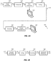
    • FIG. 1A depicts an example process for a video delivery pipeline;
    • FIG. 1B depicts an example process for data compression using content-adaptive quantization or reshaping according to an embodiment of this invention;
    • FIG. 2 depicts an example process for block-based, content-adaptive reshaping according to an embodiment of this invention;
    • FIG. 3 depicts an example of a mapping function which maps average standard deviation values to required signal bit depth according to an embodiment of this invention;
    • FIG. 4 depicts examples of computed normalized codeword allocations according to embodiments of this invention; and
    • FIG. 5 depicts an example of a forward reshaping function computed according to an embodiment of this invention.
    DESCRIPTION OF EXAMPLE EMBODIMENTS
  • Block-based, content-adaptive techniques for image reshaping of high dynamic range (HDR) images are described herein. In the following description, for the purposes of explanation, numerous specific details are set forth in order to provide a thorough understanding of the present invention. It will be apparent, however, that the present invention may be practiced without these specific details. In other instances, well-known structures and devices are not described in exhaustive detail, in order to avoid unnecessarily occluding, obscuring, or obfuscating the present invention.
  • OVERVIEW
  • Example embodiments described herein relate to block-based image reshaping of HDR images. A processor for signal reshaping receives an input image with an input bit depth. The image is divided in to blocks and a metric of complexity of each block (such as, its standard deviation) is computed. The input codewords are divided into codeword bins and each bin is assigned a metric of complexity value. For each bin, a metric of complexity to bit-depth function is applied to the bin values to generate minimal bit depth values for each codeword bin. An output codeword mapping function is generated based on the input bit depth, a target bit depth, and the minimal bit depth values. The codeword mapping function is applied to the input image to generate an output image in the target bit depth.
  • In an embodiment, the measure of complexity comprises computing the standard deviation of image blocks.
  • EXAMPLE VIDEO DELIVERY PROCESSING PIPELINE
  • FIG. 1A depicts an example process of a conventional video delivery pipeline (100) showing various stages from video capture to video content display. A sequence of video frames (102) is captured or generated using image generation block (105). Video frames (102) may be digitally captured (e.g. by a digital camera) or generated by a computer (e.g. using computer animation) to provide video data (107). Alternatively, video frames (102) may be captured on film by a film camera. The film is converted to a digital format to provide video data (107). In a production phase (110), video data (107) is edited to provide a video production stream (112).
  • The video data of production stream (112) is then provided to a processor at block (115) for post-production editing. Block (115) post-production editing may include adjusting or modifying colors or brightness in particular areas of an image to enhance the image quality or achieve a particular appearance for the image in accordance with the video creator's creative intent. This is sometimes called "color timing" or "color grading." Other editing (e.g. scene selection and sequencing, image cropping, addition of computer-generated visual special effects, etc.) may be performed at block (115) to yield a final version (117) of the production for distribution. During post-production editing (115), video images are viewed on a reference display (125).
  • Following post-production (115), video data of final production (117) may be delivered to encoding block (120) for delivering downstream to decoding and playback devices such as television sets, set-top boxes, movie theaters, and the like. In some embodiments, coding block (120) may include audio and video encoders, such as those defined by ATSC, DVB, DVD, Blu-Ray, and other delivery formats, to generate coded bit stream (122). In a receiver, the coded bit stream (122) is decoded by decoding unit (130) to generate a decoded signal (132) representing an identical or close approximation of signal (117). The receiver may be attached to a target display (140) which may have completely different characteristics than the reference display (125). In that case, a display management block (135) may be used to map the dynamic range of decoded signal (132) to the characteristics of the target display (140) by generating display-mapped signal (137).
  • Signal Reshaping
  • Currently, most digital interfaces for video delivery, such as the Serial Digital Interface (SDI) are limited to 12 bits per pixel per component. Furthermore, most compression standards, such as H.264 (or AVC) and H.265 (or HEVC), are limited to 10-bits per pixel per component. Therefore efficient encoding and/or quantization is required to support HDR content, with dynamic range from approximately 0.001 to 10,000 cd/m2 (or nits), within existing infrastructures and compression standards.
  • The term "PQ" as used herein refers to perceptual luminance amplitude quantization. The human visual system responds to increasing light levels in a very non-linear way. A human's ability to see a stimulus is affected by the luminance of that stimulus, the size of the stimulus, the spatial frequencies making up the stimulus, and the luminance level that the eyes have adapted to at the particular moment one is viewing the stimulus. In a preferred embodiment, a perceptual quantizer function maps linear input gray levels to output gray levels that better match the contrast sensitivity thresholds in the human visual system. An example PQ mapping function is described in SMPTE ST 2084:2014 "High Dynamic Range EOTF of Mastering Reference Displays," which is incorporated herein by reference in its entirety, where given a fixed stimulus size, for every luminance level (i.e., the stimulus level), a minimum visible contrast step at that luminance level is selected according to the most sensitive adaptation level and the most sensitive spatial frequency (according to HVS models). Compared to the traditional gamma curve, which represents the response curve of a physical cathode ray tube (CRT) device and coincidently may have a very rough similarity to the way the human visual system responds, a PQ curve imitates the true visual response of the human visual system using a relatively simple functional model.
  • For example, under SMPTE ST 2084, at 1 cd/m2, one 12-bit code value corresponds to a relative change of approximately 0.0048 cd/m2; however, at 1,000 cd/m2, one 12-bit code value corresponds to a relative change of approximately 2.24 cd/m2. This non-linear quantization is needed to accommodate for the non-linear contrast sensitivity of the human visual system (HVS).
  • Another example of a perceptually-quantized EOTF is presented in "Chromaticity based color signals for wide color gamut and high dynamic range," by J. Stessen et al., ISO/IEC JTC1/SC29/WG11 MPEG2014/M35065, Oct. 2014, which is incorporated herein by reference in its entirety.
  • Contrast sensitivity of the HVS does not only depend on luminance but also on masking characteristics of the image content (most particularly noise and texture), as well as the adaptation state of the HVS. In other words, depending on the noise level or the texture characteristics of an image, image content can be quantized with larger quantization steps than those predicted by PQ or gamma quantizers, because texture and noise mask quantization artifacts. The PQ quantization describes the best the HVS can do, which occurs when there is no noise or masking in the image. However, for many images (frames of a video), there is significant masking.
  • In addition to noise and texture masking, other characteristics of visual behavior, such as optical flare and local adaptation may also be taken into consideration to increase the level of quantization and allow representing HDR images at 10-bits or lower per color component. As used herein, the terms "Content-Adaptive PQ" or "Content-adaptive reshaping" denote methods to adaptively adjust the perceptually quantization of images based on their content.
  • FIG. 1B depicts an example process for content-adaptive reshaping according to an embodiment. Given input frames (117), a forward reshaping block (150) analyzes the input and the coding constrains and generates codeword mapping functions which map input frames (117) to re-quantized output frames (152). For example, input (117) may be gamma-coded or PQ-coded according to certain EOTF. In some embodiments, information about the reshaping process may be communicated to downstream devices (such as decoders) using metadata. Following coding (120) and decoding (130), decoded frames (132) may be processed by a backward reshaping function (160), which converts the re-quantized frames (132) back to the original EOTF domain (e.g., gamma or PQ), for further downstream processing, such as the display management process (135) discussed earlier. In some embodiments, the backward or inverse reshaping function (160) may be integrated with a de-quantizer in decoder (130), e.g., as part of the de-quantizer in an AVC or HEVC video decoder.
  • An example of a signal reshaping function was presented in U.S. Provisional Patent Application Ser. No. 62/126,925, filed on March 2, 2015, "Content-adaptive perceptual quantizer for high dynamic range images," by J. Froehlich et al. , which is incorporated herein by reference in its entirety, to be referred to as the '925 Application, or the CAQ method. According to the CAQ method, the reshaping function is computed according to a noise mask histogram of the input image. Alternative, block-based reshaping techniques are described next.
  • Block-based Reshaping
  • FIG. 2 depicts an example process for block-based content-adaptive reshaping according to an embodiment of this invention. As depicted in FIG. 2, given a sequence of images (e.g., video frames) (117), in block (205), each image is divided into non overlapping blocks and the standard deviation (σ) for pixel values in each block is computed. In step (210), input codewords are divided into bins and the average standard deviation for each bin is computed. Block (215) computes the number of minimum bits required for each bin. Based on this information, in block (220), output codewords are assigned to each bin. Finally, in (225), a forward reshaping function is constructed based on the output codeword assignment. Each of these steps is described in more detail next.
  • In an embodiment, without limitation, let Ij (p) denote the p-th pixel of a color component under quantization (e.g., luminance) in the j-th frame in the input sequence (117), normalized to [0 1). Let vLj and vHj denote the minimum and maximum pixel values in this frame, or v L j = min I j p , v H j = max I j p .
    Figure imgb0001
  • Frame Ij is divided into rectangular, non-overlapping blocks (e.g., into n x n blocks, where n = 16). Denote the set of pixels within the k-th block as θj,k = {p|pblock(k)}. Then, the mean and standard deviation of the pixel values within the k-th, n x n, block may be computed as: mean j , k = p θ j , k I j p n 2 ,
    Figure imgb0002
    and σ j , k = std j , k = p θ j , k I j p 2 n 2 mean j , k 2 .
    Figure imgb0003
  • In an embodiment, all pixels in the k-th block of the j-th frame are associated with the same standard deviation, stdj , k . Let Hj (p) denote the standard deviation of all pixels in the j-th frame. In an embodiment, in the process of designing a reshaping function for frame j some pixels in Hj (p) may be excluded. These pixels may include:
    • Pixels of a letterbox area within the input image (that is, dark areas added to a picture so its size matches a certain aspect ratio). Pixels in letterbox areas have constant values, hence zero standard deviation.
    • Pixels at the right- and bottom-ends of the frame. If the size of the picture does not accommodate an integer number of the n x n blocks, then pixel areas at the right- and bottom-ends of the frame, where their corresponding blocks have a smaller size, may be excluded.
  • Let Ωj denote the set of valid (not excluded) pixel indices for the j-th frame. Let i be an index inside Ωj. Then, H j i , i Ω j
    Figure imgb0004
    denotes the set of valid standard deviations for all pixels in the j-th frame. Experimental results indicate that standard deviation maps provide a good, and simple to compute, representation of the underlying frequency content in each frame and thus can be used to decide how to allocate different bit depths to different regions in each frame. However, the methods described herein are equally applicable using alternative metrics of the complexity of an image block, such as their variance, their entropy, frequency response, and the like.
  • Let BI denote the bit-depth of the input image (117) (e.g., BI = 16) and let K = 2 BI , then the dynamic range 0 to K-1 may be partitioned into M bins of equal number (W) of input codewords, that is W = K/M. Let bj,m. denote the average standard deviation of all valid pixels with input values belonging to the m-th bin, where m = 0, 1, ..., M-1. That is, for Ij (i),i∈Ω j ,
    if Ψ j , m = i | m M I j i < m + 1 M ,
    Figure imgb0005
    then b j , m = mean H j i | i Ψ j , m .
    Figure imgb0006
    Note that for specific images there might exist some codeword bins with no pixels inside them. These bins may be marked so that they can be properly accounted for and/or adjusted in the next step.
  • Signal reshaping functions may be generated at the frame level or at the scene level. As used herein, the terms 'scene' or 'shot' for a video sequence may relate to a series of consecutive frames in the video signal sharing similar color and dynamic range characteristics. Because of the consecutive nature of video prediction in most video compression formats, it may be preferable to adjust the quantization parameters only at boundaries that match the typical boundaries of a video encoder, such as scene changes or a new group of pictures (GOP). Thus, given a scene with F frames and frame-based bj,m values, a scene-based measure of the standard deviation in each bin may be derived as b m = mean b j , m | j = 0 , 1 , , F 1 .
    Figure imgb0007
    For bins with no valid pixel values within a whole scene, in an embodiment, their standard deviation is set to a large number (say, 1 or higher) to guarantee that that no codewords are assigned to them. In another embodiment, let vL and vH denote the minimum and maximum pixel values within a scene, that is: v L = min v Lj , v H = max v Hj ,
    Figure imgb0008
    then for empty bins, the following process may be employed:
    • If the luminance values in a bin are lower than vL , then assign to this bin the same average standard deviation value as the closest bin to the right
    • Else, if the luminance values in a bin are higher than vH , then assign to this bin the same average standard deviation value as the closest bin to the left
    • Else, interpolate the bin value from its neighbor bins
    Minimum bit-depth per bin
  • Given the computed bm levels for a scene, the next step would be to determine the number of bits that need to be allocated for each bin. In an embodiment, such a mapping may be determined based on experimental user study results. For example, in one such study, users were shown to evaluate test images constructed as follows:
    1. a) A selection of 16-bit HDR frames was converted from the original RGB space to the color space to be used during the compression step (120)
    2. b) The color-transformed images were truncated (starting from the least significant bit (LSB)) to bit depths ranging from 7 bits to 11 bits
    3. c) The LSB-truncated images were converted back to the RGB color space
    4. d) Then, for each image, the minimum required bit-depth for which the output image does not exhibit any artifacts, such as false contouring, was determined
  • FIG. 3 depicts an example of such results for a set of video data coded according to ST 2084. In FIG. 3, curve (305) represents the worst case results for the tested images, thus representing the worst-case bit-depth requirements as a function of computed average standard deviation. From FIG. 3, for example, for an average standard deviation of 2-8, the required bit depth is about 9.75 bits. As expected, FIG. 3 indicates that image regions with higher levels of complexity can be coded at smaller bit depths. Alternatively, the smoother the image, the more bit depth is needed for an accurate and perceptually lossless representation.
  • Given a set of average standard deviation values, stdi, i = 0, 1, 2, ..., N-1, where stdi std i+1, let i denote the corresponding computed minimum bit depth. Based on these samples, one may derive a standard deviation to bit-depth allocation function fB (), so that Q m = f B b m ,
    Figure imgb0009
  • In an embodiment, fB () can be a piece-wise linear function computed using linear interpolation. For example, for std n b m std n + 1 Q m = Q ˜ n Q ˜ n Q ˜ n + 1 b m std n std n + 1 std n .
    Figure imgb0010
  • However, other interpolation techniques known in the art, such as bilinear interpolation, spline interpolation, and the like, could also be used.
  • In an embodiment, it may be more convenient to perform codeword mapping (220) based on the number of required codewords within each bin instead of using the bit depth data directly. This is examined in the next section.
  • Codeword Mapping Generation
  • Let BT denote the target bit-depth for the re-quantized signal (152) (e.g., BT = 10 bits/pixel per color component), then the output will be mapped using 2 BT codewords. In an embodiment, the range of codewords is normalized to be in [0, 1), hence let D m = 2 Q m 2 B T / 2 B I .
    Figure imgb0011
    denote the number of required normalized codewords per bin m. For example, if Qm = 9, BI = 16 and BT = 10, then Dm = 2-17.
  • Let d i = D m for m 1 W i < mW ,
    Figure imgb0012
    denote the number of normalized codewords per input i ∈ (0, 2 BI - 1), then di can be considered a lower bound for the number of required codewords per input codeword. The total number of normalized codewords for all output codewords, D, is bounded by 1, or D = i = v L v H d i 1.
    Figure imgb0013
  • Let U = 1- D denote the number of unused normalized codewords after applying equation (12). These unused codewords need to be reassigned to output codewords according to a given criterion. In an embodiment, using a constant allocation scheme, for input vL ivH, the same amount of additional codewords are assigned based on the existing distribution, or d ˜ i = d i + U v H v L ,
    Figure imgb0014
    where i denotes the updated number of normalized codeword values. Additional reallocation techniques were also presented in the '925 Application. In this invention, another codeword allocation scheme based on computed entropy is also proposed as follows.
  • Consider a region Ω i surrounding the i-th pixel in the j-th frame (e.g., a 5 x 5 area with the i-th pixel in the center), then the entropy of the i-th pixel may be computed as E j i = k Ω i p k log p k ,
    Figure imgb0015
    where p(k) denotes an empirical probability for the occurrence of pixel value k. For example: p k = y = k | y Ω i Ω i ,
    Figure imgb0016
    where |X| denotes the number of elements in set X.
  • Without loss of generality, in an embodiment, let E j NL i = E j i 1 / 2
    Figure imgb0017
    represent a non-linear mapping of the entropy values so that more codewords are allocating to regions of higher complexity while smoother areas, with low entropy, are also guaranteed not to get too few codewords, thus preventing coding artifacts. After normalizing with the maximum entropy value within each frame, the final entropy of the j-th frame is given by E j NL i = E j NL i / max i E J NL I .
    Figure imgb0018
  • Let Ej,m denote the mean entropy within each codeword bin m in the j-th frame, and let Em = mean(Ej,m |j = 0,1, ... , F - 1) denote the average entropy in each codeword bin within a scene, then, in an embodiment, for vL ivH, unused codewords are allocated based on d ˜ i = d i + a U v H v L + 1 a e i S e ,
    Figure imgb0019
    where a is a constant between 0 and 1 (e.g., a = 0.1) that determines what proportion of the unused codewords is assigned using a constant allocation scheme, e.g., as in equation (14), and what proportion takes into consideration the computed entropy values, e i = E m for m 1 W i < mW ,
    Figure imgb0020
    and S e = i e i for v L i v H .
    Figure imgb0021
  • In another embodiment, let u i = U i v L v H v L α , for v L i v H ,
    Figure imgb0022
    where α is a constant (e.g. α = 1.4), . Then, unused codewords are allocated based on d ˜ i = d 1 + u i u i 1 , for v L + 1 i v H .
    Figure imgb0023
    Experimental results have indicated that this allocation scheme tends to preserve better film grain, camera noise, or details at certain high bit rates.
  • In an embodiment, the allocation curves may also be smoothed using a low-pass filter or a moving average filter to ensure the curve is smooth and the inverse reshaping function is easy to approximate using a piece-wise polynomial. For example, in an embodiment s ˜ i = k = W W a k d ˜ i + k ,
    Figure imgb0024
    where a k = 1 2 W + 1 .
    Figure imgb0025
  • In an embodiment, no codewords are assigned to values outside the (vL , vH ) range, or s ˜ i = 0 for i < v L and i > v H .
    Figure imgb0026
  • Furthermore, in case the sum of smoothed values exceeds 1, the codeword assignment needs to be normalized. For example, if S = i = v L v H s ˜ i > 1 ,
    Figure imgb0027
    then s i = s ˜ i S .
    Figure imgb0028
  • Given the final allocation of codewords in each codeword bin, a forward reshaping function may be generated as FL i = k = 0 i s k .
    Figure imgb0029
    Given FL(i), then, in the j-th frame, for a given input pixel Ij (p) = i(i ∈ (0, 2 BI -1)) the final, normalized, re-quantized pixel value sjp may be expressed as: s jp = { 0 , if i < v L 1 , if i > v H FL i , if v L i v H .
    Figure imgb0030
  • In an embodiment, FL(i) values may be stored in a pre-computed look-up table (LUT). Alternatively, normalized sjp values may also be mapped to de-normalized values in the range 0 to 2 BT - 1.
  • FIG. 4 depicts example plots for codeword allocation according to embodiments. Plot (610) shows the original allocation based on the computed lower bit-depth values (e.g., using equation (12)) for a scene, for BI = 16 (input codewords range from 0 to 65,535). FIG. 4 also shows the number of normalized codewords after the final allocation, using both smoothed (620) and unsmoothed (615) curves. FIG. 5, depicts an example look-up table for reshaping 16-bit input data into 10-bit output data according to embodiments of this invention.
  • People skilled in the art will appreciate that while the methods discussed herein are based on a block-based measure of standard deviation, other measures of block complexity, such as their variance, entropy (for example, as computed in equation (15)), frequency transform components, and the like, may also be applied.
  • Backward or Inverse Reshaping
  • In some embodiments, backward reshaping (160) may be applied to reverse the effects of forward reshaping (150). In an embodiment, a look-up table for inverse quantization may be constructed as follows:
    1. a) For each codeword in the quantized domain (sc ), identify all input codewords (vi ) for which FL(vi ) = sc. Let this group be denoted as ω(sc ) = {vi |FL(vi )=sc }; then
    2. b) Construct the backward reshaping function (BL(sc )) as a function of ω(sc ).
  • For example, in an embodiment, without limitation, BL(sc ) may be constructed as the average of all codewords that belong to ω(sc ), or
    if |ω(sc )| > 0,
    then BL s c = i ω s c v i ω s c ,
    Figure imgb0031
    where |ω(sc )| denotes the number of elements in the set ω(sc ). If |ω(sc )|=0 for any sc values, in an embodiment, these values may be interpolated from its neighbor non-zero values. In another embodiment, backward reshaping may be defined as min(ω(sc )).
  • EXAMPLE COMPUTER SYSTEM IMPLEMENTATION
  • Embodiments of the present invention may be implemented with a computer system, systems configured in electronic circuitry and components, an integrated circuit (IC) device such as a microcontroller, a field programmable gate array (FPGA), or another configurable or programmable logic device (PLD), a discrete time or digital signal processor (DSP), an application specific IC (ASIC), and/or apparatus that includes one or more of such systems, devices or components. The computer and/or IC may perform, control, or execute instructions relating to the block-based reshaping of images with enhanced dynamic range, such as those described herein. The computer and/or IC may compute any of a variety of parameters or values that relate to the block-based reshaping processes described herein. The image and video embodiments may be implemented in hardware, software, firmware and various combinations thereof.
  • Certain implementations of the invention comprise computer processors which execute software instructions which cause the processors to perform a method of the invention. For example, one or more processors in a display, an encoder, a set top box, a transcoder or the like may implement methods related to block-based reshaping of HDR images as described above by executing software instructions in a program memory accessible to the processors. The invention may also be provided in the form of a program product. The program product may comprise any non-transitory medium which carries a set of computer-readable signals comprising instructions which, when executed by a data processor, cause the data processor to execute a method of the invention. Program products according to the invention may be in any of a wide variety of forms. The program product may comprise, for example, physical media such as magnetic data storage media including floppy diskettes, hard disk drives, optical data storage media including CD ROMs, DVDs, electronic data storage media including ROMs, flash RAM, or the like. The computer-readable signals on the program product may optionally be compressed or encrypted.
  • Where a component (e.g. a software module, processor, assembly, device, circuit, etc.) is referred to above, unless otherwise indicated, reference to that component (including a reference to a "means") should be interpreted as including as equivalents of that component any component which performs the function of the described component (e.g., that is functionally equivalent), including components which are not structurally equivalent to the disclosed structure which performs the function in the illustrated example embodiments of the invention.
  • EQUIVALENTS, EXTENSIONS, ALTERNATIVES AND MISCELLANEOUS
  • Example embodiments that relate to the efficient block-based reshaping of HDR images are thus described. In the foregoing specification, embodiments of the present invention have been described with reference to numerous specific details that may vary from implementation to implementation. Thus, the sole and exclusive indicator of what is the invention, and is intended by the applicants to be the invention, is the set of claims that issue from this application, in the specific form in which such claims issue, including any subsequent correction. Any definitions expressly set forth herein for terms contained in such claims shall govern the meaning of such terms as used in the claims. Hence, no limitation, element, property, feature, advantage or attribute that is not expressly recited in a claim should limit the scope of such claim in any way. The specification and drawings are, accordingly, to be regarded in an illustrative rather than a restrictive sense.
  • Various aspects of the present invention may be appreciated from the following enumerated example embodiments (EEEs):
    • EEE 1. A method for adaptive image reshaping with a processor, the method comprising:
      • accessing with a processor an input image in an input bit depth;
      • dividing the input image into a plurality of blocks and computing for one or more image blocks a measure of complexity of their pixel values;
      • dividing a range of input codewords into a plurality of codeword bins;
      • for one or more of the codeword bins:
        • computing a bin measure of complexity value based on the block measures of complexity of at least the input image;
        • applying a measure of complexity to bit-depth function to generate a minimal bit-depth value;
      • generating a codeword mapping function based on the input bit depth, the minimal bit depth values, and a target bit depth, wherein the codeword mapping function maps input codewords in the input bit depth to output codewords in the target bit depth; and
      • applying the codeword mapping function to the input image to generate an output image in the target bit depth.
    • EEE 2. The method of EEE 1, wherein computing the measure of complexity of pixel values in a block comprises computing the standard deviation of the pixel values in the block.
    • EEE 3. The method of EEE 1 or EEE 2, further comprising:
      • applying a pixel selection process to the input image to eliminate computing block measures of complexity for pixels deemed not essential in image reshaping.
    • EEE 4. The method of any of the EEEs 1-3, wherein the input image is a high dynamic range image encoded according to gamma encoding or SMPTE ST 2084.
    • EEE 5. The method of any of the EEEs 1-4, wherein the measure of complexity to bit-depth function is generated according to results from a perceptual user study.
    • EEE 6. The method of EEE 5, wherein the perceptual user study comprises:
      • accessing a plurality of original high dynamic range (HDR) images in the input bit depth;
      • for each original image in the plurality of high dynamic range images:
        • converting the original image from its original color space to a second color space;
        • truncating the image in the second color space to generate truncated images at bit depths lower than the input bit depth;
        • converting the truncated images to the original color space to generate reconstructed images; and
        • determining the lower bit-depth for which one of the truncated images in the original color space best matches the original image.
    • EEE 7. The method of any of the EEEs 1-6, wherein generating the codeword mapping function further comprises:
      • for each codeword bin:
        • generating a lower bound of normalized number of required codewords in the target bit depth based on the minimal bit depth values, the input bit depth and the target bit depth;
      • allocating unused normalized codewords to each bin image according to an allocation scheme to generate updated normalized numbers of required codewords; and
      • generating the codeword mapping function by computing a cumulative sum of the updated normalized numbers of required codewords.
    • EEE 8. The method of EEE 7, further comprising, filtering the updated normalized numbers of required codewords by a low-pass filter before generating the codeword mapping function.
    • EEE 9. The method of EEE 7 or EEE 8, wherein the allocation scheme comprises a constant offset allocation scheme, where for the i-th input pixel value d ˜ i = d i + U v H v L ,
      Figure imgb0032
      wherein i denotes the updated normalized number of codeword values, di denotes the normalized number of required codewords, if D denotes the sum of di values, then U=1-D, vH denotes a maximum input pixel value, and vL denotes a minimum input pixel value.
    • EEE 10. The method of EEE 7 or EEE 8, wherein the allocation scheme comprises computing d ˜ i = d i + u i u i 1 , for v L + 1 i v H .
      Figure imgb0033
      wherein i denotes the updated normalized number of codeword values, di denotes the normalized number of required codewords, if D denotes the sum of di values, then U=1-D, vH denotes a maximum input pixel value, vL denotes a minimum input pixel value, and u i = U i v L v H v L α , for v L i v H ,
      Figure imgb0034
      where α is a constant.
    • EEE 11. The method of EEE 7 or EEE 8, wherein the allocation scheme comprises an entropy-based allocation scheme, where for the i-th input pixel value d ˜ i = d i + a U v H v L + 1 a e i S e ,
      Figure imgb0035
      wherein i denotes the updated normalized number of codeword values, di denotes the normalized number of required codewords, if D denotes the sum of di values, then U=1-D, a is a scalar between 0 and 1, vH denotes a maximum input pixel value and vL denotes a minimum input pixel value, ei denotes a measure of local entropy for the i-th codeword, and S e = i e i for v L i v H .
      Figure imgb0036
    • EEE 12. The method of any of the EEEs 7-11, wherein generating the codeword mapping function for an input pixel value i comprises computing FL i = k = 0 i s k ,
      Figure imgb0037
      wherein sk values are derived based on the updated normalized number of codeword values.
    • EEE 13. The method of EEE 12, wherein generating the output image comprises computing: s p = { 0 , if i < v L 1 , if i > v H FL i , if v L i > v H ,
      Figure imgb0038
      wherein for a pixel Ip = i in the input image, sp denotes the corresponding, normalized, quantized output pixel, vH denotes a maximum input pixel value, and vL denotes a minimum input pixel value.
    • EEE 14. The method of any of the EEEs 1-13, wherein the bin measures of complexity values are computed based on block complexity values computed across multiple consecutive frames in a video scene that includes the input image.
    • EEE 15. An apparatus comprising a processor and configured to perform the method recited in any of the EEEs 1-14.
    • EEE 16. A non-transitory computer-readable storage medium having stored thereon computer-executable instruction for executing a method in accordance with any of the EEEs 1-14.

Claims (15)

  1. A method for adaptive image reshaping with a processor, the method comprising:
    accessing with a processor an input image in an input bit depth;
    dividing the input image into a plurality of blocks and computing for one or more image blocks a measure of complexity of their pixel values;
    dividing a range of input codewords into a plurality of codeword bins;
    for one or more of the codeword bins:
    computing a bin measure of complexity value based on the block measures of complexity of at least the input image;
    applying a measure of complexity to bit-depth function to generate a minimal bit-depth value;
    generating a codeword mapping function based on the input bit depth, the minimal bit depth values, and a target bit depth, wherein the codeword mapping function maps input codewords in the input bit depth to output codewords in the target bit depth; and
    applying the codeword mapping function to the input image to generate an output image in the target bit depth.
  2. The method of claim 1, wherein computing the measure of complexity of pixel values in a block comprises computing the standard deviation of the pixel values in the block.
  3. The method of claim 1 or 2, further comprising:
    applying a pixel selection process to the input image to eliminate computing block measures of complexity for pixels deemed not essential in image reshaping.
  4. The method of any of the claims 1-3, wherein the input image is a high dynamic range image encoded according to gamma encoding or SMPTE ST 2084.
  5. The method of any of the claims 1-4, wherein the measure of complexity to bit-depth function is generated according to results from a perceptual user study.
  6. The method of claim 5, wherein the perceptual user study comprises:
    accessing a plurality of original high dynamic range (HDR) images in the input bit depth;
    for each original image in the plurality of high dynamic range images:
    converting the original image from its original color space to a second color space;
    truncating the image in the second color space to generate truncated images at bit depths lower than the input bit depth;
    converting the truncated images to the original color space to generate reconstructed images; and
    determining the lower bit-depth for which one of the truncated images in the original color space best matches the original image.
  7. The method of any of the claims 1-6, wherein generating the codeword mapping function further comprises:
    for each codeword bin:
    generating a lower bound of normalized number of required codewords in the target bit depth based on the minimal bit depth values, the input bit depth and the target bit depth;
    allocating unused normalized codewords to each bin image according to an allocation scheme to generate updated normalized numbers of required codewords; and
    generating the codeword mapping function by computing a cumulative sum of the updated normalized numbers of required codewords.
  8. The method of claim 7, further comprising, filtering the updated normalized numbers of required codewords by a low-pass filter before generating the codeword mapping function.
  9. The method of claim 7 or 8, wherein the allocation scheme comprises a constant offset allocation scheme, where for the i-th input pixel value d ˜ i = d i + U v H v L ,
    Figure imgb0039
    wherein i denotes the updated normalized number of codeword values, di denotes the normalized number of required codewords, if D denotes the sum of di values, then U=1-D, vH denotes a maximum input pixel value, and vL denotes a minimum input pixel value.
  10. The method of claim 7 or claim 8, wherein the allocation scheme comprises computing d ˜ i = d i + u i u i 1 , for v L + 1 i v H .
    Figure imgb0040
    wherein i denotes the updated normalized number of codeword values, di denotes the normalized number of required codewords, if D denotes the sum of di values, then U=1-D, vH denotes a maximum input pixel value, vL denotes a minimum input pixel value, and u i = U i v L v H v L α , for v L i v H ,
    Figure imgb0041
    where α is a constant.
  11. The method of claim 7 or claim 8, wherein the allocation scheme comprises an entropy-based allocation scheme, where for the i-th input pixel value d ˜ i = d i + a U v H v L + 1 a e i S e ,
    Figure imgb0042
    wherein i denotes the updated normalized number of codeword values, di denotes the normalized number of required codewords, if D denotes the sum of di values, then U=1-D, a is a scalar between 0 and 1, vH denotes a maximum input pixel value and vL denotes a minimum input pixel value, ei denotes a measure of local entropy for the i-th codeword, and Se = ∑ iei for vL ivH.
  12. The method of any of the claims 7-11, wherein generating the codeword mapping function for an input pixel value i comprises computing FL i = k = 0 i s k ,
    Figure imgb0043
    wherein sk values are derived based on the updated normalized number of codeword values.
  13. The method of claim 12, wherein generating the output image comprises computing: s p = { 0 , if i > v L 1 , if i > v H FL i , if v L i v H ,
    Figure imgb0044
    wherein for a pixel Ip = i in the input image, sp denotes the corresponding, normalized, quantized output pixel, vH denotes a maximum input pixel value, and vL denotes a minimum input pixel value.
  14. The method of any of the claims 1-13, wherein the bin measures of complexity values are computed based on block complexity values computed across multiple consecutive frames in a video scene that includes the input image.
  15. An apparatus comprising a processor and configured to perform the method recited in any of the claims 1-14.
EP17154335.8A 2016-02-02 2017-02-02 Block-based content-adaptive reshaping for high dynamic range images Pending EP3203442A1 (en)

Applications Claiming Priority (2)

Application Number Priority Date Filing Date Title
US201662290399P 2016-02-02 2016-02-02
US201662334099P 2016-05-10 2016-05-10

Publications (1)

Publication Number Publication Date
EP3203442A1 true EP3203442A1 (en) 2017-08-09

Family

ID=57965737

Family Applications (1)

Application Number Title Priority Date Filing Date
EP17154335.8A Pending EP3203442A1 (en) 2016-02-02 2017-02-02 Block-based content-adaptive reshaping for high dynamic range images

Country Status (2)

Country Link
US (1) US10032262B2 (en)
EP (1) EP3203442A1 (en)

Cited By (2)

* Cited by examiner, † Cited by third party
Publication number Priority date Publication date Assignee Title
CN109345525A (en) * 2018-09-27 2019-02-15 方玉明 One kind removing ghost high dynamic range images quality evaluating method
WO2023069585A1 (en) 2021-10-21 2023-04-27 Dolby Laboratories Licensing Corporation Context-based reshaping algorithms for encoding video data

Families Citing this family (19)

* Cited by examiner, † Cited by third party
Publication number Priority date Publication date Assignee Title
US10032262B2 (en) * 2016-02-02 2018-07-24 Dolby Laboratories Licensing Corporation Block-based content-adaptive reshaping for high dynamic range images
WO2018044803A1 (en) 2016-08-30 2018-03-08 Dolby Laboratories Licensing Corporation Real-time reshaping of single-layer backwards-compatible codec
ES2967322T3 (en) 2016-08-30 2024-04-29 Dolby Laboratories Licensing Corp Backwards-compatible single-layer codec real-time remodeling
EP3510772B1 (en) 2016-09-09 2020-12-09 Dolby Laboratories Licensing Corporation Coding of high dynamic range video using segment-based reshaping
WO2018049335A1 (en) 2016-09-09 2018-03-15 Dolby Laboratories Licensing Corporation Coding of high dynamic range video using segment-based reshaping
US10609372B2 (en) 2017-09-29 2020-03-31 Dolby Laboratories Licensing Corporation Up-conversion to content adaptive perceptual quantization video signals
CN117082246A (en) * 2018-02-14 2023-11-17 杜比实验室特许公司 Image reshaping with rate-distortion optimization in video coding
JP6964807B2 (en) 2018-05-11 2021-11-10 ドルビー ラボラトリーズ ライセンシング コーポレイション High fidelity full-reference and reduced-reference coding in an end-to-end single-layer backward-compatible coding pipeline
CN112585969B (en) 2018-08-10 2023-03-28 杜比实验室特许公司 Method, apparatus and storage medium for reducing banding artifacts in target images
EP3857505B1 (en) 2018-09-24 2022-08-03 Dolby Laboratories Licensing Corporation Image denoising in sdr to hdr image conversion
US11277646B2 (en) 2018-10-03 2022-03-15 Dolby Laboratories Licensing Corporation Reducing banding artifacts in backward-compatible HDR imaging
US11388408B2 (en) 2018-12-03 2022-07-12 Dolby Laboratories Licensing Corporation Interpolation of reshaping functions
WO2021076822A1 (en) 2019-10-17 2021-04-22 Dolby Laboratories Licensing Corporation Adjustable trade-off between quality and computation complexity in video codecs
CN114747224B (en) 2019-11-27 2023-12-01 杜比实验室特许公司 Method, device and storage medium for generating shaping function
US20230156343A1 (en) 2020-04-03 2023-05-18 Dolby Laboratories Licensing Corporation Blind local reshaping in hdr imaging
CN115699734A (en) 2020-04-21 2023-02-03 杜比实验室特许公司 HDR imaging shaping function with continuity constraint and reversibility constraint
WO2022245695A1 (en) 2021-05-21 2022-11-24 Dolby Laboratories Licensing Corporation Patch-based reshaping and metadata for volumetric video
WO2022256205A1 (en) 2021-06-01 2022-12-08 Dolby Laboratories Licensing Corporation Rotation-enabled high dynamic range video encoding
WO2023215108A1 (en) 2022-05-05 2023-11-09 Dolby Laboratories Licensing Corporation Stereoscopic high dynamic range video

Citations (3)

* Cited by examiner, † Cited by third party
Publication number Priority date Publication date Assignee Title
WO2009127231A1 (en) * 2008-04-16 2009-10-22 Fraunhofer-Gesellschaft zur Förderung der angewandten Forschung e.V. Bit-depth scalability
WO2014204865A1 (en) * 2013-06-17 2014-12-24 Dolby Laboratories Licensing Corporation Adaptive reshaping for layered coding of enhanced dynamic range signals
WO2015130541A1 (en) * 2014-02-26 2015-09-03 Dolby Laboratories Licensing Corporation Luminance based coding tools for video compression

Family Cites Families (8)

* Cited by examiner, † Cited by third party
Publication number Priority date Publication date Assignee Title
US8019150B2 (en) * 2007-10-11 2011-09-13 Kwe International, Inc. Color quantization based on desired upper bound for relative quantization step
TWI479898B (en) * 2010-08-25 2015-04-01 Dolby Lab Licensing Corp Extending image dynamic range
TWI575933B (en) * 2011-11-04 2017-03-21 杜比實驗室特許公司 Layer decomposition in hierarchical vdr coding
EP2834980B1 (en) * 2012-04-05 2017-05-10 Telefonaktiebolaget LM Ericsson (publ) Sample adaptive filtering with offsets
US10419762B2 (en) * 2015-03-02 2019-09-17 Dolby Laboratories Licensing Corporation Content-adaptive perceptual quantizer for high dynamic range images
US10311558B2 (en) * 2015-11-16 2019-06-04 Dolby Laboratories Licensing Corporation Efficient image processing on content-adaptive PQ signal domain
US10223774B2 (en) * 2016-02-02 2019-03-05 Dolby Laboratories Licensing Corporation Single-pass and multi-pass-based polynomial approximations for reshaping functions
US10032262B2 (en) * 2016-02-02 2018-07-24 Dolby Laboratories Licensing Corporation Block-based content-adaptive reshaping for high dynamic range images

Patent Citations (3)

* Cited by examiner, † Cited by third party
Publication number Priority date Publication date Assignee Title
WO2009127231A1 (en) * 2008-04-16 2009-10-22 Fraunhofer-Gesellschaft zur Förderung der angewandten Forschung e.V. Bit-depth scalability
WO2014204865A1 (en) * 2013-06-17 2014-12-24 Dolby Laboratories Licensing Corporation Adaptive reshaping for layered coding of enhanced dynamic range signals
WO2015130541A1 (en) * 2014-02-26 2015-09-03 Dolby Laboratories Licensing Corporation Luminance based coding tools for video compression

Non-Patent Citations (3)

* Cited by examiner, † Cited by third party
Title
J. STESSEN ET AL.: "Chromaticity based color signals for wide color gamut and high dynamic range", ISO/IEC JTC1/SC29/WG11 MPEG2014/M35065, October 2014 (2014-10-01)
NATALE DONALD J ET AL: "High dynamic range (HDR) video processing for the exploitation of high bit-depth sensors in human-monitored surveillance", 2014 IEEE APPLIED IMAGERY PATTERN RECOGNITION WORKSHOP (AIPR), IEEE, 14 October 2014 (2014-10-14), pages 1 - 6, XP032736157, DOI: 10.1109/AIPR.2014.7041912 *
PU F ET AL: "Comments on Reshaping for HDR/WCG compression", 113. MPEG MEETING; 19-10-2015 - 23-10-2015; GENEVA; (MOTION PICTURE EXPERT GROUP OR ISO/IEC JTC1/SC29/WG11),, no. m37267, 21 October 2015 (2015-10-21), XP030065635 *

Cited By (3)

* Cited by examiner, † Cited by third party
Publication number Priority date Publication date Assignee Title
CN109345525A (en) * 2018-09-27 2019-02-15 方玉明 One kind removing ghost high dynamic range images quality evaluating method
CN109345525B (en) * 2018-09-27 2022-03-29 方玉明 Ghost-removed high-dynamic-range image quality evaluation method
WO2023069585A1 (en) 2021-10-21 2023-04-27 Dolby Laboratories Licensing Corporation Context-based reshaping algorithms for encoding video data

Also Published As

Publication number Publication date
US20170221189A1 (en) 2017-08-03
US10032262B2 (en) 2018-07-24

Similar Documents

Publication Publication Date Title
US10032262B2 (en) Block-based content-adaptive reshaping for high dynamic range images
US10419762B2 (en) Content-adaptive perceptual quantizer for high dynamic range images
EP3281409B1 (en) In-loop block-based image reshaping in high dynamic range video coding
US10223774B2 (en) Single-pass and multi-pass-based polynomial approximations for reshaping functions
US10645403B2 (en) Chroma reshaping for high dynamic range images
US9230338B2 (en) Graphics blending for high dynamic range video
US20190349607A1 (en) Coding of high dynamic range video using segment-based reshaping
WO2017201139A1 (en) Chroma reshaping for high dynamic range images
EP3734588A1 (en) Color appearance preservation in video codecs
US10484684B2 (en) Signal reshaping and coding in the IPT-PQ color space
US10165275B2 (en) Content-adaptive reshaping for high dynamic range images
EP3371975B1 (en) Piecewise-linear inter-layer predictor for high-dynamic range video coding
WO2018049335A1 (en) Coding of high dynamic range video using segment-based reshaping
US20230039038A1 (en) Rate-control-aware reshaping in hdr imaging
US11895416B2 (en) Electro-optical transfer function conversion and signal legalization

Legal Events

Date Code Title Description
PUAI Public reference made under article 153(3) epc to a published international application that has entered the european phase

Free format text: ORIGINAL CODE: 0009012

STAA Information on the status of an ep patent application or granted ep patent

Free format text: STATUS: THE APPLICATION HAS BEEN PUBLISHED

AK Designated contracting states

Kind code of ref document: A1

Designated state(s): AL AT BE BG CH CY CZ DE DK EE ES FI FR GB GR HR HU IE IS IT LI LT LU LV MC MK MT NL NO PL PT RO RS SE SI SK SM TR

AX Request for extension of the european patent

Extension state: BA ME

STAA Information on the status of an ep patent application or granted ep patent

Free format text: STATUS: REQUEST FOR EXAMINATION WAS MADE

17P Request for examination filed

Effective date: 20180209

RBV Designated contracting states (corrected)

Designated state(s): AL AT BE BG CH CY CZ DE DK EE ES FI FR GB GR HR HU IE IS IT LI LT LU LV MC MK MT NL NO PL PT RO RS SE SI SK SM TR

STAA Information on the status of an ep patent application or granted ep patent

Free format text: STATUS: EXAMINATION IS IN PROGRESS

17Q First examination report despatched

Effective date: 20200304

STAA Information on the status of an ep patent application or granted ep patent

Free format text: STATUS: EXAMINATION IS IN PROGRESS

RAP3 Party data changed (applicant data changed or rights of an application transferred)

Owner name: DOLBY LABORATORIES LICENSING CORPORATION

P01 Opt-out of the competence of the unified patent court (upc) registered

Effective date: 20230417