EP3201066B1 - A member to control the direction of a vehicle, in particular a nautical vehicle - Google Patents
A member to control the direction of a vehicle, in particular a nautical vehicle Download PDFInfo
- Publication number
- EP3201066B1 EP3201066B1 EP15721836.3A EP15721836A EP3201066B1 EP 3201066 B1 EP3201066 B1 EP 3201066B1 EP 15721836 A EP15721836 A EP 15721836A EP 3201066 B1 EP3201066 B1 EP 3201066B1
- Authority
- EP
- European Patent Office
- Prior art keywords
- supporting
- vehicle
- skipper
- hub
- rotatable
- Prior art date
- Legal status (The legal status is an assumption and is not a legal conclusion. Google has not performed a legal analysis and makes no representation as to the accuracy of the status listed.)
- Active
Links
- 241000630329 Scomberesox saurus saurus Species 0.000 claims description 85
- 230000005540 biological transmission Effects 0.000 claims description 38
- 230000008878 coupling Effects 0.000 claims description 37
- 238000010168 coupling process Methods 0.000 claims description 37
- 238000005859 coupling reaction Methods 0.000 claims description 37
- 230000033001 locomotion Effects 0.000 claims description 19
- 238000003780 insertion Methods 0.000 claims description 4
- 230000037431 insertion Effects 0.000 claims description 4
- 239000004020 conductor Substances 0.000 description 2
- 230000008859 change Effects 0.000 description 1
- 239000000463 material Substances 0.000 description 1
- 230000004048 modification Effects 0.000 description 1
- 238000012986 modification Methods 0.000 description 1
- 230000002093 peripheral effect Effects 0.000 description 1
- 230000000007 visual effect Effects 0.000 description 1
Images


Classifications
-
- B—PERFORMING OPERATIONS; TRANSPORTING
- B63—SHIPS OR OTHER WATERBORNE VESSELS; RELATED EQUIPMENT
- B63H—MARINE PROPULSION OR STEERING
- B63H25/00—Steering; Slowing-down otherwise than by use of propulsive elements; Dynamic anchoring, i.e. positioning vessels by means of main or auxiliary propulsive elements
- B63H25/02—Initiating means for steering, for slowing down, otherwise than by use of propulsive elements, or for dynamic anchoring
-
- B—PERFORMING OPERATIONS; TRANSPORTING
- B62—LAND VEHICLES FOR TRAVELLING OTHERWISE THAN ON RAILS
- B62D—MOTOR VEHICLES; TRAILERS
- B62D1/00—Steering controls, i.e. means for initiating a change of direction of the vehicle
- B62D1/02—Steering controls, i.e. means for initiating a change of direction of the vehicle vehicle-mounted
- B62D1/04—Hand wheels
- B62D1/10—Hubs; Connecting hubs to steering columns, e.g. adjustable
- B62D1/105—Non-rotatable hubs, e.g. the central part of the steering wheel not rotating
-
- F—MECHANICAL ENGINEERING; LIGHTING; HEATING; WEAPONS; BLASTING
- F16—ENGINEERING ELEMENTS AND UNITS; GENERAL MEASURES FOR PRODUCING AND MAINTAINING EFFECTIVE FUNCTIONING OF MACHINES OR INSTALLATIONS; THERMAL INSULATION IN GENERAL
- F16H—GEARING
- F16H1/00—Toothed gearings for conveying rotary motion
- F16H1/02—Toothed gearings for conveying rotary motion without gears having orbital motion
- F16H1/04—Toothed gearings for conveying rotary motion without gears having orbital motion involving only two intermeshing members
- F16H1/06—Toothed gearings for conveying rotary motion without gears having orbital motion involving only two intermeshing members with parallel axes
- F16H1/10—Toothed gearings for conveying rotary motion without gears having orbital motion involving only two intermeshing members with parallel axes one of the members being internally toothed
-
- B—PERFORMING OPERATIONS; TRANSPORTING
- B63—SHIPS OR OTHER WATERBORNE VESSELS; RELATED EQUIPMENT
- B63H—MARINE PROPULSION OR STEERING
- B63H25/00—Steering; Slowing-down otherwise than by use of propulsive elements; Dynamic anchoring, i.e. positioning vessels by means of main or auxiliary propulsive elements
- B63H25/02—Initiating means for steering, for slowing down, otherwise than by use of propulsive elements, or for dynamic anchoring
- B63H2025/022—Steering wheels; Posts for steering wheels
Definitions
- This invention relates to a member to control the direction of a vehicle, preferably to control the direction of a nautical vehicle.
- prior art members preferably in the form of respective steering wheels to control the direction of a nautical vehicle, or boat, which comprise a respective rotatable body which can be manually operated by the skipper of the nautical vehicle to control the direction of the vehicle and is operatively connectable to means defining, or determining, the direction of travel of the vehicle.
- the rotatable bodies, or steering wheels, for controlling the direction of the nautical vehicle are operated for modifying the direction of travel of the vehicle in such a way as to perform ample rotations, that is to say, even in such a way as to perform several complete revolutions.
- a plurality of means, or components, which can be used by the skipper during the manoeuvre, for example elements, or pushbuttons, for controlling corresponding instruments, apparatuses and/or devices of the vehicle and/or of the control displays are positioned in a fixed manner on the dashboard of the nautical vehicle, and therefore in an inconvenient position to be viewed or to be reached and the skipper must therefore change his/her viewpoint and/or release the rotatable body to operate these, with a consequent high risk of performing incorrect manoeuvres.
- WO 2007/080357 A1 shows a steering wheel arrangement for a car in which the steering wheel has a central, non-rotating hub, around which an outer peripheral part of the steering wheel may be rotated.
- This invention therefore proposes a new solution as an alternative to the solutions known up to now and, more specifically, proposes to overcome one or more of the above mentioned drawbacks and/or problems and/or to meet one or more of the needs felt in the trade or inferable from the above.
- a hub according to independent claim 1 is therefore provided.
- the skipper By means of an hub according to independent claim 1, it is possible for the skipper to have easy access, also visual, to the means which can be used, in particular which can be operated and/or viewed, by the skipper, during the steps of moving the vehicle, in particular of the nautical vehicle or boat, thus without the risk of performing incorrect manoeuvres.
- a preferred embodiment of a member 10 for controlling the direction of a vehicle preferably in the form of a steering wheel for controlling the direction of a nautical vehicle, or boat, comprises a rotatable body 11, which can be manually operated by the skipper of the vehicle for controlling the direction of the vehicle and which is operatively connectable to means defining, or determining, the direction of travel of the vehicle, for example defined by a corresponding blade of the rudder of the boat or other device.
- this member 10 for controlling the direction of travel of a vehicle comprises respective means, or hub, 12 for supporting the rotatable body 11, which comprise respective fixed supporting means 14, which are connectable to the fixed structure of the vehicle, and which support, in a rotatable fashion, in particular in a freely rotatable fashion, respective means 16 for supporting, or coupling, the rotatable body 11 which can be operated manually.
- the means 18 which can be used by the skipper during the driving of the vehicle comprise, or may comprise, one or more elements, or pushbuttons, 19, which are designed to control the corresponding instruments, apparatuses and/or devices of the vehicle.
- the means which can be used by the skipper pilot from the comprise, or may comprise, a respective display, in particular electronic.
- the means 18 which can be used by the skipper comprise, or may comprise, a respective surface designed to bear a corresponding graphical reproduction, for example reproducing a respective logo 21.
- the means, or hub, 12 house, in a freely rotatable fashion, the corresponding means 15 for transmitting the rotating motion of the rotatable body 11 which can be operated manually towards the means which define, or determine, the direction of travel of the vehicle.
- the means, or hub, 12 for supporting the rotatable body 11 which can be operated manually comprise means 150, 160 for multiplying the transmission ratio between the rotatable body 11 and the means 15 for transmitting the rotating motion of the rotatable body 11 which can be operated manually.
- the multiplying means comprise a respective drive gear wheel 161 having an inner toothing 160, which is integral with, or integrally connected in a rotary fashion with, supporting, or coupling, means of the rotary body 11.
- the drive gear wheel 161 meshes with a corresponding driven gear wheel 151, which is integral, in particular is made as one, with the means 15 for transmitting the motion.
- the means for transmitting the motion are in the form of a corresponding longitudinal body 15, which is supported in a freely rotatable manner by the fixed means 14 and which is connectable coaxially to a corresponding spindle, not illustrated in the accompanying drawings, defining part of the chain for driving the means defining, or determining, the direction of travel of the vehicle.
- the transmission element 15 has, in a central longitudinal position, the toothing, or ring gear, 150 and is supported by corresponding bearings 15', 15', to the longitudinal sides of the toothing 150, the bearings 15', 15' being interposed between the transmission element 15 and the fixed body 14 of the supporting means, or hub, 12.
- the means, or hub, 12 are in the form of a squat body having a respective longitudinal axis "L”, relative to which the squat body extends circumferentially and which also define the axis of rotation of the rotatable body 11 which can be operated manually, that is, in particular, the supporting or coupling means 16.
- the means 15 for transmitting the motion are located in a position which is off centre relative to the longitudinal axis of the means, or hub, 12 for supporting the rotatable body 11 which can be operated manually, being rotatable relative to a respective longitudinal axis which is parallel the main axis "L" and radially spaced relative to it.
- the fixed means 14 of the hub comprise base means, or base, 141, 142, for fixing to the structure of the vehicle, for example through corresponding holes for insertion of corresponding connecting screws, which are made in the base and which are labelled in the drawings with reference numeral 1410, 1410.
- the base means, or base, 141, 142 define a corresponding cavity 4' for the passage of a corresponding spindle of the drive chain, which is connected integrally to the means 15 of transmitting the angular movement imparted by steering wheel or rotatable body 11 which can be operated manually.
- the fixed means 14 also comprise means 143 for supporting the means 18 which can be used by the skipper.
- the means for supporting the means 18 which can be used by the skipper are in the form of a respective supporting body 143.
- the means 143 for supporting the means 18 which can be used by the skipper have a corresponding longitudinal cavity 4 for housing the transmission means 15.
- the fixed base of the hub comprises, in particular, a longitudinal outer plate 141, for closing the hub body 12, and a plate 142 which is more inside, which is integrally connected, by corresponding screws 1412, to the outer plate 141.
- the base means 141, 142 are coupled longitudinally with the means 143 for supporting the means 18 which can be used by the skipper.
- the fixed base in particular the inner plate 142 of this, couples longitudinally with the means 143 for supporting the means 18 which can be used by the skipper, defining, with the means 143 for supporting, the housing cavity 4 for the transmission means 15, in particular defining overall a corresponding cylindrical surface for engaging the bearings 15' for rotatably supporting the transmission means 15.
- the base 141, 142 is connected to the means 143 for supporting the means 18 which can be used by the skipper using corresponding integral connecting screws 1413.
- control member 10 comprises means, or hub, 12 for supporting the rotatable body 11 which can be operated manually, in which there are cavity means 014 for the passage of the corresponding connections for the means 18 which can be used by the skipper.
- the fixed means 14, in particular the fixed supporting base 141, 142 and/or the means 143 for supporting the means 18 which can be used by the skipper comprise cavity means 014 for the passage of the corresponding connections, preferably electrical, and in particular in the form of respective flexible cables, which connect to the means 18 which can be used by the skipper.
- the cavity means 014 for the passage of the corresponding electrical connections comprise a respective longitudinal hole 014, which is made in the fixed means 14, in particular in the fixed supporting base 141, 142, and in particular in both the plates defining the fixed supporting base, and/or in the means 143 for supporting the means 18 which can be used by the skipper.
- the longitudinal hole 014, defining the cavity means for the passage of the corresponding connections is provided in a position which is off centre relative to the longitudinal axis "L", of the means, or hub, 12 for supporting the rotatable body 11 which can be operated manually.
- the hole 014 for the passage of the corresponding connections has a transversal oblong shape, in particular extending along a tangential direction, or at a right angle to the corresponding radius of curvature emanating from the longitudinal axis of the supporting body, or hub, 12.
- the fixed end body 140 if necessary made of plastic material, defines a respective supporting surface for a corresponding graphical reproduction, or logo, 21, or, in a different embodiment, in the form of a corresponding display, in particular electronic, which can be used by the skipper.
- the rotatable body 11 which can be operated manually comprises a respective circumferential body 111 and corresponding spoke means 112, in particular in the form of four spokes in pairs respectively side by side, which extend radially relative to the supporting means, or hub, 12 and connecting to the supporting means, or hub, 12, more specifically to the rotatable means 16 for supporting, or coupling, the rotatable body 11 which can be operated manually.
- the means 16 for supporting, or coupling, the rotatable body 11 which can be operated manually comprise a respective body 162 for fixing the rotatable body 11 which can be operated manually.
- the means, or body, 162 for fixing the rotatable body 11 which can be operated manually are in the form of a flanged body 162.
- the flange 162 for fixing the rotatable body 11 which can be operated manually is provided at the longitudinal end, which faces in use towards the skipper, and defines a corresponding outer surface, or edge, 161' of the upper face of the supporting means, or hub, 12.
- the flange 162 for fixing the rotatable body 11 which can be operated manually is integral, in particular rotatable, with the drive ring gear 161 of the multiplying means.
- the outer flange 162 is fixed to the drive ring gear 161 by corresponding screws 1621.
- the outer flange 162, for fixing the rotatable body 11 defines, or is as one piece with, the drive ring gear 160 of the means for multiplying, or transmission, of the rotation of the rotatable body 11.
- the multiplying ring gear 160, and/or the flange 162 for fixing the rotatable body 11 which can be operated manually, is supported rotatably, by sliding, by the fixed means 14.
- sliding annular bodies 164, 164 which are positioned between the fixed means 14 and the body 161 which supports the ring gear 160.
- the hub 12 also comprises an outer annular containment wall, which is labelled in the drawings with the reference numeral 25.
- the transmission means 15 are in the form of a corresponding hollow elongate element, which has an internal groove or toothing 155 for coupling with the spindle of the drive chain, the spindle, however, not being illustrated in the accompanying drawings.
- the coupling between the transmission means 15 and the spindle of the drive chain might be achieved in any desired manner, for example by corresponding conical surfaces which can be coupled to each other or respective key for fastening during rotation.
- the means 18 which can be used by the skipper are located inside the circumferential body 111 of the rotatable control body 11. More specifically, advantageously, as illustrated, means 18 which can be used by the skipper extend from the means, or hub, 12 supporting the rotatable body 11.
- the 18 which can be used by the skipper, in particular comprising one or more elements, or pushbuttons, 19 for controlling corresponding instruments, apparatuses and/or devices of the vehicle, extend radially to and/or from the means, or hub, 12 supporting the rotatable body 11.
- the 18 which can be used by the skipper, in particular comprising one or more elements, or pushbuttons, 19 for controlling corresponding instruments, apparatuses and/or devices of the vehicle, extend laterally from the means, or hub, 12 supporting the rotatable body 11.
- the 18 which can be used by the skipper, in particular comprising one or more elements, or pushbuttons, 19 for controlling corresponding instruments, apparatuses and/or devices of the vehicle, extend at sides, in particular transversal opposite the means, or hub, 12 supporting the rotatable body.
- first and a second plurality 191, 192 of respective means, or pushbuttons, 19 for controlling corresponding instruments, apparatuses and/or devices of the vehicle.
- the first and second plurality 191, 191, of elements, or pushbuttons, 19 for controlling corresponding instruments, apparatuses and/or devices of the vehicle extend relative to the means, or hub, 12 for supporting the rotatable body, in particular extending radially relative to these, and/or at opposite sides of these, especially being positioned at sides transversally opposite the means, or hub, 12 for supporting the rotating body.
- the means 18 which can be used by the skipper in particular comprising one or more elements, or pushbuttons, 19 for controlling corresponding instruments, apparatuses and/or devices of the vehicle, which are positioned parallel to the plane on which the circumferential body 111 of the rotatable body 11 which can be operated manually lies.
- the means 18 which can be used by the skipper, in particular one or more of the elements, or pushbuttons, 19 for controlling corresponding instruments, apparatuses and/or devices of the vehicle are supported by a corresponding base unit 190, which is, in particular, supported by corresponding arm means, in particular in the form of a first and a second arm 194, 194, which extend from the means, or hub, 12 for supporting the rotary body 11 which can be operated manually.
- the base 190 supports a plurality of the elements or pushbuttons 19 for controlling corresponding instruments, apparatuses and/or devices of the vehicle, positioned along one or more transversal rows and/or along one or more perpendicular rows. More specifically, as illustrated, there can be three transversal rows of the elements, or pushbuttons, 19 and three perpendicular rows of the elements, or push buttons, 19.
- the means 18 which can be used by the skipper, in particular when they are in the form of a respective display, preferably electronic, and/or a respective surface designed to bear a corresponding graphical reproduction 21, are located at the central steering column zone of the circumferential body 111 of the rotatable body 11.
- the means 18 which can be used by the skipper, in particular when they are in the form of a respective display, preferably electronic, and/or a surface designed to bear a corresponding graphical reproduction 21, are located at the upper face of the means, or hub, 12 for supporting the rotatable body 11 which can be operated manually.
- the means which can be used by the skipper are easily accessible or, in any case, can be seen by the skipper.
- this steering control body 10, or respective hub 12 it is possible to avoid positioning a plurality, or the totality, of elements, or pushbuttons, on the dashboard for controlling corresponding instruments, apparatuses and/or devices of the vehicle and/or the respective control display, in particular electronic.
- the dashboards can therefore be dimensioned in a more suitable manner or with reduced size, or can be easily used for other functions, above all avoiding the provision on the dashboard of an extremely large number of cables for respective connections, in particular for respective electrical cables.
- FIG. 8 and 12 A second embodiment of the member 100 for controlling the direction of a vehicle is illustrated in Figures 8 and 12 , in which the components which are similar or equivalent to those of the first embodiment are denoted by the same reference numerals used in relation to the first preferred embodiment and will not be commented in detail again so as to avoid making this description too lengthy.
- the second preferred embodiment of the member 100 for controlling the direction of a vehicle is, as illustrated, also preferably in the form of a steering wheel for controlling the direction of a nautical vehicle, or boat, and comprises a rotatable body 11, which can be manually operated by the skipper of the vehicle for controlling the direction of the vehicle and which is operatively connectable to means defining, or determining, the direction of travel of the vehicle.
- the second preferred embodiment of the member 100 for controlling the direction of a vehicle comprises respective means, or hub, 112 for supporting the rotatable body 11 which can be operated manually, which comprise means 14 fixed to the structure of the vehicle, which rotatably support respective means 16 for supporting, or coupling, the rotatable body 11 which can be operated manually.
- this preferred embodiment of the member 100 for controlling the direction of a vehicle also comprises means 14 fixed to the structure of the vehicle which support corresponding means 18 which can be used, in particular which can be operated and/or viewed, by the skipper, the means 18 remaining fixed during the rotations of the rotatable body 11, which are identical to those illustrated in the first preferred embodiment of the member which are therefore not described again in detail.
- the hub 112 comprises, as illustrated, means for transmitting the motion which are also in the form of a corresponding longitudinal body 15, which is hollow for the passage and the coupling in a rotary fashion of a corresponding spindle A of the system for controlling the means which determine the direction of travel of the vehicle.
- the spindle A protrudes on the side opposite to that of insertion in the longitudinal body 15, that is, above the longitudinal transmission body 15, and has on the respective projecting part of the spindle A a corresponding thread on which is screwed a corresponding securing nut 159, which, using a corresponding washer 159', engages and clamps against the upper surface of the transmission body 15.
- the second preferred embodiment comprises fixed means, or base, 14 for fixing to the structure or frame T of the nautical vehicle which comprise first and second base means 1410, 1420, which are made integral with each other, in particular by respective connecting screws 1412, which are inserted into respective holes 1410', 1420' which are provided in the first and second base means 1410, 1420.
- the base means 1410, 1420 define corresponding rotatable support means for the transmission means 15, as described in more detail below.
- first and second base means 1410, 1420 respectively define means for fixing to the frame T of the nautical vehicle the rotatable supporting means for the means 16 for supporting, or coupling, the rotatable body 11 which can be operated manually and fixed supporting means of the corresponding means 18 which can be used, in particular which can be operated and/or viewed, by the skipper.
- the first base means are defined by a respective body 1410, which is in particular in the form of a flanged body, preferably flat, or flattened, for coupling, thanks to corresponding screws 1410T which are inserted in corresponding holes 1410" of the body 1410, to the frame T of the nautical vehicle.
- the second base means are defined by a respective body 1420, in particular in the form of a corresponding flanged body 1420a, from which extends axially a respective hollow sleeve and with a variable radial thickness, in particular with an asymmetrical radial thickness, 1420b, which has an internal axial cavity 4', which is delimited by a respective inner surface, especially cylindrical, 1425' on which are supported corresponding bearing means 15' for the transmission means 15 and an outer profile 1425" for supporting corresponding bearing means 15' for rotatably supporting means 16 for supporting, or coupling, the rotatable body 11 which can be operated manually.
- first and second base body 1410, 1420 can be replaced by a respective single and compact base body.
- the base means 1410, 1420 are coupled longitudinally with the means 1430 for supporting the means 18 which can be used by the skipper.
- the second base means, or body, 1420 have corresponding hole means, in particular defined by a first and a second hole 1420', 1420', preferably extending inside the sleeve portion 1420b of these, the hole means being provided for insertion of corresponding screw means, in particular in the form of a first and a second screw, 1413, 1413 for retaining means, in particular bushing means, 1430, 1430 for fixed support of corresponding means 18 which can be used by the skipper, which are described in more detail below.
- the means 14 for supporting the means 18 which can be used by the skipper are in the form of respective bushing means, and in particular in the form of a first and a second bushing 1430, 1430, which are axially hollow and threaded inside in order to receive respective screw means for fixing a corresponding circumferential body 210 which, in turn, defines a respective inner seat for housing the means 18 which can be used by the skipper.
- the bushes 1430, 1430 extend axially, parallel with each other, and are positioned on a corresponding transversal side of the transmission means 15.
- the means 14 for supporting the means 18 which can be used by the skipper also comprise a disc-shaped body, preferably flat, or flattened, 1430b for engaging the respective end, in particular a lower end, of the bushing means 1430, 1430, which, in particular, engage on the corresponding body or sleeve 1420b of the second base means, 1420, and which, at the zone for engaging the bushing means 1430, 1430 has corresponding hole means 1430f for the passage of the screw means 1413 for retaining the bushing means 1430 on the base, or respective body, means 1420.
- the disc-shaped body 1430b for engaging the respective end of the bushing means 1430, 1430 has a corresponding longitudinal cavity 4 for housing the transmission means.
- the disc-shaped body 1430b for engaging the respective end of the bushing means 1430, 1430 has corresponding holes 2030' for inserting respective screws 2030b inserted in corresponding holes 2030" of the asymmetrical sleeve 1420b, to which the disc-shaped body 1430b is fixed.
- the disc-shaped body 1430b for engaging the respective end of the bushing means 1430, 1430 is fixed to the base means, or upper body of these, 1420.
- the means 16 for supporting, or coupling, the rotatable body 11 which can be operated manually advantageously, comprise a tubular body, in particular on the outside, 1620 for fixing the rotatable body 11 which can be operated manually, that is to say, a circumferential central portion of the hub 111' of this, the fixing being performed, in particular, by respective screws 1601 inserted in corresponding holes 1620f provided in the tubular body and in the flanged body 1621 which supports the multiplying ring gear 161, as will be described in detail below.
- the tubular body, in particular external, 1620 supports a corresponding flanged body 1621, which defines, or carries, the multiplying gear wheel 161.
- the flanged body 1621 which defines the multiplying ring gear 161 is fixed to the tubular body 1620 by corresponding screws 1601, which are inserted in respective holes 1620f, 1621f provided, respectively, in the outer tubular body 1620 and in the flanged body 1621 which defines, or carries, the ring gear 161.
- the outer tubular body 1620 has an annular inner, or internally protruding, portion 1620' of reduced height relative to the outer tubular element, the inner annular portion 1620' defining a transversal surface, extending circumferentially, for supporting the flanged body 1621 defining, or carrying, the multiplying ring gear 161.
- tubular body 1620 also has a cylindrical inner surface 1620" of the annular inner portion 1620', the inner cylindrical surface engaging outside respective bearing means 15' for rotatably supporting the rotatable control body 11.
- the inner cylindrical surface 1620" of the tubular body 1620 has a respective annular shoulder 1625 for axially positioning and retaining the bearing means 15'.
- the disc-shaped body 1430b, on which the bushing means 1430, rest is positioned, axially, below relative to the flanged body 1621 which defines, or carries, the multiplying ring gear 161 meshing with the corresponding gear ring of the transmission means 15.
- the bushing means 1430 for coupling the rotatable body 11 which can be operated manually extend axially passing through the flanged body 1621 which defines, or carries, the multiplying ring gear 161.
- the asymmetrical sleeve 1420b of the respective base means, or body, 1420 has a corresponding external annular shoulder 1420'b for positioning the corresponding bearing means 15' for the means 16 for supporting and coupling the rotatable body 11 which can be operated manually and, also, a corresponding internal annular shoulder 1420"b for positioning the corresponding bearing means 15' for the transmission means 15.
- cavity means 014 for the passage of the corresponding connections, in particular electric, of the means 18 which can be used by the skipper, the cavity means 014 comprising a respective longitudinal hole 014 which is made in the fixed means 14, in particular in the fixed supporting means, or respective body, 1410 and/or 1420, in particular the longitudinal hole 014 extending in the corresponding asymmetrical sleeve 1420b of the corresponding base body at the portion of greater radial thickness of this.
- the cavity means 014 for the passage of the corresponding connections, in particular electric, of the means 18 which can be used by the skipper comprise a respective longitudinal hole 014 which extends in, or passes longitudinally through, the disc-shaped body 1430b for supporting the bushing means 1430 for supporting and coupling the means 18 which can be used by the skipper.
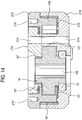
- Figures 13 and 14 illustrate a third preferred embodiment of the member for controlling the direction of travel of a vehicle, and in particular the corresponding hub 212 of this.
- the third preferred embodiment of the member for controlling the direction of a vehicle also comprises, not particularly illustrated in the accompanying drawings, a steering wheel for controlling the direction of a nautical vehicle, or boat, which comprises a respective rotatable body, which can be manually operated by the skipper of the vehicle for controlling the direction of the vehicle and which is operatively connectable to means defining, or determining, the direction of travel of the vehicle.
- the third preferred embodiment of the member for controlling the direction of a vehicle also comprises respective means, or hub, 212 for supporting the rotatable body which can be operated manually, which comprise means 214 fixed to the structure of the vehicle, which rotatably support respective means 216 for supporting, or coupling, the rotatable body which can be operated manually.
- this preferred third embodiment of the member for controlling the direction of a vehicle also comprises means 214 fixed to the structure of the vehicle which support corresponding means 218 supporting corresponding means which can be used, in particular which can be operated and/or viewed, by the skipper, which remain fixed during the rotations of the rotatable body, in a similar fashion to that described previously with regard to the first and second preferred embodiments.
- the hub 212 comprises, as illustrated, means for transmitting the motion which are also in the form of a corresponding longitudinal body 15, which is hollow for the passage and the coupling in a rotary fashion of a corresponding spindle (not illustrated in Figures 13 and 14 ), of the system for controlling the means which determine the direction of travel of the vehicle, and in any case in a similar fashion to that described previously with regard to the first and second preferred embodiments.
- the third preferred embodiment comprises fixed means or base 214 for fixing to the structure or frame of the vehicle nautical which define corresponding rotatable support means for the transmission means 15, as described in more detail below.
- the fixed means, or base, 214 define means for fixing to the frame of the nautical vehicle the rotatable supporting means for the means 216 for supporting, or coupling, the rotatable body which can be operated manually and fixed supporting means of the corresponding means 218 supporting the means which can be used, in particular which can be operated and/or viewed, by the skipper.
- the base means 214 comprise a respective disc-shaped body 214', from which extends axially a respective protrusion 215, in particular arc shaped and of variable radial thickness, the disc-shaped body 214' having a cavity 4' open axially, which is delimited by a respective inner surface, especially cylindrical, 215', on which are supported corresponding bearing means 15' for the transmission means 15.
- the transmission means 15 are also in the form of a corresponding hollow elongate element, which has an internal toothing 155 for coupling with the spindle of the drive chain, the spindle, however, not being illustrated in the accompanying drawings.
- a ring gear 151 is also supported or made outside the elongate member 15 for meshing with a respective drive gear wheel 161 for defining corresponding means for multiplying the transmission ratio between the rotatable body and the transmission means 15.
- the cavity 4' is positioned off-centre relative to the centre of the base body 214.
- the protrusion 215' has respective means 014 for the passage of the corresponding connections for the means which can be used by the skipper, the means for passage 014 extending in the disc-shaped base body 214'.
- the means for the passage of the corresponding connections are in the form of a corresponding longitudinal hole 014 axially open, which, preferably, opens at the zone of greatest thickness of the axial protrusion 215.
- the hole or opening 014 for the passage of the corresponding connections for the means which can be used by the skipper has a transversal oblong shape, in particular extending along a tangential direction, or at a right angle to the corresponding radius of curvature emanating from the respective longitudinal axis of the supporting body, or hub, 212.
- the short axial protrusion 215 has an arc shape and extends for a certain circumferential stretch around the opening 4' provided in the disc-shaped body 214'.
- a respective outer annular containment wall which is denoted in the drawings with the reference numeral 225, and which is radially spaced from the axial protrusion 215.
- the outer containment wall 225 extends axially beyond the free end of the axial protrusion 215.
- the axial protrusion 215 also comprises corresponding hole means 249, in particular in the form of a first and a second hole provided at the sides of the opening 014 for the passage of the corresponding connection cables, in which are screwed corresponding means, in particular screws 248, 248, for coupling the base body 214, of the means 218 which support the means which can be used by the skipper.
- the base means 214 are coupled longitudinally and directly with the means 218 supporting the means which can be used by the skipper.
- the means 218 supporting the means which can be used by the skipper are in the form of a disc-shaped body, preferably flat, or flattened, having corresponding hole means 219, 219 for the passage of the screw means 248, 248 for retaining the means 218 supporting the means which can be used by the skipper to the fixed supporting means 214.
- the disc-shaped body 218 has a respective cavity 4' open axially, which is delimited by a respective inner surface, in particular cylindrical, 215' on which a corresponding cylindrical sliding body 15" is supported for the other end of the transmission means 15.
- a respective inner surface in particular cylindrical, 215' on which a corresponding cylindrical sliding body 15" is supported for the other end of the transmission means 15.
- the other ends of the transmission means 15 might also be supported rotatably, rather than by the bearing 15', by a corresponding cylindrical sliding body, similar to the cylindrical sliding body 15".
- the cavity 4' in this disc-shaped body 218 is also positioned off-centre, relative to the centre of the hub 212.
- this disc-shaped body 218 there are respective means 014 for the passage of the corresponding connections for the means which can be used by the skipper, which connect to the means which can be used by the skipper and which are in the form of a corresponding longitudinal hole 014 axially open, which, preferably, has a transversal oblong shape, in particular extending along a tangential direction, or at a right angle to the corresponding radius of curvature emanating from the respective longitudinal axis of the supporting body, or hub, 212.
- the means 216 for supporting, or coupling, the rotatable body which can be operated manually advantageously comprise a flanged body 2160 having corresponding holes 216' for coupling the rotatable body, or steering wheel, which can be operated manually, a corresponding sleeve, or cylindrical element, 2161 extending from the flanged body, having an internal cavity in which an internal toothing 160 is made, defining a respective conductor gear wheel, meshed with a corresponding driven gear wheel 151, which is integral, in particular is made as one, with the motion transmission means 15.
- the means 216 for supporting, or coupling, the rotatable body which can be operated manually are supported in a slidable or rotatable manner by the base means, thanks to a corresponding cylindrical sliding body 16', which is interposed between the outer wall of the sleeve 2161, defining the inner toothing 160, and the inner surface of the containment wall 225 of the base body 214.
- corresponding flattened annular sliding bodies 16" and 16'" are interposed between corresponding transversal surfaces of the means 216 for supporting and coupling the rotatable body which can be operated manually and opposite transversal surfaces, respectively, of the base body 214 and the means 218 supporting the means which can be used by the skipper.
- the cavity means 014 for the passage of the corresponding connections, in particular electrical, for connecting the means 218 for supporting the means which can be used by the skipper and the cavity means 014 provided in the base body 214 are aligned with each other and each provided on the direct extension of the others.
- Figures 15 and 16 illustrate a third preferred embodiment of the member for controlling the direction of travel of a vehicle, in particular the corresponding hub 312 of this.
- the fourth preferred embodiment of the member for controlling the direction of a vehicle also comprises, not particularly illustrated in the accompanying drawings, a steering wheel for controlling the direction of a nautical vehicle, or boat, which comprises a respective rotatable body, which can be manually operated by the skipper of the vehicle for controlling the direction of the vehicle and which is operatively connectable to means defining, or determining, the direction of travel of the vehicle.
- the fourth preferred embodiment of the member for controlling the direction of a vehicle also comprises respective means, or hub, 312 for supporting the rotatable body which can be operated manually, which comprise means 314 fixed to the structure of the vehicle, which rotatably support respective means 216 for supporting, or coupling, the rotatable body which can be operated manually.
- this preferred fourth embodiment of the member for controlling the direction of a vehicle also comprises means 314 fixed to the structure of the vehicle which support corresponding means 318 supporting corresponding means which can be used, in particular which can be operated and/or viewed, by the skipper, which remain fixed during the rotations of the rotatable body, in a similar fashion to that described previously with regard to the previous preferred embodiments.
- the hub 212 comprises, as illustrated, means for transmitting the motion which are also in the form of a corresponding longitudinal body 15, which is hollow for the passage and the coupling in a rotary fashion of a corresponding spindle (not illustrated in Figures 15 and 16 ), of the system for controlling the means which determine the direction of travel of the vehicle, and in any case in a similar fashion to that described previously with regard to the first and second preferred embodiments.
- the fourth preferred embodiment comprises fixed means or base 314 for fixing to the structure or frame of the vehicle nautical and which define corresponding rotatable support means for the transmission means 15, as described in more detail below.
- the fixed means, or base, 314 define means for fixing to the frame of the nautical vehicle the rotatable supporting means for the means 216 for supporting, or coupling, the rotatable body which can be operated manually and fixed supporting means of the corresponding means 318 supporting the means which can be used, in particular which can be operated and/or viewed, by the skipper.
- the base means 314 comprise a respective disc-shaped body 314', from which extends axially a respective short protrusion 315, in particular arc shaped and of variable radial thickness, the disc-shaped body 314' having a cavity 4' open axially, which is delimited by a respective inner surface, especially cylindrical, 315', on which are supported corresponding sliding means 15' for the transmission means 15, in particular in the form of a corresponding cylindrical annular sliding body 15'.
- corresponding bearing means in the same way as illustrated in relation to the third preferred embodiment described above.
- the transmission means 15 are also in the form of a corresponding hollow elongate element, which has an internal toothing 155 for coupling with the spindle of the drive chain, the spindle, however, not being illustrated in the accompanying drawings.
- a ring gear 151 is also supported or made outside the elongate member 15 for meshing with a respective drive gear wheel 161 for defining corresponding means for multiplying the transmission ratio between the rotatable body and the transmission means 15.
- the cavity 4' provided in the base body 314 is positioned off-centre relative to the centre of the base body 314.
- the short protrusion 315' defines respective means 014 for the passage of the corresponding connections for the means which can be used by the skipper, the means for passage 014 extending in the disc-shaped base body 314'.
- the means for the passage of the corresponding connections are in the form of a corresponding longitudinal hole 014 axially open, which, preferably, opens at the zone of greatest thickness of the short axial protrusion 315.
- the hole or opening 014 for the passage of the corresponding connections for the means which can be used by the skipper has a transversal oblong shape, in particular extending along a tangential direction, or at a right angle to the corresponding radius of curvature emanating from the respective longitudinal axis of the supporting body, or hub, 312.
- the short axial protrusion 315 has an arc shape and extends for a certain circumferential stretch around the opening 4' provided in the disc-shaped body 314'.
- a respective outer annular containment wall which is denoted in the drawings with the reference numeral 325, and which is radially spaced from the axial protrusion 315.
- the outer containment wall 325 extends axially well beyond the free end of the axial protrusion 315.
- the axial protrusion 315 also comprises corresponding hole means 349, in particular in the form of a first and a second hole provided at the sides of the opening 014 for the passage of the corresponding connection cables, in which are screwed corresponding means, in particular screws 248, 248, for coupling the base body 248, of the means 318 which support the means which can be used by the skipper.
- the base means 314 are coupled longitudinally and directly with the means 318 supporting the means which can be used by the skipper.
- the means 318 supporting the means which can be used by the skipper are in the form of a disc-shaped body, preferably flat, or flattened, having corresponding hole means 319 for the passage of the screw means 248, 248 for retaining the means 318 supporting the means which can be used by the skipper to the fixed supporting means 314.
- the disc-shaped body 318 has a respective cavity 4' open axially, which is delimited by a respective inner surface, in particular cylindrical, 315' on which a corresponding cylindrical annular sliding body 15" is supported for the other end of the transmission means 15.
- the cavity 4' in this disc-shaped body 318 is also positioned off-centre, in particular relative to the centre of the hub 312.
- the means 318 supporting the means which can be used by the skipper have a corresponding axial protrusion 415, in particular arc shaped and with a variable radial thickness, which extends from the disc-shaped body 318.
- the axial protrusion 415 has a shape which is specular or coincident with that of the short axial protrusion 315 which is provided on the base body 314 with which it touches, as illustrated in Figure 16 .
- the axial protrusion 415 has an arc shape and extends for a certain circumferential stretch around the opening 4' provided in the disc-shaped body 318.
- this disc-shaped body 318 there are respective means 014 for the passage of the corresponding connections for the means which can be used by the skipper, which connect to the means which can be used by the skipper and which are in the form of a corresponding longitudinal hole 014 axially open, which, preferably, has a transversal oblong shape, in particular extending along a tangential direction, or at a right angle to the corresponding radius of curvature emanating from the respective longitudinal axis of the supporting body, or hub, 212.
- the longitudinal hole 014 extends in the zone of greatest thickness of the short axial protrusion 415.
- the means 216 for supporting, or coupling, the rotatable body which can be operated manually are the same as those of the third preferred embodiment and advantageously comprise a flanged body 2160 having corresponding holes 216' for coupling the rotatable body, or steering wheel, which can be operated manually, a corresponding sleeve, or cylindrical element, 2161 extending from the flanged body, having an internal cavity in which an internal toothing 160 is made, defining a respective conductor gear wheel, meshed with a corresponding driven gear wheel 151, which is integral, in particular is made as one, with the motion transmission means 15.
- the means 216 for supporting, or coupling, the rotatable body which can be operated manually are supported in a slidable or rotatable manner by the base means, thanks to a corresponding cylindrical annular sliding body 16', which is interposed between the outer wall of the sleeve 2161, defining the inner toothing 160, and the inner surface of the containment wall 325 of the base body 314.
- corresponding flattened annular sliding bodies 16" and 16'" are interposed between corresponding transversal surfaces of the means 216 for supporting and coupling the rotatable body which can be operated manually and opposite transversal surfaces, respectively, of the base body 114 and the means 318 supporting the means which can be used by the skipper.
- the cavity means 014 for the passage of the corresponding connections, in particular electrical, for connecting the means 318 for supporting the means which can be used by the skipper and the cavity means 014 provided in the base body 314 are aligned with each other and each provided on the direct extension of the others.
- the respective hub 12, 112, 212, 312 of the above-mentioned preferred embodiments is in the form of a particularly compact body, in particular longitudinally, which allows the member for controlling the direction of travel to be applied on vehicles already configured without modifying the steering arrangement and/or the appearance of the vehicle.
- the hub 12, 112, 212, 312 can be inserted, in an off centre or offset manner on a corresponding spindle for transmission of the chain controlling the means for steering the nautical vehicle.
Landscapes
- Engineering & Computer Science (AREA)
- Mechanical Engineering (AREA)
- Chemical & Material Sciences (AREA)
- Combustion & Propulsion (AREA)
- General Engineering & Computer Science (AREA)
- Ocean & Marine Engineering (AREA)
- Transportation (AREA)
- Mechanical Control Devices (AREA)
- Power Steering Mechanism (AREA)
- Gear Transmission (AREA)
- Radar Systems Or Details Thereof (AREA)
Description
- This invention relates to a member to control the direction of a vehicle, preferably to control the direction of a nautical vehicle.
- There are prior art members preferably in the form of respective steering wheels to control the direction of a nautical vehicle, or boat, which comprise a respective rotatable body which can be manually operated by the skipper of the nautical vehicle to control the direction of the vehicle and is operatively connectable to means defining, or determining, the direction of travel of the vehicle.
- As is known, the rotatable bodies, or steering wheels, for controlling the direction of the nautical vehicle are operated for modifying the direction of travel of the vehicle in such a way as to perform ample rotations, that is to say, even in such a way as to perform several complete revolutions.
- As a result, a plurality of means, or components, which can be used by the skipper during the manoeuvre, for example elements, or pushbuttons, for controlling corresponding instruments, apparatuses and/or devices of the vehicle and/or of the control displays are positioned in a fixed manner on the dashboard of the nautical vehicle, and therefore in an inconvenient position to be viewed or to be reached and the skipper must therefore change his/her viewpoint and/or release the rotatable body to operate these, with a consequent high risk of performing incorrect manoeuvres.
- In addition, the arrangement of the elements, or pushbuttons, for controlling corresponding instruments, apparatuses and/or devices of the vehicle, or respective control displays, on the dashboard of the nautical vehicle, makes it necessary to build boats which have large control dashboards, which cannot therefore be easily used for other functions, and, moreover, they must be provided with an extremely large number of cables for the respective connections, in particular defined by respective electrical cables.
WO 2007/080357 A1 shows a steering wheel arrangement for a car in which the steering wheel has a central, non-rotating hub, around which an outer peripheral part of the steering wheel may be rotated. In general, in particular in the nautical sector, the need is felt solutions which do not impact excessively on the appearance of the vehicle, in particular which occupy a limited space and which are quick and easy to set up. - This invention therefore proposes a new solution as an alternative to the solutions known up to now and, more specifically, proposes to overcome one or more of the above mentioned drawbacks and/or problems and/or to meet one or more of the needs felt in the trade or inferable from the above. A hub according to independent claim 1 is therefore provided.
- By means of an hub according to independent claim 1, it is possible for the skipper to have easy access, also visual, to the means which can be used, in particular which can be operated and/or viewed, by the skipper, during the steps of moving the vehicle, in particular of the nautical vehicle or boat, thus without the risk of performing incorrect manoeuvres.
- These and other innovative aspects are set out in the appended claims and the technical features and advantages are also apparent from the detailed description which follows of non-limiting example embodiments of it with reference to the accompanying drawings, in which:
-
Figures 1A and 1B illustrate respective front views of a rotary control member, in different working positions, according to a preferred embodiment of this invention; -
Figure 2 illustrates an exploded perspective view of the components of the first preferred embodiment of the hub used in the control member according to this invention; -
Figure 3 illustrates a plan view from above of the first preferred embodiment of the supporting hub; -
Figure 4 illustrates a cross section through the line IV - IV ofFigure 3 relative to the first preferred embodiment of the supporting hub; -
Figure 5 illustrates a side view of the first preferred embodiment of the hub; -
Figure 6 illustrates a plan view from below of the first preferred embodiment of the hub; -
Figure 7 illustrates a cross section of the first preferred embodiment of the hub through the line VII-VII ofFigure 3 ; -
Figure 8 illustrates a vertical longitudinal section of a second preferred embodiment of the direction control member according to this invention; -
Figure 9 illustrates an exploded perspective view of a second preferred embodiment of the supporting hub used in the control member ofFigure 8 ; -
Figure 10 illustrates an exploded perspective view of the second preferred embodiment of the means, from the side opposite that of theFigure 9 ; -
Figure 11 illustrates a perspective view of the supporting hub of the second preferred embodiment of the control member; -
Figure 12 illustrates a plan view from above of the supporting hub of the second preferred embodiment of the control member; -
Figure 13 illustrates an exploded perspective view of a third preferred embodiment of means for a control member according to this invention; -
Figure 14 illustrates a longitudinal section of the third preferred embodiment of the means for a control member according to this invention; -
Figure 15 illustrates an exploded perspective view of a fourth preferred embodiment of means for a control member according to this invention; -
Figure 16 illustrates a longitudinal section of the fourth preferred embodiment of a hub for a control member according to this invention. - With reference to the accompanying drawings, a preferred embodiment of a
member 10 for controlling the direction of a vehicle, preferably in the form of a steering wheel for controlling the direction of a nautical vehicle, or boat, comprises arotatable body 11, which can be manually operated by the skipper of the vehicle for controlling the direction of the vehicle and which is operatively connectable to means defining, or determining, the direction of travel of the vehicle, for example defined by a corresponding blade of the rudder of the boat or other device. - Advantageously, this
member 10 for controlling the direction of travel of a vehicle comprises respective means, or hub, 12 for supporting therotatable body 11, which comprise respective fixedsupporting means 14, which are connectable to the fixed structure of the vehicle, and which support, in a rotatable fashion, in particular in a freely rotatable fashion, respective means 16 for supporting, or coupling, therotatable body 11 which can be operated manually. - Advantageously, the
means 14 fixed to the structure of the vehiclesupport corresponding means 18 which can be used, in particular which can be operated and/or viewed, by the skipper, which remain fixed during the rotations of therotatable body 11 which can be operated manually. - More specifically, advantageously, as will become clearer as this description continues, the
means 18 which can be used by the skipper during the driving of the vehicle comprise, or may comprise, one or more elements, or pushbuttons, 19, which are designed to control the corresponding instruments, apparatuses and/or devices of the vehicle. - Further advantageously, the means which can be used by the skipper pilot from the comprise, or may comprise, a respective display, in particular electronic.
- Also, advantageously, as illustrated in
Figures 1A and 1B , themeans 18 which can be used by the skipper comprise, or may comprise, a respective surface designed to bear a corresponding graphical reproduction, for example reproducing arespective logo 21. - As may be inferred, the means, or hub, 12 house, in a freely rotatable fashion, the
corresponding means 15 for transmitting the rotating motion of therotatable body 11 which can be operated manually towards the means which define, or determine, the direction of travel of the vehicle. - Advantageously, as illustrated, the means, or hub, 12 for supporting the
rotatable body 11 which can be operated manually comprise means 150, 160 for multiplying the transmission ratio between therotatable body 11 and themeans 15 for transmitting the rotating motion of therotatable body 11 which can be operated manually. - Advantageously, the multiplying means comprise a respective
drive gear wheel 161 having aninner toothing 160, which is integral with, or integrally connected in a rotary fashion with, supporting, or coupling, means of therotary body 11. - As illustrated, the
drive gear wheel 161 meshes with a corresponding drivengear wheel 151, which is integral, in particular is made as one, with themeans 15 for transmitting the motion. - Advantageously, the means for transmitting the motion are in the form of a corresponding
longitudinal body 15, which is supported in a freely rotatable manner by thefixed means 14 and which is connectable coaxially to a corresponding spindle, not illustrated in the accompanying drawings, defining part of the chain for driving the means defining, or determining, the direction of travel of the vehicle. - More specifically, the
transmission element 15 has, in a central longitudinal position, the toothing, or ring gear, 150 and is supported by corresponding bearings 15', 15', to the longitudinal sides of thetoothing 150, the bearings 15', 15' being interposed between thetransmission element 15 and thefixed body 14 of the supporting means, or hub, 12. - As illustrated, the means, or hub, 12 are in the form of a squat body having a respective longitudinal axis "L", relative to which the squat body extends circumferentially and which also define the axis of rotation of the
rotatable body 11 which can be operated manually, that is, in particular, the supporting or coupling means 16. - As illustrated, the
means 15 for transmitting the motion are located in a position which is off centre relative to the longitudinal axis of the means, or hub, 12 for supporting therotatable body 11 which can be operated manually, being rotatable relative to a respective longitudinal axis which is parallel the main axis "L" and radially spaced relative to it. Advantageously, the fixedmeans 14 of the hub comprise base means, or base, 141, 142, for fixing to the structure of the vehicle, for example through corresponding holes for insertion of corresponding connecting screws, which are made in the base and which are labelled in the drawings withreference numeral - The base means, or base, 141, 142 define a corresponding cavity 4' for the passage of a corresponding spindle of the drive chain, which is connected integrally to the
means 15 of transmitting the angular movement imparted by steering wheel orrotatable body 11 which can be operated manually. Advantageously, the fixedmeans 14 also comprise means 143 for supporting themeans 18 which can be used by the skipper. - More specifically, as illustrated, the means for supporting the
means 18 which can be used by the skipper are in the form of a respective supportingbody 143. - As illustrated, the
means 143 for supporting themeans 18 which can be used by the skipper have a correspondinglongitudinal cavity 4 for housing the transmission means 15. - As illustrated, the fixed base of the hub comprises, in particular, a longitudinal
outer plate 141, for closing thehub body 12, and aplate 142 which is more inside, which is integrally connected, bycorresponding screws 1412, to theouter plate 141. - Advantageously, the base means 141, 142 are coupled longitudinally with the
means 143 for supporting themeans 18 which can be used by the skipper. - More specifically, the fixed base, in particular the
inner plate 142 of this, couples longitudinally with themeans 143 for supporting themeans 18 which can be used by the skipper, defining, with themeans 143 for supporting, thehousing cavity 4 for the transmission means 15, in particular defining overall a corresponding cylindrical surface for engaging the bearings 15' for rotatably supporting the transmission means 15. - More specifically, the
base means 143 for supporting themeans 18 which can be used by the skipper using corresponding integral connectingscrews 1413. - Advantageously, thus, the
control member 10 comprises means, or hub, 12 for supporting therotatable body 11 which can be operated manually, in which there are cavity means 014 for the passage of the corresponding connections for themeans 18 which can be used by the skipper. Advantageously, the fixedmeans 14, in particular the fixed supportingbase means 143 for supporting themeans 18 which can be used by the skipper, comprise cavity means 014 for the passage of the corresponding connections, preferably electrical, and in particular in the form of respective flexible cables, which connect to themeans 18 which can be used by the skipper. - More specifically, the cavity means 014 for the passage of the corresponding electrical connections comprise a respective
longitudinal hole 014, which is made in thefixed means 14, in particular in the fixed supportingbase means 143 for supporting themeans 18 which can be used by the skipper. - Advantageously, the
longitudinal hole 014, defining the cavity means for the passage of the corresponding connections, is provided in a position which is off centre relative to the longitudinal axis "L", of the means, or hub, 12 for supporting therotatable body 11 which can be operated manually. - As illustrated, the
hole 014 for the passage of the corresponding connections has a transversal oblong shape, in particular extending along a tangential direction, or at a right angle to the corresponding radius of curvature emanating from the longitudinal axis of the supporting body, or hub, 12. - Advantageously, as illustrated, the fixed
means 14, in particular themeans 143 for supporting themeans 18 which can be used by the skipper, engage and support, at the respective longitudinal end which faces, in use, towards the skipper, or opposite the one engaging thefixed base end body 140, preferably with a circumferential profile. - The fixed
end body 140, if necessary made of plastic material, defines a respective supporting surface for a corresponding graphical reproduction, or logo, 21, or, in a different embodiment, in the form of a corresponding display, in particular electronic, which can be used by the skipper. - As illustrated, the
rotatable body 11 which can be operated manually comprises a respectivecircumferential body 111 and corresponding spoke means 112, in particular in the form of four spokes in pairs respectively side by side, which extend radially relative to the supporting means, or hub, 12 and connecting to the supporting means, or hub, 12, more specifically to therotatable means 16 for supporting, or coupling, therotatable body 11 which can be operated manually. - Advantageously, the
means 16 for supporting, or coupling, therotatable body 11 which can be operated manually comprise arespective body 162 for fixing therotatable body 11 which can be operated manually. - More specifically, as illustrated, the means, or body, 162 for fixing the
rotatable body 11 which can be operated manually are in the form of aflanged body 162. - More specifically, the
flange 162, for fixing therotatable body 11 which can be operated manually, is provided at the longitudinal end, which faces in use towards the skipper, and defines a corresponding outer surface, or edge, 161' of the upper face of the supporting means, or hub, 12. - As illustrated, the
flange 162 for fixing therotatable body 11 which can be operated manually is integral, in particular rotatable, with thedrive ring gear 161 of the multiplying means. - More specifically, as illustrated, the
outer flange 162 is fixed to thedrive ring gear 161 by correspondingscrews 1621. - In a different embodiment, it is also imaginable that the
outer flange 162, for fixing therotatable body 11, defines, or is as one piece with, thedrive ring gear 160 of the means for multiplying, or transmission, of the rotation of therotatable body 11. - As illustrated, the multiplying
ring gear 160, and/or theflange 162 for fixing therotatable body 11 which can be operated manually, is supported rotatably, by sliding, by the fixed means 14. - More specifically, there are respective sliding
annular bodies body 161 which supports thering gear 160. - It would also be imaginable to prepare special bearing means between the
ring gear 160, and/or theflange 162 for fixing therotatable body 11 which can be operated manually, and the fixed supportingmeans 14. - As illustrated, the
hub 12 also comprises an outer annular containment wall, which is labelled in the drawings with thereference numeral 25. - As may be inferred from drawings, the transmission means 15 are in the form of a corresponding hollow elongate element, which has an internal groove or
toothing 155 for coupling with the spindle of the drive chain, the spindle, however, not being illustrated in the accompanying drawings. However, it will be understood that the coupling between the transmission means 15 and the spindle of the drive chain might be achieved in any desired manner, for example by corresponding conical surfaces which can be coupled to each other or respective key for fastening during rotation. Considering now in more detailFigures 1A and 1B , it may be inferred that, advantageously, themeans 18 which can be used by the skipper are located inside thecircumferential body 111 of therotatable control body 11. More specifically, advantageously, as illustrated, means 18 which can be used by the skipper extend from the means, or hub, 12 supporting therotatable body 11. - Advantageously, as illustrated, the 18 which can be used by the skipper, in particular comprising one or more elements, or pushbuttons, 19 for controlling corresponding instruments, apparatuses and/or devices of the vehicle, extend radially to and/or from the means, or hub, 12 supporting the
rotatable body 11. - Advantageously, as illustrated, the 18 which can be used by the skipper, in particular comprising one or more elements, or pushbuttons, 19 for controlling corresponding instruments, apparatuses and/or devices of the vehicle, extend laterally from the means, or hub, 12 supporting the
rotatable body 11. - Advantageously, as illustrated, the 18 which can be used by the skipper, in particular comprising one or more elements, or pushbuttons, 19 for controlling corresponding instruments, apparatuses and/or devices of the vehicle, extend at sides, in particular transversal opposite the means, or hub, 12 supporting the rotatable body.
- Advantageously, there are a first and a
second plurality - The first and
second plurality - Advantageously, as illustrated, the
means 18 which can be used by the skipper, in particular comprising one or more elements, or pushbuttons, 19 for controlling corresponding instruments, apparatuses and/or devices of the vehicle, which are positioned parallel to the plane on which thecircumferential body 111 of therotatable body 11 which can be operated manually lies. - Advantageously, the
means 18 which can be used by the skipper, in particular one or more of the elements, or pushbuttons, 19 for controlling corresponding instruments, apparatuses and/or devices of the vehicle, are supported by acorresponding base unit 190, which is, in particular, supported by corresponding arm means, in particular in the form of a first and asecond arm rotary body 11 which can be operated manually. - More specifically, as illustrated, the
base 190 supports a plurality of the elements orpushbuttons 19 for controlling corresponding instruments, apparatuses and/or devices of the vehicle, positioned along one or more transversal rows and/or along one or more perpendicular rows. More specifically, as illustrated, there can be three transversal rows of the elements, or pushbuttons, 19 and three perpendicular rows of the elements, or push buttons, 19. - Further advantageously, the
means 18 which can be used by the skipper, in particular when they are in the form of a respective display, preferably electronic, and/or a respective surface designed to bear a correspondinggraphical reproduction 21, are located at the central steering column zone of thecircumferential body 111 of therotatable body 11. - According to a further advantageous aspect, the
means 18 which can be used by the skipper, in particular when they are in the form of a respective display, preferably electronic, and/or a surface designed to bear a correspondinggraphical reproduction 21, are located at the upper face of the means, or hub, 12 for supporting therotatable body 11 which can be operated manually. - In this way, the means which can be used by the skipper are easily accessible or, in any case, can be seen by the skipper.
- Thanks to this
steering control body 10, orrespective hub 12, it is possible to avoid positioning a plurality, or the totality, of elements, or pushbuttons, on the dashboard for controlling corresponding instruments, apparatuses and/or devices of the vehicle and/or the respective control display, in particular electronic. The dashboards can therefore be dimensioned in a more suitable manner or with reduced size, or can be easily used for other functions, above all avoiding the provision on the dashboard of an extremely large number of cables for respective connections, in particular for respective electrical cables. - A second embodiment of the
member 100 for controlling the direction of a vehicle is illustrated inFigures 8 and12 , in which the components which are similar or equivalent to those of the first embodiment are denoted by the same reference numerals used in relation to the first preferred embodiment and will not be commented in detail again so as to avoid making this description too lengthy. - As may be inferred from
Figures 8 to 12 , the second preferred embodiment of themember 100 for controlling the direction of a vehicle is, as illustrated, also preferably in the form of a steering wheel for controlling the direction of a nautical vehicle, or boat, and comprises arotatable body 11, which can be manually operated by the skipper of the vehicle for controlling the direction of the vehicle and which is operatively connectable to means defining, or determining, the direction of travel of the vehicle. - As illustrated, the second preferred embodiment of the
member 100 for controlling the direction of a vehicle comprises respective means, or hub, 112 for supporting therotatable body 11 which can be operated manually, which comprise means 14 fixed to the structure of the vehicle, which rotatably support respective means 16 for supporting, or coupling, therotatable body 11 which can be operated manually. - Further, as illustrated, this preferred embodiment of the
member 100 for controlling the direction of a vehicle also comprises means 14 fixed to the structure of the vehicle which support corresponding means 18 which can be used, in particular which can be operated and/or viewed, by the skipper, themeans 18 remaining fixed during the rotations of therotatable body 11, which are identical to those illustrated in the first preferred embodiment of the member which are therefore not described again in detail. - More specifically, the
hub 112 comprises, as illustrated, means for transmitting the motion which are also in the form of a correspondinglongitudinal body 15, which is hollow for the passage and the coupling in a rotary fashion of a corresponding spindle A of the system for controlling the means which determine the direction of travel of the vehicle. - In particular, as illustrated, the spindle A protrudes on the side opposite to that of insertion in the
longitudinal body 15, that is, above thelongitudinal transmission body 15, and has on the respective projecting part of the spindle A a corresponding thread on which is screwed acorresponding securing nut 159, which, using a corresponding washer 159', engages and clamps against the upper surface of thetransmission body 15. Advantageously, the second preferred embodiment comprises fixed means, or base, 14 for fixing to the structure or frame T of the nautical vehicle which comprise first and second base means 1410, 1420, which are made integral with each other, in particular by respective connectingscrews 1412, which are inserted into respective holes 1410', 1420' which are provided in the first and second base means 1410, 1420. - More specifically, the base means 1410, 1420 define corresponding rotatable support means for the transmission means 15, as described in more detail below.
- Also, as illustrated, the first and second base means 1410, 1420 respectively define means for fixing to the frame T of the nautical vehicle the rotatable supporting means for the
means 16 for supporting, or coupling, therotatable body 11 which can be operated manually and fixed supporting means of the corresponding means 18 which can be used, in particular which can be operated and/or viewed, by the skipper. - More specifically, as illustrated, the first base means are defined by a
respective body 1410, which is in particular in the form of a flanged body, preferably flat, or flattened, for coupling, thanks to correspondingscrews 1410T which are inserted in correspondingholes 1410" of thebody 1410, to the frame T of the nautical vehicle. - Moreover, the second base means are defined by a
respective body 1420, in particular in the form of a correspondingflanged body 1420a, from which extends axially a respective hollow sleeve and with a variable radial thickness, in particular with an asymmetrical radial thickness, 1420b, which has an internal axial cavity 4', which is delimited by a respective inner surface, especially cylindrical, 1425' on which are supported corresponding bearing means 15' for the transmission means 15 and anouter profile 1425" for supporting corresponding bearing means 15' for rotatably supporting means 16 for supporting, or coupling, therotatable body 11 which can be operated manually. - However, it will be understood that, according to a further preferred embodiment not illustrated in the accompanying drawings, it would also be imaginable that the first and
second base body - Advantageously, also in this second preferred embodiment, the base means 1410, 1420 are coupled longitudinally with the
means 1430 for supporting themeans 18 which can be used by the skipper. - Advantageously, the second base means, or body, 1420 have corresponding hole means, in particular defined by a first and a second hole 1420', 1420', preferably extending inside the
sleeve portion 1420b of these, the hole means being provided for insertion of corresponding screw means, in particular in the form of a first and a second screw, 1413, 1413 for retaining means, in particular bushing means, 1430, 1430 for fixed support of corresponding means 18 which can be used by the skipper, which are described in more detail below. - Advantageously, in this second preferred embodiment of the member, or hub, 100, the
means 14 for supporting themeans 18 which can be used by the skipper are in the form of respective bushing means, and in particular in the form of a first and asecond bushing circumferential body 210 which, in turn, defines a respective inner seat for housing themeans 18 which can be used by the skipper. As illustrated, thebushes - As illustrated, advantageously, the
means 14 for supporting themeans 18 which can be used by the skipper also comprise a disc-shaped body, preferably flat, or flattened, 1430b for engaging the respective end, in particular a lower end, of the bushing means 1430, 1430, which, in particular, engage on the corresponding body orsleeve 1420b of the second base means, 1420, and which, at the zone for engaging the bushing means 1430, 1430 has corresponding hole means 1430f for the passage of the screw means 1413 for retaining the bushing means 1430 on the base, or respective body, means 1420. - Advantageously, as illustrated, the disc-shaped
body 1430b for engaging the respective end of the bushing means 1430, 1430 has a correspondinglongitudinal cavity 4 for housing the transmission means. Advantageously, the disc-shapedbody 1430b for engaging the respective end of the bushing means 1430, 1430 has corresponding holes 2030' for insertingrespective screws 2030b inserted in correspondingholes 2030" of theasymmetrical sleeve 1420b, to which the disc-shapedbody 1430b is fixed. - In practice, the disc-shaped
body 1430b for engaging the respective end of the bushing means 1430, 1430 is fixed to the base means, or upper body of these, 1420. - In this second preferred embodiment of the member or
hub 100, themeans 16 for supporting, or coupling, therotatable body 11 which can be operated manually, advantageously, comprise a tubular body, in particular on the outside, 1620 for fixing therotatable body 11 which can be operated manually, that is to say, a circumferential central portion of the hub 111' of this, the fixing being performed, in particular, byrespective screws 1601 inserted in correspondingholes 1620f provided in the tubular body and in theflanged body 1621 which supports the multiplyingring gear 161, as will be described in detail below. - More specifically, as illustrated, advantageously, the tubular body, in particular external, 1620 supports a corresponding
flanged body 1621, which defines, or carries, the multiplyinggear wheel 161. - In particular, as illustrated, the
flanged body 1621 which defines the multiplyingring gear 161 is fixed to thetubular body 1620 by correspondingscrews 1601, which are inserted inrespective holes tubular body 1620 and in theflanged body 1621 which defines, or carries, thering gear 161. - As illustrated, advantageously, the outer
tubular body 1620 has an annular inner, or internally protruding, portion 1620' of reduced height relative to the outer tubular element, the inner annular portion 1620' defining a transversal surface, extending circumferentially, for supporting theflanged body 1621 defining, or carrying, the multiplyingring gear 161. - Further, the
tubular body 1620 also has a cylindricalinner surface 1620" of the annular inner portion 1620', the inner cylindrical surface engaging outside respective bearing means 15' for rotatably supporting therotatable control body 11. As illustrated, the innercylindrical surface 1620" of thetubular body 1620 has a respective annular shoulder 1625 for axially positioning and retaining the bearing means 15'. - More specifically, as illustrated, the disc-shaped
body 1430b, on which the bushing means 1430, rest is positioned, axially, below relative to theflanged body 1621 which defines, or carries, the multiplyingring gear 161 meshing with the corresponding gear ring of the transmission means 15. Advantageously, as illustrated, the bushing means 1430 for coupling therotatable body 11 which can be operated manually extend axially passing through theflanged body 1621 which defines, or carries, the multiplyingring gear 161. - Advantageously, as illustrated, the
asymmetrical sleeve 1420b of the respective base means, or body, 1420 has a corresponding external annular shoulder 1420'b for positioning the corresponding bearing means 15' for themeans 16 for supporting and coupling therotatable body 11 which can be operated manually and, also, a corresponding internalannular shoulder 1420"b for positioning the corresponding bearing means 15' for the transmission means 15. - As illustrated, on the outer surface of the cylindrical body defining the transmission means 15 and below the
ring gear 151 of these, there may be a corresponding Seeger type stop ring denoted by the reference S in the drawings. - Advantageously, also in this second preferred embodiment of the
member 100, there are cavity means 014 for the passage of the corresponding connections, in particular electric, of themeans 18 which can be used by the skipper, the cavity means 014 comprising a respectivelongitudinal hole 014 which is made in the fixed means 14, in particular in the fixed supporting means, or respective body, 1410 and/or 1420, in particular thelongitudinal hole 014 extending in the correspondingasymmetrical sleeve 1420b of the corresponding base body at the portion of greater radial thickness of this. Moreover, the cavity means 014 for the passage of the corresponding connections, in particular electric, of themeans 18 which can be used by the skipper, comprise a respectivelongitudinal hole 014 which extends in, or passes longitudinally through, the disc-shapedbody 1430b for supporting the bushing means 1430 for supporting and coupling themeans 18 which can be used by the skipper. - In practice, in this second embodiment of the
member 100, orhub 112, that is, in the corresponding means or bodies in which the cavity means 014 are provided, the latter are also provided in a position which is off centre relative to the longitudinal axis of the respective means or bodies or, overall, of thehub 112. -
Figures 13 and14 illustrate a third preferred embodiment of the member for controlling the direction of travel of a vehicle, and in particular thecorresponding hub 212 of this. - In
Figures 13 and14 , the components which are similar to those of the first and second embodiments are denoted by the same reference numerals and will not be commented in detail again so as to avoid making this description too lengthy. - As may be inferred from
Figures 13 to 14 , the third preferred embodiment of the member for controlling the direction of a vehicle also comprises, not particularly illustrated in the accompanying drawings, a steering wheel for controlling the direction of a nautical vehicle, or boat, which comprises a respective rotatable body, which can be manually operated by the skipper of the vehicle for controlling the direction of the vehicle and which is operatively connectable to means defining, or determining, the direction of travel of the vehicle. - As illustrated, the third preferred embodiment of the member for controlling the direction of a vehicle also comprises respective means, or hub, 212 for supporting the rotatable body which can be operated manually, which comprise means 214 fixed to the structure of the vehicle, which rotatably support
respective means 216 for supporting, or coupling, the rotatable body which can be operated manually. - Further, as illustrated, this preferred third embodiment of the member for controlling the direction of a vehicle also comprises
means 214 fixed to the structure of the vehicle which support corresponding means 218 supporting corresponding means which can be used, in particular which can be operated and/or viewed, by the skipper, which remain fixed during the rotations of the rotatable body, in a similar fashion to that described previously with regard to the first and second preferred embodiments. More specifically, thehub 212 comprises, as illustrated, means for transmitting the motion which are also in the form of a correspondinglongitudinal body 15, which is hollow for the passage and the coupling in a rotary fashion of a corresponding spindle (not illustrated inFigures 13 and14 ), of the system for controlling the means which determine the direction of travel of the vehicle, and in any case in a similar fashion to that described previously with regard to the first and second preferred embodiments. - Advantageously, the third preferred embodiment comprises fixed means or
base 214 for fixing to the structure or frame of the vehicle nautical which define corresponding rotatable support means for the transmission means 15, as described in more detail below. - In practice, as illustrated, the fixed means, or base, 214 define means for fixing to the frame of the nautical vehicle the rotatable supporting means for the
means 216 for supporting, or coupling, the rotatable body which can be operated manually and fixed supporting means of the corresponding means 218 supporting the means which can be used, in particular which can be operated and/or viewed, by the skipper. - More specifically, as illustrated, the base means 214 comprise a respective disc-shaped body 214', from which extends axially a
respective protrusion 215, in particular arc shaped and of variable radial thickness, the disc-shaped body 214' having a cavity 4' open axially, which is delimited by a respective inner surface, especially cylindrical, 215', on which are supported corresponding bearing means 15' for the transmission means 15. - As illustrated, the transmission means 15 are also in the form of a corresponding hollow elongate element, which has an
internal toothing 155 for coupling with the spindle of the drive chain, the spindle, however, not being illustrated in the accompanying drawings. - As illustrated, a
ring gear 151 is also supported or made outside theelongate member 15 for meshing with a respectivedrive gear wheel 161 for defining corresponding means for multiplying the transmission ratio between the rotatable body and the transmission means 15. - As illustrated, the cavity 4' is positioned off-centre relative to the centre of the
base body 214. - As illustrated, the protrusion 215' has
respective means 014 for the passage of the corresponding connections for the means which can be used by the skipper, the means forpassage 014 extending in the disc-shaped base body 214'. - Advantageously, the means for the passage of the corresponding connections, preferably electrical, and in particular in the form of respective flexible cables, which connect to the means which can be used by the skipper, are in the form of a corresponding
longitudinal hole 014 axially open, which, preferably, opens at the zone of greatest thickness of theaxial protrusion 215. - Also in this third preferred embodiment, the hole or opening 014 for the passage of the corresponding connections for the means which can be used by the skipper has a transversal oblong shape, in particular extending along a tangential direction, or at a right angle to the corresponding radius of curvature emanating from the respective longitudinal axis of the supporting body, or hub, 212.
- As illustrated, the short
axial protrusion 215 has an arc shape and extends for a certain circumferential stretch around the opening 4' provided in the disc-shaped body 214'. - Advantageously, in the third preferred embodiment, from the
base body 214 extends a respective outer annular containment wall, which is denoted in the drawings with thereference numeral 225, and which is radially spaced from theaxial protrusion 215. - As illustrated, the
outer containment wall 225 extends axially beyond the free end of theaxial protrusion 215. - The
axial protrusion 215 also comprises corresponding hole means 249, in particular in the form of a first and a second hole provided at the sides of theopening 014 for the passage of the corresponding connection cables, in which are screwed corresponding means, inparticular screws base body 214, of themeans 218 which support the means which can be used by the skipper. - In practice, advantageously, in the third preferred embodiment, the base means 214 are coupled longitudinally and directly with the
means 218 supporting the means which can be used by the skipper. - Advantageously, in the third preferred embodiment, the
means 218 supporting the means which can be used by the skipper are in the form of a disc-shaped body, preferably flat, or flattened, having corresponding hole means 219, 219 for the passage of the screw means 248, 248 for retaining themeans 218 supporting the means which can be used by the skipper to the fixed supporting means 214. - As illustrated, the disc-shaped
body 218 has a respective cavity 4' open axially, which is delimited by a respective inner surface, in particular cylindrical, 215' on which a corresponding cylindrical slidingbody 15" is supported for the other end of the transmission means 15. However, it will be understood that the other ends of the transmission means 15 might also be supported rotatably, rather than by the bearing 15', by a corresponding cylindrical sliding body, similar to the cylindrical slidingbody 15". - As illustrated, the cavity 4' in this disc-shaped
body 218 is also positioned off-centre, relative to the centre of thehub 212. - Moreover, in this disc-shaped
body 218 there arerespective means 014 for the passage of the corresponding connections for the means which can be used by the skipper, which connect to the means which can be used by the skipper and which are in the form of a correspondinglongitudinal hole 014 axially open, which, preferably, has a transversal oblong shape, in particular extending along a tangential direction, or at a right angle to the corresponding radius of curvature emanating from the respective longitudinal axis of the supporting body, or hub, 212. - In this third preferred embodiment of the member, or hub, the
means 216 for supporting, or coupling, the rotatable body which can be operated manually advantageously comprise aflanged body 2160 having corresponding holes 216' for coupling the rotatable body, or steering wheel, which can be operated manually, a corresponding sleeve, or cylindrical element, 2161 extending from the flanged body, having an internal cavity in which aninternal toothing 160 is made, defining a respective conductor gear wheel, meshed with a corresponding drivengear wheel 151, which is integral, in particular is made as one, with the motion transmission means 15. - The means 216 for supporting, or coupling, the rotatable body which can be operated manually are supported in a slidable or rotatable manner by the base means, thanks to a corresponding cylindrical sliding body 16', which is interposed between the outer wall of the
sleeve 2161, defining theinner toothing 160, and the inner surface of thecontainment wall 225 of thebase body 214. - Moreover, corresponding flattened annular sliding
bodies 16" and 16'" are interposed between corresponding transversal surfaces of themeans 216 for supporting and coupling the rotatable body which can be operated manually and opposite transversal surfaces, respectively, of thebase body 214 and themeans 218 supporting the means which can be used by the skipper. - Advantageously, as illustrated, the cavity means 014 for the passage of the corresponding connections, in particular electrical, for connecting the
means 218 for supporting the means which can be used by the skipper and the cavity means 014 provided in thebase body 214 are aligned with each other and each provided on the direct extension of the others. -
Figures 15 and16 illustrate a third preferred embodiment of the member for controlling the direction of travel of a vehicle, in particular thecorresponding hub 312 of this. - In
Figures 15 and16 , the components which are similar to those of the previous embodiments, and in particular to the third preferred embodiment, are denoted by the same reference numerals and will not be commented in detail again so as to avoid making this description too lengthy. - As may be inferred from
Figures 15 to 16 , the fourth preferred embodiment of the member for controlling the direction of a vehicle also comprises, not particularly illustrated in the accompanying drawings, a steering wheel for controlling the direction of a nautical vehicle, or boat, which comprises a respective rotatable body, which can be manually operated by the skipper of the vehicle for controlling the direction of the vehicle and which is operatively connectable to means defining, or determining, the direction of travel of the vehicle. - As illustrated, the fourth preferred embodiment of the member for controlling the direction of a vehicle also comprises respective means, or hub, 312 for supporting the rotatable body which can be operated manually, which comprise means 314 fixed to the structure of the vehicle, which rotatably support
respective means 216 for supporting, or coupling, the rotatable body which can be operated manually. - Further, as illustrated, this preferred fourth embodiment of the member for controlling the direction of a vehicle also comprises
means 314 fixed to the structure of the vehicle which support corresponding means 318 supporting corresponding means which can be used, in particular which can be operated and/or viewed, by the skipper, which remain fixed during the rotations of the rotatable body, in a similar fashion to that described previously with regard to the previous preferred embodiments. - More specifically, the
hub 212 comprises, as illustrated, means for transmitting the motion which are also in the form of a correspondinglongitudinal body 15, which is hollow for the passage and the coupling in a rotary fashion of a corresponding spindle (not illustrated inFigures 15 and16 ), of the system for controlling the means which determine the direction of travel of the vehicle, and in any case in a similar fashion to that described previously with regard to the first and second preferred embodiments. Advantageously, the fourth preferred embodiment comprises fixed means orbase 314 for fixing to the structure or frame of the vehicle nautical and which define corresponding rotatable support means for the transmission means 15, as described in more detail below. - In practice, as illustrated, the fixed means, or base, 314 define means for fixing to the frame of the nautical vehicle the rotatable supporting means for the
means 216 for supporting, or coupling, the rotatable body which can be operated manually and fixed supporting means of the corresponding means 318 supporting the means which can be used, in particular which can be operated and/or viewed, by the skipper. - More specifically, as illustrated, the base means 314 comprise a respective disc-shaped body 314', from which extends axially a respective
short protrusion 315, in particular arc shaped and of variable radial thickness, the disc-shaped body 314' having a cavity 4' open axially, which is delimited by a respective inner surface, especially cylindrical, 315', on which are supported corresponding sliding means 15' for the transmission means 15, in particular in the form of a corresponding cylindrical annular sliding body 15'. It will be understood, however, that instead of the annular sliding body 15' it would also be possible to use corresponding bearing means, in the same way as illustrated in relation to the third preferred embodiment described above. - As illustrated, the transmission means 15 are also in the form of a corresponding hollow elongate element, which has an
internal toothing 155 for coupling with the spindle of the drive chain, the spindle, however, not being illustrated in the accompanying drawings. - As illustrated, a
ring gear 151 is also supported or made outside theelongate member 15 for meshing with a respectivedrive gear wheel 161 for defining corresponding means for multiplying the transmission ratio between the rotatable body and the transmission means 15. - As illustrated, the cavity 4' provided in the
base body 314 is positioned off-centre relative to the centre of thebase body 314. - As illustrated, the short protrusion 315' defines respective means 014 for the passage of the corresponding connections for the means which can be used by the skipper, the means for
passage 014 extending in the disc-shaped base body 314'. - Advantageously, the means for the passage of the corresponding connections, preferably electrical, and in particular in the form of respective flexible cables, which connect to the means which can be used by the skipper, are in the form of a corresponding
longitudinal hole 014 axially open, which, preferably, opens at the zone of greatest thickness of the shortaxial protrusion 315. - Also in this fourth preferred embodiment, the hole or opening 014 for the passage of the corresponding connections for the means which can be used by the skipper has a transversal oblong shape, in particular extending along a tangential direction, or at a right angle to the corresponding radius of curvature emanating from the respective longitudinal axis of the supporting body, or hub, 312.
- As illustrated, the short
axial protrusion 315 has an arc shape and extends for a certain circumferential stretch around the opening 4' provided in the disc-shaped body 314'. - Advantageously, also in the fourth preferred embodiment, from the
base body 314 extends a respective outer annular containment wall, which is denoted in the drawings with thereference numeral 325, and which is radially spaced from theaxial protrusion 315. - As illustrated, the
outer containment wall 325 extends axially well beyond the free end of theaxial protrusion 315. - The
axial protrusion 315 also comprises corresponding hole means 349, in particular in the form of a first and a second hole provided at the sides of theopening 014 for the passage of the corresponding connection cables, in which are screwed corresponding means, inparticular screws base body 248, of themeans 318 which support the means which can be used by the skipper. - In practice, advantageously, in the fourth preferred embodiment, the base means 314 are coupled longitudinally and directly with the
means 318 supporting the means which can be used by the skipper. - Advantageously, in the fourth preferred embodiment, the
means 318 supporting the means which can be used by the skipper are in the form of a disc-shaped body, preferably flat, or flattened, having corresponding hole means 319 for the passage of the screw means 248, 248 for retaining themeans 318 supporting the means which can be used by the skipper to the fixed supporting means 314. - As illustrated, the disc-shaped
body 318 has a respective cavity 4' open axially, which is delimited by a respective inner surface, in particular cylindrical, 315' on which a corresponding cylindrical annular slidingbody 15" is supported for the other end of the transmission means 15. - As illustrated, the cavity 4' in this disc-shaped
body 318 is also positioned off-centre, in particular relative to the centre of thehub 312. - Moreover, unlike the third preferred embodiment, the
means 318 supporting the means which can be used by the skipper have a correspondingaxial protrusion 415, in particular arc shaped and with a variable radial thickness, which extends from the disc-shapedbody 318. - More specifically, the
axial protrusion 415 has a shape which is specular or coincident with that of the shortaxial protrusion 315 which is provided on thebase body 314 with which it touches, as illustrated inFigure 16 . - For this reason, the
axial protrusion 415 has an arc shape and extends for a certain circumferential stretch around the opening 4' provided in the disc-shapedbody 318. - Moreover, in this disc-shaped
body 318 there arerespective means 014 for the passage of the corresponding connections for the means which can be used by the skipper, which connect to the means which can be used by the skipper and which are in the form of a correspondinglongitudinal hole 014 axially open, which, preferably, has a transversal oblong shape, in particular extending along a tangential direction, or at a right angle to the corresponding radius of curvature emanating from the respective longitudinal axis of the supporting body, or hub, 212. - More specifically, the
longitudinal hole 014 extends in the zone of greatest thickness of the shortaxial protrusion 415. - In this fourth preferred embodiment of the member, or hub, the
means 216 for supporting, or coupling, the rotatable body which can be operated manually, are the same as those of the third preferred embodiment and advantageously comprise aflanged body 2160 having corresponding holes 216' for coupling the rotatable body, or steering wheel, which can be operated manually, a corresponding sleeve, or cylindrical element, 2161 extending from the flanged body, having an internal cavity in which aninternal toothing 160 is made, defining a respective conductor gear wheel, meshed with a corresponding drivengear wheel 151, which is integral, in particular is made as one, with the motion transmission means 15. - The means 216 for supporting, or coupling, the rotatable body which can be operated manually are supported in a slidable or rotatable manner by the base means, thanks to a corresponding cylindrical annular sliding body 16', which is interposed between the outer wall of the
sleeve 2161, defining theinner toothing 160, and the inner surface of thecontainment wall 325 of thebase body 314. - Moreover, corresponding flattened annular sliding
bodies 16" and 16'" are interposed between corresponding transversal surfaces of themeans 216 for supporting and coupling the rotatable body which can be operated manually and opposite transversal surfaces, respectively, of the base body 114 and themeans 318 supporting the means which can be used by the skipper. - Advantageously, as illustrated, the cavity means 014 for the passage of the corresponding connections, in particular electrical, for connecting the
means 318 for supporting the means which can be used by the skipper and the cavity means 014 provided in thebase body 314 are aligned with each other and each provided on the direct extension of the others. - As is evident, the
respective hub hub - The invention described has evident industrial applications. It would be obvious to one skilled in the art that several changes and modifications can be made to the invention without departing from the scope of the invention, described in depth above. More specifically, one skilled in the art could easily imagine further embodiments of the invention comprising one or more of the features described herein. It will also be understood that all the details of the invention may be substituted by technically equivalent elements.
Claims (13)
- A hub which can be used in a member (10) for controlling the direction of a vehicle, in particular a nautical vehicle, or boat, which has a respective rotatable body, or steering wheel, (11), which can be manually operated by the skipper of the vehicle to control the direction of the vehicle and which is operatively connectable to means defining, or determining, the direction of travel of the vehicle; said hub (12, 112) supporting the rotatable body (11) which can be operated manually, and comprising means (14) fixed to the structure of the vehicle and which rotatably support respective means (16) for supporting, or coupling, the rotatable body (11) which can be operated manually, and housing, in a freely rotatable fashion, corresponding means (15) for transmitting the rotating motion of the rotary body (11) towards the means which define, or determine, the direction of travel of the vehicle; said means (14) fixed to the structure of the vehicle supporting corresponding means (18) which can be used, in particular which can be operated and/or viewed, by the skipper, which remain fixed during the rotation of the rotatable body (11), and the fixed means (14) of the hub (12, 112) comprise base means (141, 142) for fixing to the structure of the vehicle; said means (15) for transmitting the motion are in the form of a corresponding longitudinal body (15), which is supported in a freely rotatable manner by the fixed means (14) and which is connectable coaxially to a corresponding spindle defining part of the chain for driving the means defining, or determining, the direction of travel of the vehicle; wherein said hub is in the form of a squat body (12, 112) having a respective longitudinal axis of extension relative to which the squat body extends, in particular circumferentially, in which the fixed means (14) comprise means (143) for supporting the means (18) which can be used by the skipper which are in the form of a respective supporting body (143); which is coupled longitudinally to the base means (141, 142); the means (143) for supporting the means (18) which can be used by the skipper has a corresponding longitudinal cavity (4) for housing the transmission means; said means (143) for supporting the means (18) which can be used by the skipper, engaging and supporting, at the respective longitudinal end which faces, in use, towards the skipper, and that is opposite the one engaging the fixed base (141, 142), a fixed end body (140) characterised in that said rotatable body (11) which can be operated manually comprise means, or body, (162) for fixing the rotatable body (11) which can be operated manually which are in the form of a flanged body (162) that is located at the longitudinal end, which faces in use towards the skipper, and defines a corresponding outer surface, or edge, (161') of the upper face of the supporting means, or hub, (12).
- The hub according to claim 1, characterised in that the means (18) which can be used by the skipper comprise one or more elements, or pushbuttons, (19) for controlling corresponding instruments, apparatuses and/or devices of the vehicle.
- The hub according to any one of the preceding claims, characterised in that the means which can be used by the skipper comprise a display, in particular electronic.
- The hub according to any one of the preceding claims, characterised in that the means (18) which can be used by the skipper comprise a surface bearing a corresponding graphical reproduction, for example defining a logo (21).
- The hub according to any one of the preceding claims, characterised in that the means for transmitting the motion are in the form of a corresponding longitudinal body (15), which is hollow for the passage and the coupling in a rotary fashion of a corresponding spindle (A) of the system for controlling the means which determine the direction of travel of the vehicle, the spindle protruding on the side opposite that of insertion and on the respective protruding end of which can be screwed a corresponding lock nut (159).
- The hub according to any one of the preceding claims, characterised in that the means, or hub, (12, 112) supporting the rotatable body (11) which can be operated manually comprise the means (150, 160) for multiplying the transmission ratio between the rotatable body (11) which can be operated manually and the means (15) for transmitting the rotating motion of the rotary body (11) towards the means which define, or determine, the direction of travel of the vehicle.
- The hub according to claim 6, characterised in that the multiplying means comprise a respective drive gear wheel (161) integral with supporting, or coupling, means of the rotary body (11), which meshes with a corresponding driven gear wheel (150) integral with the means (15) for transmitting the motion.
- The hub according to claim 7, characterised in that the multiplying means comprise a respective drive gear wheel (161) having an inner toothing (160), which meshes with a corresponding driven gear wheel (151), which, preferably, is made as one with the means (15) for transmitting the motion.
- The hub according to any one of the preceding claims, characterised in that the means (15) for transmitting the motion are located in a position which is off centre relative to the means, or hub, (12, 112) supporting the rotatable body (11) which can be operated manually.
- The hub according to any one of the preceding claims, characterised in that the base means (141, 142) define a corresponding cavity (4') for the passage of a corresponding spindle of the drive chain, which is connected integrally to the means (15) of transmitting the angular movement imparted by steering wheel or rotatable body (11) which can be operated manually.
- The hub according to any one of the preceding claims, characterised in that the base means (141, 142) defining, with the means (143) for supporting, a housing cavity (4) for the transmission means (15), especially for housing the rotatable sliding means, preferably in the form of a bearing (15') for rotatably supporting the transmission means (15).
- The hub according to any one of the preceding claims, characterised in that the body, or flange, (162) for fixing the rotatable body (11) which can be operated manually is integral with, in particular rotatable with, or defines, a corresponding ring gear (161) of respective multiplying means.
- The hub according to any of the preceding claims 6 to 12, characterised in that the multiplying ring gear (160), and/or the body or flange (162) for fixing the rotatable body (11) which can be operated manually, is supported rotatably, by sliding or by corresponding bearing means, by the fixed means (14).
Applications Claiming Priority (2)
| Application Number | Priority Date | Filing Date | Title |
|---|---|---|---|
| ITBO2014U000081U ITBO20140081U1 (en) | 2014-09-30 | 2014-09-30 | AN ORGAN FOR THE CONTROL OF THE DIRECTION OF A VEHICLE, IN PARTICULAR OF A NAUTICAL VEHICLE. |
| PCT/IB2015/052111 WO2016055871A1 (en) | 2014-09-30 | 2015-03-23 | A member to control the direction of a vehicle, in particular a nautical vehicle |
Publications (2)
| Publication Number | Publication Date |
|---|---|
| EP3201066A1 EP3201066A1 (en) | 2017-08-09 |
| EP3201066B1 true EP3201066B1 (en) | 2019-05-29 |
Family
ID=53175095
Family Applications (1)
| Application Number | Title | Priority Date | Filing Date |
|---|---|---|---|
| EP15721836.3A Active EP3201066B1 (en) | 2014-09-30 | 2015-03-23 | A member to control the direction of a vehicle, in particular a nautical vehicle |
Country Status (4)
| Country | Link |
|---|---|
| US (1) | US10279882B2 (en) |
| EP (1) | EP3201066B1 (en) |
| IT (1) | ITBO20140081U1 (en) |
| WO (1) | WO2016055871A1 (en) |
Families Citing this family (5)
| Publication number | Priority date | Publication date | Assignee | Title |
|---|---|---|---|---|
| ITUA20164342A1 (en) * | 2016-06-14 | 2017-12-14 | I F R A S R L | APPARATUS FOR CHANGING THE DIRECTION OF ADVANCEMENT OF A VEHICLE, IN PARTICULAR OF A NAUTICAL VEHICLE. |
| CN112026903B (en) * | 2020-09-09 | 2023-07-28 | 山东裕科智能科技有限公司 | Steering wheel with multimedia instrument and manufacturing method thereof |
| CN112124217A (en) * | 2020-10-27 | 2020-12-25 | 嘉兴市乐裕机电设备有限公司 | Steering wheel with display screen |
| JP2022146537A (en) * | 2021-03-22 | 2022-10-05 | 本田技研工業株式会社 | Steering device |
| EP4190671A1 (en) * | 2021-12-02 | 2023-06-07 | Volvo Truck Corporation | A steering wheel arrangement |
Family Cites Families (12)
| Publication number | Priority date | Publication date | Assignee | Title |
|---|---|---|---|---|
| US3059496A (en) * | 1960-06-17 | 1962-10-23 | David H Jones | Steering shaft mounted speedometer |
| GB1216324A (en) | 1967-06-26 | 1970-12-16 | Lucas Industries Ltd | Means for mounting controls in a road vehicle |
| JPS58118455A (en) * | 1982-01-06 | 1983-07-14 | Yamaha Motor Co Ltd | Steering handle device |
| US4602523A (en) * | 1983-09-27 | 1986-07-29 | Nissan Motor Company, Ltd. | Steering system equipped with anti-rotation mechanism |
| FR2752552B1 (en) * | 1996-08-20 | 1998-10-23 | Renault | MOTOR VEHICLE STEERING CONTROL DEVICE HAVING AN AGENCY CONTROL BLOCK AT THE CENTER OF THE STEERING WHEEL |
| DE19858835A1 (en) | 1998-12-19 | 2000-06-21 | Elie Wassaf | Control wheel for vehicle e.g. steering wheel designed with fixed impact cup on which at least one information indicator is arranged, which can indicate and display information |
| FR2814405B1 (en) * | 2000-09-22 | 2002-12-20 | Ecia Equip Composants Ind Auto | STEERING ASSEMBLY WITH FIXED CENTRAL CUSHION, CENTRAL CUSHION AND MOTOR VEHICLE |
| FR2814422B1 (en) * | 2000-09-22 | 2002-12-20 | Ecia Equip Composants Ind Auto | STEERING STEERING ASSEMBLY, CENTRAL CUSHION, COVER SHELL AND MOTOR VEHICLE |
| US6893044B2 (en) * | 2001-10-05 | 2005-05-17 | Delphi Technologies, Inc. | Static driver airbag module using steering wheel mounted gears |
| FR2876073B1 (en) * | 2004-10-05 | 2006-12-01 | Peugeot Citroen Automobiles Sa | STEERING ASSEMBLY |
| FR2879990B1 (en) * | 2004-12-23 | 2008-07-18 | Snr Roulements Sa | INSTRUMENT STEERING SHAFT ACTUATION SYSTEM COMPRISING A FIXED CENTER |
| ATE452811T1 (en) * | 2006-01-11 | 2010-01-15 | Autoliv Dev | STEERING WHEEL ARRANGEMENT |
-
2014
- 2014-09-30 IT ITBO2014U000081U patent/ITBO20140081U1/en unknown
-
2015
- 2015-03-23 EP EP15721836.3A patent/EP3201066B1/en active Active
- 2015-03-23 WO PCT/IB2015/052111 patent/WO2016055871A1/en active Application Filing
- 2015-03-23 US US15/514,695 patent/US10279882B2/en active Active
Non-Patent Citations (1)
| Title |
|---|
| None * |
Also Published As
| Publication number | Publication date |
|---|---|
| EP3201066A1 (en) | 2017-08-09 |
| ITBO20140081U1 (en) | 2016-03-30 |
| US10279882B2 (en) | 2019-05-07 |
| US20170233050A1 (en) | 2017-08-17 |
| WO2016055871A1 (en) | 2016-04-14 |
Similar Documents
| Publication | Publication Date | Title |
|---|---|---|
| EP3201066B1 (en) | A member to control the direction of a vehicle, in particular a nautical vehicle | |
| US10625764B2 (en) | Steering wheel assembly | |
| CN107531270A (en) | Suitable for the steering wheel arrangement in the motor vehicle of autonomous driving | |
| US10421479B2 (en) | Reducer of electric power steering apparatus | |
| CN108820032A (en) | A kind of automatic driving transfer and control method | |
| EP2602131A1 (en) | Accessory for tyre-changing machines, particularly for the locking of wheel rims for vehicles | |
| CN103770091A (en) | Hand-held power tool device | |
| KR101361395B1 (en) | Actuating device for a vehicle steering system | |
| JP6264880B2 (en) | Electric power steering device | |
| US1806343A (en) | Steering wheel with swivel spoke | |
| CA2754297A1 (en) | Assembled transmission device with bi-rotating directional input and constant rotating directional output | |
| US10611394B2 (en) | Apparatus for varying the direction of travel of a vehicle, in particular a water-borne vehicle | |
| CN102374272B (en) | Magnetic gear | |
| EP2769900A1 (en) | A vehicle steering system | |
| US11945531B2 (en) | Steering device | |
| KR101694718B1 (en) | Steering angle controller | |
| JP5748097B2 (en) | Vehicle steering system | |
| JP2014005885A (en) | Lock mechanism and vehicle steering device mounting the same | |
| CN207851663U (en) | A kind of auxiliary device moved for shaft rotation | |
| JP2016094066A (en) | Electric power steering device | |
| JP2016007985A (en) | Electric power steering device | |
| KR20220026725A (en) | Power steering apparatus for vehicle and control method thereof | |
| JP2016130081A (en) | Power steering device | |
| KR100534916B1 (en) | steering handle structure for automobile | |
| CN109549681A (en) | Drilling equipment |
Legal Events
| Date | Code | Title | Description |
|---|---|---|---|
| STAA | Information on the status of an ep patent application or granted ep patent |
Free format text: STATUS: THE INTERNATIONAL PUBLICATION HAS BEEN MADE |
|
| PUAI | Public reference made under article 153(3) epc to a published international application that has entered the european phase |
Free format text: ORIGINAL CODE: 0009012 |
|
| STAA | Information on the status of an ep patent application or granted ep patent |
Free format text: STATUS: REQUEST FOR EXAMINATION WAS MADE |
|
| 17P | Request for examination filed |
Effective date: 20170328 |
|
| AK | Designated contracting states |
Kind code of ref document: A1 Designated state(s): AL AT BE BG CH CY CZ DE DK EE ES FI FR GB GR HR HU IE IS IT LI LT LU LV MC MK MT NL NO PL PT RO RS SE SI SK SM TR |
|
| AX | Request for extension of the european patent |
Extension state: BA ME |
|
| DAV | Request for validation of the european patent (deleted) | ||
| DAX | Request for extension of the european patent (deleted) | ||
| STAA | Information on the status of an ep patent application or granted ep patent |
Free format text: STATUS: EXAMINATION IS IN PROGRESS |
|
| 17Q | First examination report despatched |
Effective date: 20180626 |
|
| GRAP | Despatch of communication of intention to grant a patent |
Free format text: ORIGINAL CODE: EPIDOSNIGR1 |
|
| STAA | Information on the status of an ep patent application or granted ep patent |
Free format text: STATUS: GRANT OF PATENT IS INTENDED |
|
| INTG | Intention to grant announced |
Effective date: 20181220 |
|
| GRAS | Grant fee paid |
Free format text: ORIGINAL CODE: EPIDOSNIGR3 |
|
| GRAA | (expected) grant |
Free format text: ORIGINAL CODE: 0009210 |
|
| STAA | Information on the status of an ep patent application or granted ep patent |
Free format text: STATUS: THE PATENT HAS BEEN GRANTED |
|
| AK | Designated contracting states |
Kind code of ref document: B1 Designated state(s): AL AT BE BG CH CY CZ DE DK EE ES FI FR GB GR HR HU IE IS IT LI LT LU LV MC MK MT NL NO PL PT RO RS SE SI SK SM TR |
|
| REG | Reference to a national code |
Ref country code: GB Ref legal event code: FG4D |
|
| REG | Reference to a national code |
Ref country code: CH Ref legal event code: EP |
|
| REG | Reference to a national code |
Ref country code: AT Ref legal event code: REF Ref document number: 1138087 Country of ref document: AT Kind code of ref document: T Effective date: 20190615 |
|
| REG | Reference to a national code |
Ref country code: DE Ref legal event code: R096 Ref document number: 602015031101 Country of ref document: DE |
|
| REG | Reference to a national code |
Ref country code: IE Ref legal event code: FG4D |
|
| REG | Reference to a national code |
Ref country code: SE Ref legal event code: TRGR |
|
| REG | Reference to a national code |
Ref country code: NL Ref legal event code: MP Effective date: 20190529 |
|
| REG | Reference to a national code |
Ref country code: LT Ref legal event code: MG4D |
|
| PG25 | Lapsed in a contracting state [announced via postgrant information from national office to epo] |
Ref country code: LT Free format text: LAPSE BECAUSE OF FAILURE TO SUBMIT A TRANSLATION OF THE DESCRIPTION OR TO PAY THE FEE WITHIN THE PRESCRIBED TIME-LIMIT Effective date: 20190529 Ref country code: HR Free format text: LAPSE BECAUSE OF FAILURE TO SUBMIT A TRANSLATION OF THE DESCRIPTION OR TO PAY THE FEE WITHIN THE PRESCRIBED TIME-LIMIT Effective date: 20190529 Ref country code: PT Free format text: LAPSE BECAUSE OF FAILURE TO SUBMIT A TRANSLATION OF THE DESCRIPTION OR TO PAY THE FEE WITHIN THE PRESCRIBED TIME-LIMIT Effective date: 20190930 Ref country code: ES Free format text: LAPSE BECAUSE OF FAILURE TO SUBMIT A TRANSLATION OF THE DESCRIPTION OR TO PAY THE FEE WITHIN THE PRESCRIBED TIME-LIMIT Effective date: 20190529 Ref country code: AL Free format text: LAPSE BECAUSE OF FAILURE TO SUBMIT A TRANSLATION OF THE DESCRIPTION OR TO PAY THE FEE WITHIN THE PRESCRIBED TIME-LIMIT Effective date: 20190529 Ref country code: FI Free format text: LAPSE BECAUSE OF FAILURE TO SUBMIT A TRANSLATION OF THE DESCRIPTION OR TO PAY THE FEE WITHIN THE PRESCRIBED TIME-LIMIT Effective date: 20190529 |
|
| REG | Reference to a national code |
Ref country code: NO Ref legal event code: T2 Effective date: 20190529 |
|
| PG25 | Lapsed in a contracting state [announced via postgrant information from national office to epo] |
Ref country code: BG Free format text: LAPSE BECAUSE OF FAILURE TO SUBMIT A TRANSLATION OF THE DESCRIPTION OR TO PAY THE FEE WITHIN THE PRESCRIBED TIME-LIMIT Effective date: 20190829 Ref country code: LV Free format text: LAPSE BECAUSE OF FAILURE TO SUBMIT A TRANSLATION OF THE DESCRIPTION OR TO PAY THE FEE WITHIN THE PRESCRIBED TIME-LIMIT Effective date: 20190529 Ref country code: RS Free format text: LAPSE BECAUSE OF FAILURE TO SUBMIT A TRANSLATION OF THE DESCRIPTION OR TO PAY THE FEE WITHIN THE PRESCRIBED TIME-LIMIT Effective date: 20190529 Ref country code: GR Free format text: LAPSE BECAUSE OF FAILURE TO SUBMIT A TRANSLATION OF THE DESCRIPTION OR TO PAY THE FEE WITHIN THE PRESCRIBED TIME-LIMIT Effective date: 20190830 |
|
| REG | Reference to a national code |
Ref country code: AT Ref legal event code: MK05 Ref document number: 1138087 Country of ref document: AT Kind code of ref document: T Effective date: 20190529 |
|
| PG25 | Lapsed in a contracting state [announced via postgrant information from national office to epo] |
Ref country code: SK Free format text: LAPSE BECAUSE OF FAILURE TO SUBMIT A TRANSLATION OF THE DESCRIPTION OR TO PAY THE FEE WITHIN THE PRESCRIBED TIME-LIMIT Effective date: 20190529 Ref country code: RO Free format text: LAPSE BECAUSE OF FAILURE TO SUBMIT A TRANSLATION OF THE DESCRIPTION OR TO PAY THE FEE WITHIN THE PRESCRIBED TIME-LIMIT Effective date: 20190529 Ref country code: NL Free format text: LAPSE BECAUSE OF FAILURE TO SUBMIT A TRANSLATION OF THE DESCRIPTION OR TO PAY THE FEE WITHIN THE PRESCRIBED TIME-LIMIT Effective date: 20190529 Ref country code: CZ Free format text: LAPSE BECAUSE OF FAILURE TO SUBMIT A TRANSLATION OF THE DESCRIPTION OR TO PAY THE FEE WITHIN THE PRESCRIBED TIME-LIMIT Effective date: 20190529 Ref country code: AT Free format text: LAPSE BECAUSE OF FAILURE TO SUBMIT A TRANSLATION OF THE DESCRIPTION OR TO PAY THE FEE WITHIN THE PRESCRIBED TIME-LIMIT Effective date: 20190529 Ref country code: DK Free format text: LAPSE BECAUSE OF FAILURE TO SUBMIT A TRANSLATION OF THE DESCRIPTION OR TO PAY THE FEE WITHIN THE PRESCRIBED TIME-LIMIT Effective date: 20190529 Ref country code: EE Free format text: LAPSE BECAUSE OF FAILURE TO SUBMIT A TRANSLATION OF THE DESCRIPTION OR TO PAY THE FEE WITHIN THE PRESCRIBED TIME-LIMIT Effective date: 20190529 |
|
| PG25 | Lapsed in a contracting state [announced via postgrant information from national office to epo] |
Ref country code: SM Free format text: LAPSE BECAUSE OF FAILURE TO SUBMIT A TRANSLATION OF THE DESCRIPTION OR TO PAY THE FEE WITHIN THE PRESCRIBED TIME-LIMIT Effective date: 20190529 |
|
| REG | Reference to a national code |
Ref country code: DE Ref legal event code: R097 Ref document number: 602015031101 Country of ref document: DE |
|
| PG25 | Lapsed in a contracting state [announced via postgrant information from national office to epo] |
Ref country code: TR Free format text: LAPSE BECAUSE OF FAILURE TO SUBMIT A TRANSLATION OF THE DESCRIPTION OR TO PAY THE FEE WITHIN THE PRESCRIBED TIME-LIMIT Effective date: 20190529 |
|
| PLBE | No opposition filed within time limit |
Free format text: ORIGINAL CODE: 0009261 |
|
| STAA | Information on the status of an ep patent application or granted ep patent |
Free format text: STATUS: NO OPPOSITION FILED WITHIN TIME LIMIT |
|
| PG25 | Lapsed in a contracting state [announced via postgrant information from national office to epo] |
Ref country code: PL Free format text: LAPSE BECAUSE OF FAILURE TO SUBMIT A TRANSLATION OF THE DESCRIPTION OR TO PAY THE FEE WITHIN THE PRESCRIBED TIME-LIMIT Effective date: 20190529 |
|
| 26N | No opposition filed |
Effective date: 20200303 |
|
| PG25 | Lapsed in a contracting state [announced via postgrant information from national office to epo] |
Ref country code: SI Free format text: LAPSE BECAUSE OF FAILURE TO SUBMIT A TRANSLATION OF THE DESCRIPTION OR TO PAY THE FEE WITHIN THE PRESCRIBED TIME-LIMIT Effective date: 20190529 |
|
| PG25 | Lapsed in a contracting state [announced via postgrant information from national office to epo] |
Ref country code: MC Free format text: LAPSE BECAUSE OF FAILURE TO SUBMIT A TRANSLATION OF THE DESCRIPTION OR TO PAY THE FEE WITHIN THE PRESCRIBED TIME-LIMIT Effective date: 20190529 |
|
| REG | Reference to a national code |
Ref country code: CH Ref legal event code: PL |
|
| REG | Reference to a national code |
Ref country code: BE Ref legal event code: MM Effective date: 20200331 |
|
| PG25 | Lapsed in a contracting state [announced via postgrant information from national office to epo] |
Ref country code: LU Free format text: LAPSE BECAUSE OF NON-PAYMENT OF DUE FEES Effective date: 20200323 |
|
| PG25 | Lapsed in a contracting state [announced via postgrant information from national office to epo] |
Ref country code: CH Free format text: LAPSE BECAUSE OF NON-PAYMENT OF DUE FEES Effective date: 20200331 Ref country code: IE Free format text: LAPSE BECAUSE OF NON-PAYMENT OF DUE FEES Effective date: 20200323 Ref country code: LI Free format text: LAPSE BECAUSE OF NON-PAYMENT OF DUE FEES Effective date: 20200331 |
|
| PG25 | Lapsed in a contracting state [announced via postgrant information from national office to epo] |
Ref country code: BE Free format text: LAPSE BECAUSE OF NON-PAYMENT OF DUE FEES Effective date: 20200331 |
|
| PG25 | Lapsed in a contracting state [announced via postgrant information from national office to epo] |
Ref country code: MT Free format text: LAPSE BECAUSE OF FAILURE TO SUBMIT A TRANSLATION OF THE DESCRIPTION OR TO PAY THE FEE WITHIN THE PRESCRIBED TIME-LIMIT Effective date: 20190529 Ref country code: CY Free format text: LAPSE BECAUSE OF FAILURE TO SUBMIT A TRANSLATION OF THE DESCRIPTION OR TO PAY THE FEE WITHIN THE PRESCRIBED TIME-LIMIT Effective date: 20190529 |
|
| PG25 | Lapsed in a contracting state [announced via postgrant information from national office to epo] |
Ref country code: MK Free format text: LAPSE BECAUSE OF FAILURE TO SUBMIT A TRANSLATION OF THE DESCRIPTION OR TO PAY THE FEE WITHIN THE PRESCRIBED TIME-LIMIT Effective date: 20190529 Ref country code: IS Free format text: LAPSE BECAUSE OF FAILURE TO SUBMIT A TRANSLATION OF THE DESCRIPTION OR TO PAY THE FEE WITHIN THE PRESCRIBED TIME-LIMIT Effective date: 20190929 |
|
| PGFP | Annual fee paid to national office [announced via postgrant information from national office to epo] |
Ref country code: NO Payment date: 20230324 Year of fee payment: 9 Ref country code: FR Payment date: 20230324 Year of fee payment: 9 |
|
| PGFP | Annual fee paid to national office [announced via postgrant information from national office to epo] |
Ref country code: SE Payment date: 20230328 Year of fee payment: 9 Ref country code: IT Payment date: 20230330 Year of fee payment: 9 |
|
| P01 | Opt-out of the competence of the unified patent court (upc) registered |
Effective date: 20230622 |
|
| PGFP | Annual fee paid to national office [announced via postgrant information from national office to epo] |
Ref country code: DE Payment date: 20240320 Year of fee payment: 10 Ref country code: GB Payment date: 20240320 Year of fee payment: 10 |