EP3199718A1 - A flat-roof skylight window and a weather shield therefor - Google Patents
A flat-roof skylight window and a weather shield therefor Download PDFInfo
- Publication number
- EP3199718A1 EP3199718A1 EP16152874.0A EP16152874A EP3199718A1 EP 3199718 A1 EP3199718 A1 EP 3199718A1 EP 16152874 A EP16152874 A EP 16152874A EP 3199718 A1 EP3199718 A1 EP 3199718A1
- Authority
- EP
- European Patent Office
- Prior art keywords
- weather shield
- pane
- window
- supporting leg
- side skirt
- Prior art date
- Legal status (The legal status is an assumption and is not a legal conclusion. Google has not performed a legal analysis and makes no representation as to the accuracy of the status listed.)
- Granted
Links
- 230000002093 peripheral effect Effects 0.000 claims abstract description 32
- 238000007789 sealing Methods 0.000 claims description 29
- 241001074085 Scophthalmus aquosus Species 0.000 claims description 26
- XLYOFNOQVPJJNP-UHFFFAOYSA-N water Substances O XLYOFNOQVPJJNP-UHFFFAOYSA-N 0.000 claims description 25
- 230000000284 resting effect Effects 0.000 claims description 21
- 239000000463 material Substances 0.000 claims description 15
- 239000011521 glass Substances 0.000 claims description 14
- 239000011248 coating agent Substances 0.000 claims description 8
- 238000000576 coating method Methods 0.000 claims description 8
- 230000003746 surface roughness Effects 0.000 claims description 2
- 239000000853 adhesive Substances 0.000 description 8
- 230000001070 adhesive effect Effects 0.000 description 8
- 239000004033 plastic Substances 0.000 description 8
- 229920003023 plastic Polymers 0.000 description 8
- 239000002390 adhesive tape Substances 0.000 description 6
- 239000004411 aluminium Substances 0.000 description 6
- XAGFODPZIPBFFR-UHFFFAOYSA-N aluminium Chemical compound [Al] XAGFODPZIPBFFR-UHFFFAOYSA-N 0.000 description 6
- 229910052782 aluminium Inorganic materials 0.000 description 6
- 238000005452 bending Methods 0.000 description 6
- GWEVSGVZZGPLCZ-UHFFFAOYSA-N Titan oxide Chemical compound O=[Ti]=O GWEVSGVZZGPLCZ-UHFFFAOYSA-N 0.000 description 4
- 230000005484 gravity Effects 0.000 description 4
- 239000010410 layer Substances 0.000 description 4
- 229920001296 polysiloxane Polymers 0.000 description 4
- 238000010521 absorption reaction Methods 0.000 description 3
- 230000000694 effects Effects 0.000 description 3
- 238000002347 injection Methods 0.000 description 3
- 239000007924 injection Substances 0.000 description 3
- 238000003780 insertion Methods 0.000 description 3
- 230000037431 insertion Effects 0.000 description 3
- 238000004519 manufacturing process Methods 0.000 description 3
- 238000001556 precipitation Methods 0.000 description 3
- 238000006243 chemical reaction Methods 0.000 description 2
- 230000003247 decreasing effect Effects 0.000 description 2
- 239000003292 glue Substances 0.000 description 2
- 230000002209 hydrophobic effect Effects 0.000 description 2
- 239000011261 inert gas Substances 0.000 description 2
- 229920002635 polyurethane Polymers 0.000 description 2
- 239000004814 polyurethane Substances 0.000 description 2
- 239000004408 titanium dioxide Substances 0.000 description 2
- 238000009825 accumulation Methods 0.000 description 1
- NIXOWILDQLNWCW-UHFFFAOYSA-N acrylic acid group Chemical group C(C=C)(=O)O NIXOWILDQLNWCW-UHFFFAOYSA-N 0.000 description 1
- 238000001125 extrusion Methods 0.000 description 1
- 229920002457 flexible plastic Polymers 0.000 description 1
- 238000009413 insulation Methods 0.000 description 1
- 239000002991 molded plastic Substances 0.000 description 1
- 238000000465 moulding Methods 0.000 description 1
- 230000000149 penetrating effect Effects 0.000 description 1
- 230000000704 physical effect Effects 0.000 description 1
- 239000004417 polycarbonate Substances 0.000 description 1
- 229920000515 polycarbonate Polymers 0.000 description 1
- 230000000717 retained effect Effects 0.000 description 1
- 238000006748 scratching Methods 0.000 description 1
- 230000002393 scratching effect Effects 0.000 description 1
- 239000000565 sealant Substances 0.000 description 1
- 239000002356 single layer Substances 0.000 description 1
- 239000000243 solution Substances 0.000 description 1
Images


Classifications
-
- E—FIXED CONSTRUCTIONS
- E04—BUILDING
- E04D—ROOF COVERINGS; SKY-LIGHTS; GUTTERS; ROOF-WORKING TOOLS
- E04D13/00—Special arrangements or devices in connection with roof coverings; Protection against birds; Roof drainage ; Sky-lights
- E04D13/03—Sky-lights; Domes; Ventilating sky-lights
- E04D13/0335—Skylight guards, security devices protecting skylights or preventing objects or persons from falling through skylight openings
Definitions
- the present invention relates in a first aspect to a flat-roof skylight window for being positioned substantially horizontally in a flat roof, the skylight window comprising a window portion and a weather shield, which is mounted on the window portion to cover and weather protect the window portion in a mounted state of the skylight window.
- the invention relates in a second aspect to a weather shield for use in the skylight window according to the first aspect of the invention.
- a skylight window of a type which is used in inclining roofs and with a flat, insulating windowpane, is positioned in a flat roof, gravity will pull the pane downwards so that the pane will curve slightly downwards towards a centre thereof with a lowest point typically at a centre of the pane.
- rain water will typically be collected at and near the lowest point to create, for example, a pool of water.
- dirt will accumulate on the windowpane, especially at or near the centre thereof. This may limit the view through the windowpane from inside the building as the water and dirt disturb the visibility through the windowpane. Further, the pane may become a structural weak point, especially also with regards to snow loads.
- One way to improve dewatering and prevent accumulation of snow on the windowpane is to angle the skylight window and the windowpane to provide a slope similar to a window positioned in an angled roof. This may be done by raising one side member of a frame and/or sash of the window so that the windowpane is angled with respect to horizontal. However, by angling the windowpane, one side member of the frame and/or sash will be higher than the opposing side, and the two side members at the sides will also slope. Hereby, the raised sash member and/or frame member as well as the sloping side members connected thereto may disturb the view through the windowpane compared to if the window were positioned horizontally.
- raising one of the side members requires more sash and/or frame material, is cumbersome to construct and mount in the roof, and may create an undesired aesthetical appearance of the building since the windows will be more visible from the outside and look differently when they project upwards in a sloping manner from the flat roof.
- PL 401880 discloses a flat roof skylight window with a windowpane and no weather shield.
- a flat-roof skylight window positioned horizontally comprises a transparent weather shield, usually of a cast plastics material such as acrylic or polycarbonate and positioned above a window portion that comprises the frame and/or sash as well as the windowpane.
- the weather shield typically covers an entire top surface and has a curved dome-shaped top surface so that collection of rain water, snow and the like on the top surface is lessened since it may run along sloped sides of the weather shield and onto the roof.
- the weather shield typically covers the entire window portion and may generally protect the window portion and the interior of the building from a range of weather loads or influences, including wind and precipitation, such as rain, snow, hail, etc.
- the weather shield may also provide supplementary insulation of the skylight window, i.e. of the window portion and the weather shield.
- the weather shield is typically attached to a frame and/or a sash of the window portion.
- weather shields may have several drawbacks.
- shape of the weather shield due to its curvature or shape, distorts light and thus the view through the window and/or allows significantly less light to pass through the window.
- Some prior art weather shields comprise a skirt, which extends on all sides of the weather shield to cover the sash and/or frame of the window portion, this skirt often getting in the way of opening the window by hitting parts of the window portion or the roof.
- US 8,375,657 discloses an insulated glazing unit in which one of the glazing layers of a pane thereof is curved.
- WO 08085072 A discloses a skylight window for sloped roofs and with a curved windowpane.
- an object of the first aspect of the present invention to provide a flat-roof skylight window according to the introduction in which it is possible to reduce assembly of water and dirt on an upper or outer surface of the weather shield. Another object is to reduce distortion of the view through the skylight window. Another object is to provide a skylight window, which can be made openable. Another object is to balance a precipitation dispersing effect with wind load characteristics of a skylight window.
- a flat-roof skylight window for being positioned substantially horizontally in a flat roof
- the skylight window comprising a window portion with an optional window sash, a window frame and an insulating windowpane mounted in the window sash or window frame
- a weather shield which is mounted on the window portion for covering and weather protecting the window portion in a mounted state of the skylight window
- the weather shield comprises a weather shield pane, which is curved outwardly in relation to the window portion, the weather shield pane comprising two opposed substantially straight peripheral edges and two opposed curved peripheral edges, the weather shield pane further comprising a curved bottom surface facing the window portion and having four bottom corners positioned in an imaginary bottom plane P1, an apex line or peak line X extending between said two curved edges where the bottom surface of the weather shield pane has a largest distance to the bottom plane P1, a connecting line L1 connecting two of said bottom corners, the connecting line L1 extending substantially in parallel to
- curved may be understood as having a non-linear shape, potentially without sudden or sequential steps.
- the weather shield may be provided separately from the window portion.
- the weather shield may be substantially symmetric about the apex line X.
- Size and weight of a weather shield of the skylight window according to the invention may be made relatively small compared to the weather shields of the prior art, making it easier to open and saving on material. Also, due to the minimal extent that the weather shield pane projects upwardly in the mounted position of the skylight window, wind loads on the weather shield will be smaller and, thus, strength and stiffness requirements in relation to all parts of the skylight window as well as the roof in which it is potentially mounted will be reduced.
- the weather shield pane will have a structural load capacity able to withstand larger loads both from wind and snow. Additionally, the weather shield pane can be relatively cheaply manufactured, even from stiffer and harder materials, such as glass or hardened glass, which may further increase the structural integrity of the skylight window and improve view through the window while achieving the above advantages.
- the curvature of the weather shield pane may be so that in an entire area of a top surface of the weather shield pane, the top surface slopes upwardly, specifically in two top surface areas on both sides of the apex line, so that no depressions, and preferably also no horizontal areas, exist in or at the top surface.
- the apex line itself may extend substantially horizontally in the mounted position of the skylight window.
- the apex line may generally extend linearly.
- the weather shield of the skylight window may further comprise a weather shield skirt supporting the weather shield pane and extending at one or more side edges of the weather shield pane to further seal the window portion from the surroundings and/or avoid or lessen entrance of water and/or dirt into the window portion.
- One or more sealing elements may be located between the skirt and the weather shield pane.
- the weather shield skirt may comprise four side skirt members, specifically two pairs of opposed side skirt members, and these four side skirt members may be positioned to substantially form a rectangle.
- the side skirt members may each be substantially plane and/or extend substantially linearly and/or may take the form of profiled skirt members, potentially comprising or consisting of aluminium.
- the weather shield skirt may be attached to the window portion, specifically to the window frame or the window sash of the window portion so as to place the weather shield pane in position above the window portion.
- the plane P1 may be substantially parallel to a plane of the window portion windowpane.
- the skirt members may extend substantially at respective right angles to the plane P1.
- One or more of the side skirt members may support a respective peripheral edge, i.e. a side edge, of the weather shield pane.
- the weather shield pane may thus comprise four corresponding side edges.
- the weather shield pane may be embedded or mounted in and/or attached to the weather shield skirt.
- a cushioning member and/or an adhesive, such as glue, or an adhesive member, such as an adhesive tape, may be provided between edges of the weather shield pane and supporting surfaces of the weather shield skirt. Additionally or alternatively, the weather shield pane may be attached to the weather shield skirt by clamping or other mechanical means.
- the weather shield side skirt members may each be an aluminium profile.
- the weather shield pane may be positioned with its two straight peripheral edges substantially parallel with two opposed side skirt members and with its two curved peripheral edges extending along or adjacent to other two opposed side skirt members.
- the weather shield pane preferably has a substantially constant thickness along an entire pane area, a distance between a top surface and the bottom surface of the weather shield pane potentially being substantially constant over an entire area of the weather shield pane. This further prevents distortion of the view through the skylight window.
- This thickness may be 3 mm to 7 mm, preferably 4 mm to 6 mm.
- An entire upper or lower surface area of the weather shield pane may be 0.5 m 2 to 10 m 2 , preferably 0.7 to 6 m 2 , more preferred 0.8 to 4 m 2 .
- the shape of the weather shield pane in a cross-sectional plane can be concave, parabolic, cylindrical or elliptic cylindrical.
- the curved edges of the weather shield pane may substantially follow an arc, e.g. an elliptic or circular arc, and the pane may follow an arc, e.g. an elliptic or circular arc, in a cross section taken along a cross-sectional plane extending substantially at a right angle to a plane through which the apex line X extends and at a right angle to the plane P1.
- the weather shield pane may comprise only one single layer of glazing.
- the insulating windowpane of the window portion may comprise at least two layers, for example two or three layers, of glazing mounted in the window sash or the window frame, potentially with an inert gas between them.
- the window frame and or the window sash may have four side members that may be positioned substantially rectangularly.
- a glazing of the window portion including the windowpane may take the form of a so-called IGU (Insulating Glazing Unit).
- the skylight window according to the invention may be openable. This may be achieved with a window portion that in itself is openable, whereby the window sash may open in relation to the window frame.
- the weather shield may be attached to the window sash of the window portion so that the window sash and the weather shield move and/or rotate together to open in relation to the window frame. This may be achieved by the window sash rotating along one of the window frame side members during opening of the skylight window, one side sash member being rotatably attached to the window frame along the said window frame side member.
- the weather shield may be mounted on the window portion in such a manner that the weather shield follows the window sash in an opening movement by the window sash in relation to the window frame.
- a chain drive system may be provided to achieve the opening and closing movements.
- the weather shield according to the second aspect of the present invention makes it possible to design the skylight window so that it can be opened more easily in the described manner, see further below.
- the weather shield pane is preferably a windowpane and/or preferably is transparent and/or translucent, i.e. allows light to pass through it. Preferably, at least 50, 60, 70, 80 or 90 percent of visible light is allowed to pass through the weather shield pane.
- the angle ⁇ between the bottom plane P1 and the inclination plane P2 is preferably between 1 and 8 degrees, more preferred 1 and 6 degrees, more preferred 2 and 6 degrees, more preferred 2 and 5 degrees, more preferred 2 and 4 degrees, more preferred between 2.5 and 3.5 degrees, most preferred about 3 degrees.
- the apex line may have a distance to the plane P1 of 5 to 100 mm, preferably 10 to 80 mm, more preferred 15 to 40 mm. Additionally or alternatively, the apex line may follow a centre line, which may be linear, of the weather shield pane. Additionally or alternatively, the apex line may extend in parallel with one or both of the straight edges of the weather shield pane. Additionally or alternatively, the apex line may extend at a length substantially identical to a length of one or both of the straight edges of the weather shield pane.
- the weather shield pane, the window sash and/or the window frame may have an overall rectangular or quadratic shape.
- the skylight window according to the invention may be mounted in a flat roof so that the plane P1 is substantially horizontal and or the windowpane of the window portion is substantially horizontal.
- the angle of the plane P1 and/or of the windowpane of the window portion to horizontal in the mounted state may be 0 to 5 degrees, 0 to 4 degrees, 0 to 3 degrees, 0 to 2 degrees or 0 to 1 degrees.
- the window portion according to the first aspect of the present invention may be that of the skylight window (i.e. the part of the structure positioned beneath the weather shield) shown and explained in relation to Figs 1 and 2 of the above-mentioned WO 2009/080026 A , the weather shield of the skylight window according to the present invention replacing the weather shield of Figs 1 and 2 of WO 2009/080026 A .
- Attachment of a weather shield skirt to the weather shield sash may be accomplished in a similar manner.
- the weather shield pane is shaped substantially as a cylinder shell segment curving outwardly in relation to the window portion.
- the cylinder shell segment may be a circular cylinder shell segment so that the curved peripheral edges of the weather shield pane substantially follow a circular arc.
- a radius of the circular cylinder shell segment may be 2.5 to 15 m, 5 to 12 m, 7 to 10 m or 7.5 or 8.5 m.
- the cylinder shell segment need not necessarily be of a circular cylinder, but may be of other cylinder shapes. It is preferred that the cylinder shell segment curves outwardly along an entire curve of the cylinder shell segment so that precipitation is not collected in pockets of the surface of the weather shield pane, see also above.
- the structural benefits of cylinder shell shaped structures are made use of in the weather shield pane, e.g. the moment of inertia of the weather shield pane is increased, thus improving strength and stiffness of the flat-roof skylight window.
- the curvature of the weather shield pane is substantially parabolic. In any case, it is preferred that the curvature of the weather shield pane does not comprise any sequential steps, i.e. immediate or sudden changes of curvature that may disturb the view through it.
- a substantially parabolic weather shield pane is provided.
- manufacturing of the weather shield pane may be simplified as a flat pane that can simply be fixed at two opposed straight side edges and a force applied at the centre, whereby the pane will curve outwardly. This is especially a structural possibility due to the relatively low angle ⁇ . Thus, manufacturing costs can be reduced.
- the weather shield pane is made of or comprises glass, preferably hardened glass.
- a weather shield glass pane may be moulded or cast to assume its final, curved shape or it may be cast first, e.g. in a substantially plane shape, and then subsequently deformed to assume its curved shape.
- the weather shield becomes more wear resistant, as glass is less prone to scratching, denting and the like, and because glass has typically better structural characteristics, such as strength, hardness and stiffness. Scratches and dents will increase the roughness of the weather shield pane surface so that water will more likely be retained on the surface of the weather shield if the weather shield pane is made of plastic. Comparably, especially the dome-shaped plastic weather shields of the prior art would be expensive to manufacture in glass.
- the weather shield pane is coated on a top surface thereof with a coating which enhances the dewatering properties of the top surface by lowering the surface tension properties, lowering the surface roughness or affecting other physical properties of the top surface.
- the coating may be a self-clean coating and/or a hydrophobic coating and/or may contain titanium dioxide.
- a length and width of an imaginary rectangle defined by the four bottom corners of the weather shield pane are larger than a corresponding length and width, respectively, of the window frame.
- the second aspect of the invention provides a weather shield for being mounted on a window portion for forming a flat-roof skylight window according to any one of the above embodiments, the weather shield comprising a weather shield pane comprising two opposed substantially straight peripheral edges and two opposed curved peripheral edges, and a weather shield skirt supporting the weather shield pane and comprising two opposed first side skirt members, each of the first side skirt members supporting one of said curved edges, wherein each of the first side skirt members comprise a base portion, said base portions extending substantially in parallel with each other, each said base portion extending substantially along a full length of a respective one of said two curved edges, at least one of said first side skirt members further comprising a first supporting leg, the first supporting leg extending in an inward direction from and at an angle to an inner surface of the respective base portion of said one of the first side skirt members, said inner surface facing the other of said first side skirt members, one of said curved edges of the weather shield pane resting on a supporting surface of said first supporting leg, wherein said supporting surface extend
- the first supporting leg comprises a supporting surface, which may be an upper or top surface, i.e. an upper supporting area of some size shaped according to a curved peripheral bottom surface of the weather shield pane and in direct or indirect contact (indirect contact e.g. including presence of intermediate adhesion and/or sealing elements) with the weather shield pane so as to spread a gravity load of the pane on a larger area and thereby reduce forces on the pane itself as well as on the first supporting leg.
- a supporting surface which may be an upper or top surface, i.e. an upper supporting area of some size shaped according to a curved peripheral bottom surface of the weather shield pane and in direct or indirect contact (indirect contact e.g. including presence of intermediate adhesion and/or sealing elements) with the weather shield pane so as to spread a gravity load of the pane on a larger area and thereby reduce forces on the pane itself as well as on the first supporting leg.
- sealing between the weather shield pane curved edge and the first side skirt member may be easily achieved. Some options will be explained below. Thus, a tight weather shield with good dewatering properties may be readily arrived at.
- the curved edge resting on the supporting surface is intended to include that a peripheral lower area or portion of a bottom surface of the weather shield pane rests on the supporting surface.
- the curved peripheral edges of the weather shield pane may alternatively be denoted "curved peripheral portions or areas" of the weather shield pane. These curved peripheral portions may each comprise a bottom surface area in contact with the first supporting leg(s).
- the weather shield pane of the weather shield according to the second aspect of the invention may further comprise a curved bottom surface intended to face a window portion and having four bottom corners positioned in an imaginary bottom plane P1, an apex line or peak line X extending between said two curved edges where the bottom surface of the weather shield pane has the largest distance to the bottom plane P1, a connecting line L1 connecting two of said bottom corners, the connecting line L1 extending substantially in parallel to the apex line X, the apex line X and the connecting line L1 being positioned in an imaginary inclination plane P2, wherein an angle ⁇ between the bottom plane P1 and the inclination plane P2 is between 1 and 10 degrees.
- the angle ⁇ may be within the preferred angle intervals mentioned above.
- the inward direction, in which the first supporting leg extends may be a direction from the respective base portion towards a spacing enclosed by the weather shield pane and the skirt and/or a direction towards the other of said base portions.
- the inner surface of the base portion may be defined as the surface facing said interior spacing and/or the other base portion.
- One or both of the base portions of the first side skirt members may extend substantially in a plane. These two planes may be substantially parallel with each other.
- the base portion(s) and/or the entire skirt may incline slightly outwardly in a downward direction, i.e. in a direction towards the intended position of the window portion.
- water running off the pane onto the base portion or skirt may be led along an outer surface of the base portions or skirt, away from a window portion positioned beneath the weather shield and potentially onto a roof surface.
- the opposed first side skirt member may be provided as a mirrored version of the first side skirt member.
- the opposed first side skirt member may similarly comprise a like first supporting leg that also extends inwardly.
- This opposed first supporting leg may be in the form of a mirrored version of the first supporting leg, which in a similar manner supports the other curved edge of the weather shield pane.
- the curved edge of the weather shield resting on the supporting surface of the first supporting leg does not necessarily rule out that a member such as a sealing member or adhesive is positioned between the curved edge (specifically a surface area at the curved edge) and the supporting surface, i.e. the supporting surface is not necessarily in direct contact with the weather shield pane.
- the weather shield skirt may further comprise two second, opposed side skirt members.
- the first and second side skirt members may be positioned in a rectangular shape to form a rectangular or quadratic weather shield skirt.
- the first side skirt members may be positioned at substantially right angles to the second side skirt members.
- One or both of the second side skirt members may comprise a base portion and/or a first supporting leg similar to the base portion and first supporting leg, respectively, of the first side skirt members and supporting a respective one of the straight peripheral or side edges of the weather shield pane.
- These supporting legs may extend substantially in a plane so as to fit the straight edges.
- These supporting legs may similarly extend in an inward direction from and at an angle to an inner surface of a respective base portion of a respective of the side skirt members, one of said straight edges of the weather shield pane resting on a supporting surface of each of said supporting legs.
- This supporting surface may be substantially plane and/or may follow a curve of a peripheral portion of the bottom surface of the weather shield pane near its straight edges.
- the first supporting leg(s) of the first and/or second skirt member(s) may extend from and at a substantially right angle to the base portion.
- the first supporting leg of the first side skirt member may be attached to the respective base portion; it may be attached at a top of the respective base portion or at a distance from the top of the base portion. It may also be integral with the base portion, i.e. provided as part of a unitary first side skirt member. This may also apply to the second side skirt members.
- the weather shield pane may be embedded in and/or attached to the weather shield skirt.
- an adhesive or an adhesive member such as glue or an adhesive tape, may be provided between one or more of the peripheral edges of the weather shield pane and the respective supporting surface(s) of the side skirt members so as to attach the weather shield pane in or to the weather shield skirt using adhesion.
- the weather shield pane may be attached to the weather shield skirt using clamping or other mechanical means.
- the weather shield side skirt members may be provided as or comprise aluminium profiles, which may be extruded, and may be in the form of unitary or integral profiles from which the respective first supporting leg (and/or second supporting leg, see below) may be bent and/or provided during potential extrusion of the profiles. This may provide for light-weight and weather resistant side skirt members which may be produced with low costs.
- the supporting surface of the first supporting leg extends over at least half of a full length of said curved edge.
- the supporting surface of the first supporting leg may extend over at least 70 % or 90 % of a full length of said curved edge.
- the supporting surface may comprise two or more smaller supporting surface portions that may be separated in a length of the supporting surface by interruptions, such as recesses or the like, in which case the supporting surface itself can be considered to be an accumulated surface of said smaller surface portions.
- the supporting surface may extent 30 % to 100 % of a length of the respective curved edge, this interval more preferred being 50 % to 100 %, more preferred 70 % to 100 %, more preferred 80 % to 100 %, more preferred 90 % to 100 %, more preferred 95 % to 100 %, most preferred substantially 100 %.
- the first supporting leg comprises a lower portion and an adapter element, the adapter element comprising the supporting surface, wherein said adapter element is arranged between said lower portion and said curved edge of the weather shield pane.
- the adapter element may adapt an easily manufactured first supporting leg lower portion, which may be plane, to correspond to the curved shape of the curved edge.
- the lower portion may be a tongue attached to or integral with the base portion.
- the adapter element may be an element separate from the remaining parts of the first side skirt member.
- the adapter element may be substantially crescent-shaped, potentially with a substantially straight bottom surface, which may abut an upper surface of the lower portion, and a curved upper surface constituting the supporting surface of the first supporting leg. It may be attached to the base portion and/or the lower portion using attachment members, e.g. clips, screws or bolts.
- the adapter element, base portion and/or lower portion may accordingly comprise attachment holes for insertion and attachment of the attachment members.
- the attachment members may form part of or be attached to the adapter element and may comprise a snap-lock system for snap-locking the attachment members in the attachment holes.
- the adapter element may be manufactured from a material, which may be resilient, flexible and/or comprise a plastics material, potentially to improve absorption of forces in the adapter element.
- the lower portion or tongue may provide a spring effect to further improve force absorption. This may especially be achieved in case of a substantially plane plate-shaped plane lower portion, which at one longitudinally extending edge is attached to or integral with the base portion.
- the first supporting leg comprises a bent portion, which is bent inwardly from the material of the base portion of the side skirt member.
- the above-mentioned bent portion may be or comprise the lower portion or tongue of the supporting leg, which bent portion is bent inwardly from the material of the base portion of the side skirt member.
- the entire first supporting leg may be the entire bent portion.
- water on the surface of the weather shield pane may dewater from the weather shield pane onto an outer surface of the side skirt member.
- the bent portion of the current embodiment may be the lower portion of the previous embodiment, an adapter element of the first supporting leg also being provided as described above.
- an adapter element as described above need not be provided in the current embodiment. Instead, it may be advantageous to dispose of the adapter element and, instead, allow the bent portion of the first supporting leg to include the supporting surface on which the curved edge of the weather shield pane rests.
- the bent portion of the supporting leg may be plate-shaped and may be shaped to, in at least a portion of its length corresponding to the extent of the supporting surface, follow a curvature of the curved edge of the weather shield pane.
- the weather shield according to the first aspect of the present invention due to the relatively small curvature of the weather shield pane since with larger curvatures, deformations in the first side skirt member during bending of the first side skirt member may become so large that it would be too difficult to maintain the shape of the base portion and/or the bent portion during bending.
- a curved bent portion it may especially be advantageous as described above to provide one or more interruptions, such as recesses, along a length of the bent portion and/or in the lower portion of the first supporting leg since this may lessen deformations during bending.
- the first side skirt member may be provided as an overall plate-shaped member, which has been deformed so as to provide the first supporting leg or the bent portion with a curvature in a longitudinal direction, i.e. a direction extending along a length of the curved edge of the weather shield pane.
- a gutter recess is provided in the first supporting leg such as to act as a gutter for water potentially entering through a gap between the weather shield pane and the first side skirt member.
- the weather shield may protect an inside spacing of the weather shield, i.e. a window portion beneath, in case of wear of a sealing element or an adhesive element or the side skirt members themselves, resulting in water penetrating the connection between the weather shield pane and the side skirt member. In this case, water may be collected in the gutter recess and will therefore not penetrate between the weather shield pane and the side skirt member and potentially onto or into the window portion.
- the first supporting leg may comprise an upward step at a distance from the base portion so that the gutter recess extends between the upward step and the base portion, this upward step potentially extending substantially in parallel to the base portion.
- the first supporting leg may at a first distance from the base portion comprise a downward step and immediately after or at a second, longer distance from the base portion comprise an upward step so that the gutter recess is formed between the two steps. Again, these steps may potentially extend substantially in parallel to the base portion.
- the gutter recess may in all cases comprise a bottom surface, which may be a part of a surface of the first supporting leg or of the above-mentioned lower portion/tongue or the above-mentioned bent portion.
- the bottom surface of the gutter may be provided between the two steps.
- the one or two steps may be bent at substantially right angles, and further steps may be present.
- the first supporting leg may comprise a resting portion on which the weather shield pane and/or on which the above-mentioned adapter element rests.
- This resting portion may be provided so that the gutter recess is located between the base portion and the resting portion.
- the resting portion may have a substantially linear or a curved profile, and the supporting surface may be provided as an upper surface or part of an upper surface of the resting portion.
- the first supporting leg as such and/or the resting portion may follow the curvature of the respective curved edge of the weather shield pane, at least over a part of the length of the curved edge, and/or the above-mentioned adapter element may be provided between the resting portion and the curved edge of the weather shield pane.
- the side skirt member comprises a second supporting leg, the second supporting leg extending inwardly from an inner surface of said base portion, a sealing element being positioned to seal a gap between the weather shield pane and the base portion of the first side skirt member, the second supporting leg supporting the sealing element.
- the sealing member is preferably elastic and may be of a resilient plastics material or silicone.
- an efficient sealing between the weather shield pane and the side skirt member may be achieved.
- Elastic properties of the sealing element may ensure a tight connection between the weather shield pane and the base portion, thus further decreasing the risk of water entering between the weather shield pane and the first side skirt member.
- provision of a flexible sealing member may provide a cushioning between the weather shield pane and the first side skirt member.
- the sealing member may be oblong and/or may extend to cover a recess or gap between the weather shield pane and the base portion. This recess may extend substantially along an entire length of the respective curved edge of the weather shield pane. A similar recess may extend along the other edges of the weather shield pane, and a similar sealing element may extent in those recesses as well.
- the second supporting leg may be positioned above the first supporting leg, i.e. closer to a top end of the base portion of the first side skirt member.
- the second supporting leg may be positioned at a distance from the first supporting leg.
- the second supporting leg may be attached to or integral with the base portion, and it may be attached at the top end of the base portion or at a distance from the top end of the base portion. It is preferred that the second supporting leg is located between the said top end of the base portion and the first supporting leg.
- an adapter element as described above for the first supporting leg may be provided for the second supporting leg.
- This second adapter element may similarly comprise a curved upper surface, which may be a supporting surface for supporting the sealing element, and it may be substantially identical to or a mirrored version of the first adapter element.
- the second supporting leg may be without an adapter element and shaped in a longitudinal direction to follow a curve of the curved edge of the weather shield pane.
- the opposed first side skirt member may comprise a like second supporting leg that also extends inwardly.
- This opposed second supporting leg may be in the form of a mirrored version of the second supporting leg having a like function at the opposed curved edge of the weather shield pane.
- weather shield skirt further comprises two second, opposed side skirt members positioned at straight edges of the weather shield pane
- these second side skirt members may as well potentially comprise a similar second supporting leg similar to the described second supporting leg of the first side skirt member(s) and potentially extending substantially linearly.
- These second supporting legs of the second side skirt members may extend substantially in respective planes so as to correspond to the straight edges of the weather shield pane and may similarly extend in an inward direction from and potentially at an angle to an inner surface of a respective base portion of each of the second side skirt members.
- the weather shield skirt further comprises two second, opposed side skirt members
- all four side skirt members may be manufactured from one side skirt member starting element or blank.
- the adapter elements may be used to adapt the first and/or second supporting leg to the curvature of the curved edges of the weather shield pane.
- the second supporting leg may extend from and at a substantially right angle to the base portion.
- the supporting leg may extend at an angle to the base portion of 45 to 90 degrees, preferably 70 to 90 degrees.
- a top end of the base portion of the first side skirt member is shaped with a curvature so as to at least along a part of the top end follow a curvature of that curved edge of the weather shield pane which is supported by the first side skirt member.
- sealing properties are enhanced and it may be made possible to provide a sealing member, such as the above-mentioned sealing member, between an area at the top end of the base portion and the respective curved edge of the weather shield pane, especially if the above-mentioned second supporting leg also follows a curve of the curved edge of the weather shield pane.
- a curvature of the top end of the base portion may follow the curvature of the curved edge of the weather shield pane along substantially an entire length of the curved edge.
- the weather shield pane may comprise a curved bottom surface with four bottom corners positioned in an imaginary bottom plane P1, and the curved top end of the first side skirt member may be provided at substantially the same level from this bottom plane as the respective curved edge of the weather shield pane, specifically at the level of a top end of this curved edge.
- a sealing member may be positioned between the top end of the base portion and the curved edge of the weather shield pane.
- the weather shield skirt further comprises two second, opposed side skirt members
- all four side skirt members may be manufactured and/or punched from one side skirt member starting element or blank, as mentioned above.
- adapter elements may be used to adapt the first and/or second supporting leg to the curvature of the curved edges of the weather shield pane, and the top ends of the first side skirt members may be cut or punched so as to follow the curvature of the respective curved edges of the weather shield pane, and corresponding top ends of the second side skirt members may be cut or punched so as to follow the respective substantially straight edges of the weather shield pane.
- the weather shield is mounted on a window portion so as to form a flat-roof skylight window and so that in a mounted state of the skylight window the weather shield covers and weather protects the window portion.
- a flat-roof skylight window according to the first aspect of the invention is provided, wherein the weather shield is a weather shield according to the second aspect of the invention.
- the weather shield skirt may be cast or moulded, e.g. injection moulded, specifically reaction injection moulded (RIM).
- the entire skirt may be integrally cast or each of the four side skirt members may be individually cast.
- the skirt may be cast or integrally cast around the weather shield pane whereby the weather shield skirt will adapt to the shape of the weather shield pane edges and may further provide a self-sealing structure.
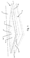
- Fig. 1 shows an embodiment of a flat-roof skylight window 1 according to the first aspect of the invention mounted in a flat roof 2 and comprising a weather shield 3 according to the second aspect of the invention.
- the skylight window 1 comprises a window portion 1 a that is visible in Fig. 1 behind a weather shield pane 6, specifically two side sash members of four side sash members of a window sash 4a of the window portion 1 a are visible through the pane 6.
- the window portion 1 a also comprises a frame 4b with four side frame members of which two are visible in Fig. 1 , each side frame member being positioned along and at an outside of a respective one of the four side sash members.
- the window portion 1 a also comprises an insulating windowpane 1 b mounted in the window sash 4a beneath the weather shield pane 6.
- the window portion 1 a may be in the form of the skylight window (i.e. the part of the structure positioned beneath the weather shield) shown and explained in relation to Figs 1 and 2 of WO 2009/080026 A , the weather shield 3 of the skylight window 1 according to the embodiments shown in the drawings replacing the weather shield of Figs 1 and 2 of WO 2009/080026 A .
- the window portion 1a does not comprise a window sash, but only a window frame, and the windowpane is mounted in the window frame.
- the weather shield 3 is provided as a unitary structure, which is separate from the window portion 1 a.
- the weather shield 3 is mounted on the window portion 1 a for covering and weather protecting the window portion 1 a in a mounted state of the skylight window 1.
- the weather shield pane 6 is curved outwardly, i.e. upwardly in Fig. 1 , in relation to the window portion 1 a, see further below.
- the weather shield pane 6 is a transparent windowpane of hardened glass.
- the weather shield 3 and details thereof are shown in more detail in Figs 2 to 8 .
- the weather shield pane 6 comprises two opposed substantially straight peripheral edges 6a, 6b and two opposed curved peripheral edges 6c and 6d.
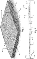
- the weather shield pane 6 further comprises a curved bottom surface 7 facing the window portion 1 a and having four bottom corners 7a, 7b, 7c and a further bottom corner not visible in the views of the figures, these four corners being positioned in an imaginary bottom plane P1, see Fig. 3 . These bottom corners are the bottom points of the corners where the respective edges 6a to 6d meet.
- the pane 6 further comprises an opposed, curved top surface 8, the two surfaces 7 and 8 having essentially the same shape and curvature.
- the curvature of the bottom surface 7 follows the following geometric definitions according to the first aspect of the invention:
- an apex line or peak line X extends horizontally, i.e. in a depth direction of Fig. 3 , between the two curved edges 6c and 6d where the bottom surface 7 has the largest distance to the bottom plane P1.
- a connecting line L1 see Fig. 3 , connects the bottom corner 7a with the bottom corner not visible in the figures, the connecting line L1 extending substantially in parallel to the apex line X, i.e. in a depth direction in Fig. 3 .
- the apex line X and the connecting line L1 are positioned in an imaginary inclination plane P2, also shown in Fig. 3 .
- the planes P1 and P2 intersect in the line L1.
- the weather shield pane 6 is shaped substantially as a cylinder shell segment curving outwardly in relation to the window portion 1a. Specifically, each of the two surfaces 7, 8 have the shape of a cylinder shell segment.
- the cylinder shell segment is a circular cylinder shell segment so that the curved peripheral edges 6c, 6d of the weather shield pane 6 substantially follow a circular arc, see especially Fig. 3 .
- a radius of the circular cylinder shell segment is about 8.5 m.
- the curvature of the weather shield pane 6 is so that the top surface 8 of the pane 6 slopes upwardly in an entire area of this top surface 6 in top surface 8 areas on both sides of the apex line X so that no depressions and no horizontal areas exist in or at the top surface 6.
- the apex line X extends substantially horizontally in the mounted position of the skylight window 1.
- the weather shield pane 6 is substantially symmetric about the apex line X.
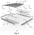
- the weather shield 3 further comprises the weather shield skirt 5 supporting the weather shield pane 6 and extending along the four side edges 6a to 6d of the weather shield pane 6 to seal the window portion 1 a from the surroundings and/or avoid or lessen entrance of water and/or dirt into the window portion 1a.
- the weather shield skirt 5 comprises four side skirt members 5a, 5b, 5c and 5d that are positioned to substantially form a square when seen from above.
- the skirt members 5a, 5b, 5c and 5d are assembled to form the skirt 5 in an essentially known manner by use of corner keys 5e, see Fig. 4 .
- the weather shield skirt 5 is attached to the window portion 1 a in a not shown manner, specifically to the window frame 4a and/or to the window sash 4b, so as to place the weather shield pane 6 in position above the window portion 1 a.
- a person skilled in the art will be able to devise how to accomplish this.
- the side skirt members 5a to 5d extend substantially at right angles to the plane P1, each supporting a respective one of the peripheral side edges 6a to 6d of the pane 6 so that the weather shield pane 6 is embedded and mounted in the weather shield skirt 5.
- the weather shield pane 6 is positioned with its two straight peripheral side edges 6a, 6b substantially in parallel with the two side skirt members 5c, 5d, respectively, and with the two curved peripheral side edges 6c, 6d extending along or adjacent to the other two side skirt members 5a, 5b, respectively.
- the weather shield pane 6 has a substantially constant thickness along an entire pane area, i. e. a distance between the top surface 8 and the bottom surface 7 is substantially constant over an entire area of the weather shield pane 6, see Fig. 3 .
- This thickness is about 5 mm.
- An entire surface area of the top and bottom surfaces 7, 8, respectively, is about 2 m 2 , a length and width of the pane 6 being about 1.4 m, respectively.
- the insulating windowpane 1b of the window portion 1a comprises three layers of glazing mounted in the window frame 4b and with an inert gas between them.
- the window frame 4b and window sash 4a side members are respectively positioned substantially in a square.
- the window portion glazing is a so-called IGU (Insulating Glazing Unit).
- the skylight window 1 may be made to be openable, which may be achieved in the following manner:
- the window portion 1a is in itself openable, whereby the window sash 4a can open in relation to the window frame 4b.
- the weather shield 3 is attached to the window sash 4a of the window portion 1 a so that the window sash 4a and the weather shield 3 move together and open in relation to the window frame 4b. This is achieved by the window sash 4a rotating along one of the window frame side members during opening of the skylight window 1, the window sash 4a being rotatably attached to the window frame 4b along the said window frame side member.
- the weather shield 3 is mounted on the window portion 1 a in such a manner that the weather shield 3 follows the window sash 4a in an opening movement by the window sash 4a in relation to the window frame 4b.
- a chain drive system may be provided to drive or achieve the opening and closing movements.
- the apex line X has a distance to the plane P1 of about 10 to 80 mm, preferably 15 to 40 mm, follows a transverse centre line of the weather shield pane 6 and extends in parallel with the straight edges 6a, 6b of the weather shield pane 6.
- the apex line X extends at a length substantially identical to a length of each of the straight edges 6a, 6b of the weather shield pane 6.
- the height from the plane P1 to the top of the weather shield pane 6 surface 8 is between 1-4% of a total pane 6 width when this height is measured at the apex line X.
- the skylight window 1 is mounted in the flat roof 2 so that the plane P1 and the windowpane 1b are positioned substantially horizontally.
- the weather shield glass pane 6 has been moulded or cast to assume its final, curved shape.
- the weather shield pane 6 is coated on the top surface 8 thereof with a coating which enhances the dewatering properties of the top surface by lowering the surface tension properties.
- the coating is a self-clean and hydrophobic coating that contains titanium dioxide.
- a length and width of an imaginary rectangle defined by the four bottom corners, including the bottom corners 7a, 7b and 7c, of the weather shield pane 6 are larger than a corresponding outer length and width, respectively, of the window frame 4b of the window portion 1 a, see Fig. 1 .
- the side skirt members 5c to 5d are best seen in Fig. 4 .
- the side skirt members 5a and 5b are mirrored versions of each other, and the side skirt members 5c and 5d are mirrored versions of each other.
- the side skirt member 5a comprises a base portion 10 that extends in parallel with an opposed, mirrored base portion 11 of the opposed side skirt member 5b.
- the base portions 5a, 5b extend substantially along a full length of the two curved edges 6c and 6d, respectively.
- the side skirt member 5a is shown in more detail in Figs 5a to 7 , to which reference is made in the following.
- the side skirt member 5a comprises a first supporting leg 12, the corresponding, mirrored supporting leg 13 of the opposed side skirt member 5b being visible in Fig. 4 .
- the first supporting leg 12 extends in an inward direction from and at an angle to an inner surface 14 of the base portion 10, which inner surface 14 faces the opposed side skirt member 5d.
- the curved edge 6c of the weather shield pane 6 rests on a supporting surface 15 of the first supporting leg 12, see Figs 6a and 7 .
- the supporting surface 15 extends along the curved edge 6c in a curve substantially corresponding to the curve along which the curved edge 6c extends.
- the supporting surface 15 of the first supporting leg 12 is an upper surface or upper support area of some size shaped according to a peripheral area of the curved bottom surface 7 of the weather shield pane 6 at the edge 6c thereof.
- the supporting surface 15 is in indirect contact with the weather shield pane 6 as shown in Fig. 6a so as to spread part of the gravity load of the pane 6 on the surface area 15 and thereby reduce forces on the pane 6 itself as well as on the first supporting leg 12.
- a flexible adhesive sealing and cushioning element 50 is provided between the supporting surface 15 and the bottom surface 7 of the pane 6, see Fig. 6a , this element 50 extending along substantially an entire length of the edge 6c. See the description of Figs 10a and 10b below regarding the details of the element 50, which may comprise one or more of the elements 46, 47 and 49 of Figs 10a and 10b .
- the inward direction in which the first supporting leg 12 extends is a direction from the base portion 10 towards an interior spacing 16 enclosed by the weather shield pane 6, the skirt 5 and the window portion 1 a. It is also a direction towards the opposed base portion 11.
- the base portions 10, 11 each extend substantially in a plane. However, at a lower part of the base portions 10, 11, projections are included for providing sealing between the skirt 5 and the window frame 4b and/or the window sash 4a. These projections are of types known to a person skilled in the art and will not be described in detail.
- the two planes in which the base portions 10, 11 generally extend are substantially parallel with each other and are substantially vertical.
- the first supporting leg 12 is attached to the base portion 10 at an inner end and at a distance from a top end 17 thereof.
- the supporting surface 15 of the supporting leg 12 extends over substantially a full length of the curved edge 6c so that substantially an entire length of the curved edge 6c is supported on the supporting surface 15.
- the first supporting leg 12 comprises a plane tongue or lower portion 12a and an adapter element 12b, the adapter element 12b comprising the supporting surface 15 and being arranged between the lower portion 12a and the (bottom surface 7 area at the) curved edge 6c.
- the adapter element 12b adapts the plane lower portion 12a to correspond to the curved shape of the (bottom surface 7 area at the) curved edge 6c.
- the lower portion 12a extends upwardly at an angle slightly different from a right angle to the base portion 10, specifically the inner surface 14 thereof. This angle may generally be 1 to 20 degrees or 2 to 7 degrees.
- the lower portion 12a is attached to and integral with the base portion 10 so that the lower portion 12a and the base portion 10 forms one unitary member manufactured as an integral extruded aluminium profile.
- the base portions and lower portions or first supporting legs of the other skirt members 5b, 5c and 5d are similar unitary profiles.
- the unitary profiles are in the present embodiment and may also in other embodiments generally be extruded aluminium profiles that may subsequently be punched in shape, especially along the top ends, including top end 17, of the base portions.
- the adapter element 12b is and may also generally be an element separate from the base portion 10.
- the adapter element 12b is substantially crescent-shaped, see Fig. 5a , with a substantially straight bottom surface, which abuts an upper surface of the lower portion 12a, and a curved upper surface constituting the supporting surface 15.
- the adapter element 12b may be attached to the base portion 10 and/or to the lower portion 12a using attachment members (not shown), e.g. clips, screws or bolts.
- the adapter element 12b, base portion 10 and/or the lower portion 12a may accordingly comprise attachment holes (not shown) for insertion and attachment of the attachment members.
- the attachment members may form part of or be attached to the adapter element and may comprise a snap-lock system for snap-locking the attachment members in the attachment holes.
- the adapter element 12b is manufactured from a resilient, flexible plastics material, specifically cut/punched or moulded plastic (ASA). Together with the lower portion 12a a spring effect is thus provided, which improves absorption of the forces from the pane 6 on the supporting leg 12.
- ASA cut/punched or moulded plastic
- the side skirt member 5c is shown in more detail in Fig. 8 , the reference numbers of similar or like elements of Fig. 8 being the reference numbers of Figs 5a to 7 multiplied with 10.
- the side skirt member 5d is a mirrored version of the side skirt member 5c and functions in the same manner.
- the side skirt member 5c comprises, similar to the side skirt member 5a, a base portion 100 and a first supporting leg 120 similar to the base portion 10 and the first supporting leg 12 of the side skirt member 5a, the side skirt member 5c similarly supporting the (bottom surface area at the) straight edge 6b of the weather shield pane 6.
- the supporting leg 120 extends, similar to the supporting leg 12, substantially in a plane and at a slight angle in the inward direction and from an inner surface 140 of the base portion 100 so as to fit the slightly angled bottom surface at the straight edge 6b of the pane 6 (this bottom surface being substantially straight at this small peripheral area of the pane 6 bottom surface 7).
- the (bottom surface at the) straight edge 6b of the weather shield pane 6 rests on an upper supporting surface 150 of the first supporting leg 120. No adapter element like the adapter element 12b is needed here since the pane 6 does not curve along its straight edges 6a, 6b.
- all side skirt members 5a to 5d can thus be manufactured from one side skirt member starting element or blank.
- the lower portion 12a of the side skirt member 5a can thus be of the same shape and size as the supporting leg 120 of the side skirt member 5c.
- the side skirt member 5c only subsequently needs to be punched at its top end 170 to correspond to the straight edge 6b of the pane 6.
- the side skirt member 5a is correspondingly punched at its top end 17 to correspond to the curved edge 6c of the pane 6, and the adapter element 12b is attached to the lower portion 12a of the supporting leg 12 to form part of the supporting leg 12.
- the adapter element 12b may be used to adapt the supporting leg 120 into the supporting leg 12.
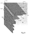
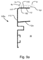
- Figs 9 and 10 show an alternative embodiment of the side skirt member 5a of Figs 5a and 5b , denoted 105a.
- Fig. 9 100 has been added to the reference numbers for the side skirt member 5a for identical elements or elements of the same function compared to the side skirt member 5a. Only differences from the side skirt member 5a will be described in the following.
- a first supporting leg 112 is constituted by a bent portion bent inwardly from the material of a base portion 110 of the side skirt member 105a and thus extends from a top end 117 of the base portion 110.
- the curved edge 6c is supported on an upper supporting surface 115 of the supporting leg 112 that follows the curvature of the pane 6 at the curved edge 6c.
- the adapter element 12b as described above need not be present in this embodiment.
- an adhesive tape 150 and a cushioning silicone sealing element 151 are provided between the surface 115 and the bottom surface 7 of the pane 6.
- the supporting leg 112 is plate-shaped and shaped to follow the curvature of the edge 6c along the entire length of the edge 6c of the pane 6.
- This embodiment is especially advantageous with the relatively small curvature of the pane 6 since with larger curvatures, deformations in the side skirt member 105a during bending may be so large that it would be too difficult to maintain the shape of the base portion 110 or the supporting leg 112 during bending.
- the side skirt member 105a comprises a base portion 112a (not of the supporting leg in this embodiment) that may be used as the supporting leg 12 for the side skirt member 5c so that all side skirt members 5a to 5d may be manufactured from the same blank as explained above.
- edges 6a to 6d of the pane 6 may be rounded as the edge 6a shown in Figs 9 and 9a or straight as the edge 6a shown in Figs 7 and 8 .
- the weather shield pane 6 surface 8 defines the skylight window top surface, and substantially no parts such as skirt members obstruct or cover the surface 8.
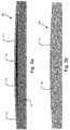
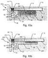
- Fig. 10a shows an alternative embodiment 105c of the second side skirt member 5c of Fig. 8 .
- 100 has been added to the reference numbers used for the side skirt member 5c for identical elements or elements of the same function compared to the side skirt member 5c. Only differences from the side skirt member 5c will be described in the following.
- the weather shield pane 6 is supported on and in indirect contact with a first supporting leg 220 of the side skirt member 105c.
- a gutter recess 40 is provided in the supporting leg 220 such as to act as a gutter collecting water potentially entering between the weather shield pane 6 and a base portion 200.
- the supporting leg 220 comprises an upward step 41 at a distance from the base portion 200 so that the gutter recess 40 extends between the upward step 41 and an inner surface 240 of the base portion 200, this upward step 41 extending substantially in parallel to the base portion 200.
- the gutter recess 40 comprises a bottom surface, which is a part of an upper surface of the supporting leg 220.
- the step 41 forms two substantially right angles of the supporting leg 220.
- the supporting leg 220 At a right end of the supporting leg 220 facing away from the base portion 200, the supporting leg 220 comprises a resting portion 48 on which the weather shield pane 6 indirectly rests.
- This resting portion 48 is provided so that the gutter recess 40 is located between the base portion 200 and the resting portion 48.
- the resting portion 48 has a substantially linear and plane profile, and a supporting surface 250 is provided as an upper surface of the resting portion 48.
- the skirt member 105c also comprises a second supporting leg 42, which extends integrally with, inwardly from and at a substantially right angle to an inner surface 240 of the base portion 200.
- An elastic sealing element in the form of a silicone joint or seam 44 is positioned to seal a gap between the pane 6 and the inner surface 240 of the base portion 200, the supporting leg 42 supporting the sealing element 44 via a support element 45.
- the support element 45 is of a resilient plastics material.
- the supporting leg 42 supports the sealing element 44 to keep it in place between the pane 6 and the base portion 200.
- the members 44 and 45 are oblong and extend to cover an oblong recess or gap between the pane 6 and the base portion 200.
- This recess and the elements 44 and 45 extend substantially along an entire length of the curved edge 6b of the pane 6. If similar side skirt members are used along the other edges of the pane 6, a similar recess may extend along those edges, and a similar sealing element may extent in those recesses as well.
- the supporting leg 42 is positioned above the supporting leg 220 between the top end 170 of the base portion 200 and the supporting leg 220.
- the supporting leg 42 is positioned at a distance from the top end 170 and the supporting leg 220.
- An adhesive tape 46 is provided between the pane 6 and the supporting surface 250 to adhere the pane 6 to the side skirt member 105c.
- a silicone member 47 is positioned to provide cushioning and sealing between the pane 6 and the supporting surface 250.
- Fig. 10b shows an embodiment similar to that shown in Fig. 10a , but which has been slightly modified in that the elements 46 and 47 have been replaced by a thinner cushioning and adhesive tape 49, which may be of the type 3M® VHP, and the resting portion 48 is shifted slightly upwards so that it lies in the same plane as the supporting leg 42.
- a thinner cushioning and adhesive tape 49 which may be of the type 3M® VHP
- a not shown alternative embodiment of the side skirt member 5a shown in Figs 5a to 7 is modified to a structure similar to the structure of the side skirt member 105c as shown in Fig. 10a or Fig. 10b .
- a similar starting element or blank i.e. an aluminium profile
- similar to the side skirt member 205c forms a base portion and a supporting leg of the modified side skirt member 5a.
- the base portion 200 of the side skirt member 105c at its top end 170 is punched to substantially follow the straight edge 6b of the pane 6, similar to in the embodiment of Figs 5a to 7 the base portion of the modified side skirt member 5a at its top end is punched to be curved to substantially follow the curved edge 6c of the pane 6.
- the modified design of the side skirt member 5a also comprises a gutter recess, a step and a resting portion similar to the gutter recess 40, step 41 and resting portion 48, respectively, as shown in Fig. 10a or Fig. 10b .
- an adapter element similar to the adapter element 12b is provided on an upper surface of the resting portion so as to similarly provide a curved supporting surface similar to the supporting surface 15.
- the members 46, 47 and 49 of Figs 10a and 10b may potentially be disposed of, or one or more of these members may be positioned between the supporting surface and the bottom surface of the pane 6.
- a similarly shaped, but somewhat thinner adapter element may be positioned on an upper surface of a second supporting leg of the modified design of the side skirt member 5a, which corresponds to the supporting leg 42, so as to similarly provide a curved upper supporting surface of the second supporting leg that follows the curved side edge 6c.
- one or both of its supporting legs are modified so that one or both by themselves, i.e. without the use of an adapter element, are curved so as to follow the curved side edge 6c of the pane 6.
- Fig. 11 shows an alternative embodiment of the weather shield 3 of Figs 1 to 8 .
- 200 has been added to the reference signs of the embodiment of the weather shield shown in Fig. 11 , which is thus denoted 203 and comprises a weather shield skirt 205.
- the skirt 205 in this embodiment is a unitary structure of side skirt members 205a to 205d, which are integrally reaction injection moulded (RIM) from a plastics material, specifically PUR (polyurethane), around the pane 6 so as fit very precisely with the edges of the pane 6.
- RIM integrally reaction injection moulded
- PUR polyurethane
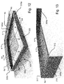
- Figs 12 and 13 show a slightly modified embodiment of the weather shield 205 of Fig. 11 .
- Another 100 has been added to the reference signs of this embodiment of the weather shield, which is thus denoted 303 and comprises a weather shield skirt 305. Only differences compared to the embodiment of Fig. 11 will be described in the following.
- the skirt 305 is premoulded, i.e. moulded before insertion or mounting of the pane 6 along the arrows of Fig. 12 .
- the side skirt member 305b comprises a supporting leg 312, which is similar to the supporting leg 12 in Figs 5a to 7 , but positioned at a distance from a top edge 317 of a base portion 310.
- the opposing side skirt member 305a has a mirrored structure of the side skirt member 305b. Similar to in the previous embodiments, the side skirt members 305c and 305d comprise straight supporting legs, each corresponding to the curved supporting leg 312.
- the embodiment of Fig. 11 may comprise supporting legs similar to the supporting legs of the embodiment of Figs 12 and 13 .
- the side skirt members of Figs 11 to 13 may generally comprise elements similar to in any one of the previous embodiments, including a second supporting leg and a gutter recess that may have identical functions.
- a height, i.e. in an up-down direction of Fig. 1 or 3 , of any one of the side skirt members described above may generally be 50 to 200 mm, preferably 60 to 150 mm, more preferred 80 to 100 mm.
Landscapes
- Engineering & Computer Science (AREA)
- Architecture (AREA)
- Civil Engineering (AREA)
- Structural Engineering (AREA)
- Building Environments (AREA)
- Roof Covering Using Slabs Or Stiff Sheets (AREA)
- Securing Of Glass Panes Or The Like (AREA)
Abstract
Description
- The present invention relates in a first aspect to a flat-roof skylight window for being positioned substantially horizontally in a flat roof, the skylight window comprising a window portion and a weather shield, which is mounted on the window portion to cover and weather protect the window portion in a mounted state of the skylight window.
- The invention relates in a second aspect to a weather shield for use in the skylight window according to the first aspect of the invention.
- There is often a desire to position one or more skylight windows in a flat roof of a building, i.e. where the roof has substantially no inclination or only a very small inclination. This may give rise to a variety of challenges.
- If a skylight window of a type, which is used in inclining roofs and with a flat, insulating windowpane, is positioned in a flat roof, gravity will pull the pane downwards so that the pane will curve slightly downwards towards a centre thereof with a lowest point typically at a centre of the pane. If no weather shield is present, rain water will typically be collected at and near the lowest point to create, for example, a pool of water. Typically, also dirt will accumulate on the windowpane, especially at or near the centre thereof. This may limit the view through the windowpane from inside the building as the water and dirt disturb the visibility through the windowpane. Further, the pane may become a structural weak point, especially also with regards to snow loads.
- One way to improve dewatering and prevent accumulation of snow on the windowpane is to angle the skylight window and the windowpane to provide a slope similar to a window positioned in an angled roof. This may be done by raising one side member of a frame and/or sash of the window so that the windowpane is angled with respect to horizontal. However, by angling the windowpane, one side member of the frame and/or sash will be higher than the opposing side, and the two side members at the sides will also slope. Hereby, the raised sash member and/or frame member as well as the sloping side members connected thereto may disturb the view through the windowpane compared to if the window were positioned horizontally. Also, raising one of the side members requires more sash and/or frame material, is cumbersome to construct and mount in the roof, and may create an undesired aesthetical appearance of the building since the windows will be more visible from the outside and look differently when they project upwards in a sloping manner from the flat roof.
-
PL 401880 - In some alternative prior art solutions, a flat-roof skylight window positioned horizontally comprises a transparent weather shield, usually of a cast plastics material such as acrylic or polycarbonate and positioned above a window portion that comprises the frame and/or sash as well as the windowpane. The weather shield typically covers an entire top surface and has a curved dome-shaped top surface so that collection of rain water, snow and the like on the top surface is lessened since it may run along sloped sides of the weather shield and onto the roof. The weather shield typically covers the entire window portion and may generally protect the window portion and the interior of the building from a range of weather loads or influences, including wind and precipitation, such as rain, snow, hail, etc. The weather shield may also provide supplementary insulation of the skylight window, i.e. of the window portion and the weather shield. The weather shield is typically attached to a frame and/or a sash of the window portion.
- Use of a weather shield as described may have several drawbacks. Typically, the shape of the weather shield, due to its curvature or shape, distorts light and thus the view through the window and/or allows significantly less light to pass through the window. Some prior art weather shields comprise a skirt, which extends on all sides of the weather shield to cover the sash and/or frame of the window portion, this skirt often getting in the way of opening the window by hitting parts of the window portion or the roof.
- The shape and size of the prior art weather shields also often result in large wind loads on the weather shield and thus the window portion and/or the roof, making it necessary to dimension strength and stiffness of the weather shield, window portion and roof accordingly.
- An example of a flat-roof skylight window with a weather shield is disclosed in applicant's
WO 2009/080026 A relating to a flat-roof skylight window with a dome-shaped weather shield covering an insulating window portion, the specification thereof being incorporated herein in its entirety. -
US 8,375,657 discloses an insulated glazing unit in which one of the glazing layers of a pane thereof is curved. -
WO 08085072 A - On this background it is an object of the first aspect of the present invention to provide a flat-roof skylight window according to the introduction in which it is possible to reduce assembly of water and dirt on an upper or outer surface of the weather shield. Another object is to reduce distortion of the view through the skylight window. Another object is to provide a skylight window, which can be made openable. Another object is to balance a precipitation dispersing effect with wind load characteristics of a skylight window.
- In the first aspect of the invention, these and further objects are met by a flat-roof skylight window for being positioned substantially horizontally in a flat roof, the skylight window comprising
a window portion with an optional window sash, a window frame and an insulating windowpane mounted in the window sash or window frame, and
a weather shield, which is mounted on the window portion for covering and weather protecting the window portion in a mounted state of the skylight window,
wherein the weather shield comprises a weather shield pane, which is curved outwardly in relation to the window portion,
the weather shield pane comprising two opposed substantially straight peripheral edges and two opposed curved peripheral edges,
the weather shield pane further comprising a curved bottom surface facing the window portion and having four bottom corners positioned in an imaginary bottom plane P1,
an apex line or peak line X extending between said two curved edges where the bottom surface of the weather shield pane has a largest distance to the bottom plane P1,
a connecting line L1 connecting two of said bottom corners, the connecting line L1 extending substantially in parallel to the apex line X,
the apex line X and the connecting line L1 being positioned in an imaginary inclination plane P2,
wherein an angle α between the bottom plane P1 and the inclination plane P2 is between 1 and 10 degrees. - In the present specification, the term "curved" may be understood as having a non-linear shape, potentially without sudden or sequential steps.
- The weather shield may be provided separately from the window portion.
- The weather shield may be substantially symmetric about the apex line X.
- By providing a flat-roof skylight window with a weather shield of the type mentioned above, water masses larger than droplets will typically run off the weather shield pane so that pools of water will not collect on a top surface of the weather shield pane. The outward curvature of the weather shield pane may increase the moment of inertia of the weather shield pane, whereby the force of gravity on the weather shield pane will not pull a centre of the weather shield pane lower than the edges of the weather shield pane so that rain water falling on the weather shield pane will not create a pool at the centre of the weather shield pane. Therefore, pools of water and to a large degree assembly of dirt on the top surface of the weather shield pane may be avoided. For some glass type surfaces, individual droplets do not run off unless an angle of an inclined top surface thereof is above 20 degrees or so. However, assembly of pools of water and dirt at an area of a top surface of the weather shield pane is avoided or largely avoided with the skylight window according to the invention. At the same time, the inclination of the weather shield pane is small enough to affect or distort the view through the weather shield pane and thus through the skylight window only to a small degree, typically small enough to not be noticeable to persons within a building in the roof of which the skylight window is mounted. The inventor of the present invention has thus found that, surprisingly, acceptable water dispersing, minimized distortion of the view through the skylight window and minimized use of weather shield and window portion material may be achieved with the skylight window according to the invention.
- Size and weight of a weather shield of the skylight window according to the invention may be made relatively small compared to the weather shields of the prior art, making it easier to open and saving on material. Also, due to the minimal extent that the weather shield pane projects upwardly in the mounted position of the skylight window, wind loads on the weather shield will be smaller and, thus, strength and stiffness requirements in relation to all parts of the skylight window as well as the roof in which it is potentially mounted will be reduced.
- The inventor has found that due to its curvature as defined above, the weather shield pane will have a structural load capacity able to withstand larger loads both from wind and snow. Additionally, the weather shield pane can be relatively cheaply manufactured, even from stiffer and harder materials, such as glass or hardened glass, which may further increase the structural integrity of the skylight window and improve view through the window while achieving the above advantages.
- Preferably, the curvature of the weather shield pane may be so that in an entire area of a top surface of the weather shield pane, the top surface slopes upwardly, specifically in two top surface areas on both sides of the apex line, so that no depressions, and preferably also no horizontal areas, exist in or at the top surface. But note that the apex line itself may extend substantially horizontally in the mounted position of the skylight window. The apex line may generally extend linearly.
- The weather shield of the skylight window according to the invention may further comprise a weather shield skirt supporting the weather shield pane and extending at one or more side edges of the weather shield pane to further seal the window portion from the surroundings and/or avoid or lessen entrance of water and/or dirt into the window portion. One or more sealing elements may be located between the skirt and the weather shield pane. The weather shield skirt may comprise four side skirt members, specifically two pairs of opposed side skirt members, and these four side skirt members may be positioned to substantially form a rectangle. The side skirt members may each be substantially plane and/or extend substantially linearly and/or may take the form of profiled skirt members, potentially comprising or consisting of aluminium. The weather shield skirt may be attached to the window portion, specifically to the window frame or the window sash of the window portion so as to place the weather shield pane in position above the window portion.
- The plane P1 may be substantially parallel to a plane of the window portion windowpane. The skirt members may extend substantially at respective right angles to the plane P1. One or more of the side skirt members may support a respective peripheral edge, i.e. a side edge, of the weather shield pane. The weather shield pane may thus comprise four corresponding side edges.
- The weather shield pane may be embedded or mounted in and/or attached to the weather shield skirt. A cushioning member and/or an adhesive, such as glue, or an adhesive member, such as an adhesive tape, may be provided between edges of the weather shield pane and supporting surfaces of the weather shield skirt. Additionally or alternatively, the weather shield pane may be attached to the weather shield skirt by clamping or other mechanical means. The weather shield side skirt members may each be an aluminium profile. The weather shield pane may be positioned with its two straight peripheral edges substantially parallel with two opposed side skirt members and with its two curved peripheral edges extending along or adjacent to other two opposed side skirt members.
- The weather shield pane preferably has a substantially constant thickness along an entire pane area, a distance between a top surface and the bottom surface of the weather shield pane potentially being substantially constant over an entire area of the weather shield pane. This further prevents distortion of the view through the skylight window. This thickness may be 3 mm to 7 mm, preferably 4 mm to 6 mm. An entire upper or lower surface area of the weather shield pane may be 0.5 m2 to 10 m2, preferably 0.7 to 6 m2, more preferred 0.8 to 4 m2.
- The shape of the weather shield pane in a cross-sectional plane can be concave, parabolic, cylindrical or elliptic cylindrical. The curved edges of the weather shield pane may substantially follow an arc, e.g. an elliptic or circular arc, and the pane may follow an arc, e.g. an elliptic or circular arc, in a cross section taken along a cross-sectional plane extending substantially at a right angle to a plane through which the apex line X extends and at a right angle to the plane P1.
- The weather shield pane may comprise only one single layer of glazing. The insulating windowpane of the window portion may comprise at least two layers, for example two or three layers, of glazing mounted in the window sash or the window frame, potentially with an inert gas between them. The window frame and or the window sash may have four side members that may be positioned substantially rectangularly. A glazing of the window portion including the windowpane may take the form of a so-called IGU (Insulating Glazing Unit).
- The skylight window according to the invention may be openable. This may be achieved with a window portion that in itself is openable, whereby the window sash may open in relation to the window frame. The weather shield may be attached to the window sash of the window portion so that the window sash and the weather shield move and/or rotate together to open in relation to the window frame. This may be achieved by the window sash rotating along one of the window frame side members during opening of the skylight window, one side sash member being rotatably attached to the window frame along the said window frame side member. The weather shield may be mounted on the window portion in such a manner that the weather shield follows the window sash in an opening movement by the window sash in relation to the window frame. A chain drive system may be provided to achieve the opening and closing movements. The weather shield according to the second aspect of the present invention makes it possible to design the skylight window so that it can be opened more easily in the described manner, see further below.
- The weather shield pane is preferably a windowpane and/or preferably is transparent and/or translucent, i.e. allows light to pass through it. Preferably, at least 50, 60, 70, 80 or 90 percent of visible light is allowed to pass through the weather shield pane.
- The angle α between the bottom plane P1 and the inclination plane P2 is preferably between 1 and 8 degrees, more preferred 1 and 6 degrees, more preferred 2 and 6 degrees, more preferred 2 and 5 degrees, more preferred 2 and 4 degrees, more preferred between 2.5 and 3.5 degrees, most preferred about 3 degrees.
- The apex line may have a distance to the plane P1 of 5 to 100 mm, preferably 10 to 80 mm, more preferred 15 to 40 mm. Additionally or alternatively, the apex line may follow a centre line, which may be linear, of the weather shield pane. Additionally or alternatively, the apex line may extend in parallel with one or both of the straight edges of the weather shield pane. Additionally or alternatively, the apex line may extend at a length substantially identical to a length of one or both of the straight edges of the weather shield pane.
- The weather shield pane, the window sash and/or the window frame may have an overall rectangular or quadratic shape.
- The skylight window according to the invention may be mounted in a flat roof so that the plane P1 is substantially horizontal and or the windowpane of the window portion is substantially horizontal. The angle of the plane P1 and/or of the windowpane of the window portion to horizontal in the mounted state may be 0 to 5 degrees, 0 to 4 degrees, 0 to 3 degrees, 0 to 2 degrees or 0 to 1 degrees.
- The window portion according to the first aspect of the present invention may be that of the skylight window (i.e. the part of the structure positioned beneath the weather shield) shown and explained in relation to
Figs 1 and2 of the above-mentionedWO 2009/080026 A , the weather shield of the skylight window according to the present invention replacing the weather shield ofFigs 1 and2 ofWO 2009/080026 A . Attachment of a weather shield skirt to the weather shield sash may be accomplished in a similar manner. - In an embodiment of the skylight window according to the invention, the weather shield pane is shaped substantially as a cylinder shell segment curving outwardly in relation to the window portion.
- The cylinder shell segment may be a circular cylinder shell segment so that the curved peripheral edges of the weather shield pane substantially follow a circular arc. A radius of the circular cylinder shell segment may be 2.5 to 15 m, 5 to 12 m, 7 to 10 m or 7.5 or 8.5 m.
- The cylinder shell segment need not necessarily be of a circular cylinder, but may be of other cylinder shapes. It is preferred that the cylinder shell segment curves outwardly along an entire curve of the cylinder shell segment so that precipitation is not collected in pockets of the surface of the weather shield pane, see also above.
- By providing a weather shield pane of this design, the structural benefits of cylinder shell shaped structures are made use of in the weather shield pane, e.g. the moment of inertia of the weather shield pane is increased, thus improving strength and stiffness of the flat-roof skylight window.
- Alternatively, the curvature of the weather shield pane is substantially parabolic. In any case, it is preferred that the curvature of the weather shield pane does not comprise any sequential steps, i.e. immediate or sudden changes of curvature that may disturb the view through it.
- In an alternative to this embodiment, a substantially parabolic weather shield pane is provided. Hereby, manufacturing of the weather shield pane may be simplified as a flat pane that can simply be fixed at two opposed straight side edges and a force applied at the centre, whereby the pane will curve outwardly. This is especially a structural possibility due to the relatively low angle α. Thus, manufacturing costs can be reduced.
- In another embodiment the weather shield pane is made of or comprises glass, preferably hardened glass. A weather shield glass pane may be moulded or cast to assume its final, curved shape or it may be cast first, e.g. in a substantially plane shape, and then subsequently deformed to assume its curved shape.
- By using glass compared to plastic, which is traditionally used in weather shields in flat-roof skylight windows, the weather shield becomes more wear resistant, as glass is less prone to scratching, denting and the like, and because glass has typically better structural characteristics, such as strength, hardness and stiffness. Scratches and dents will increase the roughness of the weather shield pane surface so that water will more likely be retained on the surface of the weather shield if the weather shield pane is made of plastic. Comparably, especially the dome-shaped plastic weather shields of the prior art would be expensive to manufacture in glass.
- In another embodiment the weather shield pane is coated on a top surface thereof with a coating which enhances the dewatering properties of the top surface by lowering the surface tension properties, lowering the surface roughness or affecting other physical properties of the top surface. The coating may be a self-clean coating and/or a hydrophobic coating and/or may contain titanium dioxide.
- In another embodiment a length and width of an imaginary rectangle defined by the four bottom corners of the weather shield pane are larger than a corresponding length and width, respectively, of the window frame.
- By extending the weather shield pane farther out than the window frame of the window portion of the flat-roof skylight window, water from the upper surface of the weather shield pane may be led to outside peripheral edges of the window portion while, for example, using side skirt members that extend at substantially right angles to the plane P1. Thus, the risk of water entering into the window portion or the building through the window portion is decreased.
- The second aspect of the invention provides a weather shield for being mounted on a window portion for forming a flat-roof skylight window according to any one of the above embodiments, the weather shield comprising
a weather shield pane comprising two opposed substantially straight peripheral edges and two opposed curved peripheral edges, and
a weather shield skirt supporting the weather shield pane and comprising two opposed first side skirt members, each of the first side skirt members supporting one of said curved edges, wherein each of the first side skirt members comprise a base portion, said base portions extending substantially in parallel with each other, each said base portion extending substantially along a full length of a respective one of said two curved edges,
at least one of said first side skirt members further comprising a first supporting leg, the first supporting leg extending in an inward direction from and at an angle to an inner surface of the respective base portion of said one of the first side skirt members, said inner surface facing the other of said first side skirt members, one of said curved edges of the weather shield pane resting on a supporting surface of said first supporting leg,
wherein said supporting surface extends along said one of the curved edges in a curve substantially corresponding to a curve along which said curved edge extends. - With the second aspect of the invention it is possible to provide superior support of a curved edge of a weather shield pane by means of the first supporting leg, the supporting surface of the first supporting leg following the curve of the weather shield pane at the respective curved edge thereof. Thus, surprisingly, a well-supported weather shield pane with a curved edge may be provided in a simple manner. The advantages of a curved weather shield pane with two curved side edges are described above in connection with the explanation of first aspect of the invention.
- The first supporting leg comprises a supporting surface, which may be an upper or top surface, i.e. an upper supporting area of some size shaped according to a curved peripheral bottom surface of the weather shield pane and in direct or indirect contact (indirect contact e.g. including presence of intermediate adhesion and/or sealing elements) with the weather shield pane so as to spread a gravity load of the pane on a larger area and thereby reduce forces on the pane itself as well as on the first supporting leg.
- Furthermore, sealing between the weather shield pane curved edge and the first side skirt member may be easily achieved. Some options will be explained below. Thus, a tight weather shield with good dewatering properties may be readily arrived at.
- The curved edge resting on the supporting surface is intended to include that a peripheral lower area or portion of a bottom surface of the weather shield pane rests on the supporting surface. The curved peripheral edges of the weather shield pane may alternatively be denoted "curved peripheral portions or areas" of the weather shield pane. These curved peripheral portions may each comprise a bottom surface area in contact with the first supporting leg(s).
- Similar to in the first aspect of the invention, the weather shield pane of the weather shield according to the second aspect of the invention may further comprise a curved bottom surface intended to face a window portion and having four bottom corners positioned in an imaginary bottom plane P1, an apex line or peak line X extending between said two curved edges where the bottom surface of the weather shield pane has the largest distance to the bottom plane P1, a connecting line L1 connecting two of said bottom corners, the connecting line L1 extending substantially in parallel to the apex line X, the apex line X and the connecting line L1 being positioned in an imaginary inclination plane P2, wherein an angle α between the bottom plane P1 and the inclination plane P2 is between 1 and 10 degrees. The angle α may be within the preferred angle intervals mentioned above. Hereby, advantages similar to those above in relation to the first aspect of the invention may be achieved.
- In the context of the second aspect of the invention, the inward direction, in which the first supporting leg extends, may be a direction from the respective base portion towards a spacing enclosed by the weather shield pane and the skirt and/or a direction towards the other of said base portions. Similarly, the inner surface of the base portion may be defined as the surface facing said interior spacing and/or the other base portion.
- One or both of the base portions of the first side skirt members may extend substantially in a plane. These two planes may be substantially parallel with each other. The base portion(s) and/or the entire skirt may incline slightly outwardly in a downward direction, i.e. in a direction towards the intended position of the window portion. Thus, water running off the pane onto the base portion or skirt may be led along an outer surface of the base portions or skirt, away from a window portion positioned beneath the weather shield and potentially onto a roof surface.
- Generally, the opposed first side skirt member may be provided as a mirrored version of the first side skirt member. The opposed first side skirt member may similarly comprise a like first supporting leg that also extends inwardly. This opposed first supporting leg may be in the form of a mirrored version of the first supporting leg, which in a similar manner supports the other curved edge of the weather shield pane.
- As previously indicated the curved edge of the weather shield resting on the supporting surface of the first supporting leg does not necessarily rule out that a member such as a sealing member or adhesive is positioned between the curved edge (specifically a surface area at the curved edge) and the supporting surface, i.e. the supporting surface is not necessarily in direct contact with the weather shield pane.
- The weather shield skirt may further comprise two second, opposed side skirt members. The first and second side skirt members may be positioned in a rectangular shape to form a rectangular or quadratic weather shield skirt. The first side skirt members may be positioned at substantially right angles to the second side skirt members.
- One or both of the second side skirt members may comprise a base portion and/or a first supporting leg similar to the base portion and first supporting leg, respectively, of the first side skirt members and supporting a respective one of the straight peripheral or side edges of the weather shield pane. These supporting legs may extend substantially in a plane so as to fit the straight edges. These supporting legs may similarly extend in an inward direction from and at an angle to an inner surface of a respective base portion of a respective of the side skirt members, one of said straight edges of the weather shield pane resting on a supporting surface of each of said supporting legs. This supporting surface may be substantially plane and/or may follow a curve of a peripheral portion of the bottom surface of the weather shield pane near its straight edges. The first supporting leg(s) of the first and/or second skirt member(s) may extend from and at a substantially right angle to the base portion.
- The first supporting leg of the first side skirt member may be attached to the respective base portion; it may be attached at a top of the respective base portion or at a distance from the top of the base portion. It may also be integral with the base portion, i.e. provided as part of a unitary first side skirt member. This may also apply to the second side skirt members.
- The weather shield pane may be embedded in and/or attached to the weather shield skirt. For this purpose, an adhesive or an adhesive member, such as glue or an adhesive tape, may be provided between one or more of the peripheral edges of the weather shield pane and the respective supporting surface(s) of the side skirt members so as to attach the weather shield pane in or to the weather shield skirt using adhesion. Alternatively, the weather shield pane may be attached to the weather shield skirt using clamping or other mechanical means.
- The weather shield side skirt members may be provided as or comprise aluminium profiles, which may be extruded, and may be in the form of unitary or integral profiles from which the respective first supporting leg (and/or second supporting leg, see below) may be bent and/or provided during potential extrusion of the profiles. This may provide for light-weight and weather resistant side skirt members which may be produced with low costs.
- In an embodiment of the weather shield according to the second aspect of the invention the supporting surface of the first supporting leg extends over at least half of a full length of said curved edge. The supporting surface of the first supporting leg may extend over at least 70 % or 90 % of a full length of said curved edge.
- The supporting surface may comprise two or more smaller supporting surface portions that may be separated in a length of the supporting surface by interruptions, such as recesses or the like, in which case the supporting surface itself can be considered to be an accumulated surface of said smaller surface portions.
- The more the leg curvature corresponds to the curved edge of the weather shield pane, the better the weather shield pane may be supported, and the less sealant and/or adhesive has to be used between the weather shield pane and the first supporting leg, and the lower the risk of water entering the inside of the weather shield may be. It is preferred that substantially an entire length of the respective curved edge is supported on the supporting surface. However, the supporting surface may extent 30 % to 100 % of a length of the respective curved edge, this interval more preferred being 50 % to 100 %, more preferred 70 % to 100 %, more preferred 80 % to 100 %, more preferred 90 % to 100 %, more preferred 95 % to 100 %, most preferred substantially 100 %.
- In another embodiment the first supporting leg comprises a lower portion and an adapter element, the adapter element comprising the supporting surface, wherein said adapter element is arranged between said lower portion and said curved edge of the weather shield pane. Hereby, the adapter element may adapt an easily manufactured first supporting leg lower portion, which may be plane, to correspond to the curved shape of the curved edge. The lower portion may be a tongue attached to or integral with the base portion.
- The adapter element may be an element separate from the remaining parts of the first side skirt member. The adapter element may be substantially crescent-shaped, potentially with a substantially straight bottom surface, which may abut an upper surface of the lower portion, and a curved upper surface constituting the supporting surface of the first supporting leg. It may be attached to the base portion and/or the lower portion using attachment members, e.g. clips, screws or bolts. The adapter element, base portion and/or lower portion may accordingly comprise attachment holes for insertion and attachment of the attachment members. The attachment members may form part of or be attached to the adapter element and may comprise a snap-lock system for snap-locking the attachment members in the attachment holes. The adapter element may be manufactured from a material, which may be resilient, flexible and/or comprise a plastics material, potentially to improve absorption of forces in the adapter element. Correspondingly, the lower portion or tongue may provide a spring effect to further improve force absorption. This may especially be achieved in case of a substantially plane plate-shaped plane lower portion, which at one longitudinally extending edge is attached to or integral with the base portion.
- In another embodiment the first supporting leg comprises a bent portion, which is bent inwardly from the material of the base portion of the side skirt member. In this embodiment the above-mentioned bent portion may be or comprise the lower portion or tongue of the supporting leg, which bent portion is bent inwardly from the material of the base portion of the side skirt member. Alternatively, the entire first supporting leg may be the entire bent portion.
- By providing a bent portion that forms or comprises the first supporting leg, such that the curved peripheral edge is supported by this, water on the surface of the weather shield pane may dewater from the weather shield pane onto an outer surface of the side skirt member.
- The bent portion of the current embodiment may be the lower portion of the previous embodiment, an adapter element of the first supporting leg also being provided as described above. However, an adapter element as described above need not be provided in the current embodiment. Instead, it may be advantageous to dispose of the adapter element and, instead, allow the bent portion of the first supporting leg to include the supporting surface on which the curved edge of the weather shield pane rests. Thus, the bent portion of the supporting leg may be plate-shaped and may be shaped to, in at least a portion of its length corresponding to the extent of the supporting surface, follow a curvature of the curved edge of the weather shield pane. (The latter may also be the case even if the adapter element of the previous embodiment is included.) This may be especially advantageous with the weather shield according to the first aspect of the present invention due to the relatively small curvature of the weather shield pane since with larger curvatures, deformations in the first side skirt member during bending of the first side skirt member may become so large that it would be too difficult to maintain the shape of the base portion and/or the bent portion during bending. With such a curved bent portion it may especially be advantageous as described above to provide one or more interruptions, such as recesses, along a length of the bent portion and/or in the lower portion of the first supporting leg since this may lessen deformations during bending.
- Generally, the first side skirt member may be provided as an overall plate-shaped member, which has been deformed so as to provide the first supporting leg or the bent portion with a curvature in a longitudinal direction, i.e. a direction extending along a length of the curved edge of the weather shield pane.
- In another embodiment a gutter recess is provided in the first supporting leg such as to act as a gutter for water potentially entering through a gap between the weather shield pane and the first side skirt member.
- By providing a gutter recess in the first supporting leg, the weather shield may protect an inside spacing of the weather shield, i.e. a window portion beneath, in case of wear of a sealing element or an adhesive element or the side skirt members themselves, resulting in water penetrating the connection between the weather shield pane and the side skirt member. In this case, water may be collected in the gutter recess and will therefore not penetrate between the weather shield pane and the side skirt member and potentially onto or into the window portion.
- In the current embodiment the first supporting leg may comprise an upward step at a distance from the base portion so that the gutter recess extends between the upward step and the base portion, this upward step potentially extending substantially in parallel to the base portion. Alternatively, the first supporting leg may at a first distance from the base portion comprise a downward step and immediately after or at a second, longer distance from the base portion comprise an upward step so that the gutter recess is formed between the two steps. Again, these steps may potentially extend substantially in parallel to the base portion.
- The gutter recess may in all cases comprise a bottom surface, which may be a part of a surface of the first supporting leg or of the above-mentioned lower portion/tongue or the above-mentioned bent portion. In the last mentioned design with two steps, the bottom surface of the gutter may be provided between the two steps. The one or two steps may be bent at substantially right angles, and further steps may be present.
- At an end of the first supporting leg facing away from the base portion, the first supporting leg may comprise a resting portion on which the weather shield pane and/or on which the above-mentioned adapter element rests. This resting portion may be provided so that the gutter recess is located between the base portion and the resting portion. The resting portion may have a substantially linear or a curved profile, and the supporting surface may be provided as an upper surface or part of an upper surface of the resting portion. The first supporting leg as such and/or the resting portion may follow the curvature of the respective curved edge of the weather shield pane, at least over a part of the length of the curved edge, and/or the above-mentioned adapter element may be provided between the resting portion and the curved edge of the weather shield pane.
- In another embodiment the side skirt member comprises a second supporting leg, the second supporting leg extending inwardly from an inner surface of said base portion, a sealing element being positioned to seal a gap between the weather shield pane and the base portion of the first side skirt member, the second supporting leg supporting the sealing element. The sealing member is preferably elastic and may be of a resilient plastics material or silicone.
- With the second supporting leg an efficient sealing between the weather shield pane and the side skirt member may be achieved. Elastic properties of the sealing element may ensure a tight connection between the weather shield pane and the base portion, thus further decreasing the risk of water entering between the weather shield pane and the first side skirt member. Furthermore, provision of a flexible sealing member may provide a cushioning between the weather shield pane and the first side skirt member. The sealing member may be oblong and/or may extend to cover a recess or gap between the weather shield pane and the base portion. This recess may extend substantially along an entire length of the respective curved edge of the weather shield pane. A similar recess may extend along the other edges of the weather shield pane, and a similar sealing element may extent in those recesses as well.
- The second supporting leg may be positioned above the first supporting leg, i.e. closer to a top end of the base portion of the first side skirt member. The second supporting leg may be positioned at a distance from the first supporting leg. The second supporting leg may be attached to or integral with the base portion, and it may be attached at the top end of the base portion or at a distance from the top end of the base portion. It is preferred that the second supporting leg is located between the said top end of the base portion and the first supporting leg.
- Similar to the first supporting leg, an adapter element as described above for the first supporting leg may be provided for the second supporting leg. This second adapter element may similarly comprise a curved upper surface, which may be a supporting surface for supporting the sealing element, and it may be substantially identical to or a mirrored version of the first adapter element. The second supporting leg may be without an adapter element and shaped in a longitudinal direction to follow a curve of the curved edge of the weather shield pane.
- Similar to the first supporting leg as described above, the opposed first side skirt member may comprise a like second supporting leg that also extends inwardly. This opposed second supporting leg may be in the form of a mirrored version of the second supporting leg having a like function at the opposed curved edge of the weather shield pane.
- If the weather shield skirt further comprises two second, opposed side skirt members positioned at straight edges of the weather shield pane, these second side skirt members may as well potentially comprise a similar second supporting leg similar to the described second supporting leg of the first side skirt member(s) and potentially extending substantially linearly. These second supporting legs of the second side skirt members may extend substantially in respective planes so as to correspond to the straight edges of the weather shield pane and may similarly extend in an inward direction from and potentially at an angle to an inner surface of a respective base portion of each of the second side skirt members.
- If adapter element(s) are provided for the first and/or second leg as described above, and the weather shield skirt further comprises two second, opposed side skirt members, all four side skirt members may be manufactured from one side skirt member starting element or blank. Thus, the adapter elements may be used to adapt the first and/or second supporting leg to the curvature of the curved edges of the weather shield pane.
- The second supporting leg may extend from and at a substantially right angle to the base portion. Alternatively, the supporting leg may extend at an angle to the base portion of 45 to 90 degrees, preferably 70 to 90 degrees.
- In another embodiment a top end of the base portion of the first side skirt member is shaped with a curvature so as to at least along a part of the top end follow a curvature of that curved edge of the weather shield pane which is supported by the first side skirt member.
- Hereby, sealing properties are enhanced and it may be made possible to provide a sealing member, such as the above-mentioned sealing member, between an area at the top end of the base portion and the respective curved edge of the weather shield pane, especially if the above-mentioned second supporting leg also follows a curve of the curved edge of the weather shield pane.
- A curvature of the top end of the base portion may follow the curvature of the curved edge of the weather shield pane along substantially an entire length of the curved edge.
- The weather shield pane may comprise a curved bottom surface with four bottom corners positioned in an imaginary bottom plane P1, and the curved top end of the first side skirt member may be provided at substantially the same level from this bottom plane as the respective curved edge of the weather shield pane, specifically at the level of a top end of this curved edge. Hereby, a sealing member may be positioned between the top end of the base portion and the curved edge of the weather shield pane.
- In the current embodiment, if the weather shield skirt further comprises two second, opposed side skirt members, all four side skirt members may be manufactured and/or punched from one side skirt member starting element or blank, as mentioned above. Thus, adapter elements may be used to adapt the first and/or second supporting leg to the curvature of the curved edges of the weather shield pane, and the top ends of the first side skirt members may be cut or punched so as to follow the curvature of the respective curved edges of the weather shield pane, and corresponding top ends of the second side skirt members may be cut or punched so as to follow the respective substantially straight edges of the weather shield pane.
- In another embodiment the weather shield is mounted on a window portion so as to form a flat-roof skylight window and so that in a mounted state of the skylight window the weather shield covers and weather protects the window portion.
- In an embodiment of the first aspect of the invention a flat-roof skylight window according to the first aspect of the invention is provided, wherein the weather shield is a weather shield according to the second aspect of the invention. Hereby, combined advantages of the first and second aspects of the invention may be arrived at.
- In both the first and second aspects of the invention the weather shield skirt may be cast or moulded, e.g. injection moulded, specifically reaction injection moulded (RIM). The entire skirt may be integrally cast or each of the four side skirt members may be individually cast. The skirt may be cast or integrally cast around the weather shield pane whereby the weather shield skirt will adapt to the shape of the weather shield pane edges and may further provide a self-sealing structure.
- It is generally noted that any reference signs in the claims and in the above description of embodiments of the invention are not intended to limit the scope of the claims, e.g. to any of the detailed embodiments described in the following.
- In the enclosed drawings, which show non-binding examples of embodiments of the first and second aspects of the present invention,
-
Fig. 1 is a perspective view of an embodiment of a flat-roof skylight window according to the first aspect of the invention mounted in a flat roof and comprising an embodiment of a weather shield according to the second aspect of the invention, -
Fig. 2 is a detailed perspective view of the weather shield ofFig. 1 , -
Fig. 3 is a side view of a weather shield pane of the weather shield ofFig. 1 , -
Fig. 4 is an exploded perspective view of the weather shield ofFig. 1 , -
Figs 5a and 5b are an inside and an outside plane view, respectively, of a first side skirt member of the weather shield ofFig. 1 , -
Fig. 6 is a side view of the first side skirt member ofFigs 5a and 5b seen from the left inFig. 5a , -
Fig. 6a is a cross sectional side view of the first side skirt member ofFigs 5a and 5b seen from the same angle as inFig. 6 , -
Fig. 7 is a side view corresponding to that ofFig. 6 with a weather shield pane supported on a first supporting leg of the side skirt member ofFigs 5a and 5b , -
Fig. 8 is a side view corresponding to that ofFig. 7 of a second side skirt member of the weather shield ofFig. 1 seen from the left inFig. 4 with a weather shield pane supported on a first supporting leg of the second side skirt member, -
Fig. 9 is a perspective view of an alternative embodiment of the first side skirt member ofFigs 5a and 5b with a weather shield pane supported on a first supporting leg of the first side skirt member, -
Fig. 9a is a cross sectional side view corresponding to that ofFig. 6a of the first side skirt member ofFig. 9 , -
Figs 10a and 10b are schematic side views seen from the left inFig. 4 of alternative embodiments of the second side skirt member ofFig. 8 with a weather shield pane supported on a first supporting leg of the second side skirt member, -
Fig. 11 is a perspective view of an alternative embodiment of the weather shield ofFig. 1 having an integrally moulded skirt, -
Fig. 12 is a view corresponding to the view ofFig. 11 of an alternative embodiment of the weather shield ofFig. 11 with a moulded skirt and in a preassembled state, and -
Fig. 13 shows a perspective cross sectional view taken along the line XIII-XIII ofFig. 12 of the weather shield ofFig. 12 in an assembled state. -
Fig. 1 shows an embodiment of a flat-roof skylight window 1 according to the first aspect of the invention mounted in aflat roof 2 and comprising aweather shield 3 according to the second aspect of the invention. - The skylight window 1 comprises a
window portion 1 a that is visible inFig. 1 behind aweather shield pane 6, specifically two side sash members of four side sash members of awindow sash 4a of thewindow portion 1 a are visible through thepane 6. Thewindow portion 1 a also comprises aframe 4b with four side frame members of which two are visible inFig. 1 , each side frame member being positioned along and at an outside of a respective one of the four side sash members. Thewindow portion 1 a also comprises an insulatingwindowpane 1 b mounted in thewindow sash 4a beneath theweather shield pane 6. A person skilled in the art will be able to devise how to mount thewindow portion 1 a, specifically thewindow frame 4b of thewindow portion 1 a, in theroof 2. Thewindow portion 1 a may be in the form of the skylight window (i.e. the part of the structure positioned beneath the weather shield) shown and explained in relation toFigs 1 and2 ofWO 2009/080026 A , theweather shield 3 of the skylight window 1 according to the embodiments shown in the drawings replacing the weather shield ofFigs 1 and2 ofWO 2009/080026 A . In a not shown alternative, thewindow portion 1a does not comprise a window sash, but only a window frame, and the windowpane is mounted in the window frame. - The
weather shield 3 is provided as a unitary structure, which is separate from thewindow portion 1 a. Theweather shield 3 is mounted on thewindow portion 1 a for covering and weather protecting thewindow portion 1 a in a mounted state of the skylight window 1. Theweather shield pane 6 is curved outwardly, i.e. upwardly inFig. 1 , in relation to thewindow portion 1 a, see further below. Theweather shield pane 6 is a transparent windowpane of hardened glass. - The
weather shield 3 and details thereof are shown in more detail inFigs 2 to 8 . - The
weather shield pane 6 comprises two opposed substantially straightperipheral edges peripheral edges weather shield pane 6 further comprises acurved bottom surface 7 facing thewindow portion 1 a and having fourbottom corners Fig. 3 . These bottom corners are the bottom points of the corners where therespective edges 6a to 6d meet. Thepane 6 further comprises an opposed, curvedtop surface 8, the twosurfaces - The curvature of the
bottom surface 7 follows the following geometric definitions according to the first aspect of the invention: - As shown in
Fig. 3 , an apex line or peak line X extends horizontally, i.e. in a depth direction ofFig. 3 , between the twocurved edges bottom surface 7 has the largest distance to the bottom plane P1. A connecting line L1, seeFig. 3 , connects thebottom corner 7a with the bottom corner not visible in the figures, the connecting line L1 extending substantially in parallel to the apex line X, i.e. in a depth direction inFig. 3 . The apex line X and the connecting line L1 are positioned in an imaginary inclination plane P2, also shown inFig. 3 . The planes P1 and P2 intersect in the line L1. An angle α shown inFig. 3 is defined between the bottom plane P1 and the inclination plane P2. This angle α is 3 degrees in the embodiment shown. The plane P1 is substantially parallel to a plane of thewindow portion 1 awindowpane 1 b. Theweather shield pane 6 is shaped substantially as a cylinder shell segment curving outwardly in relation to thewindow portion 1a. Specifically, each of the twosurfaces peripheral edges weather shield pane 6 substantially follow a circular arc, see especiallyFig. 3 . A radius of the circular cylinder shell segment is about 8.5 m. Note that this entails that thecurved edges pane 6 also following a circular arc in a cross section taken along a cross-sectional plane extending substantially at a right angle to a plane through which the apex line X extends and at a right angle to the plane P1. - The curvature of the
weather shield pane 6 is so that thetop surface 8 of thepane 6 slopes upwardly in an entire area of thistop surface 6 intop surface 8 areas on both sides of the apex line X so that no depressions and no horizontal areas exist in or at thetop surface 6. However, the apex line X extends substantially horizontally in the mounted position of the skylight window 1. - The
weather shield pane 6 is substantially symmetric about the apex line X. - The
weather shield 3 further comprises theweather shield skirt 5 supporting theweather shield pane 6 and extending along the fourside edges 6a to 6d of theweather shield pane 6 to seal thewindow portion 1 a from the surroundings and/or avoid or lessen entrance of water and/or dirt into thewindow portion 1a. Theweather shield skirt 5 comprises fourside skirt members skirt members skirt 5 in an essentially known manner by use ofcorner keys 5e, seeFig. 4 . - The
weather shield skirt 5 is attached to thewindow portion 1 a in a not shown manner, specifically to thewindow frame 4a and/or to thewindow sash 4b, so as to place theweather shield pane 6 in position above thewindow portion 1 a. A person skilled in the art will be able to devise how to accomplish this. - The
side skirt members 5a to 5d, specifically base portions thereof, extend substantially at right angles to the plane P1, each supporting a respective one of the peripheral side edges 6a to 6d of thepane 6 so that theweather shield pane 6 is embedded and mounted in theweather shield skirt 5. Thus, theweather shield pane 6 is positioned with its two straightperipheral side edges side skirt members side skirt members - The
weather shield pane 6 has a substantially constant thickness along an entire pane area, i. e. a distance between thetop surface 8 and thebottom surface 7 is substantially constant over an entire area of theweather shield pane 6, seeFig. 3 . This thickness is about 5 mm. An entire surface area of the top andbottom surfaces pane 6 being about 1.4 m, respectively. - The insulating
windowpane 1b of thewindow portion 1a comprises three layers of glazing mounted in thewindow frame 4b and with an inert gas between them. Thewindow frame 4b andwindow sash 4a side members are respectively positioned substantially in a square. The window portion glazing is a so-called IGU (Insulating Glazing Unit). - The skylight window 1 may be made to be openable, which may be achieved in the following manner: The
window portion 1a is in itself openable, whereby thewindow sash 4a can open in relation to thewindow frame 4b. Theweather shield 3 is attached to thewindow sash 4a of thewindow portion 1 a so that thewindow sash 4a and theweather shield 3 move together and open in relation to thewindow frame 4b. This is achieved by thewindow sash 4a rotating along one of the window frame side members during opening of the skylight window 1, thewindow sash 4a being rotatably attached to thewindow frame 4b along the said window frame side member. Thus, theweather shield 3 is mounted on thewindow portion 1 a in such a manner that theweather shield 3 follows thewindow sash 4a in an opening movement by thewindow sash 4a in relation to thewindow frame 4b. A chain drive system may be provided to drive or achieve the opening and closing movements. - The apex line X has a distance to the plane P1 of about 10 to 80 mm, preferably 15 to 40 mm, follows a transverse centre line of the
weather shield pane 6 and extends in parallel with thestraight edges weather shield pane 6. The apex line X extends at a length substantially identical to a length of each of thestraight edges weather shield pane 6. - The height from the plane P1 to the top of the
weather shield pane 6surface 8 is between 1-4% of atotal pane 6 width when this height is measured at the apex line X. The skylight window 1 is mounted in theflat roof 2 so that the plane P1 and thewindowpane 1b are positioned substantially horizontally. - The weather
shield glass pane 6 has been moulded or cast to assume its final, curved shape. Theweather shield pane 6 is coated on thetop surface 8 thereof with a coating which enhances the dewatering properties of the top surface by lowering the surface tension properties. The coating is a self-clean and hydrophobic coating that contains titanium dioxide. - A length and width of an imaginary rectangle defined by the four bottom corners, including the
bottom corners weather shield pane 6 are larger than a corresponding outer length and width, respectively, of thewindow frame 4b of thewindow portion 1 a, seeFig. 1 . - The
side skirt members 5c to 5d are best seen inFig. 4 . Theside skirt members side skirt members side skirt member 5a comprises abase portion 10 that extends in parallel with an opposed, mirroredbase portion 11 of the opposedside skirt member 5b. Thebase portions curved edges - The
side skirt member 5a is shown in more detail inFigs 5a to 7 , to which reference is made in the following. - The
side skirt member 5a comprises a first supportingleg 12, the corresponding, mirrored supportingleg 13 of the opposedside skirt member 5b being visible inFig. 4 . The first supportingleg 12 extends in an inward direction from and at an angle to aninner surface 14 of thebase portion 10, whichinner surface 14 faces the opposedside skirt member 5d. Thecurved edge 6c of theweather shield pane 6 rests on a supportingsurface 15 of the first supportingleg 12, seeFigs 6a and7 . The supportingsurface 15 extends along thecurved edge 6c in a curve substantially corresponding to the curve along which thecurved edge 6c extends. The supportingsurface 15 of the first supportingleg 12 is an upper surface or upper support area of some size shaped according to a peripheral area of thecurved bottom surface 7 of theweather shield pane 6 at theedge 6c thereof. The supportingsurface 15 is in indirect contact with theweather shield pane 6 as shown inFig. 6a so as to spread part of the gravity load of thepane 6 on thesurface area 15 and thereby reduce forces on thepane 6 itself as well as on the first supportingleg 12. A flexible adhesive sealing andcushioning element 50 is provided between the supportingsurface 15 and thebottom surface 7 of thepane 6, seeFig. 6a , thiselement 50 extending along substantially an entire length of theedge 6c. See the description ofFigs 10a and 10b below regarding the details of theelement 50, which may comprise one or more of theelements Figs 10a and 10b . - The inward direction in which the first supporting
leg 12 extends is a direction from thebase portion 10 towards aninterior spacing 16 enclosed by theweather shield pane 6, theskirt 5 and thewindow portion 1 a. It is also a direction towards theopposed base portion 11. - The
base portions base portions skirt 5 and thewindow frame 4b and/or thewindow sash 4a. These projections are of types known to a person skilled in the art and will not be described in detail. The two planes in which thebase portions - The first supporting
leg 12 is attached to thebase portion 10 at an inner end and at a distance from atop end 17 thereof. - The supporting
surface 15 of the supportingleg 12 extends over substantially a full length of thecurved edge 6c so that substantially an entire length of thecurved edge 6c is supported on the supportingsurface 15. - The first supporting
leg 12 comprises a plane tongue orlower portion 12a and anadapter element 12b, theadapter element 12b comprising the supportingsurface 15 and being arranged between thelower portion 12a and the (bottom surface 7 area at the)curved edge 6c. Theadapter element 12b adapts the planelower portion 12a to correspond to the curved shape of the (bottom surface 7 area at the)curved edge 6c. Thelower portion 12a extends upwardly at an angle slightly different from a right angle to thebase portion 10, specifically theinner surface 14 thereof. This angle may generally be 1 to 20 degrees or 2 to 7 degrees. Thelower portion 12a is attached to and integral with thebase portion 10 so that thelower portion 12a and thebase portion 10 forms one unitary member manufactured as an integral extruded aluminium profile. The base portions and lower portions or first supporting legs of theother skirt members top end 17, of the base portions. - The
adapter element 12b is and may also generally be an element separate from thebase portion 10. Theadapter element 12b is substantially crescent-shaped, seeFig. 5a , with a substantially straight bottom surface, which abuts an upper surface of thelower portion 12a, and a curved upper surface constituting the supportingsurface 15. Theadapter element 12b may be attached to thebase portion 10 and/or to thelower portion 12a using attachment members (not shown), e.g. clips, screws or bolts. Theadapter element 12b,base portion 10 and/or thelower portion 12a may accordingly comprise attachment holes (not shown) for insertion and attachment of the attachment members. The attachment members may form part of or be attached to the adapter element and may comprise a snap-lock system for snap-locking the attachment members in the attachment holes. Theadapter element 12b is manufactured from a resilient, flexible plastics material, specifically cut/punched or moulded plastic (ASA). Together with thelower portion 12a a spring effect is thus provided, which improves absorption of the forces from thepane 6 on the supportingleg 12. - The
side skirt member 5c is shown in more detail inFig. 8 , the reference numbers of similar or like elements ofFig. 8 being the reference numbers ofFigs 5a to 7 multiplied with 10. Theside skirt member 5d is a mirrored version of theside skirt member 5c and functions in the same manner. - Referring to
Fig. 8 , theside skirt member 5c comprises, similar to theside skirt member 5a, abase portion 100 and a first supportingleg 120 similar to thebase portion 10 and the first supportingleg 12 of theside skirt member 5a, theside skirt member 5c similarly supporting the (bottom surface area at the)straight edge 6b of theweather shield pane 6. The supportingleg 120 extends, similar to the supportingleg 12, substantially in a plane and at a slight angle in the inward direction and from aninner surface 140 of thebase portion 100 so as to fit the slightly angled bottom surface at thestraight edge 6b of the pane 6 (this bottom surface being substantially straight at this small peripheral area of thepane 6 bottom surface 7). The (bottom surface at the)straight edge 6b of theweather shield pane 6 rests on an upper supportingsurface 150 of the first supportingleg 120. No adapter element like theadapter element 12b is needed here since thepane 6 does not curve along itsstraight edges - A person skilled in the art will appreciate that all
side skirt members 5a to 5d can thus be manufactured from one side skirt member starting element or blank. Thelower portion 12a of theside skirt member 5a can thus be of the same shape and size as the supportingleg 120 of theside skirt member 5c. Theside skirt member 5c only subsequently needs to be punched at itstop end 170 to correspond to thestraight edge 6b of thepane 6. Theside skirt member 5a is correspondingly punched at itstop end 17 to correspond to thecurved edge 6c of thepane 6, and theadapter element 12b is attached to thelower portion 12a of the supportingleg 12 to form part of the supportingleg 12. Thus, theadapter element 12b may be used to adapt the supportingleg 120 into the supportingleg 12. -
Figs 9 and10 show an alternative embodiment of theside skirt member 5a ofFigs 5a and 5b , denoted 105a. InFig. 9 100 has been added to the reference numbers for theside skirt member 5a for identical elements or elements of the same function compared to theside skirt member 5a. Only differences from theside skirt member 5a will be described in the following. - A first supporting
leg 112 is constituted by a bent portion bent inwardly from the material of abase portion 110 of theside skirt member 105a and thus extends from atop end 117 of thebase portion 110. Again, thecurved edge 6c is supported on an upper supportingsurface 115 of the supportingleg 112 that follows the curvature of thepane 6 at thecurved edge 6c. Thus, theadapter element 12b as described above need not be present in this embodiment. At theedge 6c of thepane 6 anadhesive tape 150 and a cushioningsilicone sealing element 151 are provided between thesurface 115 and thebottom surface 7 of thepane 6. - The supporting
leg 112 is plate-shaped and shaped to follow the curvature of theedge 6c along the entire length of theedge 6c of thepane 6. This embodiment is especially advantageous with the relatively small curvature of thepane 6 since with larger curvatures, deformations in theside skirt member 105a during bending may be so large that it would be too difficult to maintain the shape of thebase portion 110 or the supportingleg 112 during bending. - Note that, similar to the
side skirt member 5a, theside skirt member 105a comprises abase portion 112a (not of the supporting leg in this embodiment) that may be used as the supportingleg 12 for theside skirt member 5c so that allside skirt members 5a to 5d may be manufactured from the same blank as explained above. - Also note that, generally, the
edges 6a to 6d of thepane 6 may be rounded as theedge 6a shown inFigs 9 and9a or straight as theedge 6a shown inFigs 7 and8 . - The
weather shield pane 6surface 8 defines the skylight window top surface, and substantially no parts such as skirt members obstruct or cover thesurface 8. -
Fig. 10a shows analternative embodiment 105c of the secondside skirt member 5c ofFig. 8 . InFig. 10a , 100 has been added to the reference numbers used for theside skirt member 5c for identical elements or elements of the same function compared to theside skirt member 5c. Only differences from theside skirt member 5c will be described in the following. - The
weather shield pane 6 is supported on and in indirect contact with a first supportingleg 220 of theside skirt member 105c. Agutter recess 40 is provided in the supportingleg 220 such as to act as a gutter collecting water potentially entering between theweather shield pane 6 and abase portion 200. The supportingleg 220 comprises anupward step 41 at a distance from thebase portion 200 so that thegutter recess 40 extends between theupward step 41 and aninner surface 240 of thebase portion 200, thisupward step 41 extending substantially in parallel to thebase portion 200. Thegutter recess 40 comprises a bottom surface, which is a part of an upper surface of the supportingleg 220. Thestep 41 forms two substantially right angles of the supportingleg 220. - At a right end of the supporting
leg 220 facing away from thebase portion 200, the supportingleg 220 comprises a restingportion 48 on which theweather shield pane 6 indirectly rests. This restingportion 48 is provided so that thegutter recess 40 is located between thebase portion 200 and the restingportion 48. The restingportion 48 has a substantially linear and plane profile, and a supportingsurface 250 is provided as an upper surface of the restingportion 48. - The
skirt member 105c also comprises a second supportingleg 42, which extends integrally with, inwardly from and at a substantially right angle to aninner surface 240 of thebase portion 200. An elastic sealing element in the form of a silicone joint orseam 44 is positioned to seal a gap between thepane 6 and theinner surface 240 of thebase portion 200, the supportingleg 42 supporting the sealingelement 44 via asupport element 45. Thesupport element 45 is of a resilient plastics material. The supportingleg 42 supports the sealingelement 44 to keep it in place between thepane 6 and thebase portion 200. Themembers pane 6 and thebase portion 200. This recess and theelements curved edge 6b of thepane 6. If similar side skirt members are used along the other edges of thepane 6, a similar recess may extend along those edges, and a similar sealing element may extent in those recesses as well. - The supporting
leg 42 is positioned above the supportingleg 220 between thetop end 170 of thebase portion 200 and the supportingleg 220. The supportingleg 42 is positioned at a distance from thetop end 170 and the supportingleg 220. - An
adhesive tape 46 is provided between thepane 6 and the supportingsurface 250 to adhere thepane 6 to theside skirt member 105c. Next to the adhesive tape, asilicone member 47 is positioned to provide cushioning and sealing between thepane 6 and the supportingsurface 250. -
Fig. 10b shows an embodiment similar to that shown inFig. 10a , but which has been slightly modified in that theelements adhesive tape 49, which may be of the type 3M® VHP, and the restingportion 48 is shifted slightly upwards so that it lies in the same plane as the supportingleg 42. - A not shown alternative embodiment of the
side skirt member 5a shown inFigs 5a to 7 is modified to a structure similar to the structure of theside skirt member 105c as shown inFig. 10a or Fig. 10b . Accordingly, a similar starting element or blank, i.e. an aluminium profile, similar to theside skirt member 205c forms a base portion and a supporting leg of the modifiedside skirt member 5a. However, whereas thebase portion 200 of theside skirt member 105c at itstop end 170 is punched to substantially follow thestraight edge 6b of thepane 6, similar to in the embodiment ofFigs 5a to 7 the base portion of the modifiedside skirt member 5a at its top end is punched to be curved to substantially follow thecurved edge 6c of thepane 6. The modified design of theside skirt member 5a also comprises a gutter recess, a step and a resting portion similar to thegutter recess 40,step 41 and restingportion 48, respectively, as shown inFig. 10a or Fig. 10b . In the modified design of theside skirt member 5a an adapter element similar to theadapter element 12b is provided on an upper surface of the resting portion so as to similarly provide a curved supporting surface similar to the supportingsurface 15. In the modified design of theside skirt member 5a themembers Figs 10a and 10b may potentially be disposed of, or one or more of these members may be positioned between the supporting surface and the bottom surface of thepane 6. Furthermore, a similarly shaped, but somewhat thinner adapter element, may be positioned on an upper surface of a second supporting leg of the modified design of theside skirt member 5a, which corresponds to the supportingleg 42, so as to similarly provide a curved upper supporting surface of the second supporting leg that follows thecurved side edge 6c. In an alternative of this modified design of theside skirt member 5a, one or both of its supporting legs are modified so that one or both by themselves, i.e. without the use of an adapter element, are curved so as to follow thecurved side edge 6c of thepane 6. -
Fig. 11 shows an alternative embodiment of theweather shield 3 ofFigs 1 to 8 . 200 has been added to the reference signs of the embodiment of the weather shield shown inFig. 11 , which is thus denoted 203 and comprises aweather shield skirt 205. Theskirt 205 in this embodiment is a unitary structure ofside skirt members 205a to 205d, which are integrally reaction injection moulded (RIM) from a plastics material, specifically PUR (polyurethane), around thepane 6 so as fit very precisely with the edges of thepane 6. Theweather shield pane 6 of this embodiment is identical to the previous embodiments. -
Figs 12 and 13 show a slightly modified embodiment of theweather shield 205 ofFig. 11 . Another 100 has been added to the reference signs of this embodiment of the weather shield, which is thus denoted 303 and comprises aweather shield skirt 305. Only differences compared to the embodiment ofFig. 11 will be described in the following. Theskirt 305 is premoulded, i.e. moulded before insertion or mounting of thepane 6 along the arrows ofFig. 12 . As is seen inFig. 13 , theside skirt member 305b comprises a supportingleg 312, which is similar to the supportingleg 12 inFigs 5a to 7 , but positioned at a distance from atop edge 317 of abase portion 310. By moulding theskirt 305, it is a simple matter to allow the supportingleg 312 to curve along thecurved bottom surface 7 and thecurved edge 6c of thepane 6. Thus, no bending of theside skirt member 305b and no adapter element are necessary here. The opposingside skirt member 305a has a mirrored structure of theside skirt member 305b. Similar to in the previous embodiments, theside skirt members supporting leg 312. - The embodiment of
Fig. 11 may comprise supporting legs similar to the supporting legs of the embodiment ofFigs 12 and 13 . The side skirt members ofFigs 11 to 13 may generally comprise elements similar to in any one of the previous embodiments, including a second supporting leg and a gutter recess that may have identical functions. - A height, i.e. in an up-down direction of
Fig. 1 or3 , of any one of the side skirt members described above may generally be 50 to 200 mm, preferably 60 to 150 mm, more preferred 80 to 100 mm. - A person skilled in the art will appreciate that the above-described detailed embodiments may be combined to form other embodiments falling within the scope of the present invention.
Claims (15)
- A flat-roof skylight window for being positioned substantially horizontally in a flat roof, the skylight window comprising
a window portion with an optional window sash, a window frame and an insulating windowpane mounted in the window sash or window frame, and
a weather shield, which is mounted on the window portion for covering and weather protecting the window portion in a mounted state of the skylight window,
wherein the weather shield comprises a weather shield pane, which is curved outwardly in relation to the window portion,
the weather shield pane comprising two opposed substantially straight peripheral edges and two opposed curved peripheral edges,
the weather shield pane further comprising a curved bottom surface facing the window portion and having four bottom corners positioned in an imaginary bottom plane P1,
an apex line or peak line X extending between said two curved edges where the bottom surface of the weather shield pane has a largest distance to the bottom plane P1,
a connecting line L1 connecting two of said bottom corners, the connecting line L1 extending substantially in parallel to the apex line X,
the apex line X and the connecting line L1 being positioned in an imaginary inclination plane P2,
wherein an angle α between the bottom plane P1 and the inclination plane P2 is between 1 and 10 degrees. - A flat-roof skylight window according to claim 1, wherein the weather shield pane is shaped substantially as a cylinder shell segment curving
- A skylight window according to any one of the previous claims, wherein said weather shield pane is made of glass, preferably hardened glass.
- A skylight window according to any one of the previous claims, wherein the weather shield pane is coated on a top surface with a coating which enhances the dewatering properties of the top surface by lowering the surface tension properties, lowering the surface roughness or effecting similar properties of the top surface.
- A skylight window according to any one of the previous claims, wherein a length and width of an imaginary rectangle defined by the four bottom corners of the weather shield pane are larger than a corresponding length and width, respectively, of the window frame.
- A weather shield for being mounted on a window portion for forming a flat-roof skylight window according to any one of the previous claims, the weather shield comprising
a weather shield pane comprising two opposed substantially straight peripheral edges and two opposed curved peripheral edges, and
a weather shield skirt supporting the weather shield pane and comprising two opposed first side skirt members, each of the first side skirt members supporting one of said curved edges, wherein each of the first side skirt members comprise a base portion, said base portions extending substantially in parallel with each other, each said base portion extending substantially along a full length of a respective one of said two curved edges,
at least one of said first side skirt members further comprising a first supporting leg, the first supporting leg extending in an inward direction from and at an angle to an inner surface of the respective base portion of said one of the first side skirt members, said inner surface facing the other of said first side skirt members, one of said curved edges of the weather shield pane resting on a supporting surface of said first supporting leg,
wherein said supporting surface extends along said one of the curved edges in a curve substantially corresponding to a curve along which said curved edge extends. - A weather shield according to claim 6, wherein the supporting surface of the first supporting leg extends over at least half of a full length of said curved edge.
- A weather shield according to claim 6 or 7, wherein said first supporting leg comprises a lower portion and an adapter element, the adapter element comprising the supporting surface, wherein said adapter element is arranged between said lower portion and said curved edge of the weather shield pane.
- A weather shield according to any one of claims 6 - 8, wherein the first supporting leg comprises a bent portion, which is bent inwardly from the material of the base portion of the side skirt member.
- A weather shield according to claim 9, wherein a gutter recess is provided in the first supporting leg such as to act as a gutter for water potentially entering through a gap between the weather shield pane and the first side skirt member.
- A weather shield according to any one of claims 6 - 9, wherein the side skirt member comprises a second supporting leg, the second supporting leg extending inwardly from an inner surface of said base portion, a sealing element being positioned to seal a gap between the weather shield pane and the base portion of the first side skirt member, the second supporting leg supporting the elastic sealing element.
- A weather shield according to claim 6, 7, 8, 10 or 11, wherein said weather shield skirt is cast or moulded.
- A weather shield according to any one of claims 6 - 12, wherein a top end of the base portion of the first side skirt member is shaped with a curvature so as to at least along a part of the top end follow a curvature of that curved edge of the weather shield pane which is supported by the first side skirt member.
- A weather shield according to any one of claim 6 - 13, wherein the weather shield is mounted on a window portion so as to form a flat-roof skylight window and so that in a mounted state of the skylight window the weather shield covers and weather protects the window portion.
- A flat-roof skylight window according to any one of claims 1 - 5, wherein the weather shield is according to any one of claims 6 - 14.
Priority Applications (6)
| Application Number | Priority Date | Filing Date | Title |
|---|---|---|---|
| DK16152874.0T DK3199718T3 (en) | 2016-01-27 | 2016-01-27 | Flat roof skylight and weather protection for this |
| HUE16152874A HUE039544T2 (en) | 2016-01-27 | 2016-01-27 | A flat-roof skylight window and a weather shield therefor |
| PL16152874T PL3199718T3 (en) | 2016-01-27 | 2016-01-27 | A flat-roof skylight window and a weather shield therefor |
| ES16152874.0T ES2681119T3 (en) | 2016-01-27 | 2016-01-27 | A flat roof skylight window and a weather protector for it |
| EP16152874.0A EP3199718B1 (en) | 2016-01-27 | 2016-01-27 | A flat-roof skylight window and a weather shield therefor |
| CN201720102010.5U CN206752870U (en) | 2016-01-27 | 2017-01-26 | Flat femerell and the collapsible shield for flat femerell |
Applications Claiming Priority (1)
| Application Number | Priority Date | Filing Date | Title |
|---|---|---|---|
| EP16152874.0A EP3199718B1 (en) | 2016-01-27 | 2016-01-27 | A flat-roof skylight window and a weather shield therefor |
Publications (2)
| Publication Number | Publication Date |
|---|---|
| EP3199718A1 true EP3199718A1 (en) | 2017-08-02 |
| EP3199718B1 EP3199718B1 (en) | 2018-05-09 |
Family
ID=55353004
Family Applications (1)
| Application Number | Title | Priority Date | Filing Date |
|---|---|---|---|
| EP16152874.0A Active EP3199718B1 (en) | 2016-01-27 | 2016-01-27 | A flat-roof skylight window and a weather shield therefor |
Country Status (6)
| Country | Link |
|---|---|
| EP (1) | EP3199718B1 (en) |
| CN (1) | CN206752870U (en) |
| DK (1) | DK3199718T3 (en) |
| ES (1) | ES2681119T3 (en) |
| HU (1) | HUE039544T2 (en) |
| PL (1) | PL3199718T3 (en) |
Cited By (2)
| Publication number | Priority date | Publication date | Assignee | Title |
|---|---|---|---|---|
| EP3396100A1 (en) * | 2017-04-28 | 2018-10-31 | Ryszard Florek | Flat roof window with external screen |
| EP3783162B1 (en) * | 2020-02-03 | 2022-10-12 | VKR Holding A/S | A skylight window |
Families Citing this family (1)
| Publication number | Priority date | Publication date | Assignee | Title |
|---|---|---|---|---|
| US11592197B2 (en) | 2018-09-28 | 2023-02-28 | Solatube International, Inc. | Bottom-mounted whole house fan assembly |
Citations (6)
| Publication number | Priority date | Publication date | Assignee | Title |
|---|---|---|---|---|
| CH393700A (en) * | 1960-01-02 | 1965-06-15 | Kuball Geb | Skylight for building spaces |
| GB1203154A (en) * | 1967-11-22 | 1970-08-26 | Hubertus Franciscus Van Boorn | Support structure for a roof light |
| WO2008085072A2 (en) | 2007-01-13 | 2008-07-17 | Fakro Pp Spolka Z O. O. | Roof window |
| WO2009080026A1 (en) | 2007-12-20 | 2009-07-02 | Vkr Holding A/S | A weather shield and use of it for a skylight window |
| US8375657B2 (en) | 2007-02-06 | 2013-02-19 | Saint-Gobain Glass France | Insulating glazing unit comprising a curved pane |
| PL401880A1 (en) | 2012-12-03 | 2014-06-09 | Fakro Pp Spółka Z Ograniczoną Odpowiedzialnością | Skylight with a flat outside a light-transmissive surface |
Family Cites Families (9)
| Publication number | Priority date | Publication date | Assignee | Title |
|---|---|---|---|---|
| GB953581A (en) | 1961-02-22 | 1964-03-25 | Carl Heinz Kuball | Improvements in or relating to skylights |
| CA1126581A (en) | 1979-01-29 | 1982-06-29 | Thomas W. Greenlee | Dimensionally stable sealant and spacer strip and composite structures comprising the same |
| AT406076B (en) | 1997-12-02 | 2000-02-25 | Bug Alutechnic Aktiengesellsch | PROFILE BAR FOR SPACERS FOR INSULATING GLASS AND INSULATING GLASS |
| DE102004054484B4 (en) | 2004-11-11 | 2010-11-04 | Eckelt Glas Gmbh | Insulating disk element |
| DE102007005757B4 (en) | 2007-02-06 | 2008-10-23 | Saint-Gobain Glass Deutschland Gmbh | Isolierscheibenelement with a curved disc |
| EP2385184B1 (en) | 2010-05-07 | 2015-08-12 | VKR Holding A/S | Skylight with operator for vertical opening movement |
| BE1019311A4 (en) | 2011-03-18 | 2012-05-08 | Plastics Nv Ag | PROFILE COMPOSITION FOR A ROOF LIGHT ELEMENT. |
| US8833010B1 (en) | 2013-03-14 | 2014-09-16 | Kenneth L Schlabach | Skylight assembly |
| EP2868831B1 (en) | 2013-10-31 | 2016-08-10 | JET Tageslicht und RWA GmbH | Lighting dome, flap and/or smoke extraction device |
-
2016
- 2016-01-27 EP EP16152874.0A patent/EP3199718B1/en active Active
- 2016-01-27 ES ES16152874.0T patent/ES2681119T3/en active Active
- 2016-01-27 DK DK16152874.0T patent/DK3199718T3/en active
- 2016-01-27 HU HUE16152874A patent/HUE039544T2/en unknown
- 2016-01-27 PL PL16152874T patent/PL3199718T3/en unknown
-
2017
- 2017-01-26 CN CN201720102010.5U patent/CN206752870U/en active Active
Patent Citations (6)
| Publication number | Priority date | Publication date | Assignee | Title |
|---|---|---|---|---|
| CH393700A (en) * | 1960-01-02 | 1965-06-15 | Kuball Geb | Skylight for building spaces |
| GB1203154A (en) * | 1967-11-22 | 1970-08-26 | Hubertus Franciscus Van Boorn | Support structure for a roof light |
| WO2008085072A2 (en) | 2007-01-13 | 2008-07-17 | Fakro Pp Spolka Z O. O. | Roof window |
| US8375657B2 (en) | 2007-02-06 | 2013-02-19 | Saint-Gobain Glass France | Insulating glazing unit comprising a curved pane |
| WO2009080026A1 (en) | 2007-12-20 | 2009-07-02 | Vkr Holding A/S | A weather shield and use of it for a skylight window |
| PL401880A1 (en) | 2012-12-03 | 2014-06-09 | Fakro Pp Spółka Z Ograniczoną Odpowiedzialnością | Skylight with a flat outside a light-transmissive surface |
Cited By (2)
| Publication number | Priority date | Publication date | Assignee | Title |
|---|---|---|---|---|
| EP3396100A1 (en) * | 2017-04-28 | 2018-10-31 | Ryszard Florek | Flat roof window with external screen |
| EP3783162B1 (en) * | 2020-02-03 | 2022-10-12 | VKR Holding A/S | A skylight window |
Also Published As
| Publication number | Publication date |
|---|---|
| EP3199718B1 (en) | 2018-05-09 |
| DK3199718T3 (en) | 2018-07-16 |
| HUE039544T2 (en) | 2019-01-28 |
| ES2681119T3 (en) | 2018-09-11 |
| CN206752870U (en) | 2017-12-15 |
| PL3199718T3 (en) | 2018-09-28 |
Similar Documents
| Publication | Publication Date | Title |
|---|---|---|
| EP3199718B1 (en) | A flat-roof skylight window and a weather shield therefor | |
| EP3396100B1 (en) | Flat roof window with external screen | |
| EP3000948A1 (en) | A roof window with an insulating element | |
| EP3263797B1 (en) | A roof window and a sloping roof structure | |
| CN1839241A (en) | Improvements to roller shutters | |
| EP2472029B1 (en) | A method for mounting a flashing for a roof window and a flashing system for a roof window | |
| JP4641872B2 (en) | Building fence | |
| EP3779094A2 (en) | A skylight window | |
| EP3680417B1 (en) | A middle flashing assembly and a method for weather-proofing a roof window arrangement | |
| WO2020071932A1 (en) | Roof window frame with installation set and flashing assembly | |
| EP3779088B1 (en) | A skylight window with an igu close to the window frame | |
| EP3779085B1 (en) | A skylight window | |
| US20050183834A1 (en) | Hinge assembly | |
| EP3779086B1 (en) | A skylight window | |
| EP1567732A1 (en) | A flashing device and a method of installing a roof penetrating structure by means of the flashing device | |
| CN2714760Y (en) | Window top cover plate | |
| EP3181777A1 (en) | Roof window | |
| CN216741219U (en) | Combined layering structure for aluminum alloy door and window | |
| CN214463618U (en) | Integrative window of aluminium package wooden frame fan parallel and level gold steel net | |
| EP3783164B1 (en) | A skylight window | |
| EP3872275A1 (en) | Skylight assembly with seal | |
| CN1240924C (en) | Top covering piece for window | |
| CN1225592C (en) | Side covering piece for window | |
| CN1229563C (en) | Bottom covering piece for window | |
| CN2268102Y (en) | Metal door leaf |
Legal Events
| Date | Code | Title | Description |
|---|---|---|---|
| PUAI | Public reference made under article 153(3) epc to a published international application that has entered the european phase |
Free format text: ORIGINAL CODE: 0009012 |
|
| STAA | Information on the status of an ep patent application or granted ep patent |
Free format text: STATUS: REQUEST FOR EXAMINATION WAS MADE |
|
| 17P | Request for examination filed |
Effective date: 20170425 |
|
| AK | Designated contracting states |
Kind code of ref document: A1 Designated state(s): AL AT BE BG CH CY CZ DE DK EE ES FI FR GB GR HR HU IE IS IT LI LT LU LV MC MK MT NL NO PL PT RO RS SE SI SK SM TR |
|
| AX | Request for extension of the european patent |
Extension state: BA ME |
|
| GRAP | Despatch of communication of intention to grant a patent |
Free format text: ORIGINAL CODE: EPIDOSNIGR1 |
|
| STAA | Information on the status of an ep patent application or granted ep patent |
Free format text: STATUS: GRANT OF PATENT IS INTENDED |
|
| INTG | Intention to grant announced |
Effective date: 20171128 |
|
| GRAS | Grant fee paid |
Free format text: ORIGINAL CODE: EPIDOSNIGR3 |
|
| GRAA | (expected) grant |
Free format text: ORIGINAL CODE: 0009210 |
|
| STAA | Information on the status of an ep patent application or granted ep patent |
Free format text: STATUS: THE PATENT HAS BEEN GRANTED |
|
| AK | Designated contracting states |
Kind code of ref document: B1 Designated state(s): AL AT BE BG CH CY CZ DE DK EE ES FI FR GB GR HR HU IE IS IT LI LT LU LV MC MK MT NL NO PL PT RO RS SE SI SK SM TR |
|
| REG | Reference to a national code |
Ref country code: GB Ref legal event code: FG4D |
|
| REG | Reference to a national code |
Ref country code: CH Ref legal event code: EP Ref country code: AT Ref legal event code: REF Ref document number: 997685 Country of ref document: AT Kind code of ref document: T Effective date: 20180515 |
|
| REG | Reference to a national code |
Ref country code: IE Ref legal event code: FG4D |
|
| REG | Reference to a national code |
Ref country code: DE Ref legal event code: R096 Ref document number: 602016002798 Country of ref document: DE |
|
| REG | Reference to a national code |
Ref country code: DK Ref legal event code: T3 Effective date: 20180711 |
|
| REG | Reference to a national code |
Ref country code: NL Ref legal event code: FP |
|
| REG | Reference to a national code |
Ref country code: SE Ref legal event code: TRGR |
|
| REG | Reference to a national code |
Ref country code: ES Ref legal event code: FG2A Ref document number: 2681119 Country of ref document: ES Kind code of ref document: T3 Effective date: 20180911 |
|
| REG | Reference to a national code |
Ref country code: LT Ref legal event code: MG4D |
|
| PG25 | Lapsed in a contracting state [announced via postgrant information from national office to epo] |
Ref country code: BG Free format text: LAPSE BECAUSE OF FAILURE TO SUBMIT A TRANSLATION OF THE DESCRIPTION OR TO PAY THE FEE WITHIN THE PRESCRIBED TIME-LIMIT Effective date: 20180809 Ref country code: NO Free format text: LAPSE BECAUSE OF FAILURE TO SUBMIT A TRANSLATION OF THE DESCRIPTION OR TO PAY THE FEE WITHIN THE PRESCRIBED TIME-LIMIT Effective date: 20180809 Ref country code: FI Free format text: LAPSE BECAUSE OF FAILURE TO SUBMIT A TRANSLATION OF THE DESCRIPTION OR TO PAY THE FEE WITHIN THE PRESCRIBED TIME-LIMIT Effective date: 20180509 Ref country code: LT Free format text: LAPSE BECAUSE OF FAILURE TO SUBMIT A TRANSLATION OF THE DESCRIPTION OR TO PAY THE FEE WITHIN THE PRESCRIBED TIME-LIMIT Effective date: 20180509 |
|
| REG | Reference to a national code |
Ref country code: SK Ref legal event code: T3 Ref document number: E 28009 Country of ref document: SK |
|
| PG25 | Lapsed in a contracting state [announced via postgrant information from national office to epo] |
Ref country code: HR Free format text: LAPSE BECAUSE OF FAILURE TO SUBMIT A TRANSLATION OF THE DESCRIPTION OR TO PAY THE FEE WITHIN THE PRESCRIBED TIME-LIMIT Effective date: 20180509 Ref country code: GR Free format text: LAPSE BECAUSE OF FAILURE TO SUBMIT A TRANSLATION OF THE DESCRIPTION OR TO PAY THE FEE WITHIN THE PRESCRIBED TIME-LIMIT Effective date: 20180810 Ref country code: LV Free format text: LAPSE BECAUSE OF FAILURE TO SUBMIT A TRANSLATION OF THE DESCRIPTION OR TO PAY THE FEE WITHIN THE PRESCRIBED TIME-LIMIT Effective date: 20180509 Ref country code: RS Free format text: LAPSE BECAUSE OF FAILURE TO SUBMIT A TRANSLATION OF THE DESCRIPTION OR TO PAY THE FEE WITHIN THE PRESCRIBED TIME-LIMIT Effective date: 20180509 |
|
| REG | Reference to a national code |
Ref country code: HU Ref legal event code: AG4A Ref document number: E039544 Country of ref document: HU |
|
| PG25 | Lapsed in a contracting state [announced via postgrant information from national office to epo] |
Ref country code: RO Free format text: LAPSE BECAUSE OF FAILURE TO SUBMIT A TRANSLATION OF THE DESCRIPTION OR TO PAY THE FEE WITHIN THE PRESCRIBED TIME-LIMIT Effective date: 20180509 Ref country code: EE Free format text: LAPSE BECAUSE OF FAILURE TO SUBMIT A TRANSLATION OF THE DESCRIPTION OR TO PAY THE FEE WITHIN THE PRESCRIBED TIME-LIMIT Effective date: 20180509 |
|
| REG | Reference to a national code |
Ref country code: DE Ref legal event code: R026 Ref document number: 602016002798 Country of ref document: DE |
|
| PLBI | Opposition filed |
Free format text: ORIGINAL CODE: 0009260 |
|
| PLAX | Notice of opposition and request to file observation + time limit sent |
Free format text: ORIGINAL CODE: EPIDOSNOBS2 |
|
| PG25 | Lapsed in a contracting state [announced via postgrant information from national office to epo] |
Ref country code: SM Free format text: LAPSE BECAUSE OF FAILURE TO SUBMIT A TRANSLATION OF THE DESCRIPTION OR TO PAY THE FEE WITHIN THE PRESCRIBED TIME-LIMIT Effective date: 20180509 |
|
| 26 | Opposition filed |
Opponent name: BOCK, DR. WOLFGANG Effective date: 20190211 |
|
| PLBB | Reply of patent proprietor to notice(s) of opposition received |
Free format text: ORIGINAL CODE: EPIDOSNOBS3 |
|
| PG25 | Lapsed in a contracting state [announced via postgrant information from national office to epo] |
Ref country code: MC Free format text: LAPSE BECAUSE OF FAILURE TO SUBMIT A TRANSLATION OF THE DESCRIPTION OR TO PAY THE FEE WITHIN THE PRESCRIBED TIME-LIMIT Effective date: 20180509 |
|
| PG25 | Lapsed in a contracting state [announced via postgrant information from national office to epo] |
Ref country code: LU Free format text: LAPSE BECAUSE OF NON-PAYMENT OF DUE FEES Effective date: 20190127 |
|
| PG25 | Lapsed in a contracting state [announced via postgrant information from national office to epo] |
Ref country code: AL Free format text: LAPSE BECAUSE OF FAILURE TO SUBMIT A TRANSLATION OF THE DESCRIPTION OR TO PAY THE FEE WITHIN THE PRESCRIBED TIME-LIMIT Effective date: 20180509 |
|
| PG25 | Lapsed in a contracting state [announced via postgrant information from national office to epo] |
Ref country code: TR Free format text: LAPSE BECAUSE OF FAILURE TO SUBMIT A TRANSLATION OF THE DESCRIPTION OR TO PAY THE FEE WITHIN THE PRESCRIBED TIME-LIMIT Effective date: 20180509 |
|
| PLCK | Communication despatched that opposition was rejected |
Free format text: ORIGINAL CODE: EPIDOSNREJ1 |
|
| REG | Reference to a national code |
Ref country code: DE Ref legal event code: R100 Ref document number: 602016002798 Country of ref document: DE |
|
| PG25 | Lapsed in a contracting state [announced via postgrant information from national office to epo] |
Ref country code: PT Free format text: LAPSE BECAUSE OF FAILURE TO SUBMIT A TRANSLATION OF THE DESCRIPTION OR TO PAY THE FEE WITHIN THE PRESCRIBED TIME-LIMIT Effective date: 20180910 Ref country code: MT Free format text: LAPSE BECAUSE OF NON-PAYMENT OF DUE FEES Effective date: 20190127 |
|
| PLBN | Opposition rejected |
Free format text: ORIGINAL CODE: 0009273 |
|
| STAA | Information on the status of an ep patent application or granted ep patent |
Free format text: STATUS: OPPOSITION REJECTED |
|
| 27O | Opposition rejected |
Effective date: 20200614 |
|
| PG25 | Lapsed in a contracting state [announced via postgrant information from national office to epo] |
Ref country code: CY Free format text: LAPSE BECAUSE OF FAILURE TO SUBMIT A TRANSLATION OF THE DESCRIPTION OR TO PAY THE FEE WITHIN THE PRESCRIBED TIME-LIMIT Effective date: 20180509 |
|
| PG25 | Lapsed in a contracting state [announced via postgrant information from national office to epo] |
Ref country code: IS Free format text: LAPSE BECAUSE OF FAILURE TO SUBMIT A TRANSLATION OF THE DESCRIPTION OR TO PAY THE FEE WITHIN THE PRESCRIBED TIME-LIMIT Effective date: 20180909 |
|
| REG | Reference to a national code |
Ref country code: AT Ref legal event code: UEP Ref document number: 997685 Country of ref document: AT Kind code of ref document: T Effective date: 20180509 |
|
| PG25 | Lapsed in a contracting state [announced via postgrant information from national office to epo] |
Ref country code: SI Free format text: LAPSE BECAUSE OF FAILURE TO SUBMIT A TRANSLATION OF THE DESCRIPTION OR TO PAY THE FEE WITHIN THE PRESCRIBED TIME-LIMIT Effective date: 20180509 |
|
| PG25 | Lapsed in a contracting state [announced via postgrant information from national office to epo] |
Ref country code: MK Free format text: LAPSE BECAUSE OF FAILURE TO SUBMIT A TRANSLATION OF THE DESCRIPTION OR TO PAY THE FEE WITHIN THE PRESCRIBED TIME-LIMIT Effective date: 20180509 |
|
| PGFP | Annual fee paid to national office [announced via postgrant information from national office to epo] |
Ref country code: DK Payment date: 20230111 Year of fee payment: 8 |
|
| PGFP | Annual fee paid to national office [announced via postgrant information from national office to epo] |
Ref country code: IT Payment date: 20221213 Year of fee payment: 8 |
|
| PGFP | Annual fee paid to national office [announced via postgrant information from national office to epo] |
Ref country code: SK Payment date: 20231213 Year of fee payment: 9 |
|
| PGFP | Annual fee paid to national office [announced via postgrant information from national office to epo] |
Ref country code: GB Payment date: 20231207 Year of fee payment: 9 |
|
| PGFP | Annual fee paid to national office [announced via postgrant information from national office to epo] |
Ref country code: SE Payment date: 20231213 Year of fee payment: 9 Ref country code: NL Payment date: 20231215 Year of fee payment: 9 Ref country code: IE Payment date: 20231211 Year of fee payment: 9 Ref country code: FR Payment date: 20231222 Year of fee payment: 9 Ref country code: CZ Payment date: 20231228 Year of fee payment: 9 |
|
| PGFP | Annual fee paid to national office [announced via postgrant information from national office to epo] |
Ref country code: PL Payment date: 20231215 Year of fee payment: 9 Ref country code: BE Payment date: 20231219 Year of fee payment: 9 |
|
| PGFP | Annual fee paid to national office [announced via postgrant information from national office to epo] |
Ref country code: ES Payment date: 20240205 Year of fee payment: 9 |
|
| PGFP | Annual fee paid to national office [announced via postgrant information from national office to epo] |
Ref country code: AT Payment date: 20231227 Year of fee payment: 9 |
|
| PGFP | Annual fee paid to national office [announced via postgrant information from national office to epo] |
Ref country code: HU Payment date: 20231213 Year of fee payment: 9 Ref country code: DE Payment date: 20231205 Year of fee payment: 9 Ref country code: CH Payment date: 20240202 Year of fee payment: 9 |