EP3198836B1 - System and method for transmission management in software defined networks - Google Patents
System and method for transmission management in software defined networks Download PDFInfo
- Publication number
- EP3198836B1 EP3198836B1 EP15851007.3A EP15851007A EP3198836B1 EP 3198836 B1 EP3198836 B1 EP 3198836B1 EP 15851007 A EP15851007 A EP 15851007A EP 3198836 B1 EP3198836 B1 EP 3198836B1
- Authority
- EP
- European Patent Office
- Prior art keywords
- packet
- tps
- flow
- slices
- slice
- Prior art date
- Legal status (The legal status is an assumption and is not a legal conclusion. Google has not performed a legal analysis and makes no representation as to the accuracy of the status listed.)
- Active
Links
- 230000005540 biological transmission Effects 0.000 title claims description 28
- 238000000034 method Methods 0.000 title claims description 24
- 238000004891 communication Methods 0.000 claims description 67
- 235000013490 limbo Nutrition 0.000 claims description 24
- 230000006870 function Effects 0.000 claims description 18
- 230000006978 adaptation Effects 0.000 claims description 8
- 238000005457 optimization Methods 0.000 claims description 6
- 238000012546 transfer Methods 0.000 claims description 6
- 238000010586 diagram Methods 0.000 description 13
- 238000007726 management method Methods 0.000 description 12
- 230000005012 migration Effects 0.000 description 6
- 238000013508 migration Methods 0.000 description 6
- 230000008901 benefit Effects 0.000 description 5
- 238000005516 engineering process Methods 0.000 description 5
- 238000012384 transportation and delivery Methods 0.000 description 4
- 239000000872 buffer Substances 0.000 description 3
- 230000001413 cellular effect Effects 0.000 description 3
- 230000008859 change Effects 0.000 description 3
- 230000007246 mechanism Effects 0.000 description 3
- 230000007774 longterm Effects 0.000 description 2
- 238000012544 monitoring process Methods 0.000 description 2
- 230000000737 periodic effect Effects 0.000 description 2
- 238000013468 resource allocation Methods 0.000 description 2
- 230000004075 alteration Effects 0.000 description 1
- 230000001934 delay Effects 0.000 description 1
- 230000001419 dependent effect Effects 0.000 description 1
- 238000011161 development Methods 0.000 description 1
- 238000002474 experimental method Methods 0.000 description 1
- 230000008014 freezing Effects 0.000 description 1
- 238000007710 freezing Methods 0.000 description 1
- 230000036541 health Effects 0.000 description 1
- 235000003642 hunger Nutrition 0.000 description 1
- 238000002955 isolation Methods 0.000 description 1
- 238000012423 maintenance Methods 0.000 description 1
- 230000008569 process Effects 0.000 description 1
- 230000035945 sensitivity Effects 0.000 description 1
- 238000000638 solvent extraction Methods 0.000 description 1
- 238000006467 substitution reaction Methods 0.000 description 1
Images


Classifications
-
- H—ELECTRICITY
- H04—ELECTRIC COMMUNICATION TECHNIQUE
- H04L—TRANSMISSION OF DIGITAL INFORMATION, e.g. TELEGRAPHIC COMMUNICATION
- H04L47/00—Traffic control in data switching networks
- H04L47/10—Flow control; Congestion control
- H04L47/26—Flow control; Congestion control using explicit feedback to the source, e.g. choke packets
- H04L47/263—Rate modification at the source after receiving feedback
-
- H—ELECTRICITY
- H04—ELECTRIC COMMUNICATION TECHNIQUE
- H04L—TRANSMISSION OF DIGITAL INFORMATION, e.g. TELEGRAPHIC COMMUNICATION
- H04L45/00—Routing or path finding of packets in data switching networks
- H04L45/42—Centralised routing
-
- H—ELECTRICITY
- H04—ELECTRIC COMMUNICATION TECHNIQUE
- H04L—TRANSMISSION OF DIGITAL INFORMATION, e.g. TELEGRAPHIC COMMUNICATION
- H04L45/00—Routing or path finding of packets in data switching networks
- H04L45/56—Routing software
- H04L45/566—Routing instructions carried by the data packet, e.g. active networks
-
- H—ELECTRICITY
- H04—ELECTRIC COMMUNICATION TECHNIQUE
- H04L—TRANSMISSION OF DIGITAL INFORMATION, e.g. TELEGRAPHIC COMMUNICATION
- H04L47/00—Traffic control in data switching networks
- H04L47/10—Flow control; Congestion control
- H04L47/12—Avoiding congestion; Recovering from congestion
- H04L47/122—Avoiding congestion; Recovering from congestion by diverting traffic away from congested entities
-
- H—ELECTRICITY
- H04—ELECTRIC COMMUNICATION TECHNIQUE
- H04L—TRANSMISSION OF DIGITAL INFORMATION, e.g. TELEGRAPHIC COMMUNICATION
- H04L47/00—Traffic control in data switching networks
- H04L47/10—Flow control; Congestion control
- H04L47/24—Traffic characterised by specific attributes, e.g. priority or QoS
- H04L47/2408—Traffic characterised by specific attributes, e.g. priority or QoS for supporting different services, e.g. a differentiated services [DiffServ] type of service
-
- H—ELECTRICITY
- H04—ELECTRIC COMMUNICATION TECHNIQUE
- H04L—TRANSMISSION OF DIGITAL INFORMATION, e.g. TELEGRAPHIC COMMUNICATION
- H04L47/00—Traffic control in data switching networks
- H04L47/10—Flow control; Congestion control
- H04L47/24—Traffic characterised by specific attributes, e.g. priority or QoS
- H04L47/2441—Traffic characterised by specific attributes, e.g. priority or QoS relying on flow classification, e.g. using integrated services [IntServ]
-
- H—ELECTRICITY
- H04—ELECTRIC COMMUNICATION TECHNIQUE
- H04L—TRANSMISSION OF DIGITAL INFORMATION, e.g. TELEGRAPHIC COMMUNICATION
- H04L47/00—Traffic control in data switching networks
- H04L47/10—Flow control; Congestion control
- H04L47/24—Traffic characterised by specific attributes, e.g. priority or QoS
- H04L47/2458—Modification of priorities while in transit
-
- H—ELECTRICITY
- H04—ELECTRIC COMMUNICATION TECHNIQUE
- H04L—TRANSMISSION OF DIGITAL INFORMATION, e.g. TELEGRAPHIC COMMUNICATION
- H04L47/00—Traffic control in data switching networks
- H04L47/10—Flow control; Congestion control
- H04L47/26—Flow control; Congestion control using explicit feedback to the source, e.g. choke packets
-
- H—ELECTRICITY
- H04—ELECTRIC COMMUNICATION TECHNIQUE
- H04L—TRANSMISSION OF DIGITAL INFORMATION, e.g. TELEGRAPHIC COMMUNICATION
- H04L47/00—Traffic control in data switching networks
- H04L47/10—Flow control; Congestion control
- H04L47/30—Flow control; Congestion control in combination with information about buffer occupancy at either end or at transit nodes
-
- H—ELECTRICITY
- H04—ELECTRIC COMMUNICATION TECHNIQUE
- H04L—TRANSMISSION OF DIGITAL INFORMATION, e.g. TELEGRAPHIC COMMUNICATION
- H04L47/00—Traffic control in data switching networks
- H04L47/50—Queue scheduling
- H04L47/52—Queue scheduling by attributing bandwidth to queues
- H04L47/522—Dynamic queue service slot or variable bandwidth allocation
-
- H—ELECTRICITY
- H04—ELECTRIC COMMUNICATION TECHNIQUE
- H04L—TRANSMISSION OF DIGITAL INFORMATION, e.g. TELEGRAPHIC COMMUNICATION
- H04L47/00—Traffic control in data switching networks
- H04L47/50—Queue scheduling
- H04L47/62—Queue scheduling characterised by scheduling criteria
- H04L47/6215—Individual queue per QOS, rate or priority
-
- H—ELECTRICITY
- H04—ELECTRIC COMMUNICATION TECHNIQUE
- H04L—TRANSMISSION OF DIGITAL INFORMATION, e.g. TELEGRAPHIC COMMUNICATION
- H04L47/00—Traffic control in data switching networks
- H04L47/50—Queue scheduling
- H04L47/62—Queue scheduling characterised by scheduling criteria
- H04L47/625—Queue scheduling characterised by scheduling criteria for service slots or service orders
- H04L47/628—Queue scheduling characterised by scheduling criteria for service slots or service orders based on packet size, e.g. shortest packet first
-
- H—ELECTRICITY
- H04—ELECTRIC COMMUNICATION TECHNIQUE
- H04L—TRANSMISSION OF DIGITAL INFORMATION, e.g. TELEGRAPHIC COMMUNICATION
- H04L47/00—Traffic control in data switching networks
- H04L47/50—Queue scheduling
- H04L47/62—Queue scheduling characterised by scheduling criteria
- H04L47/629—Ensuring fair share of resources, e.g. weighted fair queuing [WFQ]
-
- H—ELECTRICITY
- H04—ELECTRIC COMMUNICATION TECHNIQUE
- H04W—WIRELESS COMMUNICATION NETWORKS
- H04W28/00—Network traffic management; Network resource management
- H04W28/02—Traffic management, e.g. flow control or congestion control
- H04W28/0247—Traffic management, e.g. flow control or congestion control based on conditions of the access network or the infrastructure network
-
- H—ELECTRICITY
- H04—ELECTRIC COMMUNICATION TECHNIQUE
- H04L—TRANSMISSION OF DIGITAL INFORMATION, e.g. TELEGRAPHIC COMMUNICATION
- H04L43/00—Arrangements for monitoring or testing data switching networks
- H04L43/08—Monitoring or testing based on specific metrics, e.g. QoS, energy consumption or environmental parameters
Definitions
- the present disclosure relates generally to digital communications, and more particularly to a system and method for transmission management in software defined networks.
- SDNs Software Defined Networks
- SDNs offer ease of development, as well as maintenance for network operators. Furthermore, SDNs allow for the isolation of experiments that execute concurrently on a single network.
- SDNs feature a split data plane and control plane. The split data and control planes typically increase the scalability of the network, as well as ease of configuration.
- the present invention defines an apparatus according to claim 1 and a method according to claim 9. Further embodiments are set forth in the dependent claims 2-8 and 10. Example aspects of the present disclosure which provide a system and method for transmission management in software defined networks (SDNs).
- SDNs software defined networks
- a communications controller including:
- a method for operating a communications controller including:
- One advantage of an aspect is that dynamic adaptation of slices is provided. Therefore, the slices are adaptable dynamically to meet changing operating conditions, thereby helping to ensure that quality of service (QoS) requirements are met. Additionally, data rates of radio nodes are more balanced as operating conditions change.
- QoS quality of service
- a further advantage of an aspect is that slice allocation and management techniques are provided for situations where multiple evolved NodeBs (eNB) transmit to a single user equipment (UE).
- eNB evolved NodeBs
- UE user equipment
- a communications controller receives a packet of a packet flow serviced by more than one transmission points (TPs), classifies the packet flow as one of a plurality of slices in accordance with at least one of a nature of the packet flow, a load status of each of the plurality of slices, and feedback information provided by the more than one TPs, and stores the packet in one of a plurality of packet queues in accordance with the classification of the packet flow.
- TPs transmission points
- HetNets heterogeneous communications systems
- 3GPP Third Generation Partnership Project
- IEEE 802.11 Third Generation Partnership Project
- FIG. 1 illustrates a first example communications system 100.
- Communications system 100 includes a plurality of user equipments (UEs), such as UE 105, UE 107, UE 109, and UE 111.
- the UEs in the plurality of UEs may be served by one or more evolved NodeBs (eNBs), such as eNB 115 and eNB 117.
- eNBs evolved NodeBs
- the UEs in the plurality of UEs may also be served by one or more pico cells, such as pico cell 118, as well as femto cells, such as femto cell 119.
- the eNBs, pico cells, femto cells, and the like may provide radio access to the UEs.
- communications from a UE or to a UE goes through one or more eNBs, pico cells, femto cells, and the like.
- UEs may be able to directly communicate with one another without having an eNB (or pico cell or femto cell) serve as intermediary.
- eNBs pico cells, femto cells, and UEs are terms used to describe some devices in a 3GPP Long Term Evolution (LTE) communications systems, other terms may be used in different communications systems.
- LTE Long Term Evolution
- eNBs may also be commonly referred to as base stations, access points, NodeBs, controllers, base station transceiver systems, and the like
- UEs may also be commonly referred to as mobile stations, mobiles, stations, users, subscribers, terminals, and the like.
- eNBs Although the discussion focuses on eNBs, the example embodiments presented herein are operable with other radio access devices, such as remote radio heads, eNB sectors, pico cells, femto cells, access points, and the like (in general, these devices may be referred to as transmission points (TPs)), as well as other radio access technologies, such as IEEE 802.11, Wi-Fi, BlueTooth, WiMAX, and the like. Therefore, the focus on eNBs and LTE should not be construed as being limiting to the scope of the example embodiments.
- TPs transmission points
- the TPs may be connected to a serving gateway 120, which may be referred to generically as a local anchor.
- Serving gateway 120 may typically handle mobility and user session management.
- a packet data network gateway (PDN gateway) 125 may connect serving gateway 120 to an Internet Protocol (IP) network, such as the Internet 130.
- IP Internet Protocol
- PDN gateway 125 may also handle QoS policies or billing functions.
- the gateways may be referred to as application service network gateway (ASN) and content service network gateway (CSN).
- communications systems may employ multiple TPs (e.g., eNBs, pico cells, femto cells, and the like) capable of communicating with a number of UEs, only four TPs (2 eNBs, 1 pico cell, and 1 femto cell), and a number of UEs are illustrated for simplicity.
- TPs e.g., eNBs, pico cells, femto cells, and the like
- the SDN architecture in conjunction with wireless access offers value-added wireless video transmission services to video content providers.
- the SDN architecture enables the use of a centralized control plane that is able to control different access technologies. Any given UE may be served by one or more TPs, potentially using different radio access technologies, including but not limited to LTE, Wi-Fi, WiMAX, Bluetooth, and the like.
- FIG. 2 illustrates a second example communications system 200.
- Communications system 200 includes a centralized control plane 205, that among other things, performs flow level management that typically establishes a list of actions to be taken for each flow matching a particular rule, and virtualizes network resources through slicing and enables the coexistence of multiple types of services or operators with different routing or policies on a single physical infrastructure.
- Centralized control plane 205 may be coupled to serving gateways (such as serving gateways 210 and 212) and PDN gateways (such as PDN gateways 215 and 217). Centralized control plane 205 may specify the distribution of packets from a video content provider 220 that is connected to the PDN gateways and the serving gateways through Internet 225. The distribution of packets from video content provider 220, as well as packets from other services, may be specified by the classification of flows (e.g., video flows), as well as operating conditions of communications system 200 (including load status of video flow queues, TP load, UE load, channel condition, and the like).
- the packets from video content provider 220 may be provided to TPs (such as TPs 230 - 234) for delivery to UEs (such as UEs 240 - 248).
- Centralized control plane 205 may specify which TPs receive which video packets. As an illustrative example, a TP that is not serving any UE subscribed to a specified video flow is unlikely to receive any packets associated with the specified video flow. As another illustrative example, if two (or more) TPs are cooperating to serve a video flow to a UE, then the TPs involved will be provided with packets associated with the video flow for delivery to the UE.
- FIG 3 illustrates a third example communications system 300 highlighting a logical view of a joint slide management (JSM) unit.
- Communications system 300 includes a JSM unit 305 (shown in a logical form) that may be coupled in between an Internet 310 and a plurality of TPs (such as TPs 310 - 314) that are serving a plurality of UEs (such as UEs 320 - 326).
- JSM unit 305 shown in a logical form
- TPs such as TPs 310 - 314
- UEs such as UEs 320 - 326
- JSM unit 305 may operate as a centralized controller that jointly handles flow admission control (e.g., classification of packet flows, queuing or dropping of packet flows, and the like) and scheduling of packet transfers, as well as other operations.
- JSM unit 305 may take advantage of SDN architecture that splits the data plane and the control plane, mainly to virtualize the wireless access network and to allow for differentiated services for packet traffic, such as for video packet traffic.
- JSM unit 305 may be able to handle UEs simultaneously connected to multiple eNBs.
- JSM unit 305 may group packet flows with similar characteristics into slices within the data plane.
- JSM unit 305 may manage wireless resource allocation procedures across slices, as well as multiple TPs, using the control plane.
- JSM unit 305 may be capable of handling packets for UEs connected to multiple TPs.
- QoS restrictions such as minimum offered rate, maximum tolerable delay, and the like, are set between UEs and communications operators.
- JSM unit 305 may not be involved with specifying QoS restrictions.
- operation of JSM unit 305 may be determined based on the QoS restrictions.
- the TPs may provide periodic feedback to JSM unit 305.
- the periodic feedback may include: TP utilization (a number of network resources used for packet transmission and a total number of available slots), currently used modulation and coding scheme (MCS) for each UE, and a signal to interference plus noise ratio (SINR) for each UE.
- JSM unit 305 may take the feedback information into consideration as it controls the packet flow to the UEs through the TPs.
- JSM unit 305 may virtualize and support multiple TPs, multiple radio access technologies (RATs), as well as multiple frequency bands. JSM unit 305 may also dynamically adapt allocated resources of slices according to an optimization framework with an aim to maximize utility functions of the slices while trying to ensure that QoS restrictions are met. Furthermore, JSM unit 305 may also balance the packet traffic between adjacent TPs in order to avoid congestion, while maximizing TP utilization. Additionally, JSM unit 305 may increase the quality of experience (QoE) for UEs by minimizing dropped packets.
- QoE quality of experience
- JSM unit 305 may include a control plane 330 and a data plane 340.
- Control plane 330 may be an example implementation of logically centralized control plane 205 of Figure 2
- data plane 340 may be a logical representation of a serving gateway(s) and a PDN gateway(s).
- Control plane 330 may include a flow management unit 332 configured to implement a migration strategy, which controls changes in the classification of a video flow.
- the migration strategy takes into consideration information such as video flow classification, slice status (e.g., slice load, slice queue size, and the like), TP status (e.g., TP capacity, channel capacity, channel condition, and the like), performance metrics, and the like, to change the classification of a video flow.
- Control plane 330 may also include a multi-node slice scheduler 334 and a synchronizer 336.
- Multi-node slice scheduler 334 may be configured to schedule the transfer of packets of video flows from data plane 340 to TPs. Although referred to as a multi-node scheduler, multi-node slice scheduler 334 may operate in situations where single TPs are serving UEs as well as situations where multi-TPs are serving UEs.
- Synchronizer 336 may be configured to coordinate the operations of data plane 340, e.g., serving gateway(s) and PDN gateway(s).
- data plane 340 may include a plurality of packet queues, such as video traffic queues 342, as well as other traffic queues 344.
- video traffic queues 342 may include three separate video queues. It is noted that although shown in Figure 3 as including three video queues, video traffic queues 342 may include a different number of video queues, generally one video queue for each video slice. However, for video slices with relatively light packet traffic, it may be possible to use a single video queue for more than one video slice.
- Data plane 340 may also include a flow classifier 350.
- Flow classifier 350 may direct packets of packet flows to a packet queue associated with the packets.
- data plane 340 may direct packets of video flows to a video queue in video traffic queues 342 and packets of other packet flows to other traffic queues 344.
- data plane 340 may be a logical representation of serving gateway(s) and PDN gateway(s). Therefore, the packet queues may be implemented in the serving gateway(s) only, the PDN gateway(s) only, or a combination of the serving gateway(s) and the PDN gateways. Additionally, in an example implementation wherein data plane 340 is implemented over multiple serving gateways and PDN gateways, the packet queues may be implemented over the multiple serving gateways and PDN gateways. Alternatively, a serving gateway and PDN gateway may implement a particular packet queue only if a UE associated with them is receiving packets associated with the particular queue. As an illustrative example, if a UE is receiving a first video flow, then the serving gateway and PDN gateway associated with a TP serving the UE may implement the video queue associated with the first video flow.
- a communications system may include more than one JSM unit.
- different JSM units may be implemented in different geographical areas of the communications system.
- different JSM units may be implemented to manage different types of packet flows.
- different portions of the communications may be managed by different JSM units with each JSM unit potentially managing traffic flows in different ways.
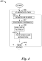
- Figure 4 illustrates a flow diagram of example operations 400 occurring in a JSM unit as the JSM unit manages traffic flows.
- Operations 400 may be indicative of operations occurring in a JSM unit, such as JSM unit 305, as the JSM unit manages traffic flows.
- Operations 400 may begin with the JSM unit classifying traffic flows (block 405).
- the JSM unit may utilize a flow management unit, such as flow management unit 332, to classify traffic flows.
- the JSM unit may classify traffic flows, e.g., video flows, into one or more types in accordance with classification criteria, which may include duration of flow, video flow data rate, available communications system resources (e.g., buffer space, transmission resources, and the like), video flow priority, and the like.
- classification criteria may include duration of flow, video flow data rate, available communications system resources (e.g., buffer space, transmission resources, and the like), video flow priority, and the like.
- the JSM unit may classify traffic flows into one of four different slices (types): one of three video slices (a transit slice, a limbo slice, and a steady slice) or another slice (which may be catch-all for other types of traffic flows in the communications system).
- new video flows are classified as transit slice. However, if the transit slice video queue is overloaded, the video flow may be temporarily classified as limbo slice. Furthermore, if there is not sufficient capacity in the limbo slice video queue, the packets associated with the video flow may be discarded. It is noted that in different example implementations, there may be different numbers of slices. As an illustrative example, there may be more than 3 video slices or less than 3 video slices. Also, there may be multiple other slices for types of traffic flows that are not video flows.
- the JSM unit may also schedule slices (block 406). As the packets of the various packet flows are received in the data plane of the JSM unit, they may be queued in corresponding packet queues. The JSM unit may dequeue packets from the packet queues and forward the packets to respective TPs for transmission to UEs. A multi-node slice scheduler, such as multi-node slice scheduler 334, may perform the dequeuing and forwarding of packets. According to an example embodiment, the JSM unit may dequeue packets from packet queues in such a way as to ensure that the number of transmission resources used to transmit the packets meet a specified ratio.
- the specified ratio may be expressed as St:Ss:So, where St specifies the number of transmission resources used for transit slice packets, Ss specifies the number of transmission resources used for steady slice packets, and So specifies the number of transmission resources used for other slice packets.
- the number of transmission resources used by each packet may be determined as a ratio of packet size in bytes and a current transmission bit rate of the channel (as specified by the MCS of the channel). It is noted that transit slice packets, steady slice packets, and other slice packets receive priority over limbo slice packets during scheduling and that limbo slice packets are scheduled only if there are no transit slice packets.
- the JSM unit may implement different and independent resource management mechanisms for each slice.
- a weighted fair scheduling technique based on the size of the packet flows for the transit slice and the steady slice may be used, while the limbo slice packets may be scheduled using shortest job first scheduling with higher priority being potentially given to important packets (e.g., I frames in H.264 video coding).
- the use of independent scheduling mechanisms may maximize the probability of packet delivery by defining suitable scheduling techniques for different slices.
- the multi-node slice scheduler may not only decide on the scheduling order of the slices, but it may also determine on which interface (i.e., which radio access technology) the packets should be transmitted.
- the multi-node slice scheduler may also ensure that TP scheduling does not interfere with the JSM unit's own scheduling mechanism.
- the multi-node slice scheduler may control implicitly the work of TP scheduling by starving its packet buffers so that its own scheduling algorithms do not have to be used.
- the JSM unit may use utilization information provided by the TPs.
- the JSM unit may receive and process feedback from TPs (block 407). As discussed previously, the JSM unit may receive feedback information, including utilization information, queue status, channel condition information, MCS information, and the like, from the TPs. The JSM unit may use the feedback information to adjust its slice scheduling.
- the JSM unit may evaluate performance metrics (block 408).
- the JSM unit may evaluate one or more metrics for use in adjusting the configuration of the JSM unit.
- the metrics may include delay (e.g., end to end delay), drops (e.g., frame drops, packet drops, and the like), corruption (e.g., corrupted frames, corrupted packets, and the like), re-buffering (e.g., a measure of the amount of freezing time when a particular video flow is displayed), frame rate deviation (e.g., deviation of a video flow's actual frame rate from a pre-defined frame rate), and the like.
- the values of the metrics may be used in flow migration (reclassification) as discussed below.
- the JSM unit may perform flow migration (reclassification) (block 410). It may be necessary or advantageous to change the classification of a packet flow. The changing of the classification of a packet flow may be performed to meet changed conditions, such as overloaded packet queues, underloaded packet queues, TP utilization, and the like.
- Figure 5 illustrates an example classification state diagram 500.
- Classification state diagram 500 may include three states: steady slice 505, transit slice 510, and limbo slice 515. As shown in Figure 5 , a packet flow classified as a transit slice may be reclassified as a steady slice or a limbo slice.
- a packet flow classified as a steady slice may be reclassified as a limbo slice, while a packet flow classified as a limbo slice may be reclassified as a transit slice.
- a packet flow classified as a steady slice may be reclassified as a limbo slice
- a packet flow classified as a limbo slice may be reclassified as a transit slice.
- Figure 6 illustrates a flow diagram of example operations occurring in a JSM unit in reclassifying a packet flow from transit slice to limbo slice.
- Operations 600 may be indicative of operations occurring in a JSM unit, such as JSM unit 305, as the JSM unit reclassifies a packet from transit slice to limbo slice.
- Operations 600 may be scheduled to be performed periodically, such as once every ⁇ 1 units of time.
- Operations 600 may begin with the JSM unit determining a capacity C i and threshold T i for each TP i (block 605).
- the JSM unit may perform a check to determine if capacity C i is greater than threshold T i (block 610). In other words, the JSM unit is determining if the capacity of the flows for TP i is greater than the threshold for TP i . If capacity C i is greater than threshold T i , the JSM unit may migrate (reclassify) a flow w with maximum penalty metric P w from transit slice to limbo slice (block 615).
- the numerator of P w i.e., the average delay delay w
- the denominator of P w indicates that flows with higher bit rates receive better treatment.
- Another way to migrate a packet flow to the limbo slice is when packets of the packet flow reach their maximum delay. In such a situation, packets are migrated to the limbo slice with an expectation that they will be served if there are enough resources. These packets may be dropped by time-out if their delay is greater than ⁇ 2 .
- the JSM unit may determine the size of flow w, B w (block 620) and update the capacity C i (block 625). As an illustrative example, the JSM unit may subtract the size of flow w from the capacity C i . The JSM unit may continue to migrate (reclassify) flows until the capacity C i is no longer greater than threshold T i by returning to block 610. The JSM unit may perform a check to determine if there are any more TPs for which it has not perform flow migration (block 630). If there are more TPs, the JSM unit may select a next i (e.g., increment i ) and return to block 610. If there are no more TPs, operations 600 may terminate.
- a next i e.g., increment i
- a packet flow may be reclassified from a transit slice to a steady slice if the packet flow is active for ⁇ 3 units of time. If there insufficient capacity, the packet flow may be rejected.
- a packet flow may be reclassified from a limbo slice to a transit slice if the packet flow was originally a transit slice and was reclassified as a limbo slice and if the transit slice is not overloaded. If the transit slice is overloaded, the packet flow remains a limbo slice. This reclassification may occur every ⁇ 4 units of time.
- a packet flow may be reclassified from a steady slice to a limbo slice if a packet from the packet flow that is already being served in the steady slice and does not gain access to the steady slice because the steady slice is overloaded (temporarily).
- the packet flow may be migrated to the limbo slice. If there is insufficient capacity in the limbo slice, the packet flow may be discarded.
- the JSM unit may perform a check to determine if it is receiving a new (e.g., unclassified) packet flow (block 415). If the JSM unit is receiving a new packet flow, the JSM unit may return to block 405 to classify the new packet flow. If the JSM unit is not receiving a new packet flow, the JSM unit may return to block 406 to schedule slices.
- a new packet flow e.g., unclassified packet flow
- Figure 7 illustrates an example communications system 700 highlighting UEs simultaneously connected to multiple TPs.
- a situation wherein UEs are simultaneously connected to multiple TP is an important scenario to consider.
- resource allocation across multiple TPs while maximizing overall QoE for the UE is an important consideration.
- a UE 705 may be operating within coverage areas of TP 710 and TP 712. Therefore, UE 705 may be connected to both TP 710 and TP 712.
- Both TP 710 and TP 712 are managed by a JSM unit 715.
- JSM unit 715 controlling both TPs enables the possibility of jointly optimizing the scheduling of packet flows at the TPs, yielding potentially advantageous results.
- JSM unit 715 is capable of handling two or more TPs and efficiently admits and assigns network resources across multiple interfaces.
- a single UE may be simultaneously connected to multiple TPs is when the UE is operating within a coverage area of an eNB and it is also connected to a pico cell or a femto cell or is connected to a Wi-Fi access point.
- a JSM unit may also manage both TPs and enable joint optimization of the scheduling of packet flows to the UE.
- FIG. 8 illustrates a flow diagram of example operations 800 occurring in a JSM unit as the JSM unit schedules network resources in a multiple TP scenario.
- Operations 800 may be indicative of operations occurring in a JSM unit, such as JSM unit 305, as the JSM unit schedules network resources in a situation where multiple TPs are serving a single UE.
- Operations 800 may begin with the JSM unit updating a capacity of TP n , Cap n (block 805).
- the JSM unit may update the capacity every ⁇ units of time, for example.
- R n is the total average served rate of TP n .
- the JSM unit may update a decision metric D n for TP n (block 810).
- the decision metric may be updated for each packet that is to be scheduled by the JSM unit.
- the JSM unit may select a TP to serve the packet. In general, if the packet's destination is served by a single TP, the JSM unit assigns the TP to serve the packet. However, if the packet's destination is served by multiple TPs, the JSM unit assigns the TP based on the decision metric values of the multiple TPs. The JSM unit may perform a check to determine if the packet is destined for a UE served only by a first TP, TPx (block 815).
- the JSM unit schedules the packet to the first TP, TPx (block 820) and moves to block 855 to perform a check to determine if there are additional packets to schedule.
- the JSM unit may perform a check to determine if the packet is destined for a UE served only by a second TP, TPy (block 825). If the UE is served only by the second TP, the JSM unit schedules the packet to the second TP, TPy (block 830) and moves to block 855 to perform a check to determine if there are additional packets to schedule.
- the JSM unit may perform a check to determine if the UE is served by two TPs, TP x and TP y (block 835). If the UE is served by both the first TP and the second TP, the JSM unit may perform a check to determine if the decision metric for TP x , D x , is less than the decision metric for TPy, D y (block 840).
- D y the JSM unit may schedule the packet to the second TP, TP y (block 845) and moves to block 855 to perform a check to determine if there are additional packets to schedule. If the decision metric TPx, D x , is not less than the decision metric for TP y , D y the JSM unit may schedule the packet to the first TP, TPx (block 850) and moves to block 855 to perform a check to determine if there are additional packets to schedule.
- operations 800 illustrates a situation wherein a UE is served by two TPs
- the example embodiments presented herein are also operable in situations where UEs are served by different numbers of TPs, such as three TPs, four TPs, five TPs, and the like.
- the JSM unit may perform a check to determine if there are any additional packets to schedule (block 855). If there are more packets to schedule, the JSM unit may return to block 810 to update the decision metric and schedule additional packets.
- the size of a slice may have a significant impact on the ability of the communications system to meet QoS requirements, as well as achieve QoE targets of the users.
- a slice is too small (e.g., the percentage of resources allocated to the slice is small)
- too many packets may be dropped, yielding a low slice rate, large number of dropped frames or packets, poor quality video, and the like.
- the JSM unit performs dynamic adaptation of slice sizes.
- the JSM unit dynamically adapts the slice sizes using a rate-based utility with constraints on rate, resource balancing between multiple TPs, user QoE, and the like.
- a slice size may be the rate allocated to the slice after performing the optimization.
- Weights may be defined for each slice in accordance with an averaged slice rate, a moving average of slice rate, a rate threshold based on QoE targets or loss rate ratios between packets, and the like.
- the dynamic adaptation of slice sizes may occur periodically (e.g., at specified intervals), when a performance metric is met (such as a frame drop rate, an average slice rate, a QoE target, and the like), when a request to perform dynamic adaptation is received, and the like.
- a performance metric such as a frame drop rate, an average slice rate, a QoE target, and the like
- Figure 9 illustrates a flow diagram of example operations 900 occurring in a JSM unit as the JSM unit dynamically adjusts slice sizes in a single TP situation.
- Operations 900 may be indicative of operations occurring in a JSM unit, such as JSM unit 305, as the JSM unit dynamically adjusts slice sizes in a single TP situation.
- Operations 900 may begin with the JSM unit determining a weight for each slice (block 905).
- the weights for each slice may be determined by optimizing the rates of the slices, for example.
- optimizing the rates of the slices may be achieved by maximizing a utility function of the rates.
- W be the set of packet flows
- I be the index set of video services (corresponding to short duration videos and long duration videos)
- generic index i any given packet flow w ⁇ W belongs to a given slice S i .
- each packet flow w is comprised of many packets p, R S i , is the instantaneous achievable rate (in bits per second) on slice S i , and each slice requires bandwidth provisioning.
- QoE is a function of video quality and takes on values between 0 and 1.
- a practical definition for QoE may be the penalty metric P w discussed previously.
- the maximization of the utilities may be expressed mathematically as: m a x ⁇ i ⁇ I U R S i , where U () is a utility function.
- utility functions may include proportional fairness, weighted fair queuing, and the like.
- the JSM unit may determine the capacity of each slice (block 915).
- the JSM device may send packets to the eNB in accordance with slice capacities (block 920).
- Figure 10 illustrates a flow diagram of example operations 1000 occurring in a JSM unit as the JSM unit jointly performs dynamic slice sizes adjustment and traffic balancing in a multiple TP situation.
- Operations 1000 may be indicative of operations occurring in a JSM unit, such as JSM unit 305, as the JSM unit jointly performs dynamic slice size adjustment and traffic balancing in a multiple TP situation.
- Operations 1000 may begin with the JSM unit determining a weight for each slice on each TP (block 1005).
- the weights for each slice may be determined by optimizing the rates of the slices, for example.
- optimizing the rates of the slices may be achieved by maximizing a utility function of the rates.
- Each slice may be virtually split between the multiple TPs so that the rate allocated to slice i is the sum of rates allocated to slice i over all TPs n ⁇ N .
- the optimization problem (the maximization of the utilities) may be expressed as m a x ⁇ n ⁇ N ⁇ i ⁇ I U R S n , i subject to R S n , i ⁇ R S n , i t h n ⁇ N , i ⁇ I , R S n ⁇ R n n ⁇ N , i ⁇ I , R S n ⁇ ⁇ R n K n ⁇ N , i ⁇ I , P I P n , i ⁇ P B n , i n ⁇ N , i ⁇ I , Q o E ⁇ S n , i ⁇ Q o E S i m i n ⁇ N , i ⁇ I , Equation (5)
- the JSM unit may determine the capacity of each slice (block 1015).
- the JSM device may send packets to the TP in accordance with slice capacities (block 1025).
Description
- The present disclosure relates generally to digital communications, and more particularly to a system and method for transmission management in software defined networks.
- Software Defined Networks (SDNs) offer ease of development, as well as maintenance for network operators. Furthermore, SDNs allow for the isolation of experiments that execute concurrently on a single network. In general, SDNs feature a split data plane and control plane. The split data and control planes typically increase the scalability of the network, as well as ease of configuration.
-
US 2012/002544 relates to dynamic resource partitioning for long-term fairness to non-elastic traffic on a cellular base station. Ravi Kokku ET AL: "Cell Slice: Cellular wireless resource slicing for active RAN sharing", 2013 Fifth International Conference on Communication Systems and Networks (COMSNETS), 1 January 2013 (2013-01-01), pages 1-10, relates to cellular wireless resource slicing for active RAN sharing. - The present invention defines an apparatus according to claim 1 and a method according to claim 9. Further embodiments are set forth in the dependent claims 2-8 and 10.
Example aspects of the present disclosure which provide a system and method for transmission management in software defined networks (SDNs). - In a first aspect, a communications controller is provided, including:
- a flow manager configured to classify a packet flow serviced by more than one transmission points, TPs, as one of a plurality of slices in accordance with at least one of a nature of the packet flow, a load status of each of the plurality of slices, and feedback information provided by the more than one TPs, and to alter a classification of the packet flow in accordance with the load status of each of the plurality of slices, and feedback information provided by the more than one TPs, where, the feedback information provided by the more than one TPs includes the corresponding TP utilization that represents a number of network resources used for packet transmission and a total number of available slots, the currently used modulation and coding scheme, MCS, for each UE, and the signal to interference plus noise ratio, SINR, for each UE;
- a memory operatively coupled to the flow manager, the memory configured to store a packet of the packet flow in one of a plurality of packet queues in accordance with the classification of the packet flow; and
- a scheduler operatively coupled to the flow manager and to the memory, and configured to schedule a transfer of the packet from the one of the plurality of packet queues to at least one TP in accordance with the classification of the packet flow and a destination of the packet;
- where, the communications controller is further configured to:
- determine and update a decision metric value for each of the more than one TPs, where the decision metric of a TP is computed based on a capacity and a total average served rate of the TP; and
- check to determine if the packet is destined for a UE served by one or more TPs and assign a TP selected from the one or more TPs based on the decision metric values of the one or more TPs; and
- the scheduler is further configured to schedule the packet to the one or more TPs, as previously selected based on the decision metric values; and
- where, the communications controller is further configured to:
perform dynamic adaptation of a size of individual slices using a rate-based utility with constraints related to rate, resource balancing between the more than one TPs and user quality of experience, QoE. - In a second aspect, a method for operating a communications controller is provided, the method including:
- receiving, by the communications controller, a packet of a packet flow serviced by more than one transmission points (TPs) controlled by the communications controller;
- classifying, by the communications controller, the packet flow as one of a plurality of slices in accordance with at least one of a nature of the packet flow, a load status of each of the plurality of slices, and feedback information provided by the more than one TPs, , where, the feedback information provided by the more than one TPs includes the corresponding TP utilization that represents a number of network resources used for packet transmission and a total number of available slots, the currently used modulation and coding scheme, MCS, for each UE, and the signal to interference plus noise ratio, SINR, for each UE;
- storing, by the communications controller, the packet in one of a plurality of packet queues in accordance with the classification of the packet flow; and
- scheduling a transfer of the packet from the one of the plurality of packet queues to at least one TP in accordance with the classification of the packet flow and a destination of the packet;
- where, the method further includes:
- altering a classification of the packet flow in accordance with the load status of each of the plurality of slices, and feedback information provided by the more than one TPs;
- where, the method further includes:
- determining and updating a decision metric value for each of the more than one TPs, where the decision metric of a TP is computed based on a capacity and a total average served rate of the TP;
- checking to determine if the packet is destined for a UE served by one or more TPs and assigning a TP selected from the one or more TPs based on the decision metric values of the one or more TPs; and
- scheduling the packet to the one or more TPs, as previously selected based on the decision metric values;
- where, the method further includes:
performing dynamic adaptation of a size of individual slices using a rate-based utility with constraints related to rate, resource balancing between the more than one TPs and user quality of experience, QoE. - One advantage of an aspect is that dynamic adaptation of slices is provided. Therefore, the slices are adaptable dynamically to meet changing operating conditions, thereby helping to ensure that quality of service (QoS) requirements are met. Additionally, data rates of radio nodes are more balanced as operating conditions change.
- A further advantage of an aspect is that slice allocation and management techniques are provided for situations where multiple evolved NodeBs (eNB) transmit to a single user equipment (UE).
- For a more complete understanding of the present disclosure, and the advantages thereof, reference is now made to the following descriptions taken in conjunction with the accompanying drawing, in which:
-
Figure 1 illustrates a first example communications system according to example embodiments described herein; -
Figure 2 illustrates a second example communications system according to example embodiments described herein; -
Figure 3 illustrates a third example communications system highlighting a logical view of a joint slice management (JSM) unit according to example embodiments described herein; -
Figure 4 illustrates a flow diagram of example operations occurring in a JSM unit as the JSM unit manages traffic flows according to example embodiments described herein; -
Figure 5 illustrates an example classification state diagram according to example embodiments described herein; -
Figure 6 illustrates a flow diagram of example operations occurring in a JSM unit in reclassifying a packet flow from transit slice to limbo slice according to example embodiments described herein; -
Figure 7 illustrates an example communications system highlighting UEs simultaneously connected to multiple eNBs according to example embodiments described herein; -
Figure 8 illustrates a flow diagram of example operations occurring in a JSM unit as the JSM unit schedules network resources in a multiple eNB situation according to example embodiments described herein; -
Figure 9 illustrates a flow diagram of example operations occurring in a JSM unit as the JSM unit dynamically adjusts slice sizes in a single eNB situation according to example embodiments described herein; and -
Figure 10 illustrates a flow diagram of example operations occurring in a JSM unit as the JSM unit jointly performs dynamic slice sizes adjustment and traffic balancing in a multiple eNB situation according to example embodiments described herein. - The operating of the current example embodiments and the structure thereof are discussed in detail below. It should be appreciated, however, that the present disclosure provides many applicable inventive ideas that can be embodied in a wide variety of specific contexts. The specific embodiments discussed are merely illustrative of specific structures of the disclosure and ways to operate the disclosure, and do not limit the scope of the disclosure.
- One embodiment of the disclosure relates to transmission management in software defined networks (SDNs). For example, a communications controller receives a packet of a packet flow serviced by more than one transmission points (TPs), classifies the packet flow as one of a plurality of slices in accordance with at least one of a nature of the packet flow, a load status of each of the plurality of slices, and feedback information provided by the more than one TPs, and stores the packet in one of a plurality of packet queues in accordance with the classification of the packet flow.
- The present disclosure will be described with respect to example embodiments in a specific context, namely SDN networks that deliver video content to UEs. The disclosure may be applied to standards compliant communications systems, including heterogeneous communications systems (HetNets), such as those that are compliant with Third Generation Partnership Project (3GPP), IEEE 802.11, and the like, technical standards, and non-standards compliant communications systems, that deliver QoS constrained content to UEs.
-
Figure 1 illustrates a firstexample communications system 100.Communications system 100 includes a plurality of user equipments (UEs), such as UE 105, UE 107, UE 109, and UE 111. The UEs in the plurality of UEs may be served by one or more evolved NodeBs (eNBs), such as eNB 115 and eNB 117. The UEs in the plurality of UEs may also be served by one or more pico cells, such aspico cell 118, as well as femto cells, such asfemto cell 119. The eNBs, pico cells, femto cells, and the like, may provide radio access to the UEs. In general, communications from a UE or to a UE goes through one or more eNBs, pico cells, femto cells, and the like. In some special operating modes, UEs may be able to directly communicate with one another without having an eNB (or pico cell or femto cell) serve as intermediary. - eNBs, pico cells, femto cells, and UEs are terms used to describe some devices in a 3GPP Long Term Evolution (LTE) communications systems, other terms may be used in different communications systems. As an illustrative example, eNBs may also be commonly referred to as base stations, access points, NodeBs, controllers, base station transceiver systems, and the like, while UEs may also be commonly referred to as mobile stations, mobiles, stations, users, subscribers, terminals, and the like. Although the discussion focuses on eNBs, the example embodiments presented herein are operable with other radio access devices, such as remote radio heads, eNB sectors, pico cells, femto cells, access points, and the like (in general, these devices may be referred to as transmission points (TPs)), as well as other radio access technologies, such as IEEE 802.11, Wi-Fi, BlueTooth, WiMAX, and the like. Therefore, the focus on eNBs and LTE should not be construed as being limiting to the scope of the example embodiments.
- The TPs, e.g., eNBs, pico cells, femto cells, and the like, may be connected to a
serving gateway 120, which may be referred to generically as a local anchor. Servinggateway 120 may typically handle mobility and user session management. A packet data network gateway (PDN gateway) 125 may connect servinggateway 120 to an Internet Protocol (IP) network, such as theInternet 130.PDN gateway 125 may also handle QoS policies or billing functions. In a WiMAX communications system, the gateways may be referred to as application service network gateway (ASN) and content service network gateway (CSN). - While it is understood that communications systems may employ multiple TPs (e.g., eNBs, pico cells, femto cells, and the like) capable of communicating with a number of UEs, only four TPs (2 eNBs, 1 pico cell, and 1 femto cell), and a number of UEs are illustrated for simplicity.
- According to an example embodiment, the SDN architecture in conjunction with wireless access offers value-added wireless video transmission services to video content providers. The SDN architecture enables the use of a centralized control plane that is able to control different access technologies. Any given UE may be served by one or more TPs, potentially using different radio access technologies, including but not limited to LTE, Wi-Fi, WiMAX, Bluetooth, and the like.
- It is noted that although the discussion focuses on video transmission and video content delivery, the example embodiments discussed herein are operable with other forms of content transmission, especially content that has QoS constraints, performance sensitivity, and the like. Examples of such content may include voice, health monitoring, emergency monitoring, and the like.
-
Figure 2 illustrates a secondexample communications system 200.Communications system 200 includes acentralized control plane 205, that among other things, performs flow level management that typically establishes a list of actions to be taken for each flow matching a particular rule, and virtualizes network resources through slicing and enables the coexistence of multiple types of services or operators with different routing or policies on a single physical infrastructure. -
Centralized control plane 205 may be coupled to serving gateways (such as servinggateways 210 and 212) and PDN gateways (such asPDN gateways 215 and 217).Centralized control plane 205 may specify the distribution of packets from avideo content provider 220 that is connected to the PDN gateways and the serving gateways throughInternet 225. The distribution of packets fromvideo content provider 220, as well as packets from other services, may be specified by the classification of flows (e.g., video flows), as well as operating conditions of communications system 200 (including load status of video flow queues, TP load, UE load, channel condition, and the like). - The packets from video content provider 220 (as well as packets from other services) may be provided to TPs (such as TPs 230 - 234) for delivery to UEs (such as UEs 240 - 248).
Centralized control plane 205 may specify which TPs receive which video packets. As an illustrative example, a TP that is not serving any UE subscribed to a specified video flow is unlikely to receive any packets associated with the specified video flow. As another illustrative example, if two (or more) TPs are cooperating to serve a video flow to a UE, then the TPs involved will be provided with packets associated with the video flow for delivery to the UE. -
Figure 3 illustrates a thirdexample communications system 300 highlighting a logical view of a joint slide management (JSM) unit.Communications system 300 includes a JSM unit 305 (shown in a logical form) that may be coupled in between anInternet 310 and a plurality of TPs (such as TPs 310 - 314) that are serving a plurality of UEs (such as UEs 320 - 326). - According to an example embodiment,
JSM unit 305 may operate as a centralized controller that jointly handles flow admission control (e.g., classification of packet flows, queuing or dropping of packet flows, and the like) and scheduling of packet transfers, as well as other operations.JSM unit 305 may take advantage of SDN architecture that splits the data plane and the control plane, mainly to virtualize the wireless access network and to allow for differentiated services for packet traffic, such as for video packet traffic. As a result,JSM unit 305 may be able to handle UEs simultaneously connected to multiple eNBs.JSM unit 305 may group packet flows with similar characteristics into slices within the data plane.JSM unit 305 may manage wireless resource allocation procedures across slices, as well as multiple TPs, using the control plane. - In general,
JSM unit 305 may be capable of handling packets for UEs connected to multiple TPs. QoS restrictions, such as minimum offered rate, maximum tolerable delay, and the like, are set between UEs and communications operators. Hence,JSM unit 305 may not be involved with specifying QoS restrictions. However, operation ofJSM unit 305 may be determined based on the QoS restrictions. Furthermore, the TPs may provide periodic feedback toJSM unit 305. The periodic feedback may include: TP utilization (a number of network resources used for packet transmission and a total number of available slots), currently used modulation and coding scheme (MCS) for each UE, and a signal to interference plus noise ratio (SINR) for each UE.JSM unit 305 may take the feedback information into consideration as it controls the packet flow to the UEs through the TPs. -
JSM unit 305 may virtualize and support multiple TPs, multiple radio access technologies (RATs), as well as multiple frequency bands.JSM unit 305 may also dynamically adapt allocated resources of slices according to an optimization framework with an aim to maximize utility functions of the slices while trying to ensure that QoS restrictions are met. Furthermore,JSM unit 305 may also balance the packet traffic between adjacent TPs in order to avoid congestion, while maximizing TP utilization. Additionally,JSM unit 305 may increase the quality of experience (QoE) for UEs by minimizing dropped packets. -
JSM unit 305 may include acontrol plane 330 and adata plane 340.Control plane 330 may be an example implementation of logicallycentralized control plane 205 ofFigure 2 , whiledata plane 340 may be a logical representation of a serving gateway(s) and a PDN gateway(s).Control plane 330 may include aflow management unit 332 configured to implement a migration strategy, which controls changes in the classification of a video flow. According to an example embodiment, the migration strategy takes into consideration information such as video flow classification, slice status (e.g., slice load, slice queue size, and the like), TP status (e.g., TP capacity, channel capacity, channel condition, and the like), performance metrics, and the like, to change the classification of a video flow. Detailed discussion of example migration strategies are provided below.Control plane 330 may also include amulti-node slice scheduler 334 and asynchronizer 336.Multi-node slice scheduler 334 may be configured to schedule the transfer of packets of video flows fromdata plane 340 to TPs. Although referred to as a multi-node scheduler,multi-node slice scheduler 334 may operate in situations where single TPs are serving UEs as well as situations where multi-TPs are serving UEs.Synchronizer 336 may be configured to coordinate the operations ofdata plane 340, e.g., serving gateway(s) and PDN gateway(s). - Logically,
data plane 340 may include a plurality of packet queues, such asvideo traffic queues 342, as well asother traffic queues 344. As an illustrative example, if video flows are classified into one of three possible video slices, thenvideo traffic queues 342 may include three separate video queues. It is noted that although shown inFigure 3 as including three video queues,video traffic queues 342 may include a different number of video queues, generally one video queue for each video slice. However, for video slices with relatively light packet traffic, it may be possible to use a single video queue for more than one video slice. It is also noted that although shown inFigure 3 as a single queue,other traffic queues 344 may include a different number of queues, typically one queue for each different classification of other traffic although a single queue may be used for more than one classification of other traffic.Data plane 340 may also include aflow classifier 350.Flow classifier 350 may direct packets of packet flows to a packet queue associated with the packets. As an illustrative example,data plane 340 may direct packets of video flows to a video queue invideo traffic queues 342 and packets of other packet flows toother traffic queues 344. - As discussed previously,
data plane 340 may be a logical representation of serving gateway(s) and PDN gateway(s). Therefore, the packet queues may be implemented in the serving gateway(s) only, the PDN gateway(s) only, or a combination of the serving gateway(s) and the PDN gateways. Additionally, in an example implementation whereindata plane 340 is implemented over multiple serving gateways and PDN gateways, the packet queues may be implemented over the multiple serving gateways and PDN gateways. Alternatively, a serving gateway and PDN gateway may implement a particular packet queue only if a UE associated with them is receiving packets associated with the particular queue. As an illustrative example, if a UE is receiving a first video flow, then the serving gateway and PDN gateway associated with a TP serving the UE may implement the video queue associated with the first video flow. - Although shown in
Figure 3 as including a single JSM unit, a communications system may include more than one JSM unit. As an illustrative example, different JSM units may be implemented in different geographical areas of the communications system. As another illustrative example, different JSM units may be implemented to manage different types of packet flows. As yet another illustrative example, different portions of the communications may be managed by different JSM units with each JSM unit potentially managing traffic flows in different ways. -
Figure 4 illustrates a flow diagram ofexample operations 400 occurring in a JSM unit as the JSM unit manages traffic flows.Operations 400 may be indicative of operations occurring in a JSM unit, such asJSM unit 305, as the JSM unit manages traffic flows. -
Operations 400 may begin with the JSM unit classifying traffic flows (block 405). The JSM unit may utilize a flow management unit, such asflow management unit 332, to classify traffic flows. The JSM unit may classify traffic flows, e.g., video flows, into one or more types in accordance with classification criteria, which may include duration of flow, video flow data rate, available communications system resources (e.g., buffer space, transmission resources, and the like), video flow priority, and the like. As an illustrative example, the JSM unit may classify traffic flows into one of four different slices (types): one of three video slices (a transit slice, a limbo slice, and a steady slice) or another slice (which may be catch-all for other types of traffic flows in the communications system). In general, new video flows are classified as transit slice. However, if the transit slice video queue is overloaded, the video flow may be temporarily classified as limbo slice. Furthermore, if there is not sufficient capacity in the limbo slice video queue, the packets associated with the video flow may be discarded. It is noted that in different example implementations, there may be different numbers of slices. As an illustrative example, there may be more than 3 video slices or less than 3 video slices. Also, there may be multiple other slices for types of traffic flows that are not video flows. - The JSM unit may also schedule slices (block 406). As the packets of the various packet flows are received in the data plane of the JSM unit, they may be queued in corresponding packet queues. The JSM unit may dequeue packets from the packet queues and forward the packets to respective TPs for transmission to UEs. A multi-node slice scheduler, such as
multi-node slice scheduler 334, may perform the dequeuing and forwarding of packets. According to an example embodiment, the JSM unit may dequeue packets from packet queues in such a way as to ensure that the number of transmission resources used to transmit the packets meet a specified ratio. As an illustrative example, the specified ratio may be expressed as St:Ss:So, where St specifies the number of transmission resources used for transit slice packets, Ss specifies the number of transmission resources used for steady slice packets, and So specifies the number of transmission resources used for other slice packets. The number of transmission resources used by each packet may be determined as a ratio of packet size in bytes and a current transmission bit rate of the channel (as specified by the MCS of the channel). It is noted that transit slice packets, steady slice packets, and other slice packets receive priority over limbo slice packets during scheduling and that limbo slice packets are scheduled only if there are no transit slice packets. - According to an example embodiment, the JSM unit may implement different and independent resource management mechanisms for each slice. As an illustrative example, a weighted fair scheduling technique based on the size of the packet flows for the transit slice and the steady slice may be used, while the limbo slice packets may be scheduled using shortest job first scheduling with higher priority being potentially given to important packets (e.g., I frames in H.264 video coding). The use of independent scheduling mechanisms may maximize the probability of packet delivery by defining suitable scheduling techniques for different slices.
- The multi-node slice scheduler may not only decide on the scheduling order of the slices, but it may also determine on which interface (i.e., which radio access technology) the packets should be transmitted. The multi-node slice scheduler may also ensure that TP scheduling does not interfere with the JSM unit's own scheduling mechanism. As an example, the multi-node slice scheduler may control implicitly the work of TP scheduling by starving its packet buffers so that its own scheduling algorithms do not have to be used. The JSM unit may use utilization information provided by the TPs.
- The JSM unit may receive and process feedback from TPs (block 407). As discussed previously, the JSM unit may receive feedback information, including utilization information, queue status, channel condition information, MCS information, and the like, from the TPs. The JSM unit may use the feedback information to adjust its slice scheduling.
- The JSM unit may evaluate performance metrics (block 408). The JSM unit may evaluate one or more metrics for use in adjusting the configuration of the JSM unit. Examples of the metrics may include delay (e.g., end to end delay), drops (e.g., frame drops, packet drops, and the like), corruption (e.g., corrupted frames, corrupted packets, and the like), re-buffering (e.g., a measure of the amount of freezing time when a particular video flow is displayed), frame rate deviation (e.g., deviation of a video flow's actual frame rate from a pre-defined frame rate), and the like. The values of the metrics may be used in flow migration (reclassification) as discussed below.
- The JSM unit may perform flow migration (reclassification) (block 410). It may be necessary or advantageous to change the classification of a packet flow. The changing of the classification of a packet flow may be performed to meet changed conditions, such as overloaded packet queues, underloaded packet queues, TP utilization, and the like.
Figure 5 illustrates an example classification state diagram 500. Classification state diagram 500 may include three states:steady slice 505,transit slice 510, andlimbo slice 515. As shown inFigure 5 , a packet flow classified as a transit slice may be reclassified as a steady slice or a limbo slice. Similarly, a packet flow classified as a steady slice may be reclassified as a limbo slice, while a packet flow classified as a limbo slice may be reclassified as a transit slice. Detailed discussions of example reclassifications of packet flow classification are presented below. -
Figure 6 illustrates a flow diagram of example operations occurring in a JSM unit in reclassifying a packet flow from transit slice to limbo slice.Operations 600 may be indicative of operations occurring in a JSM unit, such asJSM unit 305, as the JSM unit reclassifies a packet from transit slice to limbo slice.Operations 600 may be scheduled to be performed periodically, such as once every θ1 units of time. -
Operations 600 may begin with the JSM unit determining a capacity Ci and threshold Ti for each TP i (block 605). For a given packet flow w, the capacity Ci may account for the capacity of flows Fw in the transit slice associated with the UE connected to TPi plus a proportion of the capacity of flows Fw connected to multiple TPs, which may be expressed mathematically as:

- Then, for an initial i (e.g., i=0), the JSM unit may perform a check to determine if capacity Ci is greater than threshold Ti (block 610). In other words, the JSM unit is determining if the capacity of the flows for TPi is greater than the threshold for TPi. If capacity Ci is greater than threshold Ti, the JSM unit may migrate (reclassify) a flow w with maximum penalty metric Pw from transit slice to limbo slice (block 615). As an example, the penalty metric may be a function of actual bit rate Rw of flow w and an average delay delayw of flow w, which may be expressed mathematically as:

- Another way to migrate a packet flow to the limbo slice is when packets of the packet flow reach their maximum delay. In such a situation, packets are migrated to the limbo slice with an expectation that they will be served if there are enough resources. These packets may be dropped by time-out if their delay is greater than θ2.
- The JSM unit may determine the size of flow w, Bw (block 620) and update the capacity Ci (block 625). As an illustrative example, the JSM unit may subtract the size of flow w from the capacity Ci . The JSM unit may continue to migrate (reclassify) flows until the capacity Ci is no longer greater than threshold Ti by returning to block 610. The JSM unit may perform a check to determine if there are any more TPs for which it has not perform flow migration (block 630). If there are more TPs, the JSM unit may select a next i (e.g., increment i) and return to block 610. If there are no more TPs,
operations 600 may terminate. - Similarly, a packet flow may be reclassified from a transit slice to a steady slice if the packet flow is active for θ3 units of time. If there insufficient capacity, the packet flow may be rejected.
- Additionally, a packet flow may be reclassified from a limbo slice to a transit slice if the packet flow was originally a transit slice and was reclassified as a limbo slice and if the transit slice is not overloaded. If the transit slice is overloaded, the packet flow remains a limbo slice. This reclassification may occur every θ4 units of time.
- Furthermore, a packet flow may be reclassified from a steady slice to a limbo slice if a packet from the packet flow that is already being served in the steady slice and does not gain access to the steady slice because the steady slice is overloaded (temporarily). The packet flow may be migrated to the limbo slice. If there is insufficient capacity in the limbo slice, the packet flow may be discarded.
- Returning now to
Figure 4 , the JSM unit may perform a check to determine if it is receiving a new (e.g., unclassified) packet flow (block 415). If the JSM unit is receiving a new packet flow, the JSM unit may return to block 405 to classify the new packet flow. If the JSM unit is not receiving a new packet flow, the JSM unit may return to block 406 to schedule slices. -
Figure 7 illustrates anexample communications system 700 highlighting UEs simultaneously connected to multiple TPs. As discussed previously, a situation wherein UEs are simultaneously connected to multiple TP is an important scenario to consider. In such a situation, resource allocation across multiple TPs while maximizing overall QoE for the UE is an important consideration. As shown inFigure 7 , aUE 705 may be operating within coverage areas ofTP 710 andTP 712. Therefore,UE 705 may be connected to bothTP 710 andTP 712. - Both
TP 710 andTP 712 are managed by aJSM unit 715.JSM unit 715 controlling both TPs enables the possibility of jointly optimizing the scheduling of packet flows at the TPs, yielding potentially advantageous results.JSM unit 715 is capable of handling two or more TPs and efficiently admits and assigns network resources across multiple interfaces. - Another situation where a single UE may be simultaneously connected to multiple TPs is when the UE is operating within a coverage area of an eNB and it is also connected to a pico cell or a femto cell or is connected to a Wi-Fi access point. In such a situation, a JSM unit may also manage both TPs and enable joint optimization of the scheduling of packet flows to the UE.
-
Figure 8 illustrates a flow diagram ofexample operations 800 occurring in a JSM unit as the JSM unit schedules network resources in a multiple TP scenario.Operations 800 may be indicative of operations occurring in a JSM unit, such asJSM unit 305, as the JSM unit schedules network resources in a situation where multiple TPs are serving a single UE. -
Operations 800 may begin with the JSM unit updating a capacity of TPn, Capn (block 805). The JSM unit may update the capacity every δ units of time, for example. An example capacity may be expressed mathematically as:
- The JSM unit may update a decision metric Dn for TPn (block 810). In general, the decision metric may be updated for each packet that is to be scheduled by the JSM unit. An example decision metric may be expressed mathematically as:

- For a given packet, the JSM unit may select a TP to serve the packet. In general, if the packet's destination is served by a single TP, the JSM unit assigns the TP to serve the packet. However, if the packet's destination is served by multiple TPs, the JSM unit assigns the TP based on the decision metric values of the multiple TPs. The JSM unit may perform a check to determine if the packet is destined for a UE served only by a first TP, TPx (block 815). If the UE is served only by the first TP, the JSM unit schedules the packet to the first TP, TPx (block 820) and moves to block 855 to perform a check to determine if there are additional packets to schedule. The JSM unit may perform a check to determine if the packet is destined for a UE served only by a second TP, TPy (block 825). If the UE is served only by the second TP, the JSM unit schedules the packet to the second TP, TPy (block 830) and moves to block 855 to perform a check to determine if there are additional packets to schedule.
- If the UE is not served by only one TP, the JSM unit may perform a check to determine if the UE is served by two TPs, TPx and TPy (block 835). If the UE is served by both the first TP and the second TP, the JSM unit may perform a check to determine if the decision metric for TPx, Dx, is less than the decision metric for TPy, Dy (block 840). If the decision metric TPx, Dx, is less than the decision metric for TPy, Dy the JSM unit may schedule the packet to the second TP, TPy (block 845) and moves to block 855 to perform a check to determine if there are additional packets to schedule. If the decision metric TPx, Dx, is not less than the decision metric for TPy, Dy the JSM unit may schedule the packet to the first TP, TPx (block 850) and moves to block 855 to perform a check to determine if there are additional packets to schedule. Although
operations 800 illustrates a situation wherein a UE is served by two TPs, the example embodiments presented herein are also operable in situations where UEs are served by different numbers of TPs, such as three TPs, four TPs, five TPs, and the like. - The JSM unit may perform a check to determine if there are any additional packets to schedule (block 855). If there are more packets to schedule, the JSM unit may return to block 810 to update the decision metric and schedule additional packets.
- The size of a slice (e.g., a percentage of resources, such as buffer space, allocated to a slice) may have a significant impact on the ability of the communications system to meet QoS requirements, as well as achieve QoE targets of the users. As an illustrative example, if a slice is too small (e.g., the percentage of resources allocated to the slice is small), too many packets may be dropped, yielding a low slice rate, large number of dropped frames or packets, poor quality video, and the like.
- According to an example embodiment, the JSM unit performs dynamic adaptation of slice sizes. The JSM unit dynamically adapts the slice sizes using a rate-based utility with constraints on rate, resource balancing between multiple TPs, user QoE, and the like. A slice size may be the rate allocated to the slice after performing the optimization. Weights may be defined for each slice in accordance with an averaged slice rate, a moving average of slice rate, a rate threshold based on QoE targets or loss rate ratios between packets, and the like. The dynamic adaptation of slice sizes may occur periodically (e.g., at specified intervals), when a performance metric is met (such as a frame drop rate, an average slice rate, a QoE target, and the like), when a request to perform dynamic adaptation is received, and the like.
-
Figure 9 illustrates a flow diagram ofexample operations 900 occurring in a JSM unit as the JSM unit dynamically adjusts slice sizes in a single TP situation.Operations 900 may be indicative of operations occurring in a JSM unit, such asJSM unit 305, as the JSM unit dynamically adjusts slice sizes in a single TP situation. -
Operations 900 may begin with the JSM unit determining a weight for each slice (block 905). The weights for each slice may be determined by optimizing the rates of the slices, for example. As an illustrative example, optimizing the rates of the slices may be achieved by maximizing a utility function of the rates. However, it may also be possible to optimize the rates of the slices by minimizing a different utility function of the rates. For discussion purposes, let W be the set of packet flows, I be the index set of video services (corresponding to short duration videos and long duration videos), and generic index i. Any given packet flow w ∈ W belongs to a given slice Si . Furthermore, assume that each packet flow w is comprised of many packets p, RSi , is the instantaneous achievable rate (in bits per second) on slice Si , and each slice requires bandwidth provisioning. Additionally, QoE is a function of video quality and takes on values between 0 and 1. A practical definition for QoE may be the penalty metric Pw discussed previously. - For a given time step δ, the maximization of the utilities may be expressed mathematically as:


R Si is the average slice rate taken over n time steps, and Pi = PBi /PIPi ); Equation (2) ensures that the total assigned rate has to be smaller than the total available rate R; Equation (3) ensures that the dropping probability of important packets (1-PIP ) is smaller than the dropping probability of unimportant packets (1-PB ); and Equation (4) ensures a minimum QoE on all slices, withQoE S being the average quality of experience for slice Si taken over n time steps, andi 
- The utility function may be modeled as a concave function with respect to RS
i , so it is convenient to re-express the maximization of utilities as
- The exponential moving average weight on each slice,


- The JSM unit may normalize the weights (Σweigth i = 1) (block 910). The JSM unit may determine the capacity of each slice (block 915). As an illustrative example, the capacity of slice i may be expressed as

-
Figure 10 illustrates a flow diagram ofexample operations 1000 occurring in a JSM unit as the JSM unit jointly performs dynamic slice sizes adjustment and traffic balancing in a multiple TP situation.Operations 1000 may be indicative of operations occurring in a JSM unit, such asJSM unit 305, as the JSM unit jointly performs dynamic slice size adjustment and traffic balancing in a multiple TP situation. -
Operations 1000 may begin with the JSM unit determining a weight for each slice on each TP (block 1005). The weights for each slice may be determined by optimizing the rates of the slices, for example. As an illustrative example, optimizing the rates of the slices may be achieved by maximizing a utility function of the rates. However, it may also be possible to optimize the rates of the slices by minimizing a different utility function of the rates. In order to generalize to the multiple TP situation, it may be necessary to index quantities with both a slice number (i ∈ I) and a TP number (n ∈ N). Each slice may be virtually split between the multiple TPs so that the rate allocated to slice i is the sum of rates allocated to slice i over all TPs n ∈ N. The optimization problem (the maximization of the utilities) may be expressed as


n,i assigned to each slice is at least equal to the reserved rate for each slice


RS is the average slice rate taken over δ time steps and Pn,i = P B n,i /PIPn,i n,i ; Equation (6) ensures that the total assigned rate is smaller than the total achievable rate on TPn; Equation (7) ensures that the average rate managed by each TP is proportional to the total achievable rate Rn , where RSn = Σi RSn,i , K is a parameter that ensures traffic balancing, and may be chosen at iteration t such that


QoE Sn,i as the average quality of experience for slice Sn,i and TPn taken over δ time steps, and
- The utility function may be modeled as a concave function with respect to RS
n,i , so it is convenient to re-express the maximization of utilities as
- The exponential moving average weight on each slice,


- The JSM unit may normalize the weights (∑weighti = 1) (block 1010). The JSM unit may determine the capacity of each slice (block 1015). As an illustrative example, the capacity of slice i may be expressed as


- The following examples are also defined:
- Example 1. The method of claim 15, wherein adjusting the capacities comprises maximize a utility function of the rates of the plurality of slices.
- Example 2. The method of claim 11, wherein classifying the packet flow comprises:
- initially classifying the packet flow as a first slice of the plurality of slices; and
- subsequently reclassifying the packet flow as the one of the plurality of slices in accordance with at least one of the nature of the packet flow, the load status of each of the plurality of slices, and feedback information provided by the more than one TPs.
- Example 3. The method of Example 2, wherein the packet flow comprises a video flow, wherein the plurality of slices comprises a transit slice, a limbo slice, and a steady slice, and wherein the first slice is the transit slice.
- Example 4. The method of Example 2, wherein the packet is reclassified in accordance with one of a penalty metric associated with the packet flow and a delay associated with the packet of the packet flow.
- Example 5. A communications system comprising:
- a plurality of transmission points (TPs) configured to serve user equipments; and
- a communications controller operatively coupled to the plurality of TPs, the communications controller configured to classify a packet flow serviced by more than one TPs of the plurality of TPs as one of a plurality of slices in accordance with at least one of a nature of the packet flow, a load status of each of the plurality of slices, and feedback information provided by the plurality of TPs controlled by the communications controller, to alter a classification of the packet flow in accordance with the load status of each of the plurality of slices, and feedback information provided by the plurality of TPs, and to store a packet of the packet flow in one of a plurality of packet queues in accordance with the classification of the packet flow.
- Example 6. The communications controller of Example 5, wherein the communications controller comprises:
- a control plane configured to classify the packet flow as the one of the plurality of slices in accordance with at least one of the nature of the packet flow, the load status of each of the plurality of slices, and feedback information provided by the plurality of TPs, and to alter the classification of the packet flow in accordance with the load status of each of the plurality of slices, and the feedback information provided by the plurality of TPs; and
- a data plane operatively coupled to the control plane, the data plane configured to store the packet of the packet flow in the one of the plurality of packet queues in accordance with the classification of the packet flow.
- Although the present disclosure and its advantages have been described in detail, it should be understood that various changes, substitutions and alterations can be made herein without departing from the scope of the disclosure as defined by the appended claims.
Claims (10)
- A communications controller (305) comprising:a flow manager (332) configured to classify a packet flow serviced by more than one transmission points, TPs (230, 234, 244), as one of a plurality of slices in accordance with at least one of a nature of the packet flow, a load status of each of the plurality of slices, and feedback information provided by the more than one TPs (230, 234, 244), and to alter a classification of the packet flow in accordance with the load status of each of the plurality of slices, and the feedback information provided by the more than one TPs (230, 234, 244), wherein the feedback information provided by the more than one TPs (230, 234, 244) includes a corresponding TP (230, 234, 244) utilization that represents a number of network resources used for packet transmission and a total number of available slots, a currently used modulation and coding scheme, MCS, for each user equipment, UE, (240, 246, 248) connected to one or more of the more than one TPs (230, 234, 244), and a signal to interference plus noise ratio, SINR, for each UE (240, 246, 248);a memory operatively coupled to the flow manager (332), the memory configured to store a packet of the packet flow in one of a plurality of packet queues in accordance with the classification of the packet flow; anda scheduler (334) operatively coupled to the flow manager (332) and to the memory, and configured to schedule a transfer of the packet from the one of the plurality of packet queues to at least one TP (230, 234, 244) in accordance with the classification of the packet flow and a destination of the packet;wherein, the communications controller (305) is further configured to: determine and update a capacity for each of the more than one TPs (230, 234, 244);
determine and update a decision metric value for each of the more than one TPs (230, 234, 244), wherein the decision metric value is computed based on the capacity and a total average served rate of the TP (230, 234, 244); and determine if the packet is destined for a UE (240, 246, 248) served by only one TP (230, 234, 244) or by more than one TPs (230, 234, 244) and
select a TP (230, 234, 244) from the one or more TPs (230, 234, 244) to serve the packet,
wherein the selection is made based on the previous determination and based on the decision metric values of the one or more TPs (230, 234, 244); andthe scheduler (334) is further configured to schedule the packet to the TP (230, 234, 244), as previously selected based on the decision metric values; andwherein, the communications controller (305) is further configured to: perform dynamic adaptation of sizes of the plurality of slices by using a rate-based utility with constraints on rate, resource balancing between the more than one TPs (230, 234, 244) and user quality of experience, QoE. - The communications controller of claim 1, wherein the scheduler is configured to adjust capacities of the plurality of packet queues in accordance with an optimization of rates of the plurality of slices.
- The communications controller of claim 2, wherein the scheduler is configured to maximize a utility function of the rates of the plurality of slices.
- The communications controller of claim 3, wherein the utility function is a concave function with respect to the rates of the plurality of slices.
- The communications controller of claim 1, wherein the flow manager is configured to initially classify the packet flow as a first slice of the plurality of slices, and wherein the flow manager is configured to subsequently reclassify the packet flow as the one of the plurality of slices in accordance with at least one of the nature of the packet flow, the load status of each of the plurality of slices, and feedback information provided by the more than one TPs.
- The communications controller of claim 5, wherein the packet flow comprises a video flow, wherein the plurality of slices comprises a transit slice, a limbo slice, and a steady slice, and wherein the first slice is the transit slice.
- The communications controller of claim 5, wherein the flow manager is configured to subsequently reclassify the packet flow in accordance with a penalty metric associated with the packet flow.
- The communications controller of claim 5, wherein the flow manager is configured to subsequently reclassify the packet flow in accordance with a delay associated with the packet of the packet flow.
- A method for operating a communications controller, the method comprising:receiving (415), by the communications controller, a packet of a packet flow serviced by more than one transmission points, TPs, controlled by the communications controller;classifying (405), by the communications controller, the packet flow as one of a plurality of slices in accordance with at least one of a nature of the packet flow, a load status of each of the plurality of slices, and feedback information provided by the more than one TPs, wherein the feedback information provided by the more than one TPs includes a corresponding TP utilization that represents a number of network resources used for packet transmission and a total number of available slots, a currently used modulation and coding scheme, MCS, for each user equipment, UE, connected to one or more of the more than one TPs, and a signal to interference plus noise ratio, SINR, for each UE;storing, in a memory of the communications controller, the packet in one of a plurality of packet queues in accordance with the classification of the packet flow; andscheduling (406), by a scheduler of the communications controller, a transfer of the packet from the one of the plurality of packet queues to at least one TP in accordance with the classification of the packet flow and a destination of the packet;wherein, the method further comprises: altering, by the communications controller, a classification of the packet flow in accordance with the load status of each of the plurality of slices, and feedback information provided by the more than one TPs;wherein, the method further comprises: determining and updating (805), by the communications controller, a capacity for each of the more than one TPs;determining and updating (810), by the communications controller, a decision metric value for each of the more than one TPs, wherein the decision metric value is computed based on the capacity and a total average served rate of the TP;determining (815, 825, 835), by the communications controller, if the packet is destined for a UE served by only one TP or by more than one TPs and selecting, by the communications controller, a TP from the one or more TPs to serve the packet, wherein the selection is made based on the previous determination and based on decision metric values of the one or more TPs; andscheduling (820, 830, 845, 850), by the scheduler of the communications controller, the packet to the TP, as previously selected based on the decision metric values;wherein, the method further comprises: performing (915, 1015), by the communications controller, dynamic adaptation of sizes of the plurality of slices by using a rate-based utility with constraints on rate, resource balancing between the more than one TPs and user quality of experience, QoE.
- The method of claim 9, further comprising adjusting capacities of the plurality of packet queues in accordance with an optimization of rates of the plurality of slices.
Applications Claiming Priority (2)
| Application Number | Priority Date | Filing Date | Title |
|---|---|---|---|
| US14/516,394 US9722935B2 (en) | 2014-10-16 | 2014-10-16 | System and method for transmission management in software defined networks |
| PCT/CN2015/091162 WO2016058482A1 (en) | 2014-10-16 | 2015-09-30 | System and method for transmission management in software defined networks |
Publications (3)
| Publication Number | Publication Date |
|---|---|
| EP3198836A1 EP3198836A1 (en) | 2017-08-02 |
| EP3198836A4 EP3198836A4 (en) | 2017-09-06 |
| EP3198836B1 true EP3198836B1 (en) | 2018-09-19 |
Family
ID=55746118
Family Applications (1)
| Application Number | Title | Priority Date | Filing Date |
|---|---|---|---|
| EP15851007.3A Active EP3198836B1 (en) | 2014-10-16 | 2015-09-30 | System and method for transmission management in software defined networks |
Country Status (4)
| Country | Link |
|---|---|
| US (1) | US9722935B2 (en) |
| EP (1) | EP3198836B1 (en) |
| CN (1) | CN106716955B (en) |
| WO (1) | WO2016058482A1 (en) |
Cited By (1)
| Publication number | Priority date | Publication date | Assignee | Title |
|---|---|---|---|---|
| US20220286410A1 (en) * | 2019-11-15 | 2022-09-08 | Charter Communications Operating, Llc | Network quality of service controller |
Families Citing this family (38)
| Publication number | Priority date | Publication date | Assignee | Title |
|---|---|---|---|---|
| US10548063B1 (en) * | 2015-11-24 | 2020-01-28 | Sprint Spectrum L.P. | Call admission control for relay access nodes |
| JP6480641B2 (en) * | 2016-05-26 | 2019-03-13 | 京セラ株式会社 | Network equipment |
| US10149193B2 (en) | 2016-06-15 | 2018-12-04 | At&T Intellectual Property I, L.P. | Method and apparatus for dynamically managing network resources |
| CN107659419B (en) * | 2016-07-25 | 2021-01-01 | 华为技术有限公司 | Network slicing method and system |
| CN112637928B (en) * | 2016-09-07 | 2022-06-14 | 华为技术有限公司 | Access control method and device |
| US10284730B2 (en) | 2016-11-01 | 2019-05-07 | At&T Intellectual Property I, L.P. | Method and apparatus for adaptive charging and performance in a software defined network |
| US10454836B2 (en) | 2016-11-01 | 2019-10-22 | At&T Intellectual Property I, L.P. | Method and apparatus for dynamically adapting a software defined network |
| US10505870B2 (en) | 2016-11-07 | 2019-12-10 | At&T Intellectual Property I, L.P. | Method and apparatus for a responsive software defined network |
| US10469376B2 (en) | 2016-11-15 | 2019-11-05 | At&T Intellectual Property I, L.P. | Method and apparatus for dynamic network routing in a software defined network |
| US10039006B2 (en) | 2016-12-05 | 2018-07-31 | At&T Intellectual Property I, L.P. | Method and system providing local data breakout within mobility networks |
| US10264075B2 (en) * | 2017-02-27 | 2019-04-16 | At&T Intellectual Property I, L.P. | Methods, systems, and devices for multiplexing service information from sensor data |
| US10469286B2 (en) | 2017-03-06 | 2019-11-05 | At&T Intellectual Property I, L.P. | Methods, systems, and devices for managing client devices using a virtual anchor manager |
| US10631367B2 (en) | 2017-04-14 | 2020-04-21 | Verizon Patent And Licensing Inc. | Virtualized equipment for multi-network and cross cell utilization |
| US10470079B2 (en) | 2017-04-14 | 2019-11-05 | Verizon Patent And Licensing Inc. | Systems and method for cross cell aggregation using virtualized equipment |
| US10749796B2 (en) | 2017-04-27 | 2020-08-18 | At&T Intellectual Property I, L.P. | Method and apparatus for selecting processing paths in a software defined network |
| US10673751B2 (en) | 2017-04-27 | 2020-06-02 | At&T Intellectual Property I, L.P. | Method and apparatus for enhancing services in a software defined network |
| US10819606B2 (en) | 2017-04-27 | 2020-10-27 | At&T Intellectual Property I, L.P. | Method and apparatus for selecting processing paths in a converged network |
| US10212289B2 (en) | 2017-04-27 | 2019-02-19 | At&T Intellectual Property I, L.P. | Method and apparatus for managing resources in a software defined network |
| US10257668B2 (en) | 2017-05-09 | 2019-04-09 | At&T Intellectual Property I, L.P. | Dynamic network slice-switching and handover system and method |
| US10382903B2 (en) | 2017-05-09 | 2019-08-13 | At&T Intellectual Property I, L.P. | Multi-slicing orchestration system and method for service and/or content delivery |
| WO2018205150A1 (en) | 2017-05-09 | 2018-11-15 | 华为技术有限公司 | Network slice selection policy updating method and apparatus |
| JP6730961B2 (en) * | 2017-06-20 | 2020-07-29 | 日本電信電話株式会社 | Service slice performance monitoring system and service slice performance monitoring method |
| US10070344B1 (en) | 2017-07-25 | 2018-09-04 | At&T Intellectual Property I, L.P. | Method and system for managing utilization of slices in a virtual network function environment |
| CN107819774B (en) * | 2017-11-16 | 2021-05-28 | 郑州云海信息技术有限公司 | SDN heterogeneous multi-controller cooperation method and system |
| US10104548B1 (en) | 2017-12-18 | 2018-10-16 | At&T Intellectual Property I, L.P. | Method and apparatus for dynamic instantiation of virtual service slices for autonomous machines |
| CN109996296B (en) * | 2018-01-02 | 2021-08-06 | 中国移动通信有限公司研究院 | Method and equipment for adjusting bandwidth |
| WO2019241404A1 (en) * | 2018-06-15 | 2019-12-19 | Orock Technologies, Inc. | Secure on-premise to cloud communication |
| CN111030775B (en) * | 2018-10-10 | 2021-04-13 | 中国移动通信有限公司研究院 | Data transmission method, device and equipment |
| US10944647B2 (en) | 2019-01-24 | 2021-03-09 | Vmware, Inc. | Dynamic inter-cloud placement of virtual network functions for a slice |
| US10979314B2 (en) | 2019-01-24 | 2021-04-13 | Vmware, Inc. | Dynamic inter-cloud placement of virtual network functions for a slice |
| US11588733B2 (en) | 2019-05-14 | 2023-02-21 | Vmware, Inc. | Slice-based routing |
| US10958579B2 (en) | 2019-05-14 | 2021-03-23 | Vmware, Inc. | Congestion avoidance in a slice-based network |
| US11012288B2 (en) | 2019-05-14 | 2021-05-18 | Vmware, Inc. | Congestion avoidance in a slice-based network |
| US10897423B2 (en) | 2019-05-14 | 2021-01-19 | Vmware, Inc. | Congestion avoidance in a slice-based network |
| US10892994B2 (en) * | 2019-05-14 | 2021-01-12 | Vmware, Inc. | Quality of service in virtual service networks |
| CN114124831A (en) * | 2020-08-28 | 2022-03-01 | 中国移动通信集团终端有限公司 | Data transmission method, device, equipment and storage medium |
| CN112423267B (en) * | 2020-10-14 | 2022-04-22 | 南京大学 | Vehicle networking heterogeneous resource dynamic slicing method based on Lyapunov random optimization |
| US11310146B1 (en) | 2021-03-27 | 2022-04-19 | Netflow, UAB | System and method for optimal multiserver VPN routing |
Family Cites Families (17)
| Publication number | Priority date | Publication date | Assignee | Title |
|---|---|---|---|---|
| US20090006521A1 (en) | 2007-06-29 | 2009-01-01 | Veal Bryan E | Adaptive receive side scaling |
| US20090296613A1 (en) * | 2008-06-03 | 2009-12-03 | Colin Kahn | Method and apparatus for providing quality-of-service in radio access networks |
| CN101998494B (en) * | 2009-08-21 | 2016-02-03 | 华为技术有限公司 | The method of Business Stream shared resource, system and IAD |
| EP2504952A1 (en) * | 2009-11-27 | 2012-10-03 | Telefonaktiebolaget LM Ericsson (publ) | Packet classification method and apparatus |
| US8767553B2 (en) * | 2010-07-02 | 2014-07-01 | Nec Laboratories America, Inc. | Dynamic resource partitioning for long-term fairness to non-elastic traffic on a cellular basestation |
| CN102075984B (en) | 2010-12-31 | 2013-06-12 | 北京邮电大学 | System and method for optimizing video service transmission of wireless local area network |
| WO2013093786A2 (en) * | 2011-12-20 | 2013-06-27 | Marvell World Trade Ltd. | Reference signal design for coordinated multipoint transmission |
| US8718064B2 (en) * | 2011-12-22 | 2014-05-06 | Telefonaktiebolaget L M Ericsson (Publ) | Forwarding element for flexible and extensible flow processing software-defined networks |
| US8521905B2 (en) * | 2011-12-22 | 2013-08-27 | Telefonaktiebolaget L M Ericsson (Publ) | System for flexible and extensible flow processing in software-defined networks |
| CN102724317B (en) * | 2012-06-21 | 2016-05-25 | 华为技术有限公司 | A kind of network traffic data sorting technique and device |
| US9094459B2 (en) | 2012-07-16 | 2015-07-28 | International Business Machines Corporation | Flow based overlay network |
| CN106170024B (en) | 2012-12-24 | 2019-12-24 | 华为技术有限公司 | System, method and node for data processing in software defined network |
| US9692706B2 (en) * | 2013-04-15 | 2017-06-27 | International Business Machines Corporation | Virtual enhanced transmission selection (VETS) for lossless ethernet |
| US9461967B2 (en) * | 2013-07-18 | 2016-10-04 | Palo Alto Networks, Inc. | Packet classification for network routing |
| EP3036938A4 (en) * | 2013-08-23 | 2017-04-12 | Samsung Electronics Co., Ltd. | Mobile software defined networking (mobisdn) |
| CN103560963B (en) | 2013-11-18 | 2016-08-17 | 中国科学院计算机网络信息中心 | A kind of OpenFlow flow table memory space compression method |
| US9413659B2 (en) * | 2014-06-11 | 2016-08-09 | Cisco Technology, Inc. | Distributed network address and port translation for migrating flows between service chains in a network environment |
-
2014
- 2014-10-16 US US14/516,394 patent/US9722935B2/en active Active
-
2015
- 2015-09-30 EP EP15851007.3A patent/EP3198836B1/en active Active
- 2015-09-30 WO PCT/CN2015/091162 patent/WO2016058482A1/en active Application Filing
- 2015-09-30 CN CN201580049479.0A patent/CN106716955B/en active Active
Non-Patent Citations (1)
| Title |
|---|
| None * |
Cited By (2)
| Publication number | Priority date | Publication date | Assignee | Title |
|---|---|---|---|---|
| US20220286410A1 (en) * | 2019-11-15 | 2022-09-08 | Charter Communications Operating, Llc | Network quality of service controller |
| US11979337B2 (en) * | 2019-11-15 | 2024-05-07 | Charter Communications Operating, Llc | Network quality of service controller |
Also Published As
| Publication number | Publication date |
|---|---|
| CN106716955B (en) | 2019-11-26 |
| US9722935B2 (en) | 2017-08-01 |
| CN106716955A (en) | 2017-05-24 |
| WO2016058482A1 (en) | 2016-04-21 |
| US20160112335A1 (en) | 2016-04-21 |
| EP3198836A4 (en) | 2017-09-06 |
| EP3198836A1 (en) | 2017-08-02 |
Similar Documents
| Publication | Publication Date | Title |
|---|---|---|
| EP3198836B1 (en) | System and method for transmission management in software defined networks | |
| JP5788554B2 (en) | Methods for partitioning partition entities and capacity | |
| US10834614B2 (en) | Quality of service in wireless backhauls | |
| US10306670B2 (en) | Systems and methods for a smart gateway SDN-based backhaul architecture for small cells | |
| US8755405B2 (en) | Burst packet scheduler for improved ran efficiency in UMTS/HSPA networks | |
| US8767553B2 (en) | Dynamic resource partitioning for long-term fairness to non-elastic traffic on a cellular basestation | |
| EP3251451B1 (en) | Method and device for selecting uplink data | |
| EP2936908B1 (en) | Method and system for scheduling radio resources in cellular networks | |
| WO2013190364A2 (en) | Systems and methods for resource booking for admission control and scheduling using drx | |
| Mansouri et al. | Radio resource management for heterogeneous wireless networks: Schemes and simulation analysis | |
| Lawal et al. | Downlink scheduling algorithms in LTE networks: a survey | |
| Chagdali et al. | Impact of slice function placement on the performance of URLLC with redundant coverage | |
| Gran et al. | Towards wireless infrastructure-as-a-service (WlaaS) for 5G software-defined cellular systems | |
| US11950130B2 (en) | Systems and methods for rate control of ingress traffic in a radio access network | |
| Zhou et al. | Managing background traffic in cellular networks | |
| JP5432811B2 (en) | Wireless communication system and gateway device | |
| Lee et al. | Uplink QoS scheduling algorithm with delay estimation for LTE systems | |
| Saed et al. | Low Complexity in Exaggerated Earliest Deadline First Approach for Channel and QoS-aware Scheduler. | |
| Kuboye | Comparative analysis of scheduling algorithms performance in a Long Term Evolution Network | |
| Maniru | Enhanced Adaptive Call Admission Control (EA-CAC) Scheme with Bandwidth Reservation for LTE Networks | |
| Khdhir et al. | Scheduling algorithm for multiclass services in LTE network | |
| Paymard et al. | PDU-set Scheduling Algorithm for XR Traffic in Multi-Service 5G-Advanced Networks | |
| Pizzi et al. | Channel-aware class-based scheduling for QoS support in IEEE 802.16/WiMAX networks | |
| Hendaoui | Study Of Quality Of Service Framework In 5G Network And Proposed Smart Scheduling Policy Based On Slicing And Network Virtualization |
Legal Events
| Date | Code | Title | Description |
|---|---|---|---|
| PUAI | Public reference made under article 153(3) epc to a published international application that has entered the european phase |
Free format text: ORIGINAL CODE: 0009012 |
|
| 17P | Request for examination filed |
Effective date: 20170427 |
|
| AK | Designated contracting states |
Kind code of ref document: A1 Designated state(s): AL AT BE BG CH CY CZ DE DK EE ES FI FR GB GR HR HU IE IS IT LI LT LU LV MC MK MT NL NO PL PT RO RS SE SI SK SM TR |
|
| AX | Request for extension of the european patent |
Extension state: BA ME |
|
| A4 | Supplementary search report drawn up and despatched |
Effective date: 20170807 |
|
| RIC1 | Information provided on ipc code assigned before grant |
Ipc: H04L 29/06 20060101AFI20170801BHEP Ipc: H04L 12/70 20130101ALI20170801BHEP Ipc: H04L 12/851 20130101ALI20170801BHEP Ipc: H04W 28/02 20090101ALI20170801BHEP |
|
| DAV | Request for validation of the european patent (deleted) | ||
| DAX | Request for extension of the european patent (deleted) | ||
| GRAP | Despatch of communication of intention to grant a patent |
Free format text: ORIGINAL CODE: EPIDOSNIGR1 |
|
| INTG | Intention to grant announced |
Effective date: 20180329 |
|
| GRAS | Grant fee paid |
Free format text: ORIGINAL CODE: EPIDOSNIGR3 |
|
| GRAA | (expected) grant |
Free format text: ORIGINAL CODE: 0009210 |
|
| AK | Designated contracting states |
Kind code of ref document: B1 Designated state(s): AL AT BE BG CH CY CZ DE DK EE ES FI FR GB GR HR HU IE IS IT LI LT LU LV MC MK MT NL NO PL PT RO RS SE SI SK SM TR |
|
| REG | Reference to a national code |
Ref country code: GB Ref legal event code: FG4D |
|
| REG | Reference to a national code |
Ref country code: CH Ref legal event code: EP |
|
| REG | Reference to a national code |
Ref country code: AT Ref legal event code: REF Ref document number: 1044603 Country of ref document: AT Kind code of ref document: T Effective date: 20181015 |
|
| REG | Reference to a national code |
Ref country code: IE Ref legal event code: FG4D |
|
| REG | Reference to a national code |
Ref country code: DE Ref legal event code: R096 Ref document number: 602015016794 Country of ref document: DE |
|
| REG | Reference to a national code |
Ref country code: NL Ref legal event code: MP Effective date: 20180919 |
|
| PG25 | Lapsed in a contracting state [announced via postgrant information from national office to epo] |
Ref country code: GR Free format text: LAPSE BECAUSE OF FAILURE TO SUBMIT A TRANSLATION OF THE DESCRIPTION OR TO PAY THE FEE WITHIN THE PRESCRIBED TIME-LIMIT Effective date: 20181220 Ref country code: FI Free format text: LAPSE BECAUSE OF FAILURE TO SUBMIT A TRANSLATION OF THE DESCRIPTION OR TO PAY THE FEE WITHIN THE PRESCRIBED TIME-LIMIT Effective date: 20180919 Ref country code: NO Free format text: LAPSE BECAUSE OF FAILURE TO SUBMIT A TRANSLATION OF THE DESCRIPTION OR TO PAY THE FEE WITHIN THE PRESCRIBED TIME-LIMIT Effective date: 20181219 Ref country code: BG Free format text: LAPSE BECAUSE OF FAILURE TO SUBMIT A TRANSLATION OF THE DESCRIPTION OR TO PAY THE FEE WITHIN THE PRESCRIBED TIME-LIMIT Effective date: 20181219 Ref country code: SE Free format text: LAPSE BECAUSE OF FAILURE TO SUBMIT A TRANSLATION OF THE DESCRIPTION OR TO PAY THE FEE WITHIN THE PRESCRIBED TIME-LIMIT Effective date: 20180919 Ref country code: RS Free format text: LAPSE BECAUSE OF FAILURE TO SUBMIT A TRANSLATION OF THE DESCRIPTION OR TO PAY THE FEE WITHIN THE PRESCRIBED TIME-LIMIT Effective date: 20180919 Ref country code: LT Free format text: LAPSE BECAUSE OF FAILURE TO SUBMIT A TRANSLATION OF THE DESCRIPTION OR TO PAY THE FEE WITHIN THE PRESCRIBED TIME-LIMIT Effective date: 20180919 |
|
| REG | Reference to a national code |
Ref country code: LT Ref legal event code: MG4D |
|
| PG25 | Lapsed in a contracting state [announced via postgrant information from national office to epo] |
Ref country code: AL Free format text: LAPSE BECAUSE OF FAILURE TO SUBMIT A TRANSLATION OF THE DESCRIPTION OR TO PAY THE FEE WITHIN THE PRESCRIBED TIME-LIMIT Effective date: 20180919 Ref country code: LV Free format text: LAPSE BECAUSE OF FAILURE TO SUBMIT A TRANSLATION OF THE DESCRIPTION OR TO PAY THE FEE WITHIN THE PRESCRIBED TIME-LIMIT Effective date: 20180919 Ref country code: HR Free format text: LAPSE BECAUSE OF FAILURE TO SUBMIT A TRANSLATION OF THE DESCRIPTION OR TO PAY THE FEE WITHIN THE PRESCRIBED TIME-LIMIT Effective date: 20180919 |
|
| REG | Reference to a national code |
Ref country code: AT Ref legal event code: MK05 Ref document number: 1044603 Country of ref document: AT Kind code of ref document: T Effective date: 20180919 |
|
| PG25 | Lapsed in a contracting state [announced via postgrant information from national office to epo] |
Ref country code: ES Free format text: LAPSE BECAUSE OF FAILURE TO SUBMIT A TRANSLATION OF THE DESCRIPTION OR TO PAY THE FEE WITHIN THE PRESCRIBED TIME-LIMIT Effective date: 20180919 Ref country code: PL Free format text: LAPSE BECAUSE OF FAILURE TO SUBMIT A TRANSLATION OF THE DESCRIPTION OR TO PAY THE FEE WITHIN THE PRESCRIBED TIME-LIMIT Effective date: 20180919 Ref country code: IS Free format text: LAPSE BECAUSE OF FAILURE TO SUBMIT A TRANSLATION OF THE DESCRIPTION OR TO PAY THE FEE WITHIN THE PRESCRIBED TIME-LIMIT Effective date: 20190119 Ref country code: CZ Free format text: LAPSE BECAUSE OF FAILURE TO SUBMIT A TRANSLATION OF THE DESCRIPTION OR TO PAY THE FEE WITHIN THE PRESCRIBED TIME-LIMIT Effective date: 20180919 Ref country code: AT Free format text: LAPSE BECAUSE OF FAILURE TO SUBMIT A TRANSLATION OF THE DESCRIPTION OR TO PAY THE FEE WITHIN THE PRESCRIBED TIME-LIMIT Effective date: 20180919 Ref country code: IT Free format text: LAPSE BECAUSE OF FAILURE TO SUBMIT A TRANSLATION OF THE DESCRIPTION OR TO PAY THE FEE WITHIN THE PRESCRIBED TIME-LIMIT Effective date: 20180919 Ref country code: NL Free format text: LAPSE BECAUSE OF FAILURE TO SUBMIT A TRANSLATION OF THE DESCRIPTION OR TO PAY THE FEE WITHIN THE PRESCRIBED TIME-LIMIT Effective date: 20180919 Ref country code: EE Free format text: LAPSE BECAUSE OF FAILURE TO SUBMIT A TRANSLATION OF THE DESCRIPTION OR TO PAY THE FEE WITHIN THE PRESCRIBED TIME-LIMIT Effective date: 20180919 Ref country code: RO Free format text: LAPSE BECAUSE OF FAILURE TO SUBMIT A TRANSLATION OF THE DESCRIPTION OR TO PAY THE FEE WITHIN THE PRESCRIBED TIME-LIMIT Effective date: 20180919 |
|
| REG | Reference to a national code |
Ref country code: CH Ref legal event code: PL |
|
| PG25 | Lapsed in a contracting state [announced via postgrant information from national office to epo] |
Ref country code: SM Free format text: LAPSE BECAUSE OF FAILURE TO SUBMIT A TRANSLATION OF THE DESCRIPTION OR TO PAY THE FEE WITHIN THE PRESCRIBED TIME-LIMIT Effective date: 20180919 Ref country code: PT Free format text: LAPSE BECAUSE OF FAILURE TO SUBMIT A TRANSLATION OF THE DESCRIPTION OR TO PAY THE FEE WITHIN THE PRESCRIBED TIME-LIMIT Effective date: 20190119 Ref country code: SK Free format text: LAPSE BECAUSE OF FAILURE TO SUBMIT A TRANSLATION OF THE DESCRIPTION OR TO PAY THE FEE WITHIN THE PRESCRIBED TIME-LIMIT Effective date: 20180919 |
|
| REG | Reference to a national code |
Ref country code: BE Ref legal event code: MM Effective date: 20180930 |
|
| REG | Reference to a national code |
Ref country code: DE Ref legal event code: R097 Ref document number: 602015016794 Country of ref document: DE |
|
| REG | Reference to a national code |
Ref country code: IE Ref legal event code: MM4A |
|
| PG25 | Lapsed in a contracting state [announced via postgrant information from national office to epo] |
Ref country code: LU Free format text: LAPSE BECAUSE OF NON-PAYMENT OF DUE FEES Effective date: 20180930 |
|
| PLBE | No opposition filed within time limit |
Free format text: ORIGINAL CODE: 0009261 |
|
| STAA | Information on the status of an ep patent application or granted ep patent |
Free format text: STATUS: NO OPPOSITION FILED WITHIN TIME LIMIT |
|
| PG25 | Lapsed in a contracting state [announced via postgrant information from national office to epo] |
Ref country code: DK Free format text: LAPSE BECAUSE OF FAILURE TO SUBMIT A TRANSLATION OF THE DESCRIPTION OR TO PAY THE FEE WITHIN THE PRESCRIBED TIME-LIMIT Effective date: 20180919 Ref country code: IE Free format text: LAPSE BECAUSE OF NON-PAYMENT OF DUE FEES Effective date: 20180930 Ref country code: MC Free format text: LAPSE BECAUSE OF FAILURE TO SUBMIT A TRANSLATION OF THE DESCRIPTION OR TO PAY THE FEE WITHIN THE PRESCRIBED TIME-LIMIT Effective date: 20180919 |
|
| 26N | No opposition filed |
Effective date: 20190620 |
|
| PG25 | Lapsed in a contracting state [announced via postgrant information from national office to epo] |
Ref country code: LI Free format text: LAPSE BECAUSE OF NON-PAYMENT OF DUE FEES Effective date: 20180930 Ref country code: CH Free format text: LAPSE BECAUSE OF NON-PAYMENT OF DUE FEES Effective date: 20180930 Ref country code: BE Free format text: LAPSE BECAUSE OF NON-PAYMENT OF DUE FEES Effective date: 20180930 |
|
| PG25 | Lapsed in a contracting state [announced via postgrant information from national office to epo] |
Ref country code: FR Free format text: LAPSE BECAUSE OF NON-PAYMENT OF DUE FEES Effective date: 20181119 Ref country code: SI Free format text: LAPSE BECAUSE OF FAILURE TO SUBMIT A TRANSLATION OF THE DESCRIPTION OR TO PAY THE FEE WITHIN THE PRESCRIBED TIME-LIMIT Effective date: 20180919 |
|
| PG25 | Lapsed in a contracting state [announced via postgrant information from national office to epo] |
Ref country code: MT Free format text: LAPSE BECAUSE OF NON-PAYMENT OF DUE FEES Effective date: 20180930 |
|
| PG25 | Lapsed in a contracting state [announced via postgrant information from national office to epo] |
Ref country code: TR Free format text: LAPSE BECAUSE OF FAILURE TO SUBMIT A TRANSLATION OF THE DESCRIPTION OR TO PAY THE FEE WITHIN THE PRESCRIBED TIME-LIMIT Effective date: 20180919 |
|
| PG25 | Lapsed in a contracting state [announced via postgrant information from national office to epo] |
Ref country code: HU Free format text: LAPSE BECAUSE OF FAILURE TO SUBMIT A TRANSLATION OF THE DESCRIPTION OR TO PAY THE FEE WITHIN THE PRESCRIBED TIME-LIMIT; INVALID AB INITIO Effective date: 20150930 Ref country code: MK Free format text: LAPSE BECAUSE OF NON-PAYMENT OF DUE FEES Effective date: 20180919 Ref country code: CY Free format text: LAPSE BECAUSE OF FAILURE TO SUBMIT A TRANSLATION OF THE DESCRIPTION OR TO PAY THE FEE WITHIN THE PRESCRIBED TIME-LIMIT Effective date: 20180919 |
|
| PGFP | Annual fee paid to national office [announced via postgrant information from national office to epo] |
Ref country code: GB Payment date: 20200923 Year of fee payment: 6 |
|
| REG | Reference to a national code |
Ref country code: DE Ref legal event code: R079 Ref document number: 602015016794 Country of ref document: DE Free format text: PREVIOUS MAIN CLASS: H04L0029060000 Ipc: H04L0065000000 |
|
| GBPC | Gb: european patent ceased through non-payment of renewal fee |
Effective date: 20210930 |
|
| PG25 | Lapsed in a contracting state [announced via postgrant information from national office to epo] |
Ref country code: GB Free format text: LAPSE BECAUSE OF NON-PAYMENT OF DUE FEES Effective date: 20210930 |
|
| PGFP | Annual fee paid to national office [announced via postgrant information from national office to epo] |
Ref country code: DE Payment date: 20230808 Year of fee payment: 9 |