EP3198798B1 - Compilateur et procédé pour mise en réseau, stockage et détermination informatique, définis par logiciel, de ressources virtuelles et physiques - Google Patents
Compilateur et procédé pour mise en réseau, stockage et détermination informatique, définis par logiciel, de ressources virtuelles et physiques Download PDFInfo
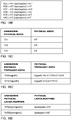
- Publication number
- EP3198798B1 EP3198798B1 EP15791787.3A EP15791787A EP3198798B1 EP 3198798 B1 EP3198798 B1 EP 3198798B1 EP 15791787 A EP15791787 A EP 15791787A EP 3198798 B1 EP3198798 B1 EP 3198798B1
- Authority
- EP
- European Patent Office
- Prior art keywords
- physical
- topology
- mapping
- node
- logical
- Prior art date
- Legal status (The legal status is an assumption and is not a legal conclusion. Google has not performed a legal analysis and makes no representation as to the accuracy of the status listed.)
- Active
Links
- 238000000034 method Methods 0.000 title claims description 193
- 230000006855 networking Effects 0.000 title description 58
- 238000013507 mapping Methods 0.000 claims description 1208
- 230000009471 action Effects 0.000 claims description 114
- 238000004364 calculation method Methods 0.000 claims description 20
- 238000004590 computer program Methods 0.000 claims description 6
- 238000010586 diagram Methods 0.000 description 106
- 230000003247 decreasing effect Effects 0.000 description 21
- 101000958771 Homo sapiens N-acylethanolamine-hydrolyzing acid amidase Proteins 0.000 description 15
- 102100038360 N-acylethanolamine-hydrolyzing acid amidase Human genes 0.000 description 15
- 238000013459 approach Methods 0.000 description 13
- 230000008569 process Effects 0.000 description 11
- 230000006870 function Effects 0.000 description 10
- 230000006399 behavior Effects 0.000 description 6
- 239000000835 fiber Substances 0.000 description 6
- 230000008878 coupling Effects 0.000 description 5
- 238000010168 coupling process Methods 0.000 description 5
- 238000005859 coupling reaction Methods 0.000 description 5
- 238000005516 engineering process Methods 0.000 description 5
- 238000007726 management method Methods 0.000 description 5
- 238000012986 modification Methods 0.000 description 5
- 230000004048 modification Effects 0.000 description 5
- 230000003287 optical effect Effects 0.000 description 5
- 230000009286 beneficial effect Effects 0.000 description 4
- 230000010354 integration Effects 0.000 description 4
- 230000008093 supporting effect Effects 0.000 description 4
- 230000002457 bidirectional effect Effects 0.000 description 3
- 230000003139 buffering effect Effects 0.000 description 3
- 238000004891 communication Methods 0.000 description 3
- 230000018109 developmental process Effects 0.000 description 3
- 238000012544 monitoring process Methods 0.000 description 3
- 239000000344 soap Substances 0.000 description 3
- 229920001621 AMOLED Polymers 0.000 description 2
- RYGMFSIKBFXOCR-UHFFFAOYSA-N Copper Chemical compound [Cu] RYGMFSIKBFXOCR-UHFFFAOYSA-N 0.000 description 2
- 230000000903 blocking effect Effects 0.000 description 2
- 239000000872 buffer Substances 0.000 description 2
- 238000006243 chemical reaction Methods 0.000 description 2
- 239000003795 chemical substances by application Substances 0.000 description 2
- 229910052802 copper Inorganic materials 0.000 description 2
- 239000010949 copper Substances 0.000 description 2
- 238000011161 development Methods 0.000 description 2
- 238000005538 encapsulation Methods 0.000 description 2
- 238000007689 inspection Methods 0.000 description 2
- 230000008520 organization Effects 0.000 description 2
- 238000012913 prioritisation Methods 0.000 description 2
- 230000001360 synchronised effect Effects 0.000 description 2
- 238000012546 transfer Methods 0.000 description 2
- 238000013519 translation Methods 0.000 description 2
- 241000590419 Polygonia interrogationis Species 0.000 description 1
- 230000002730 additional effect Effects 0.000 description 1
- 238000004458 analytical method Methods 0.000 description 1
- 230000008901 benefit Effects 0.000 description 1
- 230000005540 biological transmission Effects 0.000 description 1
- 239000000969 carrier Substances 0.000 description 1
- 230000021615 conjugation Effects 0.000 description 1
- 230000001419 dependent effect Effects 0.000 description 1
- 230000002708 enhancing effect Effects 0.000 description 1
- 238000002955 isolation Methods 0.000 description 1
- 238000002372 labelling Methods 0.000 description 1
- 239000004973 liquid crystal related substance Substances 0.000 description 1
- 238000013508 migration Methods 0.000 description 1
- 230000005012 migration Effects 0.000 description 1
- 239000013307 optical fiber Substances 0.000 description 1
- 238000004321 preservation Methods 0.000 description 1
- 238000007639 printing Methods 0.000 description 1
- 238000012545 processing Methods 0.000 description 1
- 230000004044 response Effects 0.000 description 1
- 239000007787 solid Substances 0.000 description 1
- 230000005641 tunneling Effects 0.000 description 1
Images


Classifications
-
- H—ELECTRICITY
- H04—ELECTRIC COMMUNICATION TECHNIQUE
- H04L—TRANSMISSION OF DIGITAL INFORMATION, e.g. TELEGRAPHIC COMMUNICATION
- H04L45/00—Routing or path finding of packets in data switching networks
- H04L45/02—Topology update or discovery
-
- H—ELECTRICITY
- H04—ELECTRIC COMMUNICATION TECHNIQUE
- H04L—TRANSMISSION OF DIGITAL INFORMATION, e.g. TELEGRAPHIC COMMUNICATION
- H04L41/00—Arrangements for maintenance, administration or management of data switching networks, e.g. of packet switching networks
- H04L41/12—Discovery or management of network topologies
- H04L41/122—Discovery or management of network topologies of virtualised topologies, e.g. software-defined networks [SDN] or network function virtualisation [NFV]
-
- H—ELECTRICITY
- H04—ELECTRIC COMMUNICATION TECHNIQUE
- H04L—TRANSMISSION OF DIGITAL INFORMATION, e.g. TELEGRAPHIC COMMUNICATION
- H04L49/00—Packet switching elements
- H04L49/25—Routing or path finding in a switch fabric
- H04L49/252—Store and forward routing
-
- H—ELECTRICITY
- H04—ELECTRIC COMMUNICATION TECHNIQUE
- H04L—TRANSMISSION OF DIGITAL INFORMATION, e.g. TELEGRAPHIC COMMUNICATION
- H04L49/00—Packet switching elements
- H04L49/70—Virtual switches
Definitions
- the present invention relates to communication networks, storage equipment and computing equipment. Such networks may be packet-switched or circuit-switched.
- the present invention relates to a method for configuring packet forwarding devices, computing equipment, storage equipment, virtual switches, virtual machines and containers in physical and virtual networks.
- the current leading protocol for this is OpenFlow, but the present invention is not limited or bound to the OpenFlow protocol, but generic in nature and could work with future protocols that provide programmatic access to forwarding table(s) of packet forwarding devices.
- the forwarding table(s) contains the information against which information from the incoming packet and input port is matched, providing the desired output port(s) to forward the packet out to.
- 'packet forwarding device' as 'switch' throughout the remainder of this document, referencing to any device performing packet forwarding, not limited to Open Systems Interconnection (OSI) Layer 2.
- OSI Open Systems Interconnection
- a switch might provide additional operation(s) on the packet, such as but not limited to monitoring and/or recording and/or buffering and/or modifying of the incoming packet header and/or payload before forwarding the packet to one or more of it's output ports.
- the switch might also not forward (block) the packet.
- middleboxes are typically referred to as middleboxes and are included in the definition of a switch used in this document.
- NFV Network Functions Virtualization
- the distribution of these forwarding tables to switches is typically done by a so-called 'SDN controller'.
- the SDN controller is functionally a central place (implementations are typically redundant) at which the centrally specified forwarding tables are distributed among the typically geographically distributed switches in the network. Further, the SDN controller provides at its northbound interface a centralized view of the physical and/or virtual network resources, e.g. switches in the network, their topology, status of individual links.
- a host could be instructed over which interface to send a packet to a particular destination node.
- a host could be instructed which packets to accept and which to drop.
- a NIC could be instructed which packets to forward and which to drop. This requires a holistic approach to Software Defined Networking including physical and virtual networking, storage and computing resources.
- US 2013/058215 discloses a virtualizer for managing a plurality of managed switching elements that forward data through a network.
- the virtualizer comprises a first set of tables for storing input logical forwarding plane data and a second set of tables for storing output physical control plane data. It also includes a table mapping engine for mapping the input logical forwarding plane data in the first set of tables to output physical control plane data in the second set of tables by performing a set of database join operations on the input logical forwarding plane data in the first set of tables.
- the physical control plane data is subsequently translated into physical forwarding behaviors that direct the forwarding of data by the managed switching elements.
- a managed switch converts this physical control plane data to physical forwarding plane data that specifies the forwarding behavior of the managed switch (cf. [0197]), having the disadvantage of placing a requirement on physical nodes to perform this conversion and using resources in said physical nodes.
- the prior art presented in US2013/044641 creates an overlay virtual network, in terminology of this application a logical network, based on tunnels in an underlay, typically IP-based network. This approach has the disadvantage of operating both the virtual overlay network and the underlay network complicating operations.
- the prior art according to US2013/044641 models a virtual node, in terminology of this application a logical node, after a physical node, having the disadvantage of continuing to configure and manage networks based on network element operations rather than network services.
- PCT/EP2014/055640 describes a method for translating or compiling a high-level network specification into a set of instructions for the appropriate physical and/or virtual networking and/or computing resources. These instructions state which actions to perform on incoming packets such as forwarding, receiving, dropping incoming packets as well as how to send packets from a source node.
- the invention described in PCT/EP2014/055640 also relates to a SDN compiler arranged to perform such a method.
- the SDN compiler retains a model of each logical network that is defined through a high-level network specification. Also, the SDN compiler retains a model of physical and/or virtual networking and/or computing resources. Both models as well as their relationship are represented in a set of relations, such as matrices.
- the logical network comprises logical nodes.
- the forwarding path between each logical source and logical destination node is determined through operations performed on these matrices resulting in a list of Points-of-Attachments (e.g. but not limited to an Ethernet Media Access Control (MAC) Address) of physical and virtual resources. From these forwarding paths stored in matrices the above mentioned appropriate instructions are derived.
- MAC Media Access Control
- the method described in PCT/EP2014/055640 can be applied to currently available OpenFlow-based products, but is not limited to OpenFlow and could work with future protocols that provide programmatic access to forwarding table(s) of packet forwarding devices.
- the described method can be applied to currently widely used identifiers of Point-of-Attachment, such as Ethernet MAC Addresses.
- the described method can be applied to IPv4 and IPv6 naming and packet formats.
- the invention described in PCT/EP2014/055640 does not require any conversion in a physical node, creating forwarding entries that can directly be used for making forwarding decisions on incoming packets, allowing for less complex forwarding hardware and software forwarding implementations.
- the described invention does not require an underlay network, simplifying operations, by compiling a logical network using a logical namespace to physical networking resources.
- the described invention uses a network abstraction based on a directed graph allowing a user of an SDN Compiler to specify network services based on declarative request, and an SDN Compiler to implement and maintain said network services, simplifying operations and allowing for specifying, implementing and maintaining complex network services.
- PCT/EP2014/055640 describes a method for translating or compiling a high-level network specification into a set of instructions for the appropriate physical and/or virtual networking and/or computing resources.
- PCT/EP2014/055640 can be applied to an overall network in which a logical node at a highest layer denotes logical storage or logical compute and in which a requested-topology-level-path denotes a logical message-stream.
- the present invention provides a method as claimed in claim 1.
- the SDN Compiler method described in PCT/EP2014/055640 is extended to determine depth-mappings, relating nodes at different depths, by an SDN Compiler based on requirements of logical nodes, logical-topology-mappings, and optionally logical layer-mappings, specified by a user of an SDN Compiler.
- Said extension allows a user of an SDN Compiler to specify logical nodes, requirements of logical nodes, logical topology-mappings and requirements of logical-topology-mappings, and optionally logical layer-mappings and requirements of logical layer-mappings and have said SDN Compiler determine physical and/or virtual resources, comprising of physical nodes and physical links, against which said logical specification can be compiled, thereby determining the relationships between logical nodes and physical nodes as represented by depth-mappings, physical topology-paths, and optionally physical layer-mappings.
- Non-pre-published prior art PCT/EP2014/055640 describes a compiler for and method of Software Defined Networking (SDN). Below a summary of the main elements of said method is described. However, it is noted that all features already described in PCT/EP2014/0055640 may also be applied in the present invention. Also combinations with features / examples as described in PCT/EP2014/0055640 which are not explicitly described here, are also possible embodiments within the context of the present invention. So, all passages of PCT/EP2014/0055640 referred to below are incorporated in the present document by way of reference.
- a user mentioned at point 1 above could be, but is not limited to, a person, a network management system, a cloud management system, an application, another SDN Compiler. So, a User may refer to "user equipment", i.e., any suitable computer equipment like a computer work station that may be stand-alone or part of a larger network. An example of such a computer equipment is shown in figure 10 and will be described later.
- the resources mentioned at point 4 comprise typical networking and computing resources such as, but not limited to:
- Physical and/or virtual nodes in each of the above mentioned layers are either packet-switching or circuit-switching nodes.
- packet-switching nodes For both packet-switching nodes and circuit-switching nodes a set of instructions is created by the SDN Compiler. In case of a packet-switching node, these instructions comprise forwarding table entries. In case of a circuit-switching node, these instructions comprise cross-connect settings.
- resources include both components of physical devices, such as for example but not limited to a physical NIC and entire physical devices, such as for example but not limited to a physical packet forwarding device. Therefore, a set of instructions, referred to at point 4, can be created for a component of a physical device or for an entire physical device.
- virtual nodes representing virtual resources such as a Virtual Machine are represented as physical nodes in the method (cf. PCT/EP2014/055640 page 186).
- a logical network abstraction is the 'high-level network specification' inputted by the user and mentioned at point 1 above.
- this specification specifies an arbitrary logical network, consisting of an arbitrary number of logical nodes in an arbitrary topology, the logical nodes being mapped to arbitrary physical and virtual network and computing resources. Multiple logical networks can be defined and created simultaneously on the same physical and virtual networking and computing resources.
- Point 2 above refers to 'Translation of the high-level network specification into a set of instructions for networking and computing resources'.
- these instructions are the forwarding table entries of that switch according to which packets should be forwarded.
- these instructions are the filter table entries according to which packets should be accepted or dropped and instructions to which output port to send packets originating from that host node to a particular destination node.
- these instructions are the filter table entries according to which packets should be forwarded or dropped.
- Point 2 referred to above provides the translation or compilation from a high-level network specification into a set of instructions for the appropriate physical and virtual networking and computing resources.
- 'SDN Compiler' process in analogy with compilers used in computing, translating a high-level language into lower-level instructions.
- the above process should provide instructions to both the physical and virtual networking and computing resources, in contrast to so-called 'overlay' virtual networks (such as proposed e.g. by IPWare) which essentially create a virtual tunnel on top of the physical network, without configuring the physical switches, except for the tunnel in- and egress switches.
- the desired SDN Compiler method should provide an integral approach including both the virtual and physical resources, including the entire physical network. Further, the desired SDN Compiler method should also instruct non-switching network devices, referred to above, with the required instructions.
- OpenFlow providing a Virtual Switch running in a virtualized physical server
- hardware e.g. NEC ProgrammableFlow PF5240 Switch
- functionality of the 'SDN Compiler', or at least part of it, and functionality of the 'SDN Controller', or at least part of it, could be combined into a single system.
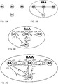
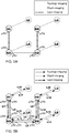
- Figures 2A, 2B, 2C and 2D depict the components of a physical network.
- Example physical nodes are shown in figure 2A and are considered physical resources onto which a logical network is created.
- the name of the physical node (BA through BD in figure 2A ) is only used to identify the physical resource and not used to make any forwarding decision upon.
- a physical network (identified with BAA in figure 2B ) as a collection of physical nodes. Physical nodes are interconnected by physical links (denoted by a solid line).
- a physical link In case a physical link is bidirectional, a physical link creates a pair of adjacencies between a pair of physical nodes, one adjacency in each direction. In case a physical link is unidirectional, a physical link creates a single adjacency between a pair of physical nodes.
- the physical link can be any physical medium, including but not limited to, fiber optic cable, copper cable, air.
- the physical link can also be a path provided by another networking technology, such as but not limited to an optical wavelength, a Time Division Multiplexing (TDM) circuit, a multi protocol label switching (MPLS) path.
- TDM Time Division Multiplexing
- MPLS multi protocol label switching
- the set of physical nodes combined with the set of physical links determines the physical topology of the network.
- the physical network can consist of an arbitrary number of nodes, with arbitrary links, resulting in an arbitrary topology.
- FIG. 2C A typical representation of a physical network is illustrated in figure 2C showing the physical network BAA and physical nodes BA through BD. As depicted in figure 2C , the interface between the physical node and the physical link is referred to as Physical 'Point-of-Attachment' (PoA), indicated by p101 to p108.
- PoA Physical 'Point-of-Attachment'
- a typical example of a Physical PoA identifier in currently deployed networks is an Ethernet Media Access Control (MAC) Address, but our invention is not limited to this.
- the PoA identifier has to be unique within the collection of networks that is under control of the SDN Compiler.
- each physical link has one or multiple cost types and a cost value(s) associated with each cost type in each direction.
- a typical cost type used in physical networks is the delay of the link, with cost values typically expressed in milliseconds, but any type of cost can be used, representing a property of said link.
- Each bidirectional physical link has 2 cost values, one for each direction.
- Each unidirectional physical link has 1 cost value for each cost type.
- the cost value of a physical link in a particular direction is shown closest to the physical node from which the packets originate for that particular direction.
- the link from BA to BB has a cost value of 1.
- the link from BB to BA has a cost value of 3.
- a physical link denotes the adjacency-relationship(s) between a pair of physical nodes
- a physical path denotes a physical route a packet or signal follows from a physical source node to a physical destination node, in case of unicast networking. In case of multicast or broadcast networking there are physical path relationships between a single physical source node and multiple physical destination nodes.
- Physical paths can have multiple cost types in each direction with typically a cost value equal to the sum of the cost values of that particular cost type in that particular direction of the physical links it consists of.
- a physical path is a sequence of physical PoAs through which the packet traverses from source node to destination node.
- Alternative terminology for a 'path' is a 'flow', e.g. the OpenFlow specification uses the terminology 'flow'.
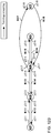
- the directed graph of network BAA is given in figure 2D , showing the vertices (nodes) BA through BD and the directed edges that connect pairs of vertices.
- an "edge" is indicated with an arrow connecting one vertex with another vertex where the direction of the arrow indicates the direction of flow of data.
- a bi-directional physical link between two vertices is represented by two edges. Each edge corresponds to an adjacency.
- PCT/EP2014/055640 pages 39, 41, 42 describes properties of a physical switch node, a physical host node, a physical NIC, a virtual switch node and a virtual host node in accordance with common usage of these terms.
- An example, but not limited to, a host node is Computing Equipment or a storage equipment (cf. PCT/EP2014/055640 pages 155 and 204).
- the logical network is defined by specifying:
- Cost types and values represent properties of links and can be used to determine a forwarding policy.
- the physical and/or virtual nodes as explained above are mapped to logical nodes using a 1:1, 1:N or N:1 mapping, as follows:
- mappings are represented as physical nodes in the method (cf. PCT/EP2014/055640 page 186), reducing above mappings to:
- the functional representation of a logical node is a dashed circle, as depicted in figure 3C .
- a physical/virtual to logical mapping can have an optional cost value for each direction of the mapping.
- the user of the SDN Compiler defines the logical network.
- the user could be, but is not limited to, a person, a network management system, a cloud management system, an application, another SDN Compiler.
- the logical network can consist of an arbitrary number of logical nodes, with arbitrary logical adjacencies, resulting in an arbitrary logical topology.
- the logical network could be specified as a graph in a high-level programming language, with the physical and/or virtual node(s) to which the logical node has been mapped being an attribute of each logical node.
- logical nodes For the logical nodes, we use a logical name space that is independent from the namespace of the physical and virtual resources.
- the logical network can now be defined in terms of logical node names, which may be expressed in any suitable form with any suitable number of unique characters and are mapped to the appropriate virtual and physical resources as required. By changing this mapping, the logical network can be re-mapped to other virtual and physical resources.
- 1:N physical to logical mapping allows for naming a single physical resource with multiple logical names.
- 1:N virtual to logical mapping allows for naming a single virtual resource with multiple logical names.
- the logical network is independent from the physical network and virtual resources, of course with the constraint a path exists between physical and virtual resources, and as such provides an abstraction of the physical network and virtual resources.
- a logical network As a collection of logical nodes Logical nodes are interconnected by logical links (denoted by a solid line). In case a logical link is bidirectional, a logical link creates a pair of adjacencies between a pair of logical nodes. In case a logical link is unidirectional, a logical link creates a single adjacency between a pair of physical nodes. The set of logical nodes combined with the set of logical links determines the logical topology of the network.
- a logical link denotes the adjacency-relationship(s) between a pair of logical nodes
- a logical path denotes a logical route a packet follows from a logical source node to a logical destination node, in case of unicast networking.
- a logical path is a sequence of physical PoAs and/or virtual PoAs through which the packet traverses from logical source node to logical destination node.
- a relationship between logical source and logical destination nodes and a path described in terms of physical and virtual PoA's This will allow us to define a network in logical node names and translate (compile) the defined network into instructions in terms of physical and/or virtual PoAs for the physical and/or virtual networking and/or computing resources.
- a logical network can be created from a physical network, a virtual network or a combined physical/virtual network (cf. PCT/EP2014/055640 page 93). Also, a logical network can be created from another logical network.
- a network at depth d created from a network at depth (d-1).
- d a particular depth as depth d, with d being a positive integer starting at 0 (zero).
- the combined physical and virtual network is consisting of one or more layers (cf.
- the physical link can be any physical medium, including but not limited to, fiber optic cable, copper cable, air.
- the physical link can also be a path provided by another networking technology, such as but not limited to an optical wavelength, a Time Division Multiplexing (TDM) circuit, a Multi Protocol Label Switching (MPLS) path.
- the virtual link can be a virtual connection, including but not limited to, virtual links between virtual switches and virtual machines, virtual links between virtual machines, network sockets.
- a layer might provide services to a higher layer and might consume services from a lower layer.
- the lowest packet-switching layer provides for Media-Access Control (MAC).
- MAC Media-Access Control
- a logical network is consisting of one or more layers.
- n n
- n_min n_min (d)
- layers in current networks are, but not limited to, physical medium layer, frequency- or wavelength-division multiplexing layer, time-division multiplexing layer, data link layer, network layer, transport layer, application layer.
- a layer n provides services to a layer (n+1) and a layer (n+1) consumes services provided by layer n.
- Each layer consists of an arbitrary number of sub-networks within a hierarchy of sub-networks with arbitrary number of hierarchy-levels.
- a network can be abstracted to a node and can become a node within another network.
- network BAA shown in figure 2C
- network BAA can be abstracted to a node in a network-of-networks.
- h_min(d, n) at depth d and layer n
- a network at level h_min(d, n) is a node. This applies to physical networks and logical networks. Using this terminology, physical network BAA at level h, shown in figure 2D , consists of physical network BA, BB, BC, BD at level (h-1).
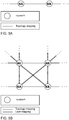
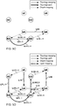
- FIG. 3A depicts networks KA and KB being at the same level h and being interconnected by a link.
- network KA and network KB could be interconnected to other networks as well.
- the relationships between networks are referred to as mappings.
- mappings In order to have a consistent naming for the various mappings that will be introduced hereafter, we will reference to a topology-mapping rather than an adjacency in the modeling of a link in the text below.
- a link is bi-directional, a link creates a pair of topology-mappings between a pair of networks.
- a topology-mapping is a mapping from a first network to a second network, the first and second network being at the same depth d and same layer n and same level h (cf. PCT/EP2014/055640 figure 49, page 179)
- Figure 3B depicts networks KA, KB, KC, KD being at the same level h.
- Networks KA and KB are interconnected by links, represented as a topology-mapping.
- Networks KA and KC are interconnected by links, represented as a layer-mapping.
- Networks KB and KC are interconnected by links, represented as a layer-mapping.
- a layer-mapping is a mapping from a first network to a second network, the first and second network being at different layers n.
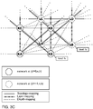
- networks KA, KB, KC, KD, LA, LB, LC, LD are shown.
- each network has the same level h.
- a network in figure 3C is equal to a 'network-of-nodes' referred to below
- a network in figure 3 is equal to a 'network-of-networks-of-nodes' referred to below
- Each network is situated at a particular depth d and layer n.
- networks KA and KB are at depth d
- layer n networks KC and KD are at depth d
- layer (n+1) networks LA and LB are at depth (d+1)
- layer n networks LC and LD are at depth (d+1), layer (n+1).
- the functional representation of a physical node is a circle with a solid circle, as depicted in figure 3A .
- the functional representation of a logical node is a dashed circle, as depicted in figure 3A .
- depth-mappings between network KA and network LD, between network KB and network LC, between network KC and network LB, between network KD and network LA are not shown to keep the figure relatively simple.
- topology-, layer- and depth-mappings are shown that are connected to only a single network KA, KB, KC, KD, LA, LB, LC or LD and are openended with '...' on the other side.
- layer-mappings illustrate that layer-mappings can be extended to an arbitrary number of layers.
- the depth-mappings connected to only a single network illustrate that depth-mappings can be extended to an arbitrary number of depths.
- the topology-mappings connected to only a single network at level h depict topology-mappings at level (h+1) as will be explained below.
- FIG. 3D shows networks KA, KB, KC, KD, LA, LB, LC, LD at level h and their topology-mapping, layer-mapping and depth-mapping relationships. Diagonal layer-mappings between nodes KA and KD, KB and KC, LA and LD, LB and LC which were shown in figure 3C have been omitted in this figure to simplify the figure.
- FIG. 3D also shows networks KAA, KCC, LAA, LCC at level (h+1).
- Network KAA at (d,n,h+1) contains networks KA and KB both at (d,n,h), in other words network KAA is mapped through a level-mapping to networks KA and KB.
- Network KCC at (d,n+1,h+1) contains networks KC and KD both at (d,n+1,h), in other words network KCC is mapped through a level-mapping to networks KC and KD.
- Network LAA at (d+1,n,h+1) contains networks LA and LB both at (d+1,n,h), in other words network LAA is mapped through a level-mapping to networks LA and LB.
- Network LCC at (d+1,n+1,h+1) contains networks LC and LD both at (d+1,n+1,h), in other words network LCC is mapped through a level-mapping to networks LC and LD.
- FIG. 4A shows network NAAA at (d, n, h+2) consisting of networks NAA, NCC and NEE at (d, n, h+1).
- Network NAA consists of networks NA and NB at (d, n, h).
- Network NCC consists of networks NC and ND at (d, n, h).
- Network NEE consists of networks NE and NF at (d, n, h).
- Figure 4A also shows the topology-mappings between networks at (d, n, h).
- a topology-mapping, layer-mapping, depth-mapping or level-mapping from a first network to a second network can be a 1:1, 1:N or N:1 mapping (first network : second network), (cf. PCT/EP2014/055640 page 96).
- Node is located by: 7-8 Network-of-Networks-of-Networks . Network-of-Networks . Network . Node
- a Network is located by: 7-8 Network-of-Networks-of-Networks . Network-of-Networks . Network-of-Networks .
- a NoNs is located by: 7-8 Network-of-Networks-of-Networks .
- each dot symbol ".” represents a level-mapping (cf. PCT/EP2014/055640 page 119), therefore the address structure follows exactly the hierarchical structure of a network as represented by level-mappings. Note that also within a physical network hierarchical naming can be used.
- An example but not limited to such a service is a multiplexing service.
- logical naming of various layers can be combined into a single logical address-space. This makes it possible to perform forwarding using a logical address-space spanning multiple layers. This provides a means to locate the node, through it's address, within a hierarchical network. Further, the above approach abstracts every network to a node at its particular level in the naming hierarchy.
- a NoNs is consisting of a collection of Networks with adjacencies between Networks, in the same way as a Network is consisting of a collection of Nodes with adjacencies between nodes.
- a topology-path is a concatenation of topology-mappings (cf. PCT/EP2014/055640 page 174).
- a first topology-path can comprise of a second topology-path, creating a nesting of the first topology-path and the second topology-path.
- a topology-path can be created using the following method: Calculating and storing a topology-path from a first network at (d, n, h) to a second network at (d, n, h) as a concatenation of zero or more topology-mappings at (d, n, h) and zero or more topology-paths at (d, n, h), said number of topology-mappings and said number of topology-paths being such that their sum is at least one.
- This method is referred to as the method to calculate a topology-path. (cf. PCT/EP2014/055640 pages 181,182).
- a concatenation of one topology-mapping refers to a situation in which said topology-path from a first network at (d, n, h) to a second network at (d, n, h) comprises of a single topology-mapping.
- the term 'a concatenation of one' is used to avoid the or-statement in order to keep the description relatively simple.
- a first level-path can comprise of a second level-path, creating a nesting of the first level-path and the second level-path (cf. PCT/EP2014/055640 page 174).
- a level-path can be created using the following method: Calculating and storing a level-path from a first network at (d, n, h1) to a second network at (d, n, h2) as a concatenation of zero or more level-mappings at (d, n) and zero or more level-paths at (d, n), said number of level-mappings and said number of level-paths being such that their sum is at least one.
- This method is referred to as the method to calculate a level-path.
- topology-paths and one or more level-paths can be concatenated, we refer to a topology-level-path from a first network at (d, n, h1) to a second network at (d, n, h2) as a concatenation of zero or more topology-paths at (d, n) and zero or more level-paths at (d, n) and zero or more topology-level-paths at (d, n), said number of topology-paths and said number of level-paths and said number of topology-level-paths being such that their sum is at least one.
- This method is referred to as the method to calculate a topology-level-path..
- a first topology-level-path can comprise of a second topology-level-path, creating a nesting of the first topology-level-path and the second topology-level-path.
- a topology-level-path can be a single topology-path or can be a single level-path.
- a requested topology-path could be requested by an SDN Controller, a physical node, a user of the SDN Compiler. Such request could be a proactive path-instantiation or a reactive path-instantiation.
- a topology-mapping, depth-mapping, layer-mapping, level-mapping, topology-path, level-path and topology-level-path as an edge.
- topology-level-path can comprise of a single topology-path, a single level-path, a single topology-mapping or a single level-mapping.
- a topology-mapping can be created using any of the following methods:
- the topology-level-path used in the first method and second method to calculate a topology-mapping can be a topology-level-path, a topology-path or a level-path, as a topology-level-path can comprise of a single topology-path and a topology-level-path can comprise of a single level-path.
- the topology-level-path used in the calculation of the topology-mapping can either a topology-level-path that is explicitly created or can be concatenation of topology-mappings and level-mappings.
- a layer-mapping can be created using any of the following methods:
- the third and fourth network can be the same network at (d-x, n2, h) or at (d-x, n2-y, h).
- the third and fourth network can be the same network at (d-x, n2, h) or at (d-x, n2+y, h).
- a layer-mapping from a first node at layer n to a second node at layer (n-1) followed by a topology-mapping results in a multiplexing action, such as for example but not limited to in node KA (cf. PCT/EP2014/055640 page 236).
- the SDN Compiler should be aware of the multiplexing and de-multiplexing capabilities of physical nodes when providing forwarding entries on component level rather than equipment level.
- the multiplexing and de-multiplexing capabilities could be provided to the SDN Compiler by an Element Management System (EMS).
- EMS Element Management System
- Figure 6A shows the notation used for a first mapping with a first edge name, the first mapping being of a first mapping-type, the first mapping-type being a topology-mapping, depth-mapping, layer-mapping or level-mapping from a first network to a second network.
- the first PoA and the second PoA are optional.
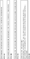
- FIG. 5A shows networks KA, KB, KC, KD, LA, LB, LC, LD, as shown in figure 3C above and a topology-mapping between network KA and network KB, a layer-mapping between network KA and network KC and a layer-mapping between network KB and network KD.
- Figure 5A also shows Point-of-Attachments (PoAs) p701 through p706.
- PoAs Point-of-Attachments
- networks KA, KB, KC and KD are physical networks
- the topology-mapping between network KA and network KB is representing a physical link
- the layer-mapping between network KA and network KC is representing a physical link
- the layer-mapping between network KB and network KD is representing a physical link.
- a physical link can be uni-directional or bi-directional we represent a topology-mapping, depth-mapping, layer-mapping, level-mapping, topology-path, level-path or topology-level-path from a first network to a second network by a directed edge in a graph.
- FIG. 5B shows networks KA, KB, KC, KD, LA, LB, LC, LD, topology-mappings, layer-mappings and depth-mappings.
- Figure 7A shows the mappings of figure 5B in the notation of figure 6A .
- 'depmap' refers to 'depth-mapping'
- 'laymap' refers to 'layer-mapping'
- 'levmap' refers to 'level-mapping'
- 'toppath' refers to 'topology-path'
- 'levpath' refers to 'level-path' in the notation used.
- the direction of a depth-mapping, a layer-mapping and a level-mapping can be included in the mapping type (cf. PCT/EP2014/055640 page 180).
- figure 6B shows a second mapping with a second edge-name, the second mapping being of a second mapping-type from the second network to a third network.
- figure 5C by applying the first method for calculating a topology-mapping described above, we calculate and store a topology-mapping named L14 from network LA to network LB as a concatenation of a depth-mapping named L12 from network LA to network KA, a topology-path named L11 from network KA network KB and a depth-mapping named L13 from network KB to network LB, the topology-path named L11 from network KA to network KB comprising of a single topology-mapping named L5 from network KA to network KB.
- topology-path named L11 could also have been omitted and the topology-mapping named L14 could have been created from topology-mapping L5 directly.
- the topology-mapping named L5 from network KA to network KB is labeled with L5/L11 indicating that topology-mapping L5 is used to calculate topology-path L11 or in other words that topology-path L11 is mapped to topology-mapping L5.
- edge-relationship a relationship between two edges as an edge-relationship, in which a second edge is multiplexed or mapped to a first edge and we represent such edge-relationship by "first edge / second edge", using a forward-slash symbol.
- L5/L11 as shown in figure 5C as an edge-relationship between a topology-mapping indicated by edge name L5 and a topology-path indicated by edge name L11, in which topology-path named L11 is mapped to topology-mapping named L5, or in other words, in which topology-mapping L5 is used to calculate topology-path L11.
- L5/L11 an edge-relationship between a topology-mapping indicated by edge name L5 and a topology-path indicated by edge name L11, in which topology-path named L11 is mapped to topology-mapping named L5, or in other words, in which topology-mapping L5 is used to calculate topology-path L11.
- Figure 6C shows the notation of a third edge with a third edge-name, the third edge being of a third edge-type and being concatenation of a first edge and a second edge, the plus symbol indicating the concatenation and the forward-slash symbol representing an edge-relationship.
- a topology-mapping named L22 from network LC to network LD as a concatenation of a layer-mapping named L19 from network LC to network LA, a topology-path named L21 from network LA network LB and a layer-mapping named L20 from network LB to network LD, the topology-path named L21 from network LA to network LB comprising of a single topology-mapping named L14 from network LA to network LB.
- Figure 7B shows the creation of topology-paths L11, L21 and L23, topology-mappings L14 and L22 and layer-mappings L19 and L20 using the notation of figure 6C .
- the edge-relationships shown in figure 5F can be used to calculate a set of edge-relationships through recursion.
- recursion refers to a mathematical recursion operation.
- Said set of edge-relationships comprises of nested edge-relationships.
- the term “nested” in “nested edge-relationship” refers to edge-relations having a mathematically nested format.
- the topology-mapping from network KA to network KB has edge-relationship L5/L11
- the topology-path from network KA to network KB has edge-relationship L11/L14
- the topology-mapping from network LA to network LB has edge-relationship L14/L21
- the topology-path from network LA to network LB has edge-relationship L21/L22
- the topology-mapping from network LC to network LD has edge-relationship L22/L23
- the topology-path from network LC to network LD has name L23
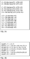
- the topology-mapping named L11 from network KA to network KB has an example set of edge-relationships L5/L11/L14/L21/L22/L23.
- L5 L5/L11/L14/L21/L22/L23.
- L5 L5/L14/L23.
- the first edge name in a set of edge-relationships is the name of said edge.
- a recursive-path is defined as a path that is calculated using recursion as a mathematical technique.
- An example of a recursive-path is L23 in Figure 5F .
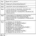
- Figure 7C illustrates the calculation of a recursive-path of the topology-path named L23 from network LC to network LD.
- L23 the single topology-mapping named L22 from network LC to network LD
- L23 the topology-path named L23 in figure 7B
- toppath L23 L22/L23
- Steps 2 through 4 of figure 7C are intermediate steps in the calculation.
- a notation for a topology-path, level-path or topology-level-path is shown, using the notations of figures 6A, 6B and 6C .
- step 6 of figure 7C the recursive-path of step 5 is shown using the notation of figure 6D by combining step 5 of figure 7C with figure 7A .
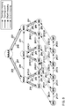
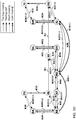
- each a level-mapping of figure 4B being a relationship between a first network at level h and a second network at level h+1, such as but not limited to, the level-mapping between network NAA and network NAAA, is represented by a pair of level-mappings being directed edges, such as but not limited to, a level-mapping from network NAA to network NAAA and a level-mapping from network NAAA to network NAA.
- the level-mapping from network NAA to network NAAA is named J22 and is shown in figure 8 .
- the level-mapping from network NAAA to network NAA is named J47 and is shown in figure 8 .
- PCT/EP2014/055640 (figure 53E) describes physical topology-mappings, depth-mappings and level-mappings, per the notation of figure 6A .
- FIG 8 we calculate and store a topology-mapping named J30 from network NAA to network NCC as a concatenation of a level-mapping named J17 from network NAA to network NB, a topology-path named J29 from network NB network NC and a level-mapping named J18 from network NC to network NCC, the topology-path named J29 from network NB to network NC comprising of a single topology-mapping named J25 from network NB to network NC, using the third method for calculating topology-mappings described above.
- topology-mapping named J31 From network NCC to network NEE as a concatenation of a level-mapping named J19 from network NCC to network ND, a topology-mapping named J27 from network ND network NE and a level-mapping named J20 from network NE to network NEE, using the third method for calculating topology-mappings described above.
- By creating the topology-mappings named J30 and J31 we can specify forwarding behavior between networks-of-nodes NAA, NCC and NEE.
- the creation of topology-mappings can be repeated at arbitrary number of hierarchy levels.
- PCT/EP2014/055640 pages 213) describes how a level-path is changed to a topology-path.
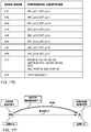
- PSN Packet Switched Network
- a switching-identifier depends on the depth d and layer n in which a topology is created comprising of networks and topology-mappings.
- Networks at a particular depth d and layer n are either all packet-switched networks or all non-packet-switched-networks.
- Nodes at a particular depth d and layer n are either all packet-switched nodes or all non-packet-switched-nodes.
- PCT/EP2014/055640 (pages 189 through 192) describes examples of switching-identifiers of type i), type ii) and type iii).
- layer n the SDN Compiler should be instructed by a user, such as for example, but not limited to a network administrator (cf. PCT/EP2014/055640 page 191):
- the information at i) above is used by the SDN Compiler to select the method for creation of forwarding entries for a physical packet-switching node or of forwarding entries for a physical non-packet-switching node.
- the recursive-path also contains:
- forwarding entries for physical nodes also referred to as forwarding instructions
- forwarding entries for physical nodes also referred to as forwarding instructions
- Forwarding entries for each physical node in the recursive-path comprise of an input port, an output port, the switching-identifiers of incoming set of edge-relationships and the switching-identifiers of outgoing set of edge-relationships.
- Above forwarding entries are send to the physical nodes in the recursive-path, either directly or indirectly, as an example but not limited to, through an SDN Controller.
- PCT/EP2014/055640 (page 197) describes that for a node the number of edges within a set of incoming edge-relationships may be reduced by determining a relevant incoming set of edge-relationships.
- the relevant incoming set of edge-relationships are the set of edge-relationships of an incoming topology-mapping or an incoming layer-mapping at depth, layer, level of said node and at depth, layer, level of all networks in the recursive-path mapped to said node through one or more depth-mappings.
- PCT/EP2014/055640 (page 197) describes that for a node the number of edges within a set of outgoing edge-relationships may be reduced by determining a relevant outgoing set of edge-relationships.
- the relevant outgoing set of edge-relationships are the set of edge-relationships of an outgoing topology-mapping or an outgoing layer-mapping at depth, layer, level of said node and at depth, layer, level of all networks in the recursive-path mapped to said node through one or more depth-mappings.
- a physical node in a Packet-Switching Network (PSN) and a physical node in a non-PSN.
- a physical node in a PSN referred to as a physical packet-switching node, performs forwarding and statistical multiplexing of packets.
- a physical node in a non-PSN referred to as physical non-packet-switching node, performs relaying and multiplexing of physical signals.
- An example, but not limited to, of a non-PSN is a Circuit-Switching Node (CSN).
- An example, but not limited to, of a non-PSN is a node in a wireless network performing multiplexing of physical signals.
- CSN Circuit-Switching Node
- PCT/EP2014/055640 (pages 193 and 194) describes the calculation of forwarding entries for a physical packet-switching node.
- PCT/EP2014/055640 (pages 195 and 196) describes the calculation of forwarding entries for a physical non-packet-switching node.
- PCT/EP2014/055640 (pages 198 through 200) describes the creation of a single forwarding entry for a physical equipment comprising of two or more physical nodes.
- topology-mapping, layer-mapping, topology-path, level-path or topology-level-path per above described method, optionally one or more requirements are taken into account when creating said topology-mapping, layer-mapping, topology-path, level-path or topology-level-path (cf. PCT/EP2014/055640 page 221). Only if said topology-mapping, layer-mapping, topology-path, level-path or topology-level-path complies with said one or more requirements, said topology-mapping, layer-mapping, topology-path, level-path or topology-level-path is created.
- a topology-mapping, layer-mapping, topology-path, level-path or topology-level-path is only created when requirements for said topology-mapping, layer-mapping, topology-path, level-path or topology-level-path are met by the calculated said topology-mapping, layer-mapping, topology-path, level-path or topology-level-path.
- a requested topology-path, level-path or topology-level-path can be considered as a service for a user (cf. PCT/EP2014/055640 page 222). An example, but not limited to, of said user being a person, an organization, an application.
- the requirements of said service are stored in a contract, being a Service-Level-Agreement (SLA) between said user and the provider of said service.
- SLA Service-Level-Agreement
- the above method allows said provider of said service to offer much richer services, based on said more complex requirements that can be used when establishing said service.
- Edge-relationships are used to determine the impact of any changes in a set of networks. As an example, but not limited to, as shown in figure 50C the topology-mapping named L5 from network KA to network KB is with edge-relationship L5/L11, therefore if the first edge named L5 is changed, the second edge named L11 is impacted.
- the topology-mapping named L5 is deleted, for example but not limited to, the topology-mapping L5 being a physical fiber link which is cut, the topology-mapping named L11 is impacted, as per the edge-relationship L5/L11, and will have to be recalculated by the SDN Compiler.
- the topology-path L23 is a requested topology-path and the topology-path named L23 can not be recalculated, as in the example of figure 50F, the Service-Level-Agreement (SLA) of said requested topology-path is violated.
- SLA Service-Level-Agreement
- the described method allows for multi-layer survivability in a set of networks. Also, note that the described method allows for a much deeper analysis of SLA's. As an example but not limited to a large number of failure scenario's could be simulated from the information stored by the method and the impact on one or more SLA's could be determined. As an example but not limited to this allows for checking SLA violation probability versus incurred penalties of said SLA violation. Note that the described method allows for storing each SLA violation, therefore building a record for said SLA.
- a forwarding entry in case of a non-packet-switching network is an instruction specifying how an incoming signal at an input port should be relayed to an output port after optional modification of said incoming signal.
- the SDN Compiler creates an instruction specifying how an incoming wavelength at an input port should be relayed, also referred to as cross-connected, to an output port after optional modification of said incoming wavelength, such as for example changing the frequency of the incoming wavelength.
- Forwarding entries are send to the physical nodes in the recursive-path, either directly or indirectly, as an example but not limited to, through an SDN Controller.
- the method described can be implemented using a graph database, wherein networks, mappings, topology-paths, level-paths and topology-level-paths are stored in a graph database, wherein a network is stored as a named vertex in a graph database, wherein a mapping, being a topology-mapping, depth-mapping, layer-mapping or level-mapping is stored as a named and directed edge in a graph database, wherein a topology-path, level-path or topology-level-path is stored as a named and directed edge in a graph database, wherein properties of said networks are stored as vertex attributes in said graph database, wherein properties of said mappings are stored as edge attributes in said graph database, wherein properties of said topology-paths, level-paths or topology-level-paths are stored as edge attributes in said graph database (cf.
- the type of mapping and the direction of said mapping can be stored as an edge type in said graph database.
- the type of topology-level-path being a topology-path, level-path or topology-level-path can be stored as an edge type in said graph database.
- An example of a type of mapping and a direction of said mapping is an increasing depth-mapping.
- a graph database supporting more than one edge type is typically referred to as a graph database supporting property graphs.
- a graph database is typically, but not limited to, based on a property graph model consisting of vertices having properties and directed edges having properties.
- the network properties within the SDN Compiler method can be stored as vertex properties.
- vertex properties also referred to as vertex attributes
- vertex attributes could comprise the network-related inputs of the SDN Compiler method described above as well as additional network information such as for example but not limited to geographic longitude of the physical or virtual node, geographic latitude of the physical or virtual node and uptime of the node.
- the topology-mapping, layer-mapping and depth-mapping properties within the SDN Compiler method can be stored as edge properties.
- the first method to calculate a topology-mapping, the second method to calculate a topology-mapping, the third method to calculate a topology-mapping, the first method to calculate a layer-mapping, the second method to calculate a layer-mapping, the method to calculate a topology-path, the method to calculate a level-path and the method to calculate a topology-level-path, used to create or recalculate a mapping or a topology-path, level-path or topology-level-path, can be implemented as a query in a graph database. Additional requirements as described above can be included in such query.
- a query of the first method to calculate a topology-mapping could be a graph database query for a path from a first node to a second node matching a depth-mapping decreasing in depth from said first node to a third node, matching a depth-mapping increasing in depth from a fourth node to said second node, matching a topology-path from said third node to a fourth node.
- additional requirements could be specified in said example query.
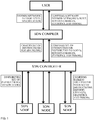
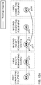
- FIG. 9 shows the USER of the SDN Compiler, one ore more SDN Controllers and one or more physical SDN nodes. All information of the networks, topology-mappings, depth-mappings, layer-mappings, level-mappings, topology-paths, level-paths, topology-level-paths in stored in a database.
- An example, but not limited to, such a database is a graph database.
- the event handler handles all incoming events from the USER, one or more SDN Controllers and from the database.
- the database could directly query itself, but to allow for event-handling and prioritization database requests from to database to the database flow through the event-handler.
- the event-handler allows for event prioritization and protects the database from query attacks.
- the instructor is responsible for creating forwarding entries for a user-requested topology-path, level-path or topology-level-path after this topology-path, level-path or topology-level-path is created in the database.
- One or more SDN controllers can send requests to the event handler. Alternatively, an additional monitor could be used that polls one or more SDN Controllers.
- a forwarding entry in case of a non-packet-switching network is an instruction specifying how an incoming signal at an input port should be relayed to an output port after optional modification of said incoming signal.
- one or more topology-mappings can be created using the second method to create topology-mappings
- forwarding entries can be calculated using the method to calculate forwarding entries for non-packet-switching nodes
- edges can be recalculated
- a service can be requested in accordance with a set of requirements.
- the above method can be implemented using a graph database.
- PCT/EP2014/055640 (pages 207 through 211, figure 52N) describes that as an alternative to creating logical nodes, a logical name can be assigned to a physical node and/or a physical topology-mapping and/or a physical PoA.
- PCT/EP2014/055640 (pages 234 through 240, figure 59B) describes an example of a non packet-switching network, with or without logical nodes.
- the network at the highest hierarchy level in the namespace for each tenant should be globally unique to ensure isolation from other tenants.
- the highest hierarchy level could be an IPv6 flow label or could be an IPv4 identification field repurposed to denote a tenant.
- much more complex topologies are supported by the SDN Compiler than the relatively simple topologies used in the examples above used to describe the SDN Compiler method.
- various methods described above fall with the scope of the present invention, such as for example but not limited to, multicasting, tunneling, label-switching.
- the SDN Compiler method described in PCT/EP2014/055640 is extended to determine depth-mappings, relating nodes at different depths, by an SDN Compiler based on requirements of logical nodes, logical-topology-mappings, and optionally logical layer-mappings, specified by a user of an SDN Compiler.
- Said extension allows a user of an SDN Compiler to specify logical nodes, requirements of logical nodes, logical topology-mappings and requirements of logical topology-mappings, and optionally logical layer-mappings and requirements of logical layer-mappings and have said SDN Compiler determine physical and/or virtual resources, comprising of physical nodes and physical links, against which said logical specification can be compiled, thereby determining the relationships between logical nodes and physical nodes as represented by depth-mappings, physical topology-paths, and optionally physical layer-mappings.
- a user of an SDN Compiler could specify a first logical node denoting logical compute and a second logical node denoting logical compute and a topology-mapping from said first logical node to said second logical node, and nodes, topology-mappings and layer-mappings at one or more lower layers and have said SDN Compiler determine physical and/or virtual resources against which said logical specification can be compiled, thereby determining the relationships between logical nodes and physical nodes as represented by depth-mappings, physical topology-paths, and optionally physical layer-mappings.
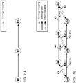
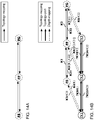
- FIG. 11A shows three logical nodes named FE, FF and FG as shown in figure 11A .
- Logical nodes FE and FG are logical host nodes and logical node FF is a logical switch node.
- Figure 11A also shows a topology-mapping from logical node FE to logical node FF and a topology-mapping from logical node FF to logical node FG, represented as directed edges in a graph.
- a user of an SDN Compiler would specify the logical nodes FE, FF and FG and the topology-mappings shown in figure 11A .
- known physical nodes and "unknown physical nodes”.
- logical nodes can be mapped to "known” and/or “unknown” physical nodes through depth-mappings.
- known physical nodes are "physical nodes” which are existing or still to be setup (virtual) nodes in the network and of which the physical node names are stored in one or more databases which are directly or indirectly accessible to the compiler. Below, the label “known” will not always be used if the context does not require so.
- unknown physical node is used to define an imaginary physical node to which logical nodes can be mapped through depth-mappings and which are to be substituted by a physical node of the network of which the physical node name is stored in said database(s).
- Such unknown physical nodes can advantageously be used in a method of building the network model in case of cloud computing, as will be explained in more detail below.
- known physical topology-paths and "unknown physical topology-paths".
- known physical topology-paths are "physical topology-paths" which are existing or still to be setup topology-paths in the network between two physical nodes and of which the physical topology-path names are stored or to be stored in one or more databases which are directly or indirectly accessible to the compiler.
- known will not always be used if the context does not require so.
- unknown physical topology-path is used to define an imaginary physical topology-path between either two "unknown physical nodes” or between one "unknown physical node” and a "known physical node”.
- Such an "unknown physical topology-path" is to be substituted by a physical topology-path of the network of which the physical topology-path name is stored or to be stored in said database(s), said physical topology-path being a concatenation of one or more existing or still to be setup physical topology-mappings.
- Such unknown physical topology-paths can advantageously be used in a method of building the network model, as will be explained in more detail below.
- known physical layer-mapping and "unknown physical layer-mapping”.
- known physical layer-mappings are "physical layer-mappings" which are existing or still to be setup layer-mappings in the network between two physical nodes and of which the physical layer-mapping names are stored in one or more databases which are directly or indirectly accessible to the compiler.
- known will not always be used if the context does not require so.
- unknown physical layer-mapping is used to define an imaginary physical layer-mapping between either two "unknown physical nodes” or between one "unknown physical node” and a "known physical node”.
- Such an "unknown physical layer-mapping" is not (yet) linked to a physical layer-mapping of which the physical layer-mapping name is stored in said database(s).
- Such unknown physical layer-mappings can advantageously be used in a method of building the network model, as will be explained in more detail below.
- known/unknown physical node refers to a set comprising all known and unknown physical nodes and each member of this set may either be a known or an unknown physical node.
- known/unknown physical node names are names of these "known/unknown physical nodes”.
- the term “known/unknown physical topology-path” is used. This latter term refers to a set comprising all known and unknown physical topology-paths and each member of this set may either be a known or an unknown physical topology-path. "Known/unknown physical topology-path names” are names of these "known/unknown physical topology-paths”.
- an unknown physical node at (d-x, n2, h2) can be created with x being larger than zero and smaller than or equal to d, where n1 may be equal to n2 and where h1 may be equal to h2.
- a depth-mapping named K3 is created from unknown physical node ?X1 to logical node FE
- a depth-mapping named K4 is created from logical node FE to unknown physical node ?X1
- a depth-mapping named K5 is created from unknown physical node ?X2 to logical node FF
- a depth-mapping named K6 is created from logical node FF to unknown physical node ?X2
- a depth-mapping named K7 is created from unknown physical node ?X3 to logical node FG
- a depth-mapping named K8 is created from logical node FG to unknown physical node ?X3.
- Figure 11B shows depth-mappings named K3 through K8.
- Figure 11C shows depth-mappings named K3 through K8, per the notation of figure 6A . Therefore, actions a) and b) for the above described example is:
- a topology-mapping named K1 is created using the first method to calculate a topology-mapping, comprising of a concatenation of the depth-mapping named K4, an unknown topology-path named ?K9 and the depth-mapping named K5, as shown in figure 11B .
- the questions mark before K9 in "?K9/K1" indicates that K9 is an unknown physical topology-path. Note that the unknown physical topology-path named ?K9 is created and stored during this step.
- a topology-mapping named K2 is created using the first method to calculate a topology-mapping, comprising of a concatenation of the depth-mapping named K6, an unknown topology-path named ?K10 and the depth-mapping named K7, as shown in figure 11B .
- the questions mark before K10 in "?K10/K2" indicates that K10 is an unknown physical topology-path.
- the unknown physical topology-path named ?K10 is created and stored during this step.
- Figure 11D shows topology-mappings K1 and K2, as described above, per the notation of figure 6C .
- action c) for the above described example is: c) Creating and storing one or more logical topology-mappings (K1; K2), each logical topology-mapping (K1; K2) being a directed graph representation from a first logical node (FE; FF) to a second logical node (FF; FG), calculated as a concatenation of a first depth-mapping (K4; K6) from the first logical node (FE; FF) to a first known/unknown physical node (?X1; ?X2), a known/unknown physical topology-path (?K9; ?K10) from the first known/unknown physical node (?X1; ?X2), to a second known/unknown physical node (?X2; ?X3), and a second depth-mapping (K1; K2), each logical topology-mapping (K1; K2) being a directed graph representation from a first logical node (FE;
- Step 1) of figure 11E shows the topology-mapping named K1 per figure 11D .
- step 2) of figure 11E the values of the depth-mappings named K4 and K5 in step 1) of figure 11E have been replaced by the definition of the depth-mappings named K4 and K5 shown in figure 11C .
- the topology-mapping named K1 comprises logical nodes named FE and FF, depth-mappings named K4 and K5, zero physical nodes, two unknown physical nodes named ?X1 and ?X2, one unknown physical topology-path named ?K9, zero physical topology-mappings, and zero physical point-of-attachments.
- Step 1) of figure 11F shows the topology-mapping named K2 per figure 11D .
- step 2) of figure 11F the values of the depth-mappings named K6 and K7 in step 1) of figure 11F have been replaced by the definition of the depth-mappings named K6 and K7 shown in figure 11C .
- topology-mapping named K2 comprises logical nodes named FF and FG, depth-mappings named K6 and K7, zero physical nodes, two unknown physical nodes named ?X2 and ?X3, one unknown physical topology-path named ?K10, zero physical topology-mappings, and zero physical point-of-attachments.
- said third search statement comprises a 'logical AND' of said first search statement and said second search statement as the objective of said search is to determine a physical node for each unknown physical node and a physical topology-path for each unknown physical topology-path, in accordance with the logical nodes and logical topology-mappings defined by the user of the SDN Compiler.
- said search statement comprises of physical entities including nodes and topology-paths which comprise of topology-mappings being links in a single direction (including wireless links) and their relationships from multiple recursive paths, in this example unknown physical nodes ?X1, ?X2 and ?X3, and unknown physical topology-paths named ?K9 and ?K10.
- Said search is performed against a physical network layout comprising of physical nodes being interconnected by physical topology-mappings, said physical topology-mapping being based on a directed graph representation, as is described below.
- PCT/EP2014/055640 (page 230) describes that the first method to calculate a topology-mapping, the second method to calculate a topology-mapping, the third method to calculate a topology-mapping, the fourth method to calculate a topology-mapping, the fifth method to calculate a topology-mapping, the first method to calculate a layer-mapping, the second method to calculate a layer-mapping, the method to calculate a topology-path, the method to calculate a level-path and the method to calculate a topology-level-path, used to create or recalculate a mapping or a topology-path, level-path or topology-level-path, can be implemented as a query in a graph database. Additional requirements as described above can be included in such query. As an example, but not limited to, said third search statement described above can be implemented as a query in a graph database.
- requirements can be taken into account.
- above requirements of said logical topology-mappings might be stored.
- said requirements of each of said logical topology-mappings might be copied to said unknown physical topology-path used in the calculation of said logical topology-mapping, and said requirements of each of said unknown physical topology-paths might be matched with properties of a physical topology-path in said search, said properties of said physical topology-path being determined by properties of physical topology-mappings from which said physical topology-path is calculated.
- a requirement of the logical topology-mapping named K1 to be 'Requirement A' and store 'Requirement A' at action c) above as a requirement of the topology-mapping named K1.
- the requirement of the logical topology-mapping named K1 is copied to the unknown physical topology-path named ?K9 used in the calculation of the logical topology-mapping K1, as per the edge-relationships '?K9/K1' as shown in figure 11D , and the requirement of the unknown physical topology-path named ?K9, being 'Requirement A' is matched with properties of a physical topology-path in said search.
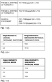
- Figure 11H shows how requirements of the logical topology-mapping named K1 are related to requirements of the unknown physical topology-path named ?K9 per the edge-relationship '?K9/K1' as shown in figure 11D .
- Figure 11H also shows how requirements of the logical topology-mapping named K2 are related to requirements of the unknown physical topology-path named ?K10 per the edge-relationship '7K10/K2' as shown in figure 11D .
- a requirement of the logical node FE to be 'type host' and store 'type host' at action b) above as a requirement of the logical node named FE, as logical node FE is a host node.
- the requirement of logical node FE is copied to the unknown physical node name ?X1 mapped to the logical node FE through the depth-mapping named K4 in the topology-mapping named K1, as shown in figure 11E , and said requirements of each of said unknown physical nodes might be matched with properties of said physical node in said search.
- Figure 11I shows how requirements of the logical node named FE are related to requirements of the unknown physical node named ?X1 per the depth-mapping named K4 in the topology-mapping named K1, as shown in figure 11E .
- Figure 11I shows how requirements of the logical node named FF are related to requirements of the unknown physical node named ?X2 per the depth-mapping named K5 in the topology-mapping named K1, as shown in figure 11E , and per the depth-mapping named K6 in the topology-mapping named K2, as shown in figure 11F .
- Figure 11I shows how requirements of the logical node named FG are related to requirements of the unknown physical node named ?X3 per the depth-mapping named K7 in the topology-mapping named K2, as shown in figure 11F .
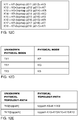
- Typical properties of a physical node include, but are not limited to:
- Typical properties of a physical link include, but are not limited to:
- the properties of a physical topology-mapping are the properties of a physical link in one direction.
- said properties of a physical topology-mapping determine the properties of a physical topology-path, said physical topology-path being a concatenation of zero or more physical topology-mappings and zero or more physical topology-paths, said number of topology-mappings and said number of topology-paths being such that their sum is at least one.
- Typical requirement of a logical node include, but are not limited to:
- Typical properties of a logical topology-mapping include, but are not limited to:
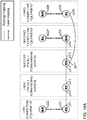
- FIG. 12A shows a first computing equipment, represented by physical node KP, a first packet forwarding system, represented by physical node KQ, a second packet forwarding system, represented by physical node KR, a second computing equipment, represented by physical node KS, and a third computing equipment, represented by physical node KT, connected by topology-mappings being physical links.
- Figure 12A also shows Point-of-Attachment (PoA) p211 through p218.
- PoA Point-of-Attachment
- Figure 12B also shows topology-mappings named K11 through K18, represented as directed edges in a graph.
- Figure 12C shows topology-mappings named K11 through K18, per the notation of figure 6A .
- KP, KS and KT represent a first, second and third computing equipment respectively
- KQ and KR represent a first and second packet forwarding system respectively
- KQ and KR represent a first and second packet forwarding system respectively
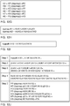
- search statement can be reduced to "(?X1-?K9[toppath]->?X2) AND (?X2-?K10[toppath] ->?X3)", omitting "/K1" and "/K2".
- the search statement including requirements is, written in pseudo-code:
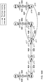
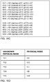
- Figure 12D shows how unknown physical node ?X1 is matched against physical node KP, unknown physical node ?X2 is matched against physical node KQ, and unknown physical node ?X3 is matched against physical node KS.
- Figure 12E shows how the unknown physical topology-path named ?K9 is matched against a physical topology-path, which is named K9 for consistency, comprising of the physical topology-mapping named K11, as shown in figure 12E per the notation of figure 6C .
- Figure 12E shows how the unknown physical topology-path named ?K10 is matched against a physical topology-path, which is named K10 for consistency, comprising of a concatenation of physical topology-mappings named K13 and K15, as shown in figure 12E per the notation of figure 6C .
- Per action d) above we replace and store each unknown physical topology-path by a physical topology-path, said physical topology-path being a concatenation of one or more physical topology-mappings, and we replace each unknown physical node by a physical node in accordance with a result of said search.
- the depth-mappings named K3 through K8 have become depth-mappings between logical nodes FE, FF, FG and physical nodes KP, KQ, KR respectively as shown in figure 12G , in comparison to figure 11C in which the depth-mappings named K3 through K8 were depth-mappings between logical nodes FE, FF, FG and unknown physical nodes ?X1, ?X2, ?X3.
- FIG 12F This is illustrated in figure 12F .
- Figure 12F also shows topology-mappings named K1, K2, K11 through K18, depth-mappings named K3 through K8, physical topology-paths named K9 and K10, and a logical topology-path named K19, represented as directed edges in a graph.
- action d) for the above described example is: d) Determining a suitable physical node (KP; KQ; KS) in the overall network for each unknown physical node (?X1; ?X2; ?X3) and determining a suitable physical topology-path (K9; K10) in the overall network for each unknown physical topology-path (?K9; ?K10) by performing a search comprising matching each unknown physical topology-path (?K9; ?K10) with one of a set of suitable physical topology-paths, and matching each unknown physical node with one (KP; KQ; KS) of a set of suitable physical nodes, and replacing and storing each unknown physical topology-path (?K9; ?K10) by said one of said set of suitable physical topology-paths (K9; K10), said one of said suitable physical topology-paths (K9; K10) being a concatenation of one or more physical topology-mappings (K11; K13, K15), and replacing
- K19 being a concatenation of topology-mappings K1 and K2 as shown in figure 12F and as shown in figure 12I per the notation of figure 6C .
- the recursive-path of the topology-path named K19 contains the following information for each physical network in said recursive-path, being physical nodes KP, KQ, KR and KS:
- above input port, output port, a set of incoming edge-relationships, and a set of outgoing edge-relationships is the information contained in the topology-mappings named K11, K13 and K15.
- the combination of above input port, output port, a set of incoming edge-relationships, a set of outgoing edge-relationships, and switching-identifiers of incoming set of edge-relationships and switching-identifiers of outgoing set of edge-relationships results in forwarding entries for physical nodes KP, KQ, KR and KS.
- the switching-identifiers for edges K11 through K19 are shown in figure 12K .
- the switching-identifiers of edges K11 through K18 denote physical PoA's at the datalink layer, performing Media Access Control (MAC).
- the switching-identifier of the edge named K19 is "Source FE, Destination FG", using the name of the source node FE of the topology-path named K19 as source and using the name of the destination node FG of the topology-path named K19 as destination.
- no depth-mappings were specified between a logical node and a physical node.
- a user of an SDN Compiler might specify one or more depth-mappings between a logical node and a physical node, which would result in a search statement that might include said physical node used in the search at action d) above.
- a logical node might be mapped to a physical node through a depth-mapping when said physical node is known to provide connectivity to other networks, also known as a gateway.
- Figures 13A through 13E show an example to which the above described method is applied with a single depth-mapping from a logical node to a physical node being known.
- Figure 13A shows logical node FE, logical node FF, logical node FG, as per figure 11A .
- Figure 13A also shows a topology-mapping from logical node FE to logical node FF, a topology-mapping from logical node FF to logical node FG, as per figure 11A .
- Figure 13A also shows a physical node KP and a depth-mapping from logical node FE to physical node KP represented as a directed edge in a graph.
- a logical node FE is mapped to physical node KP
- no unknown physical node is created to be mapped to logical node FE through one or more depth-mappings.
- depth-mapping named K5 is created from unknown physical node ?X2 to logical node FF
- depth-mapping named K6 is created from logical node FF to unknown physical node ?X2
- depth-mapping named K7 is created from unknown physical node ?X3 to logical node FG
- depth-mapping named K8 is created from logical node FG to unknown physical node ?X3.
- Figure 13B shows depth-mappings named K4 through K8.
- Figure 13C shows depth-mappings named K4 through K8, per the notation of figure 6A .
- topology-mapping named K1 is created using the first method to calculate a topology-mapping, comprising of a concatenation of the depth-mapping named K4, unknown topology-path named ?K9 and the depth-mapping named K5, as shown in figure 13B .
- the questions mark before K9 in "?K9/K1" indicates that K9 is an unknown physical topology-path. Note that the unknown physical topology-path named ?K9 is created and stored during this step.
- topology-mapping named K2 is created using the first method to calculate a topology-mapping, comprising of a concatenation of the depth-mapping named K6, unknown topology-path named K10 and the depth-mapping named K7, as shown in figure 11B .
- the questions mark before K10 in "?K10/K2" indicates that K10 is an unknown physical topology-path.
- the unknown physical topology-path named K10 is created and stored during this step.
- Figure 11D shows topology-mappings K1 and K2, per the notation of figure 6C as described above.
- Step 1) of figure 13D shows the topology-mapping named K1 per figure 11D .
- step 2) of figure 13D the values of the depth-mappings named K4 and K5 in step 1) of figure 13D have been replaced by the definition of the depth-mappings named K4 and K5 shown in figure 13C .
- the topology-mapping K2, as shown in figure 11F was described above.
- said search statement comprises of unknown physical nodes ?X2 and ?X3, and unknown physical topology-paths named ?K9 and K10. Said search is performed against a physical network layout comprising of physical nodes being interconnected by physical topology-mappings, said physical topology-mapping being based on a directed graph representation.
- said search can be performed against physical network layout shown in figure 12B as described above. Said search will return a number of matches including the match comprising of unknown physical node ?X2 matching physical node KQ, unknown physical node ?X3 matching physical node KS, unknown physical topology-path named ?K9 matching against a physical topology-path named K9, comprising of the physical topology-mapping named K11, as shown in figure 12E per the notation of figure 6C , and unknown physical topology-path named K10 matching against a physical topology-path named K10, comprising of a concatenation of physical topology-mappings named K13 and K15, as shown in figure 12E per the notation of figure 6C .
- Per action d) above we replace and store the unknown physical topology-path named ?K9 by a physical topology-path named K9, said physical topology-path named K9 comprising of a physical topology-mapping named K11, and we replace and store the unknown physical topology-path named K10 by a physical topology-path named K10, said physical topology-path named K10 being a concatenation of physical topology-mappings named K13 and K15, and we replace the unknown physical nodes ?X2 and ?X3 by the physical nodes KQ and KS respectively, in accordance with a result of the search described above.
- the depth-mapping named K5 has become a depth-mapping from physical node KQ to logical node FF
- the depth-mapping named K6 has become a depth-mapping from logical node FF to physical node KQ
- the depth-mapping named K7 has become a depth-mapping from physical node KS to logical node FG
- the depth-mapping named K8 has become a depth-mapping from logical node FG to physical node KS.
- a requested topology-path named K19 being a concatenation is topology-mappings K1 and K2 as shown in figure 12F and as shown in figure 12I per the notation of figure 6C .
- the recursive-path of the topology-path named K19 is shown in step 5 of figure 12J , from which forwarding entries can be created as described above.
- FIG. 11A In the example shown in figure 11A and described above a topology-mapping from logical node FE to logical node FF and a topology-mapping from logical node FF to logical node FG was considered.
- a user of an SDN Compiler would typically specify topology-mappings between a first logical node and a second logical node in both directions: in the direction from the first logical node to the second logical node and in the direction from the second logical node to the first logical node.
- Figures 14A through 14F show an example to which the above described method is applied and in which topology-mappings between logical nodes have been specified in both directions.
- Figure 14A shows logical node FE, logical node FF, logical node FG.
- Figure 14A also shows a topology-mapping from logical node FE to logical node FF, a topology-mapping from logical node FF to logical node FE, and a topology-mapping from logical node FF to logical node FG, a topology-mapping from logical node FG to logical node FF, represented as directed edges in a graph.
- Figure 14B also shows topology-mappings named K1, K2, K21 and K22, depth-mappings named K3 through K8, and unknown physical topology-paths named ?K9, ?K10, ?K23 and ?K24, represented as directed edges in a graph.
- questions marks indicate unknown physical nodes and unknown physical topology-paths.
- topology-mappings named K1, K2, K21 and K22 are created using the first method to calculate a topology-mapping.
- the topology-mapping named K21 is comprising of a concatenation of the depth-mapping named K6, an unknown topology-path named ?K23 and the depth-mapping named K3, as shown in figures 14B and 14C .
- the questions mark before K23 in "?K23/K21" indicates that K23 is an unknown physical topology-path.
- the topology-mapping named K22 is comprising of a concatenation of the depth-mapping named K8, an unknown topology-path named ?K24 and the depth-mapping named K5, as shown in figures 14B and 14C .
- the questions mark before K24 in "?K24/K22" indicates that K24 is an unknown physical topology-path.
- Said fifth search statement is used in said search.
- said search statement comprises of unknown physical nodes ?X1, ?X2 and ?X3, and unknown physical topology-paths named ?K9, ?K10, ?K23 and ?K24.
- Said search is performed against a physical network layout comprising of physical nodes being interconnected by physical topology-mappings, said physical topology-mapping being based on a directed graph representation.
- a physical network layout comprising of physical nodes being interconnected by physical topology-mappings, said physical topology-mapping being based on a directed graph representation.
- optionally requirements can be taken into account as described above.
- said search can be performed against physical network layout shown in figure 12B as described above.
- Said search will return a number of matches including the match comprising of unknown physical node ?X1 matching physical node KP, unknown physical node ?X2 matching physical node KQ, unknown physical node ?X3 matching physical node KS, unknown physical topology-path named ?K9 matching against a physical topology-path named K9, comprising of the physical topology-mapping named K11, and unknown physical topology-path named ?K10 matching against a physical topology-path named K10, comprising of a concatenation of physical topology-mappings named K13 and K15, unknown physical topology-path named ?K23 matching against a physical topology-path named K23, comprising of the physical topology-mapping named K12, and unknown physical topology-path named ?K24 matching against a physical topology-path named K24, comprising of a concatenation of physical topology-mappings named K16 and K14.
- the depth-mappings named K3 through K8 have become depth-mappings between logical nodes FE, FF, FG and physical nodes KP, KQ, KR respectively as shown in figure 12G .
- each logical layer-mapping being a directed graph representation from a third logical node to a fourth logical node, calculated as a concatenation of a third depth-mapping from the third logical node to a third known/unknown physical node, a first known/unknown physical layer-mapping from said third known/unknown physical node to a fourth known/unknown physical node, and a fourth depth-mapping from the fourth known/unknown physical node to the fourth logical node.
- said one or more logical layer-mappings are calculated using the first or second method to calculate a layer-mapping.
- Said logical layer-mappings can be used to create and store one or more second logical topology-mappings, using the second method to calculate a topology-mapping, each second logical topology-mapping being a directed graph representation from a fifth logical node to a second sixth logical node, calculated as a concatenation of a second layer-mapping decreasing in layer from the fifth logical node to a seventh logical node, a first logical topology-path from the seventh logical node to an eighth logical node and a third layer-mapping increasing in layer from the eighth logical node to the sixth logical node, said first logical topology-path being a concatenation of one or more third logical topology-mappings.
- the search at action d) is now extended by including layer-mappings: d) (extended) [Determining a suitable physical node in the overall network for each unknown physical node and determining a suitable physical topology-path in the overall network for each unknown physical topology-path and determining a suitable physical layer-mapping in the overall network for each unknown physical layer-mapping by performing a search comprising matching each unknown physical topology-path with one of a set of suitable physical topology-paths, and matching each unknown physical layer-mapping with one of a set of suitable physical layer-mappings and matching each unknown physical node with one of a set of suitable physical nodes, and replacing and storing each unknown physical topology-path by said one of said set of suitable physical topology-paths, said one of said suitable physical topology-paths being a concatenation of one or more physical topology-mappings, and replacing and storing each unknown physical layer-mapping by said one of said set of suitable physical layer-mappings
- the "physical nodes” and “physical topology-paths” and “physical layer-mappings” respectively are entities available for use. They may already be in existence or still to be set up on demand: e.g., a node can be implemented by a virtual machine that is not yet in existence but can be requested by the SDN compiler (or other unit) to be set up when necessary. This action is relating to action d) of claim 1) and to claim 11.
- Figures 15A through 16J show an example in which the above additional actions are applied. Note that the method is can be applied to an arbitrary overall network, and is not limited to the examples presented.
- Figure 15A shows logical nodes named FE, FF, FG, FH and FJ.
- Figure 15A also shows a topology-mapping named K1 from logical node FE to logical node FF, a topology-mapping named K2 from logical node FF to logical node FG, a topology-mapping named K34 from logical node FH to logical node FJ, a layer-mapping named K25 from logical node FH to logical node FE, a layer-mapping named K26 from logical node FG to logical node FJ, a topology-path named K27 from logical node FE to logical node FG, and a topology-path named K35 from logical node FH to logical node FJ, represented as directed edges in a graph.
- a user of an SDN Compiler would specify the logical nodes FE, FF and FG and the topology-mappings, layer-mappings and topology-paths shown in figure 15A .
- Logical nodes FH and FJ are logical host nodes
- logical node FF is a logical switch node.
- K25 decreasing in layer followed by a topology-path named K27, comprising of topology-mappings named K1 and K2
- K1 and K2 results in a multiplexing action in logical node FE, therefore logical node FE is a multiplexing multiplexer node.
- a topology-path named K27 comprising of topology-mappings named K1 and K2, followed by a layer-mapping named K26 increasing in layer results in a de-multiplexing action in logical node FG, therefore logical node FG is a de-multiplexing multiplexer node.
- a multiplexer node typically provides both multiplexing and de-multiplexing, we refer to logical nodes FE and FG as multiplexer nodes. It is our objective to have an SDN Compiler determine physical and/or virtual resources, comprising of physical nodes and physical links, against which the logical specification shown in figure 15A can be compiled.
- Logical layer-mapping named K25 is a directed graph representation from logical node FH to logical node FE and is calculated using the first method to calculate a layer-mapping as a concatenation of a depth-mapping named K29 from logical node FH to unknown physical node ?X4, an unknown physical layer-mapping named ?K32 from unknown physical node ?X4 to unknown physical node ?X1 and a depth-mapping named K3 from the unknown physical node named ?X1 to the logical node FE, and creating and storing said unknown physical layer-mapping named ?K32.
- Logical layer-mapping named K26 is a directed graph representation from logical node FG to logical node FJ and is calculated using the second method to calculate a layer-mapping as a concatenation of the depth-mapping named K8 from logical node FG to unknown physical node ?X3, an unknown physical layer-mapping named ?K33 from unknown physical node ?X3 to unknown physical node ?X5 and a depth-mapping named K30 from the unknown physical node named ?X5 to the logical node FJ, and creating and storing said unknown physical layer-mapping named ?K33.
- the logical layer-mappings named K25 and K26 are shown in figures 15B and 15D .
- Step 1) of figure 15E shows the layer-mapping named K25 per figure 15D .
- step 2) of figure 15E the values of the depth-mappings named K3 and K29 in step 1) of figure 15E have been replaced by the definition of the depth-mappings named K3 and K29 shown in figure 15C .
- step 1) of figure 15F shows the layer-mapping named K26 per figure 15D .
- step 2) of figure 15F the values of the depth-mappings named K8 and K30 in step 1) of figure 15F have been replaced by the definition of the depth-mappings named K8 and K30 shown in figure 15C .
- Said fifth search statement is used in said search.
- said search statement comprises of unknown physical nodes ?X1, ?X2, ?X3, ?X4 and ?X5, and unknown physical topology-paths named ?K9, ?K10, and unknown physical layer-mappings named ?K32 and ?K33.
- Said search is performed against a physical network layout comprising of physical nodes being interconnected by physical topology-mappings, said physical topology-mapping being based on a directed graph representation. In said search optionally requirements can be taken into account as described above.
- K34 the recursive-path of the topology-mapping named K34, using the relationships shown in figure 15D , resulting in: "K29/K25/K34/K35+?K32[laymap]/K25/K34/K35+K3/K25/K34/K35+K4/K1/K27/K3 4/K35+?K9[toppath]/K1/K27/K34/K35+K5/K1/K27/K34/K35+K6/K2/K27/K34/K35+ ?K10[toppath]/K2/K27/K34/K3 5+K7/K2/K27/K34/K3 5+K8/K26/K34/K35+?K33[lay map]/K26/K34/K35+K30/K26/K34/K35"
- FIG 16A shows a first computing equipment, represented by physical nodes KE and KK, a first packet forwarding system, represented by physical node KF, a second packet forwarding system, represented by physical node KG, a second computing equipment, represented by physical nodes KH and KL, and a third computing equipment, represented by physical nodes KJ and KM, connected by topology-mappings and layer-mappings being physical links.
- Figure 16A also shows Point-of-Attachment (PoA) p211 through p218 and p221 through p226.
- PoA Point-of-Attachment
- Figure 16B also shows topology-mappings named K41 through K48 and layer-mappings K49 through K54, represented as directed edges in a graph.
- a signal may be switched, multiplexed, de-multiplexed, transmitted or received in a node, depending on the combination of type of an incoming edge of said node and type of an outgoing edge of said node as follows (reference to figure 16J ):
- a networking operation performed by a physical node in a recursive-path can be determined by removing depth-mappings from said recursive-path and using above IF-statements to determine a networking operation performed by said physical node.
- a networking operation performed by a logical node can be determined using above IF-statements to determine a networking operation performed by said logical node.
- One or more of said networking operations being switch operation, multiplex operation, de-multiplex operation, transmit operation and receive operation, may be stored as a capability of a physical node in the method described above.
- One or more of said networking operations, being switch operation, multiplex operation, de-multiplex operation, transmit operation and receive operation may be stored as a requirement of a logical node, and may be included as a requirement in a search statement in the method described above.
- We refer to a node performing a transmit and/or receive operation as a 'host' node.
- We refer to a node performing a switch operation as a 'switch' node.
- Figure 16C shows topology-mappings named K41 through K48, and layer-mappings named K49 through K54 per the notation of figure 6A .
- physical nodes KK, KL and KM are at the highest layer of a first, second and third computing equipment respectively, we store a node type property with value 'host' for nodes KK, KL and KM.
- physical nodes KE, KH and KJ are not at the highest layer of a first, second and third computing equipment respectively, we store a node type property with value 'multiplexer' for nodes KE, KH and KJ.
- physical nodes KF and KG represent a first and second packet forwarding system respectively, we store a node type property with value 'switch' for nodes KF and KG.
- Figure 16D shows how unknown physical nodes ?X1, ?X2, ?X3, ?X4, ?X5 are matched against physical nodes KE, KG, KJ, KK, KM, respectively.
- Figure 16E shows how the unknown physical topology-path named ?K9 is matched against a physical topology-path, which is named K9 for consistency, comprising of a concatenation of the physical topology-mappings named K41 and K43.
- Figure 16E shows how the unknown physical topology-path named ?K10 is matched against a physical topology-path, which is named K10 for consistency, comprising of the physical topology-mapping named K47.
- Figure 16F shows how the unknown physical layer-mappings named ?K32 and ?K33 are matched against a physical layer-mappings named K50 and K53, respectively.
- Per action d) extended) above we replace and store each unknown physical topology-path by a physical topology-path, said physical topology-path being a concatenation of one or more physical topology-mappings, and we replace and store each unknown physical layer-mapping by a physical layer-mapping, and we replace each unknown physical node by a physical node in accordance with a result of said search.
- the depth-mappings named K3 through K8 and K28 through K31 have become depth-mappings between logical nodes FE, FF, FG, FH, FJ and physical nodes KE, KG, KJ, KK, KM respectively as shown in figure 16G , in comparison to figure 15C in which the depth-mappings named K3 through K8 and K28 through K31 were depth-mappings between logical nodes FE, FF, FG, FH, FJ and unknown physical nodes ?X1, ?X2, ?X3, ?X4, ?X5.
- Figure 16I also shows topology-mappings named K1, K2, K41 through K48, depth-mappings named K3 through K8 and K28 through K31, layer-mappings named K25, K26 and K49 through K54, and physical topology-paths named K9 and K10, represented as directed edges in a graph.
- PCT/EP2014/055640 (page 175) describes a second method for calculating a topology-mapping, comprising the following actions (in slightly modified wording):
- topology-mapping named K34 is calculated as a concatenation of a layer-mapping named K25, a topology-path named K27 and a layer-mapping named K26.
- the topology-path named K27 comprises of a concatenation of topology-mappings named K1 and K2, as shown in figures 15A , 15D and 16J .
- Figure 15D uses the notation of figure 6C .
- topology-path K35 per the logical network diagram shown in figure 15A , to be a requested topology-path for which forwarding entries should be created.
- K35 the recursive-path of a requested topology-path named K35, as described above.
- edges K1, K2, K25, K6 shown in figure 16H edges K27, K34, K35 shown in figure 15D , and edges K9 and K10 shown in figure 16E .
- PCT/EP2014/055640 page 197) describes that as only a subset of the set of switching-identifiers is used, not all nested edge-relationships have to be calculated.
- the recursive-path also contains:
- the number of edges within a set of incoming and/or outgoing edge-relationships may be reduced by determining a relevant incoming and/or outgoing set of edge-relationships as described above (cf. PCT/EP2014/055640 , page 197).
- the combination of above input port, output port, a set of incoming edge-relationships, a set of outgoing edge-relationships, and switching-identifiers of incoming set of edge-relationships and switching-identifiers of outgoing set of edge-relationships results in forwarding entries for physical nodes KE, KF, KG, KJ, KK, KM.
- the switching-identifiers for edges K27, K35 and K41 through K48 shown in figure 17C may be used.
- any following second edge-relationships of a first edge-relationship denotes any second edge-relationships multiplexed or mapped to said first edge-relationship.
- the edge-relationship "y/z” is a following edge-relationship of the edge-relationship "x/y”.
- FIG. 15D the topology-mapping named K34 is calculated using the second method for calculating topology-mappings.
- K35 the topology-mapping K34 is calculated using the second method for calculating topology-mappings, not calculating and storing nested edge-relationships for the topology-path named K27 and any further edge-relationships, as denoted by crossing out of "/K34/K35".
- a topology-level-path can be a single topology-path or can be a single level-path.
- the topology-level-path used in the calculation of the topology-mapping can either be a topology-level-path that is explicitly created or can be concatenation of topology-mappings and level-mappings. Note that using above method reduces the amount of recursively calculated and stored nested edge-relationships, having the advantage of speeding up the calculation process.
- step 6 of figure 17A results from combining step 5 of figure 17A with the edges in figures 16C and 16G .
- Figure 17B shows for each physical node in the recursive-path calculated from the requested topology-path named K35 an input port, an output port, incoming set of edge-relationships and outgoing set of edge-relationships.
- FIG 17B edges for which a switching-identifier exists, per figure 17C , are shown in bold.
- physical nodes named KE, KF, KG, KH, KJ to have physical datalink layer (OSI layer 2) Media Access Control (MAC) and network layer (OSI layer 3) functionality.
- OSI layer 2 physical datalink layer
- MAC Media Access Control
- OSI layer 3 network layer
- switching characteristics apply at a particular depth d>0 and layer n.
- switching-characteristic might be to consider a particular depth d>0, layer n to be a network layer (OSI layer 3), forwarding on IPv4 source and IPv6 destination addresses.
- switching-characteristic might be to consider a particular depth d>0, layer n to be a network layer (OSI layer 3) using a 3-tuple of an IPv6 Source Address, an IPv6 Destination Address and a IPv6 Flow Label, providing IPv6 flow classification.
- OSI layer 3 network layer 3
- IPv6 Flow Label IPv6 flow classification
- switching-characteristic might be to consider a particular depth d>0, layer n to be a transport layer (OSI layer 4) using a protocol number.
- switching-characteristic might be to consider a particular depth d>0, layer n to be a combined transport layer (OSI layer 4) and application layer (OSI layer 7) using a 3-tuple of a protocol number, a source well known port and a destination well known port.
- OSI layer 4 transport layer
- OSI layer 7 application layer
- said switching-characteristics apply to all nodes and networks at a particular depth d>0 and layer n.
- Said switching-characteristics may include naming and addressing, a packet format and expected forwarding behavior.
- switching-identifiers are determined by applying switching-characteristics to particular networks and nodes.
- layer n are a network layer (OSI layer 3) using forwarding on IPv4 source and IPv6 destination addresses
- OSI layer 3 a network layer
- IPv4 address might be assigned by for example but not limited to a Dynamic Host Control Protocol (DHCP) server
- DHCP Dynamic Host Control Protocol
- second IPv4 address might be assigned by for example but not limited to a DHCP server.
- a switching-identifier of a topology-path from said first node to said second node could now comprise of said first address as source node and said second address as destination node.
- requirements logical nodes may be copied to an unknown physical node mapped to said logical node through one or more depth-mappings.
- Said requirements might include switching-characteristics.
- FIG. 17C shows, as an example but not limited to, switching-identifiers for the edges named K41 through K48, K27 and K35.
- MAC Media Access Control
- an Ethernet MAC address could be used as Point-of-Attachment (PoA), instead of the example PoAs p211and p212 used in this example.
- the switching-identifier of edges K42 through K48 also denote physical PoA's at the datalink layer, performing MAC.
- edge K27 The switching-identifier of edge K27 is 'Source 1:2:3:4:11:11:11:10, Destination 1:2:3:5:11:11:11:13, FLOW-LABEL 100', as shown in figure 17C . Note that in the representation of the Source and Destination IPv6 addresses leading zeroes have been omitted. A value '100' is used for the IPv6 Flow Label.
- IPv6 address within an IPv6 address the Interface Identifier of an IPv6 address could be used to identify the logical node, while the remainder of the address, consisting of networks that are not nodes, could be denoted by subnetting of the IPv6 Global Routing Prefix and/or Subnet Identifier address.
- a first topology-mapping between a first physical node and a second physical node is removed and a second topology-mapping between said second physical node and a third physical node is created resulting in mobility of said second physical node.
- a node could use as its IPv6 address an IPv6 Interface Identifier identifying the node and a special value denoting 'unspecified' as IPv6 Global Routing Prefix or Subnet Identifier.
- the address only specifies the node, not the network the node is residing in. Therefore, higher layer protocols such as, but not limited to, TCP as well as applications are not impacted in case of migration of the node to another network.
- an IPv6 address can be used to identify a node and an IPv6 address can be used to identify a network which is not a node, allowing for mobility.
- a Protocol being a transport identifier
- the switching-identifier of edge K35 is the 3-tuple of 'TCP, Source port 80, Destination port 80' denoting the combination of 'Transmission Control Protocol' and well-known port 80 used for HTTP, as both source and destination.
- edges other than edges K41 through K48, K27 and K35 do not have a switching-identifier assigned.
- FIG. 17D shows for each physical node KE, KF, KG, KJ, KK, KM in the recursive-path calculated from the requested topology-path named K35 an input port, an output port, incoming set of edge-relationships with switching-identifier and outgoing set of edge-relationships with switching-identifier. Note that only edges of an incoming set of edge-relationships and edges of an outgoing set of edge-relationships are shown which have a switching-identifier assigned, per figure 17C .
- a physical node in a PSN referred to as a physical packet-switching node, performs forwarding and statistical multiplexing of packets.
- a physical node in a non-PSN referred to as physical non-packet-switching node, performs relaying and multiplexing of physical signals.
- An example, but not limited to, of a non-PSN is a Circuit-Switching Node (CSN).
- CSN Circuit-Switching Node
- Non-PSN An example, but not limited to, of a non-PSN is a node in a wireless network performing multiplexing of physical signals. Forwarding entries are calculated for a physical packet-switching node, referred to as node in below method, within the recursive-path of a requested topology-path, level-path or topology-level-path by performing the below method comprising the following actions:
- a physical packet-switching node at action i) above as a sending host node.
- a physical packet-switching node at action ii) above as a receiving host node.
- a physical packet-switching node at action iii) above as a switching node.
- a topology-mapping from a first network to a second network we refer to said topology-mapping as an outgoing topology-mapping of the first network and we refer to said topology-mapping as an incoming topology-mapping of the second network.
- a layer-mapping from a first network to a second network we refer to said layer-mapping as an outgoing layer-mapping of the first network and we refer to said layer-mapping as an incoming layer-mapping of the second network.
- Forwarding entries are calculated for a physical non-packet-switching node, referred to as node in below method, within the recursive-path of a requested topology-path, level-path or topology-level-path by performing the below method comprising the following actions:
- the SDN Compiler creates an instruction specifying how an incoming wavelength at an input port should be relayed, also referred to as cross-connected, to an output port after optional modification of said incoming wavelength, such as for example changing the frequency of the incoming wavelength.
- step i) and step iii) of the method to create forwarding entries for a physical non-packet-switching node described above in case of two or more outgoing topology-mappings or outgoing layer-mappings, an instruction is created for each outgoing topology-mapping or outgoing layer-mapping.
- a single instruction can be created specifying output port and switching-identifiers of two or more outgoing topology-mappings or outgoing layer-mappings.
- forwarding entries are sent to the physical nodes in the recursive-path, either directly or indirectly, as an example but not limited to, through an SDN Controller.
- a tighter coupling between networking, storage and compute is created by applying said SDN Compiler method to an overall network in which a logical node at a highest layer denotes logical storage or logical compute and in which a requested topology-level-path denotes a logical message-stream._Note that said highest layer is the layer comprising of logical nodes denoting logical storage or logical compute, not the 'application layer' (OSI layer 7).
- FIG. 20 shows networks KA, KB, KC, KD, LA, LB, LC, LD and topology-mappings named L5, L14 and L22, depth-mappings named L12, L13, L15, L16, L17 and L18, layer-mappings named L7, L10, L19 and L20 and topology-paths named L11, L21 and L23, and edge-relationships.
- figure 20 is identical to figure 5F , except for the commenting text.
- Figure 20 shows a topology-path named L23 denoting a logical message stream.
- a logical message stream is created from a first logical abstraction of a first physical storage or compute resource, to a second logical abstraction of a second physical storage or compute resource.
- said first logical abstraction of said first physical storage or compute resource is logical node LC
- said second logical abstraction of said second physical storage or compute resource is logical node LD
- said first physical storage or compute resource is physical node KC
- said second physical storage or compute resource is physical node KD.
- messages exchanged over said message-stream are created by a first logical node denoting storage or compute and are acted upon a by second logical node denoting storage or compute.
- Examples of acting upon a message by a logical node denoting storage or compute include, but are not limited to, storing (part of) said message, responding to said message, performing a function (computation) based on (part of) said message and storing the result of the computation locally, performing a function (computation) based on (part of) said message and sending the result of the computation to the sender, optionally modifying and forwarding (part of) said message, performing a function (computation) based on (part of) said message and forwarding the result of said computation to another logical node denoting storage or compute, not being the sender of the message.
- An example of, but not limited to, responding to said message is a HTTP-response, responding to an HTTP-request.
- FIG. 20 An example of, but not limited to, performing a function (computation) based on (part of) said message and forwarding the result of said computation to a logical node denoting storage or compute, said logical node not being the sender of said message is a distributed computation.
- the topology-path named L23 denoting a logical message-stream, is a requested topology-path resulting in forwarding instructions for physical networking, compute and storage resources per the SDN Compiler method described in PCT/EP2014/055640 .
- Figure 20 shows that the topology-path named L21 is a logical packet stream.
- the topology-path named L23 being a logical message stream, is multiplexed to the topology-path named L21 being a logical packet stream.
- a message-stream is typically carried in the payload of packets in a packet-stream.
- Figure 20 shows that the topology-path named L11 is a physical packet stream using a physical link in the direction from physical node KA to physical node KB denoted by the topology-mapping named L5.
- a tighter coupling between networking, storage and compute is created by applying above described method to an overall network in which a logical node at a highest layer denotes logical storage or logical compute and in which a requested topology-level-path denotes a logical message-stream.
- a logical node at a highest layer denotes logical storage or logical compute and in which a requested topology-level-path denotes a logical message-stream.
- a requested topology-path named K35 now denotes a HTTP request named "HTTP Request 1", from logical node FH, being a user agent, to logical node FJ, being an origin server.
- HTTP Request 1 a HTTP request
- the switching-identifiers for edges K41 through K48, K27 and K35 are shown in figure 17E .
- forwarding instructions are by combining for each physical node in the recursive-path calculated from the requested topology-path named K35 an input port, an output port, incoming set of edge-relationships and outgoing set of edge-relationships, as shown in figure 17B , and switching-identifiers, as shown in figure 17E .
- the resulting forwarding instructions are shown in figure 17G .
- a requested topology-level-path could be a single message-stream, such as shown in figures 17F a single HTTP request 'HTTP Request 1'. More practical, a requested topology-level-path could be a set of message-streams, such as multiple HTTP requests.
- the user of the SDN Compiler defining, or requesting, a requested topology-level-path representing a message-stream could be a person, such as for example, but not limited to, a Software Developer, IT architect, IT operator.
- a requested topology-level-path representing a message-stream could be a program, such as for example but not limited to a compiler or a cloud orchestration system.
- a topology-level-path can comprise of a single topology-path.
- the switching-identifier of the topology-path named K35 is the 5-tuple of 'Source IP address, destination IP address, TCP, Source port 80, Destination port 80'.
- so-called 'well-known TCP port' 80 is used, denoting HTTP.
- a port could be used with a number outside the well-known-port range, as the instructions created per the above method include the relationships between an identifier at the application layer (OSI layer 7), in this example 'Source port 80, Destination port 80' and the identifier of a message-stream, in this example 'HTTP Request 1'.
- OSI layer 7 the application layer
- OSI layer 7 the application layer
- OSI layer 7 the application layer
- a tighter coupling between applications and the application layer is created using the above described approach.
- TCP-port 80 HTTP
- PCT/EP2014/055640 (page 222) describes that a requested topology-path, level-path or topology-level-path can be considered as a service for a user.
- An example, but not limited to, of said user being a person, an organization, or an application.
- the requirements of said service are stored in a contract, being a Service-Level-Agreement (SLA) between said user and the provider of said service.
- SLA Service-Level-Agreement
- a SLA can be created between the application and the provider of said service, being the SDN Compiler.
- PCT/EP2014/055640 (page 222) describes that the SDN Compiler method uses edge-relationships which are used to determine the impact of any changes in a set of networks and will recalculate edges to maintain the service represented by the requested topology-level-path.
- a requested topology-level-path is a message-stream
- a SLA can now be maintained by the SDN Compiler.
- typical requirements for the characteristics of a topology-path include, but are not limited to, capacity (throughput), delay, jitter, packet loss, availability and packet sequence preservation, being important characteristics for a message stream.
- PCT/EP2014/055640 (page 221) describes that when creating a topology-mapping, layer-mapping, topology-path, level-path or topology-level-path per above described method, optionally one or more requirements are taken into account when creating said topology-mapping, layer-mapping, topology-path, level-path or topology-level-path.
- topology-mapping As will be understood by a person skilled in the art, by storing properties of networks and edges, by using this information in the creation of a topology-mapping, layer-mapping, topology-path, level-path or topology-level-path, by having the ability to calculate a recursive-path at any point in time, by having this information centrally stored, much more complex requirements can be created than in current networking implementations.
- a requested topology-level-path is a message-stream, one or more requirements can be taken into account when creating said topology-level-path.
- SOA Service Oriented Architecture
- PCT/EP2014/055640 page 222 describes that the SDN Compiler method uses edge-relationships which are used to determine the impact of any changes in a set of networks and will recalculate edges to maintain the service represented by the requested topology-level-path. In case it is not possible to recalculate one or more edges, the above described method can be used to perform a search, per action e) of claim 1) for a (part of) an overall network.
- the above described method can be used for mobility of logical storage, logical compute and logical networking resources, by determining new suitable physical nodes, suitable physical topology-paths and in case of a multi-layer network, suitable physical layer-mappings. 'New' in comparsion to current physical nodes, physical topology-paths and physical layer-mappings.
- PCT/EP2014/055640 (pages 39, 42, 245) describes a method to optionally perform operation(s) by a physical or virtual node on a packet, such as but not limited to monitoring and/or recording and/or buffering and/or modifying of the incoming packet header and/or payload before forwarding the packet to one or more of it's output ports, or blocking an incoming packet. Said additional optional operations could be specified by a user of the SDN Compiler.
- Said additional operations could be performed in a virtual node, such as for example but not limited to a virtual machine, resulting in Network Functions Virtualization (NFV), in which a virtual node performs optional operations such as but not limited to monitoring and/or recording and/or buffering and/or modifying of the incoming packet header and/or payload before forwarding the packet to one or more of it's output ports, or blocking an incoming packet.
- NFV Network Functions Virtualization
- An additional operation on a packet may be performed by a physical node if a recursive-path contains a first depth-mapping from said physical node to a logical node directly followed by a second depth-mapping from said logical node to said physical node, in other words, if a requirements of a logical node to perform an additional operation is matched with the capability of a physical node to perform said additional operation. Therefore, a property of a physical node may include one or more additional operations that could be performed by said physical node. Therefore, a requirement of a logical node may include one or more additional operations to be performed. Said additional operations could be performed on an incoming packet or incoming signal.
- the above method allows a user to define a logical storage, compute and networking specification with a set of requirements and have an SDN Compiler compile said specification against physical or virtual resources, including the determining which physical or virtual resources are suitable.
- a user may be software developer specifying logical storage and logical compute with particular storage, compute and networking requirements and have an SDN Compiler determine which physical or virtual resources are suitable.
- a software developer may not include any physical location requirement in such specification in case a requirement of a physical location is irrelevant.
- said method can be used in an on-demand, or utility, manner providing cloud computing. Note that said method can be used to create a logical specification of distributed logical storage and compute resources, thereby building distributed applications.
- a user of an SDN Compiler might specify one or more depth-mappings between a logical node and a physical node, which would result in a search statement that might include said physical node used in the search at action d) above, as was illustrated in the example shown in figures 13A through 13E .
- physical resources may be available but not visible for the SDN Compiler as they might have to be spun-up as virtual resources, such as for example but not limited to a Virtual Machine (VM) or a container. Therefore, it would be beneficial for the SDN Compiler to have visibility of possible virtual resources and ability to request another apparatus to spin-up said virtual resources, or to have the ability to spin-up virtual resources itself. As a result the SDN Compiler becomes an infrastructure manager determining which virtual resources to spin-up or down.
- VM Virtual Machine
- FIG. 5B shows physical nodes KA, KB, KC and KD.
- KA and KC we consider physical nodes KA and KC to be physical components of a first physical equipment.
- FIG 21A we rename physical components KA and KC to KX.
- physical nodes KB and KD we consider physical components of a second physical equipment.
- FIG. 12A shows physical resources shown in figure 12A , which was described above, comprising a first computing equipment, represented by physical node KP, a first packet forwarding system, represented by physical node KQ, a second packet forwarding system, represented by physical node KR, a second computing equipment, represented by physical node KS, and a third computing equipment, represented by physical node KT, connected by topology-mappings being physical links.
- a physical layer-mapping decreasing in layer named K55 from physical node KP to physical node KP a physical layer-mapping increasing in layer named K56 from physical node KP to physical node KP, a physical layer-mapping decreasing in layer named K57 from physical node KS to physical node KS, a physical layer-mapping increasing in layer named K58 from physical node KS to physical node KS, a physical layer-mapping decreasing in layer named K59 from physical node KT to physical node KT, a physical layer-mapping increasing in layer named K60 from physical node KT to physical node KT, as shown in figure 18A.
- Figure 18B shows layer-mappings named K55 through K60 per the notation of figure 6A .
- FIG 15G The search statement shown in figure 15G will return a number of matches including the match shown in figures 18C, 18D and 18E.
- Figure 18C shows how unknown physical node ?X1 is matched against physical node KP, unknown physical node ?X2 is matched against physical node KR, unknown physical node ?X3 is matched against physical node KT.
- Figure 18D shows how the unknown physical topology-path named ?K9 is matched against a physical topology-path, which is named K9 for consistency, comprising of a concatenation of the physical topology-mappings named K11 and K13.
- Figure 18D shows how the unknown physical topology-path named ?K10 is matched against a physical topology-path, which is named K10 for consistency, comprising of the physical topology-mapping named K17.
- Figure 18E shows how the unknown physical layer-mapping named ?K32 is matched against the physical layer-mapping named K55, and how the unknown physical layer-mapping named ?K33 is matched against the physical layer-mapping named K60.
- a logical equipment is one of:
- a first logical equipment comprises of logical nodes FE and FH, as logical nodes FE and FH are connected through layer-mapping K25
- a second logical equipment comprises of logical node FF, as a logical node FF is not connected to another logical node through a layer-mapping
- a third logical equipment comprises of logical nodes FG and FJ, as logical nodes FG and FJ are connected through layer-mapping K26.
- a database may be searched in accordance with above definition of a logical equipment to determine one or more logical equipments from a set of logical nodes.
- An SDN Compiler may be instructed to compile x logical nodes in a logical equipment to y physical nodes in a physical equipment, with x>0, with y>0 and with y ⁇ x, thereby reducing the number of search options and speeding up the search process.
- a user of an SDN Compiler may know before a search is performed that two or more logical nodes at two or more layers should match against the same known physical node. For example, but not limited to, a user of an SDN Compiler may have specified a first logical node at layer n being a datalink layer and a second logical node at layer (n+1) being a network layer and expects the first logical node and the second logical node to be compiled against a single physical equipment represented by a single physical node.
- a user of an SDN Compiler may know before a search is performed that two or more unknown physical nodes should match against the same known physical node. For example, but not limited to, a user of an SDN Compiler may know that unknown physical node ?X1 and unknown physical node ?X4 should both match against a first known physical node, in other words unknown physical node ?X1 is identical to unknown physical node ?X4. The user of the SDN Compiler may input this knowledge into the SDN Compiler thereby restricting a search with a constraint "?X1 equals ?X4", thereby reducing the number of search options and speeding up the search process.
- a logical equipment may be used to determine before a search is performed that two or more logical nodes at two or more layers should match against the same known physical node, and that said two or more logical nodes may be mapped against a single unknown physical node, as illustrated by but not limited to, the example shown in figures 19A through 19F .
- FIG. 15A We consider the logical network diagram shown in figure 15A , which was described above.
- a first logical equipment comprises of logical nodes FE and FH, as logical nodes FE and FH are connected through layer-mapping K25
- a second logical equipment comprises of logical node FF, as a logical node FF is not connected to another logical node through a layer-mapping
- a third logical equipment comprises of logical nodes FG and FJ, as logical nodes FG and FJ are connected through layer-mapping K26.
- FIG. 19B shows depth-mappings named K3 through K8, K37 and K38 per the notation of figure 6A .
- action d) of claim 1) and create and store topology-mappings named K1 and K2, using the first method to calculate a topology-mapping, as shown in figures 19A and 19C , and explained above.
- Action d) of claim 1) states "said physical topology-path being a concatenation of one or more physical topology-mappings".
- 'a concatenation of one' refers to a situation in which said physical topology-path comprises of a single physical topology-mapping. Therefore, "said physical topology-path being a concatenation of one or more physical topology-mappings" is read as "said physical topology-path being a single physical topology-mapping or a concatenation of two or more physical topology-mappings".
- the term 'a concatenation of one' is used to avoid the or-statement in order to keep the description relatively simple.
- Logical layer-mapping named K25 decreasing in layer is a directed graph representation from logical node FH to logical node FE and is calculated using the method to calculate a layer-mapping (cf.
- Logical layer-mapping named K26 is a directed graph representation from logical node FG to logical node FJ and is calculated using the second method to calculate a layer-mapping (cf.
- Step 1) of figure 19D shows the layer-mapping named K25 per figure 19C .
- step 2) of figure 19D the values of the depth-mappings named K3 and K37 in step 1) of figure 19D have been replaced by the definition of the depth-mappings named K3 and K37 shown in figure 19B .
- step 1) of figure 19E shows the layer-mapping named K26 per figure 19C .
- step 2) of figure 19E the values of the depth-mappings named K8 and K38 in step 1) of figure 19E have been replaced by the definition of the depth-mappings named K8 and K38 shown in figure 19B .
- Per action e) of claim 1) we determine a suitable physical node for each unknown physical node and determine a suitable physical topology-path for each unknown physical topology-path and per claim 11) optionally determine a suitable physical layer-mapping for each unknown physical layer-mapping by performing a search comprising matching each unknown physical topology-path with one of a set of suitable physical topology-paths, and optionally matching each unknown physical layer-mapping with one of a set of suitable physical layer-mappings, and matching each unknown physical node with one of a set of suitable physical nodes.
- Said fifth search statement is used in said search.
- said search statement comprises of unknown physical nodes ?X1, ?X2, ?X3, and unknown physical topology-paths named ?K9, ?K10, and unknown physical layer-mappings named ?K39 and ?K40.
- a search can be performed against physical network layout shown in figure 18A , described above.
- the search statement shown in figure 19F will return a number of matches including the match in which the unknown physical node ?X1 is matched against the physical node KP, the unknown physical node ?X2 is matched against the physical node KR, the unknown physical node ?X3 is matched against the physical node KT, the unknown physical layer-mapping ?K39 is mapped against the physical layer-mapping K55, the unknown physical layer-mapping ?K40 is mapped against the physical layer-mapping K60, the unknown physical topology-path named ?K9 is matched against a physical topology-path, which is named K9 for consistency, comprising of a concatenation of the physical topology-mappings named K11 and K13, and the unknown physical topology-path named ?K10 is matched against a physical topology-path, which is named K10 for consistency, comprising of the physical topology-mapping named K17.
- requirements of one or more logical nodes may be stored.
- said requirements of each of said logical nodes may be copied to said unknown physical node mapped to said logical node through one or more depth-mappings, and said requirements of each of said unknown physical nodes may be matched with properties of said physical node in said search.
- each of said logical nodes may be copied to said unknown physical node (?X1; ?X3) mapped to said logical node (FE, FH; FG, FJ) through one or more depth-mappings (K3, K37; K8, K38), and said requirements of each of said unknown physical nodes (?X1; ?X3) may be matched with properties of said physical node (KP; KT) in said search
- layer-mappings are optional in a search statement in case internal links and/or their capabilities within a physical or virtual device represented by a physical node are not relevant, as they are abstracted away being internal to the device, and may be ignored.
- unknown a decreasing layer-mapping named ?K39 may be omitted in a search statement in case an internal link represented by a decreasing layer-mapping named K55 (shown in figure 18A ) within a first computing equipment represented by a physical node KP is not relevant and may be ignored.
- an increasing layer-mapping named ?K40 may be omitted in a search statement in case an internal link represented by a increasing layer-mapping named K60 within a third computing equipment represented by a physical node KT is not relevant and may be ignored.
- the search statement shown in figure 19F and described above is reduced to the search statement: "(?X1-?K9[toppath]/K1->?X2) AND (?X2-?K10[toppath]/K2->?X3)".
- layer-mappings may be omitted when representing a physical or virtual device in case internal links within a physical or virtual device represented by a physical node are not relevant, as they are abstracted away being internal to the device.
- layer-mappings named K55 and K56 representing internal links within a first computing equipment represented by a physical node KP may not be relevant, as they are abstracted away being internal to the device, and may be ignored.
- layer-mappings named K57 and K58 representing internal links within a second computing equipment represented by a physical node KS may not be relevant, as they are abstracted away being internal to the device, and may be ignored.
- layer-mappings named K59 and K60 representing internal links within a third computing equipment represented by a physical node KT may not be relevant, as they are abstracted away being internal to the device, and may be ignored, as shown in figure 12B .
- layer-mappings may be omitted when representing an unknown physical node in case internal links within unknown physical node are not relevant and may be ignored.
- unknown layer-mapping named ?K39 shown in figure 19A
- unknown layer-mapping named ?K40 representing a link internal within an unknown physical node ?X3 may be omitted.
- PCT/EP2014/055640 (page 178) describes that in the first method for calculating a layer-mapping, the third and fourth network can be the same network at (d-x, n2, h) or at (d-x, n2-y, h).
- the layer-mapping named K25 is calculated as a concatenation of the depth-mapping named K37 and the depth-mapping named K3, using the first method to calculate a layer-mapping with the third and fourth network being the same unknown physical node ?X1.
- the layer-mapping named K26 is calculated as a concatenation of the depth-mapping named K8 and the depth-mapping named K38, using the second method to calculate a layer-mapping with the third and fourth network being the same unknown physical node ?X3.
- requirements of one or more logical nodes may be stored.
- said requirements of each of said logical nodes may be copied to said unknown physical node mapped to said logical node through one or more depth-mappings, and said requirements of each of said unknown physical nodes may be matched with properties of said physical node in said search.
- requirements of each of said logical nodes may be copied to said unknown physical node (?X1; ?X3) mapped to said logical node (FE, FH; FG, FJ) through one or more depth-mappings (K3, K37; K8, K38), and said requirements of each of said unknown physical nodes (?X1; ?X3) may be matched with properties of said physical node (KP; KT) in said search.
- edges have been given a name which can be used for forwarding
- switching-identifiers can be omitted and forwarding entries can be created directly from the name of said edges.
- typically edges are stored using a different namespace than the namespace used for forwarding.
- the arrangement shown in figure 10 comprises a processor 1 for carrying out arithmetic operations.
- the processor 1 is connected to a plurality of memory components, including a hard disk 5, Read Only Memory (ROM) 7, Electrically Erasable Programmable Read Only Memory (EEPROM) 9, and Random Access Memory (RAM) 11. Not all of these memory types need necessarily be provided. Moreover, these memory components need not be located physically close to the processor 1 but may be located remote from the processor 1.
- ROM Read Only Memory
- EEPROM Electrically Erasable Programmable Read Only Memory
- RAM Random Access Memory
- the processor 1 is also connected to units for inputting instructions, data etc. by a user, like a keyboard 13, and a mouse 15.
- a user like a keyboard 13, and a mouse 15.
- Other input units such as a touch screen, a track ball and/or a voice converter, known to persons skilled in the art may be provided too.
- a reading unit 17 connected to the processor 1 is provided.
- the reading unit 17 is arranged to read data from and possibly write data on a data carrier like a floppy disk 19 or a CDROM 21.
- Other data carriers may be tapes, DVD, Blu Ray disks, Compact Flash (CF), Secure Digital (SD), Micro SD, Mini SD, Extreme Digital (xD), and memory sticks, etc. as is known to persons skilled in the art.
- the data carrier may be provided with a computer program product comprising instructions and data arranged to be read by the processor 1 and, after being read, allowing the processor 1 to perform a method in accordance with the invention. Such a computer program product may then be loaded in one of the memory components 5, 7, 9, 11. However, such computer program product may, alternatively, be downloaded via the telecommunication network 27.
- the processor 1 may be connected to a printer 23 for printing output data on paper, as well as to a display 3, for instance, a monitor or LCD (Liquid Crystal Display) screen, a plasma display panel, an Organic Light Emitting Diode (OLED), an Active Matrix OLED (AMOLED) or any other type of display known to persons skilled in the art.
- a monitor or LCD Liquid Crystal Display
- LCD Liquid Crystal Display
- plasma display panel for instance, a plasma display panel, an Organic Light Emitting Diode (OLED), an Active Matrix OLED (AMOLED) or any other type of display known to persons skilled in the art.
- OLED Organic Light Emitting Diode
- AMOLED Active Matrix OLED
- the processor 1 may be connected to a communication network 27, for instance, the Public Switched Telephone Network (PSTN), a Local Area Network (LAN), a Wide Area Network (WAN), the Internet, etc. by means of an I/O unit 25.
- the processor 1 may be arranged to communicate with other communication arrangements through the network 27.
- the processor 1 may be implemented as stand alone system, or as a plurality of parallel operating processors each arranged to carry out subtasks of a larger computer program, or as one or more main processors with several sub-processors. Parts of the functionality of the invention may even be carried out by remote processors communicating with processor 1 through the network 27.
- the term “known/unknown physical topology-path” is used in the claims. This latter term refers to a set comprising all known and unknown physical topology-paths and each member of this set may either be a known or an unknown physical topology-path. "Known/unknown physical topology-path names" are names of these "known/unknown physical topology-paths”.
- one or more networks at depth d>0 represent user requirements, in which one or more topology-mappings and/or layer-mappings and/or level-mappings represent user requirements, in which zero or more policies represent user requirements, in which the namespace of the one or more networks at depth d>0 is not used in a forwarding decision by a physical or virtual node.
Landscapes
- Engineering & Computer Science (AREA)
- Computer Networks & Wireless Communication (AREA)
- Signal Processing (AREA)
- Data Exchanges In Wide-Area Networks (AREA)
Claims (16)
- Procédé de commande d'un réseau dans son ensemble par un compilateur, sur la base d'un modèle de réseau logique, le réseau dans son ensemble comprenant deux noeuds physiques ou plus, les noeuds physiques étant interconnectés par des liaisons physiques selon une disposition de réseau physique, le modèle de réseau logique comprenant des noeuds logiques, chaque noeud logique étant indiqué par un nom de noeud logique, le procédé, tel que mis en oeuvre par le compilateur, comprenant les actions suivantes consistant à :a) stocker des noms de noeuds physiques, chaque nom de noeud physique correspondant à un identificateur unique d'un noeud physique, stocker des mises en correspondance de topologies physiques, chaque mise en correspondance de topologie physique correspondant à une liaison physique dans une direction, ladite mise en correspondance de topologie physique étant basée sur une représentation graphique orientée, et stocker des noms de points de rattachement desdits noeuds physiques, chacun des noms de points de rattachement d'un noeud physique concerné correspondant à un identificateur unique d'un point de rattachement entre le noeud physique concerné et une liaison physique connectant le noeud physique concerné à un autre noeud physique ;b) créer et stocker un ou plusieurs noms de noeuds physiques inconnus, chaque nom de noeud physique inconnu étant un identificateur unique d'un noeud physique inconnu ;c) stocker des noms de noeuds logiques pour lesdits noeuds logiques, chaque nom de noeud logique correspondant à un identificateur unique d'un noeud logique, et stocker des mises en correspondance de profondeurs, lesdites mises en correspondance de profondeurs définissant au moins la manière dont les noeuds logiques sont mis en correspondance avec des noeuds physiques connus/inconnus, lesdites mises en correspondance de profondeurs étant basées sur une représentation graphique orientée,d) créer et stocker une ou plusieurs mises en correspondance de topologies logiques, chaque mise en correspondance de topologie logique correspondant à une représentation graphique orientée d'un premier noeud logique à un second noeud logique, calculée en tant qu'une concaténation d'une première mise en correspondance de profondeur du premier noeud logique à un premier noeud physique connu/inconnu, d'un chemin de topologie physique connu/inconnu du premier noeud physique connu/inconnu à un second noeud physique connu/inconnu, et d'une seconde mise en correspondance de profondeur du second noeud physique connu/inconnu au second noeud logique, où ledit chemin de topologie physique connu/inconnu est soit un chemin de topologie physique, soit un chemin de topologie physique inconnu, créé et stocké, ledit chemin de topologie physique consistant en une concaténation d'une ou de plus d'une mises en correspondance de topologies physiques,e) déterminer un noeud physique adéquat au sein du réseau dans son ensemble pour chaque noeud physique inconnu et déterminer un chemin de topologie physique adéquat au sein du réseau dans son ensemble pour chaque chemin de topologie physique inconnu en réalisant une recherche comprenant les étapes consistants à faire correspondre chaque chemin de topologie physique inconnu avec un parmi un ensemble de chemins de topologie physique adéquats, et à faire correspondre chaque noeud physique inconnu avec un parmi un ensemble de noeuds physiques adéquats, et remplacer et stocker chaque chemin de topologie physique inconnu par ledit un parmi ledit ensemble de chemins de topologie physique adéquats, ledit un parmi lesdits chemins de topologie physique adéquats consistant en une concaténation d'une ou de plus d'une mise en correspondance de topologies physiques, et remplacer chaque noeud physique inconnu par ledit un parmi ledit ensemble de noeuds physiques adéquats en fonction du résultat de ladite recherche,f) créer et stocker un chemin de topologie demandé, consistant en une concaténation d'une ou de plus d'une mise en correspondance de topologies logiques;g) calculer par récursion et stocker un chemin récursif pour ledit chemin de topologie demandé comprenant des noeuds logiques tel qu'indiqué par lesdits noms de noeuds logiques, des mises en correspondance de profondeurs, des noeuds physiques tel qu'indiqué par lesdits noms de noeuds physiques, des mises en correspondance de topologies physiques, des points de rattachement physiques tel qu'indiqué par des noms de points de rattachement physiques, ledit chemin récursif étant basé sur une représentation graphique orientée ;h) créer des entrées de table d'acheminement pour des noeuds physiques dans ledit chemin récursif à partir dudit chemin récursif ;i) envoyer lesdites entrées de table d'acheminement, directement ou indirectement, à des noeuds physiques dans ledit chemin récursif.
- Procédé selon la revendication 1, comprenant les actions suivantes consistant à :- à l'action d) de la revendication 1, stocker, pour chacune desdites mises en correspondance de topologies logiques, des relations de bord comprenant une première relation de bord correspondant à une relation entre la première mise en correspondance de profondeur et ladite mise en correspondance de topologie logique, une ou plusieurs secondes relations de bord, chaque seconde relation de bord étant une relation entre l'une desdites une ou plusieurs mises en correspondance de topologies physiques dans ledit chemin de topologie physique et ladite mise en correspondance de topologie logique, ou une seconde relation de bord correspondant à une relation entre ledit chemin de topologie physique connu/inconnu et ladite mise en correspondance de topologie logique, une troisième relation de bord étant une relation entre la seconde mise en correspondance de profondeur et ladite mise en correspondance de topologie logique et une ou plusieurs quatrièmes relations de bord, chaque quatrième relation de bord étant une relation entre l'une desdites une ou plusieurs mises en correspondance de topologies physiques et ledit chemin de topologie physique ;- à l'action e) de la revendication 1, stocker, pour chacun parmi lesdits chemins de topologie physique adéquats une ou plusieurs cinquièmes relations de bord, chacune parmi les cinquièmes relations de bord étant une relation entre l'une parmi lesdites une ou plusieurs mises en correspondance de topologie physique et ledit chemin de topologie physique adéquat, en fonction d'un résultat de ladite recherche,- à l'action e) de la revendication 1, stocker, pour chacune parmi lesdites mises en correspondance de topologie logique, des relations de bord comprenant une sixième relation de bord consistant en une relation entre la première mise en correspondance de profondeurs et ladite mise en correspondance de topologie logique, une septième relation de bord étant une relation entre ledit chemin de topologie physique adéquat et ladite mise en correspondance de topologie logique, une huitième relation de bord étant une relation entre la seconde mise en correspondance de profondeurs et ladite mise en correspondance de topologie logique, en fonction dudit résultat de ladite recherche,
à l'action f) de la revendication 1, stocker une ou plusieurs relations de bord supplémentaires, chaque relation de bord supplémentaire concernée étant une relation entre une mise en correspondance de topologie logique à l'intérieur du chemin de topologie demandé et ledit chemin de topologie demandé. - Procédé selon la revendication 2, comprenant les actions suivantes consistant à :- à l'action g) de la revendication 1, calculer et stocker des relations de bord imbriquées.
- Procédé selon la revendication 1, la revendication 2 ou la revendication 3, dans lequel ledit réseau dans son ensemble comprend une pluralité de réseaux, ladite pluralité de réseaux comprenant un premier ensemble de réseaux comprenant un ou plusieurs réseaux (KA, KB, KC, KD), et ledit modèle de réseau logique comprenant un second ensemble de réseaux comprenant un ou plusieurs réseaux (LA, LB, LC, LD), ledit premier ensemble de réseaux étant regroupé en une ou plusieurs couches (n) et ledit second ensemble de réseaux (LA, LB, LC, LD) étant regroupé en une ou plusieurs couches « n », et étant situé à une ou plusieurs profondeurs « d » par rapport audit premier ensemble de réseaux (KA, KB, KC, KD), dans lequel chacun de ces réseaux (KA, KB, KC, KD) dudit premier ensemble, qui sont situés au niveau d'une même couche « n », sont mutuellement liés par une mise en correspondance de topologie, chacun parmi ces réseaux (KC, KD) dudit premier ensemble, qui sont situés au niveau d'une couche supérieure à une couche minimale n = n_min(d), « n_min(d) » correspondant à une couche la plus basse à une profondeur particulière « d » et « n_min(d) » étant = >0, étant liés à zéro ou à plus de zéro réseaux parmi ledit premier ensemble de réseaux au niveau d'une couche précédente « n-y », où 0 < y <= n-n_min (d), par une mise en correspondance de couche, ces réseaux dudit second ensemble de réseaux (LA, LB, LC, LD) qui sont situés à une première profondeur d = 1 par rapport audit premier ensemble de réseaux (KA, KB, KC, KD) sont liés à un ou plusieurs desdits réseaux dudit premier ensemble de réseaux (KA, KB, KC, KD), par une première mise en correspondance de profondeur, chacun parmi ces réseaux (LC, LD) dudit second ensemble de réseaux qui sont situés à une couche supérieure à une couche minimale n = n_min sont liés à zéro ou plus de zéro réseaux dudit second ensemble de réseaux au niveau d'une couche précédente « n-y », où 0 < y <= n-n_min, « n_min » correspondant à la couche la plus basse à une profondeur particulière « d », par une mise en correspondance de couche, et ces réseaux dudit second ensemble de réseaux qui sont situés à une seconde profondeur, ou à une profondeur supérieure, d >= 2, par rapport audit premier ensemble de réseaux (KA, KB, KC, KD), sont chacun liés à un ou plusieurs réseaux dudit second ensemble de réseaux à une profondeur précédente « d-x », où « x » est supérieur à zéro et inférieur ou égal à « d », par une mise en correspondance de profondeur, et/ou sont chacun liés à un ou plusieurs réseaux dudit premier ensemble de réseaux (KA, KB, KC, KD) par une mise en correspondance de profondeur, où chaque réseau dudit premier ensemble de réseaux comprend un ou plusieurs noeuds physiques et chaque réseau dudit second ensemble de réseaux comprend des noeuds logiques.
- Procédé selon la revendication 4, comprenant les actions suivantes consistant à :
calculer et stocker une mise en correspondance de topologie d'un premier réseau situé à (d, n1, h1) à un second réseau situé à (d, n1, h1), en tant qu'une concaténation d'une mise en correspondance de profondeur dudit premier réseau à un troisième réseau situé à (d-x, n2, h2), d'un chemin de niveau de topologie dudit troisième réseau à un quatrième réseau situé à (d-x, n2, h2), et d'une mise en correspondance de profondeur dudit quatrième réseau audit second réseau, où « x » est supérieur à zéro et inférieur ou égal à « d », et où « n1 » peut être égal à « n2 ». - Procédé selon la revendication 4, comprenant les actions suivantes consistant à :
calculer et stocker une mise en correspondance de topologie d'un premier réseau situé à (d, n, h1) à un second réseau situé à (d, n, h1), en tant qu'une concaténation d'une mise en correspondance de couche dudit premier réseau à un troisième réseau situé à (d, n-y, h2), d'un chemin de niveau de topologie dudit troisième réseau à un quatrième réseau situé à (d, n-y, h2), et d'une mise en correspondance de couche dudit quatrième réseau audit second réseau, où « y » est supérieur à zéro et inférieur ou égal à « n-n_min(d) ». - Procédé selon la revendication 4, comprenant les actions suivantes consistant à :
calculer et stocker une mise en correspondance de couche d'un premier réseau situé à (d+x, n1, h1) à un second réseau situé à (d+x, n1-y, h2), en tant qu'une concaténation d'une mise en correspondance de profondeur dudit premier réseau à un troisième réseau situé à (d=0, n2, h3), de zéro ou de plus de zéro mises en correspondance de couche physique connues/inconnues dudit troisième réseau à un quatrième réseau situé à (d=0, n2-y, h4), et d'une mise en correspondance de profondeur dudit quatrième réseau audit second réseau, où « x » est supérieur à zéro, et où « y » est supérieur à zéro et inférieur ou égal à « n1-n-1_min » et inférieur ou égal à « n2-n2_min », « n1_min » étant la couche la plus basse à la profondeur « d +x », « n2_min » étant la couche la plus basse à la profondeur « d=0 ». - Procédé selon la revendication 4, comprenant les actions suivantes consistant à :
calculer et stocker une mise en correspondance de couche d'un premier réseau situé à (d+x, n1, h1) à un second réseau situé à (d+x, n1+y, h2), en tant qu'une concaténation d'une mise en correspondance de profondeur dudit premier réseau à un troisième réseau situé à (d=0, n2, h3), de zéro ou de plus de zéro mises en correspondance de couche physique connues/inconnues dudit troisième réseau à un quatrième réseau situé à (d=0, n2+y, h4), et d'une mise en correspondance de profondeur dudit quatrième réseau audit second réseau, où « x » est supérieur à zéro, et où « y » est supérieur à zéro et inférieur ou égal à « n1_max-n1 » et inférieur ou égal à « n2_max-n2 », « n1_max » étant la couche la plus élevée à la profondeur « d+x », « n2_max » étant la couche la plus élevée à la profondeur « d=0». - Le procédé selon la revendication 7 et 8 comprenant les actions suivantes :- à l'action e) de la revendication 1, l'étape consistant à déterminer une mise en correspondance de couche physique adéquate au sein du réseau dans son ensemble pour chaque mise en correspondance de couche physique inconnue en incluant dans la recherche l'étape consistant à faire correspondre chaque mise en correspondance de couche physique inconnue avec une parmi un ensemble de mises en correspondance de couche physique adéquates, et remplacer et stocker chaque mise en correspondance de couche physique inconnue par ladite une parmi ledit ensemble de mises en correspondance de couche physique adéquates.
- Le procédé selon la revendication 1 ou la revendication 9, comprenant les actions suivantes :- à l'action a) de la revendication 1, l'étape consistant à stocker les propriétés d'un ou de plus d'un desdits noeuds physiques,- à l'action c) de la revendication 1, l'étape consistant à stocker les exigences d'un ou de plus d'un desdits noeuds logiques,- à l'action e) de la revendication 1, les étapes consistant à copier ledit exigences de chacun parmi lesdits noeuds logiques vers ledit noeud physique inconnu mis en correspondance avec ledit noeud logique à travers une ou plus d'une mises en correspondance de profondeurs, lesdites mises en correspondance de profondeurs étant utilisées dans le calcul desdites mises en correspondance de topologie logique, et faire correspondre lesdites exigences de chacun parmi lesdits noeuds physiques inconnus avec lesdites propriétés dudit noeud physique dans ladite recherche,
dans lequel une propriété d'un noeud physique peut être un parmi un type de noeud dudit noeud physique, une ou plus d'une caractéristique de commutation dudit noeud physique, une capacité dudit noeud physique, une latence dudit noeud physique, une disponibilité dudit noeud physique, et une opération supplémentaire qui peut être éventuellement réalisée par ledit noeud physique, et
dans lequel une exigence d'un noeud logique peut être l'un parmi un type de noeud dudit noeud logique, une ou plus d'une caractéristiques de commutation dudit noeud logique, une capacité dudit noeud logique, une latence dudit noeud logique, une disponibilité dudit noeud logique, et une opération supplémentaire qui doit être réalisée par ledit noeud logique. - Le procédé selon la revendication 1, la revendication 9 ou la revendication 10, comprenant les actions suivantes :- à l'action a) de la revendication 1, l'étape consistant à stocker les propriétés de ladite une ou plusieurs liaisons physiques dans une direction avec lesdites mises en correspondance de topologie physique,- à l'action d) de la revendication 1, l'étape consistant à stocker les exigences desdites mises en correspondance de topologies logiques,- à l'action e) de la revendication 1, les étapes consistant à copier ledit exigences de chacune parmi lesdites mises en correspondance de topologie logique vers ledit chemin de topologie physique inconnu utilisé dans le calcul de ladite mise en correspondance de topologie logique, et faire correspondre lesdites exigences de chacun parmi lesdits chemins de topologie physique inconnus avec lesdites propriétés dudit chemin de topologie physique dans ladite recherche, lesdites propriétés dudit chemin de topologie physique étant déterminées par lesdites propriétés desdites mises en correspondance de topologie physique à partir desquelles ledit chemin de topologie physique est calculé,
dans lequel une propriété d'une liaison physique dans une direction peut être l'une parmi une capacité de ladite liaison physique dans une direction, une latence de ladite liaison physique dans une direction, et une disponibilité de ladite liaison physique dans une direction, et
dans lequel une exigence d'une mise en correspondance de topologies logiques peut être l'une parmi une capacité de ladite mise en correspondance de topologie logique, une latence de ladite mise en correspondance de topologie logique, et une disponibilité de ladite mise en correspondance de topologies logiques. - Procédé selon la revendication 1 ou 2, comprenant les actions suivantes consistant à :
mettre en oeuvre une opération supplémentaire sur un paquet, par le biais d'un noeud physique, si un chemin récursif contient une première mise en correspondance de profondeur dudit noeud physique à un noeud logique, directement suivie d'une seconde mise en correspondance de profondeur dudit noeud logique audit noeud physique. - Le procédé selon la revendication 1, la revendication 2 ou la revendication 3, dans lequel une première mise en correspondance de topologie entre un premier noeud physique et un second noeud physique est enlevée et une seconde mise en correspondance de topologie entre ledit second noeud physique et un troisième noeud physique est créée avec pour résultat la mobilité dudit second noeud physique.
- Le procédé selon l'une quelconque des revendications 4 - 13, dans lequel un noeud logique à une couche la plus élevée signifie le stockage logique ou le calcul logique, et un chemin de topologie demandé signifie un flot de messages logiques.
- Procédé selon l'une quelconque des revendications précédentes, dans lequel des réseaux, des mises en correspondance et des chemins de niveau de topologie sont stockés dans une base de données de graphes, lesdits réseaux sont stockés sous la forme d'un sommet nommé dans ladite base de données de graphes, lesdites mises en correspondance sont stockées sous la forme d'un bord nommé et orienté dans ladite base de données de graphes, lesdits chemins de niveau de topologie sont stockés sous la forme d'un bord nommé et orienté dans ladite base de données de graphes, des propriétés desdits réseaux sont stockées sous la forme d'attributs de sommet dans ladite base de données de graphes, des propriétés desdites mises en correspondance sont stockées sous la forme d'attributs de bord dans ladite base de données de graphes, des propriétés desdits chemins de niveau de topologie sont stockées sous la forme d'attributs de bord dans ladite base de données de graphes, des types de mise en correspondance sont stockés sous la forme d'un type de bord dans ladite base de données de graphes, et des types de chemins de niveau de topologie sont stockés sous la forme d'un type de bord dans ladite base de données de graphes, dans lequel les étapes de création et de recalcul de mises en correspondance et de chemins de niveau de topologie sont mises en oeuvre en interrogeant une base de données de graphes, et ladite recherche pratiquée à l'action e) de la revendication 1 peut être réalisée par interrogation d'une base de données de graphes.
- Un compilateur comprenant un processeur et une mémoire stockant un produit formant programme informatique agencé pour mettre en oeuvre le procédé selon l'une quelconque des revendications précédentes et, facultativement, un produit formant programme informatique comprenant des instructions et des données agencées pour être chargées par un tel compilateur et, par la suite, permettant audit compilateur de mettre en oeuvre ledit procédé.
Applications Claiming Priority (3)
| Application Number | Priority Date | Filing Date | Title |
|---|---|---|---|
| EP14185824 | 2014-09-22 | ||
| EP14185828 | 2014-09-22 | ||
| PCT/NL2015/050657 WO2016048143A1 (fr) | 2014-09-22 | 2015-09-21 | Compilateur et procédé pour mise en réseau, stockage et détermination informatique, définis par logiciel, de ressources virtuelles et physiques |
Publications (2)
| Publication Number | Publication Date |
|---|---|
| EP3198798A1 EP3198798A1 (fr) | 2017-08-02 |
| EP3198798B1 true EP3198798B1 (fr) | 2019-03-27 |
Family
ID=54478933
Family Applications (1)
| Application Number | Title | Priority Date | Filing Date |
|---|---|---|---|
| EP15791787.3A Active EP3198798B1 (fr) | 2014-09-22 | 2015-09-21 | Compilateur et procédé pour mise en réseau, stockage et détermination informatique, définis par logiciel, de ressources virtuelles et physiques |
Country Status (5)
| Country | Link |
|---|---|
| US (1) | US10411989B2 (fr) |
| EP (1) | EP3198798B1 (fr) |
| JP (1) | JP2017529796A (fr) |
| CN (1) | CN107438983B (fr) |
| WO (1) | WO2016048143A1 (fr) |
Families Citing this family (22)
| Publication number | Priority date | Publication date | Assignee | Title |
|---|---|---|---|---|
| WO2016003420A1 (fr) * | 2014-06-30 | 2016-01-07 | Hewlett-Packard Development Company, L.P. | Détermination d'un nuage en réseau contenant un dispositif de réseau non commandé sur la base de données de liaison de dispositifs de réseau commandés |
| US10091093B2 (en) * | 2016-06-30 | 2018-10-02 | Futurewei Technologies, Inc. | Multi-controller control traffic balancing in software defined networks |
| US10776714B2 (en) * | 2016-11-04 | 2020-09-15 | Google Llc | Constructing and processing computational graphs for dynamically structured machine learning models |
| US11521276B2 (en) * | 2017-01-24 | 2022-12-06 | International Business Machines Corporation | Decentralized computing with auditability and taxability |
| US11429410B2 (en) * | 2017-05-09 | 2022-08-30 | Vmware, Inc. | Tag based firewall implementation in software defined networks |
| CN107104896A (zh) * | 2017-05-26 | 2017-08-29 | 南京元融信息技术有限公司 | 高可用高性能灵敏的sdn控制器与sdn交换机架构 |
| US10686665B2 (en) * | 2017-08-11 | 2020-06-16 | Avaya Inc. | Discovery and configuration of an open networking adapter in a fabric network |
| EP3673372A1 (fr) * | 2017-08-22 | 2020-07-01 | Convida Wireless, LLC | Arborescences de ressources superposées dans un réseau de communication |
| FR3076142A1 (fr) * | 2017-12-21 | 2019-06-28 | Bull Sas | Procede et serveur d'attribution d'adresses topologiques a des commutateurs de reseau, programme d'ordinateur et grappe de serveurs correspondants |
| US10826770B2 (en) * | 2018-07-26 | 2020-11-03 | Cisco Technology, Inc. | Synthesis of models for networks using automated boolean learning |
| US10868728B2 (en) | 2018-08-22 | 2020-12-15 | Hewlett Packard Enterprise Development Lp | Graph-based network management |
| CN111327537B (zh) * | 2018-12-14 | 2022-08-02 | 中国电信股份有限公司 | 流量转发方法、系统、sdn控制器及计算机可读存储介质 |
| JP7243364B2 (ja) * | 2019-03-26 | 2023-03-22 | 日本電信電話株式会社 | 光分岐挿入装置及び光分岐挿入装置を使用した光伝送システム |
| CN110247795B (zh) * | 2019-05-30 | 2020-09-25 | 北京邮电大学 | 一种基于意图的云网资源服务链编排方法及系统 |
| US11283699B2 (en) | 2020-01-17 | 2022-03-22 | Vmware, Inc. | Practical overlay network latency measurement in datacenter |
| CN111581446B (zh) * | 2020-05-09 | 2023-02-03 | 北京金山云网络技术有限公司 | 一种图关系生成方法、装置、系统、设备及存储介质 |
| US11418441B2 (en) * | 2020-07-20 | 2022-08-16 | Juniper Networks, Inc. | High-level definition language for configuring internal forwarding paths of network devices |
| US11336533B1 (en) * | 2021-01-08 | 2022-05-17 | Vmware, Inc. | Network visualization of correlations between logical elements and associated physical elements |
| US11711278B2 (en) | 2021-07-24 | 2023-07-25 | Vmware, Inc. | Visualization of flow trace operation across multiple sites |
| US11677645B2 (en) | 2021-09-17 | 2023-06-13 | Vmware, Inc. | Traffic monitoring |
| CN115150281A (zh) * | 2022-06-22 | 2022-10-04 | 京东科技信息技术有限公司 | 一种数据中心的网络建设方法和装置 |
| CN115460039B (zh) * | 2022-08-17 | 2023-07-11 | 珠海高凌信息科技股份有限公司 | 基于逻辑网络的大容量tdm交换系统和方法、存储介质 |
Family Cites Families (14)
| Publication number | Priority date | Publication date | Assignee | Title |
|---|---|---|---|---|
| US6901429B2 (en) * | 2000-10-27 | 2005-05-31 | Eric Morgan Dowling | Negotiated wireless peripheral security systems |
| US6965914B2 (en) * | 2000-10-27 | 2005-11-15 | Eric Morgan Dowling | Negotiated wireless peripheral systems |
| US7120136B2 (en) * | 2004-04-26 | 2006-10-10 | Motorola, Inc. | Mobile station mobility in a wireless LAN |
| US8924524B2 (en) | 2009-07-27 | 2014-12-30 | Vmware, Inc. | Automated network configuration of virtual machines in a virtual lab data environment |
| US7701940B2 (en) | 2007-03-09 | 2010-04-20 | Cisco Technology, Inc. | Inter-domain point-to-multipoint path computation in a computer network |
| US7907596B2 (en) * | 2007-11-30 | 2011-03-15 | International Business Machines Corporation | Valley-free shortest path method |
| US20090147723A1 (en) * | 2007-12-07 | 2009-06-11 | Hong Kong Applied Science and Technology Research Institute Company Limited | Method and Device for Data Routing and Bandwidth Reservation in Small Scale Distributed Networks |
| US8213957B2 (en) * | 2009-04-22 | 2012-07-03 | Trueposition, Inc. | Network autonomous wireless location system |
| US8837493B2 (en) | 2010-07-06 | 2014-09-16 | Nicira, Inc. | Distributed network control apparatus and method |
| KR101644766B1 (ko) | 2010-12-28 | 2016-08-01 | 닛본 덴끼 가부시끼가이샤 | 정보 시스템, 제어 장치, 가상 네트워크의 제공 방법 및 프로그램 |
| KR101530153B1 (ko) * | 2011-07-22 | 2015-06-18 | 인터디지탈 패튼 홀딩스, 인크 | 멀티캐스트 트래픽 관리 |
| US9444651B2 (en) | 2011-08-17 | 2016-09-13 | Nicira, Inc. | Flow generation from second level controller to first level controller to managed switching element |
| US8711860B2 (en) | 2011-12-22 | 2014-04-29 | Telefonaktiebolaget L M Ericsson (Publ) | Controller for flexible and extensible flow processing in software-defined networks |
| EP2784998B1 (fr) * | 2013-03-29 | 2018-10-17 | Mitsubishi Electric R&D Centre Europe B.V. | Procédé et dispositif d'attribution de ressources dans un réseau de communications maillé permettant d'établir une transmission de flux de données |
-
2015
- 2015-09-21 US US15/512,892 patent/US10411989B2/en active Active
- 2015-09-21 WO PCT/NL2015/050657 patent/WO2016048143A1/fr active Application Filing
- 2015-09-21 EP EP15791787.3A patent/EP3198798B1/fr active Active
- 2015-09-21 CN CN201580063364.7A patent/CN107438983B/zh active Active
- 2015-09-21 JP JP2017515703A patent/JP2017529796A/ja active Pending
Non-Patent Citations (1)
| Title |
|---|
| None * |
Also Published As
| Publication number | Publication date |
|---|---|
| CN107438983A (zh) | 2017-12-05 |
| CN107438983B (zh) | 2020-09-29 |
| EP3198798A1 (fr) | 2017-08-02 |
| US10411989B2 (en) | 2019-09-10 |
| WO2016048143A1 (fr) | 2016-03-31 |
| JP2017529796A (ja) | 2017-10-05 |
| US20170310574A1 (en) | 2017-10-26 |
Similar Documents
| Publication | Publication Date | Title |
|---|---|---|
| EP3198798B1 (fr) | Compilateur et procédé pour mise en réseau, stockage et détermination informatique, définis par logiciel, de ressources virtuelles et physiques | |
| EP3198799B1 (fr) | Compilateur pour opérations de réseautage, stockage et calcul, et procédé correspondant défini par logiciel | |
| Singh et al. | A survey on software defined networking: Architecture for next generation network | |
| US10263848B2 (en) | Compiler for and method for software defined networks | |
| US11288087B2 (en) | Control server, service providing system, and method of providing a virtual infrastructure | |
| EP3143733B1 (fr) | Réseau à flux virtuel dans un environnement en nuage | |
| US9800433B2 (en) | Method and apparatus for providing a point-to-point connection over a network | |
| CN111149330B (zh) | 软件定义网络中的拓扑感知控制器关联 | |
| US9621968B2 (en) | Multi layer, multi vendor, multi domain, applications for software defined networking enabled networks | |
| US9590898B2 (en) | Method and system to optimize packet exchange between the control and data plane in a software defined network | |
| US20170111230A1 (en) | Hybrid control/data plane for packet brokering orchestration | |
| US20140207967A1 (en) | Method and Apparatus for Provisioning a Transport Service in a Multi-Domain Multi-Layer Network | |
| Dominicini et al. | VirtPhy: Fully programmable NFV orchestration architecture for edge data centers | |
| WO2016210207A1 (fr) | Imposition source de chemins de réseau dans des réseaux informatiques | |
| US11575581B2 (en) | Utilizing constraints to determine optimized network plans and to implement an optimized network plan | |
| Sinha et al. | MPLS based hybridization in SDN | |
| Ghorab et al. | Sdn-based service function chaining framework for kubernetes cluster using ovs | |
| CN114531360A (zh) | 一种语义名称获取方法、装置、设备及存储介质 | |
| CN114900756B (zh) | 数据传输方法及装置、计算机可读存储介质 | |
| US9166920B2 (en) | Using routing information and inter-layer relationships to determine utilization in a transport network | |
| Langenskiöld | Network Slicing using Switch Virtualization | |
| Gonuguntla et al. | A technology case study on integrating open stack with SDN for internet connectivity using BGP | |
| Vaezi et al. | Software-Defined Networks Principles and Use Case Scenarios | |
| Kumar | Migration of Legacy Network Infrastructure into SDN Enabled Network |
Legal Events
| Date | Code | Title | Description |
|---|---|---|---|
| STAA | Information on the status of an ep patent application or granted ep patent |
Free format text: STATUS: THE INTERNATIONAL PUBLICATION HAS BEEN MADE |
|
| STAA | Information on the status of an ep patent application or granted ep patent |
Free format text: STATUS: REQUEST FOR EXAMINATION WAS MADE |
|
| 17P | Request for examination filed |
Effective date: 20170421 |
|
| AK | Designated contracting states |
Kind code of ref document: A1 Designated state(s): AL AT BE BG CH CY CZ DE DK EE ES FI FR GB GR HR HU IE IS IT LI LT LU LV MC MK MT NL NO PL PT RO RS SE SI SK SM TR |
|
| AX | Request for extension of the european patent |
Extension state: BA ME |
|
| PUAI | Public reference made under article 153(3) epc to a published international application that has entered the european phase |
Free format text: ORIGINAL CODE: 0009012 |
|
| DAV | Request for validation of the european patent (deleted) | ||
| DAX | Request for extension of the european patent (deleted) | ||
| GRAP | Despatch of communication of intention to grant a patent |
Free format text: ORIGINAL CODE: EPIDOSNIGR1 |
|
| STAA | Information on the status of an ep patent application or granted ep patent |
Free format text: STATUS: GRANT OF PATENT IS INTENDED |
|
| INTG | Intention to grant announced |
Effective date: 20180514 |
|
| GRAJ | Information related to disapproval of communication of intention to grant by the applicant or resumption of examination proceedings by the epo deleted |
Free format text: ORIGINAL CODE: EPIDOSDIGR1 |
|
| STAA | Information on the status of an ep patent application or granted ep patent |
Free format text: STATUS: REQUEST FOR EXAMINATION WAS MADE |
|
| GRAP | Despatch of communication of intention to grant a patent |
Free format text: ORIGINAL CODE: EPIDOSNIGR1 |
|
| STAA | Information on the status of an ep patent application or granted ep patent |
Free format text: STATUS: GRANT OF PATENT IS INTENDED |
|
| INTC | Intention to grant announced (deleted) | ||
| INTG | Intention to grant announced |
Effective date: 20181012 |
|
| GRAS | Grant fee paid |
Free format text: ORIGINAL CODE: EPIDOSNIGR3 |
|
| GRAA | (expected) grant |
Free format text: ORIGINAL CODE: 0009210 |
|
| STAA | Information on the status of an ep patent application or granted ep patent |
Free format text: STATUS: THE PATENT HAS BEEN GRANTED |
|
| AK | Designated contracting states |
Kind code of ref document: B1 Designated state(s): AL AT BE BG CH CY CZ DE DK EE ES FI FR GB GR HR HU IE IS IT LI LT LU LV MC MK MT NL NO PL PT RO RS SE SI SK SM TR |
|
| REG | Reference to a national code |
Ref country code: GB Ref legal event code: FG4D |
|
| REG | Reference to a national code |
Ref country code: CH Ref legal event code: EP |
|
| REG | Reference to a national code |
Ref country code: AT Ref legal event code: REF Ref document number: 1114312 Country of ref document: AT Kind code of ref document: T Effective date: 20190415 |
|
| REG | Reference to a national code |
Ref country code: IE Ref legal event code: FG4D |
|
| REG | Reference to a national code |
Ref country code: DE Ref legal event code: R096 Ref document number: 602015027263 Country of ref document: DE |
|
| REG | Reference to a national code |
Ref country code: NL Ref legal event code: FP |
|
| PG25 | Lapsed in a contracting state [announced via postgrant information from national office to epo] |
Ref country code: NO Free format text: LAPSE BECAUSE OF FAILURE TO SUBMIT A TRANSLATION OF THE DESCRIPTION OR TO PAY THE FEE WITHIN THE PRESCRIBED TIME-LIMIT Effective date: 20190627 Ref country code: LT Free format text: LAPSE BECAUSE OF FAILURE TO SUBMIT A TRANSLATION OF THE DESCRIPTION OR TO PAY THE FEE WITHIN THE PRESCRIBED TIME-LIMIT Effective date: 20190327 Ref country code: FI Free format text: LAPSE BECAUSE OF FAILURE TO SUBMIT A TRANSLATION OF THE DESCRIPTION OR TO PAY THE FEE WITHIN THE PRESCRIBED TIME-LIMIT Effective date: 20190327 Ref country code: SE Free format text: LAPSE BECAUSE OF FAILURE TO SUBMIT A TRANSLATION OF THE DESCRIPTION OR TO PAY THE FEE WITHIN THE PRESCRIBED TIME-LIMIT Effective date: 20190327 |
|
| PG25 | Lapsed in a contracting state [announced via postgrant information from national office to epo] |
Ref country code: BG Free format text: LAPSE BECAUSE OF FAILURE TO SUBMIT A TRANSLATION OF THE DESCRIPTION OR TO PAY THE FEE WITHIN THE PRESCRIBED TIME-LIMIT Effective date: 20190627 Ref country code: HR Free format text: LAPSE BECAUSE OF FAILURE TO SUBMIT A TRANSLATION OF THE DESCRIPTION OR TO PAY THE FEE WITHIN THE PRESCRIBED TIME-LIMIT Effective date: 20190327 Ref country code: LV Free format text: LAPSE BECAUSE OF FAILURE TO SUBMIT A TRANSLATION OF THE DESCRIPTION OR TO PAY THE FEE WITHIN THE PRESCRIBED TIME-LIMIT Effective date: 20190327 Ref country code: GR Free format text: LAPSE BECAUSE OF FAILURE TO SUBMIT A TRANSLATION OF THE DESCRIPTION OR TO PAY THE FEE WITHIN THE PRESCRIBED TIME-LIMIT Effective date: 20190628 Ref country code: RS Free format text: LAPSE BECAUSE OF FAILURE TO SUBMIT A TRANSLATION OF THE DESCRIPTION OR TO PAY THE FEE WITHIN THE PRESCRIBED TIME-LIMIT Effective date: 20190327 |
|
| REG | Reference to a national code |
Ref country code: AT Ref legal event code: MK05 Ref document number: 1114312 Country of ref document: AT Kind code of ref document: T Effective date: 20190327 |
|
| PG25 | Lapsed in a contracting state [announced via postgrant information from national office to epo] |
Ref country code: IT Free format text: LAPSE BECAUSE OF FAILURE TO SUBMIT A TRANSLATION OF THE DESCRIPTION OR TO PAY THE FEE WITHIN THE PRESCRIBED TIME-LIMIT Effective date: 20190327 Ref country code: SK Free format text: LAPSE BECAUSE OF FAILURE TO SUBMIT A TRANSLATION OF THE DESCRIPTION OR TO PAY THE FEE WITHIN THE PRESCRIBED TIME-LIMIT Effective date: 20190327 Ref country code: RO Free format text: LAPSE BECAUSE OF FAILURE TO SUBMIT A TRANSLATION OF THE DESCRIPTION OR TO PAY THE FEE WITHIN THE PRESCRIBED TIME-LIMIT Effective date: 20190327 Ref country code: ES Free format text: LAPSE BECAUSE OF FAILURE TO SUBMIT A TRANSLATION OF THE DESCRIPTION OR TO PAY THE FEE WITHIN THE PRESCRIBED TIME-LIMIT Effective date: 20190327 Ref country code: CZ Free format text: LAPSE BECAUSE OF FAILURE TO SUBMIT A TRANSLATION OF THE DESCRIPTION OR TO PAY THE FEE WITHIN THE PRESCRIBED TIME-LIMIT Effective date: 20190327 Ref country code: PT Free format text: LAPSE BECAUSE OF FAILURE TO SUBMIT A TRANSLATION OF THE DESCRIPTION OR TO PAY THE FEE WITHIN THE PRESCRIBED TIME-LIMIT Effective date: 20190727 Ref country code: EE Free format text: LAPSE BECAUSE OF FAILURE TO SUBMIT A TRANSLATION OF THE DESCRIPTION OR TO PAY THE FEE WITHIN THE PRESCRIBED TIME-LIMIT Effective date: 20190327 Ref country code: AL Free format text: LAPSE BECAUSE OF FAILURE TO SUBMIT A TRANSLATION OF THE DESCRIPTION OR TO PAY THE FEE WITHIN THE PRESCRIBED TIME-LIMIT Effective date: 20190327 |
|
| PG25 | Lapsed in a contracting state [announced via postgrant information from national office to epo] |
Ref country code: SM Free format text: LAPSE BECAUSE OF FAILURE TO SUBMIT A TRANSLATION OF THE DESCRIPTION OR TO PAY THE FEE WITHIN THE PRESCRIBED TIME-LIMIT Effective date: 20190327 Ref country code: PL Free format text: LAPSE BECAUSE OF FAILURE TO SUBMIT A TRANSLATION OF THE DESCRIPTION OR TO PAY THE FEE WITHIN THE PRESCRIBED TIME-LIMIT Effective date: 20190327 |
|
| PG25 | Lapsed in a contracting state [announced via postgrant information from national office to epo] |
Ref country code: IS Free format text: LAPSE BECAUSE OF FAILURE TO SUBMIT A TRANSLATION OF THE DESCRIPTION OR TO PAY THE FEE WITHIN THE PRESCRIBED TIME-LIMIT Effective date: 20190727 Ref country code: AT Free format text: LAPSE BECAUSE OF FAILURE TO SUBMIT A TRANSLATION OF THE DESCRIPTION OR TO PAY THE FEE WITHIN THE PRESCRIBED TIME-LIMIT Effective date: 20190327 |
|
| REG | Reference to a national code |
Ref country code: DE Ref legal event code: R097 Ref document number: 602015027263 Country of ref document: DE |
|
| PG25 | Lapsed in a contracting state [announced via postgrant information from national office to epo] |
Ref country code: DK Free format text: LAPSE BECAUSE OF FAILURE TO SUBMIT A TRANSLATION OF THE DESCRIPTION OR TO PAY THE FEE WITHIN THE PRESCRIBED TIME-LIMIT Effective date: 20190327 |
|
| PLBE | No opposition filed within time limit |
Free format text: ORIGINAL CODE: 0009261 |
|
| STAA | Information on the status of an ep patent application or granted ep patent |
Free format text: STATUS: NO OPPOSITION FILED WITHIN TIME LIMIT |
|
| PG25 | Lapsed in a contracting state [announced via postgrant information from national office to epo] |
Ref country code: SI Free format text: LAPSE BECAUSE OF FAILURE TO SUBMIT A TRANSLATION OF THE DESCRIPTION OR TO PAY THE FEE WITHIN THE PRESCRIBED TIME-LIMIT Effective date: 20190327 |
|
| 26N | No opposition filed |
Effective date: 20200103 |
|
| PG25 | Lapsed in a contracting state [announced via postgrant information from national office to epo] |
Ref country code: TR Free format text: LAPSE BECAUSE OF FAILURE TO SUBMIT A TRANSLATION OF THE DESCRIPTION OR TO PAY THE FEE WITHIN THE PRESCRIBED TIME-LIMIT Effective date: 20190327 |
|
| PG25 | Lapsed in a contracting state [announced via postgrant information from national office to epo] |
Ref country code: MC Free format text: LAPSE BECAUSE OF FAILURE TO SUBMIT A TRANSLATION OF THE DESCRIPTION OR TO PAY THE FEE WITHIN THE PRESCRIBED TIME-LIMIT Effective date: 20190327 |
|
| REG | Reference to a national code |
Ref country code: CH Ref legal event code: PL |
|
| PG25 | Lapsed in a contracting state [announced via postgrant information from national office to epo] |
Ref country code: LI Free format text: LAPSE BECAUSE OF NON-PAYMENT OF DUE FEES Effective date: 20190930 Ref country code: CH Free format text: LAPSE BECAUSE OF NON-PAYMENT OF DUE FEES Effective date: 20190930 |
|
| PG25 | Lapsed in a contracting state [announced via postgrant information from national office to epo] |
Ref country code: CY Free format text: LAPSE BECAUSE OF FAILURE TO SUBMIT A TRANSLATION OF THE DESCRIPTION OR TO PAY THE FEE WITHIN THE PRESCRIBED TIME-LIMIT Effective date: 20190327 |
|
| PG25 | Lapsed in a contracting state [announced via postgrant information from national office to epo] |
Ref country code: MT Free format text: LAPSE BECAUSE OF FAILURE TO SUBMIT A TRANSLATION OF THE DESCRIPTION OR TO PAY THE FEE WITHIN THE PRESCRIBED TIME-LIMIT Effective date: 20190327 Ref country code: HU Free format text: LAPSE BECAUSE OF FAILURE TO SUBMIT A TRANSLATION OF THE DESCRIPTION OR TO PAY THE FEE WITHIN THE PRESCRIBED TIME-LIMIT; INVALID AB INITIO Effective date: 20150921 |
|
| REG | Reference to a national code |
Ref country code: DE Ref legal event code: R079 Ref document number: 602015027263 Country of ref document: DE Free format text: PREVIOUS MAIN CLASS: H04L0012240000 Ipc: H04L0041000000 |
|
| PG25 | Lapsed in a contracting state [announced via postgrant information from national office to epo] |
Ref country code: MK Free format text: LAPSE BECAUSE OF FAILURE TO SUBMIT A TRANSLATION OF THE DESCRIPTION OR TO PAY THE FEE WITHIN THE PRESCRIBED TIME-LIMIT Effective date: 20190327 |
|
| P01 | Opt-out of the competence of the unified patent court (upc) registered |
Effective date: 20230525 |
|
| PGFP | Annual fee paid to national office [announced via postgrant information from national office to epo] |
Ref country code: NL Payment date: 20230927 Year of fee payment: 9 Ref country code: LU Payment date: 20230927 Year of fee payment: 9 Ref country code: IE Payment date: 20230909 Year of fee payment: 9 Ref country code: GB Payment date: 20230909 Year of fee payment: 9 |
|
| PGFP | Annual fee paid to national office [announced via postgrant information from national office to epo] |
Ref country code: FR Payment date: 20230909 Year of fee payment: 9 Ref country code: DE Payment date: 20230928 Year of fee payment: 9 Ref country code: BE Payment date: 20230926 Year of fee payment: 9 |