EP3193306A1 - A method and a device for estimating an orientation of a camera relative to a road surface - Google Patents
A method and a device for estimating an orientation of a camera relative to a road surface Download PDFInfo
- Publication number
- EP3193306A1 EP3193306A1 EP16151517.6A EP16151517A EP3193306A1 EP 3193306 A1 EP3193306 A1 EP 3193306A1 EP 16151517 A EP16151517 A EP 16151517A EP 3193306 A1 EP3193306 A1 EP 3193306A1
- Authority
- EP
- European Patent Office
- Prior art keywords
- image
- camera
- estimation step
- components
- normal vector
- Prior art date
- Legal status (The legal status is an assumption and is not a legal conclusion. Google has not performed a legal analysis and makes no representation as to the accuracy of the status listed.)
- Granted
Links
- 238000000034 method Methods 0.000 title claims abstract description 34
- 239000013598 vector Substances 0.000 claims abstract description 121
- 230000003287 optical effect Effects 0.000 claims abstract description 42
- 239000011159 matrix material Substances 0.000 claims abstract description 14
- 230000009466 transformation Effects 0.000 claims abstract description 7
- 238000013519 translation Methods 0.000 claims description 23
- 238000013459 approach Methods 0.000 claims description 11
- 238000001914 filtration Methods 0.000 claims description 3
- 238000010606 normalization Methods 0.000 description 4
- 230000001419 dependent effect Effects 0.000 description 3
- 238000005259 measurement Methods 0.000 description 3
- 230000003068 static effect Effects 0.000 description 3
- 230000001143 conditioned effect Effects 0.000 description 2
- PXFBZOLANLWPMH-UHFFFAOYSA-N 16-Epiaffinine Natural products C1C(C2=CC=CC=C2N2)=C2C(=O)CC2C(=CC)CN(C)C1C2CO PXFBZOLANLWPMH-UHFFFAOYSA-N 0.000 description 1
- 244000291564 Allium cepa Species 0.000 description 1
- 230000001133 acceleration Effects 0.000 description 1
- 238000001514 detection method Methods 0.000 description 1
- 238000011161 development Methods 0.000 description 1
- 230000018109 developmental process Effects 0.000 description 1
- 230000007613 environmental effect Effects 0.000 description 1
- 238000002474 experimental method Methods 0.000 description 1
- 238000000605 extraction Methods 0.000 description 1
- 238000009472 formulation Methods 0.000 description 1
- 238000010191 image analysis Methods 0.000 description 1
- 239000000203 mixture Substances 0.000 description 1
- 238000005457 optimization Methods 0.000 description 1
- 238000013450 outlier detection Methods 0.000 description 1
- 238000012360 testing method Methods 0.000 description 1
- 230000036962 time dependent Effects 0.000 description 1
- 239000002699 waste material Substances 0.000 description 1
Images

Classifications
-
- G—PHYSICS
- G06—COMPUTING; CALCULATING OR COUNTING
- G06T—IMAGE DATA PROCESSING OR GENERATION, IN GENERAL
- G06T7/00—Image analysis
- G06T7/70—Determining position or orientation of objects or cameras
-
- B—PERFORMING OPERATIONS; TRANSPORTING
- B60—VEHICLES IN GENERAL
- B60R—VEHICLES, VEHICLE FITTINGS, OR VEHICLE PARTS, NOT OTHERWISE PROVIDED FOR
- B60R11/00—Arrangements for holding or mounting articles, not otherwise provided for
- B60R11/04—Mounting of cameras operative during drive; Arrangement of controls thereof relative to the vehicle
-
- G—PHYSICS
- G06—COMPUTING; CALCULATING OR COUNTING
- G06T—IMAGE DATA PROCESSING OR GENERATION, IN GENERAL
- G06T3/00—Geometric image transformations in the plane of the image
- G06T3/20—Linear translation of whole images or parts thereof, e.g. panning
-
- G—PHYSICS
- G06—COMPUTING; CALCULATING OR COUNTING
- G06T—IMAGE DATA PROCESSING OR GENERATION, IN GENERAL
- G06T7/00—Image analysis
- G06T7/60—Analysis of geometric attributes
-
- G—PHYSICS
- G06—COMPUTING; CALCULATING OR COUNTING
- G06T—IMAGE DATA PROCESSING OR GENERATION, IN GENERAL
- G06T7/00—Image analysis
- G06T7/97—Determining parameters from multiple pictures
-
- G—PHYSICS
- G06—COMPUTING; CALCULATING OR COUNTING
- G06T—IMAGE DATA PROCESSING OR GENERATION, IN GENERAL
- G06T2207/00—Indexing scheme for image analysis or image enhancement
- G06T2207/30—Subject of image; Context of image processing
- G06T2207/30244—Camera pose
-
- G—PHYSICS
- G06—COMPUTING; CALCULATING OR COUNTING
- G06T—IMAGE DATA PROCESSING OR GENERATION, IN GENERAL
- G06T2207/00—Indexing scheme for image analysis or image enhancement
- G06T2207/30—Subject of image; Context of image processing
- G06T2207/30248—Vehicle exterior or interior
- G06T2207/30252—Vehicle exterior; Vicinity of vehicle
Definitions
- the invention concerns a method and a device for estimating an orientation of a camera relative to a surface, in particular a road surface.
- FCW forward collision warning
- the orientation of the camera to the road surface can be described by a homography which represents a projective transformation between two different images of the same plane, which is here the road surface, captured from two different camera positions.
- the extraction of angle information from a homography matrix is possible but not recommended due to parameter ambiguities.
- a method of estimating an orientation of a camera relative to a surface wherein a camera coordinate system is defined and a normal vector normal to the surface is represented by three components in the camera coordinate system.
- a first image and a subsequent second image captured by the camera are provided and a first point is selected from the first image and a second point is selected from the second image, wherein the first and second points represent the same object.
- a first optical flow vector connecting the first point and the second point is defined.
- a first estimation step is carried out that comprises estimating two components of the normal vector in the camera coordinate system by using the first optical flow vector and restricting parameter space to only the two components of the normal vector.
- a linear equation system derived from a homography matrix that represents a projective transformation between the first image and the second image is provided and the two components of the normal vector in the camera coordinate system are estimated by solving the linear equation system.
- the orientation of the camera relative to the surface is determined using the results of the first estimation step.
- a distance between the origin of the camera coordinate system and the surface, and the velocity of a vehicle on that the camera is mounted are parameters of the linear equation system.
- a second estimation step subsequent to the first estimation step is carried out that comprises estimating the two components of the normal vector in the camera coordinate system again by using the first optical flow vector and setting the component of the normal vector neglected in the first estimation step to a value derived from the first estimation step.
- the two components of the normal vector in the camera coordinate system are estimated by solving the linear equation system.
- the orientation of the camera relative to the surface is determined by using the components of the normal vector estimated in the second estimation step.
- the component of the normal vector neglected in the first estimation step may be set to the inverse of the amount of the normal vector derived from the first estimation step.
- a second optical flow vector is defined connecting a third point selected from the first image and a fourth point selected from the second image, wherein the third and fourth points represent the same object.
- the two components of the normal vector in the camera coordinate system are estimated in the first estimation step by using the first optical flow vector and the second optical flow vector.
- the two components of the normal vector in the camera coordinate system are estimated in the second estimation step by using the first optical flow vector and the second optical flow vector.
- the method may comprise using a linear least squares estimation in the first estimation step and/or the second estimation step in order to estimate the two components of the normal vector in the camera coordinate system.
- a plurality of optical flow vectors each connecting a respective point in the first image and a respective point in the second image is defined, wherein both respective points represent the same object.
- the two components of the normal vector in the camera coordinate system are estimated for each of the plurality of optical flow vectors by carrying out the first estimation step and/or the second estimation step.
- the optical flow vector that produces the highest number of inliers is determined.
- the two components of the normal vector may be estimated in the camera coordinate system by carrying out the first estimation step and/or the second estimation step for all inliers.
- the determination of the orientation of the camera relative to the surface may comprise determining a pitch angle and a role angle of the camera relative to the surface.
- the pitch angle and the role angle may be filtered, in particular by a Kalman filter.
- the rotation and translation of the camera between capturing the first image and capturing the second image may be provided by a vision based egomotion estimation using an MSAC (M-estimator sample consensus) algorithm.
- MSAC M-estimator sample consensus
- Translational and rotational parts of the egomotion may be estimated separately in an iterative scheme.
- An iterative weighted linear least squares approach may be used with a normalized discrete epipolar constraint.
- a plurality of inliers are obtained as a result of the MSAC algorithm and for each of the inliers the corresponding optical flow vector length is calculated using the rotation and translation of the camera between capturing the first image and capturing the second image provided by the MSAC algorithm.
- Each of the inliers is weighted according to the corresponding optical flow vector length, and the translation of the camera between capturing the first image and capturing the second image is estimated again using the weighted inliers.
- the camera may be mounted on a vehicle and the surface may be a road surface.
- the vehicle comprises a system with an ADAS algorithm, in particular a camera based ADAS system, for example a FCW, lane departure warning (LDP) or pedestrian detection (PED) system.
- ADAS a camera based ADAS system
- FCW lane departure warning
- PED pedestrian detection
- a device for estimating an orientation of a camera relative to a surface wherein a camera coordinate system is defined and a normal vector normal to the surface is represented by three components in the camera coordinate system.
- the device is configured to receive a first image and a subsequent second image captured by the camera, select a first point from the first image and a second point from the second image, wherein the first and second points represent the same object, define a first optical flow vector connecting the first point and the second point, carry out a first estimation step comprising estimating two components of the normal vector in the camera coordinate system by using the first optical flow vector and restricting parameter space to only the two components of the normal vector, wherein the two components of the normal vector in the camera coordinate system are estimated by solving a linear equation system derived from a homography matrix that represents a projective transformation between the first image and the second image, and determine the orientation of the camera relative to the surface using the results of the first estimation step.
- the device may comprise the embodiments disclosed above in connection with the method of estimating an orientation of a camera relative to a surface.
- a system 1 for estimating an orientation of a camera relative to a road surface is schematically illustrated in Fig. 1 .
- the system 1 includes a device 2, a camera 3 and a velocity sensor 4.
- the camera 3 is mounted on a vehicle and captures images, for example, of the area in front of the vehicle.
- the velocity sensor 4 measures the velocity of the vehicle.
- the camera 3 and the velocity sensor 4 provide the device 2 with the captured images and the measured velocity data, respectively.
- the device 2 uses the captured images and the measured velocity data in order to estimate and output data regarding orientation and motion of the camera 3.
- the device 2 may include a processor and employs the algorithms explained in the following.
- the homography between two images of the road surface 5 captured from successive poses of the moving vehicle includes information about the camera's roll and pitch angle relative to the road surface 5.
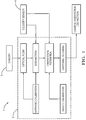
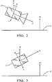
- the used coordinate system is defined in Figs. 2 and 3 , which show side and rear views of the camera 3, respectively.
- the coordinate system is fixed to the camera 3 and has orthogonal coordinates x, y and z.
- Fig. 2 shows the y-z-plane of the coordinate system where a pitch angle ⁇ is defined as the angle between the projection of the normal vector n onto the y-z-plane and the y-axis.
- Fig. 3 shows the x-y-plane of the coordinate system where a roll angle ⁇ is defined as the angle between the projection of the normal vector n onto the x-y-plane and the y-axis.
- a homography matrix H K R ⁇ tn T d K ⁇ 1 and includes the intrinsic camera calibration matrix K , the distance d between the origin of the coordinate system of the camera 3 and the road surface 5, and the relative rotation R and translation t between the two camera positions.
- a priori information is used to solve the estimation problem.
- the vehicle's velocity v is provided via a bus system and the time s between two image captures is given in the data sheet of the camera 3.
- the distance d can be measured and is assumed to be constant.
- the intrinsic camera calibration K is known by a standard calibration procedure.
- the components R and t ', which are called egomotion, of the homography can either be provided by an inertial measurement unit (IMU) or by a vision based motion estimation.
- IMU inertial measurement unit
- vision based approach is employed to determine egomotion, which is discussed in more detail further below.
- the normal vector n is estimated to estimate the pitch angle ⁇ and the roll angle ⁇ .
- optical flow (OF) vectors serve as input data.
- An OF vector linearly connects two points in two different images which represent the same object in the world. Therefore, a first point from the first image and a second point from the second image are selected, wherein the first and second points represent the same object.
- a first OF vector connects the first point and the second point.
- Equation (7) is an inhomogeneous equation system and for this reason we are able to solve it with the help of simple least-squares technique with low computational effort.
- a second estimation step is carried out after the first estimation step.
- n y -1/ ⁇ n ⁇ and do the estimation again with the updated n y , wherein the amount ⁇ n ⁇ of the normal vector n is calculated from the results of the first estimation step.
- this procedure reduces ⁇ n ⁇ to ⁇ 1.0004 which satisfies our accuracy demands.
- We choose this heuristic approach in order to avoid involving the additional constraint ⁇ n ⁇ 1 directly to the optimization problem because this would result in a nonlinear problem.
- the approach of defining the parameter space to [n x , n z ] T enables us to estimate the pitch and roll angle from only a single OF vector.
- a third point is selected from the first image and a fourth point is selected from the second image, wherein the third and fourth points represent the same object.
- a second OF vector connects the third point and the fourth point. The first and second estimation steps can then be carried out as described above by using the first OF vector and the second OF vector.
- the assumption that the road surface is the dominant plane allows us to use a random sample consensus (RANSAC) procedure to determine which OF vectors belong to the road surface and which do not.
- a number N of OF vectors is used for the RANSAC procedure, wherein each of the OF vectors connects a respective point in the first image and a respective point in the second image.
- the first and second estimation steps are carried out as described above and an estimation of the normal vector n is obtained.
- the results obtained from each of the OF vectors are used to verify the quality of the estimation.
- From the vectors p in the first image and the results obtained from the estimation of the normal vector n the vectors q in the second image are calculated.
- the vectors q obtained from the estimation are compared to the vectors q obtained from the second image.
- the inlier/outlier decision of the RANSAC approach is made by thresholding the error between the point warped by the estimated homography and the OF vector end point.
- the final estimate of the normal vector n is done by solving the linear equation system which consists of all RANSAC inliers.
- Parameter e defines which proportion of the OF vectors do not belong to the road surface and s represents the amount of OF vectors which is necessary to calculate n .
- the result N 10 of equation (12) indicates that only very little RANSAC iterations are needed to obtain an estimate of the normal vector's components to obtain the pitch angle ⁇ and the roll angle ⁇ of the camera 3.
- the process noise u k is assumed to reflect a normal distribution (zero mean) with variance of the egomotion angle estimation.
- the observation noise v k is determined by evaluating the homography based pitch and roll estimation variance in the experiments.
- ⁇ 2 test In order to ensure that the Kalman filters are defined properly and in order to obtain thresholds for outlier detection we apply ⁇ 2 test.
- the weighted innovation of the Kalman filter y k T S k ⁇ 1 y k ( y k innovation residual, S k innovation covariance) follows a ⁇ 2 distribution (see Yaakov Bar-Shalom. Kalman filtering techniques for radar tracking: K. V.
- the egomotion estimation is, in particular, employed to obtain the relative rotation R and the translation vector t between the two camera positions.
- Vehicle egomotion estimation using monocular vision is a difficult and important problem in vision based driver assistance system application. This difficulties occur mainly from the motion into baseline (camera translation) direction which makes the underlying minimization problem sensitive to noise. Additionally, the environmental conditions like other moving objects, moving shadows in sunlight, but also rain on the windshield and the moving wiper will induce extra outliers which have to be neglected to obtain reliable results.
- the egomotion serves as input for many other problems, like distance estimation in FCW systems, where the pitching of the car lead to gross errors in the determined solution and homography based ground plane estimation, and thus, as such should not waste too much computation time.
- the approach for robust egomotion estimation presented herein includes M-estimator sample consensus (MSAC), which is based on RANSAC and further includes an M-Estimator. Further, transitional and rotational parts of the egomotion are evaluated separately in an iterative scheme where we use a special constraint and add additional weighting parameters. Here we distinguish explicitly between estimation of the translation and the rotation as rotation influences nearby and distant point, while we have only small amount of translation on the points far away. As constraint we take the normalized discrete epipolar constraint (Sampson distance) and use it in an iterative weighted linear least squares approach. These distances are used to determine the weights for our least squares problem in every iteration step. Further we can find a more efficient formulation for our equations to save additional computation steps.
- MSAC M-estimator sample consensus
- Fig. 4 shows a flow chart illustrating the algorithm used herein.
- the algorthm includes that in each iteration step the normalization terms ⁇ t k and ⁇ ⁇ k are calculated and, subsequently, translation and rotation are updated using the calculated normalization terms ⁇ t k and ⁇ ⁇ k , respectively.
- the translation is normalized to 1 using the euclidean norm
- f denotes the focal length of the camera model
- Z j is the triangulated depth of the appropriate 3D-Point
- v is the vehicle velocity and s the time between two images.
- the depth is updated after every iteration step as well as the weight w d j using the updated translation.
- a discretized weight it is also possible to use a scaled version between 0 and 1.
- the parameters ⁇ 1 , ⁇ 2 have to be chosen carefully to only slightly influence the best model selection.
- the inlier selection itself can also be enhanced by triangulating our feature tracks and apply a positive depth constraint, because all the points visible in the video image should have a positive depth.
Landscapes
- Engineering & Computer Science (AREA)
- Physics & Mathematics (AREA)
- General Physics & Mathematics (AREA)
- Theoretical Computer Science (AREA)
- Computer Vision & Pattern Recognition (AREA)
- Mechanical Engineering (AREA)
- Geometry (AREA)
- Image Analysis (AREA)
Abstract
providing a first image and a subsequent second image captured by the camera;
selecting a first point from the first image and a second point from the second image, wherein the first and second points represent the same object;
defining a first optical flow vector connecting the first point and the second point; carrying out a first estimation step comprising estimating two components of the normal vector in the camera coordinate system by using the first optical flow vector and restricting parameter space to only the two components of the normal vector, wherein a linear equation system derived from a homography matrix that represents a projective transformation between the first image and the second image is provided and the two components of the normal vector in the camera coordinate system are estimated by solving the linear equation system; and determining the orientation of the camera relative to the surface using the results of the first estimation step.
Description
- The invention concerns a method and a device for estimating an orientation of a camera relative to a surface, in particular a road surface.
- Many vision based advanced driver assistance systems (ADAS) algorithms require information about the orientation, in particular pitch and roll angles, of the vehicle-mounted camera to the road surface. For instance, forward collision warning (FCW) systems determine the distance between the ego-vehicle and a preceding vehicle. In order to calculate this distance the orientation of the ego-vehicle to the road surface has to be known. If the camera orientation is not known sufficiently, FCW algorithms generate wrong output signals which can distract the driver or cause a risky steering or braking reaction.
- It is usual practice to determine a static camera orientation, an extrinsic calibration, for stationary vehicles with the help of a calibration pattern. While a car moves, the orientation of the camera to the road surface is no longer static but time-dependent. Braking and acceleration maneuvers as well as road surface irregularities cause fast and notable camera orientation changes. Furthermore, a long-time orientation offset, which differs from the static calibration, can be caused by additional load.
- The orientation of the camera to the road surface can be described by a homography which represents a projective transformation between two different images of the same plane, which is here the road surface, captured from two different camera positions. The extraction of angle information from a homography matrix is possible but not recommended due to parameter ambiguities.
- It is an underlying object of the invention to provide a method that allows to efficiently estimate an orientation of a camera relative to a surface with low computational effort. It is further an object of the invention to provide a device for estimating an orientation of a camera relative to a surface.
- The object underlying the invention is satisfied by the features of the independent claims. Advantageous further developments and aspects of the invention are set forth in the dependent claims.
- In one aspect of the invention a method of estimating an orientation of a camera relative to a surface is provided, wherein a camera coordinate system is defined and a normal vector normal to the surface is represented by three components in the camera coordinate system. According to the method a first image and a subsequent second image captured by the camera are provided and a first point is selected from the first image and a second point is selected from the second image, wherein the first and second points represent the same object. Further, a first optical flow vector connecting the first point and the second point is defined. A first estimation step is carried out that comprises estimating two components of the normal vector in the camera coordinate system by using the first optical flow vector and restricting parameter space to only the two components of the normal vector. A linear equation system derived from a homography matrix that represents a projective transformation between the first image and the second image is provided and the two components of the normal vector in the camera coordinate system are estimated by solving the linear equation system. The orientation of the camera relative to the surface is determined using the results of the first estimation step.
- The restriction of the parameter space to only two components of the normal vector allows a fast estimation of the orientation of the camera. No initial parameter guess is required to estimate the orientation.
- In particular, a distance between the origin of the camera coordinate system and the surface, and the velocity of a vehicle on that the camera is mounted are parameters of the linear equation system.
- In a further embodiment, a second estimation step subsequent to the first estimation step is carried out that comprises estimating the two components of the normal vector in the camera coordinate system again by using the first optical flow vector and setting the component of the normal vector neglected in the first estimation step to a value derived from the first estimation step. The two components of the normal vector in the camera coordinate system are estimated by solving the linear equation system. The orientation of the camera relative to the surface is determined by using the components of the normal vector estimated in the second estimation step.
- In the second estimation step the component of the normal vector neglected in the first estimation step may be set to the inverse of the amount of the normal vector derived from the first estimation step.
- In yet a further embodiment, a second optical flow vector is defined connecting a third point selected from the first image and a fourth point selected from the second image, wherein the third and fourth points represent the same object. The two components of the normal vector in the camera coordinate system are estimated in the first estimation step by using the first optical flow vector and the second optical flow vector. In particular, the two components of the normal vector in the camera coordinate system are estimated in the second estimation step by using the first optical flow vector and the second optical flow vector.
- The method may comprise using a linear least squares estimation in the first estimation step and/or the second estimation step in order to estimate the two components of the normal vector in the camera coordinate system.
- In one embodiment, a plurality of optical flow vectors each connecting a respective point in the first image and a respective point in the second image is defined, wherein both respective points represent the same object. The two components of the normal vector in the camera coordinate system are estimated for each of the plurality of optical flow vectors by carrying out the first estimation step and/or the second estimation step. The optical flow vector that produces the highest number of inliers is determined.
- In addition, the two components of the normal vector may be estimated in the camera coordinate system by carrying out the first estimation step and/or the second estimation step for all inliers.
- The determination of the orientation of the camera relative to the surface may comprise determining a pitch angle and a role angle of the camera relative to the surface.
- The pitch angle and the role angle may be filtered, in particular by a Kalman filter.
- The rotation and translation of the camera between capturing the first image and capturing the second image may be provided by a vision based egomotion estimation using an MSAC (M-estimator sample consensus) algorithm.
- Translational and rotational parts of the egomotion may be estimated separately in an iterative scheme.
- An iterative weighted linear least squares approach may be used with a normalized discrete epipolar constraint.
- According to a further embodiment a plurality of inliers are obtained as a result of the MSAC algorithm and for each of the inliers the corresponding optical flow vector length is calculated using the rotation and translation of the camera between capturing the first image and capturing the second image provided by the MSAC algorithm. Each of the inliers is weighted according to the corresponding optical flow vector length, and the translation of the camera between capturing the first image and capturing the second image is estimated again using the weighted inliers.
- The camera may be mounted on a vehicle and the surface may be a road surface. In particular, the vehicle comprises a system with an ADAS algorithm, in particular a camera based ADAS system, for example a FCW, lane departure warning (LDP) or pedestrian detection (PED) system.
- According to a further aspect of the invention a device for estimating an orientation of a camera relative to a surface is provided, wherein a camera coordinate system is defined and a normal vector normal to the surface is represented by three components in the camera coordinate system. The device is configured to receive a first image and a subsequent second image captured by the camera, select a first point from the first image and a second point from the second image, wherein the first and second points represent the same object, define a first optical flow vector connecting the first point and the second point, carry out a first estimation step comprising estimating two components of the normal vector in the camera coordinate system by using the first optical flow vector and restricting parameter space to only the two components of the normal vector, wherein the two components of the normal vector in the camera coordinate system are estimated by solving a linear equation system derived from a homography matrix that represents a projective transformation between the first image and the second image, and determine the orientation of the camera relative to the surface using the results of the first estimation step.
- The device may comprise the embodiments disclosed above in connection with the method of estimating an orientation of a camera relative to a surface.
- The invention will be described in more detail in the following in an exemplary manner with reference to an embodiment and to the drawings. There are shown in these:
- Fig. 1
- a schematic representation of a system and a device for estimating an orientation of a camera relative to a road surface;
- Fig. 2
- a schematic representation of a camera side view illustrating the geometry of the pitch angle θ;
- Fig. 3
- a schematic representation of a camera rear view illustrating the geometry of the roll angle Φ; and
- Fig. 4
- a flow chart illustrating vehicle egomotion estimation.
- A
system 1 for estimating an orientation of a camera relative to a road surface is schematically illustrated inFig. 1 . Thesystem 1 includes adevice 2, acamera 3 and avelocity sensor 4. In the instant embodiment, thecamera 3 is mounted on a vehicle and captures images, for example, of the area in front of the vehicle. Thevelocity sensor 4 measures the velocity of the vehicle. Thecamera 3 and thevelocity sensor 4 provide thedevice 2 with the captured images and the measured velocity data, respectively. Thedevice 2 uses the captured images and the measured velocity data in order to estimate and output data regarding orientation and motion of thecamera 3. For that purpose, thedevice 2 may include a processor and employs the algorithms explained in the following. - The homography between two images of the
road surface 5 captured from successive poses of the moving vehicle includes information about the camera's roll and pitch angle relative to theroad surface 5. The used coordinate system is defined inFigs. 2 and 3 , which show side and rear views of thecamera 3, respectively. The coordinate system is fixed to thecamera 3 and has orthogonal coordinates x, y and z. The normal vector of theroad surface 5 is n = [nx , ny , nz ] T.Fig. 2 shows the y-z-plane of the coordinate system where a pitch angle θ is defined as the angle between the projection of the normal vector n onto the y-z-plane and the y-axis.Fig. 3 shows the x-y-plane of the coordinate system where a roll angle Φ is defined as the angle between the projection of the normal vector n onto the x-y-plane and the y-axis. - The pitch angle θ and the roll angle Φ between the
camera 3 and theroad surface 5 are also defined by equations (1) and (2):

- Information about the pitch angle θ and the roll angle Φ is included in a homography which represents a projective transformation between two different images of the
road surface 5 captured subsequently from two different positions of thecamera 3. A homography matrix H is defined as follows
camera 3 and theroad surface 5, and the relative rotation R and translation t between the two camera positions. The metric translation t is calculated by t = t'vs consisting of a normalized translation vector t', the vehicle velocity v measured by thevelocity sensor 4 and the time s elapsed between the two image captures. - A priori information is used to solve the estimation problem. The vehicle's velocity v is provided via a bus system and the time s between two image captures is given in the data sheet of the
camera 3. The distance d can be measured and is assumed to be constant. The intrinsic camera calibration K is known by a standard calibration procedure. The components R and t ', which are called egomotion, of the homography can either be provided by an inertial measurement unit (IMU) or by a vision based motion estimation. Here a vision based approach is employed to determine egomotion, which is discussed in more detail further below. - The normal vector n is estimated to estimate the pitch angle θ and the roll angle Φ. The normal vector n in the homography is conditioned by ∥ n ∥ = 1. With that knowledge the estimation problem is reduced from three parameters (nx, ny nz ) to two parameters, namely nx and nz , to obtain the pitch angle θ and the roll angle Φ.
- The
camera 3 captures a first image and, subsequently after the time s, thecamera 3 captures a second image. For the angle estimation algorithm optical flow (OF) vectors serve as input data. An OF vector linearly connects two points in two different images which represent the same object in the world. Therefore, a first point from the first image and a second point from the second image are selected, wherein the first and second points represent the same object. A first OF vector connects the first point and the second point. - The positions of the points in the images connected by OF vectors are represented by homogenous vectors p = [p 1, p 2, p 3] T for the first image and q = [q 1, q 2, q 3] T for the second image. The homography matrix H transforms the homogenous vector p to the homogenous vector

- In order to calculate the image coordinates (u, v) we can write


- To obtain the desired normal components nx and nz we insert equation (4) into equations (5) and (6). Each component of the homography matrix H as given in equation (3) is then dissembled into its parts containing the single components of R, t , n , d and K. In order to achieve a simple formula representation following sections use the scaled translation t̃ = t /d and normalized coordinates. After rearranging the equations we obtain the linear equation system


- Variables c 1, c 2 consist of the remaining parts of the rearranged equations


- In a first estimation step, the second component ny of the normal vector n is initially assumed to be -1 (pitch angle θ = 0°, roll angle Φ = 0°) for the estimation. After solving the least-squares problem (equation (7)) the result violates the condition ∥ n ∥ = 1, if the pitch angle θ and the roll angle Φ differ from 0°. In order to deal with this issue, a second estimation step is carried out after the first estimation step.
- In the second estimation step, we calculate ny = -1/∥ n ∥ and do the estimation again with the updated ny , wherein the amount ∥ n ∥ of the normal vector n is calculated from the results of the first estimation step. In general, this procedure reduces ∥ n ∥ to < 1.0004 which satisfies our accuracy demands. We choose this heuristic approach in order to avoid involving the additional constraint ∥ n ∥ = 1 directly to the optimization problem because this would result in a nonlinear problem.
- In theory, the approach of defining the parameter space to [nx , nz ] T enables us to estimate the pitch and roll angle from only a single OF vector. Instead of using one OF vector we can use two OF vectors to achieve a better conditioned problem. In this case, a third point is selected from the first image and a fourth point is selected from the second image, wherein the third and fourth points represent the same object. A second OF vector connects the third point and the fourth point. The first and second estimation steps can then be carried out as described above by using the first OF vector and the second OF vector.
- The assumption that the road surface is the dominant plane allows us to use a random sample consensus (RANSAC) procedure to determine which OF vectors belong to the road surface and which do not. A number N of OF vectors is used for the RANSAC procedure, wherein each of the OF vectors connects a respective point in the first image and a respective point in the second image. For each of the OF vectors the first and second estimation steps are carried out as described above and an estimation of the normal vector n is obtained. In addition, the results obtained from each of the OF vectors are used to verify the quality of the estimation. From the vectors p in the first image and the results obtained from the estimation of the normal vector n the vectors q in the second image are calculated. The vectors q obtained from the estimation are compared to the vectors q obtained from the second image.
- The inlier/outlier decision of the RANSAC approach is made by thresholding the error between the point warped by the estimated homography and the OF vector end point. The higher the number of inliers for an OF vector, the higher is the quality of the estimation based on this OF vector.
- The final estimate of the normal vector n is done by solving the linear equation system which consists of all RANSAC inliers. An estimate how many RANSAC iterations N are needed can be done by

camera 3. - From the OF based estimation approach we finally obtain the normal vector components as well as the pitch angle θ and the roll angle Φ of the
camera 3 relative to theroad surface 5. Additional information is provided by the relative pitch Δθ and the relative roll angle ΔΦ between the first and the second image which can be obtained from the egomotion rotation matrix R. There two information sources are combined into a Kalman filter. Two separate Kalman filters with the same structure are used to estimate the final pitch and roll angle of thecamera 3 for every time step. The system model


- In the following vehicle egomotion estimation is described. The egomotion estimation is, in particular, employed to obtain the relative rotation R and the translation vector t between the two camera positions.
- Vehicle egomotion estimation using monocular vision is a difficult and important problem in vision based driver assistance system application. This difficulties occur mainly from the motion into baseline (camera translation) direction which makes the underlying minimization problem sensitive to noise. Additionally, the environmental conditions like other moving objects, moving shadows in sunlight, but also rain on the windshield and the moving wiper will induce extra outliers which have to be neglected to obtain reliable results. Once the egomotion is computed it serves as input for many other problems, like distance estimation in FCW systems, where the pitching of the car lead to gross errors in the determined solution and homography based ground plane estimation, and thus, as such should not waste too much computation time.
- The approach for robust egomotion estimation presented herein includes M-estimator sample consensus (MSAC), which is based on RANSAC and further includes an M-Estimator. Further, transitional and rotational parts of the egomotion are evaluated separately in an iterative scheme where we use a special constraint and add additional weighting parameters. Here we distinguish explicitly between estimation of the translation and the rotation as rotation influences nearby and distant point, while we have only small amount of translation on the points far away. As constraint we take the normalized discrete epipolar constraint (Sampson distance) and use it in an iterative weighted linear least squares approach. These distances are used to determine the weights for our least squares problem in every iteration step. Further we can find a more efficient formulation for our equations to save additional computation steps. In order to handle outliers we add robust estimation methods like MSAC and M-estimator which allow us to segment the image into foreground (other moving objects or optical flow outliers) and background motion (egomotion) and enhance this with the use of prior information based on the horizontal motion of a vehicle. The algorithm was also successfully tested online and thus is suitable for real time application as it converges really fast.
Fig. 4 shows a flow chart illustrating the algorithm used herein. - Starting from a pyramidal implementation of the KLT feature tracker (see Bouguet, Jean-Yves. Pyramidal implementation of the affine lucas kanade feature tracker description of the algorithm. Intel Corporation, 5:1-10, 2001) for optical flow we derive M feature tracks from the current image i captured by the
camera 3 to the next consecutive image
camera 3 from image to image. The next steps are derived from the epipolar constraint


- Hence we want to find the least squares solution


- Document "Bai, E and Liu, Yun. On the least squares solutions of a system of bilinear equations" (IEEE CONFERENCE ON DECISION AND CONTROL, ) mentions a linear iterative scheme to solve bilinear least squares problems and also establish fast convergence for this algorithm. In document "Narendra, Kumpati S and Gallman, Philip G. An iterative method for the identification of nonlinear systems using a Hammerstein model" (Automatic Control, IEEE Transactions on, 11(3):546-550, 1966) convergence was further proven for the normalized case. We will adopt the idea of this iterative scheme for our purpose and solve two linear least squares problems iteratively, but with the addition that our right side of the equation is also dependent of the estimation parameters. First we rewrite the equation (18) in terms of t and Ω:


- We now proceed the following way using weighted linear least squares for every equation. Therefore the normalization term µ j is used as weighting and linearized twice in every iteration and the least squares functions are defined as follows:


- Then the algorithm can be described
Algorithm 1 Solving Ω, t iterativelyRequire: Optical Flow computed from the former to the current frame and converted to canonical undistorted coordinates ( xj , x' j ), initial Ω0, t 0 1: function COMPUTEEGOMOTION(Ω, t , xj , x' j ) 2: 3: Ω ← Ω0 4: t ← t 0 5: X̂j ← x j × x'j 6: repeat 7: 8: 
9: 
10: 
11: 
12: until converge - As shown above, the algorthm includes that in each iteration step the normalization terms


- In order to save computational cost we can formulate equations (20) and (21) in a more efficient way using xj = [(xj )1 (xj )2 1] T and x'j = [(x'j )1 (x'j )2 1] T , if we define:


- Then equation (20) can be shortened to:

- For the rotational part we define:


- The rotational equation (21) then becomes:

- If we are not using simulated data for optical flow hypothesis generation, the problem of outlier occurs in real world scenarios as the solution of the optical flow problem itself is difficult. The quality of the egomotion estimation suffers from that and therefore robust estimation is needed. One approach is to use RANSAC (see Fischler, Martin A and Bolles, Robert C. Random sample consensus: a paradigm for model fitting with applications to image analysis and automated cartography. Communications of the ACM, 24(6):381-395, 1981), where the model is first computed from random selected minimal sets of optical flow samples and after that the solution is selected which minimizes the
cost function 

- In documents "Torr, Phil and Zisserman, Andrew. Robust computation and parametrization of multiple view relations" (Computer Vision, 1998. Sixth International Conference on, pages 727-732, 1998. IEEE) and "Torr, Philip HS and Zisserman, Andrew. MLESAC: A new robust estimator with application to estimating image geometry" (Computer Vision and Image Understanding, 78(1):138-156, 2000) a further concept was presented called MSAC (M-estimator sample consensus). The cost function ρ(·) changes to

- The difference now is that inliers also get a penalty depending on their data fitting. The constant threshold for the outlier remains constant but now is given through the exact threshold bound. Because MSAC has proven to be more robust opposite to RANSAC in motion estimation application, we decided to use MSAC for our approach. After the MSAC routine further estimation is performed on all inliers in the image provided by the minimal solution from the sample set from the MSAC step. Further we will integrate a M-estimator to further improve our results. Here we tested the Huber k-estimator wH (·)

- As distant points only have a small amount of translation, we want to prefer those features which have an appropriate optical flow vector length for the translation estimation after the MSAC loop. We therefore multiply a weight called


- Often we have prior knowledge about the parameters which we will also want to consider, e.g., approximately forward motion into FOE-direction or both epipoles should be near a fixed horizon line hy , which is calibrated before. But we also do not want to rely too strictly on this assumption. We include this additional information using a Tikhonov-like model in the MSAC-step, instead of directly discard estimated model parameters for a sample set, which do not fit to the prior information. If we denote the y-coordinate of the left epipole with


- The inlier selection itself can also be enhanced by triangulating our feature tracks and apply a positive depth constraint, because all the points visible in the video image should have a positive depth.
- List of reference signs
- 1
- system
- 2
- device
- 3
- camera
- 4
- velocity sensor
- 5
- road surface
Claims (15)
- A method of estimating an orientation of a camera (3) relative to a surface (5), wherein a camera coordinate system is defined and a normal vector normal to the surface (5) is represented by three components in the camera coordinate system, the method comprising:providing a first image and a subsequent second image captured by the camera (3);selecting a first point from the first image and a second point from the second image, wherein the first and second points represent the same object;defining a first optical flow vector connecting the first point and the second point;carrying out a first estimation step comprising estimating two components of the normal vector in the camera coordinate system by using the first optical flow vector and restricting parameter space to only the two components of the normal vector, wherein a linear equation system derived from a homography matrix that represents a projective transformation between the first image and the second image is provided and the two components of the normal vector in the camera coordinate system are estimated by solving the linear equation system; anddetermining the orientation of the camera (3) relative to the surface (5) using the results of the first estimation step.
- The method as claimed in claim 1, comprising carrying out a second estimation step subsequent to the first estimation step that comprises estimating the two components of the normal vector in the camera coordinate system again by using the first optical flow vector and setting the component of the normal vector neglected in the first estimation step to a value derived from the first estimation step, wherein the two components of the normal vector in the camera coordinate system are estimated by solving the linear equation system and the orientation of the camera (3) relative to the surface (5) is determined by using the components of the normal vector estimated in the second estimation step.
- The method as claimed in claim 2, wherein in the second estimation step the component of the normal vector neglected in the first estimation step is set to the inverse of the amount of the normal vector derived from the first estimation step.
- The method as claimed in one of the preceding claims, comprising selecting a third point from the first image and a fourth point from the second image, wherein the third and fourth points represent the same object;
defining a second optical flow vector connecting the third point and the fourth point;
estimating the two components of the normal vector in the camera coordinate system in the first estimation step by using the first optical flow vector and the second optical flow vector; and
in particular, estimating the two components of the normal vector in the camera coordinate system in the second estimation step by using the first optical flow vector and the second optical flow vector. - The method as claimed in one of the preceding claims, comprising using a linear least squares estimation in the first estimation step and/or the second estimation step in order to estimate the two components of the normal vector in the camera coordinate system.
- The method as claimed in one of the preceding claims, comprising defining a plurality of optical flow vectors each connecting a respective point in the first image and a respective point in the second image, wherein both respective points represent the same object;
estimating the two components of the normal vector in the camera coordinate system for each of the plurality of optical flow vectors by carrying out the first estimation step and/or the second estimation step; and determining the one of the optical flow vectors that produces the highest number of inliers. - The method as claimed in claim 6, comprising estimating the two components of the normal vector in the camera coordinate system by carrying out the first estimation step and/or the second estimation step for all inliers.
- The method as claimed in one of the preceding claims, wherein determining the orientation of the camera (3) relative to the surface (5) comprises determining a pitch angle and a role angle of the camera (3) relative to the surface (5).
- The method as claimed in claim 8, comprising filtering, in particular Kalman filtering, the pitch angle and the role angle.
- The method as claimed in one of the preceding claims, wherein a rotation and a translation of the camera (3) between capturing the first image and capturing the second image are provided by a vision based egomotion estimation using an MSAC (M-estimator sample consensus) algorithm.
- The method as claimed in claim 10, wherein a translational part and a rotational part of the egomotion are estimated separately in an iterative scheme.
- The method as claimed in one of the claims 10 and 11, wherein an iterative weighted linear least squares approach is used with a normalized discrete epipolar constraint.
- The method as claimed in one of the claims 10 to 12, wherein a plurality of inliers are obtained as a result of the MSAC algorithm and for each of the inliers the corresponding optical flow vector length is calculated using the rotation and translation of the camera (3) between capturing the first image and capturing the second image provided by the MSAC algorithm, wherein each of the inliers is weighted according to the corresponding optical flow vector length and the translation of the camera (3) between capturing the first image and capturing the second image is estimated again using the weighted inliers.
- The method as claimed in one of the preceding claims, wherein the camera (3) is mounted on a vehicle and the surface is a road surface (5).
- A device (2) for estimating an orientation of a camera (3) relative to a surface (5), wherein a camera coordinate system is defined and a normal vector normal to the surface (5) is represented by three components in the camera coordinate system, the device (2) is configured to receive a first image and a subsequent second image captured by the camera (3),
select a first point from the first image and a second point from the second image, wherein the first and second points represent the same object, define a first optical flow vector connecting the first point and the second point,
carry out a first estimation step comprising estimating two components of the normal vector in the camera coordinate system by using the first optical flow vector and restricting parameter space to only the two components of the normal vector, wherein the two components of the normal vector in the camera coordinate system are estimated by solving a linear equation system derived from a homography matrix that represents a projective transformation between the first image and the second image, and determine the orientation of the camera (3) relative to the surface (5) using the results of the first estimation step.
Priority Applications (3)
| Application Number | Priority Date | Filing Date | Title |
|---|---|---|---|
| EP16151517.6A EP3193306B8 (en) | 2016-01-15 | 2016-01-15 | A method and a device for estimating an orientation of a camera relative to a road surface |
| US15/384,615 US10102644B2 (en) | 2016-01-15 | 2016-12-20 | Method and a device for estimating an orientation of a camera relative to a road surface |
| CN201710070098.1A CN106981074B (en) | 2016-01-15 | 2017-01-10 | Method and apparatus for estimating an orientation of a camera relative to a surface |
Applications Claiming Priority (1)
| Application Number | Priority Date | Filing Date | Title |
|---|---|---|---|
| EP16151517.6A EP3193306B8 (en) | 2016-01-15 | 2016-01-15 | A method and a device for estimating an orientation of a camera relative to a road surface |
Publications (3)
| Publication Number | Publication Date |
|---|---|
| EP3193306A1 true EP3193306A1 (en) | 2017-07-19 |
| EP3193306B1 EP3193306B1 (en) | 2018-11-28 |
| EP3193306B8 EP3193306B8 (en) | 2019-01-23 |
Family
ID=55221284
Family Applications (1)
| Application Number | Title | Priority Date | Filing Date |
|---|---|---|---|
| EP16151517.6A Active EP3193306B8 (en) | 2016-01-15 | 2016-01-15 | A method and a device for estimating an orientation of a camera relative to a road surface |
Country Status (3)
| Country | Link |
|---|---|
| US (1) | US10102644B2 (en) |
| EP (1) | EP3193306B8 (en) |
| CN (1) | CN106981074B (en) |
Cited By (2)
| Publication number | Priority date | Publication date | Assignee | Title |
|---|---|---|---|---|
| CN111429530A (en) * | 2020-04-10 | 2020-07-17 | 浙江大华技术股份有限公司 | Coordinate calibration method and related device |
| US11557089B1 (en) | 2022-03-25 | 2023-01-17 | Valerann Ltd | System and method for determining a viewpoint of a traffic camera |
Families Citing this family (13)
| Publication number | Priority date | Publication date | Assignee | Title |
|---|---|---|---|---|
| US10156441B2 (en) * | 2016-01-05 | 2018-12-18 | Texas Instruments Incorporated | Ground plane estimation in a computer vision system |
| US10911745B2 (en) * | 2016-12-28 | 2021-02-02 | Texas Instruments Incorporated | Calibration of a surround view camera system |
| CN107388967B (en) * | 2017-08-14 | 2019-11-12 | 上海汽车集团股份有限公司 | A kind of outer parameter compensation method of vehicle-mounted three-dimensional laser sensor and device |
| CN108171784B (en) * | 2017-12-22 | 2021-06-01 | 福建省天奕网络科技有限公司 | Rendering method and terminal |
| CN108154552A (en) * | 2017-12-26 | 2018-06-12 | 中国科学院深圳先进技术研究院 | A kind of stereo laparoscope method for reconstructing three-dimensional model and device |
| GB201804082D0 (en) * | 2018-03-14 | 2018-04-25 | Five Ai Ltd | Image annotation |
| CN110567469B (en) | 2018-06-05 | 2021-07-20 | 北京市商汤科技开发有限公司 | Visual positioning method and device, electronic equipment and system |
| KR102559203B1 (en) * | 2018-10-01 | 2023-07-25 | 삼성전자주식회사 | Method and apparatus of outputting pose information |
| EP3667362A1 (en) * | 2018-12-10 | 2020-06-17 | Infineon Technologies AG | Methods and apparatuses for determining rotation parameters for conversion between coordinate systems |
| CN111325800A (en) * | 2018-12-17 | 2020-06-23 | 北京华航无线电测量研究所 | Monocular vision system pitch angle calibration method |
| DE102020101718A1 (en) | 2020-01-24 | 2021-07-29 | Car.Software Estonia As | Method and device for determining the orientation of a surface of an object |
| CN112284380A (en) * | 2020-09-23 | 2021-01-29 | 深圳市富临通实业股份有限公司 | Nonlinear estimation method and system based on fusion of optical flow and IMU (inertial measurement Unit) |
| DE102021205852A1 (en) | 2021-06-10 | 2022-12-15 | Robert Bosch Gesellschaft mit beschränkter Haftung | Method and device for providing contour data with regard to a surface contour of a road surface on which a vehicle is driving, and method and device for controlling an operation of a vehicle |
Citations (5)
| Publication number | Priority date | Publication date | Assignee | Title |
|---|---|---|---|---|
| US6535114B1 (en) * | 2000-03-22 | 2003-03-18 | Toyota Jidosha Kabushiki Kaisha | Method and apparatus for environment recognition |
| US20100157058A1 (en) * | 2008-11-20 | 2010-06-24 | Hella Kgaa Hueck & Co. | Method and Device for Compensating a Roll Angle |
| US20130044186A1 (en) * | 2011-08-19 | 2013-02-21 | Hailin Jin | Plane-based Self-Calibration for Structure from Motion |
| EP2736013A2 (en) * | 2012-11-21 | 2014-05-28 | Fujitsu Limited | Calibration of multiple cameras on a moving object |
| EP2840550A1 (en) * | 2013-08-19 | 2015-02-25 | Delphi Technologies, Inc. | Camera pose estimation |
Family Cites Families (2)
| Publication number | Priority date | Publication date | Assignee | Title |
|---|---|---|---|---|
| EP2618305B1 (en) * | 2012-01-20 | 2014-04-30 | ESG Elektroniksystem- und Logistik-GmbH | Method and device for online calibration of vehicle cameras |
| CN102999759B (en) * | 2012-11-07 | 2015-10-07 | 东南大学 | A kind of state of motion of vehicle method of estimation based on light stream |
-
2016
- 2016-01-15 EP EP16151517.6A patent/EP3193306B8/en active Active
- 2016-12-20 US US15/384,615 patent/US10102644B2/en active Active
-
2017
- 2017-01-10 CN CN201710070098.1A patent/CN106981074B/en active Active
Patent Citations (5)
| Publication number | Priority date | Publication date | Assignee | Title |
|---|---|---|---|---|
| US6535114B1 (en) * | 2000-03-22 | 2003-03-18 | Toyota Jidosha Kabushiki Kaisha | Method and apparatus for environment recognition |
| US20100157058A1 (en) * | 2008-11-20 | 2010-06-24 | Hella Kgaa Hueck & Co. | Method and Device for Compensating a Roll Angle |
| US20130044186A1 (en) * | 2011-08-19 | 2013-02-21 | Hailin Jin | Plane-based Self-Calibration for Structure from Motion |
| EP2736013A2 (en) * | 2012-11-21 | 2014-05-28 | Fujitsu Limited | Calibration of multiple cameras on a moving object |
| EP2840550A1 (en) * | 2013-08-19 | 2015-02-25 | Delphi Technologies, Inc. | Camera pose estimation |
Non-Patent Citations (10)
Cited By (3)
| Publication number | Priority date | Publication date | Assignee | Title |
|---|---|---|---|---|
| CN111429530A (en) * | 2020-04-10 | 2020-07-17 | 浙江大华技术股份有限公司 | Coordinate calibration method and related device |
| CN111429530B (en) * | 2020-04-10 | 2023-06-02 | 浙江大华技术股份有限公司 | Coordinate calibration method and related device |
| US11557089B1 (en) | 2022-03-25 | 2023-01-17 | Valerann Ltd | System and method for determining a viewpoint of a traffic camera |
Also Published As
| Publication number | Publication date |
|---|---|
| CN106981074A (en) | 2017-07-25 |
| US10102644B2 (en) | 2018-10-16 |
| EP3193306B8 (en) | 2019-01-23 |
| EP3193306B1 (en) | 2018-11-28 |
| CN106981074B (en) | 2021-05-25 |
| US20170206674A1 (en) | 2017-07-20 |
Similar Documents
| Publication | Publication Date | Title |
|---|---|---|
| EP3193306B1 (en) | A method and a device for estimating an orientation of a camera relative to a road surface | |
| US10097812B2 (en) | Stereo auto-calibration from structure-from-motion | |
| US9576207B2 (en) | Method for angle calibration of the position of a video camera on board an automotive vehicle | |
| JP5689907B2 (en) | Method for improving the detection of a moving object in a vehicle | |
| US10424081B2 (en) | Method and apparatus for calibrating a camera system of a motor vehicle | |
| US11407363B2 (en) | Method for calculating a tow hitch position | |
| JP4480083B2 (en) | Object recognition device | |
| US8831290B2 (en) | Method and system for determining poses of vehicle-mounted cameras for in-road obstacle detection | |
| US10008002B2 (en) | Single-camera distance estimation | |
| US8885049B2 (en) | Method and device for determining calibration parameters of a camera | |
| EP2757527B1 (en) | System and method for distorted camera image correction | |
| Chien et al. | Visual odometry driven online calibration for monocular lidar-camera systems | |
| EP2901236B1 (en) | Video-assisted target location | |
| KR20150032789A (en) | Method for estimating ego motion of an object | |
| US10832428B2 (en) | Method and apparatus for estimating a range of a moving object | |
| US8675047B2 (en) | Detection device of planar area and stereo camera system | |
| WO2016146559A1 (en) | Method for determining a position of an object in a three-dimensional world coordinate system, computer program product, camera system and motor vehicle | |
| JP2009086882A (en) | Object detector | |
| Zhao et al. | An automatic online camera calibration system for vehicular applications | |
| Westerhoff et al. | Development and comparison of homography based estimation techniques for camera to road surface orientation | |
| Cheda et al. | Camera egomotion estimation in the ADAS context | |
| JP2005148784A (en) | Detector for traveling lane on road surface | |
| Pagel | Robust monocular egomotion estimation based on an iekf | |
| Weydert | Model-based ego-motion and vehicle parameter estimation using visual odometry | |
| Leßmann et al. | Improving robustness for real-time vehicle egomotion estimation |
Legal Events
| Date | Code | Title | Description |
|---|---|---|---|
| PUAI | Public reference made under article 153(3) epc to a published international application that has entered the european phase |
Free format text: ORIGINAL CODE: 0009012 |
|
| STAA | Information on the status of an ep patent application or granted ep patent |
Free format text: STATUS: THE APPLICATION HAS BEEN PUBLISHED |
|
| AK | Designated contracting states |
Kind code of ref document: A1 Designated state(s): AL AT BE BG CH CY CZ DE DK EE ES FI FR GB GR HR HU IE IS IT LI LT LU LV MC MK MT NL NO PL PT RO RS SE SI SK SM TR |
|
| AX | Request for extension of the european patent |
Extension state: BA ME |
|
| STAA | Information on the status of an ep patent application or granted ep patent |
Free format text: STATUS: REQUEST FOR EXAMINATION WAS MADE |
|
| 17P | Request for examination filed |
Effective date: 20180119 |
|
| GRAP | Despatch of communication of intention to grant a patent |
Free format text: ORIGINAL CODE: EPIDOSNIGR1 |
|
| RBV | Designated contracting states (corrected) |
Designated state(s): AL AT BE BG CH CY CZ DE DK EE ES FI FR GB GR HR HU IE IS IT LI LT LU LV MC MK MT NL NO PL PT RO RS SE SI SK SM TR |
|
| STAA | Information on the status of an ep patent application or granted ep patent |
Free format text: STATUS: GRANT OF PATENT IS INTENDED |
|
| RIC1 | Information provided on ipc code assigned before grant |
Ipc: G06T 7/60 20170101ALI20180215BHEP Ipc: G06T 3/20 20060101ALI20180215BHEP Ipc: G06T 7/00 20170101AFI20180215BHEP Ipc: G06T 7/70 20170101ALI20180215BHEP |
|
| INTG | Intention to grant announced |
Effective date: 20180301 |
|
| GRAS | Grant fee paid |
Free format text: ORIGINAL CODE: EPIDOSNIGR3 |
|
| GRAA | (expected) grant |
Free format text: ORIGINAL CODE: 0009210 |
|
| STAA | Information on the status of an ep patent application or granted ep patent |
Free format text: STATUS: THE PATENT HAS BEEN GRANTED |
|
| AK | Designated contracting states |
Kind code of ref document: B1 Designated state(s): AL AT BE BG CH CY CZ DE DK EE ES FI FR GB GR HR HU IE IS IT LI LT LU LV MC MK MT NL NO PL PT RO RS SE SI SK SM TR |
|
| REG | Reference to a national code |
Ref country code: CH Ref legal event code: EP |
|
| REG | Reference to a national code |
Ref country code: AT Ref legal event code: REF Ref document number: 1071113 Country of ref document: AT Kind code of ref document: T Effective date: 20181215 |
|
| RAP2 | Party data changed (patent owner data changed or rights of a patent transferred) |
Owner name: APTIV TECHNOLOGIES LIMITED |
|
| REG | Reference to a national code |
Ref country code: DE Ref legal event code: R096 Ref document number: 602016007466 Country of ref document: DE |
|
| REG | Reference to a national code |
Ref country code: IE Ref legal event code: FG4D |
|
| REG | Reference to a national code |
Ref country code: CH Ref legal event code: PK Free format text: BERICHTIGUNG B8 |
|
| REG | Reference to a national code |
Ref country code: NL Ref legal event code: MP Effective date: 20181128 |
|
| REG | Reference to a national code |
Ref country code: LT Ref legal event code: MG4D |
|
| REG | Reference to a national code |
Ref country code: AT Ref legal event code: MK05 Ref document number: 1071113 Country of ref document: AT Kind code of ref document: T Effective date: 20181128 |
|
| PG25 | Lapsed in a contracting state [announced via postgrant information from national office to epo] |
Ref country code: LT Free format text: LAPSE BECAUSE OF FAILURE TO SUBMIT A TRANSLATION OF THE DESCRIPTION OR TO PAY THE FEE WITHIN THE PRESCRIBED TIME-LIMIT Effective date: 20181128 Ref country code: ES Free format text: LAPSE BECAUSE OF FAILURE TO SUBMIT A TRANSLATION OF THE DESCRIPTION OR TO PAY THE FEE WITHIN THE PRESCRIBED TIME-LIMIT Effective date: 20181128 Ref country code: NO Free format text: LAPSE BECAUSE OF FAILURE TO SUBMIT A TRANSLATION OF THE DESCRIPTION OR TO PAY THE FEE WITHIN THE PRESCRIBED TIME-LIMIT Effective date: 20190228 Ref country code: BG Free format text: LAPSE BECAUSE OF FAILURE TO SUBMIT A TRANSLATION OF THE DESCRIPTION OR TO PAY THE FEE WITHIN THE PRESCRIBED TIME-LIMIT Effective date: 20190228 Ref country code: IS Free format text: LAPSE BECAUSE OF FAILURE TO SUBMIT A TRANSLATION OF THE DESCRIPTION OR TO PAY THE FEE WITHIN THE PRESCRIBED TIME-LIMIT Effective date: 20190328 Ref country code: HR Free format text: LAPSE BECAUSE OF FAILURE TO SUBMIT A TRANSLATION OF THE DESCRIPTION OR TO PAY THE FEE WITHIN THE PRESCRIBED TIME-LIMIT Effective date: 20181128 Ref country code: AT Free format text: LAPSE BECAUSE OF FAILURE TO SUBMIT A TRANSLATION OF THE DESCRIPTION OR TO PAY THE FEE WITHIN THE PRESCRIBED TIME-LIMIT Effective date: 20181128 Ref country code: LV Free format text: LAPSE BECAUSE OF FAILURE TO SUBMIT A TRANSLATION OF THE DESCRIPTION OR TO PAY THE FEE WITHIN THE PRESCRIBED TIME-LIMIT Effective date: 20181128 Ref country code: FI Free format text: LAPSE BECAUSE OF FAILURE TO SUBMIT A TRANSLATION OF THE DESCRIPTION OR TO PAY THE FEE WITHIN THE PRESCRIBED TIME-LIMIT Effective date: 20181128 |
|
| PG25 | Lapsed in a contracting state [announced via postgrant information from national office to epo] |
Ref country code: SE Free format text: LAPSE BECAUSE OF FAILURE TO SUBMIT A TRANSLATION OF THE DESCRIPTION OR TO PAY THE FEE WITHIN THE PRESCRIBED TIME-LIMIT Effective date: 20181128 Ref country code: AL Free format text: LAPSE BECAUSE OF FAILURE TO SUBMIT A TRANSLATION OF THE DESCRIPTION OR TO PAY THE FEE WITHIN THE PRESCRIBED TIME-LIMIT Effective date: 20181128 Ref country code: RS Free format text: LAPSE BECAUSE OF FAILURE TO SUBMIT A TRANSLATION OF THE DESCRIPTION OR TO PAY THE FEE WITHIN THE PRESCRIBED TIME-LIMIT Effective date: 20181128 Ref country code: GR Free format text: LAPSE BECAUSE OF FAILURE TO SUBMIT A TRANSLATION OF THE DESCRIPTION OR TO PAY THE FEE WITHIN THE PRESCRIBED TIME-LIMIT Effective date: 20190301 Ref country code: PT Free format text: LAPSE BECAUSE OF FAILURE TO SUBMIT A TRANSLATION OF THE DESCRIPTION OR TO PAY THE FEE WITHIN THE PRESCRIBED TIME-LIMIT Effective date: 20190328 |
|
| PG25 | Lapsed in a contracting state [announced via postgrant information from national office to epo] |
Ref country code: NL Free format text: LAPSE BECAUSE OF FAILURE TO SUBMIT A TRANSLATION OF THE DESCRIPTION OR TO PAY THE FEE WITHIN THE PRESCRIBED TIME-LIMIT Effective date: 20181128 |
|
| PG25 | Lapsed in a contracting state [announced via postgrant information from national office to epo] |
Ref country code: DK Free format text: LAPSE BECAUSE OF FAILURE TO SUBMIT A TRANSLATION OF THE DESCRIPTION OR TO PAY THE FEE WITHIN THE PRESCRIBED TIME-LIMIT Effective date: 20181128 Ref country code: IT Free format text: LAPSE BECAUSE OF FAILURE TO SUBMIT A TRANSLATION OF THE DESCRIPTION OR TO PAY THE FEE WITHIN THE PRESCRIBED TIME-LIMIT Effective date: 20181128 Ref country code: CZ Free format text: LAPSE BECAUSE OF FAILURE TO SUBMIT A TRANSLATION OF THE DESCRIPTION OR TO PAY THE FEE WITHIN THE PRESCRIBED TIME-LIMIT Effective date: 20181128 Ref country code: PL Free format text: LAPSE BECAUSE OF FAILURE TO SUBMIT A TRANSLATION OF THE DESCRIPTION OR TO PAY THE FEE WITHIN THE PRESCRIBED TIME-LIMIT Effective date: 20181128 |
|
| REG | Reference to a national code |
Ref country code: DE Ref legal event code: R097 Ref document number: 602016007466 Country of ref document: DE |
|
| PG25 | Lapsed in a contracting state [announced via postgrant information from national office to epo] |
Ref country code: SK Free format text: LAPSE BECAUSE OF FAILURE TO SUBMIT A TRANSLATION OF THE DESCRIPTION OR TO PAY THE FEE WITHIN THE PRESCRIBED TIME-LIMIT Effective date: 20181128 Ref country code: RO Free format text: LAPSE BECAUSE OF FAILURE TO SUBMIT A TRANSLATION OF THE DESCRIPTION OR TO PAY THE FEE WITHIN THE PRESCRIBED TIME-LIMIT Effective date: 20181128 Ref country code: MC Free format text: LAPSE BECAUSE OF FAILURE TO SUBMIT A TRANSLATION OF THE DESCRIPTION OR TO PAY THE FEE WITHIN THE PRESCRIBED TIME-LIMIT Effective date: 20181128 Ref country code: EE Free format text: LAPSE BECAUSE OF FAILURE TO SUBMIT A TRANSLATION OF THE DESCRIPTION OR TO PAY THE FEE WITHIN THE PRESCRIBED TIME-LIMIT Effective date: 20181128 Ref country code: SM Free format text: LAPSE BECAUSE OF FAILURE TO SUBMIT A TRANSLATION OF THE DESCRIPTION OR TO PAY THE FEE WITHIN THE PRESCRIBED TIME-LIMIT Effective date: 20181128 |
|
| REG | Reference to a national code |
Ref country code: CH Ref legal event code: PL |
|
| PG25 | Lapsed in a contracting state [announced via postgrant information from national office to epo] |
Ref country code: LU Free format text: LAPSE BECAUSE OF NON-PAYMENT OF DUE FEES Effective date: 20190115 |
|
| PLBE | No opposition filed within time limit |
Free format text: ORIGINAL CODE: 0009261 |
|
| STAA | Information on the status of an ep patent application or granted ep patent |
Free format text: STATUS: NO OPPOSITION FILED WITHIN TIME LIMIT |
|
| REG | Reference to a national code |
Ref country code: BE Ref legal event code: MM Effective date: 20190131 |
|
| REG | Reference to a national code |
Ref country code: IE Ref legal event code: MM4A |
|
| PG25 | Lapsed in a contracting state [announced via postgrant information from national office to epo] |
Ref country code: SI Free format text: LAPSE BECAUSE OF FAILURE TO SUBMIT A TRANSLATION OF THE DESCRIPTION OR TO PAY THE FEE WITHIN THE PRESCRIBED TIME-LIMIT Effective date: 20181128 |
|
| 26N | No opposition filed |
Effective date: 20190829 |
|
| PG25 | Lapsed in a contracting state [announced via postgrant information from national office to epo] |
Ref country code: BE Free format text: LAPSE BECAUSE OF NON-PAYMENT OF DUE FEES Effective date: 20190131 |
|
| PG25 | Lapsed in a contracting state [announced via postgrant information from national office to epo] |
Ref country code: LI Free format text: LAPSE BECAUSE OF NON-PAYMENT OF DUE FEES Effective date: 20190131 Ref country code: CH Free format text: LAPSE BECAUSE OF NON-PAYMENT OF DUE FEES Effective date: 20190131 |
|
| PG25 | Lapsed in a contracting state [announced via postgrant information from national office to epo] |
Ref country code: IE Free format text: LAPSE BECAUSE OF NON-PAYMENT OF DUE FEES Effective date: 20190115 |
|
| PG25 | Lapsed in a contracting state [announced via postgrant information from national office to epo] |
Ref country code: TR Free format text: LAPSE BECAUSE OF FAILURE TO SUBMIT A TRANSLATION OF THE DESCRIPTION OR TO PAY THE FEE WITHIN THE PRESCRIBED TIME-LIMIT Effective date: 20181128 |
|
| PG25 | Lapsed in a contracting state [announced via postgrant information from national office to epo] |
Ref country code: MT Free format text: LAPSE BECAUSE OF NON-PAYMENT OF DUE FEES Effective date: 20190115 |
|
| PG25 | Lapsed in a contracting state [announced via postgrant information from national office to epo] |
Ref country code: CY Free format text: LAPSE BECAUSE OF FAILURE TO SUBMIT A TRANSLATION OF THE DESCRIPTION OR TO PAY THE FEE WITHIN THE PRESCRIBED TIME-LIMIT Effective date: 20181128 |
|
| PG25 | Lapsed in a contracting state [announced via postgrant information from national office to epo] |
Ref country code: HU Free format text: LAPSE BECAUSE OF FAILURE TO SUBMIT A TRANSLATION OF THE DESCRIPTION OR TO PAY THE FEE WITHIN THE PRESCRIBED TIME-LIMIT; INVALID AB INITIO Effective date: 20160115 |
|
| PG25 | Lapsed in a contracting state [announced via postgrant information from national office to epo] |
Ref country code: MK Free format text: LAPSE BECAUSE OF FAILURE TO SUBMIT A TRANSLATION OF THE DESCRIPTION OR TO PAY THE FEE WITHIN THE PRESCRIBED TIME-LIMIT Effective date: 20181128 |
|
| PGFP | Annual fee paid to national office [announced via postgrant information from national office to epo] |
Ref country code: FR Payment date: 20230123 Year of fee payment: 8 |
|
| P01 | Opt-out of the competence of the unified patent court (upc) registered |
Effective date: 20230425 |
|
| PGFP | Annual fee paid to national office [announced via postgrant information from national office to epo] |
Ref country code: DE Payment date: 20240110 Year of fee payment: 9 Ref country code: GB Payment date: 20240129 Year of fee payment: 9 |