EP3191800B1 - Detection of surface contact with optical shape sensing - Google Patents
Detection of surface contact with optical shape sensing Download PDFInfo
- Publication number
- EP3191800B1 EP3191800B1 EP15774707.2A EP15774707A EP3191800B1 EP 3191800 B1 EP3191800 B1 EP 3191800B1 EP 15774707 A EP15774707 A EP 15774707A EP 3191800 B1 EP3191800 B1 EP 3191800B1
- Authority
- EP
- European Patent Office
- Prior art keywords
- shape sensing
- instrument
- contact
- optical
- feedback
- Prior art date
- Legal status (The legal status is an assumption and is not a legal conclusion. Google has not performed a legal analysis and makes no representation as to the accuracy of the status listed.)
- Active
Links
- 230000003287 optical effect Effects 0.000 title claims description 46
- 238000001514 detection method Methods 0.000 title description 5
- 230000003993 interaction Effects 0.000 claims description 61
- 238000000034 method Methods 0.000 claims description 33
- 238000011156 evaluation Methods 0.000 claims description 23
- 239000002131 composite material Substances 0.000 claims description 5
- 230000004044 response Effects 0.000 claims description 5
- 238000007790 scraping Methods 0.000 description 34
- 239000000835 fiber Substances 0.000 description 30
- 238000005259 measurement Methods 0.000 description 13
- 230000009471 action Effects 0.000 description 8
- 238000003384 imaging method Methods 0.000 description 8
- 239000013307 optical fiber Substances 0.000 description 8
- 230000006870 function Effects 0.000 description 7
- 230000001133 acceleration Effects 0.000 description 6
- 210000000988 bone and bone Anatomy 0.000 description 6
- 239000002245 particle Substances 0.000 description 6
- 230000006835 compression Effects 0.000 description 5
- 238000007906 compression Methods 0.000 description 5
- 230000002792 vascular Effects 0.000 description 5
- 230000008859 change Effects 0.000 description 4
- 238000010586 diagram Methods 0.000 description 4
- 230000003073 embolic effect Effects 0.000 description 4
- 210000000056 organ Anatomy 0.000 description 4
- 210000001519 tissue Anatomy 0.000 description 4
- 230000002411 adverse Effects 0.000 description 3
- 230000008901 benefit Effects 0.000 description 3
- 210000004204 blood vessel Anatomy 0.000 description 3
- 238000012512 characterization method Methods 0.000 description 3
- 230000002966 stenotic effect Effects 0.000 description 3
- 238000013459 approach Methods 0.000 description 2
- 239000008280 blood Substances 0.000 description 2
- 210000004369 blood Anatomy 0.000 description 2
- 238000006073 displacement reaction Methods 0.000 description 2
- 238000013150 knee replacement Methods 0.000 description 2
- 239000000463 material Substances 0.000 description 2
- 210000003205 muscle Anatomy 0.000 description 2
- 230000000399 orthopedic effect Effects 0.000 description 2
- 239000003973 paint Substances 0.000 description 2
- 239000004065 semiconductor Substances 0.000 description 2
- 238000004088 simulation Methods 0.000 description 2
- 210000003491 skin Anatomy 0.000 description 2
- 210000005166 vasculature Anatomy 0.000 description 2
- 208000031481 Pathologic Constriction Diseases 0.000 description 1
- 238000004458 analytical method Methods 0.000 description 1
- 210000003484 anatomy Anatomy 0.000 description 1
- 230000005540 biological transmission Effects 0.000 description 1
- 238000004891 communication Methods 0.000 description 1
- 238000004590 computer program Methods 0.000 description 1
- 238000013016 damping Methods 0.000 description 1
- 238000013480 data collection Methods 0.000 description 1
- 238000013500 data storage Methods 0.000 description 1
- 230000001066 destructive effect Effects 0.000 description 1
- 230000000694 effects Effects 0.000 description 1
- 238000001839 endoscopy Methods 0.000 description 1
- 238000005516 engineering process Methods 0.000 description 1
- 238000007667 floating Methods 0.000 description 1
- 210000001035 gastrointestinal tract Anatomy 0.000 description 1
- 238000005286 illumination Methods 0.000 description 1
- 230000010354 integration Effects 0.000 description 1
- 230000004807 localization Effects 0.000 description 1
- 210000004072 lung Anatomy 0.000 description 1
- 230000007246 mechanism Effects 0.000 description 1
- 238000012986 modification Methods 0.000 description 1
- 230000004048 modification Effects 0.000 description 1
- 238000013450 outlier detection Methods 0.000 description 1
- 230000000737 periodic effect Effects 0.000 description 1
- 230000002093 peripheral effect Effects 0.000 description 1
- 230000008569 process Effects 0.000 description 1
- 230000009467 reduction Effects 0.000 description 1
- 238000009877 rendering Methods 0.000 description 1
- 239000000523 sample Substances 0.000 description 1
- 210000004872 soft tissue Anatomy 0.000 description 1
- 239000007787 solid Substances 0.000 description 1
- 208000037804 stenosis Diseases 0.000 description 1
- 230000036262 stenosis Effects 0.000 description 1
- 238000011477 surgical intervention Methods 0.000 description 1
- 238000012360 testing method Methods 0.000 description 1
Images


Classifications
-
- A—HUMAN NECESSITIES
- A61—MEDICAL OR VETERINARY SCIENCE; HYGIENE
- A61B—DIAGNOSIS; SURGERY; IDENTIFICATION
- A61B34/00—Computer-aided surgery; Manipulators or robots specially adapted for use in surgery
- A61B34/20—Surgical navigation systems; Devices for tracking or guiding surgical instruments, e.g. for frameless stereotaxis
-
- G—PHYSICS
- G01—MEASURING; TESTING
- G01D—MEASURING NOT SPECIALLY ADAPTED FOR A SPECIFIC VARIABLE; ARRANGEMENTS FOR MEASURING TWO OR MORE VARIABLES NOT COVERED IN A SINGLE OTHER SUBCLASS; TARIFF METERING APPARATUS; MEASURING OR TESTING NOT OTHERWISE PROVIDED FOR
- G01D5/00—Mechanical means for transferring the output of a sensing member; Means for converting the output of a sensing member to another variable where the form or nature of the sensing member does not constrain the means for converting; Transducers not specially adapted for a specific variable
- G01D5/26—Mechanical means for transferring the output of a sensing member; Means for converting the output of a sensing member to another variable where the form or nature of the sensing member does not constrain the means for converting; Transducers not specially adapted for a specific variable characterised by optical transfer means, i.e. using infrared, visible, or ultraviolet light
- G01D5/32—Mechanical means for transferring the output of a sensing member; Means for converting the output of a sensing member to another variable where the form or nature of the sensing member does not constrain the means for converting; Transducers not specially adapted for a specific variable characterised by optical transfer means, i.e. using infrared, visible, or ultraviolet light with attenuation or whole or partial obturation of beams of light
- G01D5/34—Mechanical means for transferring the output of a sensing member; Means for converting the output of a sensing member to another variable where the form or nature of the sensing member does not constrain the means for converting; Transducers not specially adapted for a specific variable characterised by optical transfer means, i.e. using infrared, visible, or ultraviolet light with attenuation or whole or partial obturation of beams of light the beams of light being detected by photocells
- G01D5/353—Mechanical means for transferring the output of a sensing member; Means for converting the output of a sensing member to another variable where the form or nature of the sensing member does not constrain the means for converting; Transducers not specially adapted for a specific variable characterised by optical transfer means, i.e. using infrared, visible, or ultraviolet light with attenuation or whole or partial obturation of beams of light the beams of light being detected by photocells influencing the transmission properties of an optical fibre
-
- A—HUMAN NECESSITIES
- A61—MEDICAL OR VETERINARY SCIENCE; HYGIENE
- A61B—DIAGNOSIS; SURGERY; IDENTIFICATION
- A61B90/00—Instruments, implements or accessories specially adapted for surgery or diagnosis and not covered by any of the groups A61B1/00 - A61B50/00, e.g. for luxation treatment or for protecting wound edges
- A61B90/06—Measuring instruments not otherwise provided for
-
- A—HUMAN NECESSITIES
- A61—MEDICAL OR VETERINARY SCIENCE; HYGIENE
- A61B—DIAGNOSIS; SURGERY; IDENTIFICATION
- A61B34/00—Computer-aided surgery; Manipulators or robots specially adapted for use in surgery
- A61B34/20—Surgical navigation systems; Devices for tracking or guiding surgical instruments, e.g. for frameless stereotaxis
- A61B2034/2046—Tracking techniques
- A61B2034/2061—Tracking techniques using shape-sensors, e.g. fiber shape sensors with Bragg gratings
-
- A—HUMAN NECESSITIES
- A61—MEDICAL OR VETERINARY SCIENCE; HYGIENE
- A61B—DIAGNOSIS; SURGERY; IDENTIFICATION
- A61B34/00—Computer-aided surgery; Manipulators or robots specially adapted for use in surgery
- A61B34/30—Surgical robots
- A61B2034/301—Surgical robots for introducing or steering flexible instruments inserted into the body, e.g. catheters or endoscopes
-
- A—HUMAN NECESSITIES
- A61—MEDICAL OR VETERINARY SCIENCE; HYGIENE
- A61B—DIAGNOSIS; SURGERY; IDENTIFICATION
- A61B90/00—Instruments, implements or accessories specially adapted for surgery or diagnosis and not covered by any of the groups A61B1/00 - A61B50/00, e.g. for luxation treatment or for protecting wound edges
- A61B90/06—Measuring instruments not otherwise provided for
- A61B2090/064—Measuring instruments not otherwise provided for for measuring force, pressure or mechanical tension
- A61B2090/065—Measuring instruments not otherwise provided for for measuring force, pressure or mechanical tension for measuring contact or contact pressure
Definitions
- This disclosure relates to medical instruments and more particularly to shape sensing optical fibers employed in detecting interactions with surfaces.
- Optical shape sensing uses light along a multicore optical fiber for device localization and navigation during surgical intervention.
- One principle involved makes use of distributed strain measurement in the optical fiber using characteristic Rayleigh backscatter or controlled grating patterns.
- the shape sensing fiber is integrated into a medical device, such as a catheter, guide wire, endoscope, robotic tool, etc. This is typically done by placing the fiber into a lumen within the wall of the device.
- shape parameters are provided from a reconstruction of the shape sensing data. These parameters include x, y, z position, axial strain, and twist, among others. Ultimately, all of these parameters are derived from measurements of the phase from multiple cores (for example, 4 cores) within a shape sensing fiber.
- the shape sensing measurement uses data from a range of illumination frequencies (for example, 20nm) that are swept using an input light source. This needs some finite amount of time (for example, 1-10ms) to perform a measurement. During that time, changes in the phase in the cores can lead to an incorrect reading and corresponding incorrect shape reconstruction. During navigation, these incorrect shapes are typically detected and removed. Since the twist is an average of the three outer cores normalized by the central core, it provides an aggregate of the phase in all of the cores. It is also know to retrieve force components from optical sensing data ( US8622935 and WO2007/015139 ).
- embolic particles In endovascular procedures, there is a risk of producing embolic particles due to the scraping of the interventional devices during navigation. These embolic particles that are dislodged during navigation may lead to adverse conditions, such as clots in other regions of the vasculature. Clots may in turn lead to adverse events such as stroke. It is difficult for operators to know how much contact the tip of the device is making with the vessel wall during navigation.
- a system for detecting instrument interaction with a surface includes a shape sensing enabled instrument configured to pass along the surface.
- An interaction evaluation module is configured to monitor shape sensing feedback from the instrument to determine modes of the shape sensing feedback that identify whether contact is made with the surface and to determine the position of the contact.
- a system for detecting instrument interaction with a surface includes a flexible instrument configured to pass along a surface.
- An optical shape sensing system is integrated into the instrument and configured to provide an optical shape sensing signal as shape sensing feedback.
- a processor and memory coupled to the processor are included.
- An interaction evaluation module is stored in the memory and configured to monitor the shape sensing feedback from the instrument to determine modes of the shape sensing feedback that identify whether contact is made with the surface.
- An actuation module is configured to adjust the instrument in accordance with the modes of the shape sensing feedback.
- a method for detecting instrument interaction with a surface includes receiving shape sensing feedback from a flexible shape sensing enabled instrument configured to pass along the surface; and evaluating the shape sensing feedback using an interaction evaluation module configured to monitor the shape sensing feedback from the instrument to determine modes of the shape sensing feedback in order to identify whether contact is made with the surface and to determine the position of the contact.
- systems and methods are disclosed to identify when a part of the interventional device has made contact with a surface, such as, a vessel wall, a surface of the skin, a heart, a bone, a non-biological surface, etc.
- a surface such as, a vessel wall, a surface of the skin, a heart, a bone, a non-biological surface, etc.
- Such techniques may preferably employ an optical shape sensing signal, but multiple approaches may be employed.
- a combination of techniques including but not limited to optical shape sensing may be employed to provide a meaningful representation of surface contact or wall scraping. Wall scraping information can be extracted from the optical shape sensing signals in a plurality of ways.
- These may include, e.g., identifying the presence of vibrations through discontinuities in a twist signal, identifying the presence of vibrations through frequency components of the twist signal, detecting compression at the tip of the device from an axial strain signal, predicting wall contact from the shape of a device - specifically high curvature in a distal section, using a motion profile of the device to isolate signals indicating contact, etc.
- Navigation of medical devices into target vessels may be achieved using pre-curved catheters and guidewires, which interact with each other and the vascular wall.
- This interaction with the vascular wall can lead to the creation of embolic particles that are dislodged during navigation. Such particles can result in clots in other regions of the vasculature, leading to adverse events such as stroke.
- Vibrations occurring during an optical shape sensing measurement are acquired within the shape sensing parameters.
- a twist parameter tends to show discontinuities and spikes in the presence of vibration. These vibrations can be spatially localized along the length of the sensor. Similarly, vibration can manifest itself as a broadening of the termination reflection measured in the fiber.
- Another shape parameter, curvature can indicate contact with the wall when the radius of curvature becomes very small in the distal portion of the device.
- this information could be part of the control loop to encourage an alternative position or shape for the distal part of the device.
- an actuation module may be employed that employs information about a shape sensing enabled instrument to determine, e.g., when the instrument is making contact with the vessel wall and reduce or prevent such contact, to predict when the contact is going to be made and lower its impact (force), to determine whether sufficient contact is being made with a surface, such as the surface of a bone or skin to paint a feature for an orthopedic application like total knee replacement or other procedure (for example, when scraping tissue, the present principles can determine if bone has been contacted versus skin or muscle, etc.).
- the present invention will be described in terms of medical instruments; however, the teachings of the present invention are much broader and are applicable to any fiber optic instruments.
- the present principles are employed in tracking or analyzing complex biological or mechanical systems.
- the present principles are applicable to internal tracking procedures of biological systems, procedures in all areas of the body such as the lungs, gastro-intestinal tract, excretory organs, blood vessels, etc.
- the elements depicted in the FIGS. may be implemented in various combinations of hardware and software and provide functions which may be combined in a single element or multiple elements.
- processor or “controller” should not be construed to refer exclusively to hardware capable of executing software, and can implicitly include, without limitation, digital signal processor ("DSP") hardware, read-only memory (“ROM”) for storing software, random access memory (“RAM”), non-volatile storage, etc.
- DSP digital signal processor
- ROM read-only memory
- RAM random access memory
- non-volatile storage etc.
- embodiments of the present invention can take the form of a computer program product accessible from a computer-usable or computer-readable storage medium providing program code for use by or in connection with a computer or any instruction execution system.
- a computer-usable or computer readable storage medium can be any apparatus that may include, store, communicate, propagate, or transport the program for use by or in connection with the instruction execution system, apparatus, or device.
- the medium can be an electronic, magnetic, optical, electromagnetic, infrared, or semiconductor system (or apparatus or device) or a propagation medium.
- Examples of a computer-readable medium include a semiconductor or solid state memory, magnetic tape, a removable computer diskette, a random access memory (RAM), a read-only memory (ROM), a rigid magnetic disk and an optical disk.
- Current examples of optical disks include compact disk - read only memory (CD-ROM), compact disk - read/write (CD-R/W), Blu-RayTM and DVD.
- System 100 may include a workstation or console 112 from which a procedure is supervised and/or managed.
- Workstation 112 preferably includes one or more processors 114 and memory 116 for storing programs and applications.
- Memory 116 may store an optical sensing module 115 configured to interpret optical feedback signals from a shape sensing device or system 104.
- Optical sensing module 115 is configured to use the optical signal feedback (and any other feedback, e.g., electromagnetic (EM) tracking) to reconstruct deformations, deflections and other changes associated with a medical device or instrument (shape sensing enabled instrument) 102 and/or its surrounding region.
- the medical instrument 102 may include a catheter, a guidewire, a probe, an endoscope, a robot, an electrode, a filter device, a balloon device, a pointer, or other medical component, etc.
- the shape sensing system 104 on instrument 102 may include one or more optical fibers 126 which are coupled to the instrument 102 in a set pattern or patterns.
- the optical fibers 126 connect to the workstation 112 through cabling 127.
- the cabling 127 may include fiber optics, electrical connections, other instrumentation, etc., as needed.
- the cabling 127 interfaces with an optical interrogation unit 108 that may include or work with an optical source or sources 106.
- the interrogation unit 108 sends and receives optical signals from the shape sensing system 104.
- Shape sensing system 104 with fiber optics may be based on fiber optic Bragg grating sensors.
- a fiber optic Bragg grating (FBG) is a short segment of optical fiber that reflects particular wavelengths of light and transmits all others. This is achieved by adding a periodic variation of the refractive index in the fiber core, which generates a wavelength-specific dielectric mirror.
- a fiber Bragg grating can therefore be used as an inline optical filter to block certain wavelengths, or as a wavelength-specific reflector.
- Inherent backscatter in conventional optical fiber can be exploited for optical shape sensing (OSS).
- OSS optical shape sensing
- One such approach uses Rayleigh scatter (or other scattering) in standard single-mode communications fiber. Rayleigh scatter occurs as a result of random fluctuations of the index of refraction in the fiber core. These random fluctuations can be modeled as a Bragg grating with a random variation of amplitude and phase along the grating length.
- Fiber Bragg Gratings may also be employed for OSS, which use Fresnel reflection at each of the interfaces where the refractive index is changing. For some wavelengths, the reflected light of the various periods is in phase so that constructive interference exists for reflection and, consequently, destructive interference for transmission.
- the Bragg wavelength is sensitive to strain as well as to temperature. This means that Bragg gratings can be used as sensing elements in fiber optic sensors. In an FBG sensor, the measurand (e.g., strain) causes a shift in the Bragg wavelength.
- OSS One advantage of OSS is that various sensor elements can be distributed over the length of a fiber. Incorporating three or more cores with various sensors (gauges) along the length of a fiber that is embedded in a structure permits a three-dimensional form of such a structure to be precisely determined with high accuracy.
- a multitude of FBG sensors can be located (e.g., 3 or more fiber sensing cores). From the strain measurement of each FBG, the curvature of the structure can be inferred at that position. From the multitude of measured positions, the total three-dimensional form is determined.
- the optical sensing module 115 includes an interaction evaluation module 148.
- Data collected from the OSS device 104 is interpreted to evaluate an amount of wall interaction/contact made by the instrument 102 using the OSS device 104 feedback.
- the wall interaction evaluation module 148 may focus on one or more different parameters to measure the duration, force, severity, or magnitude of the interaction, etc. made by the instrument 102 and a vessel or organ wall in a volume 131 where the instrument 102 is deployed.
- the surface interaction evaluation module 148 is configured to receive feedback from the shape sensing device 104 and record position and orientation data as to where the sensing device 104 has been within the volume 131. Position (and orientation) data or other data from the shape sensing device 104 within the space or volume 131 can be displayed on a display device 118.
- Workstation 112 includes the display 118 for viewing internal images 134 of a subject (patient) 160 or volume 131 and may include the image 134 as an overlay or other rendering of the positions of the shape sensing device 104 on images collected by an imaging device 110.
- the imaging device 110 may include any imaging system.
- Display 118 may also permit a user to interact with the workstation 112 and its components and functions, or any other element within the system 100. This is further facilitated by an interface 120 which may include a keyboard, a mouse, a joystick, a haptic device, or any other peripheral or control to permit user feedback from and interaction with the workstation 112.
- the wall interaction evaluation module 148 evaluates clinically useful data to determine when, where and how much surface interaction (e.g., wall scraping) takes place during a procedure.
- techniques employed to identify when a part of the interventional instrument 102 has made contact with a surface can be extracted from the optical shape sensing signals of the OSS system 104.
- the techniques may include identifying the presence of vibrations through discontinuities in a twist signal, identifying the presence of vibrations through frequency components of the twist signal, and/or detecting compression at the tip of the instrument 102 from the axial strain signal.
- Other techniques include predicting wall contact from the shape of the device. This may include determining high curvature in the distal section of the instrument 102 or other shapes depending on the physical constraints and conditions. In other embodiments, the motion profile of the instrument 102 may be employed to understand when wall interaction has occurred.
- the wall interaction evaluation module 148 includes models, algorithms, formulas, etc. that look at specific data to understand when portions of the instrument 102 engage the walls or surfaces of the volume 131 using the OSS signal of the OSS device or system 104.
- the severity and duration of the engagement may be evaluated using the data.
- the data may be compared against acceptable thresholds and be employed to provide guidance to the user during a procedure. For example, if too much wall interaction is measured, there may be an obstruction or other issue and the procedure may be terminated or the instrument 102 withdrawn. In other embodiments, other actions may be taken preferably in accordance with the guidance provided from the interaction evaluation module 148 to the user.
- information employed by the interaction evaluation module 148 could be used as part of the control loop to encourage an alternative position or shape for a part of the instrument 102 (e.g., the distal end portion).
- an actuation module 140 may be employed to control motion or shape of the instrument 102.
- the actuation module 140 employs information provided by the shape sensing enabled instrument 102 to determine, e.g., when the instrument 102 is making contact with a surface or vessel wall, and to reduce or prevent such contact (e.g., change the shape of the instrument 102).
- the actuation module 140 may provide feedback (e.g., vibration, light, audible alarm, etc.) to a user that surface contact has been made or that surface contact exceeding a threshold (e.g., force threshold) has been made.
- a threshold e.g., force threshold
- the actuation module 140 may be employed to alter the position or use of the instruments due to a prediction as to when contact is going to be made (by the interaction evaluation module 148). Predictions may be made using prior data in models 136, etc.
- the actuation module 140 would than attempt to lower its impact (force) by changing direction, reducing speed, etc.
- the actuation module 140 may be employed as a sensor to determine whether sufficient or significant contact is being made with a surface, such as the surface of a bone or skin, e.g., to paint a feature for an orthopedic application like total knee replacement or other procedure.
- the actuation module 140 may include hardware systems configured to advance or retract the instrument at defined displacements, velocities and/or accelerations.
- the actuation module 140 may include robotic control mechanisms, such as actuators, servos, pneumatics, etc.
- examples 200 and 201 of a shape sensing enabled instrument 102 in a blood vessel 202 are depicted to demonstrate tip interaction with internal surfaces of the blood vessel 202.
- the instrument 102 is pulled back along the vessel 202 in the direction of arrow "A”.
- a tip 204 scrapes against a plaque 206.
- the present principles are employed to determine whether surface contact is being made.
- the instrument 102 is advanced up the vessel 202 in the direction of arrow "B”.
- the tip 204 is bent back by the contact with the vessel wall 202. This also causes interaction with the plaque, and the potential dislodgement of particles into the blood stream.
- the shape and configuration of the device 102 may be employed to determine the surface interaction.
- Surface interaction can be determined by identifying the presence of vibrations through discontinuities in the twist signal or through frequency components of the twist signal, curvature detection, motion profile and/or detecting compression at the tip 204 of the instrument 102 from the axial strain signal.
- Other techniques may also be employed, e.g., wall contact prediction from the shape of the instrument (e.g., high curvature in the distal section, etc.).
- a twist profile provides an amount of twist in the OSS system 104 (and therefore the instrument 102).
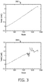
- FIG. 3 shows twist in radians plotted against node number where node number increases distally (to the right in the profile).
- Plot 302 shows an example of a normal twist profile
- plot 304 shows an erroneous twist profile that has been corrupted by vibration during the measurement.
- Shapes with a twist profile may be considered incorrect (an outlier) and are usually removed from the display (outlier rejection) in conventional systems.
- a very distal portion of the sensor e.g., 10-100 nodes or 0.8-8mm
- the data collected for this very distal portion of the shape measurement can be employed to detect and measure vibrations occurring at the tip of an interventional instrument (102).
- the tip vibrations can be caused by a mechanical interaction between the instrument and the vessel wall or surface.
- the operator often does not have tactile feedback from the instrument 102. In this case, it would be useful to know the interactions between the tip of the instrument 102 and the vessel wall. This could then be fed back to the operator as a 'vibration' felt in a robotic controller (e.g., actuation module 140).
- a robotic control loop can consider the amount of tip vibration in the positioning and distal shape of the instrument.
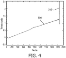
- a twist profile or curve 308 shows twist in radians plotted against node number where node number increases distally.
- Curve 308 shows a shape corrupted by vibration at the distal tip region during the measurement where the tip experiences tip vibration through wall contact during navigation. Note that there are observable discontinuities 310 in the distal nodes of the sensor.
- the tip vibration metric ( tvm ) is computed using Equation (1), where ⁇ is the twist in radians, i is the node along the fiber and end is the number of nodes in the fiber (1858 in the example of FIG. 4 ).
- the algorithm tests the last 10 nodes of the fiber and uses the maximum jump in twist to identify a potential vibration. Twist is derived from the average phase difference of outer fiber cores normalized by a central fiber core of the OSS system, and therefore any algorithms described for the twist metric can also be applied to the phase difference from one or more cores. Referring to FIG. 5 , the algorithm of Equation (1) was applied to 3 datasets. The datasets included:
- a tip vibration metric (tvm) was computed for the three datasets and was respectively plotted in plots 402, 404 and 406. Shapes that had twist error in the proximal part of the shape were excluded from this analysis to only focus on the vibrations in the tip region. In the dataset with no tip scraping inside the phantom (Dataset 1), the tvm of plot 402 is very low during navigation. In the dataset with wall scraping inside the phantom (Dataset 2), there are clearly a greater number of large jumps in the tip vibration in plot 404. The interior of the phantom in this simulation was very smooth, hard plastic. In plot 406, the tip of the device was pulled across a skin surface, and there is a significant increase in the tvm. The percentage of shapes that exceeded a tvm threshold during a specific time interval (2 seconds), for example, could be reported to the operator for feedback on the amount of vibration experienced at the tip of the device. Other criteria and thresholds may also be employed.
- twist frequency components may be employed as another way of detecting surface contact between the instrument 102 and the wall of a lumen.
- a method of detecting vibration at the tip / distal section of the instrument 102 and, in turn, wall scraping, is by making use of dampening along the length of the instrument 102.
- a high frequency vibration indicated by discontinuities 310 is observed at the tip. This vibration can propagate, as a longitudinal wave, along the length of the device, while getting dampened as it travels further.
- the amplitude and frequency of the vibration, as well as the rate of dampening vary and can be written as functions of the amplitude of the contact with the vessel wall, the duration of the scraping along the wall, the properties of the device such as its weight, structure, mechanical and material properties and so on.
- the amount of dampening can be employed to quantify the amount, duration and nature of the wall instrument interaction.
- the twist plot of FIG. 4 shows a higher frequency component at the distal tip, with this frequency reduction showing dampening of vibration along the length of the device.
- Another related way of picking up vibration is by evaluating the frequency of the twist signal near the tip of the instrument 102.
- the frequency of the distal section will be greater than the proximal portion.
- the frequency is expected to decrease along the length (from the tip towards the proximal region), and, using this scheme, vibration due to wall scraping can be distinguished from changes in twist due to other reasons such as problems with the termination and torqueing of the device.
- the distinguished signal can be employed to quantify the amount, duration and nature of the surface-instrument interaction.
- axial tension may be measured and employed.
- an axial tension signal is obtained during shape reconstruction. If the tip of the instrument 102 touches the wall, the interaction can result in a small compression at the tip. This contact can be determined from the optical sensing signal. If the tip touches the wall at an angle, a component of the force that is in an axial direction (along the direction of the fiber/instrument) will be observed in an axial tension signal and this could be used to determine wall scraping.
- temperature can be used to identify contact with a warm or cold surface. Temperature can be extracted from the optical shape sensing parameters through the central core of the fiber. A temperature indicator is particularly relevant for applications in which a device is used outside the body to make contact with the skin surface.
- specific curvatures of the instrument 102 may be used to identify surface contact. Tip wall scraping can induce a small curvature in the distal portion of the sensor (104) and can indicate that the device is in contact with the vessel wall, as shown, e.g., in FIG. 2 . This is primarily relevant for manual non-actuated devices where a small radius of curvature of the instrument 102 can only be the result of external mechanical interactions with the anatomy, etc.
- a motion profile may be employed to identify wall/instrument interaction.
- Wall scraping may be detected by observing the displacement, velocity and acceleration patterns (motion profile) of the OSS signal. Scraping of the tip of the instrument 102 is likely to cause sudden accelerations/decelerations of the distal portion of the instrument 102.
- This method may employ algorithms used to distinguish accelerations/decelerations due to normal handling with accelerations/decelerations due to wall scraping. This can be done by comparing acceleration/deceleration patterns at the tip (or portion in contact with the vessel wall) against other portions of the fiber that are not in contact with the vessel wall.
- Characterization data may be stored for comparison for use by the interaction evaluation module 148 ( FIG. 1 ). When the motion profile is measured, it can be compared with the characterization data to determine whether an interaction has occurred and the type of interaction.
- the interaction evaluation module 148 may include models and/or composite metric modules 136 employed to interpret and combine measured results received from the shape sensing system 104.
- a composite metric may be employed, which includes a combination of vibration and curvature detection measurements. These measurements may be combined in different ways including weighting the contributions from each to achieve a more accurate interaction determination and characterization. For example, each method employed for characterizing wall/instrument interactions may be given a score and the score may be weighted based on importance so that an overall score is derived. The overall score can be employed to compare against thresholds to identify the interaction. Based on the overall score or one or more individual scores, the interaction evaluation module 148 may be employed to make recommendations as the type and severity of the wall scraping or interaction.
- recommendations may be made on how to minimize or reduce the wall scraping or interactions. For example, if an axial stress is sensed at the distal tip, the interaction evaluation module 148 may make a recommendation to straighten the instrument 102 to reduce this type of interaction. These actions may be performed by the actuation module 140.
- the recommendations may be made based upon an indexed data storage system or relational database 138.
- the score can be referenced in the database 138 to determine a recommended action.
- the recommended action may include pre-stored text, which can be displayed on the display 118, the data may be processed using a model or formula to output a specific action (e.g., "twist 30 degrees clockwise", etc.) or actions may be carried out by the actuation module 140.
- the score and recommendation can be based on the type of procedure, the known position of the device within the body using optical shape sensing and/or other imaging information (e.g., x-ray, CT, MRI, endoscopy, etc.).
- known positions of the instruments (102) with respect to each other can be employed by the interaction evaluation module 148 to identify the more distally extended instrument that is more likely to be making contact with the vessel wall. Changes in the stiffness of the vessel wall will result in different 'vibration signatures' as the tip scrapes over the surface.
- Mechanical properties can be inferred by changes in the vibration of the tip as it passes from stiff tissue to a soft tissue, for example. In this case, the stiff tissue could be caused by stenosis and tip scraping would result in higher frequency vibrations than when scraping over the softer, healthy tissue region. Thus, the location of stenotic regions could be identified and indicated to the operator in real time.
- Such vibration patterns can be specific to the instrument 102 (different for guide wires and catheters) and this difference can be further used to identify the properties/texture/tissue-type of the region.
- stenotic regions could be matched to known stenotic regions identified from pre- or intra-operative imaging. This could be used to improve the registration between the shape sensing instrument and model being used for navigation purposes.
- the detection of tip scraping data to images and navigation models may be employed to provide other benefits as well. For example, positions of detected wall scrapings (from OSS fibers) may be employed to register vessel walls in stored or live images. In another example, the images may be employed to verify OSS data indicating wall contact.
- the present principles may be employed to turn the distal portion of OSS system 104 into a tip sensor.
- the change in vibration signature of the distal portion may be employed to identify the position of a stent within a vessel either prior to full deployment or after deployment.
- the vibration signature from the stent graft material would provide a different signature to the vascular wall on either side.
- the location of a fenestration within a stent graft would be detectable due an abrupt change in vibration signature.
- Imaging information from the imaging system 110 may be employed to identify when the device tip touches the wall of a vessel.
- the imaging information may be mapped with the OSS information (e.g., twist, frequency of twist, dampening, axial strain, etc.), and a pattern or event (per vessel/device/individual) can be recorded using the combined data (image and OSS).
- the combined data may be employed to build a database. By building a database or using this information a priori , patterns of when tip wall scraping occurs can be obtained for given portions of a procedure. These patterns may be employed and stored in the database 138 to provide predictive tools for determining a likely portion of a procedure when wall scraping may occur.
- the database 138 can provide warning messages corresponding with the points in the procedure where greater care should be taken.
- the combined data (image and OSS) can also be applied as a search criterion to determine the instances of tip wall scraping.
- another way to determine wall scraping is by using dampened vibration.
- a certain input vibration may be applied to the instrument 102 during navigation. This may be of a known pattern, amplitude, or frequency. This vibration would be transmitted (with some dampening) to the distal tip of the instrument 102, and any change in this pattern (point dampening for instance) would mean that the tip of the device has come in contact with the vessel wall.
- the input vibration may be the natural vibration of a robotic actuator that is manipulating the elongated device, such as, a catheter.
- the vibration may be imparted by the clinician during normal handling and navigation.
- the frequency of the vibrations, as well as the differential of the twist signal, among others could be employed to predict the position and time of contact of the device with the vessel wall.
- the present principles apply to a wide variety of applications including any integration of optical shape sensing technology into medical devices or other instruments for navigation in the body (e.g., endoscopes, bronchoscopes, catheters, guide wires, etc.) or through mechanical systems. This includes robotic and non-robotic use cases.
- the present principles find utility in non-medical applications, e.g., identifying when an instrument is making contact with a wall or a surface.
- the present principles apply to OSS systems that employ any scatter or reflective phenomena, e.g., Rayleigh (enhanced and regular) as well as Fiber Bragg implementations of shape sensing fiber.
- shape sensing feedback is received from a flexible shape sensing enabled instrument configured to pass along a surface.
- the vessel may include any lumen, organ, surface, wall, skin, bone, muscle or mechanical component or volume.
- shape sensing feedback is evaluated using an interaction evaluation module configured to monitor the shape sensing feedback from the instrument to determine modes of the shape sensing feedback that identify whether contact is made with a surface or wall of a vessel.
- the evaluation may include one or more different parameters as will be illustratively described.
- Evaluating the shape sensing feedback may include evaluating vibrations identified by discontinuity information in the optical shape sensing signal in block 506, or evaluating vibrations identified by frequency response information (e.g., damping response changes, etc.) in the optical shape sensing signal in block 508.
- Evaluating the shape sensing feedback may include identifying compression (e.g., axial strain) in the optical shape sensing signal at a distal end portion of the instrument in block 512, predicting contact between the instrument and the surface based on stored information (e.g., models, metrics, prediction data, etc.) in block 514 or determining and/or comparing a motion profile or images with stored data to determine whether contact is made between the instrument and the surface in block 516.
- OSS data may be compared to images, or images may be compared to OSS data to provide registration between the coordinate systems, or to verify contact with a surface, etc.
- evaluating the shape sensing feedback may include identifying temperature differences (e.g., axial strain) in the optical shape sensing signal at a distal end portion of the instrument.
- evaluating the shape sensing feedback may include identifying known curvatures in the optical shape sensing instrument.
- a representation e.g., an image (stored or live), model, etc.
- the comparison may be to determine whether surface contact has occurred or to identify a position where surface contact has occurred between the instrument and the surface.
- the images and the OSS data may be registered to determine if contact has occurred, or contact may be verified by registering the contact position with a boundary or vessel wall.
- the OSS contact may be employed as a criterion to register the vessel wall or boundary.
- Block 522 may be performed independently for registration, navigation, data collection, etc. of the instrument relative to the surface, as needed.
- a composite metric may optionally be computed and is configured to determine interaction between the instrument and the surface using two or more parameters of the shape sensing feedback, e.g., two or more of the parameters of blocks 506-522. Other parameters may also be employed instead of or in addition to those included in blocks 506-522.
- the two or more parameters of the composite metric may include a combination of vibrational information of the instrument, axial strain of the instrument, curvature of the instrument, temperature, motion patterns of the instrument, etc.
- results are reported.
- a type and magnitude of interaction between the instrument and the wall may be indicated to a user. This may include directions, actions or other information on how to avoid or reduce such contact, or simply provide real-time feedback in which the user can discontinue a present task or action to reduce wall scraping or the like.
Landscapes
- Health & Medical Sciences (AREA)
- Surgery (AREA)
- Life Sciences & Earth Sciences (AREA)
- Engineering & Computer Science (AREA)
- Public Health (AREA)
- General Health & Medical Sciences (AREA)
- Veterinary Medicine (AREA)
- Nuclear Medicine, Radiotherapy & Molecular Imaging (AREA)
- Animal Behavior & Ethology (AREA)
- Biomedical Technology (AREA)
- Heart & Thoracic Surgery (AREA)
- Medical Informatics (AREA)
- Molecular Biology (AREA)
- General Physics & Mathematics (AREA)
- Pathology (AREA)
- Physics & Mathematics (AREA)
- Oral & Maxillofacial Surgery (AREA)
- Robotics (AREA)
- Endoscopes (AREA)
- Optical Transform (AREA)
Description
- This disclosure relates to medical instruments and more particularly to shape sensing optical fibers employed in detecting interactions with surfaces.
- Optical shape sensing (OSS) uses light along a multicore optical fiber for device localization and navigation during surgical intervention. One principle involved makes use of distributed strain measurement in the optical fiber using characteristic Rayleigh backscatter or controlled grating patterns. The shape along the optical fiber begins at a specific point along the sensor, known as the launch or z = 0 and extends to the tip of the fiber. For clinical use, the shape sensing fiber is integrated into a medical device, such as a catheter, guide wire, endoscope, robotic tool, etc. This is typically done by placing the fiber into a lumen within the wall of the device.
- Multiple shape parameters are provided from a reconstruction of the shape sensing data. These parameters include x, y, z position, axial strain, and twist, among others. Ultimately, all of these parameters are derived from measurements of the phase from multiple cores (for example, 4 cores) within a shape sensing fiber. The shape sensing measurement uses data from a range of illumination frequencies (for example, 20nm) that are swept using an input light source. This needs some finite amount of time (for example, 1-10ms) to perform a measurement. During that time, changes in the phase in the cores can lead to an incorrect reading and corresponding incorrect shape reconstruction. During navigation, these incorrect shapes are typically detected and removed. Since the twist is an average of the three outer cores normalized by the central core, it provides an aggregate of the phase in all of the cores. It is also know to retrieve force components from optical sensing data (
US8622935 andWO2007/015139 ). - In endovascular procedures, there is a risk of producing embolic particles due to the scraping of the interventional devices during navigation. These embolic particles that are dislodged during navigation may lead to adverse conditions, such as clots in other regions of the vasculature. Clots may in turn lead to adverse events such as stroke. It is difficult for operators to know how much contact the tip of the device is making with the vessel wall during navigation.
- The invention is solely defined by the appended claims. Further examples that are not encompassed in the scope of the claims, even if they are indicated as "embodiments of the invention" in the description, are not part of the invention. In accordance with the present principles, a system for detecting instrument interaction with a surface includes a shape sensing enabled instrument configured to pass along the surface. An interaction evaluation module is configured to monitor shape sensing feedback from the instrument to determine modes of the shape sensing feedback that identify whether contact is made with the surface and to determine the position of the contact.
- A system for detecting instrument interaction with a surface includes a flexible instrument configured to pass along a surface. An optical shape sensing system is integrated into the instrument and configured to provide an optical shape sensing signal as shape sensing feedback. A processor and memory coupled to the processor are included. An interaction evaluation module is stored in the memory and configured to monitor the shape sensing feedback from the instrument to determine modes of the shape sensing feedback that identify whether contact is made with the surface. An actuation module is configured to adjust the instrument in accordance with the modes of the shape sensing feedback.
- A method for detecting instrument interaction with a surface includes receiving shape sensing feedback from a flexible shape sensing enabled instrument configured to pass along the surface; and evaluating the shape sensing feedback using an interaction evaluation module configured to monitor the shape sensing feedback from the instrument to determine modes of the shape sensing feedback in order to identify whether contact is made with the surface and to determine the position of the contact.
- These and other objects, features and advantages of the present disclosure will become apparent from the following detailed description of illustrative embodiments thereof, which is to be read in connection with the accompanying drawings.
- This disclosure will present in detail the following description of preferred embodiments with reference to the following figures wherein:
-
FIG. 1 is a block/flow diagram showing a shape sensing system which employs an interaction evaluation module for detecting whether contact has been made by an instrument with a wall of a vessel in accordance with one embodiment; -
FIG. 2 shows two examples of instrument-to-vessel wall interactions; -
FIG. 3 shows two twist profile plots showing a normal twist profile and an erroneous twist profile due to vibrational disturbance; -
FIG. 4 shows a twist profile plot showing a distal tip region of the signal corrupted by vibrational disturbance; -
FIG. 5 shows a tip vibration metric (tvm) plotted against frame number for three datasets whereDataset 1 shows no tip scraping inside a phantom,Dataset 2 shows wall scraping inside the phantom andDataset 3 shows tip scraping against skin in accordance with the present principles; and -
FIG. 6 is a block/flow diagram showing a method for detecting whether contact has been made by an instrument with a wall or surface in accordance with illustrative embodiments. - In accordance with the present principles, systems and methods are disclosed to identify when a part of the interventional device has made contact with a surface, such as, a vessel wall, a surface of the skin, a heart, a bone, a non-biological surface, etc. Such techniques may preferably employ an optical shape sensing signal, but multiple approaches may be employed. In some embodiments, a combination of techniques including but not limited to optical shape sensing may be employed to provide a meaningful representation of surface contact or wall scraping. Wall scraping information can be extracted from the optical shape sensing signals in a plurality of ways. These may include, e.g., identifying the presence of vibrations through discontinuities in a twist signal, identifying the presence of vibrations through frequency components of the twist signal, detecting compression at the tip of the device from an axial strain signal, predicting wall contact from the shape of a device - specifically high curvature in a distal section, using a motion profile of the device to isolate signals indicating contact, etc.
- Navigation of medical devices into target vessels may be achieved using pre-curved catheters and guidewires, which interact with each other and the vascular wall. This interaction with the vascular wall can lead to the creation of embolic particles that are dislodged during navigation. Such particles can result in clots in other regions of the vasculature, leading to adverse events such as stroke. In conventional scenarios, it is difficult for operators to know how much contact the tip of the device is making with the vessel wall during navigation since the devices are manipulated from outside the body and any highfrequency vibrations induced by the tip contact are dampened out before being sensed by the operator. Further, in robotic procedures where the operator no longer has tactile feedback from the device, it is especially important to know the interactions between the tip of the device and the vessel wall.
- Vibrations occurring during an optical shape sensing measurement are acquired within the shape sensing parameters. For example, a twist parameter tends to show discontinuities and spikes in the presence of vibration. These vibrations can be spatially localized along the length of the sensor. Similarly, vibration can manifest itself as a broadening of the termination reflection measured in the fiber. Another shape parameter, curvature, can indicate contact with the wall when the radius of curvature becomes very small in the distal portion of the device. By inspecting the shape sensing data for manifestation of these and other features in accordance with the present principles, it is possible to quantify the amount of wall scraping occurring during navigation. In the case of manual operation, this value could be reported to the operator.
- For robotic operation, this information could be part of the control loop to encourage an alternative position or shape for the distal part of the device. For example, an actuation module may be employed that employs information about a shape sensing enabled instrument to determine, e.g., when the instrument is making contact with the vessel wall and reduce or prevent such contact, to predict when the contact is going to be made and lower its impact (force), to determine whether sufficient contact is being made with a surface, such as the surface of a bone or skin to paint a feature for an orthopedic application like total knee replacement or other procedure (for example, when scraping tissue, the present principles can determine if bone has been contacted versus skin or muscle, etc.).
- It should be understood that the present invention will be described in terms of medical instruments; however, the teachings of the present invention are much broader and are applicable to any fiber optic instruments. In some embodiments, the present principles are employed in tracking or analyzing complex biological or mechanical systems. In particular, the present principles are applicable to internal tracking procedures of biological systems, procedures in all areas of the body such as the lungs, gastro-intestinal tract, excretory organs, blood vessels, etc. The elements depicted in the FIGS. may be implemented in various combinations of hardware and software and provide functions which may be combined in a single element or multiple elements.
- The functions of the various elements shown in the FIGS. can be provided through the use of dedicated hardware as well as hardware capable of executing software in association with appropriate software. When provided by a processor, the functions can be provided by a single dedicated processor, by a single shared processor, or by a plurality of individual processors, some of which can be shared. Moreover, explicit use of the term "processor" or "controller" should not be construed to refer exclusively to hardware capable of executing software, and can implicitly include, without limitation, digital signal processor ("DSP") hardware, read-only memory ("ROM") for storing software, random access memory ("RAM"), non-volatile storage, etc.
- Moreover, all statements herein reciting principles, aspects, and embodiments of the invention, as well as specific examples thereof, are intended to encompass both structural and functional equivalents thereof. Additionally, it is intended that such equivalents include both currently known equivalents as well as equivalents developed in the future (i.e., any elements developed that perform the same function, regardless of structure). Thus, for example, it will be appreciated by those skilled in the art that the block diagrams presented herein represent conceptual views of illustrative system components and/or circuitry embodying the principles of the invention. Similarly, it will be appreciated that any flow charts, flow diagrams and the like represent various processes which may be substantially represented in computer readable storage media and so executed by a computer or processor, whether or not such computer or processor is explicitly shown.
- Furthermore, embodiments of the present invention can take the form of a computer program product accessible from a computer-usable or computer-readable storage medium providing program code for use by or in connection with a computer or any instruction execution system. For the purposes of this description, a computer-usable or computer readable storage medium can be any apparatus that may include, store, communicate, propagate, or transport the program for use by or in connection with the instruction execution system, apparatus, or device. The medium can be an electronic, magnetic, optical, electromagnetic, infrared, or semiconductor system (or apparatus or device) or a propagation medium. Examples of a computer-readable medium include a semiconductor or solid state memory, magnetic tape, a removable computer diskette, a random access memory (RAM), a read-only memory (ROM), a rigid magnetic disk and an optical disk. Current examples of optical disks include compact disk - read only memory (CD-ROM), compact disk - read/write (CD-R/W), Blu-Ray™ and DVD.
- Referring now to the drawings in which like numerals represent the same or similar elements and initially to
FIG. 1 , asystem 100 for detecting surface contact using shape sensing enabled instruments is illustratively shown in accordance with one embodiment.System 100 may include a workstation or console 112 from which a procedure is supervised and/or managed.Workstation 112 preferably includes one ormore processors 114 andmemory 116 for storing programs and applications.Memory 116 may store anoptical sensing module 115 configured to interpret optical feedback signals from a shape sensing device orsystem 104.Optical sensing module 115 is configured to use the optical signal feedback (and any other feedback, e.g., electromagnetic (EM) tracking) to reconstruct deformations, deflections and other changes associated with a medical device or instrument (shape sensing enabled instrument) 102 and/or its surrounding region. Themedical instrument 102 may include a catheter, a guidewire, a probe, an endoscope, a robot, an electrode, a filter device, a balloon device, a pointer, or other medical component, etc. - The
shape sensing system 104 oninstrument 102 may include one or more optical fibers 126 which are coupled to theinstrument 102 in a set pattern or patterns. The optical fibers 126 connect to theworkstation 112 throughcabling 127. Thecabling 127 may include fiber optics, electrical connections, other instrumentation, etc., as needed. Thecabling 127 interfaces with anoptical interrogation unit 108 that may include or work with an optical source or sources 106. Theinterrogation unit 108 sends and receives optical signals from theshape sensing system 104. -
Shape sensing system 104 with fiber optics may be based on fiber optic Bragg grating sensors. A fiber optic Bragg grating (FBG) is a short segment of optical fiber that reflects particular wavelengths of light and transmits all others. This is achieved by adding a periodic variation of the refractive index in the fiber core, which generates a wavelength-specific dielectric mirror. A fiber Bragg grating can therefore be used as an inline optical filter to block certain wavelengths, or as a wavelength-specific reflector. - Inherent backscatter in conventional optical fiber can be exploited for optical shape sensing (OSS). One such approach uses Rayleigh scatter (or other scattering) in standard single-mode communications fiber. Rayleigh scatter occurs as a result of random fluctuations of the index of refraction in the fiber core. These random fluctuations can be modeled as a Bragg grating with a random variation of amplitude and phase along the grating length. By using this effect in three or more cores running within a single length of multi-core fiber, the 3D shape and dynamics of the surface of interest can be followed.
- Fiber Bragg Gratings (FBGs) may also be employed for OSS, which use Fresnel reflection at each of the interfaces where the refractive index is changing. For some wavelengths, the reflected light of the various periods is in phase so that constructive interference exists for reflection and, consequently, destructive interference for transmission. The Bragg wavelength is sensitive to strain as well as to temperature. This means that Bragg gratings can be used as sensing elements in fiber optic sensors. In an FBG sensor, the measurand (e.g., strain) causes a shift in the Bragg wavelength.
- One advantage of OSS is that various sensor elements can be distributed over the length of a fiber. Incorporating three or more cores with various sensors (gauges) along the length of a fiber that is embedded in a structure permits a three-dimensional form of such a structure to be precisely determined with high accuracy. Along the length of the fiber, at various positions, a multitude of FBG sensors can be located (e.g., 3 or more fiber sensing cores). From the strain measurement of each FBG, the curvature of the structure can be inferred at that position. From the multitude of measured positions, the total three-dimensional form is determined.
- In one embodiment, the
optical sensing module 115 includes aninteraction evaluation module 148. Data collected from theOSS device 104 is interpreted to evaluate an amount of wall interaction/contact made by theinstrument 102 using theOSS device 104 feedback. The wallinteraction evaluation module 148 may focus on one or more different parameters to measure the duration, force, severity, or magnitude of the interaction, etc. made by theinstrument 102 and a vessel or organ wall in a volume 131 where theinstrument 102 is deployed. The surfaceinteraction evaluation module 148 is configured to receive feedback from theshape sensing device 104 and record position and orientation data as to where thesensing device 104 has been within the volume 131. Position (and orientation) data or other data from theshape sensing device 104 within the space or volume 131 can be displayed on adisplay device 118.Workstation 112 includes thedisplay 118 for viewinginternal images 134 of a subject (patient) 160 or volume 131 and may include theimage 134 as an overlay or other rendering of the positions of theshape sensing device 104 on images collected by animaging device 110. Theimaging device 110 may include any imaging system.Display 118 may also permit a user to interact with theworkstation 112 and its components and functions, or any other element within thesystem 100. This is further facilitated by aninterface 120 which may include a keyboard, a mouse, a joystick, a haptic device, or any other peripheral or control to permit user feedback from and interaction with theworkstation 112. - The wall
interaction evaluation module 148 evaluates clinically useful data to determine when, where and how much surface interaction (e.g., wall scraping) takes place during a procedure. In particularly useful embodiments, techniques employed to identify when a part of theinterventional instrument 102 has made contact with a surface (e.g., a vessel wall, skin, bone, organ or vessel wall scraping) can be extracted from the optical shape sensing signals of theOSS system 104. The techniques may include identifying the presence of vibrations through discontinuities in a twist signal, identifying the presence of vibrations through frequency components of the twist signal, and/or detecting compression at the tip of theinstrument 102 from the axial strain signal. Other techniques include predicting wall contact from the shape of the device. This may include determining high curvature in the distal section of theinstrument 102 or other shapes depending on the physical constraints and conditions. In other embodiments, the motion profile of theinstrument 102 may be employed to understand when wall interaction has occurred. - The wall
interaction evaluation module 148 includes models, algorithms, formulas, etc. that look at specific data to understand when portions of theinstrument 102 engage the walls or surfaces of the volume 131 using the OSS signal of the OSS device orsystem 104. When the wallinteraction evaluation module 148 determines that engagement has occurred, the severity and duration of the engagement may be evaluated using the data. The data may be compared against acceptable thresholds and be employed to provide guidance to the user during a procedure. For example, if too much wall interaction is measured, there may be an obstruction or other issue and the procedure may be terminated or theinstrument 102 withdrawn. In other embodiments, other actions may be taken preferably in accordance with the guidance provided from theinteraction evaluation module 148 to the user. - In one embodiment, where computer-aided or robotic assistance is employed, information employed by the
interaction evaluation module 148 could be used as part of the control loop to encourage an alternative position or shape for a part of the instrument 102 (e.g., the distal end portion). For example, anactuation module 140 may be employed to control motion or shape of theinstrument 102. Theactuation module 140 employs information provided by the shape sensing enabledinstrument 102 to determine, e.g., when theinstrument 102 is making contact with a surface or vessel wall, and to reduce or prevent such contact (e.g., change the shape of the instrument 102). Theactuation module 140 may provide feedback (e.g., vibration, light, audible alarm, etc.) to a user that surface contact has been made or that surface contact exceeding a threshold (e.g., force threshold) has been made. In another embodiment, theactuation module 140 may be employed to alter the position or use of the instruments due to a prediction as to when contact is going to be made (by the interaction evaluation module 148). Predictions may be made using prior data inmodels 136, etc. Theactuation module 140 would than attempt to lower its impact (force) by changing direction, reducing speed, etc. Theactuation module 140 may be employed as a sensor to determine whether sufficient or significant contact is being made with a surface, such as the surface of a bone or skin, e.g., to paint a feature for an orthopedic application like total knee replacement or other procedure. - The
actuation module 140 may include hardware systems configured to advance or retract the instrument at defined displacements, velocities and/or accelerations. Theactuation module 140 may include robotic control mechanisms, such as actuators, servos, pneumatics, etc. - Referring to
FIG. 2 , examples 200 and 201 of a shape sensing enabledinstrument 102 in ablood vessel 202 are depicted to demonstrate tip interaction with internal surfaces of theblood vessel 202. In example 200, theinstrument 102 is pulled back along thevessel 202 in the direction of arrow "A". Atip 204 scrapes against aplaque 206. To prevent embolic particles from being dislodged into the blood stream, the present principles are employed to determine whether surface contact is being made. In example 201, theinstrument 102 is advanced up thevessel 202 in the direction of arrow "B". Thetip 204 is bent back by the contact with thevessel wall 202. This also causes interaction with the plaque, and the potential dislodgement of particles into the blood stream. In both examples 200 and 201, the shape and configuration of thedevice 102 may be employed to determine the surface interaction. Surface interaction can be determined by identifying the presence of vibrations through discontinuities in the twist signal or through frequency components of the twist signal, curvature detection, motion profile and/or detecting compression at thetip 204 of theinstrument 102 from the axial strain signal. Other techniques may also be employed, e.g., wall contact prediction from the shape of the instrument (e.g., high curvature in the distal section, etc.). - Referring to
FIG. 3 , a twist profile provides an amount of twist in the OSS system 104 (and therefore the instrument 102).FIG. 3 shows twist in radians plotted against node number where node number increases distally (to the right in the profile). When the tip of theinstrument 102 comes in contact with a wall or surface and is scraped along it, there can be a vibration imparted onto the tip of theinstrument 102. This vibration is typically isolated to the distal portion of the OSS shape sensor and results in an incorrect measurement in that region. Plot 302 shows an example of a normal twist profile, andplot 304 shows an erroneous twist profile that has been corrupted by vibration during the measurement. Shapes with a twist profile may be considered incorrect (an outlier) and are usually removed from the display (outlier rejection) in conventional systems. In many cases, a very distal portion of the sensor (e.g., 10-100 nodes or 0.8-8mm) is omitted from this type of outlier detection since it is typically sensitive to corruption by vibrations and can lead to an excessive rejection of clinically-useful data, especially since it does not contribute to the majority of the shape. In accordance with the present principles, the data collected for this very distal portion of the shape measurement can be employed to detect and measure vibrations occurring at the tip of an interventional instrument (102). - The tip vibrations can be caused by a mechanical interaction between the instrument and the vessel wall or surface. In robotic procedures, the operator often does not have tactile feedback from the
instrument 102. In this case, it would be useful to know the interactions between the tip of theinstrument 102 and the vessel wall. This could then be fed back to the operator as a 'vibration' felt in a robotic controller (e.g., actuation module 140). A robotic control loop can consider the amount of tip vibration in the positioning and distal shape of the instrument. - Referring to
FIG. 4 , a twist profile orcurve 308 shows twist in radians plotted against node number where node number increases distally.Curve 308 shows a shape corrupted by vibration at the distal tip region during the measurement where the tip experiences tip vibration through wall contact during navigation. Note that there areobservable discontinuities 310 in the distal nodes of the sensor. - To detect that the tip is experiencing vibration, a number of algorithms may be employed. For example, a threshold on the differential of the distal part of the twist, as shown below, may be employed:

- The tip vibration metric (tvm) is computed using Equation (1), where θ is the twist in radians, i is the node along the fiber and end is the number of nodes in the fiber (1858 in the example of
FIG. 4 ). The algorithm tests the last 10 nodes of the fiber and uses the maximum jump in twist to identify a potential vibration. Twist is derived from the average phase difference of outer fiber cores normalized by a central fiber core of the OSS system, and therefore any algorithms described for the twist metric can also be applied to the phase difference from one or more cores. Referring toFIG. 5 , the algorithm of Equation (1) was applied to 3 datasets. The datasets included: - Dataset 1: Navigation with a catheter in a vascular phantom (hard plastic used as a simulation) with no contact between the tip and the vessel wall. The tip of the catheter is free floating in the phantom vessel during navigation.
- Dataset 2: Navigation with a catheter in the vascular phantom (e.g., hard plastic) with contact between the tip and the vessel wall. The tip of the catheter makes contact with the phantom wall during navigation.
- Dataset 3: Manually dragging the tip of the catheter along a skin surface (palm of a hand).
- A tip vibration metric (tvm) was computed for the three datasets and was respectively plotted in
plots plot 402 is very low during navigation. In the dataset with wall scraping inside the phantom (Dataset 2), there are clearly a greater number of large jumps in the tip vibration inplot 404. The interior of the phantom in this simulation was very smooth, hard plastic. Inplot 406, the tip of the device was pulled across a skin surface, and there is a significant increase in the tvm. The percentage of shapes that exceeded a tvm threshold during a specific time interval (2 seconds), for example, could be reported to the operator for feedback on the amount of vibration experienced at the tip of the device. Other criteria and thresholds may also be employed. - Referring again to
FIG. 4 , twist frequency components may be employed as another way of detecting surface contact between theinstrument 102 and the wall of a lumen. A method of detecting vibration at the tip / distal section of theinstrument 102 and, in turn, wall scraping, is by making use of dampening along the length of theinstrument 102. When the tip of the device comes in contact with the vessel wall, a high frequency vibration indicated bydiscontinuities 310 is observed at the tip. This vibration can propagate, as a longitudinal wave, along the length of the device, while getting dampened as it travels further. The amplitude and frequency of the vibration, as well as the rate of dampening, vary and can be written as functions of the amplitude of the contact with the vessel wall, the duration of the scraping along the wall, the properties of the device such as its weight, structure, mechanical and material properties and so on. Once characterized, the amount of dampening (or other properties) can be employed to quantify the amount, duration and nature of the wall instrument interaction. In this example, the twist plot ofFIG. 4 , during wall scraping, shows a higher frequency component at the distal tip, with this frequency reduction showing dampening of vibration along the length of the device. - Another related way of picking up vibration is by evaluating the frequency of the twist signal near the tip of the
instrument 102. The frequency of the distal section will be greater than the proximal portion. The frequency is expected to decrease along the length (from the tip towards the proximal region), and, using this scheme, vibration due to wall scraping can be distinguished from changes in twist due to other reasons such as problems with the termination and torqueing of the device. The distinguished signal can be employed to quantify the amount, duration and nature of the surface-instrument interaction. - In accordance with the present principles, other measurements may be made and employed to evaluate the occurrence, magnitude and duration on surface or wall interaction with an instrument. In one embodiment, axial tension may be measured and employed. In such a method for determining wall scraping, an axial tension signal is obtained during shape reconstruction. If the tip of the
instrument 102 touches the wall, the interaction can result in a small compression at the tip. This contact can be determined from the optical sensing signal. If the tip touches the wall at an angle, a component of the force that is in an axial direction (along the direction of the fiber/instrument) will be observed in an axial tension signal and this could be used to determine wall scraping. In another embodiment, temperature can be used to identify contact with a warm or cold surface. Temperature can be extracted from the optical shape sensing parameters through the central core of the fiber. A temperature indicator is particularly relevant for applications in which a device is used outside the body to make contact with the skin surface. - In another embodiment, specific curvatures of the
instrument 102 may be used to identify surface contact. Tip wall scraping can induce a small curvature in the distal portion of the sensor (104) and can indicate that the device is in contact with the vessel wall, as shown, e.g., inFIG. 2 . This is primarily relevant for manual non-actuated devices where a small radius of curvature of theinstrument 102 can only be the result of external mechanical interactions with the anatomy, etc. - In yet another embodiment, a motion profile may be employed to identify wall/instrument interaction. Wall scraping may be detected by observing the displacement, velocity and acceleration patterns (motion profile) of the OSS signal. Scraping of the tip of the
instrument 102 is likely to cause sudden accelerations/decelerations of the distal portion of theinstrument 102. This method may employ algorithms used to distinguish accelerations/decelerations due to normal handling with accelerations/decelerations due to wall scraping. This can be done by comparing acceleration/deceleration patterns at the tip (or portion in contact with the vessel wall) against other portions of the fiber that are not in contact with the vessel wall. Characterization data may be stored for comparison for use by the interaction evaluation module 148 (FIG. 1 ). When the motion profile is measured, it can be compared with the characterization data to determine whether an interaction has occurred and the type of interaction. - It should be understood that the description has been focused on the tip of the
instrument 102; however, all of the methods/techniques described are applicable to more proximal parts of theinstrument 102. It may be of interest to only identify vibrations that occur within the body as wall scraping, so knowing how much of the device is within the body is relevant. - Referring again to
FIG. 1 , theinteraction evaluation module 148 may include models and/or compositemetric modules 136 employed to interpret and combine measured results received from theshape sensing system 104. In one embodiment, a composite metric may be employed, which includes a combination of vibration and curvature detection measurements. These measurements may be combined in different ways including weighting the contributions from each to achieve a more accurate interaction determination and characterization. For example, each method employed for characterizing wall/instrument interactions may be given a score and the score may be weighted based on importance so that an overall score is derived. The overall score can be employed to compare against thresholds to identify the interaction. Based on the overall score or one or more individual scores, theinteraction evaluation module 148 may be employed to make recommendations as the type and severity of the wall scraping or interaction. In one embodiment, recommendations may be made on how to minimize or reduce the wall scraping or interactions. For example, if an axial stress is sensed at the distal tip, theinteraction evaluation module 148 may make a recommendation to straighten theinstrument 102 to reduce this type of interaction. These actions may be performed by theactuation module 140. - The recommendations may be made based upon an indexed data storage system or
relational database 138. When an overall score or individual score is computed, the score can be referenced in thedatabase 138 to determine a recommended action. The recommended action may include pre-stored text, which can be displayed on thedisplay 118, the data may be processed using a model or formula to output a specific action (e.g., "twist 30 degrees clockwise", etc.) or actions may be carried out by theactuation module 140. The score and recommendation can be based on the type of procedure, the known position of the device within the body using optical shape sensing and/or other imaging information (e.g., x-ray, CT, MRI, endoscopy, etc.). - In the case where multiple shape sensed devices are used together, known positions of the instruments (102) with respect to each other can be employed by the
interaction evaluation module 148 to identify the more distally extended instrument that is more likely to be making contact with the vessel wall. Changes in the stiffness of the vessel wall will result in different 'vibration signatures' as the tip scrapes over the surface. Mechanical properties can be inferred by changes in the vibration of the tip as it passes from stiff tissue to a soft tissue, for example. In this case, the stiff tissue could be caused by stenosis and tip scraping would result in higher frequency vibrations than when scraping over the softer, healthy tissue region. Thus, the location of stenotic regions could be identified and indicated to the operator in real time. Such vibration patterns can be specific to the instrument 102 (different for guide wires and catheters) and this difference can be further used to identify the properties/texture/tissue-type of the region. - In addition, such stenotic regions could be matched to known stenotic regions identified from pre- or intra-operative imaging. This could be used to improve the registration between the shape sensing instrument and model being used for navigation purposes. The detection of tip scraping data to images and navigation models may be employed to provide other benefits as well. For example, positions of detected wall scrapings (from OSS fibers) may be employed to register vessel walls in stored or live images. In another example, the images may be employed to verify OSS data indicating wall contact.
- In other embodiments, the present principles may be employed to turn the distal portion of
OSS system 104 into a tip sensor. For example, the change in vibration signature of the distal portion may be employed to identify the position of a stent within a vessel either prior to full deployment or after deployment. In this embodiment, the vibration signature from the stent graft material would provide a different signature to the vascular wall on either side. Similarly, the location of a fenestration within a stent graft would be detectable due an abrupt change in vibration signature. - Imaging information from the
imaging system 110, such as an X-ray image or a video image, may be employed to identify when the device tip touches the wall of a vessel. The imaging information may be mapped with the OSS information (e.g., twist, frequency of twist, dampening, axial strain, etc.), and a pattern or event (per vessel/device/individual) can be recorded using the combined data (image and OSS). The combined data may be employed to build a database. By building a database or using this information a priori, patterns of when tip wall scraping occurs can be obtained for given portions of a procedure. These patterns may be employed and stored in thedatabase 138 to provide predictive tools for determining a likely portion of a procedure when wall scraping may occur. Thedatabase 138 can provide warning messages corresponding with the points in the procedure where greater care should be taken. The combined data (image and OSS) can also be applied as a search criterion to determine the instances of tip wall scraping. - In other embodiments, another way to determine wall scraping is by using dampened vibration. In such a case, a certain input vibration may be applied to the
instrument 102 during navigation. This may be of a known pattern, amplitude, or frequency. This vibration would be transmitted (with some dampening) to the distal tip of theinstrument 102, and any change in this pattern (point dampening for instance) would mean that the tip of the device has come in contact with the vessel wall. The input vibration may be the natural vibration of a robotic actuator that is manipulating the elongated device, such as, a catheter. In a non-robotic case, the vibration may be imparted by the clinician during normal handling and navigation. In both of these cases, the frequency of the vibrations, as well as the differential of the twist signal, among others, could be employed to predict the position and time of contact of the device with the vessel wall. - The present principles apply to a wide variety of applications including any integration of optical shape sensing technology into medical devices or other instruments for navigation in the body (e.g., endoscopes, bronchoscopes, catheters, guide wires, etc.) or through mechanical systems. This includes robotic and non-robotic use cases. In addition, the present principles find utility in non-medical applications, e.g., identifying when an instrument is making contact with a wall or a surface. The present principles apply to OSS systems that employ any scatter or reflective phenomena, e.g., Rayleigh (enhanced and regular) as well as Fiber Bragg implementations of shape sensing fiber.
- Referring to
FIG. 6 , a method for detecting instrument interaction with a vessel wall is shown and described. Inblock 502, shape sensing feedback is received from a flexible shape sensing enabled instrument configured to pass along a surface. The vessel may include any lumen, organ, surface, wall, skin, bone, muscle or mechanical component or volume. Inblock 504, the shape sensing feedback is evaluated using an interaction evaluation module configured to monitor the shape sensing feedback from the instrument to determine modes of the shape sensing feedback that identify whether contact is made with a surface or wall of a vessel. The evaluation may include one or more different parameters as will be illustratively described. - Evaluating the shape sensing feedback may include evaluating vibrations identified by discontinuity information in the optical shape sensing signal in
block 506, or evaluating vibrations identified by frequency response information (e.g., damping response changes, etc.) in the optical shape sensing signal inblock 508. Evaluating the shape sensing feedback may include identifying compression (e.g., axial strain) in the optical shape sensing signal at a distal end portion of the instrument inblock 512, predicting contact between the instrument and the surface based on stored information (e.g., models, metrics, prediction data, etc.) in block 514 or determining and/or comparing a motion profile or images with stored data to determine whether contact is made between the instrument and the surface inblock 516. OSS data may be compared to images, or images may be compared to OSS data to provide registration between the coordinate systems, or to verify contact with a surface, etc. Inblock 518, evaluating the shape sensing feedback may include identifying temperature differences (e.g., axial strain) in the optical shape sensing signal at a distal end portion of the instrument. Inblock 520, evaluating the shape sensing feedback may include identifying known curvatures in the optical shape sensing instrument. - In
block 522, a representation (e.g., an image (stored or live), model, etc.) of the surface may be configured for comparison with positions and orientations determined by the optical shape sensing of the instrument. The comparison may be to determine whether surface contact has occurred or to identify a position where surface contact has occurred between the instrument and the surface. The images and the OSS data may be registered to determine if contact has occurred, or contact may be verified by registering the contact position with a boundary or vessel wall. In another embodiment, the OSS contact may be employed as a criterion to register the vessel wall or boundary.Block 522 may be performed independently for registration, navigation, data collection, etc. of the instrument relative to the surface, as needed. - In block 524, a composite metric may optionally be computed and is configured to determine interaction between the instrument and the surface using two or more parameters of the shape sensing feedback, e.g., two or more of the parameters of blocks 506-522. Other parameters may also be employed instead of or in addition to those included in blocks 506-522. For example, the two or more parameters of the composite metric may include a combination of vibrational information of the instrument, axial strain of the instrument, curvature of the instrument, temperature, motion patterns of the instrument, etc.
- In
block 526, results are reported. A type and magnitude of interaction between the instrument and the wall may be indicated to a user. This may include directions, actions or other information on how to avoid or reduce such contact, or simply provide real-time feedback in which the user can discontinue a present task or action to reduce wall scraping or the like. - In interpreting the appended claims, it should be understood that:
- a) the word "comprising" does not exclude the presence of other elements or acts than those listed in a given claim;
- b) the word "a" or "an" preceding an element does not exclude the presence of a plurality of such elements;
- c) any reference signs in the claims do not limit their scope;
- d) several "means" may be represented by the same item or hardware or software implemented structure or function; and
- e) no specific sequence of acts is intended to be required unless specifically indicated.
- Having described preferred embodiments for detection of surface contact with optical shape sensing (which are intended to be illustrative and not limiting), it is noted that modifications and variations can be made by persons skilled in the art in light of the above teachings. It is therefore to be understood that changes may be made in the particular embodiments of the disclosure disclosed which are within the scope of the embodiments disclosed herein as outlined by the appended claims.
Claims (7)
- A system for detecting instrument interaction with a surface, comprising:a shape sensing enabled instrument (102) configured to pass along the surface and which includes an optical shape sensing system (104) configured to provide an optical shape sensing signal as the shape sensing feedback; andan interaction evaluation module (148) configured to monitor shape sensing feedback from the instrument to determine modes of the shape sensing feedback in order to identify whether contact is made with the surface and to determine the position of the contact, characterized in that the modes of shape sensing feedback include one or more of:vibrations identified by one or more of discontinuity information or frequency response information in the optical shape sensing signal;a shape configuration determined from the optical shape sensing signal indicating contact between the instrument (102) and the surface; anda motion profile determined from the optical shape sensing signal indicating contact between the instrument (102) and the surface.
- The system as claimed in claim 1, wherein the modes of the shape sensing feedback include vibrations occurring at a tip of the instrument (102) identified by one or more of discontinuity information or frequency response information in a twist profile representing the amount of twist along the instrument, said twist profile being derived from the optical shape sensing signal.
- The system as recited in claim 1 or 2, further comprising a composite metric (524) configured to determine interaction between the instrument and the surface using two or more of said modes of the shape sensing feedback.
- The system as recited in claim 1, further comprising a representation (134) of the surface configured for comparison with positions and orientations determined by the optical shape sensing of the instrument to determine whether surface contact has occurred or to identify a position where surface contact has occurred between the instrument and the surface.
- The system as recited in claim 1, further comprising an actuation module (140) configured to adjust the instrument in accordance with the modes of the shape sensing feedback that identify whether contact is made with the surface.
- The system as recited in claim 1, further comprising:a processor (114);memory (116) coupled to the processor and storing the interaction evaluation module (148); andan actuation module (140) configured to adjust the instrument (102) in accordance with the modes of the shape sensing feedback.
- A method for detecting instrument interaction with a surface, comprising:receiving (502) shape sensing feedback from a flexible shape sensing enabled instrument configured to pass along the surface and which includes an optical shape sensing system (104) configured to provide an optical shape sensing signal as the shape sensing feedback; andevaluating (504) the shape sensing feedback using an interaction evaluation module configured to monitor the shape sensing feedback from the instrument to determine modes of the shape sensing feedback in order to identify whether contact is made with the surface and to determine the position of the contact,characterized in that the modes of shape sensing feedback include one or more of:vibrations identified by one or more of discontinuity information or frequency response information in the optical shape sensing signal;a shape configuration determined from the optical shape sensing signal indicating contact between the instrument (102) and the surface; anda motion profile determined from the optical shape sensing signal indicating contact between the instrument (102) and the surface.
Applications Claiming Priority (2)
| Application Number | Priority Date | Filing Date | Title |
|---|---|---|---|
| US201462047363P | 2014-09-08 | 2014-09-08 | |
| PCT/IB2015/056490 WO2016038492A1 (en) | 2014-09-08 | 2015-08-27 | Detection of surface contact with optical shape sensing |
Publications (2)
| Publication Number | Publication Date |
|---|---|
| EP3191800A1 EP3191800A1 (en) | 2017-07-19 |
| EP3191800B1 true EP3191800B1 (en) | 2021-08-18 |
Family
ID=54249539
Family Applications (1)
| Application Number | Title | Priority Date | Filing Date |
|---|---|---|---|
| EP15774707.2A Active EP3191800B1 (en) | 2014-09-08 | 2015-08-27 | Detection of surface contact with optical shape sensing |
Country Status (5)
| Country | Link |
|---|---|
| US (1) | US20170231699A1 (en) |
| EP (1) | EP3191800B1 (en) |
| JP (1) | JP6717805B2 (en) |
| CN (1) | CN106716071B (en) |
| WO (1) | WO2016038492A1 (en) |
Families Citing this family (14)
| Publication number | Priority date | Publication date | Assignee | Title |
|---|---|---|---|---|
| WO2017009905A1 (en) * | 2015-07-10 | 2017-01-19 | オリンパス株式会社 | Flexible tube insertion device |
| WO2018172237A1 (en) * | 2017-03-21 | 2018-09-27 | Koninklijke Philips N.V. | Oss guiding and monitoring systems, controllers and methods |
| WO2019008726A1 (en) * | 2017-07-06 | 2019-01-10 | オリンパス株式会社 | Tubular insertion apparatus |
| US11826017B2 (en) | 2017-07-31 | 2023-11-28 | Intuitive Surgical Operations, Inc. | Systems and methods for safe operation of a device |
| CN216090756U (en) * | 2019-08-12 | 2022-03-22 | 巴德阿克塞斯系统股份有限公司 | Medical device and shape sensing system for medical device |
| CN214804697U (en) | 2019-11-25 | 2021-11-23 | 巴德阿克塞斯系统股份有限公司 | Optical tip tracking system |
| EP4061272A4 (en) * | 2019-11-25 | 2023-11-22 | Bard Access Systems, Inc. | Shape-sensing systems with filters and methods thereof |
| EP4110175A1 (en) | 2020-02-28 | 2023-01-04 | Bard Access Systems, Inc. | Optical connection systems and methods thereof |
| CN113456054A (en) | 2020-03-30 | 2021-10-01 | 巴德阿克塞斯系统股份有限公司 | Optical and electrical diagnostic system and method thereof |
| US11622816B2 (en) | 2020-06-26 | 2023-04-11 | Bard Access Systems, Inc. | Malposition detection system |
| CN216136534U (en) | 2020-06-29 | 2022-03-29 | 巴德阿克塞斯系统股份有限公司 | Medical device system for placing a medical device into the body of a patient |
| US11624677B2 (en) | 2020-07-10 | 2023-04-11 | Bard Access Systems, Inc. | Continuous fiber optic functionality monitoring and self-diagnostic reporting system |
| US11630009B2 (en) | 2020-08-03 | 2023-04-18 | Bard Access Systems, Inc. | Bragg grated fiber optic fluctuation sensing and monitoring system |
| CN216985791U (en) | 2020-10-13 | 2022-07-19 | 巴德阿克塞斯系统股份有限公司 | Disinfection cover for optical fiber connector |
Citations (5)
| Publication number | Priority date | Publication date | Assignee | Title |
|---|---|---|---|---|
| WO2007015139A2 (en) * | 2005-08-01 | 2007-02-08 | Endosense Sa | Medical apparatus system having optical fiber load sensing capability |
| WO2009023801A1 (en) * | 2007-08-14 | 2009-02-19 | Hansen Medical, Inc. | Robotic instrument systems and methods utilizing optical fiber sensor |
| US20090158852A1 (en) * | 2007-12-21 | 2009-06-25 | Saurav Paul | Contact Sensing Flexible Conductive Polymer Electrode |
| WO2012025856A1 (en) * | 2010-08-23 | 2012-03-01 | Koninklijke Philips Electronics N.V. | Mapping system and method for medical procedures |
| US8622935B1 (en) * | 2007-05-25 | 2014-01-07 | Endosense Sa | Elongated surgical manipulator with body position and distal force sensing |
Family Cites Families (28)
| Publication number | Priority date | Publication date | Assignee | Title |
|---|---|---|---|---|
| JP2003515104A (en) * | 1999-10-29 | 2003-04-22 | アドヴァンスド、センサ、テクナラジ、エルエルシー | Optical fiber navigation system |
| DE10327237A1 (en) * | 2003-06-17 | 2005-01-13 | Trumpf Medizin Systeme Gmbh + Co. Kg | Electrosurgical instrument for an endoscope |
| JP2005214824A (en) * | 2004-01-30 | 2005-08-11 | Denso Corp | Optical fiber sensor device |
| US8182433B2 (en) * | 2005-03-04 | 2012-05-22 | Endosense Sa | Medical apparatus system having optical fiber load sensing capability |
| US7930065B2 (en) * | 2005-12-30 | 2011-04-19 | Intuitive Surgical Operations, Inc. | Robotic surgery system including position sensors using fiber bragg gratings |
| JP5143840B2 (en) * | 2006-10-06 | 2013-02-13 | タイコ ヘルスケア グループ リミテッド パートナーシップ | Endoscopic vessel sealer and divider with flexible articulation shaft |
| EP1922986A1 (en) * | 2006-11-15 | 2008-05-21 | Roche Diagnostics GmbH | Device for in vivo measurement of glucose |
| US8050523B2 (en) * | 2007-04-20 | 2011-11-01 | Koninklijke Philips Electronics N.V. | Optical fiber shape sensing systems |
| JP2009060501A (en) * | 2007-09-03 | 2009-03-19 | Fujifilm Corp | Backing material, ultrasonic probe, ultrasonic endoscope, ultrasonic diagnostic device, and ultrasonic endoscope device |
| GB0809037D0 (en) * | 2008-05-19 | 2008-06-25 | Renishaw Plc | Video Probe |
| CN104605928B (en) * | 2009-05-08 | 2018-01-05 | 圣犹达医疗用品国际控股有限公司 | System for controlling lesion size in the ablation based on conduit |
| US8314377B2 (en) * | 2009-12-23 | 2012-11-20 | Mcneil-Ppc, Inc. | Device and method for detecting plaque in the oral cavity |
| RU2589625C2 (en) * | 2010-02-09 | 2016-07-10 | Конинклейке Филипс Электроникс Н.В. | Device, system and method for imaging and treatment using optical determination of position |
| US9820695B2 (en) * | 2010-03-29 | 2017-11-21 | St. Jude Medical International Holding S.àr.l. | Method for detecting contact with the wall of a region of interest |
| EP2385339A1 (en) * | 2010-05-05 | 2011-11-09 | Leica Geosystems AG | Surface sensing device with optical monitoring system |
| US20110313280A1 (en) * | 2010-06-16 | 2011-12-22 | Assaf Govari | Optical contact sensing in medical probes |
| US9492183B2 (en) * | 2010-10-14 | 2016-11-15 | Smith & Nephew, Inc. | Patient-matched instrumentation and methods |
| US20140276207A1 (en) * | 2010-10-25 | 2014-09-18 | Endosee Corporation | Method and appartus for hysteroscopy and endometrial biopsy |
| CN102579116B (en) * | 2011-01-07 | 2015-12-16 | Z-医药有限公司及两合公司 | Surgical operating instrument |
| EP2667774A1 (en) * | 2011-01-27 | 2013-12-04 | Koninklijke Philips N.V. | Shape sensing device-specific information storage and retrieval |
| EP2667816A2 (en) * | 2011-01-28 | 2013-12-04 | Koninklijke Philips N.V. | Optical shape sensing fiber for tip and shape characterization of medical instruments |
| JP5883888B2 (en) * | 2011-02-17 | 2016-03-15 | コーニンクレッカ フィリップス エヌ ヴェKoninklijke Philips N.V. | System to provide electrical activity map using light shape detection |
| EP2751592B1 (en) * | 2011-11-07 | 2015-08-05 | Koninklijke Philips N.V. | Flexible x-ray, detector with optical shape sensing |
| CN103324353B (en) * | 2012-03-23 | 2016-08-17 | 原相科技股份有限公司 | Can optical touch control device and optical touch control method for detecting displacement |
| RU2014143669A (en) * | 2012-03-29 | 2016-05-27 | Конинклейке Филипс Н.В. | TROUBLESHOOTING USING FORM READING |
| JP5099863B1 (en) * | 2012-05-30 | 2012-12-19 | 正一 中村 | Medical instruments |
| EP2711676B1 (en) * | 2012-09-20 | 2020-10-07 | VascoMed GmbH | Fiber-optic force sensor, force measurement device and catheter |
| WO2014110042A1 (en) * | 2013-01-08 | 2014-07-17 | Intuitive Surgical Operations, Inc. | Surgical instruments having improved wear resistance, and methods of making the same |
-
2015
- 2015-08-27 WO PCT/IB2015/056490 patent/WO2016038492A1/en active Application Filing
- 2015-08-27 EP EP15774707.2A patent/EP3191800B1/en active Active
- 2015-08-27 CN CN201580048327.9A patent/CN106716071B/en active Active
- 2015-08-27 JP JP2017511346A patent/JP6717805B2/en active Active
- 2015-08-27 US US15/504,029 patent/US20170231699A1/en not_active Abandoned
Patent Citations (5)
| Publication number | Priority date | Publication date | Assignee | Title |
|---|---|---|---|---|
| WO2007015139A2 (en) * | 2005-08-01 | 2007-02-08 | Endosense Sa | Medical apparatus system having optical fiber load sensing capability |
| US8622935B1 (en) * | 2007-05-25 | 2014-01-07 | Endosense Sa | Elongated surgical manipulator with body position and distal force sensing |
| WO2009023801A1 (en) * | 2007-08-14 | 2009-02-19 | Hansen Medical, Inc. | Robotic instrument systems and methods utilizing optical fiber sensor |
| US20090158852A1 (en) * | 2007-12-21 | 2009-06-25 | Saurav Paul | Contact Sensing Flexible Conductive Polymer Electrode |
| WO2012025856A1 (en) * | 2010-08-23 | 2012-03-01 | Koninklijke Philips Electronics N.V. | Mapping system and method for medical procedures |
Also Published As
| Publication number | Publication date |
|---|---|
| JP6717805B2 (en) | 2020-07-08 |
| US20170231699A1 (en) | 2017-08-17 |
| WO2016038492A1 (en) | 2016-03-17 |
| CN106716071A (en) | 2017-05-24 |
| CN106716071B (en) | 2021-08-24 |
| JP2017534837A (en) | 2017-11-24 |
| EP3191800A1 (en) | 2017-07-19 |
Similar Documents
| Publication | Publication Date | Title |
|---|---|---|
| EP3191800B1 (en) | Detection of surface contact with optical shape sensing | |
| US11067387B2 (en) | Adaptive instrument kinematic model optimization for optical shape sensed instruments | |
| JP6129750B2 (en) | Non-rigid morphing of blood vessel images using the shape of the device in the blood vessel | |
| EP2830502B1 (en) | Artifact removal using shape sensing | |
| US10729340B2 (en) | Shape sensed ultrasound probe for fractional flow reserve simulation | |
| EP2742329B1 (en) | Medical device insertion and exit information using distributed fiber optic temperature sensing | |
| US10575757B2 (en) | Curved multi-planar reconstruction using fiber optic shape data | |
| US11547489B2 (en) | Shape sensing of multiple over-the-wire devices | |
| US10317197B2 (en) | System and method for stabilizing optical shape sensing | |
| JP6491476B2 (en) | Automatic online registration and method between robot and image | |
| US20150141764A1 (en) | Distributed sensing device for referencing of physiological features | |
| JP2017537698A (en) | Automatic tracking and registration of ultrasonic probes using optical shape detection without tip fixation | |
| JP7292205B2 (en) | Systems and methods for determining the length of a non-shape sensing interventional device using a shape sensing guidewire and determining the condition of the guidewire relative to the interventional device | |
| WO2014016736A2 (en) | Accurate and rapid mapping of points from ultrasound images to tracking systems | |
| WO2015044930A1 (en) | Device specific outlier rejection for stable optical shape sensing | |
| EP3554367A1 (en) | Systems and methods for determining the position of a non-shape-sensed guidewire with a shape-sensed catheter and for visualizing the guidewire | |
| WO2017098348A1 (en) | Features for optical shape sense enabled device identification | |
| WO2015092590A1 (en) | System and method for determining the entry point to the body using optical shape sensing |
Legal Events
| Date | Code | Title | Description |
|---|---|---|---|
| STAA | Information on the status of an ep patent application or granted ep patent |
Free format text: STATUS: THE INTERNATIONAL PUBLICATION HAS BEEN MADE |
|
| PUAI | Public reference made under article 153(3) epc to a published international application that has entered the european phase |
Free format text: ORIGINAL CODE: 0009012 |
|
| STAA | Information on the status of an ep patent application or granted ep patent |
Free format text: STATUS: REQUEST FOR EXAMINATION WAS MADE |
|
| 17P | Request for examination filed |
Effective date: 20170410 |
|
| AK | Designated contracting states |
Kind code of ref document: A1 Designated state(s): AL AT BE BG CH CY CZ DE DK EE ES FI FR GB GR HR HU IE IS IT LI LT LU LV MC MK MT NL NO PL PT RO RS SE SI SK SM TR |
|
| AX | Request for extension of the european patent |
Extension state: BA ME |
|
| DAV | Request for validation of the european patent (deleted) | ||
| DAX | Request for extension of the european patent (deleted) | ||
| STAA | Information on the status of an ep patent application or granted ep patent |
Free format text: STATUS: EXAMINATION IS IN PROGRESS |
|
| 17Q | First examination report despatched |
Effective date: 20180725 |
|
| RAP1 | Party data changed (applicant data changed or rights of an application transferred) |
Owner name: KONINKLIJKE PHILIPS N.V. |
|
| STAA | Information on the status of an ep patent application or granted ep patent |
Free format text: STATUS: EXAMINATION IS IN PROGRESS |
|
| GRAP | Despatch of communication of intention to grant a patent |
Free format text: ORIGINAL CODE: EPIDOSNIGR1 |
|
| STAA | Information on the status of an ep patent application or granted ep patent |
Free format text: STATUS: GRANT OF PATENT IS INTENDED |
|
| INTG | Intention to grant announced |
Effective date: 20210312 |
|
| GRAS | Grant fee paid |
Free format text: ORIGINAL CODE: EPIDOSNIGR3 |
|
| GRAA | (expected) grant |
Free format text: ORIGINAL CODE: 0009210 |
|
| STAA | Information on the status of an ep patent application or granted ep patent |
Free format text: STATUS: THE PATENT HAS BEEN GRANTED |
|
| AK | Designated contracting states |
Kind code of ref document: B1 Designated state(s): AL AT BE BG CH CY CZ DE DK EE ES FI FR GB GR HR HU IE IS IT LI LT LU LV MC MK MT NL NO PL PT RO RS SE SI SK SM TR |
|
| REG | Reference to a national code |
Ref country code: GB Ref legal event code: FG4D |
|
| REG | Reference to a national code |
Ref country code: CH Ref legal event code: EP |
|
| REG | Reference to a national code |
Ref country code: DE Ref legal event code: R096 Ref document number: 602015072394 Country of ref document: DE |
|
| REG | Reference to a national code |
Ref country code: IE Ref legal event code: FG4D Ref country code: AT Ref legal event code: REF Ref document number: 1422034 Country of ref document: AT Kind code of ref document: T Effective date: 20210915 |
|
| REG | Reference to a national code |
Ref country code: LT Ref legal event code: MG9D |
|
| REG | Reference to a national code |
Ref country code: NL Ref legal event code: MP Effective date: 20210818 |
|
| REG | Reference to a national code |
Ref country code: AT Ref legal event code: MK05 Ref document number: 1422034 Country of ref document: AT Kind code of ref document: T Effective date: 20210818 |
|
| PG25 | Lapsed in a contracting state [announced via postgrant information from national office to epo] |
Ref country code: HR Free format text: LAPSE BECAUSE OF FAILURE TO SUBMIT A TRANSLATION OF THE DESCRIPTION OR TO PAY THE FEE WITHIN THE PRESCRIBED TIME-LIMIT Effective date: 20210818 Ref country code: SE Free format text: LAPSE BECAUSE OF FAILURE TO SUBMIT A TRANSLATION OF THE DESCRIPTION OR TO PAY THE FEE WITHIN THE PRESCRIBED TIME-LIMIT Effective date: 20210818 Ref country code: RS Free format text: LAPSE BECAUSE OF FAILURE TO SUBMIT A TRANSLATION OF THE DESCRIPTION OR TO PAY THE FEE WITHIN THE PRESCRIBED TIME-LIMIT Effective date: 20210818 Ref country code: AT Free format text: LAPSE BECAUSE OF FAILURE TO SUBMIT A TRANSLATION OF THE DESCRIPTION OR TO PAY THE FEE WITHIN THE PRESCRIBED TIME-LIMIT Effective date: 20210818 Ref country code: BG Free format text: LAPSE BECAUSE OF FAILURE TO SUBMIT A TRANSLATION OF THE DESCRIPTION OR TO PAY THE FEE WITHIN THE PRESCRIBED TIME-LIMIT Effective date: 20211118 Ref country code: LT Free format text: LAPSE BECAUSE OF FAILURE TO SUBMIT A TRANSLATION OF THE DESCRIPTION OR TO PAY THE FEE WITHIN THE PRESCRIBED TIME-LIMIT Effective date: 20210818 Ref country code: NO Free format text: LAPSE BECAUSE OF FAILURE TO SUBMIT A TRANSLATION OF THE DESCRIPTION OR TO PAY THE FEE WITHIN THE PRESCRIBED TIME-LIMIT Effective date: 20211118 Ref country code: PT Free format text: LAPSE BECAUSE OF FAILURE TO SUBMIT A TRANSLATION OF THE DESCRIPTION OR TO PAY THE FEE WITHIN THE PRESCRIBED TIME-LIMIT Effective date: 20211220 Ref country code: FI Free format text: LAPSE BECAUSE OF FAILURE TO SUBMIT A TRANSLATION OF THE DESCRIPTION OR TO PAY THE FEE WITHIN THE PRESCRIBED TIME-LIMIT Effective date: 20210818 Ref country code: ES Free format text: LAPSE BECAUSE OF FAILURE TO SUBMIT A TRANSLATION OF THE DESCRIPTION OR TO PAY THE FEE WITHIN THE PRESCRIBED TIME-LIMIT Effective date: 20210818 |
|
| PG25 | Lapsed in a contracting state [announced via postgrant information from national office to epo] |
Ref country code: PL Free format text: LAPSE BECAUSE OF FAILURE TO SUBMIT A TRANSLATION OF THE DESCRIPTION OR TO PAY THE FEE WITHIN THE PRESCRIBED TIME-LIMIT Effective date: 20210818 Ref country code: LV Free format text: LAPSE BECAUSE OF FAILURE TO SUBMIT A TRANSLATION OF THE DESCRIPTION OR TO PAY THE FEE WITHIN THE PRESCRIBED TIME-LIMIT Effective date: 20210818 Ref country code: GR Free format text: LAPSE BECAUSE OF FAILURE TO SUBMIT A TRANSLATION OF THE DESCRIPTION OR TO PAY THE FEE WITHIN THE PRESCRIBED TIME-LIMIT Effective date: 20211119 |
|
| REG | Reference to a national code |
Ref country code: CH Ref legal event code: PL |
|
| PG25 | Lapsed in a contracting state [announced via postgrant information from national office to epo] |
Ref country code: NL Free format text: LAPSE BECAUSE OF FAILURE TO SUBMIT A TRANSLATION OF THE DESCRIPTION OR TO PAY THE FEE WITHIN THE PRESCRIBED TIME-LIMIT Effective date: 20210818 |
|
| REG | Reference to a national code |
Ref country code: BE Ref legal event code: MM Effective date: 20210831 |
|
| PG25 | Lapsed in a contracting state [announced via postgrant information from national office to epo] |
Ref country code: LI Free format text: LAPSE BECAUSE OF NON-PAYMENT OF DUE FEES Effective date: 20210831 Ref country code: DK Free format text: LAPSE BECAUSE OF FAILURE TO SUBMIT A TRANSLATION OF THE DESCRIPTION OR TO PAY THE FEE WITHIN THE PRESCRIBED TIME-LIMIT Effective date: 20210818 Ref country code: CH Free format text: LAPSE BECAUSE OF NON-PAYMENT OF DUE FEES Effective date: 20210831 |
|
| REG | Reference to a national code |
Ref country code: DE Ref legal event code: R097 Ref document number: 602015072394 Country of ref document: DE |
|
| PG25 | Lapsed in a contracting state [announced via postgrant information from national office to epo] |
Ref country code: SM Free format text: LAPSE BECAUSE OF FAILURE TO SUBMIT A TRANSLATION OF THE DESCRIPTION OR TO PAY THE FEE WITHIN THE PRESCRIBED TIME-LIMIT Effective date: 20210818 Ref country code: SK Free format text: LAPSE BECAUSE OF FAILURE TO SUBMIT A TRANSLATION OF THE DESCRIPTION OR TO PAY THE FEE WITHIN THE PRESCRIBED TIME-LIMIT Effective date: 20210818 Ref country code: RO Free format text: LAPSE BECAUSE OF FAILURE TO SUBMIT A TRANSLATION OF THE DESCRIPTION OR TO PAY THE FEE WITHIN THE PRESCRIBED TIME-LIMIT Effective date: 20210818 Ref country code: MC Free format text: LAPSE BECAUSE OF FAILURE TO SUBMIT A TRANSLATION OF THE DESCRIPTION OR TO PAY THE FEE WITHIN THE PRESCRIBED TIME-LIMIT Effective date: 20210818 Ref country code: LU Free format text: LAPSE BECAUSE OF NON-PAYMENT OF DUE FEES Effective date: 20210827 Ref country code: EE Free format text: LAPSE BECAUSE OF FAILURE TO SUBMIT A TRANSLATION OF THE DESCRIPTION OR TO PAY THE FEE WITHIN THE PRESCRIBED TIME-LIMIT Effective date: 20210818 Ref country code: CZ Free format text: LAPSE BECAUSE OF FAILURE TO SUBMIT A TRANSLATION OF THE DESCRIPTION OR TO PAY THE FEE WITHIN THE PRESCRIBED TIME-LIMIT Effective date: 20210818 Ref country code: AL Free format text: LAPSE BECAUSE OF FAILURE TO SUBMIT A TRANSLATION OF THE DESCRIPTION OR TO PAY THE FEE WITHIN THE PRESCRIBED TIME-LIMIT Effective date: 20210818 |
|
| PLBE | No opposition filed within time limit |
Free format text: ORIGINAL CODE: 0009261 |
|
| STAA | Information on the status of an ep patent application or granted ep patent |
Free format text: STATUS: NO OPPOSITION FILED WITHIN TIME LIMIT |
|
| 26N | No opposition filed |
Effective date: 20220519 |
|
| PG25 | Lapsed in a contracting state [announced via postgrant information from national office to epo] |
Ref country code: IT Free format text: LAPSE BECAUSE OF FAILURE TO SUBMIT A TRANSLATION OF THE DESCRIPTION OR TO PAY THE FEE WITHIN THE PRESCRIBED TIME-LIMIT Effective date: 20210818 Ref country code: IE Free format text: LAPSE BECAUSE OF NON-PAYMENT OF DUE FEES Effective date: 20210827 Ref country code: BE Free format text: LAPSE BECAUSE OF NON-PAYMENT OF DUE FEES Effective date: 20210831 |
|
| PG25 | Lapsed in a contracting state [announced via postgrant information from national office to epo] |
Ref country code: SI Free format text: LAPSE BECAUSE OF FAILURE TO SUBMIT A TRANSLATION OF THE DESCRIPTION OR TO PAY THE FEE WITHIN THE PRESCRIBED TIME-LIMIT Effective date: 20210818 |
|
| PG25 | Lapsed in a contracting state [announced via postgrant information from national office to epo] |
Ref country code: HU Free format text: LAPSE BECAUSE OF FAILURE TO SUBMIT A TRANSLATION OF THE DESCRIPTION OR TO PAY THE FEE WITHIN THE PRESCRIBED TIME-LIMIT; INVALID AB INITIO Effective date: 20150827 |
|
| PG25 | Lapsed in a contracting state [announced via postgrant information from national office to epo] |
Ref country code: CY Free format text: LAPSE BECAUSE OF FAILURE TO SUBMIT A TRANSLATION OF THE DESCRIPTION OR TO PAY THE FEE WITHIN THE PRESCRIBED TIME-LIMIT Effective date: 20210818 |
|
| PGFP | Annual fee paid to national office [announced via postgrant information from national office to epo] |
Ref country code: GB Payment date: 20230822 Year of fee payment: 9 |
|
| PGFP | Annual fee paid to national office [announced via postgrant information from national office to epo] |
Ref country code: FR Payment date: 20230824 Year of fee payment: 9 Ref country code: DE Payment date: 20230828 Year of fee payment: 9 |
|
| PG25 | Lapsed in a contracting state [announced via postgrant information from national office to epo] |
Ref country code: MK Free format text: LAPSE BECAUSE OF FAILURE TO SUBMIT A TRANSLATION OF THE DESCRIPTION OR TO PAY THE FEE WITHIN THE PRESCRIBED TIME-LIMIT Effective date: 20210818 |