EP3190699B1 - Hybrid solar module roof mounting system - Google Patents
Hybrid solar module roof mounting system Download PDFInfo
- Publication number
- EP3190699B1 EP3190699B1 EP17000031.9A EP17000031A EP3190699B1 EP 3190699 B1 EP3190699 B1 EP 3190699B1 EP 17000031 A EP17000031 A EP 17000031A EP 3190699 B1 EP3190699 B1 EP 3190699B1
- Authority
- EP
- European Patent Office
- Prior art keywords
- roof
- support
- heat exchangers
- height
- solar module
- Prior art date
- Legal status (The legal status is an assumption and is not a legal conclusion. Google has not performed a legal analysis and makes no representation as to the accuracy of the status listed.)
- Active
Links
- 239000012530 fluid Substances 0.000 claims description 17
- 238000010276 construction Methods 0.000 claims description 13
- 238000003780 insertion Methods 0.000 claims description 11
- 230000037431 insertion Effects 0.000 claims description 11
- 238000000034 method Methods 0.000 claims description 8
- 238000007789 sealing Methods 0.000 claims description 8
- 239000002131 composite material Substances 0.000 claims description 4
- XEEYBQQBJWHFJM-UHFFFAOYSA-N Iron Chemical compound [Fe] XEEYBQQBJWHFJM-UHFFFAOYSA-N 0.000 description 12
- XLYOFNOQVPJJNP-UHFFFAOYSA-N water Substances O XLYOFNOQVPJJNP-UHFFFAOYSA-N 0.000 description 10
- 229910052742 iron Inorganic materials 0.000 description 6
- 230000035882 stress Effects 0.000 description 6
- 239000002826 coolant Substances 0.000 description 5
- 238000010304 firing Methods 0.000 description 5
- 238000010438 heat treatment Methods 0.000 description 5
- 238000012546 transfer Methods 0.000 description 5
- 229910052782 aluminium Inorganic materials 0.000 description 4
- XAGFODPZIPBFFR-UHFFFAOYSA-N aluminium Chemical compound [Al] XAGFODPZIPBFFR-UHFFFAOYSA-N 0.000 description 4
- 210000000078 claw Anatomy 0.000 description 4
- 239000000463 material Substances 0.000 description 4
- 229910052751 metal Inorganic materials 0.000 description 4
- 239000002184 metal Substances 0.000 description 4
- 238000009749 continuous casting Methods 0.000 description 3
- 230000005855 radiation Effects 0.000 description 3
- 238000006073 displacement reaction Methods 0.000 description 2
- 239000004065 semiconductor Substances 0.000 description 2
- 239000000725 suspension Substances 0.000 description 2
- 239000002023 wood Substances 0.000 description 2
- 239000000654 additive Substances 0.000 description 1
- 239000000853 adhesive Substances 0.000 description 1
- 230000001070 adhesive effect Effects 0.000 description 1
- 238000007664 blowing Methods 0.000 description 1
- 238000006243 chemical reaction Methods 0.000 description 1
- 238000001816 cooling Methods 0.000 description 1
- 230000007547 defect Effects 0.000 description 1
- 238000013461 design Methods 0.000 description 1
- 230000005484 gravity Effects 0.000 description 1
- 239000007788 liquid Substances 0.000 description 1
- 230000014759 maintenance of location Effects 0.000 description 1
- 238000004519 manufacturing process Methods 0.000 description 1
- 238000005259 measurement Methods 0.000 description 1
- 238000000465 moulding Methods 0.000 description 1
- 239000004033 plastic Substances 0.000 description 1
- 238000010248 power generation Methods 0.000 description 1
- 230000000284 resting effect Effects 0.000 description 1
- 230000000717 retained effect Effects 0.000 description 1
- XZPVPNZTYPUODG-UHFFFAOYSA-M sodium;chloride;dihydrate Chemical compound O.O.[Na+].[Cl-] XZPVPNZTYPUODG-UHFFFAOYSA-M 0.000 description 1
- 238000003860 storage Methods 0.000 description 1
- 230000008646 thermal stress Effects 0.000 description 1
Images


Classifications
-
- H—ELECTRICITY
- H02—GENERATION; CONVERSION OR DISTRIBUTION OF ELECTRIC POWER
- H02S—GENERATION OF ELECTRIC POWER BY CONVERSION OF INFRARED RADIATION, VISIBLE LIGHT OR ULTRAVIOLET LIGHT, e.g. USING PHOTOVOLTAIC [PV] MODULES
- H02S20/00—Supporting structures for PV modules
- H02S20/20—Supporting structures directly fixed to an immovable object
- H02S20/22—Supporting structures directly fixed to an immovable object specially adapted for buildings
- H02S20/23—Supporting structures directly fixed to an immovable object specially adapted for buildings specially adapted for roof structures
-
- F—MECHANICAL ENGINEERING; LIGHTING; HEATING; WEAPONS; BLASTING
- F24—HEATING; RANGES; VENTILATING
- F24S—SOLAR HEAT COLLECTORS; SOLAR HEAT SYSTEMS
- F24S25/00—Arrangement of stationary mountings or supports for solar heat collector modules
- F24S25/30—Arrangement of stationary mountings or supports for solar heat collector modules using elongate rigid mounting elements extending substantially along the supporting surface, e.g. for covering buildings with solar heat collectors
- F24S25/33—Arrangement of stationary mountings or supports for solar heat collector modules using elongate rigid mounting elements extending substantially along the supporting surface, e.g. for covering buildings with solar heat collectors forming substantially planar assemblies, e.g. of coplanar or stacked profiles
- F24S25/35—Arrangement of stationary mountings or supports for solar heat collector modules using elongate rigid mounting elements extending substantially along the supporting surface, e.g. for covering buildings with solar heat collectors forming substantially planar assemblies, e.g. of coplanar or stacked profiles by means of profiles with a cross-section defining separate supporting portions for adjacent modules
-
- F—MECHANICAL ENGINEERING; LIGHTING; HEATING; WEAPONS; BLASTING
- F24—HEATING; RANGES; VENTILATING
- F24S—SOLAR HEAT COLLECTORS; SOLAR HEAT SYSTEMS
- F24S25/00—Arrangement of stationary mountings or supports for solar heat collector modules
- F24S25/60—Fixation means, e.g. fasteners, specially adapted for supporting solar heat collector modules
- F24S25/61—Fixation means, e.g. fasteners, specially adapted for supporting solar heat collector modules for fixing to the ground or to building structures
-
- F—MECHANICAL ENGINEERING; LIGHTING; HEATING; WEAPONS; BLASTING
- F24—HEATING; RANGES; VENTILATING
- F24S—SOLAR HEAT COLLECTORS; SOLAR HEAT SYSTEMS
- F24S25/00—Arrangement of stationary mountings or supports for solar heat collector modules
- F24S25/60—Fixation means, e.g. fasteners, specially adapted for supporting solar heat collector modules
- F24S25/63—Fixation means, e.g. fasteners, specially adapted for supporting solar heat collector modules for fixing modules or their peripheral frames to supporting elements
- F24S25/632—Side connectors; Base connectors
-
- F—MECHANICAL ENGINEERING; LIGHTING; HEATING; WEAPONS; BLASTING
- F24—HEATING; RANGES; VENTILATING
- F24S—SOLAR HEAT COLLECTORS; SOLAR HEAT SYSTEMS
- F24S25/00—Arrangement of stationary mountings or supports for solar heat collector modules
- F24S25/70—Arrangement of stationary mountings or supports for solar heat collector modules with means for adjusting the final position or orientation of supporting elements in relation to each other or to a mounting surface; with means for compensating mounting tolerances
-
- H—ELECTRICITY
- H02—GENERATION; CONVERSION OR DISTRIBUTION OF ELECTRIC POWER
- H02S—GENERATION OF ELECTRIC POWER BY CONVERSION OF INFRARED RADIATION, VISIBLE LIGHT OR ULTRAVIOLET LIGHT, e.g. USING PHOTOVOLTAIC [PV] MODULES
- H02S40/00—Components or accessories in combination with PV modules, not provided for in groups H02S10/00 - H02S30/00
- H02S40/40—Thermal components
- H02S40/42—Cooling means
- H02S40/425—Cooling means using a gaseous or a liquid coolant, e.g. air flow ventilation, water circulation
-
- H—ELECTRICITY
- H02—GENERATION; CONVERSION OR DISTRIBUTION OF ELECTRIC POWER
- H02S—GENERATION OF ELECTRIC POWER BY CONVERSION OF INFRARED RADIATION, VISIBLE LIGHT OR ULTRAVIOLET LIGHT, e.g. USING PHOTOVOLTAIC [PV] MODULES
- H02S40/00—Components or accessories in combination with PV modules, not provided for in groups H02S10/00 - H02S30/00
- H02S40/40—Thermal components
- H02S40/44—Means to utilise heat energy, e.g. hybrid systems producing warm water and electricity at the same time
-
- F—MECHANICAL ENGINEERING; LIGHTING; HEATING; WEAPONS; BLASTING
- F24—HEATING; RANGES; VENTILATING
- F24S—SOLAR HEAT COLLECTORS; SOLAR HEAT SYSTEMS
- F24S20/00—Solar heat collectors specially adapted for particular uses or environments
- F24S2020/10—Solar modules layout; Modular arrangements
- F24S2020/13—Overlaying arrangements similar to roof tiles
-
- F—MECHANICAL ENGINEERING; LIGHTING; HEATING; WEAPONS; BLASTING
- F24—HEATING; RANGES; VENTILATING
- F24S—SOLAR HEAT COLLECTORS; SOLAR HEAT SYSTEMS
- F24S25/00—Arrangement of stationary mountings or supports for solar heat collector modules
- F24S25/60—Fixation means, e.g. fasteners, specially adapted for supporting solar heat collector modules
- F24S2025/6002—Fixation means, e.g. fasteners, specially adapted for supporting solar heat collector modules by using hooks
-
- Y—GENERAL TAGGING OF NEW TECHNOLOGICAL DEVELOPMENTS; GENERAL TAGGING OF CROSS-SECTIONAL TECHNOLOGIES SPANNING OVER SEVERAL SECTIONS OF THE IPC; TECHNICAL SUBJECTS COVERED BY FORMER USPC CROSS-REFERENCE ART COLLECTIONS [XRACs] AND DIGESTS
- Y02—TECHNOLOGIES OR APPLICATIONS FOR MITIGATION OR ADAPTATION AGAINST CLIMATE CHANGE
- Y02B—CLIMATE CHANGE MITIGATION TECHNOLOGIES RELATED TO BUILDINGS, e.g. HOUSING, HOUSE APPLIANCES OR RELATED END-USER APPLICATIONS
- Y02B10/00—Integration of renewable energy sources in buildings
- Y02B10/10—Photovoltaic [PV]
-
- Y—GENERAL TAGGING OF NEW TECHNOLOGICAL DEVELOPMENTS; GENERAL TAGGING OF CROSS-SECTIONAL TECHNOLOGIES SPANNING OVER SEVERAL SECTIONS OF THE IPC; TECHNICAL SUBJECTS COVERED BY FORMER USPC CROSS-REFERENCE ART COLLECTIONS [XRACs] AND DIGESTS
- Y02—TECHNOLOGIES OR APPLICATIONS FOR MITIGATION OR ADAPTATION AGAINST CLIMATE CHANGE
- Y02B—CLIMATE CHANGE MITIGATION TECHNOLOGIES RELATED TO BUILDINGS, e.g. HOUSING, HOUSE APPLIANCES OR RELATED END-USER APPLICATIONS
- Y02B10/00—Integration of renewable energy sources in buildings
- Y02B10/20—Solar thermal
-
- Y—GENERAL TAGGING OF NEW TECHNOLOGICAL DEVELOPMENTS; GENERAL TAGGING OF CROSS-SECTIONAL TECHNOLOGIES SPANNING OVER SEVERAL SECTIONS OF THE IPC; TECHNICAL SUBJECTS COVERED BY FORMER USPC CROSS-REFERENCE ART COLLECTIONS [XRACs] AND DIGESTS
- Y02—TECHNOLOGIES OR APPLICATIONS FOR MITIGATION OR ADAPTATION AGAINST CLIMATE CHANGE
- Y02B—CLIMATE CHANGE MITIGATION TECHNOLOGIES RELATED TO BUILDINGS, e.g. HOUSING, HOUSE APPLIANCES OR RELATED END-USER APPLICATIONS
- Y02B10/00—Integration of renewable energy sources in buildings
- Y02B10/70—Hybrid systems, e.g. uninterruptible or back-up power supplies integrating renewable energies
-
- Y—GENERAL TAGGING OF NEW TECHNOLOGICAL DEVELOPMENTS; GENERAL TAGGING OF CROSS-SECTIONAL TECHNOLOGIES SPANNING OVER SEVERAL SECTIONS OF THE IPC; TECHNICAL SUBJECTS COVERED BY FORMER USPC CROSS-REFERENCE ART COLLECTIONS [XRACs] AND DIGESTS
- Y02—TECHNOLOGIES OR APPLICATIONS FOR MITIGATION OR ADAPTATION AGAINST CLIMATE CHANGE
- Y02E—REDUCTION OF GREENHOUSE GAS [GHG] EMISSIONS, RELATED TO ENERGY GENERATION, TRANSMISSION OR DISTRIBUTION
- Y02E10/00—Energy generation through renewable energy sources
- Y02E10/40—Solar thermal energy, e.g. solar towers
- Y02E10/47—Mountings or tracking
-
- Y—GENERAL TAGGING OF NEW TECHNOLOGICAL DEVELOPMENTS; GENERAL TAGGING OF CROSS-SECTIONAL TECHNOLOGIES SPANNING OVER SEVERAL SECTIONS OF THE IPC; TECHNICAL SUBJECTS COVERED BY FORMER USPC CROSS-REFERENCE ART COLLECTIONS [XRACs] AND DIGESTS
- Y02—TECHNOLOGIES OR APPLICATIONS FOR MITIGATION OR ADAPTATION AGAINST CLIMATE CHANGE
- Y02E—REDUCTION OF GREENHOUSE GAS [GHG] EMISSIONS, RELATED TO ENERGY GENERATION, TRANSMISSION OR DISTRIBUTION
- Y02E10/00—Energy generation through renewable energy sources
- Y02E10/50—Photovoltaic [PV] energy
-
- Y—GENERAL TAGGING OF NEW TECHNOLOGICAL DEVELOPMENTS; GENERAL TAGGING OF CROSS-SECTIONAL TECHNOLOGIES SPANNING OVER SEVERAL SECTIONS OF THE IPC; TECHNICAL SUBJECTS COVERED BY FORMER USPC CROSS-REFERENCE ART COLLECTIONS [XRACs] AND DIGESTS
- Y02—TECHNOLOGIES OR APPLICATIONS FOR MITIGATION OR ADAPTATION AGAINST CLIMATE CHANGE
- Y02E—REDUCTION OF GREENHOUSE GAS [GHG] EMISSIONS, RELATED TO ENERGY GENERATION, TRANSMISSION OR DISTRIBUTION
- Y02E10/00—Energy generation through renewable energy sources
- Y02E10/60—Thermal-PV hybrids
Definitions
- the invention relates to a hybrid solar module roof mounting system with ensurenjustierettin for mounting on a building roof, mounting rails for attachment in roof pitch direction) of the building roof on thecorenjustierettin so that they are on themidstnjustierimplantationn, and heat exchangers with a fluid channel for attachment in Firstplatz on the mounting rails and with a flat plane Top for the flat adjacent arrangement of solar modules on it.
- PV modules serve to convert solar radiation into electrical energy.
- the PV modules heat up, reducing their efficiency.
- coolant lines are guided along its back, which are flowed through by coolant.
- the coolant line is arranged as closely as possible to the heat-generating semiconductor material of the PV module. For example, it is laminated from below to the semiconductor material.
- a hybrid solar module roof mounting system is known in which heat exchangers are tiltably mounted in mounting rails, so that they can be aligned in their orientation on top of them placed on PV modules.
- a hybrid solar roof mounting system of the type mentioned in which the support rails according to the invention have a plurality of mounting recesses, through each of which a mitigatenjustierelement is passed, and each mounting recess a support member is arranged, with which the support rail rests on the height adjustment and thereby is carried by the height adjustment.
- the invention is based on. Considering that a cohesive attachment of coolant lines or in general a heat exchanger to PV modules can lead to mechanical stresses and thus to a strong mechanical stress of the PV modules, which are caused by thermal expansion movements at high temperature fluctuations. Such voltages can lead to fatigue and in the worst case to a defect of the relevant PV module.
- Such voltages can be reduced if the PV module rests without a material connection on a heat exchanger, so that both elements can move relative to one another in the event of strong temperature fluctuations.
- a freedom of movement has the potential disadvantage that there is an air layer between the PV module and the heat exchanger whose thickness greatly reduces a good heat transfer between the PV module and heat exchanger.
- the effort can be significantly reduced.
- a very flat mounting base can be created before mounting the mounting rails on the building roof on which the support rails and the heat exchanger are very precisely and easily aligned aligned in one plane.
- the flat top of the heat exchanger to which the solar modules or PV modules can be placed It can maintain a good heat transfer while maintaining the relative movement of the elements to each other.
- the system according to the invention makes it possible to use an area of a plurality of photovoltaic modules in a particularly simple manner for solar thermal energy production. From a solar module system, this creates a hybrid solar module system, regardless of whether the dissipated heat energy is used later.
- the temperature level is set by the heat exchanger expediently to a maximum of 50 ° C, so that the PV modules are effectively cooled.
- the heat given off by the PV modules can be made available to further operating processes.
- the heat can be used to increase a heating return.
- the use of heat in a low-temperature heating for example in a floor heating and / or wall heating.
- the preheating a brine-water heat pump is also advantageous.
- the hybrid solar module roof mounting system is expediently used for fastening arranged on a pitched roof and serving as a roof covering solar modules.
- the solar modules can be in such a so-called in-roof system photovoltaic modules, so PV modules.
- the invention is also suitable for use with pure solar thermal modules designed to convert solar radiation into heat. The hybrid use is then waived.
- the mounting rails are expediently each a metal profile, for example a continuous casting profile, in particular of aluminum. They carry the solar modules and the heat exchanger and are in turn attached via thecorenjustierimplantation to a building roof structure, such as a rafter construction. In the assembled state, the support rails expediently run in the roof pitch direction, ie in a flow direction of a pitched roof from the ridge to the eaves.
- the building roof is expediently a pitched roof and may be a roof of any building, including a barn, a stable, a hall, a shelter or the like.
- the building roof expediently comprises a roof structure in the form of a wooden construction, whereby constructions of wood and other materials or only of metal are possible.
- the trained apprentice 1952 are elements that can be introduced into the roof structure or are introduced therein and on which the mounting rails and thus the solar modules rest, so the weight of which carry.
- the height adjustment elements are expediently dimensioned so that the mounting rails are at least predominantly spaced from the underlying roof structure, so they rest at least predominantly, in particular completely on theêtnjustier instituten.
- Theconnjustier institute can be screwed into the roof construction, so have a lower screw on and are in a simplest variant screws.
- The13 advantageously have a widened head on which rests the weight of the support rail and the solar module.
- the head may be a screw head designed to support the entire roof mounting system and the solar modules. The system with the modules can rest on the support heads of the height adjustment elements.
- the heat exchangers include a fluid channel, that is, one or more conduits for carrying water with or without additives or other liquid.
- the fluid channel is expediently a pressurized water guide, in which an overpressure can be built up, so that, for example, water pressure in the water lines is maintained.
- the fluid channel is advantageously integrated in the heat exchangers, that is designed in one piece with a heat exchanger.
- a heat exchanger is expediently a metal profile, for example a continuous casting profile, in particular of aluminum.
- a heat exchanger has on its upper side a flat surface onto which a solar module, in particular a PV module, can be placed over the entire surface, so that full-surface contact is created between the upper side and the module. In the top there may be an opening for receiving a junction box of a module.
- the mounting rails have a plurality of elongated mounting recesses each having a wide area and a narrow area.
- the height adjustment elements Expediently have a support head, which fits through the wide area, but not through the narrow area. In this way, the support head can be passed through the wide area and lock behind the narrow area, so that a lifting of the support rails is blocked upwards.
- a simple mounting of the support rails on the exceednjustierettin is possible by a support rail is placed from above on two or moretilenjustier institute, so that the support heads ofciteiermaschine be passed through the wide area. Subsequently, the support rail can be moved to theracenjustierettin that they protrude through the narrow area and the support head locked behind the narrow area.
- the mounting rails have a plurality of mounting recesses for passing in each case one height adjustment element and above each mounting recess a support element, in particular a support web, for resting on the height adjustment element and for supporting the mounting rail.
- the support member may be a continuous structure, in particular in the execution of the support rail as a continuous casting, so then a support member projects over a plurality of mounting recesses for supporting the support rail.
- the process of mounting the mounting rails on thecorenjustierettin it may be that thecorenjustier institute should be readjusted to compensate for unevenness in the support surface for support for the solar modules.
- Such a readjustment can be facilitated if the support element has an adjustment opening above the mounting recess for passing a tool which is smaller than a support head of the height adjustment element. The tool can be passed through the support element, which does not lose its supporting function on the height adjustment by the small extent of the adjustment.
- the mounting rails above a mounting recess and in particular above an adjustment opening in each case one or more insertion compartments for insertion of a flat iron in the longitudinal direction of the support member and in particular for non-positive retention of the flat iron.
- the flat iron may be a metal profile, for example of iron or aluminum, and may for example be a flat iron for holding a gutter. Also possible is a plastic profile. Particularly advantageous are two superimposed insert compartments for each flat iron, so that, in particular in the upper insertion compartment, a support element for a lowermost heat exchanger can be introduced and held there.
- the hybrid solar module roof mounting system can be arranged on a building roof, wherein the height adjustment elements are directly or indirectly attached to a supporting roof construction, in particular to a wooden structure of the building roof, for example screwed into the wooden structure.
- the roof construction can be considered as part of the roof mounting system.
- the consideredjustieriata each comprise an upper support head, wherein a plurality of extending in the firing direction rows of support heads together span a plane in which a plurality of mounting rails are attached.
- groups of a plurality of rows of support heads extending in the firing direction span a plurality of levels that are arranged in an overhanging manner in the direction of the roof pitch. In this way, an overlapping bandage of heat exchangers and thereupon an overlapping bandage of solar modules can be mounted.
- a sealing element which seals the height adjustment element to the outside.
- a sealing element may be a blanket cylinder, which is expediently clamped between a bottom cover web of the roof construction and mounting rail and in particular seals by pinching.
- the heat exchangers are expediently fastened to the carrier rails, in particular fastened to the carrier rails at the top.
- the mounting rails each have a plurality of upwardly open retaining recesses into which the Heat exchangers are inserted with a support foot from above.
- a support foot of a heat exchanger thus protrudes at least partially into the retaining recess, so that the heat exchanger and the support rail form a positive connection.
- the retaining recesses are tilted - at least in a contact surface for a support foot of a heat exchanger - relative to the dachsenkrechte in the direction of the geosenkrechte - and in particular beyond the Geosenkrechte addition.
- the support foot is thereby pressed by the weight of the heat exchanger in the retaining recess and lifting up is prevented.
- the heat exchanger each have at least one support foot for insertion into a holding recess of the support rail from above, which has a support surface for placement on the support rail and a retaining claw for engaging in the retaining recess. In this way, in a very simple manner, a sufficiently strong positive connection can be achieved, which nevertheless maintains a mobility when mechanical stresses occur due to temperature changes.
- the heat exchangers are movably attached to the support rails. Particularly advantageous is a displaceability of the heat exchanger in the firing direction relative to the mounting rails in the fully assembled state.
- the heat exchangers are expediently fastened to the mounting rails such that they can be tilted individually about their longitudinal axis.
- the heat exchangers expediently comprise a support foot in the form of a rail element, with which they stand in a plurality of mounting rails, with a single finished heat exchanger mounted on the mounting rails falling over, ie not having sufficient support for a free stand in the support foot.
- the heat exchangers are mutually movable in the longitudinal direction, even in the fully assembled state of the roof mounting system - possibly without mounted solar modules.
- the heat exchangers can engage in one another in a form-fitting manner, the positive locking allows displaceability in the longitudinal direction, expediently over a length of at least 3 cm, in particular over the entire length of the heat exchangers.
- the invention is also directed to a method of assembling a hybrid solar module system. It is proposed thatconsnjustierimplantation be set according to the invention on a roof surface, they are adjusted in height to each other so that they lie in a desired, especially flat surface, mounting rails are attached to thetreunjustier instituten and heat exchangers are mounted with a particular integrated fluid channel. On the top of the heat exchanger solar panels can now be placed flat.
- FIG. 1 shows a section of a building roof 2 with rafters 4, are mounted on the lower cover plates 6, so that they form a closed inner roof surface.
- a hybrid solar module roof mounting system with a flat surface on which solar modules can be placed is installed on this inner roof surface.
- the hybrid solar module roof mounting system is characterized in that it can support PV modules as solar modules and underlying heat exchanger for dissipating occurring in the power generation by the PV modules heat, which include a water channel for dissipating the heat.
- the roof mounting system is easy to install and does not require a permanent adhesive bond between the solar modules and the heat exchangers. Nevertheless, of course, a suitable heat transfer medium between the heat exchangers and the solar modules may be useful, especially if it is not firmly bonded.
- the hybrid solar module roof mounting system includes height adjustment elements 8, which may be in the form of screws. These are screwed into the building roof 2, expediently through the lower cover plates 6 in the rafters 4, as in FIG. 1 is shown.
- the distance in the firing direction 14 of the height adjustment elements 8 to one another here can correspond to the width of the later-to-be-laid-up solar modules 12.
- the distance of thetexnjustierimplantation 8 to each other in the roof pitch direction 16 or drainage direction of the building roof 2 may be half the length of a solar module 12 auf complicatden, the distance may also be different, and the distance from a coordinatornjustierelement 8 to its next but one neighbor the length of the solar module 12 -. less overlapping length - can be.
- the height adjustment elements 8 are now measured to each other in their position.
- the support heads 18 of the height adjustment elements 8 are checked for their arrangement in such a way by measurement, whether the support heads 18 form of two extending in Firstcardi 14donnjustierelement Horn a plane. This can be done by a laser beam or a cord, as in 1 and FIG. 2 indicated by dashed lines done.
- the next higher lying above two rows ofsuperiermaschinen 8 in turn form a plane with their support heads 18, wherein the two levels in height, however, slightly offset from each other, so that a Matteruppung the two levels arises, according to the later Matteruppung the solar modules 12th
- the support rails 20 each comprise two mounting recesses 22 each having a wide region 24 and a Narrow range 26, as in the sectional plan view of a mounting rail 20 in FIG. 2 is shown.
- the wide area 24 is in this case so large that the support head 18 of the invokenjustierelements 8 can be passed from below through him.
- the narrow portion 26 is selected in its width perpendicular to the longitudinal direction of the support rail 20 and in the roof direction so that the support head 18 does not fit through, but a lying below the support head 18 neck ofdonnjustierelements 8 can be performed.
- the support rail 20 is moved todonjustierelement 8, that the support head 18 is guided by the wide portion 24, and the support rail 20 is then moved in the direction of drain 16 down, the support head 18 is guided over the narrow portion 26 and at its end, such as in the plan view FIG. 2 is shown.
- the mounting recess 22 is long-dashed and the support head 18 shown there short-dashed.
- the support rail 20 is now held by the support head 18 positively against lifting from the building roof 2 perpendicular to the roof surface.
- FIG. 3 shows a support rail 20 in a cross section.
- the neck 30 of thetreunjustierelements 8 protrudes through the narrow portion 26 of the mounting recess 22, and the support head 18 abuts up against a support member 32nd the support rail 20, with which this rests on the support head 18 and the100njustierelement 8.
- Themaynjustierelement 8 is screwed through a Unterdeckbahn 34 in the lower deck plate 6 and the rafters 4.
- a sealing element 36 between the wooden structure and support rail 20 is placed around the height adjustment element 8.
- the sealing member 36 is a hollow rubber cylinder, which is clamped between the support rail 20 and wood construction, in this case the lower cover plate 6 and the lower cover sheet 34, and thereby seals the hole in the lower cover sheet 34 around.
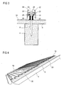
- FIG. 4 shows how in each support rail 20, a number of heat exchangers 10 are mounted, in this embodiment, eight heat exchanger 10. They form upwardly a flat surface on the later the solar modules 12 are placed. Each of a plurality of heat exchangers 10 form a flat surface, wherein a plurality of such planar surfaces are arranged one another over each other, as based on FIG. 4 can be seen in two such surfaces.
- the overlapping surfaces in this embodiment form a so-called hard roofing, so in addition to the weather resistance also offer a fire resistance against radiation and flying fire from the outside.
- the sheet thickness of the heat exchanger 10 on the surface side is at least 1 mm, in particular at least 1.5 mm.
- the design of the heat exchanger composite as a hard roofing has the advantage that the solar modules 12 do not necessarily have to make the requirement as hard roofing, so that the construction supervisory approval of the solar modules 12 is simplified.
- FIG. 5 A longitudinal section through the hybrid solar module roof mounting system 38 and thus also through the heat exchanger 10 and mounting rails 20 is in FIG. 5 shown. To see is the rafters 4 with the lower cover plate 6 thereon and a screwedgenjustierelement 8 with its sealing element 36. On the support head 18 is a support rail 20, the sake of clarity in FIG. 5 is shown only schematically. There are two support rails 20 can be seen, which are arranged one another over each other.
- the support rails 20 each have a plurality of upwardly open retaining recesses 40, in which the heat exchanger 10 are inserted with a support foot 42 from above.
- FIG. 6 shows this connection in more detail.
- the heat exchangers 10 are - as well as the support rails 20 - manufactured as aluminum extruded sections, so that they are - apart from holes and other openings and recesses at one or both ends - are designed uniform over its entire length.
- the support foot 42 engages with a retaining claw 46 in the retaining recess 40th one.
- Each retaining recess 40 has at its in FIG. 5 On the left side shown a contact surface for the support foot 42, which is tilted relative to the Dachsenkrechten in the direction of Geosenkrechte 44.
- the contact surface is tilted even beyond the perpendicular to the geosens 44 and has an angle of 40 ° to the dachsenkrechten or 50 ° to the longitudinal direction of the support rail 20. Due to the tilt of the heat exchanger 10 - when he pushes by its gravity in the direction of the eaves - pulled down on the roof or the support rail 20 so that it clamps play on the support rail 20.
- An upper support rail of the support foot 42 is located on top of the support rail 20 and thus limits retraction of the retaining claw 46 in the retaining recess 40th
- Adjacent heat exchangers 10 are interconnected via an engagement 48 lengthwise.
- the engagement 48 is in FIG. 6 shown in more detail and is designed as a deep tongue and groove joint, each heat exchanger 10 having a groove and a spring, and each spring engages in the groove of the other heat exchanger 10. In this way, the association of heat exchangers 10 is supported against each other.
- each heat exchanger 10 has only one support foot 42, which extends over the entire length of the heat exchanger 10.
- a single heat exchanger 10 is thus tiltable about a longitudinal axis lying in the support foot 42, which therefore runs parallel to the length of the heat exchanger 10.
- this tiltability is limited to a degree of vertical play of 1 mm in engagement 48.
- Verkippspiel a piece, so that the heat exchanger 10 easily tilted to each other.
- the heat exchanger 10 are slidably mounted in the support rails 20 by their suspension in the support rails 20 lengthwise. Furthermore, the heat exchangers 10 are mounted to each other displaceable over their entire length by their suspension in each other on the two-sided interventions 48. By these displacements and in particular by the Verkipples the heat exchanger 10 to each other mechanical stresses in the heat exchangers 10 by thermally different expansions or regionally different heating can be kept low. The surface of the heat exchanger 10 thus remains evenly even and a gap between heat exchangers 10 and the solar modules 12 remains low, so that a good heat transfer between the solar modules 12 and heat exchanger 10 is ensured.
- the solar modules 12 are placed on top of the heat exchanger 10 and protrude with a junction box 50 through an upper opening 76 of the heat exchanger 10, which in FIG. 6 is shown. At the bottom, the junction box 50 is closed by a lower cover 52, such as a cover plate, which can be inserted into two AusNFeschienen the corresponding heat exchanger 10. Each solar module 12 is screwed into threaded channels 54 of a heat exchanger 10. Each heat exchanger 10 has for this purpose a number of threaded channels 54 with a thread for receiving a retaining screw.
- the lowermost heat exchanger 10 is missing at the bottom an adjacent heat exchanger 10 for supporting against tilting and for stable storage.
- a support 56 is inserted lengthwise into an upper insertion compartment 58 (FIG. FIG. 3 ) of the bottom mounting rail 20 is inserted, on the bottom Heat exchanger 10 rests.
- Each of the lowermost mounting rails 20 may be provided with such a support 56.
- a holding member 62 is inserted for holding a gutter 64 from below in the longitudinal direction of the support rail 20.
- the insertion compartments 58, 60 may in this case be dimensioned such that the support 56 and / or the holding element 62 positively holds in the insertion compartment 58 or 60.
- Somewhat stronger is a screw connection or a positive connection, for example by a retaining bolt.
- Such a retaining bolt or a screw is represented by the retaining element 62.
- a screw can in this case be screwed into the mounting rail 20 and a retaining bolt inserted into the mounting rail 20, wherein a corresponding hole can be drilled in the mounting rail 20, for example, in the same way as the adjustment opening 28th
- each solar module 12 is held by a plurality of retaining clips 66, which are laterally inserted into a lower engagement 48 of the lowermost heat exchanger 10.
- Each retainer 66 engages behind its engagement 48 in a form-fitting manner, so that a withdrawal is blocked down by the rear handle.
- the retaining bracket 66 at the lower end of the second, third and each further upwardly arranged series of solar modules 12 is inserted below in the upper engagement 48 of the adjacent heat exchanger 10.
- an extension plate 68 is inserted as a sealing plate, which extends over the entire length of Heat exchanger 10 may extend.
- the extension plate 68 has over its entire length an extension in the direction of the ridge and at least 7 cm, in particular at least 12 cm. Characterized in that the headband 66 are only a few inches wide, a space between each other overlapping solar modules 12 is permeable to air, so that driving rain can be blown from below. By the extension plate 68, the blowing of driving rain down on the roof structure or the underlay 34 is avoided.
- the water collects on the extension plate 68 and flows down into a gutter 70, which in the embodiment shown is a part of the engagement 48, part of the ridge-side portion of the engagement 48 of the eaves-side heat exchanger 10 seen from the engagement 48.
- the gutter 70 is shaped so that it has a shape away from the overlying extension plate 68.
- the downward molding causes a distance 72 between two support lines 74 at which the extension plate 68 touches the gutter 70. By this distance 72, the capillary action between the two support lines 74 is broken, so that water from the eaves-side support line 74 can not reach the ridge-side support line 74.
- the distance 72 is at least 2 mm, in particular at least 4 mm.
- the gutter 70 is arranged so that at a roof pitch of ⁇ 10 °, the water flows from the extension plate 68 through the engagement 48 down on the eaves side down next heat exchanger 10 and then flows between heat exchanger 10 and solar module 12 down.
- Each heat exchanger 10 has one or more fluid channels 76 in the form of a water pipe.
- each heat exchanger 10 has two parallel to each other and in the longitudinal direction of the heat exchanger 10 extending water lines or fluid channels 76.
- the fluid channels 76 are formed integrally with the rest of the heat exchanger 10 and are connected to each other via a pipe connector 78 which in FIG. 7 is shown.
- FIG. 7 shows a view of the top of the mounted heat exchanger 10 and the pipe connector 78.
- the pipe connector 78 has for each fluid channel 76 a pipe socket 82 which is pressed into the corresponding fluid channel 76.
- the pipe connector 78 is connected to a plurality of heat exchangers 10 watertight.
- the screws 84 are respectively screwed into a screw channel 86 of the heat exchanger 10, so that a pressure-tight fluid line extending through a plurality of fluid channels 76 is formed by this or another fixed, positive connection.
- the pipe connector 78 may have such a length and number of pipe stubs 82 that all fluid channels 76 of all heat exchangers 10 of a plane, that is, of all heat exchangers 10 are connected to one another under a row of solar modules 12 lying next to one another.
- the pipe connector 78 may have a supply line and discharge, for example, to a water supply or discharge or to the next pipe connector 78 an overlapping or underschuppenden layer of heat exchangers 10th
Landscapes
- Engineering & Computer Science (AREA)
- Chemical & Material Sciences (AREA)
- Life Sciences & Earth Sciences (AREA)
- Sustainable Development (AREA)
- Sustainable Energy (AREA)
- Thermal Sciences (AREA)
- Physics & Mathematics (AREA)
- Combustion & Propulsion (AREA)
- Mechanical Engineering (AREA)
- General Engineering & Computer Science (AREA)
- Architecture (AREA)
- Civil Engineering (AREA)
- Structural Engineering (AREA)
- Roof Covering Using Slabs Or Stiff Sheets (AREA)
Description
Die Erfindung betrifft ein Hybridsolarmodul-Dachmontagesystem mit Höhenjustierelementen zur Befestigung auf einem Gebäudedach, Tragschienen zur Befestigung in Dachneigungsrichtung) des Gebäudedachs auf den Höhenjustierelementen, sodass sie auf den Höhenjustierelementen liegen, und Wärmetauscher mit einem Fluidkanal zur Befestigung in Firstrichtung auf den Tragschienen und mit einer planebenen Oberseite zur flächig anliegenden Anordnung von Solarmodulen darauf.The invention relates to a hybrid solar module roof mounting system with Höhenjustierelementen for mounting on a building roof, mounting rails for attachment in roof pitch direction) of the building roof on the Höhenjustierelementen so that they are on the Höhenjustierelementen, and heat exchangers with a fluid channel for attachment in Firstrichtung on the mounting rails and with a flat plane Top for the flat adjacent arrangement of solar modules on it.
Photovoltaikmodule, im Folgenden vereinfacht PV-Module genannt, dienen der Umwandlung von Sonneneinstrahlung in elektrische Energie. Bei einem solchen Umwandlungsprozess heizen sich die PV-Module auf, wodurch ihr Wirkungsgrad absinkt. Zur Lösung dieses Problems ist es bekannt, PV-Module zu kühlen, indem Kühlmittelleitungen an ihrer Rückseite entlang geführt werden, die von Kühlmittel durchströmt werden. Zur Übertragung von möglichst viel Wärme in das Kühlmittel ist die Kühlmittelleitung möglichst eng am Wärme erzeugenden Halbleitermaterial des PV-Moduls angeordnet. Beispielsweise ist sie von unten an das Halbleitermaterial anlaminiert.
Aus der
Eine einfache Befestigung von PV-Modulen mittels Haltebolzen an einem Dachsystem ist aus der
From the
A simple attachment of PV modules by means of retaining bolts on a roof system is from the
Es ist eine Aufgabe der vorliegenden Erfindung, ein Hybridsolarmodul-Dachmontagesystem anzugeben, mit dem gekühlte PV-Module einfach auf einem Gebäudedach montiert werden können.It is an object of the present invention to provide a hybrid solar module roof mounting system that can be used to easily mount cooled PV modules on a building roof.
Diese Aufgabe wird durch ein Hybridsolar-Dachmontagesystem der eingangs genannten Art gelöst, bei dem erfindungsgemäß die Tragschienen mehrere Montageausnehmungen aufweisen, durch die jeweils ein Höhenjustierelement hindurchgeführt ist, und über jeder Montageausnehmung ein Tragelement angeordnet ist, mit dem die Tragschiene auf dem Höhenjustierelement aufliegt und hierdurch vom Höhenjustierelement getragen ist.This object is achieved by a hybrid solar roof mounting system of the type mentioned, in which the support rails according to the invention have a plurality of mounting recesses, through each of which a Höhenjustierelement is passed, and each mounting recess a support member is arranged, with which the support rail rests on the height adjustment and thereby is carried by the height adjustment.
Die Erfindung geht von der. Überlegung aus, dass eine stoffschlüssige Befestigung von Kühlmittelleitungen oder allgemein einem Wärmetauscher an PV-Modulen zu mechanischen Spannungen und damit zu einer starken mechanischen Beanspruchung der PV-Module führen kann, die durch thermische Ausdehnungsbewegungen bei starken Temperaturschwankungen verursacht sind. Solche Spannungen können zu Ermüdungserscheinungen und im schlimmsten Fall zu einem Defekt des betreffenden PV-Moduls führen.The invention is based on. Considering that a cohesive attachment of coolant lines or in general a heat exchanger to PV modules can lead to mechanical stresses and thus to a strong mechanical stress of the PV modules, which are caused by thermal expansion movements at high temperature fluctuations. Such voltages can lead to fatigue and in the worst case to a defect of the relevant PV module.
Solche Spannungen lassen sich verringern, wenn das PV-Modul ohne stoffschlüssige Verbindung auf einem Wärmetauscher aufliegt, sodass sich beide Elemente bei starken Temperaturschwankungen relativ zueinander bewegen können. Eine solche Bewegungsfreiheit birgt jedoch den potentiellen Nachteil, dass sich zwischen dem PV-Modul und dem Wärmetauscher eine Luftschicht befindet, deren Dicke einen guten Wärmeübergang zwischen PV-Modul und Wärmetauscher stark verringert.Such voltages can be reduced if the PV module rests without a material connection on a heat exchanger, so that both elements can move relative to one another in the event of strong temperature fluctuations. However, such a freedom of movement has the potential disadvantage that there is an air layer between the PV module and the heat exchanger whose thickness greatly reduces a good heat transfer between the PV module and heat exchanger.
Dieser Nachteil kann verringert werden, wenn-die Wärmetauscher mit einer sehr ebenen Oberfläche auf dem Gebäudedach montiert werden, sodass die PV-Module flächig an den Wärmetauschern zu liegen kommen. Ein solcher exakt planebener Aufbau der Wärmetauscher auf beziehungsweise in einem Gebäudedach ist jedoch aufwändig.This disadvantage can be reduced if -the heat exchangers are mounted with a very even surface on the roof of the building, so that the PV modules come to lie flat against the heat exchangers. However, such a precisely planar structure of the heat exchanger on or in a building roof is complex.
Durch die Erfindung kann der Aufwand erheblich reduziert werden. Mithilfe der Höhenjustierelemente zwischen einer tragenden Struktur des Gebäudedachs und den Wärmetauschern kann vor der Befestigung der Tragschienen auf dem Gebäudedach ein sehr ebener Montageunterbau geschaffen werden, auf dem die Tragschienen und darauf die Wärmetauscher sehr exakt und einfach in einer Ebene ausgerichtet montierbar sind. Entsprechend eben ist auch die plane Oberseite der Wärmetauscher, auf die die Solarmodule beziehungsweise PV-Module aufgelegt werden können. Es kann ein guter Wärmeübertrag bei Aufrechterhaltung der Relativbewegung der Elemente zueinander erhalten bleiben.By the invention, the effort can be significantly reduced. Using the Höhenjustierelemente between a supporting structure of the building roof and the heat exchangers, a very flat mounting base can be created before mounting the mounting rails on the building roof on which the support rails and the heat exchanger are very precisely and easily aligned aligned in one plane. Correspondingly even is the flat top of the heat exchanger to which the solar modules or PV modules can be placed. It can maintain a good heat transfer while maintaining the relative movement of the elements to each other.
Durch das erfindungsgemäße System kann eine Fläche von mehreren Photovoltaik-Modulen in einer besonders einfachen Weise zur solarthermischen Energiegewinnung genutzt werden. Aus einem Solarmodulsystem entsteht hierdurch ein Hybridsolarmodulsystem, unabhängig davon, ob die abgeführte Wärmeenergie später genutzt wird. Bedeutend ist auch die Kühlung der Solarmodule, deren Temperaturniveau durch die Wärmetauscher zweckmäßigerweise auf maximal 50°C eingestellt wird, damit die PV-Module effektiv gekühlt werden. Wenn gewünscht, kann die von den PV-Modulen abgegebene Wärme weiteren Betriebsprozessen zur Verfügung gestellt werden. So kann die Wärme zur Anhebung eines Heizungs-Rücklaufs verwendet werden. Ebenfalls möglich ist die Verwendung der Wärme in einer Niedertemperaturheizung, beispielsweise in einer Bodenheizung und/oder einer Wandheizung. Ebenfalls vorteilhaft ist die Vorheizung einer Sole-Wasser-Wärmepumpe.The system according to the invention makes it possible to use an area of a plurality of photovoltaic modules in a particularly simple manner for solar thermal energy production. From a solar module system, this creates a hybrid solar module system, regardless of whether the dissipated heat energy is used later. Significant is the cooling of the solar modules, the temperature level is set by the heat exchanger expediently to a maximum of 50 ° C, so that the PV modules are effectively cooled. If desired, the heat given off by the PV modules can be made available to further operating processes. Thus, the heat can be used to increase a heating return. Also possible is the use of heat in a low-temperature heating, for example in a floor heating and / or wall heating. Also advantageous is the preheating a brine-water heat pump.
Das Hybridsolarmodul-Dachmontagesystem dient zweckmäßigerweise der Befestigung von auf einem Schrägdach angeordneten und als Dacheindeckung dienenden Solarmodulen. Die Solarmodule können bei einem solchen sogenannten Indach-System PhotovoltaikModule, also PV-Module sein. Die Erfindung ist jedoch auch geeignet zur Verwendung mit reinen Solarthermie-Modulen, die zum Umwandeln von Sonneneinstrahlung in Wärme vorgesehen sind. Auf die Hybridnutzung wird dann verzichtet.The hybrid solar module roof mounting system is expediently used for fastening arranged on a pitched roof and serving as a roof covering solar modules. The solar modules can be in such a so-called in-roof system photovoltaic modules, so PV modules. However, the invention is also suitable for use with pure solar thermal modules designed to convert solar radiation into heat. The hybrid use is then waived.
Die Tragschienen sind zweckmäßigerweise jeweils ein Metallprofil, beispielsweise ein Stranggussprofil, insbesondere aus Aluminium. Sie tragen die Solarmodule und die Wärmetauscher und sind ihrerseits über die Höhenjustierelemente an einer Gebäudedachkonstruktion befestigt, beispielsweise an einer Dachsparrenkonstruktion. Im montierten Zustand verlaufen die Tragschienen zweckmäßigerweise in Dachneigungsrichtung, also in einer Ablaufrichtung eines Schrägdachs vom First zur Traufe.The mounting rails are expediently each a metal profile, for example a continuous casting profile, in particular of aluminum. They carry the solar modules and the heat exchanger and are in turn attached via the Höhenjustierelemente to a building roof structure, such as a rafter construction. In the assembled state, the support rails expediently run in the roof pitch direction, ie in a flow direction of a pitched roof from the ridge to the eaves.
Das Gebäudedach ist zweckmäßigerweise ein Satteldach und kann ein Dach eines jedweden Gebäudes sein, auch einer Scheune, eines Stalls, einer Halle, eines Unterstands oder dergleichen. Das Gebäudedach umfasst zweckmäßigerweise eine Dachkonstruktion in Form einer Holzkonstruktion, wobei auch Konstruktionen aus Holz und anderen Materialien oder nur aus Metall möglich sind.The building roof is expediently a pitched roof and may be a roof of any building, including a barn, a stable, a hall, a shelter or the like. The building roof expediently comprises a roof structure in the form of a wooden construction, whereby constructions of wood and other materials or only of metal are possible.
Die Höhenjustierelemente sind Elemente, die in die Dachkonstruktion eingebracht werden können bzw. darin eingebracht sind und auf denen die Tragschienen und damit auch die Solarmodule ruhen, die also deren Gewicht tragen. Die Höhenjustierelemente sind zweckmäßigerweise so bemessen, dass die Tragschienen zumindest überwiegend von der darunter liegenden Dachkonstruktion beabstandet sind, sie also zumindest überwiegend, insbesondere vollständig auf den Höhenjustierelementen ruhen. Die Höhenjustierelemente können in die Dachkonstruktion eingeschraubt sein, weisen also ein unteres Schraubgewinde auf und sind in einer einfachsten Variante Schrauben. Die Höhenjustierelemente haben vorteilhafterweise einen verbreiterten Kopf, auf dem das Gewicht der Tragschiene und des Solarmoduls ruht. Der Kopf kann ein Schraubenkopf sein, der zum Tragen des gesamten Dachmontagesystems und der Solarmodule ausgelegt ist. Das System mit den Modulen kann auf den Tragköpfen der Höhenjustierelemente aufliegen.The Höhenjustierelemente are elements that can be introduced into the roof structure or are introduced therein and on which the mounting rails and thus the solar modules rest, so the weight of which carry. The height adjustment elements are expediently dimensioned so that the mounting rails are at least predominantly spaced from the underlying roof structure, so they rest at least predominantly, in particular completely on the Höhenjustierelementen. The Höhenjustierelemente can be screwed into the roof construction, so have a lower screw on and are in a simplest variant screws. The Höhenjustierelemente advantageously have a widened head on which rests the weight of the support rail and the solar module. The head may be a screw head designed to support the entire roof mounting system and the solar modules. The system with the modules can rest on the support heads of the height adjustment elements.
Die Wärmetauscher beinhalten einen Fluidkanal, also eine oder mehrere Leitungen zum Führen von Wasser mit oder ohne Zusätzen oder einer anderen Flüssigkeit. Der Fluidkanal ist zweckmäßigerweise eine Druckwasserführung, in der ein Überdruck aufgebaut werden kann, sodass beispielsweise Wasserdruck in den Wasserleitungen aufrechterhalten bleibt. Der Fluidkanal ist vorteilhafterweise in den Wärmetauschern integriert, also einstückig mit einem Wärmetauscher ausgeführt. Ein Wärmetauscher ist zweckmäßigerweise ein Metallprofil, beispielsweise ein Stranggussprofil, insbesondere aus Aluminium. Ein Wärmetauscher weist auf seiner Oberseite eine ebene Fläche auf, auf die ein Solarmodul, insbesondere ein PV-Modul, vollflächig aufgelegt werden kann, sodass ein vollflächiger Kontakt zwischen der Oberseite und dem Modul entsteht. In der Oberseite kann eine Öffnung zur Aufnahme einer Anschlussdose eines Moduls vorhanden sein.The heat exchangers include a fluid channel, that is, one or more conduits for carrying water with or without additives or other liquid. The fluid channel is expediently a pressurized water guide, in which an overpressure can be built up, so that, for example, water pressure in the water lines is maintained. The fluid channel is advantageously integrated in the heat exchangers, that is designed in one piece with a heat exchanger. A heat exchanger is expediently a metal profile, for example a continuous casting profile, in particular of aluminum. A heat exchanger has on its upper side a flat surface onto which a solar module, in particular a PV module, can be placed over the entire surface, so that full-surface contact is created between the upper side and the module. In the top there may be an opening for receiving a junction box of a module.
Erfindungsweise weisen die Tragschienen mehrere längliche Montageausnehmungen mit jeweils einem Breitbereich und einem Schmalbereich auf. Die Höhenjustierelemente weisen zweckmäßigerweise einen Tragkopf auf, der durch den Breitbereich hindurch passt, nicht jedoch durch den Schmalbereich. Hierdurch kann der Tragkopf durch den Breitbereich hindurchgeführt werden und hinter dem Schmalbereich verriegeln, sodass ein Abheben der Tragschienen nach oben blockiert wird. Auf diese Weise ist eine einfache Montage der Tragschienen auf den Höhenjustierelementen möglich, indem eine Tragschiene von oben auf zwei oder mehr Höhenjustierelemente aufgesetzt wird, sodass die Tragköpfe der Höhenjustierelemente durch den Breitbereich hindurchgeführt werden. Anschließend kann die Tragschiene so zu den Höhenjustierelementen verschoben werden, dass diese durch den Schmalbereich ragen und der Tragkopf hinter dem Schmalbereich verriegelt.According to the invention, the mounting rails have a plurality of elongated mounting recesses each having a wide area and a narrow area. The height adjustment elements Expediently have a support head, which fits through the wide area, but not through the narrow area. In this way, the support head can be passed through the wide area and lock behind the narrow area, so that a lifting of the support rails is blocked upwards. In this way, a simple mounting of the support rails on the Höhenjustierelementen is possible by a support rail is placed from above on two or more Höhenjustierelemente, so that the support heads of Höhenjustierelemente be passed through the wide area. Subsequently, the support rail can be moved to the Höhenjustierelementen that they protrude through the narrow area and the support head locked behind the narrow area.
Weiter weisen die Tragschienen mehrere Montageausnehmungen zum Hindurchführen von jeweils einem Höhenjustierelement auf und über jeder Montageausnehmung ein Tragelement, insbesondere ein Tragsteg, zur Auflage auf dem Höhenjustierelement und zum Tragen der Tragschiene. Das Tragelement kann eine durchgehende Struktur sein, insbesondere bei der Ausführung der Tragschiene als Stranggussprofil, sodass dann ein Tragelement über mehrere Montageausnehmungen ragt zum Tragen der Tragschiene. Eine Tragschiene kann auf die Höhenjustierelemente aufgesteckt und mit dem oder den Tragelementen auf die Höhenjustierelemente aufgelegt werden.Furthermore, the mounting rails have a plurality of mounting recesses for passing in each case one height adjustment element and above each mounting recess a support element, in particular a support web, for resting on the height adjustment element and for supporting the mounting rail. The support member may be a continuous structure, in particular in the execution of the support rail as a continuous casting, so then a support member projects over a plurality of mounting recesses for supporting the support rail. A mounting rail can be plugged onto the Höhenjustierelemente and placed with the or the support elements on the Höhenjustierelemente.
Nach der Montage der Tragschienen auf den Höhenjustierelementen kann es sein, dass die Höhenjustierelemente nachjustiert werden sollten, um Unebenheiten in der Auflagefläche zur Auflage für die Solarmodule auszugleichen. Ein solches Nachjustieren kann erleichtert werden, wenn das Tragelement über der Montageausnehmung eine Justieröffnung zum Hindurchführen eines Werkzeugs aufweist, die kleiner als ein Tragkopf des Höhenjustierelements ist. Das Werkzeug kann durch das Tragelement hindurchgeführt werden, das durch die geringe Ausdehnung der Justieröffnung seine tragende Funktion auf dem Höhenjustierelement nicht verliert.After mounting the mounting rails on the Höhenjustierelementen it may be that the Höhenjustierelemente should be readjusted to compensate for unevenness in the support surface for support for the solar modules. Such a readjustment can be facilitated if the support element has an adjustment opening above the mounting recess for passing a tool which is smaller than a support head of the height adjustment element. The tool can be passed through the support element, which does not lose its supporting function on the height adjustment by the small extent of the adjustment.
Weiter ist es vorteilhaft, wenn die Tragschienen oberhalb einer Montageausnehmung und insbesondere oberhalb einer Justieröffnung jeweils ein oder mehrere Einschubfächer zum Einschieben eines Flacheisens in Längsrichtung des Tragelements und insbesondere zum kraftschlüssigen Halten des Flacheisens aufweist. Das Flacheisen kann ein Metallprofil sein, beispielsweise aus Eisen oder Aluminium, und kann beispielsweise ein Flacheisen zum Halten einer Regenrinne sein. Ebenfalls möglich ist ein Kunststoffprofil. Besonders vorteilhaft sind zwei übereinanderliegende Einschubfächer für je ein Flacheisen, sodass, insbesondere in das obere Einschubfach, ein Stützelement für einen untersten Wärmetauscher eingeführt und dort gehalten werden kann.Further, it is advantageous if the mounting rails above a mounting recess and in particular above an adjustment opening in each case one or more insertion compartments for insertion of a flat iron in the longitudinal direction of the support member and in particular for non-positive retention of the flat iron. The flat iron may be a metal profile, for example of iron or aluminum, and may for example be a flat iron for holding a gutter. Also possible is a plastic profile. Particularly advantageous are two superimposed insert compartments for each flat iron, so that, in particular in the upper insertion compartment, a support element for a lowermost heat exchanger can be introduced and held there.
Das Hybridsolarmodul-Dachmontagesystem kann auf einem Gebäudedach angeordnet sein, wobei die Höhenjustierelemente unmittelbar oder mittelbar an einer tragenden Dachkonstruktion, insbesondere an einer Holzkonstruktion des Gebäudedachs befestigt sind, beispielsweise in die Holzkonstruktion eingeschraubt sind. Die Dachkonstruktion kann hierbei als Teil des Dachmontagesystems angesehen werden.The hybrid solar module roof mounting system can be arranged on a building roof, wherein the height adjustment elements are directly or indirectly attached to a supporting roof construction, in particular to a wooden structure of the building roof, for example screwed into the wooden structure. The roof construction can be considered as part of the roof mounting system.
Vorteilhafterweise umfassen die Höhenjustierelemente jeweils einen oberen Tragkopf, wobei mehrere in Firstrichtung verlaufende Reihen von Tragköpfen gemeinsam eine Ebene aufspannen, in der mehrere Tragschienen befestigt werden. Zweckmäßigerweise spannen Gruppen von jeweils mehreren in Firstrichtung verlaufenden Reihen von Tragköpfen mehrere Ebenen auf, die in Dachneigungsrichtung überschuppend angeordnet sind. Auf diese Weise kann ein überschuppender Verband von Wärmetauschern und darauf ein überschuppender Verband von Solarmodulen montiert werden.Advantageously, the Höhenjustierelemente each comprise an upper support head, wherein a plurality of extending in the firing direction rows of support heads together span a plane in which a plurality of mounting rails are attached. Conveniently, groups of a plurality of rows of support heads extending in the firing direction span a plurality of levels that are arranged in an overhanging manner in the direction of the roof pitch. In this way, an overlapping bandage of heat exchangers and thereupon an overlapping bandage of solar modules can be mounted.
Bei einer Befestigung der Höhenjustierelemente in einer Dachkonstruktion ist es vorteilhaft, wenn die betreffende Verbindungsstelle trocken gehalten wird. Dies kann in einfacher Weise erreicht werden, wenn die Höhenjustierelemente zwischen der Dachkonstruktion und der Tragschiene jeweils von einem Abdichtelement umgeben sind, das das Höhenjustierelement nach außen hin abdichtet. Ein solches Abdichtelement kann ein Gummizylinder sein, der zweckmäßigerweise zwischen einer Unterdeckbahn der Dachkonstruktion und Tragschiene eingeklemmt ist und insbesondere durch das Einklemmen abdichtet.When attaching the Höhenjustierelemente in a roof construction, it is advantageous if the junction in question is kept dry. This can be achieved in a simple manner if the height adjustment elements between the roof construction and the mounting rail are each surrounded by a sealing element which seals the height adjustment element to the outside. Such a sealing element may be a blanket cylinder, which is expediently clamped between a bottom cover web of the roof construction and mounting rail and in particular seals by pinching.
Die Wärmetauscher sind zweckmäßigerweise an den Tragschienen befestigt, insbesondere oben an den Tragschienen befestigt. Hierfür ist es vorteilhaft, wenn die Tragschienen jeweils mehrere nach oben offene Halteausnehmungen aufweisen, in die die Wärmetauscher mit einem Tragfuß von oben eingefügt sind. Ein Tragfuß eines Wärmetauschers ragt somit zumindest teilweise in die Halteausnehmung ein, sodass Wärmetauscher und Tragschiene einen Formschluss bilden.The heat exchangers are expediently fastened to the carrier rails, in particular fastened to the carrier rails at the top. For this purpose, it is advantageous if the mounting rails each have a plurality of upwardly open retaining recesses into which the Heat exchangers are inserted with a support foot from above. A support foot of a heat exchanger thus protrudes at least partially into the retaining recess, so that the heat exchanger and the support rail form a positive connection.
Um ein unerwünschtes Lösen eines Wärmetauschers von einer Tragschiene entgegenzuwirken sind die Halteausnehmungen - zumindest in einer Anlagefläche für einen Tragfuß eines Wärmetauschers - relativ zur Dachsenkrechten in Richtung zur Geosenkrechten - und insbesondere über die Geosenkrechte hinaus verkippt. Der Tragfuß wird hierdurch vom Gewicht des Wärmetauschers in die Halteausnehmung gedrückt und ein Abheben nach oben wird verhindert.In order to counteract undesired loosening of a heat exchanger from a mounting rail, the retaining recesses are tilted - at least in a contact surface for a support foot of a heat exchanger - relative to the dachsenkrechte in the direction of the geosenkrechte - and in particular beyond the Geosenkrechte addition. The support foot is thereby pressed by the weight of the heat exchanger in the retaining recess and lifting up is prevented.
Weiter ist es vorteilhaft, wenn die Wärmetauscher jeweils zumindest einen Tragfuß zum Einstecken in eine Halteausnehmung der Tragschiene von oben aufweisen, der eine Auflagefläche zum Auflegen auf die Tragschiene und eine Haltekralle zum Eingreifen in die Halteausnehmung aufweist. Hierdurch kann in sehr einfacher Weise ein ausreichend fester Formschluss erreicht werden, der dennoch eine Beweglichkeit beim Auftreten von mechanischen Spannungen wegen Temperaturänderungen aufrechterhält.Further, it is advantageous if the heat exchanger each have at least one support foot for insertion into a holding recess of the support rail from above, which has a support surface for placement on the support rail and a retaining claw for engaging in the retaining recess. In this way, in a very simple manner, a sufficiently strong positive connection can be achieved, which nevertheless maintains a mobility when mechanical stresses occur due to temperature changes.
Bei starken Temperaturschwankungen kann es zu unterschiedlichen Ausdehnungsverhalten von Elementen des Dachmontagesystems kommen. Um Spannungen in den Wärmetauschern zu vermeiden, die zu Abweichungen ihrer planebenen Oberfläche führen können, ist es vorteilhaft, wenn die Wärmetauscher beweglich an den Tragschienen befestigt sind. Insbesondere vorteilhaft ist eine Verschiebbarkeit der Wärmetauscher in Firstrichtung relativ zu den Tragschienen in fertig montiertem Zustand.With strong temperature fluctuations, different expansion characteristics of elements of the roof mounting system can occur. In order to avoid stresses in the heat exchangers, which can lead to deviations of their flat surface, it is advantageous if the heat exchangers are movably attached to the support rails. Particularly advantageous is a displaceability of the heat exchanger in the firing direction relative to the mounting rails in the fully assembled state.
Mit gleichem Vorteil sind die Wärmetauscher zweckmäßigerweise so an den Tragschienen befestigt, dass sie einzeln um ihre Längsachse verkippbar sind. Auch auf diese Weise kann thermischen Spannungen entgegengewirkt werden. Die Wärmetauscher umfassen hierfür zweckmäßigerweise einen Tragfuß in Form eines Schienenelements, mit dem sie in mehreren Tragschienen stehen, wobei ein einzelner fertig an den Tragschienen befestigter Wärmetauscher umfallen würde, also im Tragfuß nicht genügend Halt für einen freien Stand hat.With the same advantage, the heat exchangers are expediently fastened to the mounting rails such that they can be tilted individually about their longitudinal axis. In this way, thermal stresses can be counteracted. For this purpose, the heat exchangers expediently comprise a support foot in the form of a rail element, with which they stand in a plurality of mounting rails, with a single finished heat exchanger mounted on the mounting rails falling over, ie not having sufficient support for a free stand in the support foot.
Zur Stützung von beweglichen Wärmetauschern ist es vorteilhaft, wenn zwei benachbarte Wärmetauscher in der Weise formschlüssig miteinander verbunden sind, dass sie trotz einer verkippbaren Befestigung in den Tragschienen einen selbst stabilisierenden Verbund bilden. Ein einzelner Wärmetauscher würde zwar gegebenenfalls aus seiner Betriebsposition verkippen, der Verbund verhindert jedoch ein solches Verkippen, sodass die planebene Oberfläche aufrechterhalten wird.To support mobile heat exchangers, it is advantageous if two adjacent heat exchangers are positively connected to one another in such a way that they form a self-stabilizing composite despite a tiltable attachment in the support rails. Although a single heat exchanger would tilt from its operating position, if necessary, the composite prevents such tilting, so that the flat surface is maintained.
Eine weitere Möglichkeit zum Entgegenwirken von mechanischen Spannungen hervorgerufen durch Temperaturänderungen besteht darin, dass die Wärmetauscher zueinander in Längsrichtung beweglich sind, und zwar auch in fertig montiertem Zustand des Dachmontagesystems - gegebenenfalls ohne montierte Solarmodule. Die Wärmetauscher können zwar ineinander formschlüssig eingreifen, der Formschluss erlaubt jedoch eine Verschiebbarkeit in Längsrichtung, zweckmäßigerweise über eine Länge von zumindest 3 cm, insbesondere über die gesamte Länge der Wärmetauscher.Another possibility for counteracting mechanical stresses caused by temperature changes is that the heat exchangers are mutually movable in the longitudinal direction, even in the fully assembled state of the roof mounting system - possibly without mounted solar modules. Although the heat exchangers can engage in one another in a form-fitting manner, the positive locking allows displaceability in the longitudinal direction, expediently over a length of at least 3 cm, in particular over the entire length of the heat exchangers.
Mit gleichem Vorteil besteht in der Verbindung zwischen benachbarten Wärmetauschern ein Verkippspiel von zumindest 0,5 mm, insbesondere von zumindest 1 mm, sodass durch das Verkippspiel eine Verkippbarkeit der Wärmetauscher in den Tragschienen im Rahmen des Spiels erhalten bleibt. Die Wärmetauscher können auf diese Weise auch bei thermischen Schwankungen eine planebene gemeinsame Oberfläche bilden und bleiben zueinander leicht beweglich.With the same advantage in the connection between adjacent heat exchangers Verkippspiel of at least 0.5 mm, in particular of at least 1 mm, so that by Verkippspiel a Verkippbarkeit the heat exchanger in the mounting rails is retained during the game. In this way, the heat exchangers can form a plane-like common surface even in the case of thermal fluctuations and remain easily movable relative to one another.
Die Erfindung ist außerdem gereichtet auf ein Verfahren zum Montieren eines Hybridsolarmodulsystems. Es wird vorgeschlagen, dass auf einer Dachoberfläche erfindungsgemäß Höhenjustierelemente gesetzt werden, diese in der Höhe so zueinander justiert werden, dass sie in einer gewünschten, insbesondere ebenen Fläche liegen, Tragschienen an den Höhenjustierelementen befestigt werden und darauf Wärmetauscher mit einem insbesondere integrierten Fluidkanal montiert werden. Auf die Oberseite der Wärmetauscher können nun Solarmodule flächig aufgelegt werden.The invention is also directed to a method of assembling a hybrid solar module system. It is proposed that Höhenjustierelemente be set according to the invention on a roof surface, they are adjusted in height to each other so that they lie in a desired, especially flat surface, mounting rails are attached to the Höhenjustierelementen and heat exchangers are mounted with a particular integrated fluid channel. On the top of the heat exchanger solar panels can now be placed flat.
Die oben beschriebenen Eigenschaften, Merkmale und Vorteile dieser Erfindung, wie in den Ansprüchen definiert, sowie die Art und Weise, wie diese erreicht werden, werden klarer und deutlicher verständlich im Zusammenhang mit der folgenden Beschreibung der Ausführungsbeispiele, die im Zusammenhang mit den Zeichnungen näher erläutert werden. Die Ausführungsbeispiele dienen der Erläuterung der Erfindung und beschränken die Erfindung nicht auf die darin angegebene Kombination von Merkmalen, auch nicht in Bezug auf funktionale Merkmale.The above-described characteristics, features and advantages of this invention as defined in the claims, as well as the manner in which they are achieved, will become clearer and more clearly understood in connection with the following description of the embodiments which will be described in detail in conjunction with the drawings become. The embodiments serve to illustrate the invention and do not limit the invention to the combination of features specified therein, not even with respect to functional features.
Es zeigen:
- FIG 1
- einen Ausschnitt eines Gebäudedachs mit darauf befestigten Höhenjustierelementen,
- FIG 2
- den Ausschnitt des Gebäudedachs aus
FIG 1 mit auf den Höhenjustierelementen aufgesetzten Tragschienen, - FIG 3
- eine der Tragschienen auf einem der Höhenjustierelemente in einem Querschnitt,
- FIG 4
- den Ausschnitt des Gebäudedachs mit auf den Tragschienen aufgesetzten Wärmetauschern,
- FIG 5
- einen Längsschnitt durch ein Hybridsolarmodul-Dachmontagesystem mit Wärmetauschern auf Tragschienen und Höhenjustierelementen,
- FIG 6
- einen vergrößerten Ausschnitt aus
FIG 5 und - FIG 7
- eine Draufsicht auf montierte Wärmetauscher mit einer Rohrverbindereinheit zum Verbinden von Fluidkanälen in den Wärmetauschern.
- FIG. 1
- a section of a building roof with Höhenjustierelementen mounted thereon,
- FIG. 2
- the section of the building roof
FIG. 1 with mounting rails attached to the height adjustment elements, - FIG. 3
- one of the mounting rails on one of the height adjustment elements in a cross section,
- FIG. 4
- the section of the building roof with heat exchangers placed on the mounting rails,
- FIG. 5
- a longitudinal section through a hybrid solar module roof mounting system with heat exchangers on mounting rails and Höhenjustierelementen,
- FIG. 6
- an enlarged section
FIG. 5 and - FIG. 7
- a plan view of mounted heat exchanger with a tube connector unit for connecting fluid channels in the heat exchangers.
Um eine gute Verbindung zwischen den in
Der Abstand in Firstrichtung 14 der Höhenjustierelemente 8 zueinander kann hierbei der Breite der später aufzulegenden Solarmodule 12 entsprechen. Der Abstand der Höhenjustierelemente 8 zueinander in Dachneigungsrichtung 16 beziehungsweise Ablaufrichtung des Gebäudedachs 2 kann die Hälfte der Länge eines aufzulegenden Solarmoduls 12 sein, wobei der Abstand auch unterschiedlich sein kann, und der Abstand von einem Höhenjustierelement 8 zu seinem übernächsten Nachbarn der Länge des Solarmoduls 12 - abzüglich Überschuppungslänge - sein kann.The distance in the firing
Zum Erreichen der planebenen Oberfläche werden die Höhenjustierelemente 8 nun auf ihre Position zueinander vermessen. Beispielsweise werden die Tragköpfe 18 der Höhenjustierelemente 8 auf ihre Anordnung derart durch Vermessung geprüft, ob die Tragköpfe 18 von zwei in Firstrichtung 14 verlaufenden Höhenjustierelementreihen eine Ebene bilden. Dies kann durch einen Laserstrahl oder eine Schnur, wie in
Anschließend werden Tragschienen 20, wie in
Hierfür umfassen die Tragschienen 20 jeweils zwei Montageausnehmungen 22 mit jeweils einem Breitbereich 24 und einem Schmalbereich 26, wie in der abschnittsweisen Draufsicht auf eine Tragschiene 20 in
Über dem Tragkopf 18 ist in der Draufsicht aus
Das Höhenjustierelement 8 ist durch eine Unterdeckbahn 34 in die Unterdeckplatte 6 beziehungsweise den Dachsparren 4 eingeschraubt. Um eine gute Dichtigkeit der Unterdeckbahn 34 aufrechtzuerhalten, ist ein Abdichtelement 36 zwischen Holzkonstruktion und Tragschiene 20 um das Höhenjustierelement 8 gelegt. Das Abdichtelement 36 ist ein Gummi-Hohlzylinder, der zwischen Tragschiene 20 und Holzkonstruktion, in diesem Fall der Unterdeckplatte 6 bzw. der Unterdeckbahn 34, eingeklemmt ist und hierdurch das Loch in der Unterdeckbahn 34 ringsherum abdichtet.The
Diese überschuppenden Oberflächen bilden von sich aus bereits eine wetterfeste Außenbedachung, die als Außendach bereits vollständig geschlossen ist und das Dach vollständig schützt. Die später auf den Oberflächen montierten Solarmodule 12 sind für die Wetterfestigkeit daher nicht notwendig.These overlapping surfaces already form a weatherproof outer roofing, as an outer roof already is completely closed and completely protects the roof. The later mounted on the surfaces of
Außerdem bilden die überschuppenden Oberflächen in diesem Ausführungsbeispiel eine sogenannte harte Bedachung, die also neben der Wetterfestigkeit auch eine Feuerfestigkeit gegen Strahlung und Flugfeuer von außen bieten. Hierfür beträgt die Blechdicke der Wärmetauscher 10 oberflächenseitig zumindest 1 mm, insbesondere zumindest 1,5 mm. Die Ausführung des Wärmetauscherverbunds als harte Bedachung hat den Vorteil, dass die Solarmodule 12 die Anforderung als harte Bedachung nicht zwingend leisten müssen, so dass die bauaufsichtliche Zulassung der Solarmodule 12 vereinfacht wird.In addition, the overlapping surfaces in this embodiment form a so-called hard roofing, so in addition to the weather resistance also offer a fire resistance against radiation and flying fire from the outside. For this purpose, the sheet thickness of the
Ein Längsschnitt durch das Hybridsolarmodul-Dachmontagesystem 38 und damit auch durch die Wärmetauscher 10 und Tragschienen 20 ist in
Die Tragschienen 20 weisen jeweils mehrere nach oben hin offene Halteausnehmungen 40 auf, in die die Wärmetauscher 10 mit einem Tragfuß 42 von oben eingefügt sind.
Einander benachbarte Wärmetauscher 10 sind über einen Eingriff 48 der Länge nach miteinander verbunden. Der Eingriff 48 ist in
Wie aus
Außerdem sind die Wärmetauscher 10 durch ihre Einhängung in den Tragschienen 20 der Länge nach in den Tragschienen 20 verschiebbar gelagert. Des Weiteren sind die Wärmetauscher 10 durch ihre Einhängung ineinander an den beidseitigen Eingriffen 48 über ihre gesamte Länge zueinander verschiebbar gelagert. Durch diese Verschiebbarkeiten und insbesondere auch durch die Verkippbarkeit der Wärmetauscher 10 zueinander können mechanische Spannungen in den Wärmetauschern 10 durch thermisch unterschiedliche Ausdehnungen beziehungsweise regional verschiedene Erwärmungen gering gehalten werden. Die Oberfläche der Wärmetauscher 10 bleibt hierdurch sehr gleichmäßig planeben und ein Spalt zwischen Wärmetauschern 10 und den Solarmodulen 12 bleibt gering, sodass ein guter Wärmeübergang zwischen Solarmodulen 12 und Wärmetauscher 10 gewährleistet ist.In addition, the
Die Solarmodule 12 sind von oben auf die Wärmetauscher 10 aufgelegt und ragen mit einer Anschlussdose 50 durch eine obere Öffnung 76 eines der Wärmetauscher 10, die in
Dem untersten Wärmetauscher 10 fehlt nach unten hin ein benachbarter Wärmetauscher 10 zum Abstützen gegen ein Verkippen und für eine stabile Lagerung. Zum Ausgleich ist eine Stütze 56 der Länge nach in ein oberes Einschubfach 58 (
In ein darunterliegendes Einschubfach 60 ist ein Halteelement 62 zum Halten einer Regenrinne 64 von unten in Längsrichtung der Tragschiene 20 eingesteckt. Die Einschubfächer 58, 60 können hierbei so bemessen sein, dass die Stütze 56 und/oder das Halteelement 62 kraftschlüssig im Einschubfach 58 bzw. 60 festhält. Etwas fester ist eine Verschraubung oder eine formschlüssige Verbindung, z.B. durch einen Haltebolzen. In
Nach unten hin wird jedes Solarmodul 12 durch mehrere Haltebügel 66 gehalten, die in einen unteren Eingriff 48 des untersten Wärmetauschers 10 seitlich eingeschoben sind. Jeder Haltebügel 66 hintergreift hierbei seinen Eingriff 48 formschlüssig, sodass ein Abziehen nach unten durch den Hintergriff blockiert ist.Towards the bottom, each
Der Haltebügel 66 am unteren Ende der zweiten, dritten und jeder weiteren nach oben angeordneten Reihe von Solarmodulen 12 ist unten in den oberen Eingriff 48 des benachbarten Wärmetauschers 10 eingesteckt. Durch den Haltebügel 66 sind somit einander in der Überschuppung benachbarter Wärmetauscher 10 miteinander verbunden.The retaining
In den oberseitigen Eingriff der nach oben zur Überschuppung hin letzten Tragschiene 20 ist ein Verlängerungsblech 68 als Dichtungsblech eingeführt, die sich über die gesamte Länge des Wärmetauschers 10 erstrecken kann. Das Verlängerungsblech 68 weist über seine gesamte Länge eine Ausdehnung in Richtung zum First und zumindest 7 cm, insbesondere zumindest 12 cm auf. Dadurch, dass die Haltebügel 66 nur einige Zentimeter breit sind, ist ein Zwischenraum zwischen einander überschuppenden Solarmodulen 12 luftdurchlässig, sodass Schlagregen von unten eingeblasen werden kann. Durch das Verlängerungsblech 68 wird das Einblasen von Schlagregen nach unten auf die Dachkonstruktion beziehungsweise die Unterdeckbahn 34 vermieden.In the top-side engagement of the last up to the overlap
Das Wasser sammelt sich auf dem Verlängerungsblech 68 und fließt nach unten in eine Auffangrinne 70, die im gezeigten Ausführungsbeispiel ein Teil des Eingriffs 48 ist, und zwar Teil des firstseitigen Teils des Eingriffs 48 des vom Eingriff 48 gesehen traufseitigen Wärmetauschers 10. Die Auffangrinne 70 ist so geformt, dass sie eine Ausformung weg vom darüber liegenden Verlängerungsblech 68 aufweist. Die Ausformung nach unten bewirkt einen Abstand 72 zwischen zwei Auflagelinien 74, an denen das Verlängerungsblech 68 die Auffangrinne 70 berührt. Durch diesen Abstand 72 wird die Kapillarwirkung zwischen den beiden Auflagelinien 74 gebrochen, so dass Wasser von der traufseitigen Auflagelinie 74 nicht zur firstseitigen Auflagelinie 74 gelangen kann. Der Abstand 72 beträgt zumindest 2 mm, insbesondere zumindest 4 mm.The water collects on the
Die Auffangrinne 70 ist so angeordnet, dass bei einer Dachneigung von ≥ 10° das Wasser von dem Verlängerungsblech 68 durch den Eingriff 48 nach unten auf den traufseitig nach unten nächsten Wärmetauscher 10 fließt und dann zwischen Wärmetauscher 10 und Solarmodul 12 nach unten abfließt.The
Jeder Wärmetauscher 10 weist einen oder mehrere Fluidkanäle 76 in Form einer Wasserleitung auf. Im gezeigten Ausführungsbeispiel weist jeder Wärmetauscher 10 zwei parallel zueinander und in Längsrichtung des Wärmetauschers 10 verlaufende Wasserleitungen beziehungsweise Fluidkanäle 76 auf. Die Fluidkanäle 76 sind einstückig mit dem übrigen Wärmetauscher 10 ausgebildet und werden über einen Rohrverbinder 78 miteinander verbunden, der in
Der Rohrverbinder 78 kann eine solche Länge und Anzahl von Rohrstutzen 82 aufweisen, dass alle Fluidkanäle 76 von allen Wärmetauschern 10 einer Ebene, also von allen Wärmetauschern 10 unter einer nebeneinander liegenden Reihe von Solarmodulen 12, miteinander verbunden werden. Der Rohrverbinder 78 kann eine Zuleitung und Ableitung aufweisen, beispielsweise zu einer Wasserzu- oder -abführung beziehungsweise zum nächsten Rohrverbinder 78 einer überschuppenden oder unterschuppenden Lage von Wärmetauschern 10.The
- 22
- Gebäudedachbuilding roof
- 44
- Dachsparrenrafter
- 66
- UnterdeckplatteUnder cover plate
- 88th
- HöhenjustierelementHöhenjustierelement
- 1010
- Wärmetauscherheat exchangers
- 1212
- Solarmodulsolar module
- 1414
- FirstrichtungFirst direction
- 1616
- DachneigungsrichtungRoof slope direction
- 1818
- Tragkopfsupporting head
- 2020
- Tragschienerail
- 2222
- Montageausnehmungmounting recess
- 2424
- Breitbereichwide area
- 2626
- Schmalbereichnarrow range
- 2828
- Justieröffnungadjustment port
- 3030
- Halsneck
- 3232
- Tragelementsupporting member
- 3434
- UnterdeckbahnSarking
- 3636
- Abdichtelementsealing
- 3838
- Hybridsolarmodul-DachmontagesystemHybrid solar panel roof mounting system
- 4040
- Halteausnehmungholding recess
- 4242
- Tragfußsupporting foot
- 4444
- GeosenkrechteGeosenkrechte
- 4646
- HaltekralleRetaining claw
- 4848
- Eingriffintervention
- 5050
- Anschlussdosejunction box
- 5252
- Abdeckungcover
- 5454
- Gewindekanalthreaded channel
- 5656
- Stützesupport
- 5858
- Einschubfachinsertion tray
- 6060
- Einschubfachinsertion tray
- 6262
- Halteelementretaining element
- 6464
- Regenrinnedownspout
- 6666
- Haltebügelheadband
- 6868
- Verlängerungsblechextension plate
- 7070
- Auffangrinnecollecting channel
- 7272
- Auflageliniesupport line
- 7474
- Abstanddistance
- 7676
- Fluidkanalfluid channel
- 7878
- Rohrverbinderpipe connectors
- 8080
- Öffnungopening
- 8282
- Rohrstutzenpipe socket
- 8484
- Schraubescrew
- 8686
- Schraubkanalscrew
Claims (14)
- Hybrid solar module roof-mounting system (38) having height-adjustment elements (8) for fastening to a building roof (2), support rails (20) for fastening to the height-adjustment elements (8) in the roof-inclination direction (16) of the building roof (2) such that said support rails (20) bear on the height-adjustment elements (8), and heat exchangers (10) having a fluid duct (72) for fastening to the support rails (20) in the ridge direction (14), and having a planar upper side for the disposal of solar modules (12) so as to bear in a planar manner on said upper side,
characterized in that
the support rails (20) have a plurality of mounting recesses (22) through which one height-adjustment element (8) is in each case guided, and a support element (32) by way of which the support trail (20) bears on the height-adjustment element (8) and on account thereof is supported by the height-adjustment element (8) is disposed above each mounting recess (22). - Hybrid solar module roof-mounting system (38) according to Claim 1,
characterized in that
the support rails (20) have a plurality of elongate mounting recesses (22) having in each case one wide region (24) and one narrow region (26), and the height-adjustment elements (8) have a support head (18) which fits through the wide region (24) but not through the narrow region (26). - Hybrid solar module roof-mounting system (38) according to Claim 1 or 2,
characterized in that
the support element (32) above the mounting recess (22) has an adjustment opening (28) for guiding through a tool, said adjustment opening (28) being smaller than a support head (18) of the height-adjustment element (8). - Hybrid solar module roof-mounting system (38) according to one of the preceding claims, characterized in that
the support rails (20) above a mounting recess (22) have an insertion compartment (58, 60) for inserting a flat bar in the longitudinal direction of the support rail (20) and for holding the flat bar in a form-fitting manner. - Hybrid solar module roof-mounting system (38) according to one of the preceding claims, characterized by
the disposal of said hybrid solar roof-mounting system (38) on a building roof (2), wherein the height-adjustment elements (8) are screwed into a roof construction of the building roof (2) and the height-adjustment elements (8) between the roof construction and the support rail (20) are in each case surrounded by a sealing element (36) which seals the height-adjustment element (8) in relation to the outside. - Hybrid solar module roof-mounting system (38) according to one of the preceding claims, characterized in that
the heat exchangers (10) are fastened to the support rails (20) so as to be displaceable in the ridge direction (14). - Hybrid solar module roof-mounting system (38) according to one of the preceding claims, characterized in that
the heat exchangers (10) are fastened to the support rails (20) such that said heat exchangers (10) are capable of being individually tilted about the longitudinal axis of said heat exchangers (10). - Hybrid solar module roof-mounting system (38) according to one of the preceding claims, characterized in that
two neighbouring heat exchangers (10) are connected to one another in a form-fitting manner such that said heat exchangers (10), despite being fastened so as to be capable of tilting in the support rails (20), form a self-stabilizing composite. - Hybrid solar module roof-mounting system (38) according to one of the preceding claims, characterized in that
the heat exchangers (10) are movable relative to one another in the longitudinal direction. - Hybrid solar module roof-mounting system (38) according to one of the preceding claims, characterized in that
a tilting clearance of at least 0.5 mm is present in the connection between neighbouring heat exchangers (10) such that, by way of the tilting clearance, a tilting capability of the heat exchangers (10) in the context of the tilting clearance is maintained in the support rails. - Method for mounting a hybrid solar module roof-mounting system (38) according to one of the preceding claims, in which method height-adjustment elements (8) are placed on a roof surface and said height-adjustment elements (8) are mutually adjusted such that said height-adjustment elements (8) lie in a planar face; support rails (20) are fastened to the height-adjustment elements (8); heat exchangers (10) having a fluid duct (72) are mounted on said support rails (20); and solar modules (12) are placed in a planar manner on the upper side of the heat exchangers (10).
- Method according to Claim 11,
characterized in that
the height-adjustment elements (8) have in each case one upper support head (18), and groups of in each case a plurality of rows of support heads (18) that run in the ridge direction are mounted on a building roof (2) such that said groups define a plurality of planes which are disposed so as to be imbricated in the roof-inclination direction (16). - Method according to Claim 11 or 12,
characterized in that
the support rails (20) have in each case a plurality of holding recesses (40) that are open towards the top, and the heat exchangers (10) by way of a support foot (42) are incorporated from above into a plurality of holding recesses (40) of neighbouring support rails (20). - Method according to Claim 13,
characterized in that
the holding recesses (40), at least in a bearing face for a support foot (42) of a heat exchanger (10), are tilted relative to the roof vertical in the direction of the geometric vertical (44) and in particular beyond the geometric vertical (44).
Applications Claiming Priority (1)
| Application Number | Priority Date | Filing Date | Title |
|---|---|---|---|
| DE202016100046.7U DE202016100046U1 (en) | 2016-01-07 | 2016-01-07 | Hybrid solar panel roof mounting system |
Publications (2)
| Publication Number | Publication Date |
|---|---|
| EP3190699A1 EP3190699A1 (en) | 2017-07-12 |
| EP3190699B1 true EP3190699B1 (en) | 2019-09-18 |
Family
ID=55312786
Family Applications (1)
| Application Number | Title | Priority Date | Filing Date |
|---|---|---|---|
| EP17000031.9A Active EP3190699B1 (en) | 2016-01-07 | 2017-01-09 | Hybrid solar module roof mounting system |
Country Status (2)
| Country | Link |
|---|---|
| EP (1) | EP3190699B1 (en) |
| DE (1) | DE202016100046U1 (en) |
Families Citing this family (3)
| Publication number | Priority date | Publication date | Assignee | Title |
|---|---|---|---|---|
| US10547270B2 (en) | 2016-02-12 | 2020-01-28 | Solarcity Corporation | Building integrated photovoltaic roofing assemblies and associated systems and methods |
| DE102019107926A1 (en) | 2019-03-27 | 2020-10-01 | Mathias Beyersdorffer | Fastening system for a hybrid solar module system as well as hybrid solar module system and fastening method |
| DE102022123134A1 (en) | 2022-09-12 | 2024-03-14 | Pvt Solar Ag | Photothermal module |
Family Cites Families (3)
| Publication number | Priority date | Publication date | Assignee | Title |
|---|---|---|---|---|
| JP4570515B2 (en) * | 2005-05-19 | 2010-10-27 | シャープ株式会社 | Structure installation support device |
| WO2014151490A1 (en) * | 2013-03-15 | 2014-09-25 | First Solar, Inc. | System and method for mounting photovoltaic modules |
| DE102014105384B4 (en) * | 2014-04-15 | 2016-01-14 | Jürgen Rupp | Mounting system for a surface heating or cooling system covered by plate-shaped elements |
-
2016
- 2016-01-07 DE DE202016100046.7U patent/DE202016100046U1/en active Active
-
2017
- 2017-01-09 EP EP17000031.9A patent/EP3190699B1/en active Active
Also Published As
| Publication number | Publication date |
|---|---|
| DE202016100046U1 (en) | 2016-01-25 |
| EP3190699A1 (en) | 2017-07-12 |
Similar Documents
| Publication | Publication Date | Title |
|---|---|---|
| DE2642732C2 (en) | Solar roof | |
| EP1734588B1 (en) | Roofing system | |
| DE10132557C2 (en) | Mounting profile for mounting photovoltaic modules and mounting system | |
| EP3190699B1 (en) | Hybrid solar module roof mounting system | |
| DE102006009194A1 (en) | Arrangement of primary building structure e.g. photo-voltaic cell, consists of pre-mounted unit, with which structure of solar cell with respective segment of building structure forms assembly unit | |
| DE102005059487A1 (en) | Holding system for roof mounting has mounting plate for insertion in place of roof tile, through openings for attachment arrangements with connection element(s) fed through respective through opening for fixing to substructure element | |
| WO2004079775A2 (en) | Maintaining device for solar elements of a solar field | |
| WO2008151783A1 (en) | Profile made of a light metal material with tube elements running along said profile, and device comprising said profile | |
| WO2011138344A2 (en) | Substructure for a solar installation | |
| DE202007016367U1 (en) | Solar energy complete system | |
| DE102005053639B4 (en) | Mounting system for solar modules | |
| EP2987185B1 (en) | Façade element or roof element | |
| EP1988227B1 (en) | Roof for buildings | |
| EP0952616A2 (en) | Roof and/or wall structure as well as use thereof | |
| DE19612489C1 (en) | Photovoltaic system for a pitched roof | |
| DE102009055722A1 (en) | Holding device for holding solar modules on trapezoidal metal sheets of building roof, has side walls including recesses that are aligned in longitudinal direction such that support rail is plugged perpendicular to longitudinal direction | |
| DE10136037A1 (en) | Roof integrated solar module system has distance between plating arrangement and modules for ventilating the rear of modules and carrying away water | |
| WO2001069689A1 (en) | Energy element with photovoltaic layer | |
| AT505553B1 (en) | TILE | |
| EP2184418B1 (en) | Attachment for a photovoltaic panel to a roof covering | |
| EP0018543A1 (en) | Collector for solar energy | |
| DE102011055903A1 (en) | Solar panel roof mounting system | |
| DE102007044252A1 (en) | Air solar collector device | |
| DE102022120931A1 (en) | Roof structure with photovoltaic modules | |
| EP2317244A1 (en) | On-roof assembly system for solar modules |
Legal Events
| Date | Code | Title | Description |
|---|---|---|---|
| PUAI | Public reference made under article 153(3) epc to a published international application that has entered the european phase |
Free format text: ORIGINAL CODE: 0009012 |
|
| STAA | Information on the status of an ep patent application or granted ep patent |
Free format text: STATUS: THE APPLICATION HAS BEEN PUBLISHED |
|
| AK | Designated contracting states |
Kind code of ref document: A1 Designated state(s): AL AT BE BG CH CY CZ DE DK EE ES FI FR GB GR HR HU IE IS IT LI LT LU LV MC MK MT NL NO PL PT RO RS SE SI SK SM TR |
|
| AX | Request for extension of the european patent |
Extension state: BA ME |
|
| STAA | Information on the status of an ep patent application or granted ep patent |
Free format text: STATUS: REQUEST FOR EXAMINATION WAS MADE |
|
| 17P | Request for examination filed |
Effective date: 20171221 |
|
| RBV | Designated contracting states (corrected) |
Designated state(s): AL AT BE BG CH CY CZ DE DK EE ES FI FR GB GR HR HU IE IS IT LI LT LU LV MC MK MT NL NO PL PT RO RS SE SI SK SM TR |
|
| GRAP | Despatch of communication of intention to grant a patent |
Free format text: ORIGINAL CODE: EPIDOSNIGR1 |
|
| STAA | Information on the status of an ep patent application or granted ep patent |
Free format text: STATUS: GRANT OF PATENT IS INTENDED |
|
| RIC1 | Information provided on ipc code assigned before grant |
Ipc: F24S 25/35 20180101ALI20190403BHEP Ipc: F24S 25/632 20180101ALI20190403BHEP Ipc: F24S 20/00 20180101ALN20190403BHEP Ipc: F24S 25/61 20180101ALI20190403BHEP Ipc: H02S 40/44 20140101AFI20190403BHEP Ipc: F24S 25/60 20180101ALN20190403BHEP Ipc: H02S 20/23 20140101ALI20190403BHEP Ipc: F24S 25/70 20180101ALI20190403BHEP Ipc: H02S 40/42 20140101ALI20190403BHEP |
|
| INTG | Intention to grant announced |
Effective date: 20190415 |
|
| GRAS | Grant fee paid |
Free format text: ORIGINAL CODE: EPIDOSNIGR3 |
|
| GRAA | (expected) grant |
Free format text: ORIGINAL CODE: 0009210 |
|
| STAA | Information on the status of an ep patent application or granted ep patent |
Free format text: STATUS: THE PATENT HAS BEEN GRANTED |
|
| AK | Designated contracting states |
Kind code of ref document: B1 Designated state(s): AL AT BE BG CH CY CZ DE DK EE ES FI FR GB GR HR HU IE IS IT LI LT LU LV MC MK MT NL NO PL PT RO RS SE SI SK SM TR |
|
| REG | Reference to a national code |
Ref country code: GB Ref legal event code: FG4D Free format text: NOT ENGLISH |
|
| REG | Reference to a national code |
Ref country code: CH Ref legal event code: EP |
|
| REG | Reference to a national code |
Ref country code: DE Ref legal event code: R096 Ref document number: 502017002300 Country of ref document: DE |
|
| REG | Reference to a national code |
Ref country code: AT Ref legal event code: REF Ref document number: 1182508 Country of ref document: AT Kind code of ref document: T Effective date: 20191015 |
|
| REG | Reference to a national code |
Ref country code: IE Ref legal event code: FG4D Free format text: LANGUAGE OF EP DOCUMENT: GERMAN |
|
| REG | Reference to a national code |
Ref country code: NL Ref legal event code: MP Effective date: 20190918 |
|
| PG25 | Lapsed in a contracting state [announced via postgrant information from national office to epo] |
Ref country code: NO Free format text: LAPSE BECAUSE OF FAILURE TO SUBMIT A TRANSLATION OF THE DESCRIPTION OR TO PAY THE FEE WITHIN THE PRESCRIBED TIME-LIMIT Effective date: 20191218 Ref country code: HR Free format text: LAPSE BECAUSE OF FAILURE TO SUBMIT A TRANSLATION OF THE DESCRIPTION OR TO PAY THE FEE WITHIN THE PRESCRIBED TIME-LIMIT Effective date: 20190918 Ref country code: SE Free format text: LAPSE BECAUSE OF FAILURE TO SUBMIT A TRANSLATION OF THE DESCRIPTION OR TO PAY THE FEE WITHIN THE PRESCRIBED TIME-LIMIT Effective date: 20190918 Ref country code: FI Free format text: LAPSE BECAUSE OF FAILURE TO SUBMIT A TRANSLATION OF THE DESCRIPTION OR TO PAY THE FEE WITHIN THE PRESCRIBED TIME-LIMIT Effective date: 20190918 Ref country code: LT Free format text: LAPSE BECAUSE OF FAILURE TO SUBMIT A TRANSLATION OF THE DESCRIPTION OR TO PAY THE FEE WITHIN THE PRESCRIBED TIME-LIMIT Effective date: 20190918 Ref country code: BG Free format text: LAPSE BECAUSE OF FAILURE TO SUBMIT A TRANSLATION OF THE DESCRIPTION OR TO PAY THE FEE WITHIN THE PRESCRIBED TIME-LIMIT Effective date: 20191218 |
|
| REG | Reference to a national code |
Ref country code: LT Ref legal event code: MG4D |
|
| PG25 | Lapsed in a contracting state [announced via postgrant information from national office to epo] |
Ref country code: AL Free format text: LAPSE BECAUSE OF FAILURE TO SUBMIT A TRANSLATION OF THE DESCRIPTION OR TO PAY THE FEE WITHIN THE PRESCRIBED TIME-LIMIT Effective date: 20190918 Ref country code: GR Free format text: LAPSE BECAUSE OF FAILURE TO SUBMIT A TRANSLATION OF THE DESCRIPTION OR TO PAY THE FEE WITHIN THE PRESCRIBED TIME-LIMIT Effective date: 20191219 Ref country code: LV Free format text: LAPSE BECAUSE OF FAILURE TO SUBMIT A TRANSLATION OF THE DESCRIPTION OR TO PAY THE FEE WITHIN THE PRESCRIBED TIME-LIMIT Effective date: 20190918 Ref country code: RS Free format text: LAPSE BECAUSE OF FAILURE TO SUBMIT A TRANSLATION OF THE DESCRIPTION OR TO PAY THE FEE WITHIN THE PRESCRIBED TIME-LIMIT Effective date: 20190918 |
|
| PG25 | Lapsed in a contracting state [announced via postgrant information from national office to epo] |
Ref country code: RO Free format text: LAPSE BECAUSE OF FAILURE TO SUBMIT A TRANSLATION OF THE DESCRIPTION OR TO PAY THE FEE WITHIN THE PRESCRIBED TIME-LIMIT Effective date: 20190918 Ref country code: ES Free format text: LAPSE BECAUSE OF FAILURE TO SUBMIT A TRANSLATION OF THE DESCRIPTION OR TO PAY THE FEE WITHIN THE PRESCRIBED TIME-LIMIT Effective date: 20190918 Ref country code: EE Free format text: LAPSE BECAUSE OF FAILURE TO SUBMIT A TRANSLATION OF THE DESCRIPTION OR TO PAY THE FEE WITHIN THE PRESCRIBED TIME-LIMIT Effective date: 20190918 Ref country code: PL Free format text: LAPSE BECAUSE OF FAILURE TO SUBMIT A TRANSLATION OF THE DESCRIPTION OR TO PAY THE FEE WITHIN THE PRESCRIBED TIME-LIMIT Effective date: 20190918 Ref country code: PT Free format text: LAPSE BECAUSE OF FAILURE TO SUBMIT A TRANSLATION OF THE DESCRIPTION OR TO PAY THE FEE WITHIN THE PRESCRIBED TIME-LIMIT Effective date: 20200120 Ref country code: NL Free format text: LAPSE BECAUSE OF FAILURE TO SUBMIT A TRANSLATION OF THE DESCRIPTION OR TO PAY THE FEE WITHIN THE PRESCRIBED TIME-LIMIT Effective date: 20190918 Ref country code: IT Free format text: LAPSE BECAUSE OF FAILURE TO SUBMIT A TRANSLATION OF THE DESCRIPTION OR TO PAY THE FEE WITHIN THE PRESCRIBED TIME-LIMIT Effective date: 20190918 |
|
| PG25 | Lapsed in a contracting state [announced via postgrant information from national office to epo] |
Ref country code: IS Free format text: LAPSE BECAUSE OF FAILURE TO SUBMIT A TRANSLATION OF THE DESCRIPTION OR TO PAY THE FEE WITHIN THE PRESCRIBED TIME-LIMIT Effective date: 20200224 Ref country code: CZ Free format text: LAPSE BECAUSE OF FAILURE TO SUBMIT A TRANSLATION OF THE DESCRIPTION OR TO PAY THE FEE WITHIN THE PRESCRIBED TIME-LIMIT Effective date: 20190918 Ref country code: SM Free format text: LAPSE BECAUSE OF FAILURE TO SUBMIT A TRANSLATION OF THE DESCRIPTION OR TO PAY THE FEE WITHIN THE PRESCRIBED TIME-LIMIT Effective date: 20190918 Ref country code: SK Free format text: LAPSE BECAUSE OF FAILURE TO SUBMIT A TRANSLATION OF THE DESCRIPTION OR TO PAY THE FEE WITHIN THE PRESCRIBED TIME-LIMIT Effective date: 20190918 |
|
| REG | Reference to a national code |
Ref country code: DE Ref legal event code: R097 Ref document number: 502017002300 Country of ref document: DE |
|
| PLBE | No opposition filed within time limit |
Free format text: ORIGINAL CODE: 0009261 |
|
| STAA | Information on the status of an ep patent application or granted ep patent |
Free format text: STATUS: NO OPPOSITION FILED WITHIN TIME LIMIT |
|
| PG2D | Information on lapse in contracting state deleted |
Ref country code: IS |
|
| PG25 | Lapsed in a contracting state [announced via postgrant information from national office to epo] |
Ref country code: DK Free format text: LAPSE BECAUSE OF FAILURE TO SUBMIT A TRANSLATION OF THE DESCRIPTION OR TO PAY THE FEE WITHIN THE PRESCRIBED TIME-LIMIT Effective date: 20190918 Ref country code: IS Free format text: LAPSE BECAUSE OF FAILURE TO SUBMIT A TRANSLATION OF THE DESCRIPTION OR TO PAY THE FEE WITHIN THE PRESCRIBED TIME-LIMIT Effective date: 20200119 |
|
| 26N | No opposition filed |
Effective date: 20200619 |
|
| PG25 | Lapsed in a contracting state [announced via postgrant information from national office to epo] |
Ref country code: MC Free format text: LAPSE BECAUSE OF FAILURE TO SUBMIT A TRANSLATION OF THE DESCRIPTION OR TO PAY THE FEE WITHIN THE PRESCRIBED TIME-LIMIT Effective date: 20190918 Ref country code: SI Free format text: LAPSE BECAUSE OF FAILURE TO SUBMIT A TRANSLATION OF THE DESCRIPTION OR TO PAY THE FEE WITHIN THE PRESCRIBED TIME-LIMIT Effective date: 20190918 |
|
| REG | Reference to a national code |
Ref country code: BE Ref legal event code: MM Effective date: 20200131 |
|
| PG25 | Lapsed in a contracting state [announced via postgrant information from national office to epo] |
Ref country code: LU Free format text: LAPSE BECAUSE OF NON-PAYMENT OF DUE FEES Effective date: 20200109 |
|
| PG25 | Lapsed in a contracting state [announced via postgrant information from national office to epo] |
Ref country code: BE Free format text: LAPSE BECAUSE OF NON-PAYMENT OF DUE FEES Effective date: 20200131 |
|
| PG25 | Lapsed in a contracting state [announced via postgrant information from national office to epo] |
Ref country code: IE Free format text: LAPSE BECAUSE OF NON-PAYMENT OF DUE FEES Effective date: 20200109 |
|
| PG25 | Lapsed in a contracting state [announced via postgrant information from national office to epo] |
Ref country code: TR Free format text: LAPSE BECAUSE OF FAILURE TO SUBMIT A TRANSLATION OF THE DESCRIPTION OR TO PAY THE FEE WITHIN THE PRESCRIBED TIME-LIMIT Effective date: 20190918 Ref country code: MT Free format text: LAPSE BECAUSE OF FAILURE TO SUBMIT A TRANSLATION OF THE DESCRIPTION OR TO PAY THE FEE WITHIN THE PRESCRIBED TIME-LIMIT Effective date: 20190918 Ref country code: CY Free format text: LAPSE BECAUSE OF FAILURE TO SUBMIT A TRANSLATION OF THE DESCRIPTION OR TO PAY THE FEE WITHIN THE PRESCRIBED TIME-LIMIT Effective date: 20190918 |
|
| PG25 | Lapsed in a contracting state [announced via postgrant information from national office to epo] |
Ref country code: MK Free format text: LAPSE BECAUSE OF FAILURE TO SUBMIT A TRANSLATION OF THE DESCRIPTION OR TO PAY THE FEE WITHIN THE PRESCRIBED TIME-LIMIT Effective date: 20190918 |
|
| PGFP | Annual fee paid to national office [announced via postgrant information from national office to epo] |
Ref country code: FR Payment date: 20230110 Year of fee payment: 7 |
|
| PGFP | Annual fee paid to national office [announced via postgrant information from national office to epo] |
Ref country code: AT Payment date: 20240118 Year of fee payment: 8 |
|
| PGFP | Annual fee paid to national office [announced via postgrant information from national office to epo] |
Ref country code: DE Payment date: 20240117 Year of fee payment: 8 Ref country code: GB Payment date: 20240124 Year of fee payment: 8 Ref country code: CH Payment date: 20240201 Year of fee payment: 8 |