EP3189699B1 - Collision avoidance for uplink radio resource allocation in reoccurring time intervals - Google Patents
Collision avoidance for uplink radio resource allocation in reoccurring time intervals Download PDFInfo
- Publication number
- EP3189699B1 EP3189699B1 EP14766117.7A EP14766117A EP3189699B1 EP 3189699 B1 EP3189699 B1 EP 3189699B1 EP 14766117 A EP14766117 A EP 14766117A EP 3189699 B1 EP3189699 B1 EP 3189699B1
- Authority
- EP
- European Patent Office
- Prior art keywords
- communication device
- radio resources
- grant
- uplink
- node
- Prior art date
- Legal status (The legal status is an assumption and is not a legal conclusion. Google has not performed a legal analysis and makes no representation as to the accuracy of the status listed.)
- Active
Links
- 238000013468 resource allocation Methods 0.000 title description 2
- 238000004891 communication Methods 0.000 claims description 229
- 230000005540 biological transmission Effects 0.000 claims description 228
- 238000000034 method Methods 0.000 claims description 112
- 230000001413 cellular effect Effects 0.000 claims description 52
- 230000004044 response Effects 0.000 claims description 27
- 238000004590 computer program Methods 0.000 claims description 10
- 230000006978 adaptation Effects 0.000 claims description 8
- 238000001514 detection method Methods 0.000 claims description 3
- 230000008569 process Effects 0.000 description 40
- 238000005516 engineering process Methods 0.000 description 32
- 208000037918 transfusion-transmitted disease Diseases 0.000 description 31
- 230000005923 long-lasting effect Effects 0.000 description 12
- 230000001960 triggered effect Effects 0.000 description 10
- 230000011664 signaling Effects 0.000 description 5
- 230000009471 action Effects 0.000 description 3
- 230000001934 delay Effects 0.000 description 3
- 230000000737 periodic effect Effects 0.000 description 3
- 230000004048 modification Effects 0.000 description 2
- 238000012986 modification Methods 0.000 description 2
- 239000007787 solid Substances 0.000 description 2
- 102100036409 Activated CDC42 kinase 1 Human genes 0.000 description 1
- 101000741965 Homo sapiens Inactive tyrosine-protein kinase PRAG1 Proteins 0.000 description 1
- 102100038659 Inactive tyrosine-protein kinase PRAG1 Human genes 0.000 description 1
- 230000006399 behavior Effects 0.000 description 1
- 230000008859 change Effects 0.000 description 1
- 230000006870 function Effects 0.000 description 1
- 230000007774 longterm Effects 0.000 description 1
- 230000007246 mechanism Effects 0.000 description 1
- 230000002085 persistent effect Effects 0.000 description 1
- 230000003334 potential effect Effects 0.000 description 1
- 238000012913 prioritisation Methods 0.000 description 1
- 230000003068 static effect Effects 0.000 description 1
Images


Classifications
-
- H—ELECTRICITY
- H04—ELECTRIC COMMUNICATION TECHNIQUE
- H04W—WIRELESS COMMUNICATION NETWORKS
- H04W72/00—Local resource management
- H04W72/04—Wireless resource allocation
- H04W72/044—Wireless resource allocation based on the type of the allocated resource
- H04W72/0446—Resources in time domain, e.g. slots or frames
-
- H—ELECTRICITY
- H04—ELECTRIC COMMUNICATION TECHNIQUE
- H04W—WIRELESS COMMUNICATION NETWORKS
- H04W72/00—Local resource management
- H04W72/20—Control channels or signalling for resource management
- H04W72/23—Control channels or signalling for resource management in the downlink direction of a wireless link, i.e. towards a terminal
-
- H—ELECTRICITY
- H04—ELECTRIC COMMUNICATION TECHNIQUE
- H04W—WIRELESS COMMUNICATION NETWORKS
- H04W72/00—Local resource management
- H04W72/20—Control channels or signalling for resource management
-
- H—ELECTRICITY
- H04—ELECTRIC COMMUNICATION TECHNIQUE
- H04L—TRANSMISSION OF DIGITAL INFORMATION, e.g. TELEGRAPHIC COMMUNICATION
- H04L1/00—Arrangements for detecting or preventing errors in the information received
- H04L1/12—Arrangements for detecting or preventing errors in the information received by using return channel
- H04L1/16—Arrangements for detecting or preventing errors in the information received by using return channel in which the return channel carries supervisory signals, e.g. repetition request signals
- H04L1/18—Automatic repetition systems, e.g. Van Duuren systems
- H04L1/1829—Arrangements specially adapted for the receiver end
- H04L1/1854—Scheduling and prioritising arrangements
Definitions
- the present invention relates to methods for controlling radio transmission in a cellular network and to corresponding devices.
- a network node may allocate radio resources in accordance with a need to transmit DL data to the UE. The network node may then inform the UE about the allocated resources by sending a DL assignment.
- a scheduling request which is sent by the UE to the cellular network may be used to indicate that the UE needs radio resources for sending UL data.
- evolved Node B a base station of the LTE radio access technology, referred to as "evolved Node B" (eNB) is responsible for the scheduling. This may be accomplished dynamically, taking into account the instantaneous traffic pattern and radio propagation characteristics of each UE.
- a UE which needs to send UL data may first send a scheduling request to an eNB which serves the cell of the UE.
- the scheduling request may be sent on a UL control channel, referred to as PUCCH (Physical UL Control Channel), providing dedicated resources for sending scheduling requests by the UE.
- the scheduling request may be sent on a contention based random access channel (RACH).
- RACH contention based random access channel
- the eNB then allocates UL radio resources to the UE.
- the allocated UL radio resources are indicated in a UL grant, which is sent from the eNB to the UE.
- a separate UL grant is sent for each subframe or TTI (Transmission Time Interval) of 1 ms.
- the UE may then send UL data to the eNB.
- the UE may also send a buffer status report (BSR) indicating the amount of buffered UL data still to be sent by the UE.
- BSR buffer status report
- latency occurs which is due to the sending of the scheduling request before the UE can proceed with the transmission of the UL data.
- delay is not desirable in many cases.
- certain data traffic may be sensitive to latency, such as data traffic associated with online gaming.
- SPS Semi-Persistent Scheduling
- 3GPP TS 36.321 V12.2.1 2014-06
- SPS Semi-Persistent Scheduling
- UL radio resources are periodically allocated to the UE by sending a long lasting grant which covers multiple TTIs by allocating UL radio resources in a pattern of TTIs with configurable periodicity.
- the utilization of such long lasting grants may result in a risk of colliding transmissions on the same radio resources.
- retransmissions according to a HARQ (Hybrid Automatic Repeat Request) protocol are typically performed on the same radio resources as the original transmission, however eight TTIs later.
- an UL grant is issued with respect to a specific TTI, it may have an impact on later TTIs.
- the problem may be illustrated by the following scenario: A first UE performs an UL transmission on UL radio resources allocated by a conventional UL grant in a certain TTI. In one of the next TTIs, the eNB allocates these UL radio resources by a long lasting grant to another UE.
- the eNB After providing the long lasting grant to the second UE, the eNB detects failure of the UL transmission and sends a HARQ NACK (negative acknowledgement) to the first UE to trigger a retransmission by the first UE.
- This retransmission is typically performed on the same UL radio resources as the original UL transmission, eight TTIs later than the original UL transmission. Since the UL radio resources have in the meantime been allocated to the second UE by the long lasting grant, a collision of the retransmission by the first UE and an UL transmission by the second UE may happen.
- US 2014/0177487 A1 describes overriding of multi-TTI scheduling messages. In this case, a data transmission based on a previous multi-TTI scheduling message may be adjusted, interrupted or terminated.
- US 2006/0291393 A1 describes a resource allocation method where resources assigned by a persistent assignment may be released for the duration of a nonpersistent assignment.
- a method of controlling radio transmission in a cellular network is provided, as per claim 1.
- a method of controlling radio transmission in a cellular network is provided, as per claim 6.
- a node for a cellular network is provided, as per claim 11.
- a communication device is provided, as per claim 13.
- a computer program or computer program product is provided, as per claim 15.
- a computer program or computer program product is provided, as per claim 16.
- the illustrated embodiments relate to concepts for controlling radio transmission in a cellular network.
- the embodiments specifically refer to a scenario using LTE radio access technology.
- the concepts could also be applied in connection with other radio access technologies, e.g., Universal Mobile Telecommunications System (UMTS) radio access technology.
- UMTS Universal Mobile Telecommunications System
- UL transmissions from a communication device to the cellular network are performed on UL radio resources which may be allocated by two types of UL grants: first UL grants, in the following referred to as IUA-UL grant (IUA: Instant UL Access), which each indicate radio resources allocated to the communication device in reoccurring time intervals, and second UL grants, in the following referred to as dynamic UL grant (D-UL grant), which each indicate UL radio resources allocated to the communication device on a one time basis.
- the radio transmissions may be organized in radio frames each formed of a sequence of subframes, and the above-mentioned time intervals may correspond to the individual subframes.
- the time intervals may correspond to TTIs or subframes of 1 ms duration.
- the IUA-UL grant may be provided to the communication device in preparation of a future UL transmission by the communication device, without any indication of a specific need to transmit UL data by the communication device.
- the D-UL grants are provided to the communication device in a dynamic manner, in particular on an as-needed basis.
- a D-UL grant may be sent in response to a scheduling request by the communication device or in response to a BSR from the communication device.
- the IUA-UL grant and the D-UL grants may be sent on a DL control channel, such as a PDCCH (Physical DL control channel) of the LTE radio access technology.
- PDCCH Physical DL control channel
- a low latency associated with a UL transmission by the communication device may be provided.
- the communication device may perform the UL transmission without previously indicating to the cellular network that there is a need to transmit UL data, e.g., by sending a scheduling request. Rather, the UL data can be transmitted in the next one of the reoccurring time intervals.
- the allocated UL radio resources indicated by the IUA-UL grant may be utilized in a conditional manner. Specifically, for each of the time intervals the communication device selects between an active mode and an inactive mode. In the active mode, the communication device performs a UL transmission on the allocated UL radio resources indicated by the IUA-UL grant. Conditions triggering the selection of the active mode may be a need to send UL data by the communication device or a need to send a BSR by the communication device. In the inactive mode, the communication device performs no UL transmission on the allocated UL radio resources indicated by the IUA-UL grant. The cellular network expects this behavior of the communication device and correspondingly selects between the active mode and the inactive mode.
- the cellular network may detect that the communication device performed a UL transmission on the UL radio resources indicated by the IUA-UL grant and select the active mode to receive the UL transmission. If the UL transmission is received successfully, the cellular network may acknowledge this by sending a positive acknowledgement (ACK) to the communication device. If the UL transmission not received successfully, the cellular network may notify this by sending a negative acknowledgement (NACK) to the communication device. For example, sending of such ACKs or NACKs may be performed on the basis of a HARQ protocol, e.g., as defined for the LTE radio access technology. Further, the cellular network may detect that the communication device performed a UL transmission on the UL radio resources indicated by the IUA-UL grant and select the inactive mode. In the latter case, the cellular network may refrain from attempting to receive any UL transmission on the UL radio resources indicated by the IUA-UL grant or taking any further action concerning such UL transmission, e.g., sending of acknowledgements.
- ACK positive acknowledgement
- NACK
- the communication device needs to perform a UL transmission in each time interval with UL radio resources allocated by the IUA-UL grant, which allows for energy efficient operation of the communication device and may also avoid unnecessary interference due to the UL transmissions on the UL radio resources indicated by the IUA-UL grant.
- Fig. 1 illustrates exemplary elements which may be involved in implementing a corresponding control of a UL scheduling process.
- UEs 10, 10' As examples of communication device which may connect to the cellular network, Fig. 1 illustrates UEs 10, 10'.
- the UEs 10, 10' may each correspond to a mobile phone, a smartphone, a computer with wireless connectivity, or the like.
- Fig. 1 illustrates a base station 100.
- the base station 100 will in the following also be referred to as eNB.
- the eNB 100 is assumed to be responsible for performing the scheduling of UL transmissions, in particular providing the IUA-UL grants and providing the D-UL grants to the UEs 10, 10'.
- RNC Radio Network Controller
- Fig. 2 shows an exemplary processes of performing UL transmissions on the basis of the IUA-UL grant.
- the processes of Fig. 2 involve the UE 10 and the eNB 100. However, it is to be understood that similar processes could also involve the UE 10' and the eNB 100.
- the eNB 100 may send configuration information 201 to the UE 10.
- the configuration information 201 may for example indicate radio resources of a UL control channel which are allocated to the UE 10, e.g., radio resources of a PUCCH (Physical UL Control Channel). Further, the configuration information 201 could also provide various other kinds of information for establishing connectivity between the UE 10 and the eNB 100.
- the configuration information 201 may also indicate a configuration to be utilized by the UE 10 for various kinds of reporting to the cellular network, e.g., reporting of Channel State Information (CSI) or conditions for triggering a BSR.
- the configuration information 201 may for example be sent in an RRC (Radio Resource Control) message or by some other form of control signaling, e.g., in an MIB (Master Information Block) or SIB (System Information Block).
- RRC Radio Resource Control
- MIB Master Information Block
- SIB System Information Block
- the eNB 100 may allocate UL radio resources to the UE 10. Specifically, the eNB 100 allocates these UL radio resources in reoccurring time intervals to the UE 10, e.g., in each subframe or in some other predefined sequence of subframes, such as in every second subframe, every third subframe, every fourth subframe, or the like. These UL radio resources may be radio resources of a PUSCH (Physical UL Shared Channel).
- PUSCH Physical UL Shared Channel
- the eNB 100 then sends an IUA-UL grant 203 to the UE 10.
- the IUA-UL grant 203 may be sent on the PDCCH.
- the IUA-UL grant 203 indicates the UL radio resources allocated at step 202.
- the allocated UL radio resources may be indicated in terms of one or more resource blocks (RBs).
- the IUA-UL grant 203 may also indicate a periodicity in which the allocated UL radio resources reoccur. Alternatively, such periodicity could also be indicated by separate control information, e.g., the control information 201.
- the periodicity in which the allocated UL radio resources reoccur is indicated by P, corresponding to a time offset between two time intervals with UL radio resources allocated by the IUA-UL grant. In the following this time interval is also referred to as IUA period.
- the IUA-UL grant 203 may be provided with an indicator which allows the UE 10 to distinguish the IUA-UL grant 203 from other types of grants, e.g., a D-UL grant.
- Such indicator may for example be included in an information field of the IUA-UL grant 203.
- the indicator could also be provided by utilizing a specific identifier to address the IUA-UL grant to the UE 10, e.g., a specific C-RNTI (Cell Radio Network Temporary Identity).
- a one C-RNTI could be provided for addressing IUA-UL grants to the UE 10
- one or more other C-RNTIs could be provided for addressing other types of IUA-UL grants to the UE 10, such as D-UL grants.
- the UE 10 may enter an IUA operation, in which the UL radio resources indicated by the IUA UL grant 203 may be instantly utilized for performing low latency UL transmissions.
- the UE 10 checks for each of the time intervals with the allocated UL resources whether a condition for selecting the active mode is met. If this is the case, the UE 10 selects the active mode and performs a UL transmission on the allocated UL radio resources. If this is not the case, the UE 10 selects the inactive mode and performs no transmission on the allocated UL radio resources.
- the UE 10 may select the active mode to perform a UL transmission on the allocated resources which includes an acknowledgement (IUA-UL grant ACK) 205 of receipt of the IUA-UL grant 203 by the UE 10.
- the IUA-UL grant acknowledgement 205 may confirm to the eNB 100 that the UE 10 entered the IUA operation, which for example means that the eNB 100 should expect a UL transmission on the UL radio resources indicated by the IUA-UL grant 203.
- the IUA-UL grant acknowledgement 205 may for example correspond to a IUA-UL transmission with padding, i.e., without actual UL data but a predefined or random data pattern, such as only zeros.
- the UE 10 may select the inactive mode. In this case, the UE 10 performs no UL transmission on the allocated UL radio resources indicated by the IUA-UL grant (no IUA-UL TX), as indicated by the dashed arrows 207 and 209.
- the UE 10 may select the active mode to perform a UL transmission on the allocated UL radio resources indicated by the IUA-UL grant (IUA-UL TX) 211.
- Selecting the active mode at step 210 may for example be triggered by a need for transmission of UL data by the UE 10.
- the IUA-UL transmission 211 may include at least a part of this UL data and a BSR.
- Selecting the active mode at step 210 could also be triggered by a need to send a BSR by the UE 10, without a need for transmission of UL data.
- the IUA-UL transmission 211 may include the BSR, but no UL data.
- Fig. 3 shows further exemplary processes of performing UL transmissions on the basis of the IUA-UL grant. Also the processes of Fig. 3 involve the UE 10 and the eNB 100. The processes of Fig. 3 may for example be performed in the IUA operation of the UE 10, after receiving the IUA-UL grant.
- the UE 10 may select the active mode to perform a UL transmission of UL data on the allocated UL radio resources indicated by the IUA-UL grant, in Fig. 3 illustrated by IUA-UL transmission 302 (which may also include a BSR).
- the UE 10 may also send a scheduling request 303 to the eNB 100.
- step 304 in response to the scheduling request 303 the eNB 100 performs allocation of further UL radio resources 304 to the UE 10.
- the eNB 100 sends a D-UL grant 305 to the UE 10 which indicates these further allocated UL radio resources.
- the IUA-UL transmission 302 could not be successfully received by the eNB 100, e.g., due to poor radio link adaptation between the UE 10 and the eNB 100. Accordingly, the eNB 100 notifies the UE 10 of the failed reception by sending a HARQ NACK 306.
- the HARQ NACK 306 causes the UE 10 to retransmit the UL data on the further allocated UL radio resources indicated by the D-UL grant 305, as indicated by dynamic UL transmission (D-UL TX) 307. Similar to IUA-UL transmission 302, also the D-UL transmission 307 may include a BSR.
- sending the scheduling request 305 together with the initial IUA-UL transmission 302 allows for avoiding additional delays if the IUA-UL transmission fails, i.e., for achieving a similar performance with respect to latency as in the case of utilizing only scheduling request based dynamic scheduling.
- Fig. 4 shows further exemplary processes of performing UL transmissions on the basis of the IUA-UL grant. Also the processes of Fig. 4 involve the UE 10 and the eNB 100. The processes of Fig. 4 may for example be performed in the IUA operation of the UE 10, after receiving the IUA-UL grant.
- the UE 10 may select the active mode to perform a UL transmission of UL data on the allocated UL radio resources indicated by the IUA-UL grant, in Fig. 4 illustrated by IUA-UL transmission 402.
- the IUA-UL transmission 402 also includes a BSR.
- the BSR indicates an amount of further UL data pending for transmission by the UE 10.
- the eNB 100 performs allocation of further UL radio resources to the UE 10.
- the eNB 100 sends a D-UL grant 404 to the UE 10 which indicates these further allocated UL radio resources.
- the UE 10 may then transmit at least a part of the further UL data on the further allocated UL radio resources indicated by the D-UL grant 404, as indicated by D-UL transmission 405.
- D-UL transmission 405 includes a BSR which indicates an amount of further UL data pending for transmission by the UE 10.
- the eNB 100 performs allocation of further UL radio resources to the UE 10.
- the eNB 100 sends a further D-UL grant 407 to the UE 10 which indicates these further allocated UL radio resources.
- the UE 10 may then transmit at least a part of the further UL data on the further allocated UL radio resources indicated by the D-UL grant 407, as indicated by D-UL transmission 408.
- D-UL transmission 408 includes a BSR which indicates an amount of further UL data pending for transmission by the UE 10.
- the UE 10 may also perform a further IUA-UL transmission 409 at the later time interval with allocated UL radio resources indicated by the IUA-UL grant.
- IUA-UL transmission 409 includes a BSR which indicates an amount of further UL data pending for transmission by the UE 10.
- the BSR in a IUA-UL transmission may trigger allocation of further UL radio resources which may then be indicated in a D-UL grant. These further allocated UL radio resources may then be used alternatively or in addition to the UL radio resources indicated by the IUA-UL grant for transmission of UL data.
- the amount of UL radio resources allocated to the UE 10 may be dynamically adapted to the current UL traffic demand of the UE 10, while at the same time allowing fast initial access to UL radio resources.
- Fig. 5 shows a flowchart for illustrating a method which may be utilized for controlling a communication device, e.g., the UE 10, to operate in accordance with the above-mentioned concepts.
- a processor based implementation of the communication device the steps of the method may be performed by one or more processors of the communication device.
- the processor(s) may execute correspondingly configured program code. Further, at least some of the corresponding functionalities may be hardwired in the processor(s).
- the communication device receives the IUA-UL grant.
- the communication device may receive the IUA-UL grant on a DL control channel, e.g., on the PDCCH of the LTE radio access technology.
- the IUA-grant indicates UL radio resources allocated to the communication device in reoccurring time intervals, e.g., corresponding to a periodic pattern of subframes.
- the communication device may then acknowledge receipt of the IUA-UL grant, e.g., by performing a UL transmission filled by padding on the allocated UL radio resources indicated in the IUA-UL grant.
- the communication device may then enter the IUA operation and perform the following actions when reaching a next time interval with allocated UL radio resources indicated in the IUA-UL grant, as indicated by step 530.
- the communication device may check if a D-UL grant was received by the communication device. If this is the case, the utilization of the D-UL grant may be prioritized over the utilization of the IUA-UL grant, corresponding to an overriding of the IUA-UL grant with the D-UL grant, and the method may proceed with step 545, as indicated by branch "Y".
- step 545 further UL radio resources indicated by the D-UL grant may be utilized for performing a D-UL transmission. If no UL data are available for transmission, the D-UL transmission may include a BSR, but no UL data.
- the method may then return to step 530.
- step 540 If at step 540 no D-UL grant was received by the communication device, the method may proceed with step 550, as indicated by branch "N".
- the communication device may check if UL data need to be transmitted by the communication device. If this is the case, the method may proceed with step 555, as indicated by branch "Y".
- the communication device selects the active mode and performs an IUA-UL transmission on the UL radio resources indicated in the IUA-UL grant.
- This IUA-UL transmission includes at least a part of the UL data and may further include a BSR.
- the method may then return to step 530.
- step 550 If at step 550 there is no need for transmission of UL data, the method may proceed with step 560, as indicated by branch "N".
- the communication device may check whether a trigger condition for sending a BSR is fulfilled. If this is the case, the method may proceed with step 565, as indicated by branch "Y".
- the communication device selects the active mode and performs an IUA-UL transmission on the UL radio resources indicated in the IUA-UL grant.
- This IUA-UL transmission includes a BSR, but no UL data.
- the method may then return to step 530.
- step 560 If at step 560 no trigger condition for sending a BSR is fulfilled, the method may proceed with step 570, as indicated by branch "N".
- the communication device selects the inactive mode and performs no IUA-UL transmission on the UL radio resources indicated in the IUA-UL grant. For the next time interval, the method may then return to step 530.
- Fig. 6 shows a flowchart for illustrating a method which may be implemented by a node of the cellular network, e.g., the eNB 100, to control a communication device in accordance with the above-mentioned concepts.
- a processor based implementation of the node the steps of the method may be performed by one or more processors of the node device.
- the processor(s) may execute correspondingly configured program code. Further, at least some of the corresponding functionalities may be hardwired in the processor(s).
- the node sends the IUA-UL grant to the communication device.
- the node may send the IUA-UL grant on a DL control channel, e.g., on the PDCCH of the LTE radio access technology.
- the IUA-grant indicates radio resources allocated to the communication device in reoccurring time intervals, e.g., corresponding to a periodic pattern of subframes.
- the node may then receive an acknowledgement of receipt of the IUA-UL grant by the communication device.
- the acknowledgement may be indicated by a padded UL transmission on the allocated UL radio resources indicated in the IUA-UL grant.
- the node may then enter the IUA operation and perform the following actions when reaching a next time interval with allocated UL radio resources indicated in the IUA-UL grant, as indicated by step 630.
- the node may check if the communication device performed an IUA-UL transmission on the UL radio resources indicated in the IUA-UL grant. For this purpose, the node may for example detect a signal level on the UL radio resources. If the signal level is above a threshold, the node may determine that the communication device performed an IUA-UL transmission on the UL radio resources indicated in the IUA-UL grant.
- step 640 If at step 640 no IUA-UL transmission on the UL radio resources indicated in the IUA-UL grant is detected, the method may return to step 630 for the next time interval, as indicated by branch "N".
- step 640 If at step 640 an IUA-UL transmission on the UL radio resources indicated in the IUA-UL grant is detected, the method may continue with step 650, as indicated by branch "Y".
- the node may receive the IUA-UL transmission.
- the IUA-UL transmission may also include a BSR.
- the IUA-UL transmission may include UL data.
- the node may check if the BSR indicates that an amount of UL data to be transmitted by the communication device is above threshold.
- the threshold may be preconfigured or may be calculated in a dynamic manner, e.g., on the basis of a HARQ roundtrip time T HRTT , in units of the time periods with allocated UL resources indicated by the IUA-UL grant (i.e., in units of the IUA period), and a size S IUAG of the IUA-UL grant, i.e., the data capacity of the allocated UL radio resources indicated by the IUA-UL grant.
- step 660 If at step 660 the amount of UL data to be transmitted is not above the threshold, the method may return to step 630 for the next time interval, as indicated by branch "N".
- step 660 If at step 660 the amount of UL data to be transmitted is above the threshold, the method may continue with step 670, as indicated by branch "Y".
- the node may check if a D-UL grant was already sent to the communication device, but not yet utilized. If this is the case, the method may return to step 630 for the next time interval, as indicated by branch "Y".
- step 670 If at step 670 it is found that there is no D-UL grant which was sent to the communication device, but not yet utilized, the method may continue with step 680 as indicated by branch "N".
- the node may send a new D-UL grant to the communication device.
- the method may return to step 630 for the next time interval.
- step 660 may ensure that the D-UL grant is sent if transmission of the UL data is on the UL radio resources indicated in the IUA-UL grant is not possible before the D-UL grant is received by the communication device.
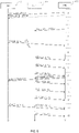
- Fig. 7 shows further a typical sequence of processes for performing UL transmissions on the basis of the IUA-UL grant. Also the processes of Fig. 7 involve the UE 10 and the eNB 100.
- the eNB 100 sends a IUA-UL grant 701 to the UE 10.
- the IUA-UL grant 701 indicates UL radio resources allocated to the UE 10 in reoccurring time intervals. In the example of Fig. 7 , it is assumed that these IUA UL radio resources are allocated in each subframe.
- the IUA-UL grant 701 may be sent on the PDCCH.
- the UE 10 then performs an initial IUA-UL transmission with an IUA-UL grant acknowledgement 702. If the UE 10 has no UL data to transmit, the IUA-UL grant acknowledgement 702 may be a IUA-UL transmission with padding. The IUA-UL grant acknowledgement 702 confirm receipt of the IUA-UL grant 701 to the eNB 100. If the IUA-UL grant acknowledgement 702 is not received by the eNB 100, the eNB 100 may resend the IUA-UL grant 701. The usage of the IUA-UL grant acknowledgement 702 is optional and may for example be configured during connection configuration, e.g., by the control information 201 of Fig. 2 .
- the IUA-UL grant 701 may be valid for an open time period, e.g., until de-configured by the eNB 100. Alternatively, also a validity period could be indicated together with the IUA-UL grant 701 or in separate control information, such as the control information 201 of Fig. 2 .
- the UE 10 may prepare one or more IUA-UL transmissions on the allocated UL radio resources of the IUA-UL grant.
- Fig. 7 also illustrates a corresponding processing time, e.g., associated with layer 2 and layer 1 processing. If a BSR is triggered, the UE 10 may also add the BSR to the IUA-UL transmissions.
- the UE 10 then sends the IUA-UL transmission(s) 704, 705 at the next time intervals with UL radio resources indicated by the IUA-UL grant.
- the eNB 100 When the eNB 100 receives the IUA-UL transmissions 704, 705 it may evaluate the included BSR to decide whether sending of one or more D-UL grants to the UE 10 is appropriate, e.g., using processes as explained in connection with Fig. 6 .
- the eNB 100 sends D-UL grants 706 and 707 to the UE 10.
- these D-UL grants 706, 707 may be accompanied by HARQ feedback with respect to the IUA-UL transmissions 704, 705.
- the UE 10 and the eNB 100 may accomplish link adaptation of the radio link between the UE 10 and the eNB 100, e.g., by selecting a suitable modulation and coding scheme (MCS) and/or transmission power, as per the claims.
- MCS modulation and coding scheme
- This link adaptation phase may last for about one HARQ roundtrip time, e.g., eight subframes. After that, a higher performance may be achieved due to optimized link adaptation.
- the UE 10 may then continue performing UL transmissions on the further allocated radio resources indicated by the D-UL grants 706, 707, as illustrated by D-UL transmissions 708 and 709.
- the D-UL transmissions 708, 709 may each include a BSR, so that further D-UL grants may be issued to the UE 10 as long as it has UL data for transmission.
- the IUA-UL grant and D-UL grants may be utilized in parallel.
- the IUA-UL grant may be utilized to provide a basic allocation of UL radio resources which allows for fast initial access without a preceding scheduling request.
- the D-UL grants may in turn be utilized provide further allocated UL radio resources if there is a higher traffic demand by the UE 10.
- utilization of the D-UL grants may be prioritized over the utilization of the IUA-UL grant in time intervals where both types of grants indicate allocated UL radio resources. This prioritization may for example be achieved by performing the check of step 540 in Fig. 5 .
- the eNB 100 may first provide a D-UL grant to the UE 10', and the UE 10' may perform a D-UL transmission in the UL radio resources allocated by the D-UL grant.
- a delay between providing the D-UL grant to the UE 10' and the D-UL transmission by the UE 10' may be four TTIs. In this time interval, the eNB 100 may provide a IUA-UL grant to the UE 10.
- the eNB 100 allocates at least a part or all these UL radio resources by the IUA-UL grant to the UE 10. Now assuming that the UL transmission of the UE 10' on the UL radio resources allocated by the D-UL grant fails, a retransmission by the UE 10' on the same UL radio resources by the UE 10' will be triggered.
- the retransmission by the UE 10' is performed eight TTIs from the initial UL transmission, i.e., at a time when at least a part of the UL radio resources previously allocated by the D-UL grant to the UE 10' is now allocated by the IUA-UL grant to the UE 10. Accordingly, the retransmission by the UE 10' may collide with a IUA-UL transmission by the UE 10.
- While such collision may be avoided by simply not including the UL radio resources allocated by the D-UL grant to the UE 10' in the later IUA-UL grant to the UE 10, such selection of UL radio resources to be allocated by the IUA-UL grant may be too restrictive and excessively limit the availability of UL resources to be allocated by the IUA-UL grant. Specifically, such selection would also exclude UL radio resources in which a retransmission does actually not occur because the initial D-UL transmission is successful.
- the eNB 100 detects the need of a retransmission on the UL radio resources allocated by the IUA-UL grant and then controls the communication device, to which the UL radio resources are allocated by the IUA-UL grant, to disable utilization of at least a part of the UL radio resources allocated by the IUA-UL grant, at least in the time interval when the retransmission is going to happen. As per the claims, this temporary disabling of the utilization is achieved by sending corresponding control information to the communication device.
- the control information may be sent on a DL control channel, e.g., a PDCCH of the LTE radio access technology, utilizing a similar mechanism or format as for sending the D-UL grants or the IUA-UL grant.
- a part of the control information could also be provided by other control signaling, e.g., by an RRC message.
- a duration of time period for which the utilization of the UL radio resources allocated by the IUA-UL grant is to be disabled and/or an offset between transmission of the control information and the disabling of the utilization could be indicated beforehand by such other control signaling to the communication device, e.g., in the configuration information 201 of Fig. 2 , and then be applied when the disabling is triggered by a message on the DL control channel.
- the disabling is triggered by a DCI (DL control information) message on the PDCCH which utilizes the same or a similar format as applied for sending the D-UL grants or IUA-UL grants, and such control message is referred to as a "hold grant".
- the hold grant may be valid for a specific TTI, e.g., defined by a number of TTIs from receipt of the hold grant.
- the hold grant could trigger the disabling of the utilization of the allocated UL radio resources in the fourth TTI from reception of the hold grant.
- the hold grant could also include further information specifying a number of TTIs for which the utilization of the allocated UL radio resources is to be disabled.
- the hold grant could be valid until further control information is received to re-enable the utilization of the allocated UL radio resources, e.g., in the form of a further hold grant or other DCI message. If merely the disabling is to be triggered, the hold grant can be indicated by a single bit in the DCI.
- the hold grant may apply to all UL radio resources allocated by the IUA-UL grant. In such cases, when the communication device receives a hold grant with respect to a certain time interval, it will not perform a IUA-UL transmission. In other scenarios, the hold grant may specify the UL radio resources of which utilization is to be disabled. If these include only a part of the UL radio resources allocated by the IUA-grant, the communication device may continue utilization on the other part of the UL radio resources allocated by the IUA-UL grant, i.e., may send a IUA-UL transmission on the other part of the UL radio resources.
- one or more other communication devices may have received a IUA-UL grant allocating UL radio resources on which the retransmission is going to happen.
- the hold grant could be addressed as a broadcast message to these multiple communication devices.
- This addressing could be achieved by utilizing a specific C-RNTI assigned to the multiple communication devices.
- Such C-RNTI could be preconfigured in the communication device or could be indicated to the communication device in configuration information, e.g., in the configuration information 201 of Fig. 2 .
- Fig. 8 illustrates exemplary processes in which a collision on resources allocated by a IUA-UL grant is avoided in accordance with the above concepts.
- the processes which encompass the claims, involve the UE 10 (UE 1), the further UE 10' (UE 2), and the eNB 100.
- UE 1 the UE 10
- UE 2 the further UE 10'
- eNB 100 the eNB 100
- TTIs a sequence of TTIs (0 to 13) is indicated on the right hand side of Fig. 9 .
- Each TTI may have a duration of 1 ms, corresponding to the duration of one subframe in the LTE radio access technology.
- the eNB 100 sends a D-UL grant 801 to the UE 10'. This may be accomplished on the PDCCH and in response to a scheduling request by the UE 10' or in response to a BSR from the UE 10'.
- the D-UL grant is sent in TTI 0.
- the D-UL grant 801 allocates UL radio resources in a single TTI to the UE 10'. This TTI is four TTIs after sending the D-UL grant, i.e., in TTI 4.
- the eNB 100 may also send a IUA-UL grant 802 to the UE 10' (in TTI 0 or some other TTI), e.g., on the PDCCH.
- the IUA-UL grant 802 may allocate UL radio resources in reoccurring time intervals to the UE 10', e.g., in each TTI.
- potential actions concerning the IUA-UL grant 802 are not illustrated in Fig. 8 .
- the eNB 100 sends a IUA-UL grant 803 to the UE 10, e.g., on the PDCCH.
- the IUA-UL grant 803 allocates UL radio resources in reoccurring time intervals the UE 10.
- the IUA-UL 803 grant allocates the UL radio resources in each TTI (starting from TTI 6).
- other periodicities could be utilized as well, e.g., every second or third TTI.
- the IUA-UL 803 grant is sent in TTI 2, when the eNB 100 may regard the UL radio resources allocated by the D-UL grant 801 to the UE 10' as being available for allocation by the IUA-UL grant 802, because the earliest possible TTI when the UE 10 may utilize the UL radio resources allocated by the IUA-UL grant 803 (TTI 6) is after the TTI with the UL radio resources allocated by the D-UL grant 801 (TTI 4). Accordingly, the eNB 100 allocates at least a part of the UL radio resources, which were previously allocated by the D-UL grant 801 to the UE 10', by the IUA-UL 803 grant to the UE 10, thereby enabling efficient reuse of the UL radio resources.
- the D-UL grant 801 pertains to a TTI in which the UL radio resources allocated by the IUA-UL grant 803 are not yet utilized, there is no actual overlap of the UL radio resources allocated by the D-UL grant 801 and the IUA-UL grant 803, even though the D-UL grant 801 and the IUA-UL grant 803 may indicate the same or overlapping RBs.
- the UE 10' then performs a D-UL transmission 804 in the UL radio resources allocated by the D-UL grant 801.
- the D-UL transmission 804 is sent in TTI 4.
- the D-UL transmission 804 may include UL data and/or a BSR.
- the D-UL transmission 804 fails, i.e., is not successfully received by the eNB 100. This failure may for example be due to interference or some other disturbance. The failure is detected by the eNB 100 as part of the HARQ processing at the eNB 100.
- the UE 10 may perform an IUA-UL transmission 805 in TTI 6, an IUA-UL transmission 806 in TTI 7, and/or an IUA-UL transmission 807 in TTI 8. Further, as per the claims, in each of these TTIs the UE 10 may also select the inactive mode and perform no IUA-UL transmission.
- the eNB 100 sends a hold grant 808 to the UE 10 and a HARQ NACK the UE 10'.
- the hold grant 808 and the HARQ NACK 809 are sent in response to detecting the failure of the D-UL transmission 804.
- the HARQ NACK 809 has the purpose of triggering a retransmission of the D-UL transmission 804 by the UE 10'.
- the hold grant 808 has the purpose of avoiding a collision of this retransmission with a IUA-UL transmission by the UE 10.
- the retransmission is performed on the same UL radio resources as used for the D-UL transmission 804, i.e., the UL radio resources allocated by the D-UL grant 801.
- the hold grant 808 disables utilization of these UL radio resources on the basis of the IUA-UL grant 803 by the UE 10 in the TTI of the retransmission, which in the illustrated example is TTI 12.
- the UE 10 may perform an IUA-UL transmission 810 in TTI 9, an IUA-UL transmission 811 in TTI 10, and/or an IUA-UL transmission 812 in TTI 11. Further, in each of these TTIs the UE 10 may also select the inactive mode and perform no IUA-UL transmission. However, in TTI 12 a potential IUA-UL transmission 813 by the UE 10 is prevented by the hold grant. The UE 10 may thus perform the retransmission of the D-UL transmission 804 (denoted by D-UL RTX 814), without a risk of a collision with the potential IUA-UL transmission 813.
- the chances of the retransmission 814 being successful are thus improved and worsening the latency experienced by the UE 10' by a further time period of eight TTIs (until the next possible retransmission) can be avoided.
- TTI 13 the UE 10 may again perform an IUA-UL transmission 815. Therefore there is only a small potential worsening of the latency experienced by the UE 10, corresponding to one TTI when assuming a need for a IUA-UL transmission in TTI 12.
- the hold grant 808 has no impact on the latency experienced by the UE 10.
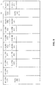
- Fig. 9 schematically illustrates an exemplary allocation of UL radio resources underlying the processes of Fig. 8 .
- Fig. 9 shows a possible allocation of UL radio resources in TTIs 4 to 13.
- the UL radio resources allocated by the D-UL grant 801 to the UE 10' are referred to as "D-RB UE2".
- the UL radio resources allocated by IUA-UL grant 802 to the UE 10' are referred to as "IUA-RB UE2".
- the UL radio resources allocated by IUA-UL grant 803 to the UE 10 are referred to as "IUA-RB UE1".
- the UL radio resources of the initial UL transmission in TTI 4 and the associated retransmission in TTI 12 are further marked with "(RX)" and "(RTX)", respectively.
- UL radio resources are allocated to the UE 10' only.
- UL radio resources are allocated to both the UE 10' and the UE 10.
- TTI 12 the allocation of the UL radio resources to the UE 10 by the IUA-UL grant is disabled, so that these UL radio resources can be utilized by the UE 10' for performing the retransmission.
- a HARQ roundtrip time of eight TTIs from performing the initial UL transmission to performing the retransmission is assumed.
- similar processes could also be based on a shorter or longer HARQ roundtrip time.
- other delays between receiving the D-UL grant and the D-UL transmission on the UL radio resources allocated by D-UL grant and/or other delays between receiving the IUA-UL grant and the first occasion for a IUA-UL transmission on the UL radio resources allocated by IUA-UL grant could be utilized.
- the utilization of the hold grant is not limited to avoiding collisions for a retransmission of a D-UL transmission on UL radio resources allocated by a D-UL grant.
- the hold grant could also be utilized for avoiding a collision between a retransmission of a IUA-UL transmission, e.g., when IUA-UL grants are utilized for allocating the same or overlapping UL radio resources to different communication devices.
- the D-UL grant 801 could be omitted and the initial UL transmission 804 in TTI 4 could be a IUA-UL transmission on UL radio resources allocated by the IUA-UL grant 802.
- the hold grant 808 may be utilized to avoid a collision between the retransmission of the IUA-UL transmission in TTI 12 and the potential IUA-UL transmission 813 in TTI 12.
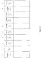
- Fig. 10 schematically illustrates an exemplary allocation of UL radio resources when assuming such overlapping allocation of UL radio resources to the UE 10 and the UE 10'.
- Fig. 10 shows a possible allocation of UL radio resources in TTIs 4 to 13.
- the UL radio resources allocated by the IUA-UL grant 802 to the UE 10' are referred to as "IUA-RB UE2".
- the UL radio resources allocated by IUA-UL grant 803 to the UE 10 are referred to as "IUA-RB UE1".
- the UL radio resources of the initial UL transmission in TTI 4 and the associated retransmission in TTI 12 are further marked with "(RX)" and "(RTX)", respectively.
- UL radio resources are allocated to the UE 10' only.
- overlapping UL radio resources are allocated to both the UE 10' and the UE 10.
- the allocation of the UL radio resources to the UE 10 by the IUA-UL grant 803 is disabled, so that these UL radio resources can be utilized by the UE 10' for performing the retransmission.
- the retransmission 814 may be prioritized over the potential new IUA-UL transmission 813 in TTI 12, so that undue worsening of the latency experienced by the UE 10' can be avoided.
- An overlapping allocation of UL radio resources as assumed in the example of Fig. 10 may be efficient if the UL radio resources allocated by the IUA-UL grant being utilized in a conditional manner, e.g., as explained above by selecting between the active mode and the inactive mode. Due to the conditional utilization a IUA-UL transmission is not performed on every possible occasion, which means that there is only a certain probability of a conflict of IUA-UL transmissions by the UE 10 and the UE 10', which may be tolerable.
- Fig. 11 shows a flowchart for illustrating method which may be used to consider the hold grant in the operation of a communication device, such as the UE 10. If a processor based implementation of the communication device is used, the steps of the method may be performed by one or more processors of the communication device. For this purpose, the processor(s) may execute correspondingly configured program code. Further, at least some of the corresponding functionalities may be hardwired in the processor(s).
- the communication device may check if UL data are available for transmission. If this is not the case, the method may return to step 1110 for the next TTI, as indicated by branch "N". If UL data are found to be available for transmission, the method may continue with step 1120, as indicated by branch "Y".
- the communication device may check if a D-UL grant for the present TTI was received by the communication device. If this is the case, the method may proceed with step 1130, as indicated by branch "Y".
- the UL radio resources allocated by the D-UL grant may be utilized for performing a D-UL transmission with at least a part of the UL data.
- This D-UL transmission may also include a BSR. The method may then return to step 1110 for the next TTI.
- step 1120 If at step 1120 it is found that no D-UL grant for the present TTI was received by the communication device, the method may proceed with step 1140, as indicated by branch "N".
- the communication device may check if a IUA-UL grant valid for the present TTI was received by the communication device. If this is not case, the method may proceed with step 1150, as indicated by branch "N".
- the communication device may send a scheduling request to obtain an allocation of UL radio resources for sending the available UL data.
- the method may then return to step 1110 for the next TTI.
- step 1140 If at step 1140 it is found that a IUA-UL grant valid for the present TTI was received by the communication device, the method may proceed with step 1160, as indicated by branch "Y".
- the communication device may check if a hold grant for the present TTI was received by the communication device. If this is not case, the method may proceed with step 1170, as indicated by branch "N".
- the UL radio resources allocated by the IUA-UL grant may be utilized for performing a IUA-UL transmission with at least a part of the UL data.
- This IUA-UL transmission may also include a BSR. The method may then return to step 1110 for the next TTI.
- step 1160 If at step 1160 it is found that a hold grant for the present TTI was received by the communication device, the method may proceed with step 1180, as indicated by branch "Y".
- the communication device does not utilize the UL radio resources to which the hold grant pertains. This may involve entirely refraining from performing an IUA-UL transmission in the UL radio resources indicated in the IUA-UL grant. In some cases, e.g., if the hold grant disables only a part of the UL radio resources indicated in the IUA-UL grant, the communication device may also perform a IUA-UL transmission on the other part of the UL radio resources, which was not disabled by the hold grant.
- step 1180 the method may return to step 1130 for the next TTI.
- Fig. 12 shows a flowchart for illustrating a method of controlling radio transmission in a cellular network.
- the method may be used for implementing the above-described concepts in a node of the cellular network, e.g., in a node which is responsible for scheduling transmissions, such as the eNB 100 or an RNC when using the UMTS radio access technology.
- a processor based implementation of the node the steps of the method may be performed by one or more processors of the node.
- the processor(s) may execute correspondingly configured program code. Further, at least some of the corresponding functionalities may be hardwired in the processor(s).
- the node sends a UL grant to a communication device, e.g., to the UE 10.
- the node may send the UL grant on a DL control channel, e.g., a PDCCH of the LTE radio access technology.
- the UL grant indicates UL radio resources allocated to the communication device in reoccurring time intervals. Examples of such UL grant are the IUA-UL grants 203, 701, 802, and 803. Further, the UL grant could also correspond to another type of long lasting grant, e.g., an SPS grant.
- the time intervals may reoccur periodically. However, other patterns of reoccurrence could be utilized as well.
- a periodicity in which the time intervals reoccur may be indicated in the UL grant or in separate control information transmitted to the communication device, such as in the configuration information 201 of Fig. 2 .
- the time intervals may correspond to TTIs in which radio transmission in the cellular network is organized.
- the radio transmission may be organized in radio frames each subdivided into subframes, and the time intervals may correspond to subframes.
- the allocated UL radio resources may be radio resources of a UL data channel, such as a PUSCH of the LTE radio access technology.
- the node may send the UL grant in response to detecting a change of a connection status of the communication device, e.g., when the communication device enters the cellular network and connects thereto, when the communication device enters a different cell or area of the cellular network, or the like. Further, the node may send the UL grant according to a periodic schedule, e.g., every minute or hour. In each case, no request for the UL grant by the communication device is required.
- the node selects between an active mode and an inactive mode.
- the communication device performed a UL transmission in the allocated UL radio resources.
- the inactive mode the communication device performed no UL transmission in the allocated UL radio resources.
- the node decides for each of the time intervals whether the communication device performed a transmission on the allocated UL radio resources. This may for example be accomplished by detecting signals from the communication device in the allocated UL radio resources. In response to detecting no signals from the communication device in the allocated UL radio resources, the node may select the inactive mode. In response to detecting signals from the communication device in the allocated UL radio resources, the node may select the active mode.
- the node detects a need for a UL retransmission by a further communication device, such as the UE 10, in one of the time intervals and in at least a part of the UL radio resources allocated by the UL grant of step 1210.
- the node may detect the need for a UL retransmission by first detecting a failed transmission by the further communication device in this part of the UL radio resources allocated by the UL grant of step 1210.
- the node may also conclude that there is a need for a UL retransmission. Detecting the need for a retransmission may be part of requesting the retransmission in a HARQ process. That is to say, when sending a HARQ NACK, such as the HARQ NACK 809 of Fig. 8 , the node may also assume that there will be a retransmission.
- the UL radio resources allocated by the UL grant of step 1210 may be overlapping with UL radio resources which are allocated by a further UL grant to the further communication device, e.g., as explained in connection with the scenario of Fig. 10 .
- the node may send control information to the communication device.
- the control information temporarily disables utilization, by the communication device, of at least that part of the allocated UL radio resources in which the retransmission is expected.
- the utilization is disabled in at least that time interval in which the retransmission is expected.
- the control information may disable the utilization for a configured time period, e.g., for a subframe or TTI, or for a configured number of subframes or TTIs. Such time period may also be indicated by the control information.
- the control information may also indicate the UL radio resources of which the utilization by the communication device is disabled, e.g., in terms of RBs.
- the node may send the control information on a DL control channel between the node and the communication device, e.g., on a PDCCH of the LTE radio access technology.
- the node may send the control information in a broadcast message addressed to a plurality of communication devices, e.g., by utilizing a group C-RNTI to address the communication device and other communication devices.
- An example of such control information is the above-mentioned hold grant.
- the node may send further control information to the communication device.
- the further control information may re-enable the utilization of the allocated UL radio resources by the communication device. Similar to the control information of step 1230, the further control information may indicate the UL radio resources of which the utilization by the communication device is re-enabled, e.g., in terms of RBs, and/or the node may send the further control information on the DL control channel between the node and the communication device, e.g., the PDCCH of the LTE radio access technology.
- the node may send the further control information in a broadcast message addressed to a plurality of communication devices, e.g., by utilizing a group C-RNTI to address the communication device and other communication devices.
- Fig. 13 shows a flowchart for illustrating a method of controlling radio transmission in a cellular network.
- the method may be used for implementing the above-described concepts in a communication device with connectivity to the cellular network, e.g., the UE 10.
- the steps of the method may be performed by one or more processors of the communication device.
- the processor(s) may execute correspondingly configured program code. Further, at least some of the corresponding functionalities may be hardwired in the processor(s).
- the communication device receives a UL grant from the cellular network, e.g., from the eNB 100.
- the communication device may receive the UL grant on a DL control channel, e.g., a PDCCH of the LTE radio access technology.
- the UL grant indicates UL radio resources allocated to the communication device in reoccurring time intervals. Examples of such UL grant are the IUA-UL grants 203, 701, 802, and 803. Further, the UL grant could also correspond to another type of long lasting grant, e.g., an SPS grant.
- the time intervals may reoccur periodically. However, other patterns of reoccurrence could be utilized as well.
- a periodicity in which the time intervals reoccur may be indicated in the UL grant or in separate control information transmitted to the communication device, such as in the configuration information 201 of Fig. 2 .
- the time intervals may correspond to TTIs in which radio transmission in the cellular network is organized.
- the radio transmission may be organized in radio frames each subdivided into subframes, and the time intervals may correspond to subframes.
- the allocated UL radio resources may be radio resources of a UL data channel, such as a PUSCH of the LTE radio access technology.
- the UL radio resources allocated by the UL grant of step 1310 may be overlapping with UL radio resources which are allocated by a further UL grant to a further communication device, e.g., the UE 10'.
- a further communication device e.g., the UE 10'.
- the communication device selects between an active mode and an inactive mode.
- the communication device performs a UL transmission in the allocated UL radio resources.
- the communication device performs no UL transmission in the allocated UL radio resources. Accordingly, the utilization of the UL radio resources allocated by the UL grant of step 1610 is conditional.
- the selection may involve that the communication device checks whether UL data is available for transmission by the communication device. In response to UL data being available for transmission, the communication device may select the active mode to perform a UL transmission which includes at least a part of the UL data.
- the communication device may also send a scheduling request to the cellular network, thereby requesting allocation of further UL radio resources to the communication device.
- a scheduling request is the scheduling request 303.
- the selection may also involve that the communication device checks whether one or more conditions for sending a BSR, indicating an amount of UL data available for transmission by the communication device, are met. In response to one or more of such conditions being met, the communication device may selecting the active mode to send a UL transmission including the BSR.
- the communication device receives control information from the cellular network, e.g., from the eNB 100.
- the communication device may receive the control information on a DL control channel between the node and the communication device, e.g., on a PDCCH of the LTE radio access technology.
- the communication device may receive the control information in a broadcast message addressed to a plurality of communication devices, e.g., by a group C-RNTI assigned to the communication device and to other communication devices.
- An example of such control information is the above-mentioned hold grant.
- the communication device in response to the control information of step 1330, temporarily disables its utilization of at least a part of the allocated UL radio resources in a certain time interval. In this part of the allocated UL radio resources and this time interval a retransmission by a further communication device may be expected.
- the disabling of the utilization may involve disabling the utilization for a configured time period, e.g., for a subframe or TTI, or for a configured number of subframes or TTIs. Such time period may be indicated by the control information of step 1230.
- the control information of step 1230 may also indicate the UL radio resources of which the utilization is disabled by the communication device, e.g., in terms of RBs.
- the communication device may receive further control information from the cellular network, e.g., from the eNB 100. Similar to the control information of step 1330, the communication device may receive the control information on the DL control channel between the node and the communication device, e.g., on the PDCCH of the LTE radio access technology. In some scenarios, the communication device may receive the further control information in a broadcast message addressed to a plurality of communication devices, e.g., by a group C-RNTI assigned to the communication device and to other communication devices.
- the communication device re-enables its utilization of the allocated UL radio resources. This may be accomplished in response to expiry of the configured time period as indicated in the control information of step 1330. Further, this may be accomplished in response to the further control information of step 140. In the latter case, the further control information may also indicate the UL radio resources of which the utilization by the communication device is re-enabled, e.g., in terms of RBs. This indication of specific UL radio resources in the further control information also allows scenarios where not all disabled UL radio resources are re-enabled at the same time.
- Figs. 12 and 13 may be combined, e.g., in a system including a node operating according to the method of Fig. 12 and a communication device operating according to the method of Fig. 13 .
- Fig. 14 illustrates exemplary structures which may be used for implementing the above concepts in a node of a cellular network, e.g., the eNB 100.
- the node may include an interface 1410 for connecting to communication devices, e.g., to the UEs 10, 10'.
- the interface 1410 may be utilized for sending the above-mentioned UL grants or for receiving UL transmissions. Further, the interface 1410 may be utilized sending the above-mentioned control information to the communication devices and/or for receiving control information from the communication devices.
- the interface 1410 may be a radio interface for establishing radio links to the communication devices.
- the node is implemented as a control node of a base station, such as an RNC of the UMTS radio access technology, the interface 1410 may be used for controlling the base station and for sending or receiving transmissions of the communication devices via the base station.
- the node includes one or more processors 1450 coupled to the interface 1410, and a memory 1460 coupled to the processor(s) 1450.
- the memory 1460 may include a Read Only Memory (ROM), e.g., a flash ROM, a Random Access Memory (RAM), e.g., a Dynamic RAM (DRAM) or Static RAM (SRAM), a mass storage, e.g., a hard disk or solid state disk, or the like.
- ROM Read Only Memory
- RAM Random Access Memory
- DRAM Dynamic RAM
- SRAM Static RAM
- the memory 1460 includes suitably configured program code to be executed by the processor(s) 1450 so as to implement the above-described functionalities of the communication device.
- the memory 1460 may include various program code modules for causing the node to perform processes as described above, e.g., corresponding to the method steps of Fig. 13 .
- the memory 1460 may include a IUA control module 1470 for implementing the above-described functionalities of determining a UL grant allocating UL resources in reoccurring time intervals and controlling the utilization of such UL grant by sending control information for temporarily disabling the utilization of the UL radio resources allocated by such grant.
- the memory 1460 may include a dynamic scheduling module 1480 for implementing the above-described functionalities of dynamically sending UL grants with respect to a certain time interval.
- the memory 1460 may include a control module 1490 for implementing generic control functionalities, e.g., controlling reporting or other signaling, such as detecting failed of transmissions and requesting retransmissions, e.g., as part of a HARQ process.
- generic control functionalities e.g., controlling reporting or other signaling, such as detecting failed of transmissions and requesting retransmissions, e.g., as part of a HARQ process.
- the structures as illustrated in Fig. 14 are merely schematic and that the node may actually include further components which, for the sake of clarity, have not been illustrated, e.g., further interfaces or processors.
- the memory 1460 may include further types of program code modules, which have not been illustrated, e.g., program code modules for implementing known functionalities of an eNB or RNC.
- a computer program may be provided for implementing functionalities of the node, e.g., in the form of a physical medium storing the program code and/or other data to be stored in the memory 1460 or by making the program code available for download or by streaming.
- Fig. 15 illustrates exemplary structures which may be used for implementing the above concepts in a communication device, e.g., the UE 10.
- the communication device may include an interface 1510 for connecting to a cellular network.
- the interface may correspond to a radio interface as specified for the LTE radio access technology or based on another radio access technology, such as the UMTS radio access technology.
- the interface 1510 may be utilized for receiving the above-mentioned UL grants or for sending UL transmissions. Further, the interface 1510 may be utilized for receiving the above-mentioned control information from the cellular network or sending control information to the cellular network.
- the communication device includes one or more processors 1550 coupled to the interface 1510, and a memory 1560 coupled to the processor(s) 1550.
- the memory 1560 may include a ROM, e.g., a flash ROM, a RAM, e.g., a DRAM or SRAM, a mass storage, e.g., a hard disk or solid state disk, or the like.
- the memory 1560 includes suitably configured program code to be executed by the processor(s) 1550 so as to implement the above-described functionalities of the communication device.
- the memory 1560 may include various program code modules for causing the communication device to perform processes as described above, e.g., corresponding to the method steps of Fig. 13 .
- the memory 1560 may include a IUA control module 1570 for implementing the above-described functionalities of conditionally utilizing the UL radio resources allocated in reoccurring time intervals and for temporarily disabling the utilization of the UL radio resources in response to control information from the cellular network. Further, the memory 1560 may include a transmission control module 1580 for implementing the above-described functionalities of controlling the sending of UL transmissions from the communication device, e.g., on the UL radio resources in the reoccurring time intervals. Further, the memory 1560 may include a control module 1590 for implementing generic control functionalities such as controlling reporting or other signaling, or controlling retransmissions, e.g., as part of a HARQ process.
- generic control functionalities such as controlling reporting or other signaling, or controlling retransmissions, e.g., as part of a HARQ process.
- the structures as illustrated in Fig. 15 are merely schematic and that the communication device may actually include further components which, for the sake of clarity, have not been illustrated, e.g., further interfaces or processors.
- the memory 1560 may include further types of program code modules, which have not been illustrated, e.g., program code modules for implementing known functionalities of a UE.
- a computer program may be provided for implementing functionalities of the communication device, e.g., in the form of a physical medium storing the program code and/or other data to be stored in the memory 1560 or by making the program code available for download or by streaming.
- the concepts as described above may be used for achieving a low latency for UL transmissions by a communication device while at the same time providing a low risk of colliding UL transmissions. Specifically, by temporarily disabling the utilization of the UL radio resources allocated in reoccurring time intervals, retransmissions may be performed with low collision risk.
- the examples and embodiments as explained above are merely illustrative and susceptible to various modifications.
- the concepts of collision avoidance as explained for the IUA-UL grant may also be applied in connection with various types of long lasting grants, e.g., SPS grants.
- the illustrated nodes may be implemented by a single device or by a system of multiple devices.
- the above concepts may be implemented by using correspondingly designed software to be executed by one or more processors of an existing device, or by using dedicated device hardware.
Landscapes
- Engineering & Computer Science (AREA)
- Computer Networks & Wireless Communication (AREA)
- Signal Processing (AREA)
- Mobile Radio Communication Systems (AREA)
Description
- The present invention relates to methods for controlling radio transmission in a cellular network and to corresponding devices.
- In cellular networks, allocation of radio resources to a certain user equipment (UE), also referred to as scheduling, is typically accomplished dynamically on the network side. In the downlink (DL) direction from the cellular network to the UE, a network node may allocate radio resources in accordance with a need to transmit DL data to the UE. The network node may then inform the UE about the allocated resources by sending a DL assignment. For the uplink (UL) direction from the UE to the cellular network, a scheduling request which is sent by the UE to the cellular network may be used to indicate that the UE needs radio resources for sending UL data. For example, in the LTE (Long Term Evolution) radio access technology specified by 3GPP (3rd Generation Partnership Project), a base station of the LTE radio access technology, referred to as "evolved Node B" (eNB) is responsible for the scheduling. This may be accomplished dynamically, taking into account the instantaneous traffic pattern and radio propagation characteristics of each UE.
- In the dynamic scheduling process of the LTE radio access technology a UE which needs to send UL data may first send a scheduling request to an eNB which serves the cell of the UE. The scheduling request may be sent on a UL control channel, referred to as PUCCH (Physical UL Control Channel), providing dedicated resources for sending scheduling requests by the UE. Alternatively, the scheduling request may be sent on a contention based random access channel (RACH). The eNB then allocates UL radio resources to the UE. The allocated UL radio resources are indicated in a UL grant, which is sent from the eNB to the UE. A separate UL grant is sent for each subframe or TTI (Transmission Time Interval) of 1 ms. On the allocated UL radio resources, the UE may then send UL data to the eNB. In addition, the UE may also send a buffer status report (BSR) indicating the amount of buffered UL data still to be sent by the UE.
- In the above process of transmitting the UL data, latency occurs which is due to the sending of the scheduling request before the UE can proceed with the transmission of the UL data. However, such delay is not desirable in many cases. For example, certain data traffic may be sensitive to latency, such as data traffic associated with online gaming.
- A technology which may be used for achieving a reduced latency is Semi-Persistent Scheduling (SPS) as specified in 3GPP TS 36.321 V12.2.1 (2014-06). In SPS, UL radio resources are periodically allocated to the UE by sending a long lasting grant which covers multiple TTIs by allocating UL radio resources in a pattern of TTIs with configurable periodicity. By utilizing SPS, the need to send scheduling requests may be reduced.
- However, the utilization of such long lasting grants may result in a risk of colliding transmissions on the same radio resources. For example, in the LTE radio access technology retransmissions according to a HARQ (Hybrid Automatic Repeat Request) protocol are typically performed on the same radio resources as the original transmission, however eight TTIs later. Accordingly, although an UL grant is issued with respect to a specific TTI, it may have an impact on later TTIs. The problem may be illustrated by the following scenario: A first UE performs an UL transmission on UL radio resources allocated by a conventional UL grant in a certain TTI. In one of the next TTIs, the eNB allocates these UL radio resources by a long lasting grant to another UE. After providing the long lasting grant to the second UE, the eNB detects failure of the UL transmission and sends a HARQ NACK (negative acknowledgement) to the first UE to trigger a retransmission by the first UE. This retransmission is typically performed on the same UL radio resources as the original UL transmission, eight TTIs later than the original UL transmission. Since the UL radio resources have in the meantime been allocated to the second UE by the long lasting grant, a collision of the retransmission by the first UE and an UL transmission by the second UE may happen.
- One possibility to avoid such collisions is to allocate only those UL radio resources for which no retransmission is expected. However, in the case of an allocation by a long lasting grant, such selection of radio resources may be limited by the availability of radio resources, specifically because the long lasting grant may be issued at a time when it is not yet known in which of the available radio resources a retransmission will actually happen.
-
US 2014/0177487 A1 describes overriding of multi-TTI scheduling messages. In this case, a data transmission based on a previous multi-TTI scheduling message may be adjusted, interrupted or terminated.US 2006/0291393 A1 describes a resource allocation method where resources assigned by a persistent assignment may be released for the duration of a nonpersistent assignment. - Accordingly, there is a need for techniques which allow for efficiently controlling radio transmissions in a cellular network, in particular with respect to avoiding collisions of UL transmissions or retransmissions on UL radio resources allocated by a long lasting grant.
- According to an embodiment of the invention, a method of controlling radio transmission in a cellular network is provided, as per
claim 1. - According to a further embodiment of the invention, a method of controlling radio transmission in a cellular network is provided, as per
claim 6. - According to a further embodiment of the invention, a node for a cellular network is provided, as per
claim 11. - According to a further embodiment of the invention, a communication device is provided, as per
claim 13. - According to a further embodiment of the invention, a computer program or computer program product is provided, as per claim 15.
- According to a further embodiment of the invention, a computer program or computer program product is provided, as per claim 16.
- Details of such embodiments and further embodiments will be apparent from the following detailed description of embodiments.
-
-
Fig. 1 schematically illustrates an exemplary cellular network environment with elements which may be involved in controlling UL transmissions. -
Fig. 2 schematically illustrates an exemplary process for performing UL radio transmissions . -
Fig. 3 schematically illustrates further exemplary process for performing UL radio transmissions. -
Fig. 4 schematically illustrates further exemplary process for performing UL radio transmissions. -
Fig. 5 shows a flowchart for illustrating a method which may be implemented by a communication device. -
Fig. 6 shows a flowchart for illustrating a method which may be implemented by a network node. -
Fig. 7 schematically illustrates an exemplary sequence of processes when for performing UL radio transmissions. -
Fig. 8 illustrates exemplary processes in which a collision of UL transmissions is avoided . -
Fig. 9 schematically illustrates an allocation of UL radio resources in the processes ofFig. 8 . -
Fig. 10 schematically illustrates a further example of allocation of UL radio resources in processes. -
Fig. 11 shows a flowchart for illustrating a method which may be used for implementing functionalities for avoiding collisions of UL transmissions in a communication device. -
Fig. 12 shows a flowchart for illustrating a method which may be implemented by a network node. -
Fig. 13 shows a flowchart for illustrating a further method which may be implemented by a communication device. -
Fig. 14 schematically illustrates structures of a network node. -
Fig. 15 schematically illustrates structures of a communication device. - In the following, concepts in accordance with exemplary embodiments of the invention will be explained in more detail and with reference to the accompanying drawings. The illustrated embodiments relate to concepts for controlling radio transmission in a cellular network. The embodiments specifically refer to a scenario using LTE radio access technology. However, it should be understood that the concepts could also be applied in connection with other radio access technologies, e.g., Universal Mobile Telecommunications System (UMTS) radio access technology.
- According to the illustrated concepts, UL transmissions from a communication device to the cellular network are performed on UL radio resources which may be allocated by two types of UL grants: first UL grants, in the following referred to as IUA-UL grant (IUA: Instant UL Access), which each indicate radio resources allocated to the communication device in reoccurring time intervals, and second UL grants, in the following referred to as dynamic UL grant (D-UL grant), which each indicate UL radio resources allocated to the communication device on a one time basis. The radio transmissions may be organized in radio frames each formed of a sequence of subframes, and the above-mentioned time intervals may correspond to the individual subframes. For example, in the LTE radio access technology the time intervals may correspond to TTIs or subframes of 1 ms duration. The IUA-UL grant may be provided to the communication device in preparation of a future UL transmission by the communication device, without any indication of a specific need to transmit UL data by the communication device. As compared to that, the D-UL grants are provided to the communication device in a dynamic manner, in particular on an as-needed basis. For example, a D-UL grant may be sent in response to a scheduling request by the communication device or in response to a BSR from the communication device. The IUA-UL grant and the D-UL grants may be sent on a DL control channel, such as a PDCCH (Physical DL control channel) of the LTE radio access technology. By means of the IUA-UL grants, a low latency associated with a UL transmission by the communication device may be provided. Specifically, on the UL radio resources indicated by the IUA-UL grant, the communication device may perform the UL transmission without previously indicating to the cellular network that there is a need to transmit UL data, e.g., by sending a scheduling request. Rather, the UL data can be transmitted in the next one of the reoccurring time intervals.
- In the illustrated concepts, the allocated UL radio resources indicated by the IUA-UL grant may be utilized in a conditional manner. Specifically, for each of the time intervals the communication device selects between an active mode and an inactive mode. In the active mode, the communication device performs a UL transmission on the allocated UL radio resources indicated by the IUA-UL grant. Conditions triggering the selection of the active mode may be a need to send UL data by the communication device or a need to send a BSR by the communication device. In the inactive mode, the communication device performs no UL transmission on the allocated UL radio resources indicated by the IUA-UL grant. The cellular network expects this behavior of the communication device and correspondingly selects between the active mode and the inactive mode. Specifically, the cellular network may detect that the communication device performed a UL transmission on the UL radio resources indicated by the IUA-UL grant and select the active mode to receive the UL transmission. If the UL transmission is received successfully, the cellular network may acknowledge this by sending a positive acknowledgement (ACK) to the communication device. If the UL transmission not received successfully, the cellular network may notify this by sending a negative acknowledgement (NACK) to the communication device. For example, sending of such ACKs or NACKs may be performed on the basis of a HARQ protocol, e.g., as defined for the LTE radio access technology. Further, the cellular network may detect that the communication device performed a UL transmission on the UL radio resources indicated by the IUA-UL grant and select the inactive mode. In the latter case, the cellular network may refrain from attempting to receive any UL transmission on the UL radio resources indicated by the IUA-UL grant or taking any further action concerning such UL transmission, e.g., sending of acknowledgements.
- By the conditional utilization of the UL radio resources indicated by the IUA-UL grant, it can be avoided that the communication device needs to perform a UL transmission in each time interval with UL radio resources allocated by the IUA-UL grant, which allows for energy efficient operation of the communication device and may also avoid unnecessary interference due to the UL transmissions on the UL radio resources indicated by the IUA-UL grant.
-
Fig. 1 illustrates exemplary elements which may be involved in implementing a corresponding control of a UL scheduling process. As examples of communication device which may connect to the cellular network,Fig. 1 illustratesUEs 10, 10'. TheUEs 10, 10' may each correspond to a mobile phone, a smartphone, a computer with wireless connectivity, or the like. As an example of a node of the cellular network which is responsible for controlling radio transmission by theUEs 10, 10',Fig. 1 illustrates abase station 100. In accordance with the assumed utilization of the LTE radio access technology, thebase station 100 will in the following also be referred to as eNB. TheeNB 100 is assumed to be responsible for performing the scheduling of UL transmissions, in particular providing the IUA-UL grants and providing the D-UL grants to theUEs 10, 10'. - It is to be understood that also other nodes may be involved in controlling at least a part of the UL scheduling process. For example, when utilizing the UMTS radio access technology, a control node referred to as RNC (Radio Network Controller) could implement similar functionalities as explained for the
eNB 100. -
Fig. 2 shows an exemplary processes of performing UL transmissions on the basis of the IUA-UL grant. The processes ofFig. 2 involve theUE 10 and theeNB 100. However, it is to be understood that similar processes could also involve the UE 10' and theeNB 100. - As illustrated, the
eNB 100 may send configuration information 201 to theUE 10. The configuration information 201 may for example indicate radio resources of a UL control channel which are allocated to theUE 10, e.g., radio resources of a PUCCH (Physical UL Control Channel). Further, the configuration information 201 could also provide various other kinds of information for establishing connectivity between theUE 10 and theeNB 100. The configuration information 201 may also indicate a configuration to be utilized by theUE 10 for various kinds of reporting to the cellular network, e.g., reporting of Channel State Information (CSI) or conditions for triggering a BSR. The configuration information 201 may for example be sent in an RRC (Radio Resource Control) message or by some other form of control signaling, e.g., in an MIB (Master Information Block) or SIB (System Information Block). - At
step 202, theeNB 100 may allocate UL radio resources to theUE 10. Specifically, theeNB 100 allocates these UL radio resources in reoccurring time intervals to theUE 10, e.g., in each subframe or in some other predefined sequence of subframes, such as in every second subframe, every third subframe, every fourth subframe, or the like. These UL radio resources may be radio resources of a PUSCH (Physical UL Shared Channel). - The
eNB 100 then sends an IUA-UL grant 203 to theUE 10. The IUA-UL grant 203 may be sent on the PDCCH. The IUA-UL grant 203 indicates the UL radio resources allocated atstep 202. For example, the allocated UL radio resources may be indicated in terms of one or more resource blocks (RBs). Further, the IUA-UL grant 203 may also indicate a periodicity in which the allocated UL radio resources reoccur. Alternatively, such periodicity could also be indicated by separate control information, e.g., the control information 201. InFig. 2 , the periodicity in which the allocated UL radio resources reoccur is indicated by P, corresponding to a time offset between two time intervals with UL radio resources allocated by the IUA-UL grant. In the following this time interval is also referred to as IUA period. - The IUA-
UL grant 203 may be provided with an indicator which allows theUE 10 to distinguish the IUA-UL grant 203 from other types of grants, e.g., a D-UL grant. Such indicator may for example be included in an information field of the IUA-UL grant 203. Further, the indicator could also be provided by utilizing a specific identifier to address the IUA-UL grant to theUE 10, e.g., a specific C-RNTI (Cell Radio Network Temporary Identity). For example, a one C-RNTI could be provided for addressing IUA-UL grants to theUE 10, and one or more other C-RNTIs could be provided for addressing other types of IUA-UL grants to theUE 10, such as D-UL grants. - After receiving the IUA-
UL grant 203, theUE 10 may enter an IUA operation, in which the UL radio resources indicated by theIUA UL grant 203 may be instantly utilized for performing low latency UL transmissions. In the IUA operation, theUE 10 checks for each of the time intervals with the allocated UL resources whether a condition for selecting the active mode is met. If this is the case, theUE 10 selects the active mode and performs a UL transmission on the allocated UL radio resources. If this is not the case, theUE 10 selects the inactive mode and performs no transmission on the allocated UL radio resources. - As illustrated by
step 204, in the first time interval with allocated UL resources indicated by the IUA-UL grant 203, theUE 10 may select the active mode to perform a UL transmission on the allocated resources which includes an acknowledgement (IUA-UL grant ACK) 205 of receipt of the IUA-UL grant 203 by theUE 10. The IUA-UL grant acknowledgement 205 may confirm to theeNB 100 that theUE 10 entered the IUA operation, which for example means that theeNB 100 should expect a UL transmission on the UL radio resources indicated by the IUA-UL grant 203. The IUA-UL grant acknowledgement 205 may for example correspond to a IUA-UL transmission with padding, i.e., without actual UL data but a predefined or random data pattern, such as only zeros. - As further illustrated by
steps UL grant 203, theUE 10 may select the inactive mode. In this case, theUE 10 performs no UL transmission on the allocated UL radio resources indicated by the IUA-UL grant (no IUA-UL TX), as indicated by the dashedarrows - As further illustrated by
step 210, in some time intervals with allocated UL radio resources indicated by the IUA-UL grant 203, theUE 10 may select the active mode to perform a UL transmission on the allocated UL radio resources indicated by the IUA-UL grant (IUA-UL TX) 211. Selecting the active mode atstep 210 may for example be triggered by a need for transmission of UL data by theUE 10. In such case, the IUA-UL transmission 211 may include at least a part of this UL data and a BSR. Selecting the active mode atstep 210 could also be triggered by a need to send a BSR by theUE 10, without a need for transmission of UL data. In such case, the IUA-UL transmission 211 may include the BSR, but no UL data. -
Fig. 3 shows further exemplary processes of performing UL transmissions on the basis of the IUA-UL grant. Also the processes ofFig. 3 involve theUE 10 and theeNB 100. The processes ofFig. 3 may for example be performed in the IUA operation of theUE 10, after receiving the IUA-UL grant. - As indicated by
step 301, in a certain time interval with allocated UL radio resources indicated by the IUA-UL grant, theUE 10 may select the active mode to perform a UL transmission of UL data on the allocated UL radio resources indicated by the IUA-UL grant, inFig. 3 illustrated by IUA-UL transmission 302 (which may also include a BSR). - In addition to sending the IUA-
UL transmission 302, theUE 10 may also send ascheduling request 303 to theeNB 100. - As indicated by
step 304, in response to thescheduling request 303 theeNB 100 performs allocation of furtherUL radio resources 304 to theUE 10. TheeNB 100 sends a D-UL grant 305 to theUE 10 which indicates these further allocated UL radio resources. - In the processes of
Fig. 3 , it is further assumed that the IUA-UL transmission 302 could not be successfully received by theeNB 100, e.g., due to poor radio link adaptation between theUE 10 and theeNB 100. Accordingly, theeNB 100 notifies theUE 10 of the failed reception by sending aHARQ NACK 306. - The
HARQ NACK 306 causes theUE 10 to retransmit the UL data on the further allocated UL radio resources indicated by the D-UL grant 305, as indicated by dynamic UL transmission (D-UL TX) 307. Similar to IUA-UL transmission 302, also the D-UL transmission 307 may include a BSR. - In the processes of
Fig. 3 , sending thescheduling request 305 together with the initial IUA-UL transmission 302 allows for avoiding additional delays if the IUA-UL transmission fails, i.e., for achieving a similar performance with respect to latency as in the case of utilizing only scheduling request based dynamic scheduling. -
Fig. 4 shows further exemplary processes of performing UL transmissions on the basis of the IUA-UL grant. Also the processes ofFig. 4 involve theUE 10 and theeNB 100. The processes ofFig. 4 may for example be performed in the IUA operation of theUE 10, after receiving the IUA-UL grant. - As indicated by step 401, in a certain time interval with allocated UL radio resources indicated by the IUA-UL grant, the
UE 10 may select the active mode to perform a UL transmission of UL data on the allocated UL radio resources indicated by the IUA-UL grant, inFig. 4 illustrated by IUA-UL transmission 402. As illustrated, the IUA-UL transmission 402 also includes a BSR. The BSR indicates an amount of further UL data pending for transmission by theUE 10. - As indicated by
step 403, on the basis of the BSR in IUA-UL transmission 402, theeNB 100 performs allocation of further UL radio resources to theUE 10. TheeNB 100 sends a D-UL grant 404 to theUE 10 which indicates these further allocated UL radio resources. - The
UE 10 may then transmit at least a part of the further UL data on the further allocated UL radio resources indicated by the D-UL grant 404, as indicated by D-UL transmission 405. Also D-UL transmission 405 includes a BSR which indicates an amount of further UL data pending for transmission by theUE 10. - As indicated by
step 406, on the basis of the BSR in D-UL transmission 405, theeNB 100 performs allocation of further UL radio resources to theUE 10. TheeNB 100 sends a further D-UL grant 407 to theUE 10 which indicates these further allocated UL radio resources. - The
UE 10 may then transmit at least a part of the further UL data on the further allocated UL radio resources indicated by the D-UL grant 407, as indicated by D-UL transmission 408. Again, D-UL transmission 408 includes a BSR which indicates an amount of further UL data pending for transmission by theUE 10. - As further illustrated, the
UE 10 may also perform a further IUA-UL transmission 409 at the later time interval with allocated UL radio resources indicated by the IUA-UL grant. Again, IUA-UL transmission 409 includes a BSR which indicates an amount of further UL data pending for transmission by theUE 10. - As can be seen from the processes of
Fig. 4 , the BSR in a IUA-UL transmission may trigger allocation of further UL radio resources which may then be indicated in a D-UL grant. These further allocated UL radio resources may then be used alternatively or in addition to the UL radio resources indicated by the IUA-UL grant for transmission of UL data. In this way, the amount of UL radio resources allocated to theUE 10 may be dynamically adapted to the current UL traffic demand of theUE 10, while at the same time allowing fast initial access to UL radio resources. -
Fig. 5 shows a flowchart for illustrating a method which may be utilized for controlling a communication device, e.g., theUE 10, to operate in accordance with the above-mentioned concepts. If a processor based implementation of the communication device is used, the steps of the method may be performed by one or more processors of the communication device. For this purpose, the processor(s) may execute correspondingly configured program code. Further, at least some of the corresponding functionalities may be hardwired in the processor(s). - At
step 510, the communication device receives the IUA-UL grant. The communication device may receive the IUA-UL grant on a DL control channel, e.g., on the PDCCH of the LTE radio access technology.The IUA-grant indicates UL radio resources allocated to the communication device in reoccurring time intervals, e.g., corresponding to a periodic pattern of subframes. - As indicated by
step 520, the communication device may then acknowledge receipt of the IUA-UL grant, e.g., by performing a UL transmission filled by padding on the allocated UL radio resources indicated in the IUA-UL grant. - The communication device may then enter the IUA operation and perform the following actions when reaching a next time interval with allocated UL radio resources indicated in the IUA-UL grant, as indicated by
step 530. - At
step 540, the communication device may check if a D-UL grant was received by the communication device. If this is the case, the utilization of the D-UL grant may be prioritized over the utilization of the IUA-UL grant, corresponding to an overriding of the IUA-UL grant with the D-UL grant, and the method may proceed withstep 545, as indicated by branch "Y". - At
step 545, further UL radio resources indicated by the D-UL grant may be utilized for performing a D-UL transmission. If no UL data are available for transmission, the D-UL transmission may include a BSR, but no UL data. - For the next time interval, the method may then return to step 530.
- If at
step 540 no D-UL grant was received by the communication device, the method may proceed withstep 550, as indicated by branch "N". - At
step 550, the communication device may check if UL data need to be transmitted by the communication device. If this is the case, the method may proceed withstep 555, as indicated by branch "Y". - At
step 555, the communication device selects the active mode and performs an IUA-UL transmission on the UL radio resources indicated in the IUA-UL grant. This IUA-UL transmission includes at least a part of the UL data and may further include a BSR. For the next time interval, the method may then return to step 530. - If at
step 550 there is no need for transmission of UL data, the method may proceed withstep 560, as indicated by branch "N". - At
step 560, the communication device may check whether a trigger condition for sending a BSR is fulfilled. If this is the case, the method may proceed withstep 565, as indicated by branch "Y". - At
step 565, the communication device selects the active mode and performs an IUA-UL transmission on the UL radio resources indicated in the IUA-UL grant. This IUA-UL transmission includes a BSR, but no UL data. For the next time interval, the method may then return to step 530. - If at
step 560 no trigger condition for sending a BSR is fulfilled, the method may proceed withstep 570, as indicated by branch "N". - At
step 570, the communication device selects the inactive mode and performs no IUA-UL transmission on the UL radio resources indicated in the IUA-UL grant. For the next time interval, the method may then return to step 530. -
Fig. 6 shows a flowchart for illustrating a method which may be implemented by a node of the cellular network, e.g., theeNB 100, to control a communication device in accordance with the above-mentioned concepts. If a processor based implementation of the node is used, the steps of the method may be performed by one or more processors of the node device. For this purpose, the processor(s) may execute correspondingly configured program code. Further, at least some of the corresponding functionalities may be hardwired in the processor(s). - At
step 610, the node sends the IUA-UL grant to the communication device. The node may send the IUA-UL grant on a DL control channel, e.g., on the PDCCH of the LTE radio access technology. The IUA-grant indicates radio resources allocated to the communication device in reoccurring time intervals, e.g., corresponding to a periodic pattern of subframes. - As indicated by
step 620, the node may then receive an acknowledgement of receipt of the IUA-UL grant by the communication device. For example, the acknowledgement may be indicated by a padded UL transmission on the allocated UL radio resources indicated in the IUA-UL grant. - The node may then enter the IUA operation and perform the following actions when reaching a next time interval with allocated UL radio resources indicated in the IUA-UL grant, as indicated by
step 630. - At step 640, the node may check if the communication device performed an IUA-UL transmission on the UL radio resources indicated in the IUA-UL grant. For this purpose, the node may for example detect a signal level on the UL radio resources. If the signal level is above a threshold, the node may determine that the communication device performed an IUA-UL transmission on the UL radio resources indicated in the IUA-UL grant.
- If at step 640 no IUA-UL transmission on the UL radio resources indicated in the IUA-UL grant is detected, the method may return to step 630 for the next time interval, as indicated by branch "N".
- If at step 640 an IUA-UL transmission on the UL radio resources indicated in the IUA-UL grant is detected, the method may continue with
step 650, as indicated by branch "Y". - At
step 650, the node may receive the IUA-UL transmission. As mentioned above the IUA-UL transmission may also include a BSR. Further, the IUA-UL transmission may include UL data. - At
step 660, the node may check if the BSR indicates that an amount of UL data to be transmitted by the communication device is above threshold. The threshold may be preconfigured or may be calculated in a dynamic manner, e.g., on the basis of a HARQ roundtrip time THRTT, in units of the time periods with allocated UL resources indicated by the IUA-UL grant (i.e., in units of the IUA period), and a size SIUAG of the IUA-UL grant, i.e., the data capacity of the allocated UL radio resources indicated by the IUA-UL grant. For example, the threshold may be calculated according to:
- If at
step 660 the amount of UL data to be transmitted is not above the threshold, the method may return to step 630 for the next time interval, as indicated by branch "N". - If at
step 660 the amount of UL data to be transmitted is above the threshold, the method may continue withstep 670, as indicated by branch "Y". - At
step 670, the node may check if a D-UL grant was already sent to the communication device, but not yet utilized. If this is the case, the method may return to step 630 for the next time interval, as indicated by branch "Y". - If at
step 670 it is found that there is no D-UL grant which was sent to the communication device, but not yet utilized, the method may continue withstep 680 as indicated by branch "N". - At
step 680, the node may send a new D-UL grant to the communication device. The size SDG of this new D-UL grant may be determined on the basis of amount of data VB indicated in the BSR and the size SIUAG of the IUA-UL grant, e.g., according to:
- After sending the D-UL grant at
step 680, the method may return to step 630 for the next time interval. - By the checks in
steps Fig. 6 , it can be avoided that a D-UL grant is sent to the communication device which is actually not required. Specifically, the check ofstep 660 may ensure that the D-UL grant is sent if transmission of the UL data is on the UL radio resources indicated in the IUA-UL grant is not possible before the D-UL grant is received by the communication device. -
Fig. 7 shows further a typical sequence of processes for performing UL transmissions on the basis of the IUA-UL grant. Also the processes ofFig. 7 involve theUE 10 and theeNB 100. - In the processes of
Fig. 7 , initially theeNB 100 sends a IUA-UL grant 701 to theUE 10. The IUA-UL grant 701 indicates UL radio resources allocated to theUE 10 in reoccurring time intervals. In the example ofFig. 7 , it is assumed that these IUA UL radio resources are allocated in each subframe. The IUA-UL grant 701 may be sent on the PDCCH. - The
UE 10 then performs an initial IUA-UL transmission with an IUA-UL grant acknowledgement 702. If theUE 10 has no UL data to transmit, the IUA-UL grant acknowledgement 702 may be a IUA-UL transmission with padding. The IUA-UL grant acknowledgement 702 confirm receipt of the IUA-UL grant 701 to theeNB 100. If the IUA-UL grant acknowledgement 702 is not received by theeNB 100, theeNB 100 may resend the IUA-UL grant 701. The usage of the IUA-UL grant acknowledgement 702 is optional and may for example be configured during connection configuration, e.g., by the control information 201 ofFig. 2 . The IUA-UL grant 701 may be valid for an open time period, e.g., until de-configured by theeNB 100. Alternatively, also a validity period could be indicated together with the IUA-UL grant 701 or in separate control information, such as the control information 201 ofFig. 2 . - When UL data for transmission becomes available at the
UE 10, theUE 10, as indicated by 703, theUE 10 may prepare one or more IUA-UL transmissions on the allocated UL radio resources of the IUA-UL grant.Fig. 7 also illustrates a corresponding processing time, e.g., associated withlayer 2 andlayer 1 processing. If a BSR is triggered, theUE 10 may also add the BSR to the IUA-UL transmissions. - The
UE 10 then sends the IUA-UL transmission(s) 704, 705 at the next time intervals with UL radio resources indicated by the IUA-UL grant. - When the
eNB 100 receives the IUA-UL transmissions UE 10 is appropriate, e.g., using processes as explained in connection withFig. 6 . - In the illustrated example, the
eNB 100 sends D-UL grants UE 10. As further illustrated, these D-UL grants UL transmissions - While performing the IUA-
UL transmissions UL grants UE 10 and theeNB 100 may accomplish link adaptation of the radio link between theUE 10 and theeNB 100, e.g., by selecting a suitable modulation and coding scheme (MCS) and/or transmission power, as per the claims. - This link adaptation phase may last for about one HARQ roundtrip time, e.g., eight subframes. After that, a higher performance may be achieved due to optimized link adaptation.
- The
UE 10 may then continue performing UL transmissions on the further allocated radio resources indicated by the D-UL grants UL transmissions UL transmissions UE 10 as long as it has UL data for transmission. - As mentioned above, the IUA-UL grant and D-UL grants may be utilized in parallel. In particular, the IUA-UL grant may be utilized to provide a basic allocation of UL radio resources which allows for fast initial access without a preceding scheduling request. The D-UL grants may in turn be utilized provide further allocated UL radio resources if there is a higher traffic demand by the
UE 10. - For achieving a more efficient utilization of the allocated UL radio resources, utilization of the D-UL grants may be prioritized over the utilization of the IUA-UL grant in time intervals where both types of grants indicate allocated UL radio resources. This prioritization may for example be achieved by performing the check of
step 540 inFig. 5 . - When utilizing a long lasting grant, such as the IUA-UL grant, there may be a risk of a collision of UL transmissions by different communication devices. For example, the
eNB 100 may first provide a D-UL grant to the UE 10', and the UE 10' may perform a D-UL transmission in the UL radio resources allocated by the D-UL grant. A delay between providing the D-UL grant to the UE 10' and the D-UL transmission by the UE 10' may be four TTIs. In this time interval, theeNB 100 may provide a IUA-UL grant to theUE 10. Because the UL radio resources allocated by the D-UL grant are available again (since the D-UL grant covers only one TTI), theeNB 100 allocates at least a part or all these UL radio resources by the IUA-UL grant to theUE 10. Now assuming that the UL transmission of the UE 10' on the UL radio resources allocated by the D-UL grant fails, a retransmission by the UE 10' on the same UL radio resources by the UE 10' will be triggered. Due to the HARQ processing, e.g., involving detection of the failure of the initial UL transmission by the UE 10', sending a HARQ NACK from theeNB 100 to the UE 10', and preparing the retransmission by the UE 10', the retransmission by the UE 10' is performed eight TTIs from the initial UL transmission, i.e., at a time when at least a part of the UL radio resources previously allocated by the D-UL grant to the UE 10' is now allocated by the IUA-UL grant to theUE 10. Accordingly, the retransmission by the UE 10' may collide with a IUA-UL transmission by theUE 10. While such collision may be avoided by simply not including the UL radio resources allocated by the D-UL grant to the UE 10' in the later IUA-UL grant to theUE 10, such selection of UL radio resources to be allocated by the IUA-UL grant may be too restrictive and excessively limit the availability of UL resources to be allocated by the IUA-UL grant. Specifically, such selection would also exclude UL radio resources in which a retransmission does actually not occur because the initial D-UL transmission is successful. - In the following concepts will be described which allow for efficiently avoiding such collisions without unduly limiting the selection of UL radio resources to be allocated by a IUA-UL grant. According to these concepts, the
eNB 100 detects the need of a retransmission on the UL radio resources allocated by the IUA-UL grant and then controls the communication device, to which the UL radio resources are allocated by the IUA-UL grant, to disable utilization of at least a part of the UL radio resources allocated by the IUA-UL grant, at least in the time interval when the retransmission is going to happen. As per the claims, this temporary disabling of the utilization is achieved by sending corresponding control information to the communication device. In view of the time scale on which the retransmissions are triggered, the control information may be sent on a DL control channel, e.g., a PDCCH of the LTE radio access technology, utilizing a similar mechanism or format as for sending the D-UL grants or the IUA-UL grant. In this way, fast reaction in the case of detecting a need for a retransmission can be ensured. However, a part of the control information could also be provided by other control signaling, e.g., by an RRC message. For example, a duration of time period for which the utilization of the UL radio resources allocated by the IUA-UL grant is to be disabled and/or an offset between transmission of the control information and the disabling of the utilization could be indicated beforehand by such other control signaling to the communication device, e.g., in the configuration information 201 ofFig. 2 , and then be applied when the disabling is triggered by a message on the DL control channel. In examples as further described in the following, it will be assumed that the disabling is triggered by a DCI (DL control information) message on the PDCCH which utilizes the same or a similar format as applied for sending the D-UL grants or IUA-UL grants, and such control message is referred to as a "hold grant". - Similar to a D-UL grant, the hold grant may be valid for a specific TTI, e.g., defined by a number of TTIs from receipt of the hold grant. For example, the hold grant could trigger the disabling of the utilization of the allocated UL radio resources in the fourth TTI from reception of the hold grant. In some scenarios, the hold grant could also include further information specifying a number of TTIs for which the utilization of the allocated UL radio resources is to be disabled. Further, the hold grant could be valid until further control information is received to re-enable the utilization of the allocated UL radio resources, e.g., in the form of a further hold grant or other DCI message. If merely the disabling is to be triggered, the hold grant can be indicated by a single bit in the DCI.
- In some scenarios, the hold grant may apply to all UL radio resources allocated by the IUA-UL grant. In such cases, when the communication device receives a hold grant with respect to a certain time interval, it will not perform a IUA-UL transmission. In other scenarios, the hold grant may specify the UL radio resources of which utilization is to be disabled. If these include only a part of the UL radio resources allocated by the IUA-grant, the communication device may continue utilization on the other part of the UL radio resources allocated by the IUA-UL grant, i.e., may send a IUA-UL transmission on the other part of the UL radio resources.
- In some scenarios, also one or more other communication devices may have received a IUA-UL grant allocating UL radio resources on which the retransmission is going to happen. In such scenarios the hold grant could be addressed as a broadcast message to these multiple communication devices. This addressing could be achieved by utilizing a specific C-RNTI assigned to the multiple communication devices. Such C-RNTI could be preconfigured in the communication device or could be indicated to the communication device in configuration information, e.g., in the configuration information 201 of
Fig. 2 . - By the temporary disabling of the IUA operation when detecting the need for a retransmission on the UL radio resources allocated by the IUA-UL grant, a reasonable latency can be provided to each involved communication device. Specifically, by prioritizing the retransmission over a potential new IUA-UL transmission, it can be avoided that a still further retransmission is required, which would typically increase the latency for the communication device performing the retransmission by further eight TTIs. At the same time, there is only a small potential increase of the latency experienced by the communication device for which the IUA operation is temporarily disabled, corresponding to the duration of the temporary disabling of the IUA operation, which may be as low as one TTI.
-
Fig. 8 illustrates exemplary processes in which a collision on resources allocated by a IUA-UL grant is avoided in accordance with the above concepts. The processes , which encompass the claims, involve the UE 10 (UE 1), the further UE 10' (UE 2), and theeNB 100. To better illustrate the timing of the processes, a sequence of TTIs (0 to 13) is indicated on the right hand side ofFig. 9 . Each TTI may have a duration of 1 ms, corresponding to the duration of one subframe in the LTE radio access technology. - In the processes of
Fig. 8 , theeNB 100 sends a D-UL grant 801 to the UE 10'. This may be accomplished on the PDCCH and in response to a scheduling request by the UE 10' or in response to a BSR from the UE 10'. The D-UL grant is sent inTTI 0. The D-UL grant 801 allocates UL radio resources in a single TTI to the UE 10'. This TTI is four TTIs after sending the D-UL grant, i.e., inTTI 4. - As further illustrated, the
eNB 100 may also send a IUA-UL grant 802 to the UE 10' (inTTI 0 or some other TTI), e.g., on the PDCCH. As explained above, the IUA-UL grant 802 may allocate UL radio resources in reoccurring time intervals to the UE 10', e.g., in each TTI. However, for the sake of a better overview, potential actions concerning the IUA-UL grant 802 are not illustrated inFig. 8 . - In the processes of
Fig. 8 it is assumed that after sending the D-UL grant 801 to the UE 10', theeNB 100 sends a IUA-UL grant 803 to theUE 10, e.g., on the PDCCH. The IUA-UL grant 803 allocates UL radio resources in reoccurring time intervals theUE 10. In the example ofFig. 8 , it is assumed that the IUA-UL 803 grant allocates the UL radio resources in each TTI (starting from TTI 6). However, other periodicities could be utilized as well, e.g., every second or third TTI. - The IUA-
UL 803 grant is sent inTTI 2, when theeNB 100 may regard the UL radio resources allocated by the D-UL grant 801 to the UE 10' as being available for allocation by the IUA-UL grant 802, because the earliest possible TTI when theUE 10 may utilize the UL radio resources allocated by the IUA-UL grant 803 (TTI 6) is after the TTI with the UL radio resources allocated by the D-UL grant 801 (TTI 4). Accordingly, theeNB 100 allocates at least a part of the UL radio resources, which were previously allocated by the D-UL grant 801 to the UE 10', by the IUA-UL 803 grant to theUE 10, thereby enabling efficient reuse of the UL radio resources. Because the D-UL grant 801 pertains to a TTI in which the UL radio resources allocated by the IUA-UL grant 803 are not yet utilized, there is no actual overlap of the UL radio resources allocated by the D-UL grant 801 and the IUA-UL grant 803, even though the D-UL grant 801 and the IUA-UL grant 803 may indicate the same or overlapping RBs. - The UE 10' then performs a D-
UL transmission 804 in the UL radio resources allocated by the D-UL grant 801. The D-UL transmission 804 is sent inTTI 4. The D-UL transmission 804 may include UL data and/or a BSR. In the example ofFig. 8 , it is assumed that the D-UL transmission 804 fails, i.e., is not successfully received by theeNB 100. This failure may for example be due to interference or some other disturbance. The failure is detected by theeNB 100 as part of the HARQ processing at theeNB 100. - As further illustrated, occasions for IUA-UL transmissions by the
UE 10 in the UL radio resources allocated by the IUA-UL grant 803 start inTTI 6 and reoccur inTTIs - Accordingly, on the UL radio resources allocated by the IUA-
UL grant 803, theUE 10 may perform an IUA-UL transmission 805 inTTI 6, an IUA-UL transmission 806 inTTI 7, and/or an IUA-UL transmission 807 inTTI 8. Further, as per the claims, in each of these TTIs theUE 10 may also select the inactive mode and perform no IUA-UL transmission. - As further illustrated in
Fig. 8 , inTTI 8 theeNB 100 sends ahold grant 808 to theUE 10 and a HARQ NACK the UE 10'. Thehold grant 808 and theHARQ NACK 809 are sent in response to detecting the failure of the D-UL transmission 804. TheHARQ NACK 809 has the purpose of triggering a retransmission of the D-UL transmission 804 by the UE 10'. Thehold grant 808 has the purpose of avoiding a collision of this retransmission with a IUA-UL transmission by theUE 10. The retransmission is performed on the same UL radio resources as used for the D-UL transmission 804, i.e., the UL radio resources allocated by the D-UL grant 801. Thehold grant 808 disables utilization of these UL radio resources on the basis of the IUA-UL grant 803 by theUE 10 in the TTI of the retransmission, which in the illustrated example isTTI 12. - In view of the
hold grant 808, theUE 10 may perform an IUA-UL transmission 810 inTTI 9, an IUA-UL transmission 811 inTTI 10, and/or an IUA-UL transmission 812 inTTI 11. Further, in each of these TTIs theUE 10 may also select the inactive mode and perform no IUA-UL transmission. However, in TTI 12 a potential IUA-UL transmission 813 by theUE 10 is prevented by the hold grant. TheUE 10 may thus perform the retransmission of the D-UL transmission 804 (denoted by D-UL RTX 814), without a risk of a collision with the potential IUA-UL transmission 813. The chances of theretransmission 814 being successful are thus improved and worsening the latency experienced by the UE 10' by a further time period of eight TTIs (until the next possible retransmission) can be avoided. InTTI 13 theUE 10 may again perform an IUA-UL transmission 815. Therefore there is only a small potential worsening of the latency experienced by theUE 10, corresponding to one TTI when assuming a need for a IUA-UL transmission inTTI 12. In the case that theUE 10 has no need to perform a IUA-UL transmission in TTI 12 (e.g., because no UL data is available for transmission or no BSR is triggered), thehold grant 808 has no impact on the latency experienced by theUE 10. -
Fig. 9 schematically illustrates an exemplary allocation of UL radio resources underlying the processes ofFig. 8 . Specifically,Fig. 9 shows a possible allocation of UL radio resources inTTIs 4 to 13. InFig. 9 , the UL radio resources allocated by the D-UL grant 801 to the UE 10' are referred to as "D-RB UE2". The UL radio resources allocated by IUA-UL grant 802 to the UE 10' are referred to as "IUA-RB UE2". The UL radio resources allocated by IUA-UL grant 803 to theUE 10 are referred to as "IUA-RB UE1". The UL radio resources of the initial UL transmission inTTI 4 and the associated retransmission inTTI 12 are further marked with "(RX)" and "(RTX)", respectively. - As can be seen in
Fig. 9 , inTTIs TTIs 4 to 11 and 13, UL radio resources are allocated to both the UE 10' and theUE 10. InTTI 12, the allocation of the UL radio resources to theUE 10 by the IUA-UL grant is disabled, so that these UL radio resources can be utilized by the UE 10' for performing the retransmission. - It should be noted that the detailed timing as illustrated in
Figs. 8 and9 is merely exemplary. For example, in the example ofFigs. 8 and9 a HARQ roundtrip time of eight TTIs from performing the initial UL transmission to performing the retransmission is assumed. However, similar processes could also be based on a shorter or longer HARQ roundtrip time. Further, other delays between receiving the D-UL grant and the D-UL transmission on the UL radio resources allocated by D-UL grant and/or other delays between receiving the IUA-UL grant and the first occasion for a IUA-UL transmission on the UL radio resources allocated by IUA-UL grant could be utilized. - Moreover, the utilization of the hold grant is not limited to avoiding collisions for a retransmission of a D-UL transmission on UL radio resources allocated by a D-UL grant. In some scenarios, the hold grant could also be utilized for avoiding a collision between a retransmission of a IUA-UL transmission, e.g., when IUA-UL grants are utilized for allocating the same or overlapping UL radio resources to different communication devices. For example, in a modification of the processes of
Fig. 8 , the D-UL grant 801 could be omitted and theinitial UL transmission 804 inTTI 4 could be a IUA-UL transmission on UL radio resources allocated by the IUA-UL grant 802. When further assuming that the UL radio resources allocated by the IUA-UL grant 802 and by the IUA-UL grant 803 are the same or overlapping, thehold grant 808 may be utilized to avoid a collision between the retransmission of the IUA-UL transmission inTTI 12 and the potential IUA-UL transmission 813 inTTI 12.Fig. 10 schematically illustrates an exemplary allocation of UL radio resources when assuming such overlapping allocation of UL radio resources to theUE 10 and the UE 10'. - Specifically,
Fig. 10 shows a possible allocation of UL radio resources inTTIs 4 to 13. InFig. 10 , the UL radio resources allocated by the IUA-UL grant 802 to the UE 10' are referred to as "IUA-RB UE2". The UL radio resources allocated by IUA-UL grant 803 to theUE 10 are referred to as "IUA-RB UE1". The UL radio resources of the initial UL transmission inTTI 4 and the associated retransmission inTTI 12 are further marked with "(RX)" and "(RTX)", respectively. - As can be seen in
Fig. 10 , inTTIs TTIs 4 to 11 and 13, overlapping UL radio resources are allocated to both the UE 10' and theUE 10. InTTI 12, the allocation of the UL radio resources to theUE 10 by the IUA-UL grant 803 is disabled, so that these UL radio resources can be utilized by the UE 10' for performing the retransmission. By thehold grant 808, theretransmission 814 may be prioritized over the potential new IUA-UL transmission 813 inTTI 12, so that undue worsening of the latency experienced by the UE 10' can be avoided. - An overlapping allocation of UL radio resources as assumed in the example of
Fig. 10 may be efficient if the UL radio resources allocated by the IUA-UL grant being utilized in a conditional manner, e.g., as explained above by selecting between the active mode and the inactive mode. Due to the conditional utilization a IUA-UL transmission is not performed on every possible occasion, which means that there is only a certain probability of a conflict of IUA-UL transmissions by theUE 10 and the UE 10', which may be tolerable. -
Fig. 11 shows a flowchart for illustrating method which may be used to consider the hold grant in the operation of a communication device, such as theUE 10. If a processor based implementation of the communication device is used, the steps of the method may be performed by one or more processors of the communication device. For this purpose, the processor(s) may execute correspondingly configured program code. Further, at least some of the corresponding functionalities may be hardwired in the processor(s). - At
step 1110, the communication device may check if UL data are available for transmission. If this is not the case, the method may return to step 1110 for the next TTI, as indicated by branch "N". If UL data are found to be available for transmission, the method may continue withstep 1120, as indicated by branch "Y". - At
step 1120, the communication device may check if a D-UL grant for the present TTI was received by the communication device. If this is the case, the method may proceed withstep 1130, as indicated by branch "Y". - At
step 1130, the UL radio resources allocated by the D-UL grant may be utilized for performing a D-UL transmission with at least a part of the UL data. This D-UL transmission may also include a BSR. The method may then return to step 1110 for the next TTI. - If at
step 1120 it is found that no D-UL grant for the present TTI was received by the communication device, the method may proceed withstep 1140, as indicated by branch "N". - At
step 1140, the communication device may check if a IUA-UL grant valid for the present TTI was received by the communication device. If this is not case, the method may proceed withstep 1150, as indicated by branch "N". - At
step 1150, the communication device may send a scheduling request to obtain an allocation of UL radio resources for sending the available UL data. The method may then return to step 1110 for the next TTI. - If at
step 1140 it is found that a IUA-UL grant valid for the present TTI was received by the communication device, the method may proceed withstep 1160, as indicated by branch "Y". - At
step 1160, the communication device may check if a hold grant for the present TTI was received by the communication device. If this is not case, the method may proceed withstep 1170, as indicated by branch "N". - At
step 1170, the UL radio resources allocated by the IUA-UL grant may be utilized for performing a IUA-UL transmission with at least a part of the UL data. This IUA-UL transmission may also include a BSR. The method may then return to step 1110 for the next TTI. - If at
step 1160 it is found that a hold grant for the present TTI was received by the communication device, the method may proceed withstep 1180, as indicated by branch "Y". - At
step 1180 the communication device does not utilize the UL radio resources to which the hold grant pertains. This may involve entirely refraining from performing an IUA-UL transmission in the UL radio resources indicated in the IUA-UL grant. In some cases, e.g., if the hold grant disables only a part of the UL radio resources indicated in the IUA-UL grant, the communication device may also perform a IUA-UL transmission on the other part of the UL radio resources, which was not disabled by the hold grant. - After
step 1180, the method may return to step 1130 for the next TTI. -
Fig. 12 shows a flowchart for illustrating a method of controlling radio transmission in a cellular network. The method may be used for implementing the above-described concepts in a node of the cellular network, e.g., in a node which is responsible for scheduling transmissions, such as theeNB 100 or an RNC when using the UMTS radio access technology. If a processor based implementation of the node is used, the steps of the method may be performed by one or more processors of the node. For this purpose, the processor(s) may execute correspondingly configured program code. Further, at least some of the corresponding functionalities may be hardwired in the processor(s). - At
step 1210, the node sends a UL grant to a communication device, e.g., to theUE 10. The node may send the UL grant on a DL control channel, e.g., a PDCCH of the LTE radio access technology. The UL grant indicates UL radio resources allocated to the communication device in reoccurring time intervals. Examples of such UL grant are the IUA-UL grants Fig. 2 . The time intervals may correspond to TTIs in which radio transmission in the cellular network is organized. For example, in the LTE radio technology the radio transmission may be organized in radio frames each subdivided into subframes, and the time intervals may correspond to subframes. The allocated UL radio resources may be radio resources of a UL data channel, such as a PUSCH of the LTE radio access technology. - The node may send the UL grant in response to detecting a change of a connection status of the communication device, e.g., when the communication device enters the cellular network and connects thereto, when the communication device enters a different cell or area of the cellular network, or the like. Further, the node may send the UL grant according to a periodic schedule, e.g., every minute or hour. In each case, no request for the UL grant by the communication device is required.
- For each of the time intervals indicated at
step 1210, the node selects between an active mode and an inactive mode. In the active mode the communication device performed a UL transmission in the allocated UL radio resources. In the inactive mode the communication device performed no UL transmission in the allocated UL radio resources. Accordingly, the node decides for each of the time intervals whether the communication device performed a transmission on the allocated UL radio resources. This may for example be accomplished by detecting signals from the communication device in the allocated UL radio resources. In response to detecting no signals from the communication device in the allocated UL radio resources, the node may select the inactive mode. In response to detecting signals from the communication device in the allocated UL radio resources, the node may select the active mode. - At
step 1220, the node detects a need for a UL retransmission by a further communication device, such as theUE 10, in one of the time intervals and in at least a part of the UL radio resources allocated by the UL grant ofstep 1210. The node may detect the need for a UL retransmission by first detecting a failed transmission by the further communication device in this part of the UL radio resources allocated by the UL grant ofstep 1210. In response to detecting the failed transmission, the node may also conclude that there is a need for a UL retransmission. Detecting the need for a retransmission may be part of requesting the retransmission in a HARQ process. That is to say, when sending a HARQ NACK, such as theHARQ NACK 809 ofFig. 8 , the node may also assume that there will be a retransmission. - In some scenarios, the UL radio resources allocated by the UL grant of
step 1210 may be overlapping with UL radio resources which are allocated by a further UL grant to the further communication device, e.g., as explained in connection with the scenario ofFig. 10 . - At
step 1230, the node may send control information to the communication device. The control information temporarily disables utilization, by the communication device, of at least that part of the allocated UL radio resources in which the retransmission is expected. The utilization is disabled in at least that time interval in which the retransmission is expected. The control information may disable the utilization for a configured time period, e.g., for a subframe or TTI, or for a configured number of subframes or TTIs. Such time period may also be indicated by the control information. In some scenarios, the control information may also indicate the UL radio resources of which the utilization by the communication device is disabled, e.g., in terms of RBs. The node may send the control information on a DL control channel between the node and the communication device, e.g., on a PDCCH of the LTE radio access technology. In some scenarios, the node may send the control information in a broadcast message addressed to a plurality of communication devices, e.g., by utilizing a group C-RNTI to address the communication device and other communication devices. An example of such control information is the above-mentioned hold grant. - In some scenarios, after sending the control information of
step 1230, the node may send further control information to the communication device. The further control information may re-enable the utilization of the allocated UL radio resources by the communication device. Similar to the control information ofstep 1230, the further control information may indicate the UL radio resources of which the utilization by the communication device is re-enabled, e.g., in terms of RBs, and/or the node may send the further control information on the DL control channel between the node and the communication device, e.g., the PDCCH of the LTE radio access technology. In some scenarios, the node may send the further control information in a broadcast message addressed to a plurality of communication devices, e.g., by utilizing a group C-RNTI to address the communication device and other communication devices. -
Fig. 13 shows a flowchart for illustrating a method of controlling radio transmission in a cellular network. The method may be used for implementing the above-described concepts in a communication device with connectivity to the cellular network, e.g., theUE 10. If a processor based implementation of the communication device is used, the steps of the method may be performed by one or more processors of the communication device. For this purpose, the processor(s) may execute correspondingly configured program code. Further, at least some of the corresponding functionalities may be hardwired in the processor(s). - At step 1310, the communication device receives a UL grant from the cellular network, e.g., from the
eNB 100. The communication device may receive the UL grant on a DL control channel, e.g., a PDCCH of the LTE radio access technology. The UL grant indicates UL radio resources allocated to the communication device in reoccurring time intervals. Examples of such UL grant are the IUA-UL grants Fig. 2 . The time intervals may correspond to TTIs in which radio transmission in the cellular network is organized. For example, in the LTE radio technology the radio transmission may be organized in radio frames each subdivided into subframes, and the time intervals may correspond to subframes. The allocated UL radio resources may be radio resources of a UL data channel, such as a PUSCH of the LTE radio access technology. - In some scenarios, the UL radio resources allocated by the UL grant of step 1310 may be overlapping with UL radio resources which are allocated by a further UL grant to a further communication device, e.g., the UE 10'. A corresponding exemplary scenario is explained in connection with
Fig. 10 . - For each of the time intervals indicated at step 1310, the communication device selects between an active mode and an inactive mode. In the active mode the communication device performs a UL transmission in the allocated UL radio resources. In the inactive mode the communication device performs no UL transmission in the allocated UL radio resources. Accordingly, the utilization of the UL radio resources allocated by the UL grant of step 1610 is conditional.
- The selection may involve that the communication device checks whether UL data is available for transmission by the communication device. In response to UL data being available for transmission, the communication device may select the active mode to perform a UL transmission which includes at least a part of the UL data.
- In response to UL data being available for transmission, the communication device may also send a scheduling request to the cellular network, thereby requesting allocation of further UL radio resources to the communication device. An example of such scheduling request is the
scheduling request 303. - Further, the selection may also involve that the communication device checks whether one or more conditions for sending a BSR, indicating an amount of UL data available for transmission by the communication device, are met. In response to one or more of such conditions being met, the communication device may selecting the active mode to send a UL transmission including the BSR.
- At
step 1330, the communication device receives control information from the cellular network, e.g., from theeNB 100. The communication device may receive the control information on a DL control channel between the node and the communication device, e.g., on a PDCCH of the LTE radio access technology. In some scenarios, the communication device may receive the control information in a broadcast message addressed to a plurality of communication devices, e.g., by a group C-RNTI assigned to the communication device and to other communication devices. An example of such control information is the above-mentioned hold grant. - At
step 1340, in response to the control information ofstep 1330, the communication device temporarily disables its utilization of at least a part of the allocated UL radio resources in a certain time interval. In this part of the allocated UL radio resources and this time interval a retransmission by a further communication device may be expected. The disabling of the utilization may involve disabling the utilization for a configured time period, e.g., for a subframe or TTI, or for a configured number of subframes or TTIs. Such time period may be indicated by the control information ofstep 1230. In some scenarios, the control information ofstep 1230 may also indicate the UL radio resources of which the utilization is disabled by the communication device, e.g., in terms of RBs. - In some scenarios, after receiving the control information of
step 1330 and disabling the utilization atstep 1340, the communication device may receive further control information from the cellular network, e.g., from theeNB 100. Similar to the control information ofstep 1330, the communication device may receive the control information on the DL control channel between the node and the communication device, e.g., on the PDCCH of the LTE radio access technology. In some scenarios, the communication device may receive the further control information in a broadcast message addressed to a plurality of communication devices, e.g., by a group C-RNTI assigned to the communication device and to other communication devices. - At
step 1340, the communication device re-enables its utilization of the allocated UL radio resources. This may be accomplished in response to expiry of the configured time period as indicated in the control information ofstep 1330. Further, this may be accomplished in response to the further control information of step 140. In the latter case, the further control information may also indicate the UL radio resources of which the utilization by the communication device is re-enabled, e.g., in terms of RBs. This indication of specific UL radio resources in the further control information also allows scenarios where not all disabled UL radio resources are re-enabled at the same time. - It is to be understood that the methods of
Figs. 12 and13 may be combined, e.g., in a system including a node operating according to the method ofFig. 12 and a communication device operating according to the method ofFig. 13 . -
Fig. 14 illustrates exemplary structures which may be used for implementing the above concepts in a node of a cellular network, e.g., theeNB 100. - As illustrated, the node may include an
interface 1410 for connecting to communication devices, e.g., to theUEs 10, 10'. Theinterface 1410 may be utilized for sending the above-mentioned UL grants or for receiving UL transmissions. Further, theinterface 1410 may be utilized sending the above-mentioned control information to the communication devices and/or for receiving control information from the communication devices. If the node is implemented as a base station, such as theeNB 100, theinterface 1410 may be a radio interface for establishing radio links to the communication devices. If the node is implemented as a control node of a base station, such as an RNC of the UMTS radio access technology, theinterface 1410 may be used for controlling the base station and for sending or receiving transmissions of the communication devices via the base station. - Further, the node includes one or
more processors 1450 coupled to theinterface 1410, and amemory 1460 coupled to the processor(s) 1450. Thememory 1460 may include a Read Only Memory (ROM), e.g., a flash ROM, a Random Access Memory (RAM), e.g., a Dynamic RAM (DRAM) or Static RAM (SRAM), a mass storage, e.g., a hard disk or solid state disk, or the like. Thememory 1460 includes suitably configured program code to be executed by the processor(s) 1450 so as to implement the above-described functionalities of the communication device. In particular, thememory 1460 may include various program code modules for causing the node to perform processes as described above, e.g., corresponding to the method steps ofFig. 13 . As illustrated, thememory 1460 may include aIUA control module 1470 for implementing the above-described functionalities of determining a UL grant allocating UL resources in reoccurring time intervals and controlling the utilization of such UL grant by sending control information for temporarily disabling the utilization of the UL radio resources allocated by such grant. Further, thememory 1460 may include adynamic scheduling module 1480 for implementing the above-described functionalities of dynamically sending UL grants with respect to a certain time interval. Further, thememory 1460 may include acontrol module 1490 for implementing generic control functionalities, e.g., controlling reporting or other signaling, such as detecting failed of transmissions and requesting retransmissions, e.g., as part of a HARQ process. - It is to be understood that the structures as illustrated in
Fig. 14 are merely schematic and that the node may actually include further components which, for the sake of clarity, have not been illustrated, e.g., further interfaces or processors. Also, it is to be understood that thememory 1460 may include further types of program code modules, which have not been illustrated, e.g., program code modules for implementing known functionalities of an eNB or RNC. According to some embodiments, also a computer program may be provided for implementing functionalities of the node, e.g., in the form of a physical medium storing the program code and/or other data to be stored in thememory 1460 or by making the program code available for download or by streaming. -
Fig. 15 illustrates exemplary structures which may be used for implementing the above concepts in a communication device, e.g., theUE 10. - As illustrated, the communication device may include an
interface 1510 for connecting to a cellular network. For example, the interface may correspond to a radio interface as specified for the LTE radio access technology or based on another radio access technology, such as the UMTS radio access technology. Theinterface 1510 may be utilized for receiving the above-mentioned UL grants or for sending UL transmissions. Further, theinterface 1510 may be utilized for receiving the above-mentioned control information from the cellular network or sending control information to the cellular network. - Further, the communication device includes one or
more processors 1550 coupled to theinterface 1510, and amemory 1560 coupled to the processor(s) 1550. Thememory 1560 may include a ROM, e.g., a flash ROM, a RAM, e.g., a DRAM or SRAM, a mass storage, e.g., a hard disk or solid state disk, or the like. Thememory 1560 includes suitably configured program code to be executed by the processor(s) 1550 so as to implement the above-described functionalities of the communication device. In particular, thememory 1560 may include various program code modules for causing the communication device to perform processes as described above, e.g., corresponding to the method steps ofFig. 13 . As illustrated, thememory 1560 may include aIUA control module 1570 for implementing the above-described functionalities of conditionally utilizing the UL radio resources allocated in reoccurring time intervals and for temporarily disabling the utilization of the UL radio resources in response to control information from the cellular network. Further, thememory 1560 may include atransmission control module 1580 for implementing the above-described functionalities of controlling the sending of UL transmissions from the communication device, e.g., on the UL radio resources in the reoccurring time intervals. Further, thememory 1560 may include acontrol module 1590 for implementing generic control functionalities such as controlling reporting or other signaling, or controlling retransmissions, e.g., as part of a HARQ process. - It is to be understood that the structures as illustrated in
Fig. 15 are merely schematic and that the communication device may actually include further components which, for the sake of clarity, have not been illustrated, e.g., further interfaces or processors. Also, it is to be understood that thememory 1560 may include further types of program code modules, which have not been illustrated, e.g., program code modules for implementing known functionalities of a UE. According to some embodiments, also a computer program may be provided for implementing functionalities of the communication device, e.g., in the form of a physical medium storing the program code and/or other data to be stored in thememory 1560 or by making the program code available for download or by streaming. - As can be seen, the concepts as described above may be used for achieving a low latency for UL transmissions by a communication device while at the same time providing a low risk of colliding UL transmissions. Specifically, by temporarily disabling the utilization of the UL radio resources allocated in reoccurring time intervals, retransmissions may be performed with low collision risk.
- It is to be understood that the examples and embodiments as explained above are merely illustrative and susceptible to various modifications. For example, the concepts of collision avoidance as explained for the IUA-UL grant may also be applied in connection with various types of long lasting grants, e.g., SPS grants. Further, the illustrated nodes may be implemented by a single device or by a system of multiple devices. Moreover, it is to be understood that the above concepts may be implemented by using correspondingly designed software to be executed by one or more processors of an existing device, or by using dedicated device hardware.
Claims (16)
- A method of controlling radio transmission in a cellular network, the method comprising: a node (100) of the cellular network sending an uplink grant (203; 701; 803) to a communication device (10), the uplink grant (203; 701; 803) indicating uplink radio resources allocated to the communication device (10) in re-occurring time intervals;for each of said time intervals, detecting by the node (100) if there is a signal on the indicated uplink radio resources, and in response to the detection, selecting by the node, between:- an active mode, wherein the node (100) selects the active mode when the node (100) detects that the communication device (10) performed an uplink transmission in the allocated uplink radio resources, wherein the node (100) in the active mode, receives an uplink transmission including uplink data and provides a hybrid automatic repeat request, HARQ, feedback accompanied with a dynamic uplink grant, and wherein during the transmission of the dynamic uplink grant, the node (100) performs a link adaptation of a radio link between the node (100) and the communication device (10), by selecting a modulation and coding scheme and a transmission power, and- an inactive mode, wherein the node (100) selects the inactive mode when the node (100) detects that the communication device (10) performed no uplink transmission in the allocated uplink radio resources, wherein in the inactive mode, the node (100) refrains from providing the HARQ feedback; andin response to detecting a need for an uplink retransmission (814) by a further communication device (10') in at least a part of the allocated uplink radio resources in one of said time intervals, the node (100) sending control information (808) to the communication device (10), said control information (808) temporarily disabling utilization of at least said part of the allocated uplink radio resources in at least said one of the time intervals by the communication device (10).
- The method according to claim 1,
wherein said disabling of the utilization is for a configured time period, and wherein the control information (808) indicate the time period and/or the uplink radio resources of which the utilization by the communication device (10) is disabled. - The method according to claim 1 or 2, further comprising:
the node (100) sending further control information to the communication device (10), said further control information re-enabling the utilization of the allocated uplink radio resources by the communication device (10). - The method according to any one of the preceding claims, further comprising:
the node (100) detecting said need for the uplink retransmission (814) in response to detecting a failed transmission (804) in at least said part of the allocated uplink radio resources by the further communication device (10'). - The method according to any one of the preceding claims, further comprising:
in response to detecting no signals from the communication device (10) in the allocated uplink radio resources, the node (100) selecting the inactive mode. - A method of controlling radio transmission in a cellular network, the method comprising:a communication device (10) of the cellular network receiving an uplink grant (203; 701; 803) from the cellular network, the uplink grant (203; 701; 803) indicating uplink radio resources allocated to the communication device (10) in re-occurring time intervals;entering into an instant uplink access, IUA, operation, wherein in the IUA operation, the communication device (10) selects for each of said time intervals, between:- an active mode in which the communication device (10) performs an uplink transmission including uplink data in the allocated uplink radio resources, wherein during the uplink transmission, the communication device (10) performs a link adaptation of a radio link between the communication device (10) and a node (100), by selecting a modulation and coding scheme and a transmission power, and- an inactive mode in which the communication device (10) performs no uplink transmission in the allocated uplink radio resources, wherein the communication device (10) selects the inactive mode when a condition for selecting the active mode is not met, and wherein the condition includes a need to send the uplink data by the communication device (10);after receiving the uplink grant (203, 701; 803), the communication device (10) receiving control information (808) from the cellular network; andin response to said control information (808), the communication device (10) temporarily disabling the IUA operation, wherein temporarily disabling the IUA operation comprises temporary disabling utilization of at least a part of the allocated uplink radio resources in at least one of the time intervals by the communication device (10).
- The method according to claim 6,
wherein said disabling of the utilization is for a configured time period and wherein the control information (808) indicate the time period and/or the uplink radio resources of which the utilization by the communication device (10) is disabled. - The method according to claim 6 or 7, further comprising:
the communication device (10) receiving further control information from the cellular network, said further control information re-enabling utilization of the allocated uplink radio resources by the communication device (10). - The method according to any one of claims 6 to 8, further comprising:
for each of the time intervals, the communication device (10) checking whether the uplink data is available for transmission by the communication device (10); and in response to uplink data being available for transmission, the communication device (10) selecting the active mode to perform an uplink transmission comprising at least a part of the uplink data. - The method according to any one of claims 6 to 9, further comprising:for each of the time intervals, the communication device (10) checking whether one or more conditions for sending a buffer status report are met; andin response to one or more of said conditions being met, the communication device (10) selecting said active mode to send an uplink transmission comprising the buffer status report, the buffer status report indicating an amount of uplink data available for transmission by the communication device (10).
- A node (100) for a cellular network, the node (100) comprising:an interface (1410) for connecting to a communication device (10) and a further communication device (10'); andat least one processor (1450),the at least one processor (1450) being configured to:- send an uplink grant (203; 701; 803) to a communication device (10), the uplink grant (203; 701; 803) indicating uplink radio resources allocated to the communication device (10) in re-occurring time intervals;wherein for each of said time intervals, the node (100) detects if there is a signal on the indicated uplink radio resources, and in response to the detection, the node (100) selects between:- an active mode, wherein the node (100) selects the active mode when the node (100) detects that the communication device (10) performed an uplink transmission in the allocated uplink radio resources, wherein the node (100) in the active mode, receives an uplink transmission including uplink data, and provides a hybrid automatic repeat request, HARQ, feedback accompanied with a dynamic uplink grant, and wherein during the transmission of the dynamic uplink grant, the node (100) performs a link adaptation of a radio link between the node (100) and the communication device (10), by selecting a modulation and coding scheme and a transmission power, and- an inactive mode, wherein the node (100) selects the inactive mode when the node (100) detects that the communication device (10) performed no uplink transmission in the allocated uplink radio resources, wherein in the inactive mode, the node (100) refrains from providing the HARQ feedback; andin response to detecting a need for an uplink retransmission (814) by the further communication device (10') in at least a part of the allocated uplink radio resources in one of said time intervals, send control information (808) to the communication device (10), said control information (808) temporarily disabling utilization of at least said part of the allocated uplink radio resources in at least said one of the time intervals by the communication device (10).
- The node (100) according to claim 11,
wherein the at least one processor (1450) is configured to perform the steps of a method according to any one of claims 1 to 5. - A communication device (10), comprising:an interface (1510) for connecting to a cellular network; andat least one processor (1550),the at least one processor (1550) being configured to:receive an uplink grant (203; 701; 803) from the cellular network, the uplink grant (203; 701; 803) indicating uplink radio resources allocated to the communication device (10) in re-occurring time intervals;enter into an instant uplink access, IUA, operation, wherein in the IUA operation, the communication device (10) selects for each of said time intervals, between:- an active mode in which the communication device (10) performs an uplink transmission including uplink data in the allocated uplink radio resources, wherein during the uplink transmission, the communication device (10) performs a link adaptation of a radio link between the communication device (10) and a node (100), by selecting a modulation and coding scheme and a transmission power, and- an inactive mode in which the communication device (10) performs no uplink transmission in the allocated uplink radio resources, wherein the communication device (10) selects the inactive mode when a condition for selecting the active mode is not met, and wherein the condition includes a need to send the uplink data by the communication device (10);after receiving the uplink grant (203, 701; 803), receive control information (808) from the cellular network; andin response to said control information (808), temporarily disable the IUA operation, wherein temporarily disabling the IUA operation comprises temporarily disabling utilization of at least a part of the allocated uplink radio resources in at least one of the time intervals by the communication device (10).
- The communication device (10) according to claim 13,
wherein the at least one processor (1550) is configured to perform the steps of a method according to any one of claims 6 to 10. - A computer program or computer program product, comprising program code to be executed by at least one processor (1450) of a node (100) of a cellular network, wherein execution of the program causes the at least one processor (1450) to perform steps of a method according to any one of claims 1 to 5.
- A computer program or computer program product, comprising program code to be executed by at least one processor (1550) of a communication device (10), wherein execution of the program causes the at least one processor (1550) to perform steps of a method according to any one of claims 6 to 10.
Applications Claiming Priority (1)
| Application Number | Priority Date | Filing Date | Title |
|---|---|---|---|
| PCT/EP2014/068512 WO2016034196A1 (en) | 2014-09-01 | 2014-09-01 | Collision avoidance for uplink radio resource allocation in reoccurring time intervals |
Publications (2)
| Publication Number | Publication Date |
|---|---|
| EP3189699A1 EP3189699A1 (en) | 2017-07-12 |
| EP3189699B1 true EP3189699B1 (en) | 2022-05-04 |
Family
ID=51541055
Family Applications (1)
| Application Number | Title | Priority Date | Filing Date |
|---|---|---|---|
| EP14766117.7A Active EP3189699B1 (en) | 2014-09-01 | 2014-09-01 | Collision avoidance for uplink radio resource allocation in reoccurring time intervals |
Country Status (3)
| Country | Link |
|---|---|
| US (1) | US11297614B2 (en) |
| EP (1) | EP3189699B1 (en) |
| WO (1) | WO2016034196A1 (en) |
Families Citing this family (12)
| Publication number | Priority date | Publication date | Assignee | Title |
|---|---|---|---|---|
| KR102578443B1 (en) | 2015-05-22 | 2023-09-14 | 엘지전자 주식회사 | Method and device for indicating ACK/NACK based on uplink acknowledgment on a plurality of subframes in a wireless communication system |
| US10455611B2 (en) | 2015-09-16 | 2019-10-22 | Lg Electronics Inc. | Method for transceiving data in wireless communication system and apparatus for same |
| US10243929B2 (en) | 2016-03-30 | 2019-03-26 | Qualcomm Incorporated | Uplink control channel scheduling for jamming resilience |
| JP6869351B2 (en) * | 2017-01-09 | 2021-05-12 | テレフオンアクチーボラゲット エルエム エリクソン(パブル) | Systems and methods for reliable dynamic instructions for semi-persistent CSI-RS |
| CN108347318B (en) * | 2017-01-23 | 2021-02-12 | 华为技术有限公司 | Uplink transmission method and device |
| CN109845180B (en) * | 2017-04-01 | 2022-04-15 | Lg 电子株式会社 | Method for transmitting or receiving uplink signal for terminal supporting short transmission time interval in wireless communication system and apparatus therefor |
| JPWO2018203389A1 (en) * | 2017-05-02 | 2020-02-27 | 富士通株式会社 | Base station device, terminal device, wireless communication system, and wireless communication method |
| US10631195B2 (en) * | 2017-06-16 | 2020-04-21 | Hughes Network Systems, Llc | Buffer status report trigger enhancement in a long term evolution and satellite communication system |
| US10624114B2 (en) | 2018-08-03 | 2020-04-14 | T-Mobile Usa, Inc. | Controlling uplink data transmission in network |
| US11882429B2 (en) | 2018-12-21 | 2024-01-23 | Nokia Technologies Oy | Uplink resource determination apparatus, method and computer program |
| JP7312848B2 (en) * | 2019-04-02 | 2023-07-21 | テレフオンアクチーボラゲット エルエム エリクソン(パブル) | Method for physical downlink control channel (PDCCH) based wake-up signal (WUS) configuration |
| US11496601B2 (en) * | 2021-01-13 | 2022-11-08 | Dell Products, L.P. | Client driven cloud network access system and method |
Family Cites Families (11)
| Publication number | Priority date | Publication date | Assignee | Title |
|---|---|---|---|---|
| US8744465B2 (en) | 2005-06-16 | 2014-06-03 | Qualcomm Incorporated | Resource allocation method in a communication system |
| US7204116B2 (en) * | 2005-07-05 | 2007-04-17 | Tesco Engineering, Inc. | Flanging apparatus for roller hemming |
| US7567791B2 (en) * | 2005-09-19 | 2009-07-28 | Qualcomm Incorporated | Wireless terminal methods and apparatus for use in a wireless communications system that uses a multi-mode base station |
| ATE430457T1 (en) * | 2007-03-21 | 2009-05-15 | Alcatel Lucent Usa Inc | METHOD, BASE STATION AND TERMINAL FOR PROVIDING A VOIP CONNECTION |
| WO2009035905A2 (en) | 2007-09-11 | 2009-03-19 | Nextwave Broadband Inc. | Error correction for a persistent resource allocation |
| EP2237633A1 (en) * | 2009-04-03 | 2010-10-06 | Panasonic Corporation | Buffer status reporting in a mobile communication system |
| US20140017748A1 (en) * | 2010-02-12 | 2014-01-16 | Gevo, Inc. | Modified alcohol dehydrogenases for the production of fuels and chemicals |
| US8594646B2 (en) * | 2011-07-26 | 2013-11-26 | Renesas Mobile Corporation | Wireless device, processing system and method of operating a wireless device |
| US9609637B2 (en) | 2012-12-21 | 2017-03-28 | Telefonaktiebolaget Lm Ericsson (Publ) | Override of multi-TTI scheduling messages |
| EP3972367B1 (en) * | 2014-09-01 | 2023-12-06 | Telefonaktiebolaget LM Ericsson (publ) | Conditional uplink radio resource utilization in a cellular network |
| US11166263B2 (en) * | 2015-06-11 | 2021-11-02 | Telefonaktiebolaget Lm Ericsson (Publ) | Selective reallocation of previously allocated radio resources |
-
2014
- 2014-09-01 WO PCT/EP2014/068512 patent/WO2016034196A1/en active Application Filing
- 2014-09-01 US US15/503,068 patent/US11297614B2/en active Active
- 2014-09-01 EP EP14766117.7A patent/EP3189699B1/en active Active
Also Published As
| Publication number | Publication date |
|---|---|
| EP3189699A1 (en) | 2017-07-12 |
| WO2016034196A1 (en) | 2016-03-10 |
| US20170238314A1 (en) | 2017-08-17 |
| US11297614B2 (en) | 2022-04-05 |
Similar Documents
| Publication | Publication Date | Title |
|---|---|---|
| US10986662B2 (en) | Conditional uplink radio resource utilization in a cellular network | |
| EP3189699B1 (en) | Collision avoidance for uplink radio resource allocation in reoccurring time intervals | |
| US10694537B2 (en) | Blind scheduling apparatus and method in a mobile communication system | |
| US11166263B2 (en) | Selective reallocation of previously allocated radio resources | |
| EP2523520B1 (en) | Method and device for scheduling request | |
| US10362597B2 (en) | Periodic uplink grant alignment in a cellular network | |
| US20150146632A1 (en) | Prioritization for uplink transmissions in case of hybrid automatic repeat request feedeback repetition | |
| WO2012083889A1 (en) | Method, apparatus, and system for communication information transmission | |
| US10334621B2 (en) | Buffer status report | |
| US11723065B2 (en) | Methods and nodes for decoding of contention based uplink transmissions | |
| US11937310B2 (en) | Handling timing conflicts involving random access procedure messages | |
| KR20160140504A (en) | Method for transmitting contention-based uplink data and method for allocating contention-based uplink resource in mobile communication system | |
| KR20170054218A (en) | Method and apparatus for fast access in communication system | |
| JP7008670B2 (en) | Conditional use of uplink radio resources in cellular networks |
Legal Events
| Date | Code | Title | Description |
|---|---|---|---|
| STAA | Information on the status of an ep patent application or granted ep patent |
Free format text: STATUS: THE INTERNATIONAL PUBLICATION HAS BEEN MADE |
|
| PUAI | Public reference made under article 153(3) epc to a published international application that has entered the european phase |
Free format text: ORIGINAL CODE: 0009012 |
|
| STAA | Information on the status of an ep patent application or granted ep patent |
Free format text: STATUS: REQUEST FOR EXAMINATION WAS MADE |
|
| 17P | Request for examination filed |
Effective date: 20170403 |
|
| AK | Designated contracting states |
Kind code of ref document: A1 Designated state(s): AL AT BE BG CH CY CZ DE DK EE ES FI FR GB GR HR HU IE IS IT LI LT LU LV MC MK MT NL NO PL PT RO RS SE SI SK SM TR |
|
| AX | Request for extension of the european patent |
Extension state: BA ME |
|
| DAX | Request for extension of the european patent (deleted) | ||
| STAA | Information on the status of an ep patent application or granted ep patent |
Free format text: STATUS: EXAMINATION IS IN PROGRESS |
|
| 17Q | First examination report despatched |
Effective date: 20180710 |
|
| STAA | Information on the status of an ep patent application or granted ep patent |
Free format text: STATUS: EXAMINATION IS IN PROGRESS |
|
| STAA | Information on the status of an ep patent application or granted ep patent |
Free format text: STATUS: EXAMINATION IS IN PROGRESS |
|
| RIC1 | Information provided on ipc code assigned before grant |
Ipc: H04L 1/18 20060101ALN20220127BHEP Ipc: H04W 72/04 20090101AFI20220127BHEP |
|
| GRAP | Despatch of communication of intention to grant a patent |
Free format text: ORIGINAL CODE: EPIDOSNIGR1 |
|
| STAA | Information on the status of an ep patent application or granted ep patent |
Free format text: STATUS: GRANT OF PATENT IS INTENDED |
|
| GRAS | Grant fee paid |
Free format text: ORIGINAL CODE: EPIDOSNIGR3 |
|
| GRAA | (expected) grant |
Free format text: ORIGINAL CODE: 0009210 |
|
| STAA | Information on the status of an ep patent application or granted ep patent |
Free format text: STATUS: THE PATENT HAS BEEN GRANTED |
|
| INTG | Intention to grant announced |
Effective date: 20220309 |
|
| AK | Designated contracting states |
Kind code of ref document: B1 Designated state(s): AL AT BE BG CH CY CZ DE DK EE ES FI FR GB GR HR HU IE IS IT LI LT LU LV MC MK MT NL NO PL PT RO RS SE SI SK SM TR |
|
| REG | Reference to a national code |
Ref country code: GB Ref legal event code: FG4D |
|
| REG | Reference to a national code |
Ref country code: CH Ref legal event code: EP |
|
| REG | Reference to a national code |
Ref country code: AT Ref legal event code: REF Ref document number: 1490524 Country of ref document: AT Kind code of ref document: T Effective date: 20220515 |
|
| REG | Reference to a national code |
Ref country code: DE Ref legal event code: R096 Ref document number: 602014083556 Country of ref document: DE |
|
| REG | Reference to a national code |
Ref country code: IE Ref legal event code: FG4D |
|
| REG | Reference to a national code |
Ref country code: NL Ref legal event code: FP |
|
| REG | Reference to a national code |
Ref country code: LT Ref legal event code: MG9D |
|
| REG | Reference to a national code |
Ref country code: AT Ref legal event code: MK05 Ref document number: 1490524 Country of ref document: AT Kind code of ref document: T Effective date: 20220504 |
|
| PG25 | Lapsed in a contracting state [announced via postgrant information from national office to epo] |
Ref country code: SE Free format text: LAPSE BECAUSE OF FAILURE TO SUBMIT A TRANSLATION OF THE DESCRIPTION OR TO PAY THE FEE WITHIN THE PRESCRIBED TIME-LIMIT Effective date: 20220504 Ref country code: PT Free format text: LAPSE BECAUSE OF FAILURE TO SUBMIT A TRANSLATION OF THE DESCRIPTION OR TO PAY THE FEE WITHIN THE PRESCRIBED TIME-LIMIT Effective date: 20220905 Ref country code: NO Free format text: LAPSE BECAUSE OF FAILURE TO SUBMIT A TRANSLATION OF THE DESCRIPTION OR TO PAY THE FEE WITHIN THE PRESCRIBED TIME-LIMIT Effective date: 20220804 Ref country code: LT Free format text: LAPSE BECAUSE OF FAILURE TO SUBMIT A TRANSLATION OF THE DESCRIPTION OR TO PAY THE FEE WITHIN THE PRESCRIBED TIME-LIMIT Effective date: 20220504 Ref country code: HR Free format text: LAPSE BECAUSE OF FAILURE TO SUBMIT A TRANSLATION OF THE DESCRIPTION OR TO PAY THE FEE WITHIN THE PRESCRIBED TIME-LIMIT Effective date: 20220504 Ref country code: GR Free format text: LAPSE BECAUSE OF FAILURE TO SUBMIT A TRANSLATION OF THE DESCRIPTION OR TO PAY THE FEE WITHIN THE PRESCRIBED TIME-LIMIT Effective date: 20220805 Ref country code: FI Free format text: LAPSE BECAUSE OF FAILURE TO SUBMIT A TRANSLATION OF THE DESCRIPTION OR TO PAY THE FEE WITHIN THE PRESCRIBED TIME-LIMIT Effective date: 20220504 Ref country code: ES Free format text: LAPSE BECAUSE OF FAILURE TO SUBMIT A TRANSLATION OF THE DESCRIPTION OR TO PAY THE FEE WITHIN THE PRESCRIBED TIME-LIMIT Effective date: 20220504 Ref country code: BG Free format text: LAPSE BECAUSE OF FAILURE TO SUBMIT A TRANSLATION OF THE DESCRIPTION OR TO PAY THE FEE WITHIN THE PRESCRIBED TIME-LIMIT Effective date: 20220804 Ref country code: AT Free format text: LAPSE BECAUSE OF FAILURE TO SUBMIT A TRANSLATION OF THE DESCRIPTION OR TO PAY THE FEE WITHIN THE PRESCRIBED TIME-LIMIT Effective date: 20220504 |
|
| PG25 | Lapsed in a contracting state [announced via postgrant information from national office to epo] |
Ref country code: RS Free format text: LAPSE BECAUSE OF FAILURE TO SUBMIT A TRANSLATION OF THE DESCRIPTION OR TO PAY THE FEE WITHIN THE PRESCRIBED TIME-LIMIT Effective date: 20220504 Ref country code: PL Free format text: LAPSE BECAUSE OF FAILURE TO SUBMIT A TRANSLATION OF THE DESCRIPTION OR TO PAY THE FEE WITHIN THE PRESCRIBED TIME-LIMIT Effective date: 20220504 Ref country code: LV Free format text: LAPSE BECAUSE OF FAILURE TO SUBMIT A TRANSLATION OF THE DESCRIPTION OR TO PAY THE FEE WITHIN THE PRESCRIBED TIME-LIMIT Effective date: 20220504 Ref country code: IS Free format text: LAPSE BECAUSE OF FAILURE TO SUBMIT A TRANSLATION OF THE DESCRIPTION OR TO PAY THE FEE WITHIN THE PRESCRIBED TIME-LIMIT Effective date: 20220904 |
|
| PG25 | Lapsed in a contracting state [announced via postgrant information from national office to epo] |
Ref country code: SM Free format text: LAPSE BECAUSE OF FAILURE TO SUBMIT A TRANSLATION OF THE DESCRIPTION OR TO PAY THE FEE WITHIN THE PRESCRIBED TIME-LIMIT Effective date: 20220504 Ref country code: SK Free format text: LAPSE BECAUSE OF FAILURE TO SUBMIT A TRANSLATION OF THE DESCRIPTION OR TO PAY THE FEE WITHIN THE PRESCRIBED TIME-LIMIT Effective date: 20220504 Ref country code: RO Free format text: LAPSE BECAUSE OF FAILURE TO SUBMIT A TRANSLATION OF THE DESCRIPTION OR TO PAY THE FEE WITHIN THE PRESCRIBED TIME-LIMIT Effective date: 20220504 Ref country code: EE Free format text: LAPSE BECAUSE OF FAILURE TO SUBMIT A TRANSLATION OF THE DESCRIPTION OR TO PAY THE FEE WITHIN THE PRESCRIBED TIME-LIMIT Effective date: 20220504 Ref country code: DK Free format text: LAPSE BECAUSE OF FAILURE TO SUBMIT A TRANSLATION OF THE DESCRIPTION OR TO PAY THE FEE WITHIN THE PRESCRIBED TIME-LIMIT Effective date: 20220504 Ref country code: CZ Free format text: LAPSE BECAUSE OF FAILURE TO SUBMIT A TRANSLATION OF THE DESCRIPTION OR TO PAY THE FEE WITHIN THE PRESCRIBED TIME-LIMIT Effective date: 20220504 |
|
| REG | Reference to a national code |
Ref country code: DE Ref legal event code: R097 Ref document number: 602014083556 Country of ref document: DE |
|
| PLBE | No opposition filed within time limit |
Free format text: ORIGINAL CODE: 0009261 |
|
| STAA | Information on the status of an ep patent application or granted ep patent |
Free format text: STATUS: NO OPPOSITION FILED WITHIN TIME LIMIT |
|
| PG25 | Lapsed in a contracting state [announced via postgrant information from national office to epo] |
Ref country code: AL Free format text: LAPSE BECAUSE OF FAILURE TO SUBMIT A TRANSLATION OF THE DESCRIPTION OR TO PAY THE FEE WITHIN THE PRESCRIBED TIME-LIMIT Effective date: 20220504 |
|
| REG | Reference to a national code |
Ref country code: DE Ref legal event code: R119 Ref document number: 602014083556 Country of ref document: DE |
|
| 26N | No opposition filed |
Effective date: 20230207 |
|
| PG25 | Lapsed in a contracting state [announced via postgrant information from national office to epo] |
Ref country code: MC Free format text: LAPSE BECAUSE OF FAILURE TO SUBMIT A TRANSLATION OF THE DESCRIPTION OR TO PAY THE FEE WITHIN THE PRESCRIBED TIME-LIMIT Effective date: 20220504 |
|
| REG | Reference to a national code |
Ref country code: CH Ref legal event code: PL |
|
| REG | Reference to a national code |
Ref country code: NL Ref legal event code: MM Effective date: 20221001 |
|
| REG | Reference to a national code |
Ref country code: BE Ref legal event code: MM Effective date: 20220930 |
|
| PG25 | Lapsed in a contracting state [announced via postgrant information from national office to epo] |
Ref country code: SI Free format text: LAPSE BECAUSE OF FAILURE TO SUBMIT A TRANSLATION OF THE DESCRIPTION OR TO PAY THE FEE WITHIN THE PRESCRIBED TIME-LIMIT Effective date: 20220504 |
|
| PG25 | Lapsed in a contracting state [announced via postgrant information from national office to epo] |
Ref country code: NL Free format text: LAPSE BECAUSE OF NON-PAYMENT OF DUE FEES Effective date: 20221001 Ref country code: LU Free format text: LAPSE BECAUSE OF NON-PAYMENT OF DUE FEES Effective date: 20220901 |
|
| PG25 | Lapsed in a contracting state [announced via postgrant information from national office to epo] |
Ref country code: LI Free format text: LAPSE BECAUSE OF NON-PAYMENT OF DUE FEES Effective date: 20220930 Ref country code: IE Free format text: LAPSE BECAUSE OF NON-PAYMENT OF DUE FEES Effective date: 20220901 Ref country code: FR Free format text: LAPSE BECAUSE OF NON-PAYMENT OF DUE FEES Effective date: 20220930 Ref country code: DE Free format text: LAPSE BECAUSE OF NON-PAYMENT OF DUE FEES Effective date: 20230401 Ref country code: CH Free format text: LAPSE BECAUSE OF NON-PAYMENT OF DUE FEES Effective date: 20220930 |
|
| PG25 | Lapsed in a contracting state [announced via postgrant information from national office to epo] |
Ref country code: BE Free format text: LAPSE BECAUSE OF NON-PAYMENT OF DUE FEES Effective date: 20220930 |
|
| PGFP | Annual fee paid to national office [announced via postgrant information from national office to epo] |
Ref country code: GB Payment date: 20230927 Year of fee payment: 10 |
|
| PG25 | Lapsed in a contracting state [announced via postgrant information from national office to epo] |
Ref country code: IT Free format text: LAPSE BECAUSE OF FAILURE TO SUBMIT A TRANSLATION OF THE DESCRIPTION OR TO PAY THE FEE WITHIN THE PRESCRIBED TIME-LIMIT Effective date: 20220504 |
|
| PG25 | Lapsed in a contracting state [announced via postgrant information from national office to epo] |
Ref country code: HU Free format text: LAPSE BECAUSE OF FAILURE TO SUBMIT A TRANSLATION OF THE DESCRIPTION OR TO PAY THE FEE WITHIN THE PRESCRIBED TIME-LIMIT; INVALID AB INITIO Effective date: 20140901 |
|
| PG25 | Lapsed in a contracting state [announced via postgrant information from national office to epo] |
Ref country code: CY Free format text: LAPSE BECAUSE OF FAILURE TO SUBMIT A TRANSLATION OF THE DESCRIPTION OR TO PAY THE FEE WITHIN THE PRESCRIBED TIME-LIMIT Effective date: 20220504 |