EP3180868B1 - Near field communication mode adjustment based on a screen state - Google Patents
Near field communication mode adjustment based on a screen state Download PDFInfo
- Publication number
- EP3180868B1 EP3180868B1 EP15751166.8A EP15751166A EP3180868B1 EP 3180868 B1 EP3180868 B1 EP 3180868B1 EP 15751166 A EP15751166 A EP 15751166A EP 3180868 B1 EP3180868 B1 EP 3180868B1
- Authority
- EP
- European Patent Office
- Prior art keywords
- nfc
- state
- screen state
- mode
- adjusting
- Prior art date
- Legal status (The legal status is an assumption and is not a legal conclusion. Google has not performed a legal analysis and makes no representation as to the accuracy of the status listed.)
- Not-in-force
Links
- 238000004891 communication Methods 0.000 title claims description 65
- 238000000034 method Methods 0.000 claims description 28
- 238000004590 computer program Methods 0.000 claims description 3
- 238000010586 diagram Methods 0.000 description 15
- 230000006870 function Effects 0.000 description 15
- 238000010168 coupling process Methods 0.000 description 13
- 238000005859 coupling reaction Methods 0.000 description 13
- 230000005540 biological transmission Effects 0.000 description 12
- 230000009471 action Effects 0.000 description 10
- 230000004044 response Effects 0.000 description 7
- 230000009849 deactivation Effects 0.000 description 6
- 238000005516 engineering process Methods 0.000 description 6
- 230000007246 mechanism Effects 0.000 description 6
- 230000011664 signaling Effects 0.000 description 6
- 230000008859 change Effects 0.000 description 5
- 238000010295 mobile communication Methods 0.000 description 5
- 230000001413 cellular effect Effects 0.000 description 4
- 230000008878 coupling Effects 0.000 description 4
- 230000001939 inductive effect Effects 0.000 description 4
- 230000008569 process Effects 0.000 description 4
- 238000012545 processing Methods 0.000 description 4
- 238000012546 transfer Methods 0.000 description 4
- 239000003990 capacitor Substances 0.000 description 3
- 230000005672 electromagnetic field Effects 0.000 description 3
- 239000000835 fiber Substances 0.000 description 2
- 230000003287 optical effect Effects 0.000 description 2
- 230000008520 organization Effects 0.000 description 2
- 230000001360 synchronised effect Effects 0.000 description 2
- 230000003321 amplification Effects 0.000 description 1
- 238000013459 approach Methods 0.000 description 1
- 230000002457 bidirectional effect Effects 0.000 description 1
- 230000015556 catabolic process Effects 0.000 description 1
- 230000010267 cellular communication Effects 0.000 description 1
- 239000003795 chemical substances by application Substances 0.000 description 1
- 230000001143 conditioned effect Effects 0.000 description 1
- 230000003247 decreasing effect Effects 0.000 description 1
- 238000006731 degradation reaction Methods 0.000 description 1
- 238000001514 detection method Methods 0.000 description 1
- 230000008713 feedback mechanism Effects 0.000 description 1
- 230000006872 improvement Effects 0.000 description 1
- 230000000977 initiatory effect Effects 0.000 description 1
- 229940052961 longrange Drugs 0.000 description 1
- 230000007774 longterm Effects 0.000 description 1
- 238000012986 modification Methods 0.000 description 1
- 230000004048 modification Effects 0.000 description 1
- 238000003199 nucleic acid amplification method Methods 0.000 description 1
- 230000002093 peripheral effect Effects 0.000 description 1
- 230000001902 propagating effect Effects 0.000 description 1
- 239000000523 sample Substances 0.000 description 1
- 238000001228 spectrum Methods 0.000 description 1
- 230000001960 triggered effect Effects 0.000 description 1
Images


Classifications
-
- H—ELECTRICITY
- H04—ELECTRIC COMMUNICATION TECHNIQUE
- H04B—TRANSMISSION
- H04B5/00—Near-field transmission systems, e.g. inductive or capacitive transmission systems
- H04B5/70—Near-field transmission systems, e.g. inductive or capacitive transmission systems specially adapted for specific purposes
- H04B5/72—Near-field transmission systems, e.g. inductive or capacitive transmission systems specially adapted for specific purposes for local intradevice communication
-
- H—ELECTRICITY
- H04—ELECTRIC COMMUNICATION TECHNIQUE
- H04B—TRANSMISSION
- H04B5/00—Near-field transmission systems, e.g. inductive or capacitive transmission systems
- H04B5/70—Near-field transmission systems, e.g. inductive or capacitive transmission systems specially adapted for specific purposes
-
- G—PHYSICS
- G06—COMPUTING; CALCULATING OR COUNTING
- G06K—GRAPHICAL DATA READING; PRESENTATION OF DATA; RECORD CARRIERS; HANDLING RECORD CARRIERS
- G06K19/00—Record carriers for use with machines and with at least a part designed to carry digital markings
- G06K19/06—Record carriers for use with machines and with at least a part designed to carry digital markings characterised by the kind of the digital marking, e.g. shape, nature, code
- G06K19/067—Record carriers with conductive marks, printed circuits or semiconductor circuit elements, e.g. credit or identity cards also with resonating or responding marks without active components
- G06K19/07—Record carriers with conductive marks, printed circuits or semiconductor circuit elements, e.g. credit or identity cards also with resonating or responding marks without active components with integrated circuit chips
- G06K19/0723—Record carriers with conductive marks, printed circuits or semiconductor circuit elements, e.g. credit or identity cards also with resonating or responding marks without active components with integrated circuit chips the record carrier comprising an arrangement for non-contact communication, e.g. wireless communication circuits on transponder cards, non-contact smart cards or RFIDs
- G06K19/0727—Record carriers with conductive marks, printed circuits or semiconductor circuit elements, e.g. credit or identity cards also with resonating or responding marks without active components with integrated circuit chips the record carrier comprising an arrangement for non-contact communication, e.g. wireless communication circuits on transponder cards, non-contact smart cards or RFIDs the arrangement being a circuit facilitating integration of the record carrier with a hand-held device such as a smart phone of PDA
-
- G—PHYSICS
- G06—COMPUTING; CALCULATING OR COUNTING
- G06K—GRAPHICAL DATA READING; PRESENTATION OF DATA; RECORD CARRIERS; HANDLING RECORD CARRIERS
- G06K7/00—Methods or arrangements for sensing record carriers, e.g. for reading patterns
- G06K7/10—Methods or arrangements for sensing record carriers, e.g. for reading patterns by electromagnetic radiation, e.g. optical sensing; by corpuscular radiation
- G06K7/10009—Methods or arrangements for sensing record carriers, e.g. for reading patterns by electromagnetic radiation, e.g. optical sensing; by corpuscular radiation sensing by radiation using wavelengths larger than 0.1 mm, e.g. radio-waves or microwaves
- G06K7/10237—Methods or arrangements for sensing record carriers, e.g. for reading patterns by electromagnetic radiation, e.g. optical sensing; by corpuscular radiation sensing by radiation using wavelengths larger than 0.1 mm, e.g. radio-waves or microwaves the reader and the record carrier being capable of selectively switching between reader and record carrier appearance, e.g. in near field communication [NFC] devices where the NFC device may function as an RFID reader or as an RFID tag
-
- G—PHYSICS
- G06—COMPUTING; CALCULATING OR COUNTING
- G06K—GRAPHICAL DATA READING; PRESENTATION OF DATA; RECORD CARRIERS; HANDLING RECORD CARRIERS
- G06K7/00—Methods or arrangements for sensing record carriers, e.g. for reading patterns
- G06K7/10—Methods or arrangements for sensing record carriers, e.g. for reading patterns by electromagnetic radiation, e.g. optical sensing; by corpuscular radiation
- G06K7/10009—Methods or arrangements for sensing record carriers, e.g. for reading patterns by electromagnetic radiation, e.g. optical sensing; by corpuscular radiation sensing by radiation using wavelengths larger than 0.1 mm, e.g. radio-waves or microwaves
- G06K7/10297—Methods or arrangements for sensing record carriers, e.g. for reading patterns by electromagnetic radiation, e.g. optical sensing; by corpuscular radiation sensing by radiation using wavelengths larger than 0.1 mm, e.g. radio-waves or microwaves arrangements for handling protocols designed for non-contact record carriers such as RFIDs NFCs, e.g. ISO/IEC 14443 and 18092
-
- H—ELECTRICITY
- H04—ELECTRIC COMMUNICATION TECHNIQUE
- H04W—WIRELESS COMMUNICATION NETWORKS
- H04W74/00—Wireless channel access
- H04W74/04—Scheduled access
- H04W74/06—Scheduled access using polling
-
- H—ELECTRICITY
- H04—ELECTRIC COMMUNICATION TECHNIQUE
- H04W—WIRELESS COMMUNICATION NETWORKS
- H04W8/00—Network data management
- H04W8/005—Discovery of network devices, e.g. terminals
-
- G—PHYSICS
- G06—COMPUTING; CALCULATING OR COUNTING
- G06K—GRAPHICAL DATA READING; PRESENTATION OF DATA; RECORD CARRIERS; HANDLING RECORD CARRIERS
- G06K7/00—Methods or arrangements for sensing record carriers, e.g. for reading patterns
- G06K7/10—Methods or arrangements for sensing record carriers, e.g. for reading patterns by electromagnetic radiation, e.g. optical sensing; by corpuscular radiation
- G06K7/10009—Methods or arrangements for sensing record carriers, e.g. for reading patterns by electromagnetic radiation, e.g. optical sensing; by corpuscular radiation sensing by radiation using wavelengths larger than 0.1 mm, e.g. radio-waves or microwaves
- G06K7/10198—Methods or arrangements for sensing record carriers, e.g. for reading patterns by electromagnetic radiation, e.g. optical sensing; by corpuscular radiation sensing by radiation using wavelengths larger than 0.1 mm, e.g. radio-waves or microwaves setting parameters for the interrogator, e.g. programming parameters and operating modes
Definitions
- the disclosed aspects relate generally to communications between and/or within devices and specifically to improving near field communication mode adjustments.
- wireless computing devices such as portable wireless telephones, personal digital assistants (PDAs) and paging devices that are each small, lightweight, and can be easily carried by users.
- the portable wireless telephones for example, further include cellular telephones that communicate voice and data packets over wireless networks.
- Many such cellular telephones are manufactured with ever increasing computing capabilities, and as such, are becoming tantamount to small personal computers and hand-held PDAs.
- such devices are enabling communications using a variety of frequencies and applicable coverage areas, such as cellular communications, wireless local area network (WLAN) communications, near field communication (NFC), etc.
- WLAN wireless local area network
- NFC near field communication
- ineffective and/or inefficient operation or utilization of communication resources may lead to degradations in communication between an NFC device and a device in communication therewith. Even more, the foregoing ineffective and/or inefficient operation may inhibit a user equipment equipped with an NFC device from achieving higher communication quality. Thus, improvements in NFC mode adjustments may be desired.
- a mobile wireless communications device may include a near field communication (NFC) device operable in a first NFC mode or a second NFC mode, wherein the second NFC mode has a lower power consumption level associated therewith than the first NFC mode.
- the mobile wireless communications device may further include a processor coupled with the NFC device and capable of detecting a field change via the NFC device when the NFC device is in the second NFC mode, determining a condition of the mobile communications device, and switching the NFC device from the second NFC mode to the first NFC mode based upon the field change and the condition.
- Document JP 2013 255039 A discloses that in order that a mobile communication terminal can switch the operation mode of a short-range wireless communication device by intuitive user operation, mode switch operation using touch operation or motion operation per operation mode other than a default mode is defined.
- the mobile communication terminal comprises mode switch means for switching the operation mode of the short-range wireless communication device to an operation mode corresponding to executed mode switch operation if the mobile communication terminal detects execution of the mode switch operation when the operation mode of the short-range wireless communication device is the default mode and a home screen is displayed.
- a method of near field communication relates to adjusting an NFC mode based on a screen state indication.
- the method includes receiving, at an NFC controller, an NFC controller interface (NCI) indication from a device host, wherein the NCI indication specifies a screen state of the device host, and adjusting one or more NFC modes at the NFC controller based on the NCI indication.
- NCI NFC controller interface
- a computer-readable medium storing computer executable code for near field communication (NFC) relates to adjusting an NFC mode based on a screen state indication.
- the computer-readable medium includes code executable to receive, at an NFC controller, an NFC controller interface (NCI) indication from a device host, wherein the NCI indication specifies a screen state of the device host, and code executable to adjust one or more NFC modes at the NFC controller based on the NCI indication.
- NCI NFC controller interface
- an apparatus for near field communication relates to adjusting an NFC mode based on a screen state indication.
- the apparatus includes means for receiving, at an NFC controller, an NFC controller interface (NCI) indication from a device host, wherein the NCI indication specifies a screen state of the device host, and means for adjusting one or more NFC modes at the NFC controller based on the NCI indication.
- NCI NFC controller interface
- an apparatus in yet another aspect, relates to adjusting an NFC mode based on a screen state indication.
- the apparatus includes an NFC controller configured to receive an NFC controller interface (NCI) indication from a device host, wherein the NCI indication specifies a screen state of the device host, and configured to adjust one or more NFC modes at the NFC controller based on the NCI indication.
- NCI NFC controller interface
- the one or more aspects comprise features hereinafter fully described and particularly pointed out in the claims.
- the following description and the annexed drawings set forth in detail certain illustrative features of the one or more aspects. These features are indicative, however, of but a few of the various ways in which the principles of various aspects may be employed, and this description is intended to include all such aspects that fall within the scope of the appended claims.
- an NFC device may operate according to one or more NFC modes.
- a NFC device may operate in a reader/writer mode, a peer-to-peer mode, and a card emulation mode.
- the NFC device In the reader/writer mode, the NFC device emits an electromagnetic field that powers a passive transponder/tag.
- the NFC device Operating in this mode, the NFC device may read and alter data stored in NFC compliant passive (e.g., without battery) transponders/tags. Such tags may permit the retrieval of additional information by reading the tag with the NFC device.
- the peer-to-peer mode may permit two NFC devices to establish a bidirectional connection to exchange data.
- an NFC device may act as or perform functions similar to a smart card (e.g., ISO 14443).
- the emulated smart card may then be accessed by an external NFC reader, such as, but not limited to, an NFC point-of-sale terminal.
- an NFC device may include a card emulation mode and a peer-to-peer mode as two example modes.
- the peer-to-peer mode may be implemented when a device host is present.
- the card emulation mode may be implemented with or without the presence of the device host, yet may operate in conjunction with a secure element connected to an NFC controller of the NFC device.
- the secure element may include or otherwise take the form of, but is not limited to, a universal integrated circuit card (UICC) or an embedded secure element.
- UICC universal integrated circuit card
- the peer-to-peer mode may not be available when the device host is not present or not in operation.
- the device host may include a user interface (e.g., a display or screen or display screen) of the user equipment, which may not be active or available (e.g., alternatively referred to as a screen OFF state).
- a user interface e.g., a display or screen or display screen
- the peer-to-peer mode may be enabled or disabled, respectively.
- the device host may notify each change in screen state to the NFC Controller via, for example, an NFC controller interface.
- the NFC controller interface may support the changes in screen state by providing or otherwise communicating a number or sequence of indications/commands corresponding to a change in screen state.
- the device host may send an RF_DEACTIVATE_COMMAND followed by an RF_DISCOVER_CMD (e.g., with new discovery parameters) and CORE_SET_CONFIG_CMD (e.g., with new radio frequency configuration registries).
- RF_DEACTIVATE_COMMAND followed by an RF_DISCOVER_CMD (e.g., with new discovery parameters) and CORE_SET_CONFIG_CMD (e.g., with new radio frequency configuration registries).
- a user equipment e.g., mobile device
- the foregoing deactivation, discovery and setting configuration commands/indications may be sent to the NFC controller, which may disrupt, delay, or otherwise prevent the NFC device from performing listening and/or polling. Accordingly, use of the NFC device during such period may result in a failed NFC
- the present aspects may provide an efficient and effective solution, as compared to current solutions, to adjust one or more NFC modes of an NFC device (e.g., at or via an NFC controller) based on a single NFC controller interface (NCI) indication that includes an identification of a screen state of the device host.
- NCI NFC controller interface
- an NFC controller may determine one or more NFC modes to perform or execute based on a single NCI indication/command including a screen state of the device host.
- the device host may send an NCI indication/command notifying/signifying the NFC controller of a new screen state.
- the new screen state may indicate to or trigger the NFC Controller to adjust the RF Discovery Parameters and/or the related RF configuration settings.
- a single NCI indication/command may replace or be used in lieu of a number or sequence (e.g., three in some cases) NCI indications/commands.
- the single NCI indication/command including the screen state may be configured to be an unacknowledged type of command, e.g., where a response acknowledging receipt is not necessary.
- the existing number of sequence of NCI commands require an acknowledgement.
- the present aspects may decrease the NCI traffic (e.g., data transmission along the NCI) and may reduce a time delay for processing the screen changes at the NFC controller. Further, the time during which the NFC device may be available or active may increase, thereby decreasing the communication failure rate/probability. Accordingly, the present aspects provide enhanced NFC mode adjustments.
- aspects of the present disclosure are depicted with reference to one or more components and one or more methods that may perform the actions or functions described herein.
- the term "component” as used herein may be one of the parts that make up a system, may be hardware or software or some combination thereof, and may be divided into other components.
- the operations described herein are presented in a particular order and/or as being performed by an example component, it should be understood that the ordering of the actions and the components performing the actions may be varied, depending on the implementation.
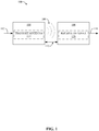
- Fig. 1 illustrates a wireless transmission or charging system 100, in accordance with various aspects described herein.
- transmitter 104 may be included as part of NFC device 310 ( Fig. 3 ). Specifically, for example, transmitter 104 may form or otherwise be part of transceiver 360 ( Fig. 3 ). Additionally, transmit antenna may form otherwise be part of antenna 370 ( Fig. 3 ).
- Input power 102 is provided to a transmitter 104 for generating a radiated inductive field 106 for providing energy transfer.
- a receiver 108 couples to the radiated inductive field 106 and generates an output power 110 for storage or consumption by a device (not shown) coupled to the output power 110.
- transmitter 104 and the receiver 108 are separated by a distance 112, which is also referred to herein as an operating volume (OV).
- OV operating volume
- transmitter 104 and receiver 108 are configured according to a mutual resonant relationship and when the resonant frequency of receiver 108 and the resonant frequency of transmitter 104 are within a threshold OV, transmission losses between the transmitter 104 and the receiver 108 are minimal (e.g., when the receiver 108 is located in the "near-field" of the radiated inductive field 106).
- Transmitter 104 further includes a transmit antenna 114 for transmitting energy and signals.
- a receiver 108 includes a receive antenna 118 for receiving signal and energy if needed.
- the transmit antenna 114 and receive antenna 118 can be sized according to applications and devices associated therewith. As stated, an efficient energy transfer can occur by coupling a large portion of the energy in the near-field of the transmitting antenna 114 to a receiving antenna 118 rather than propagating most of the energy in an electromagnetic wave to a far field. When in this near-field, a coupling mode may be developed between the transmit antenna 114 and the receive antenna 118. The area around the antennas 114 and 118 where this near-field coupling may occur is referred to herein as a coupling-mode region.
- transmitter 104 can detect such over-coupling with receiver 108 or related receive antenna 118, and can attempt to mitigate the condition by modifying one or more transmit and/or receive parameters at transmitter 104.
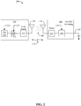
- Fig. 2 is a schematic diagram of an example near field wireless communication system 200.
- the transmitter 104 includes an oscillator 222, a power amplifier 224 and a filter and matching circuit 226.
- transmitter 104 may be included as part of NFC device 310 ( Fig. 3 ).
- transmitter 104 may form or otherwise be part of transceiver 360 ( Fig. 3 ).
- transmit antenna may form otherwise be part of antenna 370 ( Fig. 3 ).
- the oscillator 222 is configured to generate a signal at a desired frequency, which may be adjusted in response to adjustment signal 223.
- the oscillator signal may be amplified by the power amplifier 224 with an amplification amount responsive to control signal 225.
- the filter and matching circuit 226 may be included to filter out harmonics or other unwanted frequencies and match the impedance of the transmitter 104 to the transmit antenna 114.
- the receiver 108 may include a matching circuit 232 and a rectifier and switching circuit 234 to generate a DC power output to charge a battery 236 as shown in Fig. 2 or power a device coupled to the receiver (not shown), though it is to be appreciated that devices may each have batteries (e.g., in peer-to-peer communications) such that powering by magnetic field may not be needed.
- the matching circuit 232 may be included to match the impedance of the receiver 108 to the receive antenna 118.
- the receiver 108 and transmitter 104 may communicate on a separate communication channel 219 (e.g., Bluetooth, WiFi, zigbee, cellular, etc), in one example.
- communication network 300 may include an NFC device 310 and a remote NFC device 380, both of which may be configured to communicate using NFC.
- NFC device 310 may include transceiver 360 and antenna 370, each of which may be configured to facilitate communication with remote NFC device 380 using NFC.
- remote NFC device 380 may correspond to a remote device, card, or tag, connected wirelessly over the NFC radio interface to the NFC device 310.
- NFC device 310 may, via NFC controller 340, be configured to efficiently adjust an NFC mode based on receiving an NCI indication 334 specifying a screen state 338 of an associated user interface.
- Device host 320 may be configured to provide or otherwise transmit an NCI indication 334 including or specifying a screen state 338 of the device host 320 over the NFC controller interface (NCI) 330 to NFC controller 340.
- the screen state 338 may be an indicator that identifies or indicates one of a screen state ON, a screen state OFF or a screen state LOCK.
- the device host 320 may be or otherwise take the form of an execution environment responsible for the overall management of the NFC device 310 and any peripherals. This may include the management (e.g., initialization, configuration, power management, etc.) of the NFC controller 340.
- NCI 330 may be configured to facilitate communication at least between the device host 320 and the NFC controller 340.
- the NCI 330 may be the logical interface between device host 320 and NFC controller 340.
- NCI 330 may be configured to facilitate the transmission of the NCI indication 334 including or specifying the screen state 338 of an associated user interface from device host 320 to NFC controller 340.
- the screen state 338 may be different from a previous screen state of the device host 320 (e.g., change from screen state ON to screen state OFF).
- NFC controller 340 may be configured to receive the NCI indication 334 specifying screen state 338 of the device host 320 and adjust one or more NFC modes (e.g., peer-to-peer (P2P) mode 352, reader/writer (R/W) mode 354 and/or card emulation mode 356) based on the screen state 338 specified or included in the NCI indication 334.
- the NFC controller 340 may be the logical entity responsible for the transmission of data over the NFC radio interface.
- the NFC controller 340 may have a logical connection NCI 330 and thus to the device host 320, and may have connections to additional NFC execution environments (NFCEEs).
- NFCEEs additional NFC execution environments
- NFC controller 340 may include a receiver function, which may be hardware, such as a programmed processor module, or computer-executable code executable by a processor, or some combination thereof, that operates to receive the NCI indication 334 from NCI 330 for further processing by NFC controller 340.
- a receiver function which may be hardware, such as a programmed processor module, or computer-executable code executable by a processor, or some combination thereof, that operates to receive the NCI indication 334 from NCI 330 for further processing by NFC controller 340.
- NFC controller 340 may be configured to adjust an NFC mode based on a single NCI indication 334 specifying screen state 338 and independent of, or without any additional indications/commands received from device host 320.
- NFC controller 340 may include an adjusting function, which may be hardware, such as a programmed processor module, or computer-executable code executable by a processor, or some combination thereof, that operates to adjust an NFC mode based on a single NCI indication 334 specifying screen state 338 and independent of, or without any additional indications/commands received from device host 320.
- the single NCI indication 334 including the screen state 338 may be an unacknowledged type of command, e.g., where a response acknowledging receipt is not necessary.
- NFC controller 340 may be configured to maintain an RF discovery state before, during and/or after receiving the NCI indication 334 and adjusting the one or more NFC modes.
- NFC controller 340 may include a maintaining function, which may be hardware, such as a programmed processor module, or computer-executable code executable by a processor, or some combination thereof, that operates to maintain an RF discovery state before, during and/or after receiving the NCI indication 334 and adjusting the one or more NFC modes.
- NFC controller 340 may be configured to receive the NCI indication 334 including the screen state 338 and adjust one or more NFC modes based thereon while maintaining an RF discovery state (e.g., without transitioning into the RF idle state).
- NFC controller 340 may be configured to adjust, via the adjusting function, to one or more of a P2P mode 352, a R/W mode 354, or a card emulation mode 356 based on the screen state 338.
- each of the NFC modes may also correspond to an RF communication state such as polling and/or listening.
- the NFC device 310 may generate a carrier and probe ("poll") for other devices.
- the NFC device 310 may not generate a carrier, and rather listen for an RF field of another device.
- NFC controller 340 may be configured to adjust, via the adjusting function, to a polling state and a listening state corresponding to the screen state ON.
- the polling state includes one or both of P2P mode 352 and R/W mode 354.
- the listening state may include card emulation mode 356.
- NFC controller 340 may be configured to adjust, via the adjusting function, to a listening state corresponding to the screen state OFF and the screen state LOCK.
- the listening state may be activated.
- the listening state includes a card emulation mode 356.
- the card emulation mode 356 of screen state OFF and screen state LOCK may vary.
- card emulation mode 356 for screen state OFF may be activated in accordance with a UICC or an embedded secure element.
- card emulation mode 356 for screen state LOCK may be activated in accordance with a host secure element.
- NFC controller 340 may be configured to adjust the one or more NFC modes by adjusting one or both of a radio frequency discovery mode or a radio frequency configuration mode.
- NFC mode chart 400 presents the potential NFC modes that may be performed or otherwise triggered as active based at least in part on the screen state.
- an NFC controller e.g., NFC controller 340, Fig. 3
- may adjust an NFC mode upon or based on receiving a single NCI indication e.g., NCI indication 334, Fig. 1
- a screen state of device host e.g., device host 320, Fig. 1
- screen state ON may trigger an RF communication state of poll/polling, and thereby activate the peer-to-peer mode and reader/writer mode.
- screen state OFF and screen state LOCK may not trigger an RF communication state of poll/polling.
- screen state ON may also trigger an RF communication state of listen/listening, and thereby activate the peer-to-peer mode and/or card emulation mode.
- the card emulation mode may be activated in accordance with a host secure element, a UICC, or an embedded secure element.
- screen state OFF may trigger an RF communication state of listen/listening, and thereby activate the card emulation mode in accordance with a UICC or an embedded secure element.
- screen state LOCK may trigger an RF communication state of listen/listening, and thereby activate the card emulation mode in accordance with a host secure element, a UICC, or an embedded secure element.
- an NFC device such as NFC device 310 ( Fig. 3 ) may perform one aspect of a method 500 for adjusting one or more NFC modes based on an NCI indication. While, for purposes of simplicity of explanation, the method is shown and described as a series of acts, it is to be understood and appreciated that the method (and further methods related thereto) is/are not limited by the order of acts, as some acts may, in accordance with one or more aspects, occur in different orders and/or concurrently with other acts from that shown and described herein. For example, it is to be appreciated that a method could alternatively be represented as a series of interrelated states or events, such as in a state diagram. Moreover, not all illustrated acts may be required to implement a method in accordance with one or more features described herein.
- method 500 may receive, at an NFC controller, an NCI indication from a device host, wherein the NCI indication specifies a screen state of the device host.
- NFC device 310 may execute NFC controller 340 ( Fig. 3 ) to receive an NCI indication 334 ( Fig. 3 ) from a device host 320 ( Fig. 3 ).
- the NCI indication 334 may specify a screen state 338 ( Fig. 3 ) of the device host 320 ( Fig. 3 ).
- method 500 may adjust one or more NFC modes at the NFC controller based on the NCI indication.
- NFC device 310 may execute NFC controller 340 ( Fig. 3 ) to adjust one or more NFC modes at the NFC controller 340 ( Fig. 3 ) based on the NCI indication 334 ( Fig. 3 ).
- device host 320 may communicate with NFC controller 340 via a NFC communication interface (NCI), such as NCI 330 of Fig. 3 .
- NCI NFC communication interface
- the NCI 330 may be the logical interface between device host 320 and NFC controller 340.
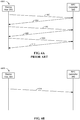
- the signaling scheme 600A corresponds to the instances where device host 320 is configured to transmit a plurality of indications/commands (e.g., signals 602, 606, and 610) instead of a single NCI indication 334 to the NFC controller 340.
- device host 320 may transmit signal 602 to NFC controller 340.
- signal 602 may be or may include an RF_DEACTIVATE_COMMAND signal.
- NFC controller 340 may transmit signal 604, which may be or may include an acknowledgment signal indicating that signal 602 was received.
- Device host 320 may then transmit signal 606, which may be or may include an RF_DISCOVER_CMD signal (e.g., with new discovery parameters).
- NFC controller 340 may transmit signal 608, which may be or may include an acknowledgment signal indicating that signal 606 was received.
- Device host 320 may then transmit signal 610, which may be or may include a CORE_SET_CONFIG_CMD signal (e.g., with new radio frequency configuration registries).
- NFC controller 340 may transmit signal 612, which may be or may include an acknowledgment signal indicating that signal 610 was received.
- a user equipment e.g., mobile device
- NFC device such as NFC device 310 of Fig.
- the foregoing deactivation, discovery and setting configuration commands/indications may be sent to the NFC controller 340, which may disrupt, delay, or otherwise prevent the NFC device 310 from performing listening and/or polling. Accordingly, use of the NFC device 310 during such period may result in a failed NFC operation.
- a conceptual diagram of a signaling scheme 600B between a device host, such as device host 320, and a NFC controller, such as NFC controller 340 in accordance with an aspect described herein is illustrated.
- device host 320 may communication with NFC controller 340 via a NFC communication interface (NCI), such as NCI 330 of Fig. 3 .
- NCI NFC communication interface
- the NCI 330 may be the logical interface between device host 320 and NFC controller 340.
- the signaling scheme 600B corresponds to the instances where device host 320 is configured to transmit a single NCI indication 334 to NFC controller 340.
- device host 320 may transmit signal 614 to NFC controller 340.
- NCI indication 334 may include a screen state, such as screen state 338, and NCI indication 334 may be independent of, or without any, additional indications/commands received from device host 320 in order to cause deactivation, discovery and setting configuration relating to changes in the ON or OFF state of the user equipment screen.
- the signal 614 may be configured to be an unacknowledged type of command, e.g., where a response acknowledging receipt is not necessary.
- NFC controller 340 may be configured to maintain an RF discovery state before, during and/or after receiving the signal 614 and adjusting the one or more NFC modes.
- NFC controller 340 may be configured to receive the signal 614 including the screen state and adjust one or more NFC modes based thereon while maintaining an RF discovery state (e.g., without transitioning into the RF idle state).
- NCI indication 334 only a single indication/command, e.g., NCI indication 334, is necessary to be transmitted from the device host 320 to NFC controller 340 in order to indicate the screen state of the NFC device and cause deactivation, discovery and setting configuration relating to changes in the ON or OFF state of the user equipment screen.
- Communication network 300 may include a NFC device 702 and a remote NFC device 704 that may be configured to communicate using NFC.
- NFC device 302 may include a NFC antenna coil 706 configured to facilitate NFC communications with remote NFC device 704, which may have a similar NFC coil 726.
- NFC device 702 may be the same as or similar to NFC device 310 ( Fig. 3 ).
- NFC device 702 may include device host 320 ( Fig. 3 ), NFC controller interface ( Fig. 3 ) and NFC controller 340 ( Fig. 3 ).
- remote NFC device 704 may be the same as or similar to remote NFC device 380 ( Fig. 3 ).
- NFC antenna coil 706 may generate an electromagnetic field in the area around the NFC antenna coil 706. The strength of the field may depend on the power source and the size and number of turns in NFC antenna coil 706. Further, impedance mismatches may cause a range of amplitude/phase changes dependant on size and inductance of NFC antenna coil 706 in the magnetic field 728.
- Capacitor 718 may be connected in parallel with the NFC antenna coil 706, where a transmitter component 712 and capacitors 718 may form an RLC oscillator establishing a resonant circuit with a frequency that corresponds to one or more transmission frequencies of the NFC device 702.
- the electromagnetic field can be treated as an alternating magnetic field 728.
- This region of close proximity is referred to as the near field region.
- the NFC device 702 and remote NFC device 704 may be linked by their mutual inductance, as in an air core transformer, with the primary coil being the NFC antenna coil 306 and the secondary coil being the antenna coil 726 of the remote NFC device 704.
- the alternating magnetic field 728 penetrates the antenna coil 726 of the remote NFC device 304 when it is in the near field region, inducing an alternating current in the antenna coil 726 of the remote NFC device 704.
- the NFC antenna coil 706, capacitors 720, optional energy harvester (EH) 716 and a receiver component 714 may form an RLC oscillator establishing a resonant circuit over which modulation of signal by remote NFC device 704 can be detected.
- NFC device 702 may apply a variable load resistance to the NFC antenna coil 706, thereby modulating magnetic field 728, to send a transmitted signal to transfer data to the remote NFC device 704.
- Fig. 8 illustrates an example architecture of communications device 800.
- Communications device may include NFC device 310, 702, remote NFC device 380, 704, etc., and may thus include components thereof and/or perform the associated functions described above.
- communications device 800 includes receiver 802 that receives a signal from, for instance, a receive antenna (not shown), performs typical actions on (e.g., filters, amplifies, downconverts, etc.) the received signal, and digitizes the conditioned signal to obtain samples.
- Receiver 802 can include a demodulator 804 that can demodulate received symbols and provide them to processor 806 for channel estimation.
- Processor 806 can be a processor dedicated to analyzing information received by receiver 802 and/or generating information for transmission by transmitter 820, a processor that controls one or more components of communications device 800, and/or a processor that both analyzes information received by receiver 802, generates information for transmission by transmitter 820, and controls one or more components of communications device 800. Further, signals may be prepared for transmission by transmitter 820 through modulator 818 which may modulate the signals processed by processor 806.
- Communications device 800 can additionally include memory 808 that is operatively coupled to processor 806 and that can store data to be transmitted, received data, information related to available channels, TCP flows, data associated with analyzed signal and/or interference strength, information related to an assigned channel, power, rate, or the like, and any other suitable information for estimating a channel and communicating via the channel.
- memory 808 that is operatively coupled to processor 806 and that can store data to be transmitted, received data, information related to available channels, TCP flows, data associated with analyzed signal and/or interference strength, information related to an assigned channel, power, rate, or the like, and any other suitable information for estimating a channel and communicating via the channel.
- transmitter 820 can generate a transmission signal for a transmitted carrier at a transmit circuit, and receiver 802 can receive a received carrier at a receive circuit. As described, transmitter 820 can be looped back to receiver 802 so the receiver 802 can receive the unmodulated carrier.
- Processor 806 can include or can implement over-coupling detecting component 850 for detecting an over-coupling condition with another communications device based on comparing the received unmodulated carrier to the transmission signal generated by transmitter 820. As described, where the over-coupling condition occurs, this can be detected based on a threshold difference between a phase, amplitude, DC level, or other metric of the received carrier and transmission signal.
- processor 806 can include or can implement Tx/Rx parameter component 852 for modifying a transmit or receive metric of transmitter 820 or receiver 802, as described, to mitigate the over-coupling condition.
- Processor 806 may also include or implement filter bypassing component 854 for bypassing one or more filters or other signal processing components of communications device 800 that may exist between the receiver 802 and over-coupling detecting component 850 to facilitate detection of over-coupling in the signal unaltered by the components.
- data store e.g., memory 808
- nonvolatile memory can include read only memory (ROM), programmable ROM (PROM), electrically programmable ROM (EPROM), electrically erasable PROM (EEPROM), or flash memory.
- Volatile memory can include random access memory (RAM), which acts as external cache memory.
- RAM is available in many forms such as synchronous RAM (SRAM), dynamic RAM (DRAM), synchronous DRAM (SDRAM), double data rate SDRAM (DDR SDRAM), enhanced SDRAM (ESDRAM), Synchlink DRAM (SLDRAM), and direct Rambus RAM (DRRAM).
- SRAM synchronous RAM
- DRAM dynamic RAM
- SDRAM synchronous DRAM
- DDR SDRAM double data rate SDRAM
- ESDRAM enhanced SDRAM
- SLDRAM Synchlink DRAM
- DRRAM direct Rambus RAM
- Memory 808 of the subject systems and methods may comprise, without being limited to, these and any other suitable types of memory.
- memory 808 can include instructions for performing the functions of the various components described herein.
- Communications device 800 may include NFC controller interface (NCI) 330.
- NCI 330 may be configured to enable communications between a NFC controller 340 and device host 320.
- communications device 800 may include user interface 840.
- User interface 840 may include input mechanisms 842 for generating inputs into communications device 800, and output mechanism 844 for generating information for consumption by the user of the communications device 800.
- input mechanism 842 may include a mechanism such as a key or keyboard, a mouse, a touch-screen display, a microphone, etc.
- output mechanism 844 may include a display, an audio speaker, a haptic feedback mechanism, etc.
- the output mechanism 844 may include a display configured to present media content that is in image or video format or an audio speaker to present media content that is in an audio format.
- a component may be, but is not limited to being, a process running on a processor, a processor, an object, an executable, a thread of execution, a program, and/or a computer.
- an application running on a computing device and the computing device can be a component.
- One or more components can reside within a process and/or thread of execution and a component may be localized on one computer and/or distributed between two or more computers.
- these components can execute from various computer readable media having various data structures stored thereon.
- the components may communicate by way of local and/or remote processes such as in accordance with a signal having one or more data packets, such as data from one component interacting with another component in a local system, distributed system, and/or across a network such as the Internet with other systems by way of the signal.
- a terminal can be a wired terminal or a wireless terminal.
- a terminal can also be called a system, device, subscriber unit, subscriber station, mobile station, mobile, mobile device, remote station, mobile equipment (ME), remote terminal, access terminal, user terminal, terminal, communication device, user agent, user device, or user equipment (UE).
- a wireless terminal may be a cellular telephone, a satellite phone, a cordless telephone, a Session Initiation Protocol (SIP) phone, a wireless local loop (WLL) station, a personal digital assistant (PDA), a handheld device having wireless connection capability, a computing device, or other processing devices connected to a wireless modem.
- SIP Session Initiation Protocol
- WLL wireless local loop
- PDA personal digital assistant
- a base station may be utilized for communicating with wireless terminal(s) and may also be referred to as an access point, a Node B, or some other terminology.
- the term "or” is intended to mean an inclusive “or” rather than an exclusive “or.” That is, unless specified otherwise, or clear from the context, the phrase “X employs A or B” is intended to mean any of the natural inclusive permutations. That is, the phrase “X employs A or B” is satisfied by any of the following instances: X employs A; X employs B; or X employs both A and B.
- the articles “a” and “an” as used in this application and the appended claims should generally be construed to mean “one or more” unless specified otherwise or clear from the context to be directed to a singular form.
- a CDMA system may implement a radio technology such as Universal Terrestrial Radio Access (UTRA), cdma2000, etc.
- UTRA includes Wideband-CDMA (W-CDMA) and other variants of CDMA.
- W-CDMA Wideband-CDMA
- cdma2000 covers IS-2000, IS-95 and IS-856 standards.
- GSM Global System for Mobile Communications
- An OFDMA system may implement a radio technology such as Evolved UTRA (E-UTRA), Ultra Mobile Broadband (UMB), IEEE 802.11 (Wi-Fi), IEEE 802.16 (WiMAX), IEEE 802.20, Flash-OFDMA, etc.
- E-UTRA Evolved UTRA
- UMB Ultra Mobile Broadband
- IEEE 802.11 Wi-Fi
- WiMAX IEEE 802.16
- Flash-OFDMA Flash-OFDMA
- UTRA and E-UTRA are part of Universal Mobile Telecommunication System (UMTS).
- UMTS Universal Mobile Telecommunication System
- 3GPP Long Term Evolution (LTE) is a release of UMTS that uses E-UTRA, which employs OFDMA on the downlink and SC-FDMA on the uplink.
- UTRA, E-UTRA, UMTS, LTE and GSM are described in documents from an organization named "3rd Generation Partnership Project" (3GPP).
- wireless communication systems may additionally include peer-to-peer (e.g., mobile-to-mobile) ad hoc network systems often using unpaired unlicensed spectrums, 802.xx wireless LAN, BLUETOOTH, near-field communications (NFC-A, NFC-B, NFC,-f, etc.), and any other short- or long- range, wireless communication techniques.
- peer-to-peer e.g., mobile-to-mobile
- ad hoc network systems often using unpaired unlicensed spectrums
- 802.xx wireless LAN e.g., 802.xx wireless LAN, BLUETOOTH, near-field communications (NFC-A, NFC-B, NFC,-f, etc.)
- NFC-A, NFC-B, NFC,-f, etc. near-field communications
- DSP digital signal processor
- ASIC application specific integrated circuit
- FPGA field programmable gate array
- a general-purpose processor may be a microprocessor, but, in the alternative, the processor may be any conventional processor, controller, microcontroller, or state machine.
- a processor may also be implemented as a combination of computing devices, e.g., a combination of a DSP and a microprocessor, a plurality of microprocessors, one or more microprocessors in conjunction with a DSP core, or any other such configuration. Additionally, at least one processor may comprise one or more modules configured to perform one or more of the steps and/or actions described above.
- a software module may reside in RAM memory, flash memory, ROM memory, EPROM memory, EEPROM memory, registers, a hard disk, a removable disk, a CD-ROM, or any other form of storage medium known in the art.
- An example storage medium may be coupled to the processor, such that the processor can read information from, and write information to, the storage medium.
- the storage medium may be integral to the processor.
- the processor and the storage medium may reside in an ASIC. Additionally, the ASIC may reside in a user terminal.
- processor and the storage medium may reside as discrete components in a user terminal. Additionally, in some aspects, the steps and/or actions of a method or algorithm may reside as one or any combination or set of codes and/or instructions on a machine readable medium and/or computer readable medium, which may be incorporated into a computer program product.
- the functions described may be implemented in hardware, software, firmware, or any combination thereof. If implemented in software, the functions may be stored or transmitted as one or more instructions or code on a computer-readable medium.
- Computer-readable media includes both computer storage media and communication media including any medium that facilitates transfer of a computer program from one place to another.
- a storage medium may be any available media that can be accessed by a computer.
- such computer-readable media can comprise RAM, ROM, EEPROM, CD-ROM or other optical disk storage, magnetic disk storage or other magnetic storage devices, or any other medium that can be used to carry or store desired program code in the form of instructions or data structures and that can be accessed by a computer.
- any connection may be termed a computer-readable medium.
- Disk and disc includes compact disc (CD), laser disc, optical disc, digital versatile disc (DVD), floppy disk and blu-ray disc where disks usually reproduce data magnetically, while discs usually reproduce data optically with lasers. Combinations of the above should also be included within the scope of computer-readable media.
Landscapes
- Engineering & Computer Science (AREA)
- Computer Networks & Wireless Communication (AREA)
- Physics & Mathematics (AREA)
- Health & Medical Sciences (AREA)
- Toxicology (AREA)
- General Physics & Mathematics (AREA)
- Theoretical Computer Science (AREA)
- Signal Processing (AREA)
- Computer Vision & Pattern Recognition (AREA)
- Electromagnetism (AREA)
- General Health & Medical Sciences (AREA)
- Artificial Intelligence (AREA)
- Computer Hardware Design (AREA)
- Microelectronics & Electronic Packaging (AREA)
- Computer Security & Cryptography (AREA)
- Databases & Information Systems (AREA)
- Mobile Radio Communication Systems (AREA)
- Telephone Function (AREA)
- Near-Field Transmission Systems (AREA)
Description
- The disclosed aspects relate generally to communications between and/or within devices and specifically to improving near field communication mode adjustments.
- Advances in technology have resulted in smaller and more powerful personal computing devices. For example, there currently exist a variety of portable personal computing devices, including wireless computing devices, such as portable wireless telephones, personal digital assistants (PDAs) and paging devices that are each small, lightweight, and can be easily carried by users. More specifically, the portable wireless telephones, for example, further include cellular telephones that communicate voice and data packets over wireless networks. Many such cellular telephones are manufactured with ever increasing computing capabilities, and as such, are becoming tantamount to small personal computers and hand-held PDAs. Further, such devices are enabling communications using a variety of frequencies and applicable coverage areas, such as cellular communications, wireless local area network (WLAN) communications, near field communication (NFC), etc.
- In some NFC devices, ineffective and/or inefficient operation or utilization of communication resources, particularly related to NFC mode adjustments, may lead to degradations in communication between an NFC device and a device in communication therewith. Even more, the foregoing ineffective and/or inefficient operation may inhibit a user equipment equipped with an NFC device from achieving higher communication quality. Thus, improvements in NFC mode adjustments may be desired.
- Document
EP 2 621 223 A1 relates to electronic devices and related methods that use near-field communication (NFC). A mobile wireless communications device may include a near field communication (NFC) device operable in a first NFC mode or a second NFC mode, wherein the second NFC mode has a lower power consumption level associated therewith than the first NFC mode. The mobile wireless communications device may further include a processor coupled with the NFC device and capable of detecting a field change via the NFC device when the NFC device is in the second NFC mode, determining a condition of the mobile communications device, and switching the NFC device from the second NFC mode to the first NFC mode based upon the field change and the condition. - Document
JP 2013 255039 A - The following presents a summary of one or more aspects to provide a basic understanding of such aspects. This summary is not an extensive overview of all contemplated aspects, and is not intended to identify key or critical elements of all aspects nor delineate the scope of any or all aspects. Its purpose is to present some concepts of one or more aspects form as a prelude to the more detailed description presented later.
- In an aspect, a method of near field communication (NFC) relates to adjusting an NFC mode based on a screen state indication. The method includes receiving, at an NFC controller, an NFC controller interface (NCI) indication from a device host, wherein the NCI indication specifies a screen state of the device host, and adjusting one or more NFC modes at the NFC controller based on the NCI indication.
- In another aspect, a computer-readable medium storing computer executable code for near field communication (NFC) relates to adjusting an NFC mode based on a screen state indication. The computer-readable medium includes code executable to receive, at an NFC controller, an NFC controller interface (NCI) indication from a device host, wherein the NCI indication specifies a screen state of the device host, and code executable to adjust one or more NFC modes at the NFC controller based on the NCI indication.
- In a further aspect, an apparatus for near field communication (NFC) relates to adjusting an NFC mode based on a screen state indication. The apparatus includes means for receiving, at an NFC controller, an NFC controller interface (NCI) indication from a device host, wherein the NCI indication specifies a screen state of the device host, and means for adjusting one or more NFC modes at the NFC controller based on the NCI indication.
- In yet another aspect, an apparatus relates to adjusting an NFC mode based on a screen state indication. The apparatus includes an NFC controller configured to receive an NFC controller interface (NCI) indication from a device host, wherein the NCI indication specifies a screen state of the device host, and configured to adjust one or more NFC modes at the NFC controller based on the NCI indication.
- To accomplish the foregoing and related ends, the one or more aspects comprise features hereinafter fully described and particularly pointed out in the claims. The following description and the annexed drawings set forth in detail certain illustrative features of the one or more aspects. These features are indicative, however, of but a few of the various ways in which the principles of various aspects may be employed, and this description is intended to include all such aspects that fall within the scope of the appended claims.
- To facilitate a fuller understanding of the present disclosure, reference is now made to the accompanying drawings, in which like elements are referenced with like numerals, and where dashed lines may indicate optional components or actions. These drawings should not be construed as limiting the present disclosure, but are intended to be illustrative only, wherein:
-
Fig. 1 is a block diagram of a wireless communication system in accordance with an aspect of the present disclosure. -
Fig. 2 is a schematic diagram of a wireless communication system in accordance with an aspect of the present disclosure. -
Fig. 3 is a block diagram of an NFC environment in accordance with an aspect of the present disclosure. -
Fig. 4 is a conceptual diagram of an NFC mode chart in accordance with an aspect of the present disclosure. -
Fig. 5 is a flowchart describing an aspect of adjusting an NFC mode based on a screen state indication; -
Fig. 6A is a conceptual diagram of an NFC mode signaling in accordance with an aspect of a prior disclosure. -
Fig. 6B is a conceptual diagram of an NFC mode signaling in accordance with an aspect of the present disclosure. -
Fig. 7 is a block diagram of another NFC environment in accordance with an aspect of the present disclosure; -
Fig. 8 is a functional block diagram example architecture of a communications device in accordance with an aspect of the present disclosure. - The detailed description set forth below, in connection with the appended drawings, is intended as a description of various configurations and is not intended to represent the only configurations in which the concepts described herein may be practiced. The detailed description includes specific details for the purpose of providing a thorough understanding of the various concepts. However, it will be apparent to those skilled in the art that these concepts may be practiced without these specific details. In some instances, well-known components are shown in block diagram form in order to avoid obscuring such concepts. In an aspect, the term "component" as used herein may be one of the parts that make up a system, may be hardware or software, and may be divided into other components.
- The present aspects generally relate to adjusting one or more NFC modes of an NFC device based on an indication specifying a screen state. Specifically, an NFC device may operate according to one or more NFC modes. A NFC device may operate in a reader/writer mode, a peer-to-peer mode, and a card emulation mode. In the reader/writer mode, the NFC device emits an electromagnetic field that powers a passive transponder/tag. Operating in this mode, the NFC device may read and alter data stored in NFC compliant passive (e.g., without battery) transponders/tags. Such tags may permit the retrieval of additional information by reading the tag with the NFC device. The peer-to-peer mode (e.g., ISO 18092) may permit two NFC devices to establish a bidirectional connection to exchange data. In the card emulation mode, an NFC device may act as or perform functions similar to a smart card (e.g., ISO 14443). The emulated smart card may then be accessed by an external NFC reader, such as, but not limited to, an NFC point-of-sale terminal.
- Specifically, in an aspect, an NFC device may include a card emulation mode and a peer-to-peer mode as two example modes. The peer-to-peer mode may be implemented when a device host is present. Further, the card emulation mode may be implemented with or without the presence of the device host, yet may operate in conjunction with a secure element connected to an NFC controller of the NFC device. In an aspect, for example, the secure element may include or otherwise take the form of, but is not limited to, a universal integrated circuit card (UICC) or an embedded secure element.
- In aspects where an NFC device is integrated with or otherwise included as part of a user equipment (e.g., mobile device), the peer-to-peer mode may not be available when the device host is not present or not in operation. For example, in an aspect, the device host may include a user interface (e.g., a display or screen or display screen) of the user equipment, which may not be active or available (e.g., alternatively referred to as a screen OFF state). When changing the screen states (e.g., screen ON state to/from screen OFF state), the peer-to-peer mode may be enabled or disabled, respectively. As such, the device host may notify each change in screen state to the NFC Controller via, for example, an NFC controller interface.
- The NFC controller interface may support the changes in screen state by providing or otherwise communicating a number or sequence of indications/commands corresponding to a change in screen state. For instance, the device host may send an RF_DEACTIVATE_COMMAND followed by an RF_DISCOVER_CMD (e.g., with new discovery parameters) and CORE_SET_CONFIG_CMD (e.g., with new radio frequency configuration registries). As such, in a user equipment (e.g., mobile device) including an NFC device, each time the user equipment screen changes from ON/OFF, the foregoing deactivation, discovery and setting configuration commands/indications may be sent to the NFC controller, which may disrupt, delay, or otherwise prevent the NFC device from performing listening and/or polling. Accordingly, use of the NFC device during such period may result in a failed NFC operation.
- As such, the present aspects may provide an efficient and effective solution, as compared to current solutions, to adjust one or more NFC modes of an NFC device (e.g., at or via an NFC controller) based on a single NFC controller interface (NCI) indication that includes an identification of a screen state of the device host. For example, an NFC controller may determine one or more NFC modes to perform or execute based on a single NCI indication/command including a screen state of the device host. Specifically, the device host may send an NCI indication/command notifying/signifying the NFC controller of a new screen state. The new screen state may indicate to or trigger the NFC Controller to adjust the RF Discovery Parameters and/or the related RF configuration settings.
- In such aspect, a single NCI indication/command may replace or be used in lieu of a number or sequence (e.g., three in some cases) NCI indications/commands. Moreover, the single NCI indication/command including the screen state may be configured to be an unacknowledged type of command, e.g., where a response acknowledging receipt is not necessary. In contrast, the existing number of sequence of NCI commands require an acknowledgement. As such, the present aspects may decrease the NCI traffic (e.g., data transmission along the NCI) and may reduce a time delay for processing the screen changes at the NFC controller. Further, the time during which the NFC device may be available or active may increase, thereby decreasing the communication failure rate/probability. Accordingly, the present aspects provide enhanced NFC mode adjustments.
- Aspects of the present disclosure are depicted with reference to one or more components and one or more methods that may perform the actions or functions described herein. In an aspect, the term "component" as used herein may be one of the parts that make up a system, may be hardware or software or some combination thereof, and may be divided into other components. Although the operations described herein are presented in a particular order and/or as being performed by an example component, it should be understood that the ordering of the actions and the components performing the actions may be varied, depending on the implementation. Moreover, it should be understood that the following actions or functions may be performed by a specially-programmed processor, a processor executing specially-programmed software or computer-readable media, or by any other combination of a hardware component and/or a software component capable of performing the described actions or functions.
-
Fig. 1 illustrates a wireless transmission or chargingsystem 100, in accordance with various aspects described herein. In some aspects,transmitter 104 may be included as part of NFC device 310 (Fig. 3 ). Specifically, for example,transmitter 104 may form or otherwise be part of transceiver 360 (Fig. 3 ). Additionally, transmit antenna may form otherwise be part of antenna 370 (Fig. 3 ).Input power 102 is provided to atransmitter 104 for generating a radiatedinductive field 106 for providing energy transfer. Areceiver 108 couples to the radiatedinductive field 106 and generates anoutput power 110 for storage or consumption by a device (not shown) coupled to theoutput power 110. Both thetransmitter 104 and thereceiver 108 are separated by adistance 112, which is also referred to herein as an operating volume (OV). In one example,transmitter 104 andreceiver 108 are configured according to a mutual resonant relationship and when the resonant frequency ofreceiver 108 and the resonant frequency oftransmitter 104 are within a threshold OV, transmission losses between thetransmitter 104 and thereceiver 108 are minimal (e.g., when thereceiver 108 is located in the "near-field" of the radiated inductive field 106). -
Transmitter 104 further includes a transmitantenna 114 for transmitting energy and signals. Areceiver 108 includes a receiveantenna 118 for receiving signal and energy if needed. The transmitantenna 114 and receiveantenna 118 can be sized according to applications and devices associated therewith. As stated, an efficient energy transfer can occur by coupling a large portion of the energy in the near-field of the transmittingantenna 114 to a receivingantenna 118 rather than propagating most of the energy in an electromagnetic wave to a far field. When in this near-field, a coupling mode may be developed between the transmitantenna 114 and the receiveantenna 118. The area around theantennas - In some configurations, where the
transmitter 104 andreceiver 108 are in very close proximity, matching networks (not shown) related to theantennas transmitter 104 andreceiver 108, and thus communications betweentransmitter 104 andreceiver 108 may break down. This condition is referred to herein as over-coupling. In such examples, as described further herein,transmitter 104 can detect such over-coupling withreceiver 108 or related receiveantenna 118, and can attempt to mitigate the condition by modifying one or more transmit and/or receive parameters attransmitter 104. -
Fig. 2 is a schematic diagram of an example near fieldwireless communication system 200. Thetransmitter 104 includes anoscillator 222, apower amplifier 224 and a filter and matchingcircuit 226. In some aspects,transmitter 104 may be included as part of NFC device 310 (Fig. 3 ). Specifically, for example,transmitter 104 may form or otherwise be part of transceiver 360 (Fig. 3 ). Additionally, transmit antenna may form otherwise be part of antenna 370 (Fig. 3 ). Theoscillator 222 is configured to generate a signal at a desired frequency, which may be adjusted in response toadjustment signal 223. The oscillator signal may be amplified by thepower amplifier 224 with an amplification amount responsive to controlsignal 225. The filter and matchingcircuit 226 may be included to filter out harmonics or other unwanted frequencies and match the impedance of thetransmitter 104 to the transmitantenna 114. - The
receiver 108 may include amatching circuit 232 and a rectifier and switchingcircuit 234 to generate a DC power output to charge abattery 236 as shown inFig. 2 or power a device coupled to the receiver (not shown), though it is to be appreciated that devices may each have batteries (e.g., in peer-to-peer communications) such that powering by magnetic field may not be needed. Thematching circuit 232 may be included to match the impedance of thereceiver 108 to the receiveantenna 118. Thereceiver 108 andtransmitter 104 may communicate on a separate communication channel 219 (e.g., Bluetooth, WiFi, zigbee, cellular, etc), in one example. - Referring to
Fig. 3 , in an aspect,communication network 300 may include anNFC device 310 and aremote NFC device 380, both of which may be configured to communicate using NFC.NFC device 310 may includetransceiver 360 andantenna 370, each of which may be configured to facilitate communication withremote NFC device 380 using NFC. For example,remote NFC device 380 may correspond to a remote device, card, or tag, connected wirelessly over the NFC radio interface to theNFC device 310.NFC device 310 may, viaNFC controller 340, be configured to efficiently adjust an NFC mode based on receiving anNCI indication 334 specifying ascreen state 338 of an associated user interface. -
Device host 320 may be configured to provide or otherwise transmit anNCI indication 334 including or specifying ascreen state 338 of thedevice host 320 over the NFC controller interface (NCI) 330 toNFC controller 340. In some aspects, thescreen state 338 may be an indicator that identifies or indicates one of a screen state ON, a screen state OFF or a screen state LOCK. Further, thedevice host 320 may be or otherwise take the form of an execution environment responsible for the overall management of theNFC device 310 and any peripherals. This may include the management (e.g., initialization, configuration, power management, etc.) of theNFC controller 340. -
NCI 330 may be configured to facilitate communication at least between thedevice host 320 and theNFC controller 340. For example, theNCI 330 may be the logical interface betweendevice host 320 andNFC controller 340. Specifically,NCI 330 may be configured to facilitate the transmission of theNCI indication 334 including or specifying thescreen state 338 of an associated user interface fromdevice host 320 toNFC controller 340. In some aspects, thescreen state 338 may be different from a previous screen state of the device host 320 (e.g., change from screen state ON to screen state OFF). -
NFC controller 340 may be configured to receive theNCI indication 334 specifyingscreen state 338 of thedevice host 320 and adjust one or more NFC modes (e.g., peer-to-peer (P2P)mode 352, reader/writer (R/W)mode 354 and/or card emulation mode 356) based on thescreen state 338 specified or included in theNCI indication 334. For example, theNFC controller 340 may be the logical entity responsible for the transmission of data over the NFC radio interface. TheNFC controller 340 may have alogical connection NCI 330 and thus to thedevice host 320, and may have connections to additional NFC execution environments (NFCEEs). Further,NFC controller 340 may include a receiver function, which may be hardware, such as a programmed processor module, or computer-executable code executable by a processor, or some combination thereof, that operates to receive theNCI indication 334 fromNCI 330 for further processing byNFC controller 340. - Hence,
NFC controller 340 may be configured to adjust an NFC mode based on asingle NCI indication 334 specifyingscreen state 338 and independent of, or without any additional indications/commands received fromdevice host 320. For example,NFC controller 340 may include an adjusting function, which may be hardware, such as a programmed processor module, or computer-executable code executable by a processor, or some combination thereof, that operates to adjust an NFC mode based on asingle NCI indication 334 specifyingscreen state 338 and independent of, or without any additional indications/commands received fromdevice host 320. Moreover, thesingle NCI indication 334 including thescreen state 338 may be an unacknowledged type of command, e.g., where a response acknowledging receipt is not necessary. Additionally,NFC controller 340 may be configured to maintain an RF discovery state before, during and/or after receiving theNCI indication 334 and adjusting the one or more NFC modes. For example,NFC controller 340 may include a maintaining function, which may be hardware, such as a programmed processor module, or computer-executable code executable by a processor, or some combination thereof, that operates to maintain an RF discovery state before, during and/or after receiving theNCI indication 334 and adjusting the one or more NFC modes. That is, as opposed to transitioning to and from idle state after receiving an NCI indication 334 (e.g., resulting in an RF deactivation),NFC controller 340 may be configured to receive theNCI indication 334 including thescreen state 338 and adjust one or more NFC modes based thereon while maintaining an RF discovery state (e.g., without transitioning into the RF idle state). - For example,
NFC controller 340 may be configured to adjust, via the adjusting function, to one or more of aP2P mode 352, a R/W mode 354, or acard emulation mode 356 based on thescreen state 338. Further, each of the NFC modes may also correspond to an RF communication state such as polling and/or listening. For example, during the polling state/mode, theNFC device 310 may generate a carrier and probe ("poll") for other devices. In other aspects, during the listening state/mode, theNFC device 310 may not generate a carrier, and rather listen for an RF field of another device. - Specifically, for instance,
NFC controller 340 may be configured to adjust, via the adjusting function, to a polling state and a listening state corresponding to the screen state ON. In other words, whenNCI indication 334 includes ascreen state 338 specifying a screen state ON, the polling state and the listening state may be activated. In some aspects, the polling state includes one or both ofP2P mode 352 and R/W mode 354. Additionally, the listening state may includecard emulation mode 356. - Further, for example,
NFC controller 340 may be configured to adjust, via the adjusting function, to a listening state corresponding to the screen state OFF and the screen state LOCK. In other words, whenNCI indication 334 includes ascreen state 338 of either screen state OFF or screen state LOCK, the listening state may be activated. In some aspects, the listening state includes acard emulation mode 356. However, thecard emulation mode 356 of screen state OFF and screen state LOCK may vary. For instance,card emulation mode 356 for screen state OFF may be activated in accordance with a UICC or an embedded secure element. On the other hand,card emulation mode 356 for screen state LOCK may be activated in accordance with a host secure element. In other aspects,NFC controller 340 may be configured to adjust the one or more NFC modes by adjusting one or both of a radio frequency discovery mode or a radio frequency configuration mode. - Referring to
Fig. 4 , a conceptual diagram of an NFC mode chart 400 in accordance with an aspect described herein is illustrated. NFC mode chart 400 presents the potential NFC modes that may be performed or otherwise triggered as active based at least in part on the screen state. In other words, an NFC controller (e.g.,NFC controller 340,Fig. 3 ) may adjust an NFC mode upon or based on receiving a single NCI indication (e.g.,NCI indication 334,Fig. 1 ) specifying a screen state of device host (e.g.,device host 320,Fig. 1 ). - In an aspect, according to NFC mode chart 400, screen state ON may trigger an RF communication state of poll/polling, and thereby activate the peer-to-peer mode and reader/writer mode. However, screen state OFF and screen state LOCK may not trigger an RF communication state of poll/polling. Further, screen state ON may also trigger an RF communication state of listen/listening, and thereby activate the peer-to-peer mode and/or card emulation mode. In such aspect, the card emulation mode may be activated in accordance with a host secure element, a UICC, or an embedded secure element.
- Additionally, screen state OFF may trigger an RF communication state of listen/listening, and thereby activate the card emulation mode in accordance with a UICC or an embedded secure element. Similarly, screen state LOCK may trigger an RF communication state of listen/listening, and thereby activate the card emulation mode in accordance with a host secure element, a UICC, or an embedded secure element.
- Referring to
Fig. 5 , in an operational aspect, an NFC device such as NFC device 310 (Fig. 3 ) may perform one aspect of amethod 500 for adjusting one or more NFC modes based on an NCI indication. While, for purposes of simplicity of explanation, the method is shown and described as a series of acts, it is to be understood and appreciated that the method (and further methods related thereto) is/are not limited by the order of acts, as some acts may, in accordance with one or more aspects, occur in different orders and/or concurrently with other acts from that shown and described herein. For example, it is to be appreciated that a method could alternatively be represented as a series of interrelated states or events, such as in a state diagram. Moreover, not all illustrated acts may be required to implement a method in accordance with one or more features described herein. - In an aspect, at
block 510,method 500 may receive, at an NFC controller, an NCI indication from a device host, wherein the NCI indication specifies a screen state of the device host. For example, as described herein, NFC device 310 (Fig. 3 ) may execute NFC controller 340 (Fig. 3 ) to receive an NCI indication 334 (Fig. 3 ) from a device host 320 (Fig. 3 ). In some aspects, the NCI indication 334 (Fig. 3 ) may specify a screen state 338 (Fig. 3 ) of the device host 320 (Fig. 3 ). - At
block 520,method 500 may adjust one or more NFC modes at the NFC controller based on the NCI indication. For instance, as described herein, NFC device 310 (Fig. 3 ) may execute NFC controller 340 (Fig. 3 ) to adjust one or more NFC modes at the NFC controller 340 (Fig. 3 ) based on the NCI indication 334 (Fig. 3 ). - Referring to
Figs. 6A , a conceptual diagram of aprior signaling scheme 600A between a device host, such asdevice host 320, and a NFC controller, such asNFC controller 340. In certain aspects,device host 320 may communicate withNFC controller 340 via a NFC communication interface (NCI), such asNCI 330 ofFig. 3 . For example, theNCI 330 may be the logical interface betweendevice host 320 andNFC controller 340. Thesignaling scheme 600A corresponds to the instances wheredevice host 320 is configured to transmit a plurality of indications/commands (e.g., signals 602, 606, and 610) instead of asingle NCI indication 334 to theNFC controller 340. For instance,device host 320 may transmit signal 602 toNFC controller 340. In an aspect, for example, signal 602 may be or may include an RF_DEACTIVATE_COMMAND signal. In response to signal 602,NFC controller 340 may transmit signal 604, which may be or may include an acknowledgment signal indicating that signal 602 was received.Device host 320 may then transmit signal 606, which may be or may include an RF_DISCOVER_CMD signal (e.g., with new discovery parameters). In response to signal 606,NFC controller 340 may transmit signal 608, which may be or may include an acknowledgment signal indicating that signal 606 was received.Device host 320 may then transmitsignal 610, which may be or may include a CORE_SET_CONFIG_CMD signal (e.g., with new radio frequency configuration registries). In response to signal 610,NFC controller 340 may transmit signal 612, which may be or may include an acknowledgment signal indicating thatsignal 610 was received. As such, in a user equipment (e.g., mobile device) including an NFC device, such asNFC device 310 ofFig. 3 , each time the user equipment screen changes between ON and OFF, the foregoing deactivation, discovery and setting configuration commands/indications, e.g., signal 602, signal 606, and signal 610, may be sent to theNFC controller 340, which may disrupt, delay, or otherwise prevent theNFC device 310 from performing listening and/or polling. Accordingly, use of theNFC device 310 during such period may result in a failed NFC operation. - Referring to
Figs. 6B , a conceptual diagram of asignaling scheme 600B between a device host, such asdevice host 320, and a NFC controller, such asNFC controller 340 in accordance with an aspect described herein is illustrated. In certain aspects,device host 320 may communication withNFC controller 340 via a NFC communication interface (NCI), such asNCI 330 ofFig. 3 . For example, theNCI 330 may be the logical interface betweendevice host 320 andNFC controller 340. Thesignaling scheme 600B corresponds to the instances wheredevice host 320 is configured to transmit asingle NCI indication 334 toNFC controller 340. For instance,device host 320 may transmit signal 614 toNFC controller 340.Signal 614, which may be or may include an NFC indication, such asNCI indication 334 ofFig. 3 . In some instances,NCI indication 334 may include a screen state, such asscreen state 338, andNCI indication 334 may be independent of, or without any, additional indications/commands received fromdevice host 320 in order to cause deactivation, discovery and setting configuration relating to changes in the ON or OFF state of the user equipment screen. Moreover, thesignal 614 may be configured to be an unacknowledged type of command, e.g., where a response acknowledging receipt is not necessary. Additionally,NFC controller 340 may be configured to maintain an RF discovery state before, during and/or after receiving thesignal 614 and adjusting the one or more NFC modes. That is, as opposed to transitioning to and from idle state after receiving an signal 614 (e.g., resulting in an RF deactivation),NFC controller 340 may be configured to receive thesignal 614 including the screen state and adjust one or more NFC modes based thereon while maintaining an RF discovery state (e.g., without transitioning into the RF idle state). As such, according to the present aspects, only a single indication/command, e.g.,NCI indication 334, is necessary to be transmitted from thedevice host 320 toNFC controller 340 in order to indicate the screen state of the NFC device and cause deactivation, discovery and setting configuration relating to changes in the ON or OFF state of the user equipment screen. - With reference to
Fig. 7 , a block diagram of acommunication network 700 according to an aspect is illustrated.Communication network 300 may include aNFC device 702 and aremote NFC device 704 that may be configured to communicate using NFC. NFC device 302 may include aNFC antenna coil 706 configured to facilitate NFC communications withremote NFC device 704, which may have a similar NFC coil 726.NFC device 702 may be the same as or similar to NFC device 310 (Fig. 3 ). For example,NFC device 702 may include device host 320 (Fig. 3 ), NFC controller interface (Fig. 3 ) and NFC controller 340 (Fig. 3 ). Further,remote NFC device 704 may be the same as or similar to remote NFC device 380 (Fig. 3 ). - As part of NFC communications,
NFC antenna coil 706 may generate an electromagnetic field in the area around theNFC antenna coil 706. The strength of the field may depend on the power source and the size and number of turns inNFC antenna coil 706. Further, impedance mismatches may cause a range of amplitude/phase changes dependant on size and inductance ofNFC antenna coil 706 in themagnetic field 728.Capacitor 718 may be connected in parallel with theNFC antenna coil 706, where atransmitter component 712 andcapacitors 718 may form an RLC oscillator establishing a resonant circuit with a frequency that corresponds to one or more transmission frequencies of theNFC device 702. - Because the wavelength of the frequency used is several times greater than the close proximity distance between the
NFC antenna coil 706 and the antenna coil 726 of the remote NFC device 304, the electromagnetic field can be treated as an alternatingmagnetic field 728. This region of close proximity is referred to as the near field region. TheNFC device 702 andremote NFC device 704 may be linked by their mutual inductance, as in an air core transformer, with the primary coil being the NFC antenna coil 306 and the secondary coil being the antenna coil 726 of theremote NFC device 704. The alternatingmagnetic field 728 penetrates the antenna coil 726 of the remote NFC device 304 when it is in the near field region, inducing an alternating current in the antenna coil 726 of theremote NFC device 704. - When operating in a listening mode, the
NFC antenna coil 706,capacitors 720, optional energy harvester (EH) 716 and areceiver component 714 may form an RLC oscillator establishing a resonant circuit over which modulation of signal byremote NFC device 704 can be detected. When operating in a transmitting mode,NFC device 702 may apply a variable load resistance to theNFC antenna coil 706, thereby modulatingmagnetic field 728, to send a transmitted signal to transfer data to theremote NFC device 704. -
Fig. 8 illustrates an example architecture ofcommunications device 800. Communications device may includeNFC device remote NFC device Fig. 8 ,communications device 800 includesreceiver 802 that receives a signal from, for instance, a receive antenna (not shown), performs typical actions on (e.g., filters, amplifies, downconverts, etc.) the received signal, and digitizes the conditioned signal to obtain samples.Receiver 802 can include ademodulator 804 that can demodulate received symbols and provide them toprocessor 806 for channel estimation.Processor 806 can be a processor dedicated to analyzing information received byreceiver 802 and/or generating information for transmission bytransmitter 820, a processor that controls one or more components ofcommunications device 800, and/or a processor that both analyzes information received byreceiver 802, generates information for transmission bytransmitter 820, and controls one or more components ofcommunications device 800. Further, signals may be prepared for transmission bytransmitter 820 throughmodulator 818 which may modulate the signals processed byprocessor 806. -
Communications device 800 can additionally includememory 808 that is operatively coupled toprocessor 806 and that can store data to be transmitted, received data, information related to available channels, TCP flows, data associated with analyzed signal and/or interference strength, information related to an assigned channel, power, rate, or the like, and any other suitable information for estimating a channel and communicating via the channel. - Further,
transmitter 820 can generate a transmission signal for a transmitted carrier at a transmit circuit, andreceiver 802 can receive a received carrier at a receive circuit. As described,transmitter 820 can be looped back toreceiver 802 so thereceiver 802 can receive the unmodulated carrier.Processor 806 can include or can implement over-coupling detecting component 850 for detecting an over-coupling condition with another communications device based on comparing the received unmodulated carrier to the transmission signal generated bytransmitter 820. As described, where the over-coupling condition occurs, this can be detected based on a threshold difference between a phase, amplitude, DC level, or other metric of the received carrier and transmission signal. When the over-coupling condition is detected,processor 806 can include or can implement Tx/Rx parameter component 852 for modifying a transmit or receive metric oftransmitter 820 orreceiver 802, as described, to mitigate the over-coupling condition.Processor 806 may also include or implement filter bypassing component 854 for bypassing one or more filters or other signal processing components ofcommunications device 800 that may exist between thereceiver 802 and over-coupling detecting component 850 to facilitate detection of over-coupling in the signal unaltered by the components. - It will be appreciated that data store (e.g., memory 808) described herein can be either volatile memory or nonvolatile memory, or can include both volatile and nonvolatile memory. By way of illustration, and not limitation, nonvolatile memory can include read only memory (ROM), programmable ROM (PROM), electrically programmable ROM (EPROM), electrically erasable PROM (EEPROM), or flash memory. Volatile memory can include random access memory (RAM), which acts as external cache memory. By way of illustration and not limitation, RAM is available in many forms such as synchronous RAM (SRAM), dynamic RAM (DRAM), synchronous DRAM (SDRAM), double data rate SDRAM (DDR SDRAM), enhanced SDRAM (ESDRAM), Synchlink DRAM (SLDRAM), and direct Rambus RAM (DRRAM).
Memory 808 of the subject systems and methods may comprise, without being limited to, these and any other suitable types of memory. For example,memory 808 can include instructions for performing the functions of the various components described herein. -
Communications device 800 may include NFC controller interface (NCI) 330. In an aspect,NCI 330 may be configured to enable communications between aNFC controller 340 anddevice host 320. Additionally,communications device 800 may include user interface 840. User interface 840 may includeinput mechanisms 842 for generating inputs intocommunications device 800, andoutput mechanism 844 for generating information for consumption by the user of thecommunications device 800. For example,input mechanism 842 may include a mechanism such as a key or keyboard, a mouse, a touch-screen display, a microphone, etc. Further, for example,output mechanism 844 may include a display, an audio speaker, a haptic feedback mechanism, etc. In the illustrated aspects, theoutput mechanism 844 may include a display configured to present media content that is in image or video format or an audio speaker to present media content that is in an audio format. - As used in this application, the terms "component," "module," "system" and the like are intended to include a computer-related entity, such as but not limited to hardware, firmware, a combination of hardware and software, software, or software in execution. For example, a component may be, but is not limited to being, a process running on a processor, a processor, an object, an executable, a thread of execution, a program, and/or a computer. By way of illustration, both an application running on a computing device and the computing device can be a component. One or more components can reside within a process and/or thread of execution and a component may be localized on one computer and/or distributed between two or more computers. In addition, these components can execute from various computer readable media having various data structures stored thereon. The components may communicate by way of local and/or remote processes such as in accordance with a signal having one or more data packets, such as data from one component interacting with another component in a local system, distributed system, and/or across a network such as the Internet with other systems by way of the signal.
- Furthermore, various aspects are described herein in connection with a terminal, which can be a wired terminal or a wireless terminal. A terminal can also be called a system, device, subscriber unit, subscriber station, mobile station, mobile, mobile device, remote station, mobile equipment (ME), remote terminal, access terminal, user terminal, terminal, communication device, user agent, user device, or user equipment (UE). A wireless terminal may be a cellular telephone, a satellite phone, a cordless telephone, a Session Initiation Protocol (SIP) phone, a wireless local loop (WLL) station, a personal digital assistant (PDA), a handheld device having wireless connection capability, a computing device, or other processing devices connected to a wireless modem. Moreover, various aspects are described herein in connection with a base station. A base station may be utilized for communicating with wireless terminal(s) and may also be referred to as an access point, a Node B, or some other terminology.
- Moreover, the term "or" is intended to mean an inclusive "or" rather than an exclusive "or." That is, unless specified otherwise, or clear from the context, the phrase "X employs A or B" is intended to mean any of the natural inclusive permutations. That is, the phrase "X employs A or B" is satisfied by any of the following instances: X employs A; X employs B; or X employs both A and B. In addition, the articles "a" and "an" as used in this application and the appended claims should generally be construed to mean "one or more" unless specified otherwise or clear from the context to be directed to a singular form.
- The techniques described herein may be used for various wireless communication systems such as CDMA, TDMA, FDMA, OFDMA, SC-FDMA and other systems. The terms "system" and "network" are often used interchangeably. A CDMA system may implement a radio technology such as Universal Terrestrial Radio Access (UTRA), cdma2000, etc. UTRA includes Wideband-CDMA (W-CDMA) and other variants of CDMA. Further, cdma2000 covers IS-2000, IS-95 and IS-856 standards. A TDMA system may implement a radio technology such as Global System for Mobile Communications (GSM). An OFDMA system may implement a radio technology such as Evolved UTRA (E-UTRA), Ultra Mobile Broadband (UMB), IEEE 802.11 (Wi-Fi), IEEE 802.16 (WiMAX), IEEE 802.20, Flash-OFDMA, etc. UTRA and E-UTRA are part of Universal Mobile Telecommunication System (UMTS). 3GPP Long Term Evolution (LTE) is a release of UMTS that uses E-UTRA, which employs OFDMA on the downlink and SC-FDMA on the uplink. UTRA, E-UTRA, UMTS, LTE and GSM are described in documents from an organization named "3rd Generation Partnership Project" (3GPP). Additionally, cdma2000 and UMB are described in documents from an organization named "3rd Generation Partnership Project 2" (3GPP2). Further, such wireless communication systems may additionally include peer-to-peer (e.g., mobile-to-mobile) ad hoc network systems often using unpaired unlicensed spectrums, 802.xx wireless LAN, BLUETOOTH, near-field communications (NFC-A, NFC-B, NFC,-f, etc.), and any other short- or long- range, wireless communication techniques.
- Various aspects or features will be presented in terms of systems that may include a number of devices, components, modules, and the like. It is to be understood and appreciated that the various systems may include additional devices, components, modules, etc. and/or may not include all of the devices, components, modules etc. discussed in connection with the figures. A combination of these approaches may also be used.
- The various illustrative logics, logical blocks, modules, and circuits described in connection with the aspects disclosed herein may be implemented or performed with a general purpose processor, a digital signal processor (DSP), an application specific integrated circuit (ASIC), a field programmable gate array (FPGA) or other programmable logic device, discrete gate or transistor logic, discrete hardware components, or any combination thereof designed to perform the functions described herein. A general-purpose processor may be a microprocessor, but, in the alternative, the processor may be any conventional processor, controller, microcontroller, or state machine. A processor may also be implemented as a combination of computing devices, e.g., a combination of a DSP and a microprocessor, a plurality of microprocessors, one or more microprocessors in conjunction with a DSP core, or any other such configuration. Additionally, at least one processor may comprise one or more modules configured to perform one or more of the steps and/or actions described above.
- Further, the steps and/or actions of a method or algorithm described in connection with the aspects disclosed herein may be embodied directly in hardware, in a software module executed by a processor, or in a combination of the two. A software module may reside in RAM memory, flash memory, ROM memory, EPROM memory, EEPROM memory, registers, a hard disk, a removable disk, a CD-ROM, or any other form of storage medium known in the art. An example storage medium may be coupled to the processor, such that the processor can read information from, and write information to, the storage medium. In the alternative, the storage medium may be integral to the processor. Further, in some aspects, the processor and the storage medium may reside in an ASIC. Additionally, the ASIC may reside in a user terminal. In the alternative, the processor and the storage medium may reside as discrete components in a user terminal. Additionally, in some aspects, the steps and/or actions of a method or algorithm may reside as one or any combination or set of codes and/or instructions on a machine readable medium and/or computer readable medium, which may be incorporated into a computer program product.
- In one or more aspects, the functions described may be implemented in hardware, software, firmware, or any combination thereof. If implemented in software, the functions may be stored or transmitted as one or more instructions or code on a computer-readable medium. Computer-readable media includes both computer storage media and communication media including any medium that facilitates transfer of a computer program from one place to another. A storage medium may be any available media that can be accessed by a computer. By way of example, and not limitation, such computer-readable media can comprise RAM, ROM, EEPROM, CD-ROM or other optical disk storage, magnetic disk storage or other magnetic storage devices, or any other medium that can be used to carry or store desired program code in the form of instructions or data structures and that can be accessed by a computer. Also, any connection may be termed a computer-readable medium. For example, if software is transmitted from a website, server, or other remote source using a coaxial cable, fiber optic cable, twisted pair, digital subscriber line (DSL), or wireless technologies such as infrared, radio, and microwave, then the coaxial cable, fiber optic cable, twisted pair, DSL, or wireless technologies such as infrared, radio, and microwave are included in the definition of medium. Disk and disc, as used herein, includes compact disc (CD), laser disc, optical disc, digital versatile disc (DVD), floppy disk and blu-ray disc where disks usually reproduce data magnetically, while discs usually reproduce data optically with lasers. Combinations of the above should also be included within the scope of computer-readable media.
- While the foregoing disclosure discusses illustrative aspects and/or aspects, it should be noted that various changes and modifications could be made herein without departing from the scope of the invention as defined by the appended claims.
Claims (12)
- A method (500) of near field communication, NFC, comprising:receiving (510), at an NFC controller (340), an NFC controller interface, NCI, indication (334) from a device host (320), wherein the NCI indication (334) specifies a new screen state (338) of the device host (320); andadjusting (520) one or more NFC modes (352; 354; 356) at the NFC controller (340) based on the NCI indication (334),wherein the receiving (510) and the adjusting (520) are performed while maintaining a radio frequency (RF) discovery state, andwherein the new screen state triggers the NFC controller (340) to adjust the RF discovery parameters and/or the related RF configuration settings.
- The method of claim 1, wherein adjusting the one or more NFC modes includes adjusting to one or more of a peer-to-peer mode, a card emulation mode and a tag read/write mode based on the new screen state.
- The method of claim 1, wherein the new screen state indicates one of a screen ON state, a screen OFF state and a screen state LOCK.
- The method of claim 3, wherein adjusting one or more NFC modes includes adjusting to a polling state and a listening state corresponding to the screen state ON, and wherein the polling state includes one or both of a peer-to-peer mode and a tag read/write mode.
- The method of claim 3, wherein adjusting one or more NFC modes includes adjusting to a listening state corresponding to the screen state OFF and the screen state LOCK, and wherein the listening state includes a card emulation mode.
- The method of claim 1, wherein the new screen state is different from a previous screen state of the device host.
- An apparatus (310) for near field communication, NFC, comprising:means for receiving (510), at an NFC controller (340), an NFC controller interface, NCI, indication (334) from a device host (320), wherein the NCI indication (334) specifies a new screen state (338) of the device host (320); andmeans for adjusting (520) one or more NFC modes (352; 354; 356) at the NFC controller (340) based on the NCI indication (334),wherein the receiving (510) and the adjusting (520) are performed while maintaining a radio frequency (RF) discovery state, andwherein the new screen state triggers the NFC controller (340) to adjust the RF discovery parameters and/or the related RF configuration settings.
- The apparatus of claim 7, wherein means for adjusting the one or more NFC modes includes means for adjusting to one or more of a peer-to-peer mode, a card emulation mode or a tag read/write mode based on the new screen state.
- The apparatus of claim 7, wherein the new screen state indicates one of a screen ON state, a screen OFF state or a screen state LOCK.
- The apparatus of claim 9, wherein means for adjusting one or more NFC modes includes at least one or both of means for adjusting to a polling state and a listening state corresponding to the screen state ON, and wherein the polling state includes one or both of a peer-to-peer mode and a tag read/write mode and means for adjusting to a listening state corresponding to the screen state OFF and the screen state LOCK, and wherein the listening state includes a card emulation mode.
- The apparatus of claim 9, wherein the new screen state is different from a previous screen state of the device host.
- Computer program comprising instructions which, when executed, cause a computer to perform a method according to any one of claims 1 - 6.
Applications Claiming Priority (3)
| Application Number | Priority Date | Filing Date | Title |
|---|---|---|---|
| US201462035767P | 2014-08-11 | 2014-08-11 | |
| US14/577,493 US9998176B2 (en) | 2014-08-11 | 2014-12-19 | Near field communication mode adjustment based on a screen state |
| PCT/US2015/040153 WO2016025112A1 (en) | 2014-08-11 | 2015-07-13 | Near field communication mode adjustment based on a screen state |
Publications (2)
| Publication Number | Publication Date |
|---|---|
| EP3180868A1 EP3180868A1 (en) | 2017-06-21 |
| EP3180868B1 true EP3180868B1 (en) | 2019-02-20 |
Family
ID=55268230
Family Applications (1)
| Application Number | Title | Priority Date | Filing Date |
|---|---|---|---|
| EP15751166.8A Not-in-force EP3180868B1 (en) | 2014-08-11 | 2015-07-13 | Near field communication mode adjustment based on a screen state |
Country Status (5)
| Country | Link |
|---|---|
| US (1) | US9998176B2 (en) |
| EP (1) | EP3180868B1 (en) |
| JP (1) | JP6445139B2 (en) |
| CN (1) | CN106575982A (en) |
| WO (1) | WO2016025112A1 (en) |
Families Citing this family (16)
| Publication number | Priority date | Publication date | Assignee | Title |
|---|---|---|---|---|
| CN104378292B (en) * | 2013-08-15 | 2018-01-23 | 华为技术有限公司 | A kind of method and device of forwarding MPLS packets |
| US9590701B2 (en) * | 2014-09-08 | 2017-03-07 | Broadcom Corporation | Feedback-based adaptive load modulation (ALM) for a near field communication (NFC) device |
| US20170000346A1 (en) * | 2015-06-30 | 2017-01-05 | General Electric Company | Wireless Charging And Pairing Of Wireless Associated Devices |
| US10223850B2 (en) * | 2015-10-31 | 2019-03-05 | Disney Enterprises, Inc. | High-Q and over-coupled near-field RFID reader antenna for improved tag read range |
| KR102369540B1 (en) * | 2015-11-02 | 2022-03-03 | 삼성전자주식회사 | Electronic devices including near field communication device and mobile systems having the same |
| US10709616B2 (en) * | 2016-05-10 | 2020-07-14 | Xtrava Inc. | Contactless magnetic probe sensing and impedance imaging of liquid and solid excrement in diapers and other underclothing |
| US10813169B2 (en) | 2018-03-22 | 2020-10-20 | GoTenna, Inc. | Mesh network deployment kit |
| CN110381489B (en) * | 2019-07-22 | 2021-03-23 | 海信视像科技股份有限公司 | Bluetooth connection method, display terminal and television |
| TWI726488B (en) | 2019-11-19 | 2021-05-01 | 元太科技工業股份有限公司 | Proximity smart card and a method for operating a proximity smart card |
| CN111212412B (en) * | 2020-01-03 | 2023-06-02 | RealMe重庆移动通信有限公司 | Near field communication method and device, computer readable storage medium and electronic equipment |
| US11153428B2 (en) | 2020-03-02 | 2021-10-19 | Capital One Services, Llc | Systems, methods, and computer-accessible mediums for repressing or turning off the read of a digital tag |
| CN111711472A (en) * | 2020-06-28 | 2020-09-25 | Oppo广东移动通信有限公司 | NFC device output signal control method, terminal device, medium and electronic device |
| CN112188461B (en) * | 2020-10-20 | 2023-07-25 | Oppo广东移动通信有限公司 | Control method and device of near field communication device, medium and electronic equipment |
| US11606680B2 (en) | 2021-01-27 | 2023-03-14 | Capital One Services, Llc | Method and device for discriminating one of a group of NFC transmitters |
| CN115665314A (en) * | 2022-10-18 | 2023-01-31 | 杭州逗酷软件科技有限公司 | Screen display method, terminal, and computer-readable storage medium |
| CN117749936A (en) * | 2024-02-19 | 2024-03-22 | 花瓣支付(深圳)有限公司 | Display method, electronic device and computer storage medium |
Family Cites Families (14)
| Publication number | Priority date | Publication date | Assignee | Title |
|---|---|---|---|---|
| US8983371B2 (en) * | 2010-08-16 | 2015-03-17 | Blackberry Limited | Mobile wireless communications device provided enhanced switching between active and power saving near field communication (NFC) modes and related methods |
| US20120045989A1 (en) * | 2010-08-18 | 2012-02-23 | Nokia Corporation | Device discovery in near-field communication |
| US9390414B2 (en) | 2011-09-18 | 2016-07-12 | Google Inc. | One-click offline buying |
| US8718549B2 (en) * | 2011-09-23 | 2014-05-06 | Blackberry Limited | Mobile wireless communications device for near field communication (NFC)operations and related methods |
| KR20130068318A (en) | 2011-12-15 | 2013-06-26 | 삼성전자주식회사 | Device and method for operating a function of wireless terminal |
| EP2621223B1 (en) | 2012-01-27 | 2017-09-20 | BlackBerry Limited | Mobile communications device providing enhanced near field communication (NFC) mode switching features and related methods |
| US8855557B2 (en) * | 2012-01-27 | 2014-10-07 | Blackberry Limited | Mobile communications device providing enhanced near field communication (NFC) mode switching features and related methods |
| US8792824B2 (en) * | 2012-02-08 | 2014-07-29 | Blackberry Limited | Mobile communications device providing near field communication (NFC) low power operating features and related methods |
| US8909150B2 (en) * | 2012-03-14 | 2014-12-09 | Nokia Corporation | Method, apparatus, and computer program product for short-range wireless communication |
| KR20130127121A (en) | 2012-05-14 | 2013-11-22 | 엘지전자 주식회사 | Mobile terminal and method for controlling the same |
| US9892357B2 (en) * | 2013-05-29 | 2018-02-13 | Cardlab, Aps. | Method for remotely controlling a reprogrammable payment card |
| JP2013255039A (en) | 2012-06-05 | 2013-12-19 | Dainippon Printing Co Ltd | Mobile communication terminal equipped with short-range wireless communication device |
| US9385784B2 (en) | 2012-09-24 | 2016-07-05 | Lg Electronics Inc. | Mobile terminal, home appliance and method for operating the same |
| CN103544457B (en) | 2013-09-30 | 2016-09-21 | 小米科技有限责任公司 | The recognition methods of a kind of near field communication tag, device and mobile terminal |
-
2014
- 2014-12-19 US US14/577,493 patent/US9998176B2/en not_active Expired - Fee Related
-
2015
- 2015-07-13 EP EP15751166.8A patent/EP3180868B1/en not_active Not-in-force
- 2015-07-13 CN CN201580042786.6A patent/CN106575982A/en active Pending
- 2015-07-13 JP JP2017507421A patent/JP6445139B2/en not_active Expired - Fee Related
- 2015-07-13 WO PCT/US2015/040153 patent/WO2016025112A1/en active Application Filing
Non-Patent Citations (1)
| Title |
|---|
| None * |
Also Published As
| Publication number | Publication date |
|---|---|
| WO2016025112A1 (en) | 2016-02-18 |
| US20160043775A1 (en) | 2016-02-11 |
| US9998176B2 (en) | 2018-06-12 |
| CN106575982A (en) | 2017-04-19 |
| JP6445139B2 (en) | 2018-12-26 |
| JP2017530593A (en) | 2017-10-12 |
| EP3180868A1 (en) | 2017-06-21 |
Similar Documents
| Publication | Publication Date | Title |
|---|---|---|
| EP3180868B1 (en) | Near field communication mode adjustment based on a screen state | |
| US9351144B2 (en) | Methods and apparatus for improving NFC RF discovery based on detection of other RF activity | |
| US9374134B2 (en) | Methods and apparatus for improving the identification of multiple NFC-A devices | |
| US9042816B2 (en) | Methods and apparatus for improving NFC coil tuning based on proximity to a remote NFC device | |
| US9054750B2 (en) | Methods and apparatus for improving RF discovery for peer mode communications | |
| US9960812B2 (en) | Advanced routing mechanisms for secure elements | |
| US9647884B2 (en) | Near field communication forum listen mode profiles | |
| US9240827B2 (en) | Methods and apparatus for improving remote NFC device detection using an oscillator circuit | |
| WO2016100112A1 (en) | Proprietary packet exchange for enhanced nfc communication | |
| US20160127857A1 (en) | Enhanced interoperability between host card emulation and a secure element | |
| US20160241380A1 (en) | Active load modulation in near field communication | |
| EP2850558B1 (en) | Methods and apparatus for improving collision resolution among multiple nfc-a devices | |
| CN107113030B (en) | Enabling use of stay quiet requests in near field communication devices |
Legal Events
| Date | Code | Title | Description |
|---|---|---|---|
| STAA | Information on the status of an ep patent application or granted ep patent |
Free format text: STATUS: THE INTERNATIONAL PUBLICATION HAS BEEN MADE |
|
| PUAI | Public reference made under article 153(3) epc to a published international application that has entered the european phase |
Free format text: ORIGINAL CODE: 0009012 |
|
| STAA | Information on the status of an ep patent application or granted ep patent |
Free format text: STATUS: REQUEST FOR EXAMINATION WAS MADE |
|
| 17P | Request for examination filed |
Effective date: 20170103 |
|
| AK | Designated contracting states |
Kind code of ref document: A1 Designated state(s): AL AT BE BG CH CY CZ DE DK EE ES FI FR GB GR HR HU IE IS IT LI LT LU LV MC MK MT NL NO PL PT RO RS SE SI SK SM TR |
|
| AX | Request for extension of the european patent |
Extension state: BA ME |
|
| DAV | Request for validation of the european patent (deleted) | ||
| DAX | Request for extension of the european patent (deleted) | ||
| GRAP | Despatch of communication of intention to grant a patent |
Free format text: ORIGINAL CODE: EPIDOSNIGR1 |
|
| STAA | Information on the status of an ep patent application or granted ep patent |
Free format text: STATUS: GRANT OF PATENT IS INTENDED |
|
| INTG | Intention to grant announced |
Effective date: 20180817 |
|
| GRAS | Grant fee paid |
Free format text: ORIGINAL CODE: EPIDOSNIGR3 |
|
| GRAA | (expected) grant |
Free format text: ORIGINAL CODE: 0009210 |
|
| STAA | Information on the status of an ep patent application or granted ep patent |
Free format text: STATUS: THE PATENT HAS BEEN GRANTED |
|
| AK | Designated contracting states |
Kind code of ref document: B1 Designated state(s): AL AT BE BG CH CY CZ DE DK EE ES FI FR GB GR HR HU IE IS IT LI LT LU LV MC MK MT NL NO PL PT RO RS SE SI SK SM TR |
|
| REG | Reference to a national code |
Ref country code: GB Ref legal event code: FG4D |
|
| REG | Reference to a national code |
Ref country code: CH Ref legal event code: EP |
|
| REG | Reference to a national code |
Ref country code: DE Ref legal event code: R096 Ref document number: 602015024903 Country of ref document: DE |
|
| REG | Reference to a national code |
Ref country code: AT Ref legal event code: REF Ref document number: 1099545 Country of ref document: AT Kind code of ref document: T Effective date: 20190315 |
|
| REG | Reference to a national code |
Ref country code: IE Ref legal event code: FG4D |
|
| REG | Reference to a national code |
Ref country code: LT Ref legal event code: MG4D |
|
| REG | Reference to a national code |
Ref country code: NL Ref legal event code: MP Effective date: 20190220 |
|
| PG25 | Lapsed in a contracting state [announced via postgrant information from national office to epo] |
Ref country code: LT Free format text: LAPSE BECAUSE OF FAILURE TO SUBMIT A TRANSLATION OF THE DESCRIPTION OR TO PAY THE FEE WITHIN THE PRESCRIBED TIME-LIMIT Effective date: 20190220 Ref country code: NO Free format text: LAPSE BECAUSE OF FAILURE TO SUBMIT A TRANSLATION OF THE DESCRIPTION OR TO PAY THE FEE WITHIN THE PRESCRIBED TIME-LIMIT Effective date: 20190520 Ref country code: PT Free format text: LAPSE BECAUSE OF FAILURE TO SUBMIT A TRANSLATION OF THE DESCRIPTION OR TO PAY THE FEE WITHIN THE PRESCRIBED TIME-LIMIT Effective date: 20190620 Ref country code: FI Free format text: LAPSE BECAUSE OF FAILURE TO SUBMIT A TRANSLATION OF THE DESCRIPTION OR TO PAY THE FEE WITHIN THE PRESCRIBED TIME-LIMIT Effective date: 20190220 Ref country code: SE Free format text: LAPSE BECAUSE OF FAILURE TO SUBMIT A TRANSLATION OF THE DESCRIPTION OR TO PAY THE FEE WITHIN THE PRESCRIBED TIME-LIMIT Effective date: 20190220 |
|
| PG25 | Lapsed in a contracting state [announced via postgrant information from national office to epo] |
Ref country code: BG Free format text: LAPSE BECAUSE OF FAILURE TO SUBMIT A TRANSLATION OF THE DESCRIPTION OR TO PAY THE FEE WITHIN THE PRESCRIBED TIME-LIMIT Effective date: 20190520 Ref country code: LV Free format text: LAPSE BECAUSE OF FAILURE TO SUBMIT A TRANSLATION OF THE DESCRIPTION OR TO PAY THE FEE WITHIN THE PRESCRIBED TIME-LIMIT Effective date: 20190220 Ref country code: GR Free format text: LAPSE BECAUSE OF FAILURE TO SUBMIT A TRANSLATION OF THE DESCRIPTION OR TO PAY THE FEE WITHIN THE PRESCRIBED TIME-LIMIT Effective date: 20190521 Ref country code: IS Free format text: LAPSE BECAUSE OF FAILURE TO SUBMIT A TRANSLATION OF THE DESCRIPTION OR TO PAY THE FEE WITHIN THE PRESCRIBED TIME-LIMIT Effective date: 20190620 Ref country code: HR Free format text: LAPSE BECAUSE OF FAILURE TO SUBMIT A TRANSLATION OF THE DESCRIPTION OR TO PAY THE FEE WITHIN THE PRESCRIBED TIME-LIMIT Effective date: 20190220 Ref country code: RS Free format text: LAPSE BECAUSE OF FAILURE TO SUBMIT A TRANSLATION OF THE DESCRIPTION OR TO PAY THE FEE WITHIN THE PRESCRIBED TIME-LIMIT Effective date: 20190220 Ref country code: NL Free format text: LAPSE BECAUSE OF FAILURE TO SUBMIT A TRANSLATION OF THE DESCRIPTION OR TO PAY THE FEE WITHIN THE PRESCRIBED TIME-LIMIT Effective date: 20190220 |
|
| REG | Reference to a national code |
Ref country code: AT Ref legal event code: MK05 Ref document number: 1099545 Country of ref document: AT Kind code of ref document: T Effective date: 20190220 |
|
| PG25 | Lapsed in a contracting state [announced via postgrant information from national office to epo] |
Ref country code: ES Free format text: LAPSE BECAUSE OF FAILURE TO SUBMIT A TRANSLATION OF THE DESCRIPTION OR TO PAY THE FEE WITHIN THE PRESCRIBED TIME-LIMIT Effective date: 20190220 Ref country code: CZ Free format text: LAPSE BECAUSE OF FAILURE TO SUBMIT A TRANSLATION OF THE DESCRIPTION OR TO PAY THE FEE WITHIN THE PRESCRIBED TIME-LIMIT Effective date: 20190220 Ref country code: AL Free format text: LAPSE BECAUSE OF FAILURE TO SUBMIT A TRANSLATION OF THE DESCRIPTION OR TO PAY THE FEE WITHIN THE PRESCRIBED TIME-LIMIT Effective date: 20190220 Ref country code: SK Free format text: LAPSE BECAUSE OF FAILURE TO SUBMIT A TRANSLATION OF THE DESCRIPTION OR TO PAY THE FEE WITHIN THE PRESCRIBED TIME-LIMIT Effective date: 20190220 Ref country code: RO Free format text: LAPSE BECAUSE OF FAILURE TO SUBMIT A TRANSLATION OF THE DESCRIPTION OR TO PAY THE FEE WITHIN THE PRESCRIBED TIME-LIMIT Effective date: 20190220 Ref country code: DK Free format text: LAPSE BECAUSE OF FAILURE TO SUBMIT A TRANSLATION OF THE DESCRIPTION OR TO PAY THE FEE WITHIN THE PRESCRIBED TIME-LIMIT Effective date: 20190220 Ref country code: EE Free format text: LAPSE BECAUSE OF FAILURE TO SUBMIT A TRANSLATION OF THE DESCRIPTION OR TO PAY THE FEE WITHIN THE PRESCRIBED TIME-LIMIT Effective date: 20190220 Ref country code: IT Free format text: LAPSE BECAUSE OF FAILURE TO SUBMIT A TRANSLATION OF THE DESCRIPTION OR TO PAY THE FEE WITHIN THE PRESCRIBED TIME-LIMIT Effective date: 20190220 |
|
| REG | Reference to a national code |
Ref country code: DE Ref legal event code: R097 Ref document number: 602015024903 Country of ref document: DE |
|
| PG25 | Lapsed in a contracting state [announced via postgrant information from national office to epo] |
Ref country code: PL Free format text: LAPSE BECAUSE OF FAILURE TO SUBMIT A TRANSLATION OF THE DESCRIPTION OR TO PAY THE FEE WITHIN THE PRESCRIBED TIME-LIMIT Effective date: 20190220 Ref country code: SM Free format text: LAPSE BECAUSE OF FAILURE TO SUBMIT A TRANSLATION OF THE DESCRIPTION OR TO PAY THE FEE WITHIN THE PRESCRIBED TIME-LIMIT Effective date: 20190220 |
|
| PLBE | No opposition filed within time limit |
Free format text: ORIGINAL CODE: 0009261 |
|
| STAA | Information on the status of an ep patent application or granted ep patent |
Free format text: STATUS: NO OPPOSITION FILED WITHIN TIME LIMIT |
|
| PG25 | Lapsed in a contracting state [announced via postgrant information from national office to epo] |
Ref country code: AT Free format text: LAPSE BECAUSE OF FAILURE TO SUBMIT A TRANSLATION OF THE DESCRIPTION OR TO PAY THE FEE WITHIN THE PRESCRIBED TIME-LIMIT Effective date: 20190220 |
|
| 26N | No opposition filed |
Effective date: 20191121 |
|
| REG | Reference to a national code |
Ref country code: DE Ref legal event code: R119 Ref document number: 602015024903 Country of ref document: DE |
|
| PG25 | Lapsed in a contracting state [announced via postgrant information from national office to epo] |
Ref country code: MC Free format text: LAPSE BECAUSE OF FAILURE TO SUBMIT A TRANSLATION OF THE DESCRIPTION OR TO PAY THE FEE WITHIN THE PRESCRIBED TIME-LIMIT Effective date: 20190220 Ref country code: SI Free format text: LAPSE BECAUSE OF FAILURE TO SUBMIT A TRANSLATION OF THE DESCRIPTION OR TO PAY THE FEE WITHIN THE PRESCRIBED TIME-LIMIT Effective date: 20190220 |
|
| REG | Reference to a national code |
Ref country code: CH Ref legal event code: PL |
|
| GBPC | Gb: european patent ceased through non-payment of renewal fee |
Effective date: 20190713 |
|
| PG25 | Lapsed in a contracting state [announced via postgrant information from national office to epo] |
Ref country code: TR Free format text: LAPSE BECAUSE OF FAILURE TO SUBMIT A TRANSLATION OF THE DESCRIPTION OR TO PAY THE FEE WITHIN THE PRESCRIBED TIME-LIMIT Effective date: 20190220 |
|
| REG | Reference to a national code |
Ref country code: BE Ref legal event code: MM Effective date: 20190731 |
|
| PG25 | Lapsed in a contracting state [announced via postgrant information from national office to epo] |
Ref country code: GB Free format text: LAPSE BECAUSE OF NON-PAYMENT OF DUE FEES Effective date: 20190713 Ref country code: DE Free format text: LAPSE BECAUSE OF NON-PAYMENT OF DUE FEES Effective date: 20200201 |
|
| PG25 | Lapsed in a contracting state [announced via postgrant information from national office to epo] |
Ref country code: LU Free format text: LAPSE BECAUSE OF NON-PAYMENT OF DUE FEES Effective date: 20190713 Ref country code: BE Free format text: LAPSE BECAUSE OF NON-PAYMENT OF DUE FEES Effective date: 20190731 Ref country code: LI Free format text: LAPSE BECAUSE OF NON-PAYMENT OF DUE FEES Effective date: 20190731 Ref country code: CH Free format text: LAPSE BECAUSE OF NON-PAYMENT OF DUE FEES Effective date: 20190731 |
|
| PG25 | Lapsed in a contracting state [announced via postgrant information from national office to epo] |
Ref country code: FR Free format text: LAPSE BECAUSE OF NON-PAYMENT OF DUE FEES Effective date: 20190731 |
|
| PG25 | Lapsed in a contracting state [announced via postgrant information from national office to epo] |
Ref country code: IE Free format text: LAPSE BECAUSE OF NON-PAYMENT OF DUE FEES Effective date: 20190713 |
|
| PG25 | Lapsed in a contracting state [announced via postgrant information from national office to epo] |
Ref country code: CY Free format text: LAPSE BECAUSE OF FAILURE TO SUBMIT A TRANSLATION OF THE DESCRIPTION OR TO PAY THE FEE WITHIN THE PRESCRIBED TIME-LIMIT Effective date: 20190220 |
|
| PG25 | Lapsed in a contracting state [announced via postgrant information from national office to epo] |
Ref country code: HU Free format text: LAPSE BECAUSE OF FAILURE TO SUBMIT A TRANSLATION OF THE DESCRIPTION OR TO PAY THE FEE WITHIN THE PRESCRIBED TIME-LIMIT; INVALID AB INITIO Effective date: 20150713 Ref country code: MT Free format text: LAPSE BECAUSE OF FAILURE TO SUBMIT A TRANSLATION OF THE DESCRIPTION OR TO PAY THE FEE WITHIN THE PRESCRIBED TIME-LIMIT Effective date: 20190220 |
|
| PG25 | Lapsed in a contracting state [announced via postgrant information from national office to epo] |
Ref country code: MK Free format text: LAPSE BECAUSE OF FAILURE TO SUBMIT A TRANSLATION OF THE DESCRIPTION OR TO PAY THE FEE WITHIN THE PRESCRIBED TIME-LIMIT Effective date: 20190220 |