EP3180675B1 - Identifying gestures using motion data - Google Patents
Identifying gestures using motion data Download PDFInfo
- Publication number
- EP3180675B1 EP3180675B1 EP15754382.8A EP15754382A EP3180675B1 EP 3180675 B1 EP3180675 B1 EP 3180675B1 EP 15754382 A EP15754382 A EP 15754382A EP 3180675 B1 EP3180675 B1 EP 3180675B1
- Authority
- EP
- European Patent Office
- Prior art keywords
- computing device
- stroke
- wearable computing
- motion
- strokes
- Prior art date
- Legal status (The legal status is an assumption and is not a legal conclusion. Google has not performed a legal analysis and makes no representation as to the accuracy of the status listed.)
- Active
Links
- 239000013598 vector Substances 0.000 claims description 109
- 238000000034 method Methods 0.000 claims description 61
- 230000009471 action Effects 0.000 claims description 19
- 230000002123 temporal effect Effects 0.000 claims description 12
- 230000005484 gravity Effects 0.000 claims description 11
- 238000012549 training Methods 0.000 claims description 7
- 238000012706 support-vector machine Methods 0.000 claims description 3
- 238000004891 communication Methods 0.000 description 42
- 230000000875 corresponding effect Effects 0.000 description 32
- 230000015654 memory Effects 0.000 description 20
- 230000008859 change Effects 0.000 description 14
- 238000001914 filtration Methods 0.000 description 14
- 230000007704 transition Effects 0.000 description 12
- 230000006870 function Effects 0.000 description 11
- 230000000007 visual effect Effects 0.000 description 11
- 238000010586 diagram Methods 0.000 description 10
- 238000005259 measurement Methods 0.000 description 10
- 230000003287 optical effect Effects 0.000 description 10
- 230000004044 response Effects 0.000 description 8
- 230000001133 acceleration Effects 0.000 description 7
- 230000001939 inductive effect Effects 0.000 description 5
- 229910001416 lithium ion Inorganic materials 0.000 description 4
- 210000000707 wrist Anatomy 0.000 description 4
- 238000004458 analytical method Methods 0.000 description 3
- 238000003491 array Methods 0.000 description 3
- 238000004519 manufacturing process Methods 0.000 description 3
- 238000012545 processing Methods 0.000 description 3
- HBBGRARXTFLTSG-UHFFFAOYSA-N Lithium ion Chemical compound [Li+] HBBGRARXTFLTSG-UHFFFAOYSA-N 0.000 description 2
- 230000008901 benefit Effects 0.000 description 2
- 239000008280 blood Substances 0.000 description 2
- 210000004369 blood Anatomy 0.000 description 2
- 230000001413 cellular effect Effects 0.000 description 2
- 238000006243 chemical reaction Methods 0.000 description 2
- 230000000694 effects Effects 0.000 description 2
- 230000003993 interaction Effects 0.000 description 2
- 230000007774 longterm Effects 0.000 description 2
- 238000004806 packaging method and process Methods 0.000 description 2
- 229920000642 polymer Polymers 0.000 description 2
- 230000009466 transformation Effects 0.000 description 2
- 238000000844 transformation Methods 0.000 description 2
- LFQSCWFLJHTTHZ-UHFFFAOYSA-N Ethanol Chemical compound CCO LFQSCWFLJHTTHZ-UHFFFAOYSA-N 0.000 description 1
- BPKGOZPBGXJDEP-UHFFFAOYSA-N [C].[Zn] Chemical compound [C].[Zn] BPKGOZPBGXJDEP-UHFFFAOYSA-N 0.000 description 1
- 239000002253 acid Substances 0.000 description 1
- 230000003213 activating effect Effects 0.000 description 1
- QVGXLLKOCUKJST-UHFFFAOYSA-N atomic oxygen Chemical compound [O] QVGXLLKOCUKJST-UHFFFAOYSA-N 0.000 description 1
- OJIJEKBXJYRIBZ-UHFFFAOYSA-N cadmium nickel Chemical compound [Ni].[Cd] OJIJEKBXJYRIBZ-UHFFFAOYSA-N 0.000 description 1
- 230000008878 coupling Effects 0.000 description 1
- 238000010168 coupling process Methods 0.000 description 1
- 238000005859 coupling reaction Methods 0.000 description 1
- 230000003247 decreasing effect Effects 0.000 description 1
- 230000001419 dependent effect Effects 0.000 description 1
- 230000000994 depressogenic effect Effects 0.000 description 1
- 238000013461 design Methods 0.000 description 1
- 238000001514 detection method Methods 0.000 description 1
- 230000003090 exacerbative effect Effects 0.000 description 1
- 210000003414 extremity Anatomy 0.000 description 1
- 229910052987 metal hydride Inorganic materials 0.000 description 1
- 229910052759 nickel Inorganic materials 0.000 description 1
- PXHVJJICTQNCMI-UHFFFAOYSA-N nickel Substances [Ni] PXHVJJICTQNCMI-UHFFFAOYSA-N 0.000 description 1
- -1 nickel metal hydride Chemical class 0.000 description 1
- 229910052760 oxygen Inorganic materials 0.000 description 1
- 239000001301 oxygen Substances 0.000 description 1
- 239000002245 particle Substances 0.000 description 1
- 230000002085 persistent effect Effects 0.000 description 1
- 230000008569 process Effects 0.000 description 1
- 230000000644 propagated effect Effects 0.000 description 1
- 238000005086 pumping Methods 0.000 description 1
- 239000010454 slate Substances 0.000 description 1
- 239000004984 smart glass Substances 0.000 description 1
- 230000003068 static effect Effects 0.000 description 1
- 238000010897 surface acoustic wave method Methods 0.000 description 1
Images


Classifications
-
- G—PHYSICS
- G06—COMPUTING; CALCULATING OR COUNTING
- G06F—ELECTRIC DIGITAL DATA PROCESSING
- G06F1/00—Details not covered by groups G06F3/00 - G06F13/00 and G06F21/00
- G06F1/16—Constructional details or arrangements
- G06F1/1613—Constructional details or arrangements for portable computers
- G06F1/163—Wearable computers, e.g. on a belt
-
- G—PHYSICS
- G06—COMPUTING; CALCULATING OR COUNTING
- G06F—ELECTRIC DIGITAL DATA PROCESSING
- G06F1/00—Details not covered by groups G06F3/00 - G06F13/00 and G06F21/00
- G06F1/26—Power supply means, e.g. regulation thereof
- G06F1/32—Means for saving power
- G06F1/3203—Power management, i.e. event-based initiation of a power-saving mode
- G06F1/3206—Monitoring of events, devices or parameters that trigger a change in power modality
-
- G—PHYSICS
- G06—COMPUTING; CALCULATING OR COUNTING
- G06F—ELECTRIC DIGITAL DATA PROCESSING
- G06F1/00—Details not covered by groups G06F3/00 - G06F13/00 and G06F21/00
- G06F1/26—Power supply means, e.g. regulation thereof
- G06F1/32—Means for saving power
- G06F1/3203—Power management, i.e. event-based initiation of a power-saving mode
- G06F1/3234—Power saving characterised by the action undertaken
- G06F1/325—Power saving in peripheral device
- G06F1/3265—Power saving in display device
-
- G—PHYSICS
- G06—COMPUTING; CALCULATING OR COUNTING
- G06F—ELECTRIC DIGITAL DATA PROCESSING
- G06F3/00—Input arrangements for transferring data to be processed into a form capable of being handled by the computer; Output arrangements for transferring data from processing unit to output unit, e.g. interface arrangements
- G06F3/01—Input arrangements or combined input and output arrangements for interaction between user and computer
- G06F3/011—Arrangements for interaction with the human body, e.g. for user immersion in virtual reality
- G06F3/014—Hand-worn input/output arrangements, e.g. data gloves
-
- G—PHYSICS
- G06—COMPUTING; CALCULATING OR COUNTING
- G06F—ELECTRIC DIGITAL DATA PROCESSING
- G06F3/00—Input arrangements for transferring data to be processed into a form capable of being handled by the computer; Output arrangements for transferring data from processing unit to output unit, e.g. interface arrangements
- G06F3/01—Input arrangements or combined input and output arrangements for interaction between user and computer
- G06F3/017—Gesture based interaction, e.g. based on a set of recognized hand gestures
-
- G—PHYSICS
- G06—COMPUTING; CALCULATING OR COUNTING
- G06F—ELECTRIC DIGITAL DATA PROCESSING
- G06F3/00—Input arrangements for transferring data to be processed into a form capable of being handled by the computer; Output arrangements for transferring data from processing unit to output unit, e.g. interface arrangements
- G06F3/01—Input arrangements or combined input and output arrangements for interaction between user and computer
- G06F3/03—Arrangements for converting the position or the displacement of a member into a coded form
- G06F3/033—Pointing devices displaced or positioned by the user, e.g. mice, trackballs, pens or joysticks; Accessories therefor
- G06F3/0346—Pointing devices displaced or positioned by the user, e.g. mice, trackballs, pens or joysticks; Accessories therefor with detection of the device orientation or free movement in a 3D space, e.g. 3D mice, 6-DOF [six degrees of freedom] pointers using gyroscopes, accelerometers or tilt-sensors
-
- G—PHYSICS
- G06—COMPUTING; CALCULATING OR COUNTING
- G06F—ELECTRIC DIGITAL DATA PROCESSING
- G06F3/00—Input arrangements for transferring data to be processed into a form capable of being handled by the computer; Output arrangements for transferring data from processing unit to output unit, e.g. interface arrangements
- G06F3/01—Input arrangements or combined input and output arrangements for interaction between user and computer
- G06F3/03—Arrangements for converting the position or the displacement of a member into a coded form
- G06F3/033—Pointing devices displaced or positioned by the user, e.g. mice, trackballs, pens or joysticks; Accessories therefor
- G06F3/038—Control and interface arrangements therefor, e.g. drivers or device-embedded control circuitry
-
- G—PHYSICS
- G06—COMPUTING; CALCULATING OR COUNTING
- G06F—ELECTRIC DIGITAL DATA PROCESSING
- G06F2200/00—Indexing scheme relating to G06F1/04 - G06F1/32
- G06F2200/16—Indexing scheme relating to G06F1/16 - G06F1/18
- G06F2200/163—Indexing scheme relating to constructional details of the computer
- G06F2200/1637—Sensing arrangement for detection of housing movement or orientation, e.g. for controlling scrolling or cursor movement on the display of an handheld computer
-
- Y—GENERAL TAGGING OF NEW TECHNOLOGICAL DEVELOPMENTS; GENERAL TAGGING OF CROSS-SECTIONAL TECHNOLOGIES SPANNING OVER SEVERAL SECTIONS OF THE IPC; TECHNICAL SUBJECTS COVERED BY FORMER USPC CROSS-REFERENCE ART COLLECTIONS [XRACs] AND DIGESTS
- Y02—TECHNOLOGIES OR APPLICATIONS FOR MITIGATION OR ADAPTATION AGAINST CLIMATE CHANGE
- Y02D—CLIMATE CHANGE MITIGATION TECHNOLOGIES IN INFORMATION AND COMMUNICATION TECHNOLOGIES [ICT], I.E. INFORMATION AND COMMUNICATION TECHNOLOGIES AIMING AT THE REDUCTION OF THEIR OWN ENERGY USE
- Y02D10/00—Energy efficient computing, e.g. low power processors, power management or thermal management
Definitions
- Mobile computing devices allow a user to perform a variety of functions (including various forms of communication and computing) on a portable device that can be used in a wide variety of settings and contexts. For example, some mobile devices are capable of accessing the Internet, executing gaming applications, playing videos and music, as well as providing functionality of a traditional mobile (e.g., cellular) telephone. Some such mobile computing devices can be wearable by a user (e.g., by attachment and/or coupling to the user's body and/or clothing). Because such devices are generally powered by a small rechargeable battery, a persistent challenge in wearable mobile computing device (“wearable computing device") design is increasing the length of time that the wearable computing device may operate without recharging the battery.
- wearable computing device wearable mobile computing device
- One method for increasing the length of time that a wearable computing device may operate without recharging the battery is to reduce the amount of power consumed by one or more components of the wearable computing device.
- a significant consumer of power in a typical wearable computing device is a presence-sensitive display (included in and/or operatively coupled to the wearable computing device) that detects user input and displays graphical content.
- a presence-sensitive display may be a touchscreen that is physically integrated within a smartphone, tablet, wearable, or other computing device. While the presence-sensitive display is powered on, the wearable computing device may receive indications of user input that are detected at the presence-sensitive display and output graphical content for display at the presence-sensitive display.
- Wearable computing devices may include a physical button that, when depressed by a user, causes the computing device to power on and/or power off the presence-sensitive display. To conserve power, some wearable computing devices may also automatically power off the presence-sensitive display after a defined time duration during which the presence-sensitive display does not detect user input.
- a gesture recognition engine and method provides for recognition of gestures comprising movement of an object.
- Input data is received related to a succession of positions, velocities, accelerations and/or orientations of the at least one object, as a function of time, which input defines a trajectory of the at least one object.
- Vector analysis is performed on the trajectory data to determine a number N of vectors making up the object trajectory, each vector having a length and a direction relative to a previous or subsequent vector or to an absolute reference frame, the vectors defining an input gesture signature.
- the input gesture signature is compared, on a vector by vector basis, with corresponding vectors of a succession of library gestures stored in a database, to identify a library gesture that corresponds with the trajectory of the at least one object.
- US 2009/265671 relates to a mobile device using motion gesture recognition, where motion gestures are recognized from the motion data from a set of motion gestures available for recognition in the active operating mode
- US 2013/234924 relates to a portable electronic device including a motion sensor and a controller, where the portable electronic device controls at least one function based on a detected alternating signature motion of a limb.
- US 2009/195497 relates to gesture-based power management for a wearable portable electronic device with display.
- US 2010/235667 relates to processing motion sensor data using various power management modes of an electronic device.
- US 8701032 relates to a computing device including at least one processor that is operatively coupled to a presence-sensitive display and a gesture module operable by the at least one processor.
- techniques of the disclosure are directed to a wearable computing device that determines a gesture performed by a user of the wearable computing device and performs an action based on the determined gesture.
- the wearable computing device may transition between power modes in response to determining that the user has performed a gesture to view a display operatively coupled to or included in the wearable computing device.
- an application processor and/or a display of a wearable computing device worn on a wrist of a user may be operating in a low-power mode.
- one or more components of the wearable computing device may transition from operating in a lower-power mode to operating in a higher-power mode.
- techniques of the disclosure may enable a wearable computing device to determine whether a user of the wearable computing device has performed a gesture by segmenting the motion data into motion strokes.
- the wearable computing device may utilize the motion strokes as a lexical unit for gesture recognition. For instance, the wearable computing device may generate a respective attribute vector for each of the one or more motion strokes, and classify each respective motion stroke of the one or more motion strokes into at least one category based on the respective attribute vector. Based on training data for one or more different gestures, the wearable computing device may analyze the categorized motion strokes to determine whether the user has performed a particular gesture.
- the wearable computing device may determine an action that corresponds to the particular gesture and perform the action. In this way, as opposed to directly analyzing the motion data, techniques of this disclosure may enable the wearable computing device to more accurately determine whether the user has performed the particular gesture. Where performing the action in response to the particular gesture involves increasing the amount of power consumed by the wearable computing device (e.g., activating one or more components of the wearable computing device), techniques of this disclosure may reduce the overall amount of power consumed by the wearable computing device by reducing the frequency and/or total number of instances in which the presence-sensitive display is powered on prior to performing the action, thereby increasing the relative duration that the wearable computing device may be able to operate without re-charging.
- performing the action in response to the particular gesture involves increasing the amount of power consumed by the wearable computing device (e.g., activating one or more components of the wearable computing device)
- techniques of this disclosure may reduce the overall amount of power consumed by the wearable computing device by reducing the frequency and/or total number of instances in which the presence-sensitive display
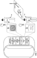
- FIG. 1 is a block diagram illustrating an example wearable computing device that is configured to detect activity transitions, in accordance with one or more techniques of the present disclosure.
- wearable computing device 102 may include sensor control module 104 ("SCM 104"), one or more motion sensors 106, display 108, and one or more application processors 110.
- Wearable computing device 102 may include any number of different portable electronic computing devices, but not limited to, smart watches, smart glasses, headsets, mobile phones (including smartphones), tablet computers, cameras, personal digital assistants (PDAs), etc.
- Wearable computing device 102 may include various input and output components, including, e.g. one or more processors, memory, telemetry modules, cellular network antennas, a display, one or more UI elements, sensors, and a power source like a rechargeable battery. Further details of one example of wearable computing device 102 are described in FIG. 2 .
- Other examples of wearable computing device 102 that implement techniques of this disclosure may include additional components not shown in FIG. 1 .
- wearable computing device 102 may include SCM 104.
- SCM 104 may communicate with one or more of motion sensors 106.
- SCM 104 may be referred to as a "sensor hub" that operates as an input/output controller for one or more of motion sensors 106.
- SCM 104 may exchange data with one or more of motion sensors 106, such as motion data corresponding to wearable computing device 102.
- SCM 104 may also communicate with application processors 110.
- SCM 104 may use less power than application processors 110. As one example, in operation, SCM 104 may use power in a range of 20-200 mW.
- SCM 104 may be referred to as a digital signal processor (DSP) or advanced DSP (ADSP) that operates as an input/output controller for one or more of motion sensors 106.
- wearable computing device 4 may also include a sensor hub (that may be separate from SCM 104) which may operate as an input/output controller for one or more of motion sensors 106.
- the one or more of motion sensors 106 on which the sensor hub operates as the input/output controller may include one or more sensors different than those sensors of motion sensors 106 controlled by SCM 104.
- the sensor hub may operate as an input/output controller for a gyroscope of motion sensors 106 where the gyroscope is not controlled by SCM 104.
- the sensor hub may use more power than SCM 104.
- SCM 104 may analyze motion data received from one or more of motion sensors 106. For instance, SCM 104 may analyze the motion data to determine whether or not a user of wearable computing device 102 has performed a particular gesture of a plurality of gestures. Responsive to determining that the user of wearable computing device 102 has performed a particular gesture of a plurality of gestures, SCM 104 may cause perform an action corresponding to the particular gesture. As one example, responsive to determining that the user of wearable computing device 102 has performed (or is performing) a gesture to view a display of wearable computing device 102, SCM 104 may cause application processors 110 and/or display 108 to transition from a low-power mode to a relatively higher-power mode.
- wearable computing device 102 may include one or more motion sensors 106.
- One or more of motion sensors 106 may measure one more measurands.
- Examples of one or more of motion sensors 106 may include an accelerometer, a gyroscope, or a proximity sensor.
- motion sensors 106 may include accelerometer 131.
- wearable computing device 102 may include display 108.
- Display 108 may output content, such as a graphical user interface (GUI) for display.
- GUI graphical user interface
- display 108 can include a display component and/or a presence-sensitive input component.
- the presence-sensitive input component and the display component may be integrated into a presence-sensitive display, which displays the GUI and receives input from the user using capacitive, inductive, surface acoustic wave, and/or optical detection at or near the presence sensitive display. That is, display 108, in some examples may be a presence-sensitive display.
- the display device can be physically separate from a presence-sensitive device included in wearable computing device 102.
- wearable computing device 102 may include one or more application processors 110.
- One or more application processors 110 may implement functionality and/or execute instructions within wearable computing device 102. These instructions executed by application processors 110 may cause wearable computing device 102 to read/write/etc. information during program execution. Examples of one or more of application processors 110 may include one or more microprocessors, digital signal processors (DSPs), application specific integrated circuits (ASICs), field programmable gate arrays (FPGAs), or any other equivalent integrated or discrete logic circuitry, as well as any combinations of such components.
- DSPs digital signal processors
- ASICs application specific integrated circuits
- FPGAs field programmable gate arrays
- techniques of this disclosure may enable wearable computing device 102 to perform an action corresponding to a particular gesture in response to determining that the user of wearable computing device 102 has performed the particular gesture. For instance, SCM 104 of wearable computing device 102 may determine that the user has performed the particular gesture based on motion data generated by a motion sensor of motion sensors 106.
- SCM 104 may determine whether the user performed a gesture of a plurality of gestures based on one or more motion strokes determined based on motion data that represents movement of wearable computing device 102. In some examples, SCM 104 may determine the one or more motion strokes based on motion data generated by a motion sensor of motion sensors 106. For instance, SCM 104 may segment the motion data into the one or more motion strokes based on features of the motion data such that each of the one or more motion strokes satisfies one or more conditions.
- SCM 104 may generate a respective attribute vector for each respective stroke of the one or more motion strokes.
- Some example attributes which may be included in each respective attribute vector include, but are not limited to, spatial attributes (e.g., coordinates of the endpoints of the stroke, distance traversed by the stroke, directionality of the stroke), temporal attributes (e.g., duration of the stroke, start time of the stroke, end time of the stroke), and relational attributes (e.g., whether other motion strokes with similar attributes are present).
- SCM 104 may classify each respective stroke from the one or more motion strokes into at least one category. For instance, SCM 104 may classify each respective stroke as a "tilt” stroke or a "non-tilt” stroke.
- SCM 104 may determine whether the one or more motion strokes correspond to a known gesture. For instance, SCM 104 may compare the one or more categories of the respective motion strokes to a gesture library to determine whether the one or more motion strokes correspond to a gesture described by the gesture library. Responsive to determining that the one or more motion strokes correspond to a particular gesture described by the gesture library, SCM 104 may perform an action corresponding to the particular gesture. In this way, as opposed to directly analyzing motion data, SCM 104 may determine whether or not a user of wearable computing device 102 performed a particular gesture based on motion strokes.
- the techniques of this disclosure are not limited to such a gesture.
- the techniques of this disclosure may enable a wearable computing device to determine that the user of the wearable computing device has performed a gesture to answer a call (e.g., by lifting the wearable computing device to their ear), a gesture to ignore a call (e.g., by waiting the wearable computing device from side to side), a volume-up gesture (e.g., by pumping their fist in the air), and the like.
- wearable computing device 102 may determine whether a user of wearable computing device 102 performed a gesture to view a display of wearable computing device 102 (e.g., display 108).
- wearable computing device 102 may be in a first orientation.
- wearable computing device 102 may be in first orientation 114 in which wearable computing device 102 may be at the user's side.
- V z and V y may be perpendicular to gravity vector G
- V x may be parallel to gravity vector G such that a plane on display 108 is parallel to the X-Z plane.
- first orientation 114 may be different than as illustrated in FIG.
- wearable computing device 102 may be in a low-power mode in which one or more components of wearable computing device 102 may be off, deactivated, sleeping, have limited functionality, etc.
- display 108 and application processors 110 may operating in a low-power mode.
- display 108 may output GUI 120A which may be dimmed to conserve power. In this way, wearable computing device 102 may consume a reduced amount of power in the low-power mode when compared to a high-powered operating state (e.g., with display 108 and application processors 110 being fully powered).
- SCM 104 may determine receive motion data generated by a motion sensor of motion sensors 106.
- the motion sensor of motion sensors 106 is a three-axis accelerometer 131
- SCM 104 may receive the motion data in the form of a plurality of acceleration vectors each having a respective V x value corresponding to the acceleration in the X axis, a respective V y value corresponding to the acceleration in the Y axis, and a respective V z value corresponding to the acceleration in the Z axis.
- SCM 104 may receive an acceleration vector of approximately (+9.81, 0, 0).
- a user may attempt to use wearable computing device 102 by, for example, moving his/her arm/wrist in an attempt to view display 108 of wearable computing device 102. For instance, the user may move wearable computing device 102 from a first (e.g., orientation 114) to a second orientation (e.g., orientation 116 by moving his/her arm/wrist.
- the motion sensors of motion sensors 106 may detect the user's movement and SCM 104 may determine a plurality of motion vectors based on the motion data generated by the motion sensors in response to detecting the user's movement.
- SCM 104 determines one or more motion strokes based on the received motion data.
- SCM 104 determines the one or more motion strokes by segmenting the received motion data based on features of the motion data. For instance, SCM 104 determines a start point for a particular stroke as a local minimum in the received motion data and an end point for the particular stroke as a point in the received motion data having a high rate of change (e.g., 0.05 units in accelerometer data per 10 sequential samples).
- a high rate of change e.g., 0.05 units in accelerometer data per 10 sequential samples.
- SCM 104 may determine a single stroke that corresponds to the motion data generated by the motion sensor of motion sensors 106 as wearable computing device 102 transition from first orientation 114 to second orientation 116.
- SCM 104 may filter the received motion data prior to determining the one or more motion strokes. For instance, SCM 104 may determine the one or more motion strokes based on lowpass filtered motion data.
- SCM 104 generates a respective attribute vector for each respective stroke of the one or more motion strokes. For instance, in the example of FIG. 1 , SCM 104 may determine, for the single stroke, a respective attribute vector that indicates one or more of: coordinates that correspond to the orientation of wearable computing device at first orientation 114, coordinates that correspond to the orientation of wearable computing device at second orientation 116, directionality of the single stroke, a distance traversed by the single stroke, and a temporal duration of the single stroke.
- SCM 104 classifies each respective stroke from the one or more motion strokes into at least one category. For instance, in the example of FIG. 1 , SCM 104 may classify the single stroke as a "tilt" stroke by comparing the attribute vector corresponding to the single stroke to training data based on attribute vectors that are known to correspond to "tilt" motion strokes.
- SCM 104 determines whether the one or more motion strokes correspond to a gesture by comparing the categories of the one or more motion strokes to a gesture library.
- the gesture library may indicate that a gesture to view a display of a wearable computing device is defined by a single "tilt" stroke.
- SCM 104 classified the single stroke as a "tilt" stroke, SCM 104 determines that the user of wearable computing device 102 has performed a gesture to view a display of wearable computing device 102 and performs a corresponding action.
- FIG. 1 the gesture library may indicate that a gesture to view a display of a wearable computing device is defined by a single "tilt" stroke.
- SCM 104 determines that the user of wearable computing device 102 has performed a gesture to view a display of wearable computing device 102 and performs a corresponding action.
- SCM 104 may output a signal to one or more other components of wearable computing device 102 that causes application processor 110 and/or display 108 to transition from operation in a low-power mode to operation in a higher-power mode.
- display 108 may output GUI 120B at a higher brightness than GUI 120A. In this way, as opposed to requiring that the user of wearable computing device 102 provide additional input, techniques of this display may enable wearable computing device 102 to activate a display in response to determining that the user is attempting to view the display of wearable computing device 102.
- FIG. 2 is a block diagram illustrating an example computing device, in accordance with one or more techniques of the present disclosure.
- FIG. 2 illustrates one particular example of wearable computing device 202, and many other examples of wearable computing device 202 may be used in other instances and may include a subset of the components included in example wearable computing device 202 or may include additional components not shown in FIG. 2 .
- wearable computing device 202 includes one or more application processors 210, one or more output components 250, presence-sensitive display 256, battery 252, sensor control module 204 ("SCM 204"), one or more storage devices 260, and one or more input components 248.
- Storage devices 260 of wearable computing device 202 may also include application modules 242A-242N (collectively, "application modules 242"), user interface module 244 ("UIM 244") and operating system 246.
- Wearable computing device 202 can include additional components that, for clarity, are not shown in FIG. 2 .
- wearable computing device 202 can include a communication unit to enable wearable computing device 202 to communicate with other devices.
- the components of wearable computing device 202 shown in FIG. 2 may not be necessary in every example of wearable computing device 202.
- wearable computing device 202 may not include output components 250.
- Communication channels 254 may interconnect each of the components 204, 210, 248, 250, 252, 546, and 260 for inter-component communications (physically, communicatively, and/or operatively).
- communication channels 254 may include a system bus, a network connection, an inter-process communication data structure, or any other method and/or structure for communicating data.
- One or more application processors 210 may implement functionality and/or execute instructions within wearable computing device 202.
- application processors 210 on wearable computing device 202 may receive and execute instructions stored by storage devices 260 that execute the functionality of modules 242, 244, and 246. These instructions executed by application processors 210 may cause wearable computing device 202 to read/write/etc. information, such as one or more data files stored within storage devices 260 during program execution.
- Application processors 210 may execute instructions of modules 242, 244, and 246 to cause presence-sensitive display 256 to output one or more graphical indications of incoming communications for display at presence-sensitive display 256 as content of a user interface.
- application modules 242, UIM 244, and operating system 246 may be operable by application processors 210 to perform various actions or functions of wearable computing device 202, for instance, causing presence-sensitive display 256 to a present a graphical user interface at display component 208 of presence-sensitive display 256.
- One or more input components 248 of wearable computing device 102 may receive input. Examples of input are tactile, audio, and video input.
- One or more of input devices 44 of wearable computing device 4 may include a presence-sensitive display, touch-sensitive screen, mouse, keyboard, voice responsive system, video camera, microphone, or any other type of device for detecting input from a human or machine.
- input components 248 may include one or more motion sensors 206, which may be configured to perform operations similar to motion sensors 106 of FIG. 1 .
- motion sensors 206 may generate motion data, such as a sequence of motion vectors, that indicates movement (e.g., data representing movement) associated with wearable computing device 202.
- input components 248 may include one or more other sensors, such as one or more location sensors (e.g., a global positioning system (GPS) sensor, an indoor positioning sensor, or the like), one or more light sensors, one or more temperature sensors, one or more pressure (or grip) sensors, one or more physical switches, one or more proximity sensors, and one or more bio-sensors that can measure properties of the skin/blood, such as oxygen saturation, pulse, alcohol, blood sugar etc.
- location sensors e.g., a global positioning system (GPS) sensor, an indoor positioning sensor, or the like
- GPS global positioning system
- one or more of input components 248 may include one or more processors.
- one or more of input components 248, such as one or more of motion sensors 206 may include one or more microprocessors, digital signal processors (DSPs), application specific integrated circuits (ASICs), field programmable gate arrays (FPGAs), or any other equivalent integrated or discrete logic circuitry, as well as any combinations of such components.
- one or more of input components 248 may include one or more storage devices configured to store measurements.
- the one or more storage devices included in one or more of input components 248 may be similar to storage devices 260 as described herein.
- an accelerometer 231 of the one or more motion sensors 206 may include a register, such as a first-in-first-out (FIFO) register, configured to store a quantity of measurements (e.g., 10, 100, 1000, 10000, etc.) of accelerative force over one or more axes (e.g., one-axis, two-axis, or three-axis).
- a register such as a first-in-first-out (FIFO) register, configured to store a quantity of measurements (e.g., 10, 100, 1000, 10000, etc.) of accelerative force over one or more axes (e.g., one-axis, two-axis, or three-axis).
- a register such as a first-in-first-out (FIFO) register
- One or more output components 250 of wearable computing device 202 may generate output. Examples of output are tactile, audio, and video output.
- Output components 250 includes a presence-sensitive display, sound card, video graphics adapter card, speaker, electronic display, or any other type of device for generating output to a human or machine.
- the electronic display may be an LCD or OLED part of a touch screen, may be a non-touchscreen direct view display component such as a CRT, LED, LCD, or OLED.
- the display component may also be a projector instead of a direct view display.
- Presence-sensitive display 256 of wearable computing device 202 includes display component 208 and presence-sensitive input component 258.
- Display component 208 may be a screen at which information is displayed by presence-sensitive display 256 and presence-sensitive input component 258 may detect an object at and/or near display component 208.
- a presence-sensitive input component 258 may detect an object, such as a finger or stylus that is within 2 inches (-5.08 centimeters) or less from display component 208.
- Presence-sensitive input component 258 may determine a location (e.g., an (x,y) coordinate) of display component 208 at which the object was detected.
- presence-sensitive input component 258 may detect an object 6 inches (-15.24 centimeters) or less from display component 208 and other exemplary ranges are also possible. Presence-sensitive input component 258 may determine the location of display component 208 selected by a user's finger using capacitive, inductive, and/or optical recognition techniques. In some examples, presence sensitive input component 258 also provides output to a user using tactile, audio, or video stimuli as described with respect to display component 208. In the example of FIG. 2 , presence-sensitive display 256 presents a user interface (such as user interface 120A or user interface 120B of FIG. 1 ).
- presence-sensitive display 256 may also represent and external component that shares a data path with wearable computing device 202 for transmitting and/or receiving input and output.
- presence-sensitive display 256 represents a built-in component of wearable computing device 202 located within and physically connected to the external packaging of wearable computing device 202 (e.g., a screen on a mobile phone).
- presence-sensitive display 256 represents an external component of wearable computing device 202 located outside and physically separated from the packaging of wearable computing device 202 (e.g., a monitor, a projector, etc. that shares a wired and/or wireless data path with a tablet computer).
- SCM 204 may collect and analyze sensor data. For instance, SCM 204 may collect any analyze sensor data from one or more of motion sensors 206 (e.g., accelerometer 231). As illustrated in FIG. 2 , SCM 204 may include one or more processors 222, filtering module 226, stroke module 228, transform module 230, attribute module 232, classification module 234, gesture module 236, and gesture library 238. In some examples, SCM 204 may be a discrete component within wearable computing device 202. In some examples, SCM 204 may be integrated into one or more other components of wearable computing device 202, such as one or more of application processors 210. In some examples, SCM 204 may include additional components that, for simplicity, are not shown in FIG 2 .
- SCM 204 may include one or more analog-to-digital converters which may facilitate communication between one or more of input components 248 and one or more of processors 222. Additionally, SCM 204 may include one or more storage devices which may store filtering module 226, stroke module 228, transform module 230, attribute module 232, classification module 234, gesture module 236, and gesture library 238. In some examples, the one or more storage devices included in SCM 204 may be similar to storage devices 260 as described below.
- Processors 222 may implement functionality and/or execute instructions within SCM 204.
- processors 222 may receive and execute instructions stored by a storage device that execute the functionality of filtering module 226, stroke module 228, transform module 230, attribute module 232, classification module 234, and/or gesture module 236. These instructions executed by one or more of processors 222 may cause SCM 204 to read/write/etc. information, such as one or more data files stored within a storage device during program execution.
- Filtering module 226 may be executable by one or more of processors 222 to filter sensor data measured by one or more of motion sensors 206. For instance, filtering module 226 may filter a sequence of motion vectors received from an accelerometer 231 of one or more motion sensors 206. In some examples, the motion vectors may represent a combination of different forces. For instance, the motion vectors may represent both the (a) gravity force that may register as low-frequency components, which varies with the 3D orientation of wearable computing device 202, and (b) impulses applied to wearable computing device 202 that may register as high-frequency components (i.e., as the user moves his or her arm).
- filtering module 226 may filter the sequence of motion vectors by separating the low frequency components from the high frequency components (e.g., using symmetric kernels). Filtering module 226 may output the low frequency components to one or more components of wearable computing device 202, such as stroke module 228 and/or transform module 230, as filtered motion vectors.
- Stroke module 228 may be executable by one or more of processors 222 to determine one or more motion strokes based on motion data. For instance, stroke module 228 may determine the one or more motion strokes based on a sequence of filtered motion vectors received from filtering module 226. In some examples, stroke module 228 may determine the one or more motion strokes using the filtered motion vectors in the original coordinate system. In some examples, stroke module 228 may determine the one or more motion strokes using filtered motion vectors converted into a task-specific coordinate system as described below. In any case, stroke module 228 may output an indication of the determined motion strokes to one or more components of wearable computing device 202, such as attribute module 232.
- stroke module 228 may determine motion strokes as movements of wearable computing device 202 that satisfy one or more conditions.
- a stroke may be temporally compact such that the duration of the stroke is less than a pre-defined maximum stroke duration (e.g., 1 second, 2, seconds, 5 seconds, 10 seconds).
- a stroke may have a non-trivial orientation change such that the distance, such as the geodesic distance, between the first orientation of the stroke and the last orientation of the stroke is greater than a pre-defined minimum change in orientation (e.g., 0.001 on a scale of 0 to 2, 0.1, etc.).
- a stroke may be monotonic such that the distance from the first orientation of the stroke and the last orientation of the stroke increases monotonically along the entire stroke. For instance, for every pair of motion vectors in a stroke (i.e., (m_i, m_j)) such that j > i, the following may be true: d(m_j, m_0) > d(m_i, m_0), where m_0 is the motion vector corresponding to the starting boundary of the stroke, and d(m_i, m_0) is the distance between motion vector i and motion vector 0.
- the norm of (u,v) may vary monotonically along the duration of the stroke.
- a stroke may be approximately geodesic such that the stroke happens along a geodesic of the orientation space. For instance, a meaningful stroke may happen along a Meridian defined by the task-specific coordinate system.
- Transform module 230 may be executable by one or more of processors 222 to transform motion data between different coordinate systems. For instance, transform module 230 may convert filtered motion vectors received from filtering module 226 from a first coordinate system to a second coordinate system.
- the first coordinate system may define the orientation of wearable computing device 202 relative to the gravity vector and the second coordinate system may define the orientation of wearable computing device 202 relative to a task-specific orientation.
- the second coordinate system may utilize the orientation of wearable computing device 202 at the end of a look-and-lift gesture (i.e., the orientation of wearable computing device 202 during user interactions) as the task-specific orientation.
- transform module 230 may output the converted motion vectors to one or more other components of wearable computing device 202, such as attribute module 232.
- Attribute module 232 may be executable by one or more of processors 222 to generate an attribute vector for a stroke. For instance, attribute module 232 may generate a respective attribute vector for each respective stroke from the one or more motion strokes received from stroke module 228. Some example attributes which may be included in each respective attribute vector include, but are not limited to, spatial attributes, temporal attributes, and relational attributes. Attribute module 232 may output the attribute vectors to one or more other components of wearable computing device 202, such as classification module 234.
- attribute module 232 may generate the attribute vectors based on a history of measurements collected from the current user of wearable computing device 202, a history of measurements collected from other users of wearable computing device 202, a history of measurements collected from users of other wearable computing devices, or any combination of the same.
- wearable computing device 202 discussed herein may collect personal information about users, or may make use of personal information, the users may be provided with an opportunity to control whether programs or features collect user information (e.g.
- certain data may be treated in one or more ways before it is stored or used, so that personally identifiable information is removed.
- a user's identity may be treated so that no personally identifiable information can be determined for the user, or a user's geographic location may be generalized where location information is obtained (such as to a city, ZIP code, or state level), so that a particular location of a user cannot be determined.
- the user may have control over how information is collected about the user and used by a content server.
- Classification module 234 may be executable by one or more of processors 222 to classify motion strokes into at least one category. For instance, classification module 234 may classify each respective stroke from the one or more motion strokes received from stroke module 228 into at least one category based on respective corresponding attribute vectors received from attribute module 232. Classification module 234 may output the respective categories for the respective motion strokes to one or more other components of wearable computing device 202, such as gesture module 236. In this way, classification module 234 may use the strokes as lexical units for gesture recognition.
- Gesture module 236 may be executable by one or more of processors 222 to determine whether or not a user associated with wearable computing device 202 has performed (or is performing) a gesture. In some examples, gesture module 236 may determine whether the user has performed a gesture based on the respective categories for the respective one or more motion strokes and a gesture library, such as gesture library 238. In some examples, some entries in gesture library 238 may correspond to a single stroke. In some examples, gesture module 236 may accommodate uncertainty in the recognition of individual motion strokes. For instance, gesture module 236 may implement one or more of Hidden Markov Models (HMMs), particle filters, and/or similar multimodal temporal estimation techniques when determining whether or not the user has performed a gesture.
- HMMs Hidden Markov Models
- Gesture library 238 may include one or more entries that may each correspond to a particular gesture.
- a first entry in gesture library 238 may indicate that a single stroke in a first category corresponds to a first gesture.
- an entry in gesture library 238 may indicate that a single stroke classified as tilt may correspond to a lift-and-look gesture.
- a second entry in gesture library 238 may indicate that a particular sequence of motion strokes in a respective sequence of categories corresponds to a second gesture.
- an entry in gesture library 238 may indicate that a first stroke classified as twist-away (e.g., the user supinates their hand) followed by a second stroke classified as twist-toward (e.g., the user pronates their hand) may correspond to a wrist flick gesture
- each respective entry in gesture library 238 may indicate one or more actions associated with the respective gesture.
- an entry for the look-and-lift gesture may indicate actions of transitioning one or more components of wearable computing device 202 from a low power mode to a higher power mode.
- One or more storage devices 260 within wearable computing device 202 may store information for processing during operation of wearable computing device 202 (e.g., wearable computing device 202 may store data that modules 242 and 244 and operating system 246 may access during execution at wearable computing device 202).
- storage device 260 is a temporary memory, meaning that a primary purpose of storage device 260 is not long-term storage.
- Storage devices 260 on wearable computing device 202 may configured for short-term storage of information as volatile memory and therefore not retain stored contents if powered off. Examples of volatile memories include random access memories (RAM), dynamic random access memories (DRAM), static random access memories (SRAM), and other forms of volatile memories known in the art.
- Storage devices 260 also include one or more computer-readable storage media. Storage devices 260 may store larger amounts of information than volatile memory. Storage devices 260 may further be configured for long-term storage of information as non-volatile memory space and retain information after power on/off cycles. Examples of non-volatile memories include magnetic hard discs, optical discs, floppy discs, flash memories, or forms of electrically programmable memories (EPROM) or electrically erasable and programmable (EEPROM) memories. Storage devices 260 may store program instructions and/or information (e.g., data) associated with application modules 242, UIM 244, and operating system 246.
- program instructions and/or information e.g., data
- Operating system 246, controls the operation of components of wearable computing device 202.
- operating system 246, in one example, facilitates the communication of application modules 242 with application processors 210, one or more input components 248, one or more output components 250, presence-sensitive display 256, and SCM 204.
- Each of application modules 242 may include program instructions and/or data that are executable by wearable computing device 202 (e.g., by one or more application processors 210).
- UIM 244 may cause presence-sensitive display 256 to output a graphical user interface (e.g., graphical user interfaces 120A, 120B of FIG. 1 ) for display, which may enable a user of wearable computing device 202 to view output and/or provide input at presence-sensitive input component 258.
- UIM 244 and presence-sensitive display 256 may receive one or more indications of input from a user as the user interacts with the graphical user interface, at different times and when the user and wearable computing device 202 are at different locations.
- UIM 244 and presence-sensitive input component 258 may interpret inputs detected at presence-sensitive input component 258 (e.g., as a user provides one or more gestures at one or more locations of presence-sensitive display 256 at which the graphical user interface is displayed) and may relay information about the inputs detected at presence-sensitive input component 258 to one or more associated platforms, operating systems, applications, and/or services executing at wearable computing device 202, to cause wearable computing device 202 to perform functions.
- UIM 244 may receive information and instructions from one or more associated platforms, operating systems, applications, and/or services executing at wearable computing device 202 (e.g., application modules 242) for generating a graphical user interface.
- UIM 244 may act as an intermediary between the one or more associated platforms, operating systems, applications, and/or services executing at wearable computing device 202 and various output devices of wearable computing device 202 (e.g., speakers, LED indicators, audio or electrostatic haptic output device, etc.) to produce output (e.g., a graphic, a flash of light, a sound, a haptic response, etc.) with wearable computing device 202.
- output devices e.g., speakers, LED indicators, audio or electrostatic haptic output device, etc.
- Battery 252 may provide power to one or more components of wearable computing device 202.
- Examples of battery 252 may include, but are not necessarily limited to, batteries having zinc-carbon, lead-acid, nickel cadmium (NiCd), nickel metal hydride (NiMH), lithium ion (Li-ion), and/or lithium ion polymer (Li-ion polymer) chemistries.
- Battery 252 may have a limited capacity (e.g., 1000-3000 mAh).
- Modules 226, 228, 230, 232, 234, 236, 242, and 244 may perform operations described herein using software, hardware, firmware, or any combination of hardware, software, and firmware residing in and executing on wearable computing device 202.
- Wearable computing device 202 may execute modules 226, 228, 230, 232, 234, 236, 242, and 244 with multiple processors.
- Wearable computing device 202 may execute any of modules 226, 228, 230, 232, 234, 236, 242, and 244 as or within a virtual machine executing on underlying hardware.
- Modules 226, 228, 230, 232, 234, 236, 242, and 244 may be implemented in various ways.
- any of modules 226, 228, 230, 232, 234, 236, 242, and 244 may be implemented as a downloadable or pre-installed application or "app.”
- any of modules 226, 228, 230, 232, 234, 236, 242, and 244 may be implemented as part of an operating system of wearable computing device 202.
- the period of time for which wearable computing device 202 may operate with power provided by battery 252 may be based on the amount of power consumed by wearable computing device 202. As such, in order to increase the period of time for which wearable computing device 202 may operate with power provided by battery 252, it may be desirable to reduce the amount of power consumed by wearable computing device 202. As it may be undesirable to reduce performance while a user is interacting with (i.e., using) wearable computing device 202, it may be desirable to reduce the amount of power consumed by wearable computing device 202 while not in use by the user.
- wearable computing device 202 may determine whether a user of wearable computing device 202 performed a gesture of a plurality of gestures based on motion data that represents movement of wearable computing device 202.
- a motion sensor of motion sensors 206 e.g., an accelerometer
- the motion sensor of motion sensors 206 may perform analysis on the plurality of motion vectors.
- a processor of accelerometer 231 may determine whether or not a value based on the plurality of motion vectors satisfies a threshold. Responsive to determining that the value satisfies the threshold, the motion sensor of motion sensors 206 may output a signal that causes SCM 204 to transition from operating in the low-power mode into a higher-power mode. In this way, the motion sensor of motion sensors 206 may reduce the amount of power consumed by SCM 204. For instance, by performing a preliminary analysis of the motion data, the processor of accelerometer 231 may allow SCM 204 to avoid continually analyzing the raw motion data. In any case, the motion sensor of motion sensors 206 may output the plurality of motion vectors to SCM 204.
- Filtering module 226 of SCM 204 may filter the plurality of motion vectors to determine a plurality of filtered motion vectors. For instance, filtering module 226 may remove higher-frequency components from the plurality of motion vectors.
- Stroke module 228 may determine one or more motion strokes based on the filtered motion vectors. For instance, stroke module 228 may determine one or more local minima from the filtered motion vectors. The determined one or more local minima may represent either a starting boundary of a stroke or an ending boundary of a stroke. Stroke module 228 may process each of the one or more local minima to determine a corresponding stroke starting boundary, ending boundary, or both. In some examples, stroke module 228 may determine the one or more motion strokes based on motion data corresponding to each of a plurality of axes represented by the motion vectors (i.e., X, Y, and Z axes).
- stroke module 228 may determine the one or more motion strokes based on motion data corresponding to a particular axis of the plurality of axes. For example, stroke module 228 may determine the one or more motion strokes based on motion data corresponding to the Y axis (e.g., V y values as illustrated in FIG. 1 ).
- Stroke module 228 may determine whether the determined local minima correspond to a curvature or a plateau. For instance, to determine whether a particular local minima corresponds a curvature or plateau, stroke module 228 may determine a standard deviation for the particular local minima (e.g., based on surrounding motion vectors). If the standard deviation is greater than a threshold (e.g., 0.1 in accelerometer data per 40 sequential values, standard deviation of 2.5 in gravity per second, etc.), stroke module 228 may determine that the particular local minima corresponds to a curvature. If the standard deviation is less than the threshold (e.g., 0.1 in accelerometer data per 40 sequential values, standard deviation of 2.5 in gravity per second, etc.), stroke module 228 may determine that the particular local minima corresponds to a plateau.
- a threshold e.g., 0.1 in accelerometer data per 40 sequential values, standard deviation of 2.5 in gravity per second, etc.
- stroke module 228 may determine that the particular local minima is a starting boundary of a stroke (i.e., an upward stroke). Stroke module 228 may determine a corresponding ending boundary of the stroke. For instance, stroke module 228 may evaluate subsequent motion vectors to determine a motion vector corresponding to an edge with a low rate of change which may be used as the ending boundary for the stroke. In some examples, stroke module 228 may continue to evaluate subsequent motion vectors (i.e., motion vectors temporally after the motion vector used as the end boundary) to determine a motion vector corresponding to an edge with a high rate of change. Stroke module 228 may determine that the motion vector corresponding to the edge with a high rate of change is a starting boundary for another stroke (i.e., a downward stroke).
- stroke module 228 may evaluate subsequent motion vectors to determine a motion vector corresponding to an edge with a high rate of change. Stroke module 228 may determine that the motion vector corresponding to the edge with a high rate of change is a starting boundary for a stroke (i.e., a downward stroke). In some examples, stroke module 228 may discard stroke that do not satisfy one or more criteria (such as motion strokes with a change in magnitude less than a threshold change in magnitude).
- Transform module 230 may generate task-specific motion data by converting the motion vectors corresponding to the one or more motion strokes into a task-specific coordinate system.
- transform module 230 may convert the motion vectors into the task-specific coordinate system as follows, where z_t is a typical orientation of the gravity vector during user interactions with wearable computing device 202 (e.g., the orientation of the gravity vector while wearable computing device 202 is in orientation 116 as illustrated in FIG.1 , as one example z_t , in the x,y,z coordinate system, may be [0.0, 0.66, 0.75]):
- the coordinates (u, v) as specified above cover the entire hemisphere around z_t (or alternatively the opposite hemisphere) without ambiguities or singularities. In some examples, "a” may be included for complete generality.
- the task-centric coordinates (a, u, v) may be such that:
- Attribute module 232 may generate a respective attribute vector for each respective stroke of the one or more motion strokes. For instance, attribute module 232 may generate an attribute vector for a particular stroke of the one or more motion strokes that includes one or more of: spatial attributes, temporal attributes, and relational attributes.
- Some example spatial attributes which may be included in each respective attribute vector include, but are not limited to, a near orientation attribute may indicate an endpoint of the respective stroke closest to a particular orientation, such as the task-specific orientation; a far orientation attribute that may indicate an endpoint of the respective stroke furthest from the particular orientation, such as the task-specific orientation; a polarity attribute that may indicate whether the respective stroke was from the far orientation to the near orientation or vice versa; an azimuth attribute that may indicate directionality of the respective stroke, such as the direction of the respective stroke's temporal derivative at the endpoint of the respective stroke closest to the particular orientation, or a pre-defined linear combination of the temporal derivative directions along the entire stroke, which, in some examples, may be biased toward the endpoint of the respective stroke closest to a particular orientation; and an amplitude attribute which may indicate a distance, such as a geodesic distance, between the endpoints of the respective stroke (i.e., a distance between the endpoint of the respective stroke furthest from the particular orientation and the endpoint of the
- temporal attributes which may be included in each respective attribute vector include, but are not limited to, a duration attribute which may indicate a duration of the stroke, a start time attribute which may indicate a start time of the stroke, and an end time attribute which may indicate an end time of the stroke.
- each respective attribute vector includes, but are not limited to, a periodicity attribute which may indicate the presence or absence of other motion strokes with similar properties at regular intervals (e.g., within a relatively small temporal neighborhood, such as the previous 5, 10, 20 motion strokes, of the respective stroke), and an anomaly attribute which may indicate the presence or absence of other motion strokes with similar properties within a history of measurements (e.g., a history of measurements collected from the current user of wearable computing device 202, a history of measurements collected from other users of wearable computing device 202, a history of measurements collected from users of other wearable computing devices, or any combination of the same).
- a periodicity attribute which may indicate the presence or absence of other motion strokes with similar properties at regular intervals (e.g., within a relatively small temporal neighborhood, such as the previous 5, 10, 20 motion strokes, of the respective stroke)
- an anomaly attribute which may indicate the presence or absence of other motion strokes with similar properties within a history of measurements (e.g., a history of measurements collected from the
- classification module 234 may classify each respective stroke of the one or more motion strokes into at least one category based on respective corresponding attribute vectors received from attribute module 232.
- classification module 234 may classify each respective stroke using a binary classifier, such as standard Support Vector Machines (SVMs). For instance, when classifying a stroke as tilt or non-tilt, classification module 234 may use a binary classifier to classify each respective stroke as either tilt or non-tilt.
- SVMs Support Vector Machines
- classification module 234 may classify each respective stroke based on a distance function between respective attribute vectors of the motion strokes. For instance, classification module 234 may train a distance function between stroke attribute vectors and cluster the motion strokes according to the distance function. Classifying motion strokes based on the distance function may have the advantage of picking up "natural" stroke classes that users perform when they are wearing wearable computing devices. For instance, gestures may be designed to match the natural classes.
- classification may initially be performed with a basic attribute space and used to bootstrap a richer attribute space. For instance, classification may be initially performed without one or more attributes (e.g., the periodicity attribute and/or the anomaly attribute). In this way, classification module 234 may be trained over time to classify motion strokes into new categories.
- classification module 234 may classify each respective stroke using deep belief networks (DBNs). For instance, classification module 234 may use training data that includes data triplets of motion strokes ⁇ A, B, C ⁇ such that the A and B are semantically much closer than either one of them and C. Classification module 234 may use the raw signals (e.g., motion data unfiltered by filtering module 226) as input to the DBNs (e.g., in a fixed temporal window). However, in some examples, using raw signals may use a large amount of data. In some examples, the input to the DBNs may include positive samples and/or negative samples.
- DBNs deep belief networks
- a positive sample may be a sample where the signals belong to a "desired” category (e.g., if we are classifying "tilt” vs "non-tilt” gestures the positive samples are the collected signals for an actual tilt). Conversely, negative samples may be samples that are not in the "desired” category (in the example below, those would be the non-tilt gestures).
- classification module 234 may use random windows of the negative samples.
- classification module 234 may apply various transformations to the positive samples (where the positive samples may be invariant to the transformations).
- gesture module 236 may determine whether or not the user has performed (or is performing) a gesture based on the respective categories for the one or more motion strokes. For instance, gesture module 236 may search gesture library 238 to determine whether or not the respective categories for the respective one or more motion strokes correspond to one or more entries in gesture library 238. Responsive to determining that the respective categories for the respective one or more motion strokes correspond to a particular entry in gesture library 238, gesture module 236 may determine that the user has performed a gesture corresponding to the particular entry and cause wearable computing device 202 to perform an action indicated by the particular entry.
- gesture module 236 may send an interrupt signal to application processor 210 that causes application processor 210 to transition from operating in a low-power mode to operating in a higher-power mode.
- application processor 210 may send a signal to display component 208 that causes display component 208 to output a GUI, such as GUI 120B of FIG. 1 .
- gesture module 236 may send a signal to display component 208 that causes display component 208 to activate (e.g., turn on).
- FIGS. 3A and 3B are conceptual diagrams illustrating conversion of motion data from a first coordinate system into a second, task-specific, coordinate system.
- X, Y, and Z may represent the X, Y, and Z axes of a motion sensor included in a wearable device, such as an accelerometer 231 of motion sensors 206 of wearable computing device 202 of FIG. 2 .
- the Z axis may be normal to the surface of a display of wearable computing device 202 (e.g., display component 208), the Y axis may be parallel to the vertical dimension of the display, and the X axis may be parallel to the horizontal dimension of the display.
- a wearable computing device such as wearable computing device 202, may convert motion data from a first coordinate system into a second, task-specific, coordinate system.
- transform module 230 may convert motion data generated by a motion sensor of motion sensors 206 (e.g., an accelerometer 231) into a gaze-centric coordinate system.
- the vector z_t may be defined as the typical orientation of gravity vector G while a user is expected to be interacting with wearable computing device 202 (i.e., while the user is "gazing" at a display of wearable computing device 202). Based on z_t , the vectors x_t and y_t may be defined.
- transform module 230 may convert motion vectors including x,y,z values (corresponding to the X, Y, and Z axes) into u,v coordinates. Transform module 230 may normalize the x,y,z values of a motion vector into unit length to determine motion vector m . Transform module 230 may determine vector motion vector m_p by projecting motion vector m on to a plane of display component 208 and extending the result to unit length (i.e., to intersect with circle 362).
- a task-specific e.g., a gaze-centric
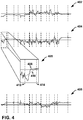
- FIG. 4 is a graph illustrating example motion data generated by a motion sensor of a wearable computing device as a function of time, in accordance with one or more techniques of the present disclosure.
- the motion data illustrated by graph 402 of FIG. 4 may correspond to X-axis motion data
- the motion data illustrated by graph 404 of FIG. 4 may correspond to Y-axis motion data
- the motion data illustrated by graph 406 of FIG. 4 may correspond to Z-axis motion data generated by an accelerometer 131 of the one or more motion sensors 106 of wearable computing device 102 of FIG. 1 or an accelerometer 231 of the one or more motion sensors 206 of wearable computing device 202 of FIG. 2 .
- wearable computing device 202 may determine one or more motion strokes based on motion data generated by a an accelerometer of wearable computing device 202. For instance, as illustrated in expanded view 405 of graph 404, an accelerometer 231 of the one or more motion sensors 206 may generate Y-axis motion data 408, which may include a sequence of values. Filtering module 226 may filter Y-axis motion data 408 to generate filtered Y-axis motion data 410. Stroke module 228 of SCM 204 may determine the one or more motion strokes based on filtered Y-axis motion data 410.
- stroke module 228 may determine that the value of filtered Y-axis motion data 410 corresponding to time 412 is a local minima. Stroke module 228 may determine whether the local minima corresponds to a curvature or a plateau of filtered Y-axis motion data 410. For instance, stroke module 228 may determine that the local minima corresponds to a curvature where a standard deviation of values of filtered Y-axis motion data 410 temporally surrounding the local minima is greater than a threshold.
- stroke module 228 may determine that the local minima is a starting boundary of a stroke, such as an upward stroke. Stroke module 228 may evaluate values of filtered Y-axis motion data 410 subsequent to time 412 to determine a value corresponding to an edge of filtered Y-axis motion data 410, such as an edge with a low rate of change. For instance, stroke module 228 may determine that the value of filtered Y-axis motion data 410 corresponding to time 414 is an edge. Stroke module 228 may determine that the value of filtered Y-axis motion data 410 corresponding to time 414 is an ending boundary of the stroke. In this way, stroke module 228 may determine one or more motion strokes based on motion data generated by a motion sensor of wearable computing device 202 based on features of the filtered motion data.
- stroke module 228 may output an indication of the determined one or more motion strokes to attribute module 232, which may generate a respective attribute vector for each stroke of the one or more stokes.
- FIG. 5 is a block diagram illustrating an example computing device that outputs graphical content for display at a remote device, in accordance with one or more techniques of the present disclosure.
- Graphical content generally, may include any visual information that may be output for display, such as text, images, a group of moving images, etc.
- the example shown in FIG. 5 includes a computing device 502, presence-sensitive display 556, communication unit 568, projector 578, projector screen 580, mobile device 584, and visual display device 588. Although shown for purposes of example in FIGS.
- a computing device such as computing device 502 may, generally, be any component or system that includes a processor or other suitable computing environment for executing software instructions and, for example, need not include a presence-sensitive display.
- computing device 502 may be a processor that includes functionality as described with respect to application processor 210 or SCM 204 in FIG. 2 .
- computing device 502 may be operatively coupled to presence-sensitive display 556 by a communication channel 566A, which may be a system bus or other suitable connection.
- Computing device 502 may also be operatively coupled to communication unit 568, further described below, by a communication channel 566B, which may also be a system bus or other suitable connection.
- computing device 502 may be operatively coupled to presence-sensitive display 556 and communication unit 568 by any number of one or more communication channels.
- a computing device may refer to a portable or mobile device such as mobile phones (including smart phones), wearable computing devices (including smart watches and headsets) laptop computers, etc.
- Presence-sensitive display 556 may include display component 508 and presence-sensitive input component 558.
- Display component 508 may, for example, receive data from computing device 502 and display the graphical content.
- presence-sensitive input component 558 may determine one or more user inputs (e.g., continuous gestures, multi-touch gestures, single-touch gestures, etc.) at presence-sensitive display 556 using capacitive, inductive, and/or optical recognition techniques and send indications of such user input to computing device 502 using communication channel 566A.
- user inputs e.g., continuous gestures, multi-touch gestures, single-touch gestures, etc.
- presence-sensitive input component 558 may be physically positioned on top of display component 508 such that, when a user positions an input unit over a graphical element displayed by display component 508, the location at which presence-sensitive input component 558 corresponds to the location of display component 508 at which the graphical element is displayed.
- presence-sensitive input component 558 may be positioned physically apart from display component 508, and locations of presence-sensitive input component 558 may correspond to locations of display component 508, such that input can be made at presence-sensitive input component 558 for interacting with graphical elements displayed at corresponding locations of display component 508.
- computing device 502 may also include and/or be operatively coupled with communication unit 568.
- Examples of communication unit 568 may include a network interface card, an Ethernet card, an optical transceiver, a radio frequency transceiver, or any other type of device that can send and receive information.
- Other examples of such communication units may include Bluetooth, 3G, and Wi-Fi radios, Universal Serial Bus (USB) interfaces, etc.
- Computing device 502 may also include and/or be operatively coupled with one or more other devices, e.g., input devices, output devices, memory, storage devices, etc. that are not shown in FIG. 5 for purposes of brevity and illustration.
- FIG. 5 also illustrates a projector 578 and projector screen 580.
- projection devices may include electronic whiteboards, holographic display devices, and any other suitable devices for displaying graphical content.
- Projector 578 and projector screen 580 may include one or more communication units that enable the respective devices to communicate with computing device 502. In some examples, the one or more communication units may enable communication between projector 578 and projector screen 580.
- Projector 578 may receive data from computing device 502 that includes graphical content. Projector 578, in response to receiving the data, may project the graphical content onto projector screen 580.
- projector 578 may determine one or more user inputs (e.g., continuous gestures, multi-touch gestures, single-touch gestures, etc.) at projector screen using optical recognition or other suitable techniques and send indications of such user input using one or more communication units to computing device 502.
- projector screen 580 may be unnecessary, and projector 578 may project graphical content on any suitable medium and detect one or more user inputs using optical recognition or other such suitable techniques.
- Projector screen 580 may include a presence-sensitive display 582.
- Presence-sensitive display 582 may include a subset of functionality or all of the functionality of display 108 as described in this disclosure.
- presence-sensitive display 556 may include additional functionality.
- Projector screen 580 e.g., an electronic whiteboard
- Projector screen 580 may receive data from computing device 502 and display the graphical content.
- presence-sensitive display 582 may determine one or more user inputs (e.g., continuous gestures, multi-touch gestures, single-touch gestures, etc.) at projector screen 580 using capacitive, inductive, and/or optical recognition techniques and send indications of such user input using one or more communication units to computing device 502.
- FIG. 5 also illustrates mobile device 584 and visual display device 588.
- Mobile device 584 and visual display device 588 may each include computing and connectivity capabilities. Examples of mobile device 584 may include e-reader devices, convertible notebook devices, hybrid slate devices, wearable computing devices, etc. Examples of visual display device 588 may include other semi-stationary devices such as televisions, computer monitors, etc.
- mobile device 584 may include a presence-sensitive display 586.
- Visual display device 588 may include a presence-sensitive display 590. Presence-sensitive displays 586, 590 may include a subset of functionality or all of the functionality of display 108 as described in this disclosure. In some examples, presence-sensitive displays 586, 590 may include additional functionality.
- presence-sensitive display 590 may receive data from computing device 502 and display the graphical content.
- presence-sensitive display 590 may determine one or more user inputs (e.g., continuous gestures, multi-touch gestures, single-touch gestures, etc.) at projector screen using capacitive, inductive, and/or optical recognition techniques and send indications of such user input using one or more communication units to computing device 502.
- user inputs e.g., continuous gestures, multi-touch gestures, single-touch gestures, etc.
- computing device 502 may output graphical content for display at presence-sensitive display 556 that is coupled to computing device 502 by a system bus or other suitable communication channel.
- Computing device 502 may also output graphical content for display at one or more remote devices, such as projector 578, projector screen 580, mobile device 584, and visual display device 588.
- computing device 502 may execute one or more instructions to generate and/or modify graphical content in accordance with techniques of the present disclosure.
- Computing device 502 may output the data that includes the graphical content to a communication unit of computing device 502, such as communication unit 568.
- Communication unit 568 may send the data to one or more of the remote devices, such as projector 578, projector screen 580, mobile device 584, and/or visual display device 588.
- computing device 502 may output the graphical content for display at one or more of the remote devices.
- one or more of the remote devices may output the graphical content at a presence-sensitive display that is included in and/or operatively coupled to the respective remote devices.
- computing device 502 may not output graphical content at presence-sensitive display 556 that is operatively coupled to computing device 502.
- computing device 502 may output graphical content for display at both a presence-sensitive display 556 that is coupled to computing device 502 by communication channel 566A, and at one or more remote devices.
- the graphical content may be displayed substantially contemporaneously at each respective device. For instance, some delay may be introduced by the communication latency to send the data that includes the graphical content to the remote device.
- graphical content generated by computing device 502 and output for display at presence-sensitive display 556 may be different than graphical content display output for display at one or more remote devices.
- Computing device 502 may send and receive data using any suitable communication techniques.
- computing device 502 may be operatively coupled to external network 572 using network link 570A.
- Each of the remote devices illustrated in FIG. 4 may be operatively coupled to network external network 572 by one of respective network links 570B, 570C, and 570D.
- External network 572 may include network hubs, network switches, network routers, etc., that are operatively inter-coupled thereby providing for the exchange of information between computing device 502 and the remote devices illustrated in FIG. 5 .
- network links 570A-570D may be Ethernet, ATM or other network connections. Such connections may be wireless and/or wired connections.
- computing device 502 may be operatively coupled to one or more of the remote devices included in FIG. 5 using direct device communication 576.
- Direct device communication 576 may include communications through which computing device 502 sends and receives data directly with a remote device, using wired or wireless communication. That is, in some examples of direct device communication 576, data sent by computing device 502 may not be forwarded by one or more additional devices before being received at the remote device, and vice-versa. Examples of direct device communication 576 may include Bluetooth, Near-Field Communication, Universal Serial Bus, Wi-Fi, infrared, etc.
- One or more of the remote devices illustrated in FIG. 5 may be operatively coupled with computing device 502 by communication links 574A-574D.
- communication links 574A-574D may be connections using Bluetooth, Near-Field Communication, Universal Serial Bus, infrared, etc. Such connections may be wireless and/or wired connections.
- computing device 502 may be operatively coupled to visual display device 588 using external network 572.
- a sensor control module of computing device 502 may determine, based on motion data generated by a motion sensor, a plurality of values. Responsive to determining that each the plurality of values satisfies a corresponding threshold, computing device 502 may send a signal to a display that causes the display to transition from operating in a low-power mode to operating in a higher-power mode.
- computing device 502 may a signal to display component 508 of presence-sensitive display 556, projector 578, presence-sensitive display 586 of mobile device 584, and/or presence-sensitive display 590 of visual display device 588 that causes display component 508 of presence-sensitive display 556, projector 578, presence-sensitive display 586 of mobile device 584, and/or presence-sensitive display 590 of visual display device 588 to transition from operating in a low-power mode to operating in a higher-power mode.
- FIG. 6 is a flow diagram illustrating example operations of a wearable computing device that performs actions based on motion data, in accordance with one or more techniques of the present disclosure.
- the techniques of FIG. 6 may be performed by one or more processors of a computing device, such as wearable computing device 102 or 202 illustrated in FIG. 1 and FIG. 2 .
- the techniques of FIG. 6 are described within the context of wearable computing device 202 of FIG. 2 , although computing devices having configurations different than that of wearable computing device 202 may perform the techniques of FIG. 6 , such as wearable computing device 102 of FIG. 1 .
- one or more of motion sensor of sensors 206 may generate motion data (602). For instance, an accelerometer 231 of motion sensors 206 may generate a plurality of motion vectors that each indicate a respective acceleration value for an X-axis, a Y-axis, and a Z-axis.
- the motion data generated by the motion sensor of motion sensors 206 indicates movement of wearable computing device 202, such as movement of wearable computing device 202 during a first time period.
- one or more components of wearable computing device 202 such as application processors 210 and/or presence-sensitive display 256, operate in a low power mode during the first time period. In general, application processors 210 and/or presence-sensitive display 256 consume less power while operating in the low power mode than while operating in a higher power mode.
- One or more of processors 222 of SCM 204 may filter the motion data (604). For instance, the one or more of processors 222 may execute filtering module 226 to filter the motion data to separate a low-frequency signals from high-frequency impulses.
- One or more of processors 222 may determine, based on the low-frequency signal, one or more motion strokes (606). For instance, the one or more of processors 222 may execute stroke module 228 to determine the one or more motion strokes based on features of the low-frequency signal, such as local minima and edges.
- One or more of processors 222 may convert the motion data into a task-specific coordinate system (608).
- the task-specific coordinate system may be a gaze-centric coordinate system.
- the one or more of processors 222 may execute transform module 230 to convert the motion data into a gaze-centric coordinate system as discussed above with reference to FIG. 2 .
- transform module 230 may covert all of the motion data into the task-specific coordinate system.
- transform module 230 may covert a portion of the motion data into the task-specific coordinate system.
- transform module 230 may convert portions of the motion data associated with the one or more motion strokes into the task-specific coordinate system.
- One or more of processors 222 may determine a plurality of attributes for each stroke (610). For instance, the one or more of processors 222 may execute attribute module 232 to determine a respective attribute vector for each respective stroke of the one or more motion strokes. In some examples, attribute module 232 may determine an attribute vector for a stroke based on the motion data in the task-specific coordinate system.
- One or more of processors 222 may classify each stroke into at least one category (612) based on its attribute vector. For instance, the one or more of processors 222 may execute classification module 234 to classify each respective stroke from the one or more motion strokes into at least one category such as "tilt”, “non-tilt”, or other categories.
- One or more of processors 222 may determine a gesture based on the one or more motion strokes (614). For instance, the one or more of processors 222 may execute gesture module 236 to determine a gesture based on a gesture library, such as gesture library 238, and the at least one category for each stroke from the one or more motion strokes.
- a gesture library such as gesture library 238, and the at least one category for each stroke from the one or more motion strokes.
- processors including one or more microprocessors, digital signal processors (DSPs), application specific integrated circuits (ASICs), field programmable gate arrays (FPGAs), or any other equivalent integrated or discrete logic circuitry, as well as any combinations of such components.
- DSPs digital signal processors
- ASICs application specific integrated circuits
- FPGAs field programmable gate arrays
- processors may generally refer to any of the foregoing logic circuitry, alone or in combination with other logic circuitry, or any other equivalent circuitry.
- a control unit including hardware may also perform one or more of the techniques of this disclosure.
- Such hardware, software, and firmware may be implemented within the same device or within separate devices to support the various techniques described in this disclosure.
- any of the described units, modules or components may be implemented together or separately as discrete but interoperable logic devices. Depiction of different features as modules or units is intended to highlight different functional aspects and does not necessarily imply that such modules or units must be realized by separate hardware, firmware, or software components. Rather, functionality associated with one or more modules or units may be performed by separate hardware, firmware, or software components, or integrated within common or separate hardware, firmware, or software components.
- the techniques described in this disclosure may also be embodied or encoded in an article of manufacture including a computer-readable storage medium encoded with instructions. Instructions embedded or encoded in an article of manufacture including a computer-readable storage medium encoded, may cause one or more programmable processors, or other processors, to implement one or more of the techniques described herein, such as when instructions included or encoded in the computer-readable storage medium are executed by the one or more processors.
- Computer readable storage media may include random access memory (RAM), read only memory (ROM), programmable read only memory (PROM), erasable programmable read only memory (EPROM), electronically erasable programmable read only memory (EEPROM), flash memory, a hard disk, a compact disc ROM (CD-ROM), a floppy disk, a cassette, magnetic media, optical media, or other computer readable media.
- RAM random access memory
- ROM read only memory
- PROM programmable read only memory
- EPROM erasable programmable read only memory
- EEPROM electronically erasable programmable read only memory
- flash memory a hard disk, a compact disc ROM (CD-ROM), a floppy disk, a cassette, magnetic media, optical media, or other computer readable media.
- an article of manufacture may include one or more computer-readable storage media.
- a computer-readable storage medium may include a non-transitory medium.
- the term "non-transitory” may indicate that the storage medium is not embodied in a carrier wave or a propagated signal.
- a non-transitory storage medium may store data that can, over time, change (e.g., in RAM or cache).
Landscapes
- Engineering & Computer Science (AREA)
- Theoretical Computer Science (AREA)
- General Engineering & Computer Science (AREA)
- Physics & Mathematics (AREA)
- General Physics & Mathematics (AREA)
- Human Computer Interaction (AREA)
- Computer Hardware Design (AREA)
- User Interface Of Digital Computer (AREA)
Description
- Mobile computing devices allow a user to perform a variety of functions (including various forms of communication and computing) on a portable device that can be used in a wide variety of settings and contexts. For example, some mobile devices are capable of accessing the Internet, executing gaming applications, playing videos and music, as well as providing functionality of a traditional mobile (e.g., cellular) telephone. Some such mobile computing devices can be wearable by a user (e.g., by attachment and/or coupling to the user's body and/or clothing). Because such devices are generally powered by a small rechargeable battery, a persistent challenge in wearable mobile computing device ("wearable computing device") design is increasing the length of time that the wearable computing device may operate without recharging the battery.
- One method for increasing the length of time that a wearable computing device may operate without recharging the battery is to reduce the amount of power consumed by one or more components of the wearable computing device. A significant consumer of power in a typical wearable computing device is a presence-sensitive display (included in and/or operatively coupled to the wearable computing device) that detects user input and displays graphical content. One example of a presence-sensitive display may be a touchscreen that is physically integrated within a smartphone, tablet, wearable, or other computing device. While the presence-sensitive display is powered on, the wearable computing device may receive indications of user input that are detected at the presence-sensitive display and output graphical content for display at the presence-sensitive display. Wearable computing devices may include a physical button that, when depressed by a user, causes the computing device to power on and/or power off the presence-sensitive display. To conserve power, some wearable computing devices may also automatically power off the presence-sensitive display after a defined time duration during which the presence-sensitive display does not detect user input.
- While various options may exist to power off the presence-sensitive display, fewer options are available to power on a presence-sensitive display. For instance, a user may need to locate and select a physical power button to power on the presence-sensitive display, which requires an additional user input before interacting with the presence-sensitive display. Alternatively, some wearable computing devices may power on the presence-sensitive display in response to a change in motion of the wearable computing device that was previously at rest. However, such techniques may produce false positives that power on the presence-sensitive display when not intended by the user, thereby further exacerbating the amount of battery life consumed by the presence-sensitive display and thus decreasing the overall battery life of the mobile computing device.
GB 2419433
US 2009/265671 relates to a mobile device using motion gesture recognition, where motion gestures are recognized from the motion data from a set of motion gestures available for recognition in the active operating modeUS 2013/234924 relates to a portable electronic device including a motion sensor and a controller, where the portable electronic device controls at least one function based on a detected alternating signature motion of a limb.
US 2009/195497 relates to gesture-based power management for a wearable portable electronic device with display.
US 2010/235667 relates to processing motion sensor data using various power management modes of an electronic device.
US 8701032 relates to a computing device including at least one processor that is operatively coupled to a presence-sensitive display and a gesture module operable by the at least one processor. - The invention is set out in the independent claims. Preferred embodiments are defined by the dependent claims.
- The details of one or more examples of the disclosure are set forth in the accompanying drawings and the description below. Other features, objects, and advantages will be apparent from the description and drawings, and from the claims.
-
FIG. 1 is a block diagram illustrating an example wearable computing - device that performs actions based on motion data, in accordance with one or more techniques of the present disclosure.
-
FIG. 2 is a block diagram illustrating an example wearable computing device, in accordance with one or more techniques of the present disclosure. -
FIGS. 3A and 3B are conceptual diagrams illustrating conversion of coordinates from a first coordinate system into a second, task-specific, coordinate system, in accordance with one or more techniques of the present disclosure. -
FIG. 4 is a graph illustrating example motion data generated by a motion sensor of a wearable computing device as a function of time, in accordance with one or more techniques of the present disclosure. -
FIG. 5 is a block diagram illustrating an example computing device that outputs graphical content for display at a remote device, in accordance with one or more techniques of the present disclosure. -
FIG. 6 is a flow diagram illustrating example operations of a wearable computing device that performs actions based on motion data, in accordance with one or more techniques of the present disclosure. - In general, techniques of the disclosure are directed to a wearable computing device that determines a gesture performed by a user of the wearable computing device and performs an action based on the determined gesture. For example, the wearable computing device may transition between power modes in response to determining that the user has performed a gesture to view a display operatively coupled to or included in the wearable computing device. As one example, an application processor and/or a display of a wearable computing device worn on a wrist of a user may be operating in a low-power mode. Responsive to determining, based on motion data generated by a motion sensor of the wearable computing device, that the user has performed a gesture associated with moving the wearable computing device into position in which the user is likely able to view the display, one or more components of the wearable computing device may transition from operating in a lower-power mode to operating in a higher-power mode.
- Rather than directly analyzing motion data generated based on motion of the wearable computing device, techniques of the disclosure may enable a wearable computing device to determine whether a user of the wearable computing device has performed a gesture by segmenting the motion data into motion strokes. In some examples, the wearable computing device may utilize the motion strokes as a lexical unit for gesture recognition. For instance, the wearable computing device may generate a respective attribute vector for each of the one or more motion strokes, and classify each respective motion stroke of the one or more motion strokes into at least one category based on the respective attribute vector. Based on training data for one or more different gestures, the wearable computing device may analyze the categorized motion strokes to determine whether the user has performed a particular gesture. Responsive to determining that the user has performed the particular gesture, the wearable computing device may determine an action that corresponds to the particular gesture and perform the action. In this way, as opposed to directly analyzing the motion data, techniques of this disclosure may enable the wearable computing device to more accurately determine whether the user has performed the particular gesture. Where performing the action in response to the particular gesture involves increasing the amount of power consumed by the wearable computing device (e.g., activating one or more components of the wearable computing device), techniques of this disclosure may reduce the overall amount of power consumed by the wearable computing device by reducing the frequency and/or total number of instances in which the presence-sensitive display is powered on prior to performing the action, thereby increasing the relative duration that the wearable computing device may be able to operate without re-charging.
-
FIG. 1 is a block diagram illustrating an example wearable computing device that is configured to detect activity transitions, in accordance with one or more techniques of the present disclosure. As shown in the example ofFIG. 1 ,wearable computing device 102 may include sensor control module 104 ("SCM 104"), one ormore motion sensors 106,display 108, and one ormore application processors 110. -
Wearable computing device 102 may include any number of different portable electronic computing devices, but not limited to, smart watches, smart glasses, headsets, mobile phones (including smartphones), tablet computers, cameras, personal digital assistants (PDAs), etc.Wearable computing device 102 may include various input and output components, including, e.g. one or more processors, memory, telemetry modules, cellular network antennas, a display, one or more UI elements, sensors, and a power source like a rechargeable battery. Further details of one example ofwearable computing device 102 are described inFIG. 2 . Other examples ofwearable computing device 102 that implement techniques of this disclosure may include additional components not shown inFIG. 1 . - In some examples,
wearable computing device 102 may include SCM 104. SCM 104 may communicate with one or more ofmotion sensors 106. In some examples, SCM 104 may be referred to as a "sensor hub" that operates as an input/output controller for one or more ofmotion sensors 106. For example, SCM 104 may exchange data with one or more ofmotion sensors 106, such as motion data corresponding towearable computing device 102. SCM 104 may also communicate withapplication processors 110. In some examples, SCM 104 may use less power thanapplication processors 110. As one example, in operation, SCM 104 may use power in a range of 20-200 mW. In some examples, SCM 104 may be referred to as a digital signal processor (DSP) or advanced DSP (ADSP) that operates as an input/output controller for one or more ofmotion sensors 106. In some of such examples, wearable computing device 4 may also include a sensor hub (that may be separate from SCM 104) which may operate as an input/output controller for one or more ofmotion sensors 106. In some examples, the one or more ofmotion sensors 106 on which the sensor hub operates as the input/output controller may include one or more sensors different than those sensors ofmotion sensors 106 controlled bySCM 104. For instance, the sensor hub may operate as an input/output controller for a gyroscope ofmotion sensors 106 where the gyroscope is not controlled bySCM 104. In some examples, the sensor hub may use more power thanSCM 104. -
SCM 104 may analyze motion data received from one or more ofmotion sensors 106. For instance,SCM 104 may analyze the motion data to determine whether or not a user ofwearable computing device 102 has performed a particular gesture of a plurality of gestures. Responsive to determining that the user ofwearable computing device 102 has performed a particular gesture of a plurality of gestures,SCM 104 may cause perform an action corresponding to the particular gesture. As one example, responsive to determining that the user ofwearable computing device 102 has performed (or is performing) a gesture to view a display ofwearable computing device 102,SCM 104 may causeapplication processors 110 and/ordisplay 108 to transition from a low-power mode to a relatively higher-power mode. - In some examples,
wearable computing device 102 may include one ormore motion sensors 106. One or more ofmotion sensors 106 may measure one more measurands. Examples of one or more ofmotion sensors 106 may include an accelerometer, a gyroscope, or a proximity sensor. For instance, as illustrated inFIG. 1 ,motion sensors 106 may includeaccelerometer 131. - In some examples,
wearable computing device 102 may includedisplay 108.Display 108 may output content, such as a graphical user interface (GUI) for display. In some examples,display 108 can include a display component and/or a presence-sensitive input component. In some examples, the presence-sensitive input component and the display component may be integrated into a presence-sensitive display, which displays the GUI and receives input from the user using capacitive, inductive, surface acoustic wave, and/or optical detection at or near the presence sensitive display. That is,display 108, in some examples may be a presence-sensitive display. In other examples, the display device can be physically separate from a presence-sensitive device included inwearable computing device 102. - In some examples,
wearable computing device 102 may include one ormore application processors 110. One ormore application processors 110 may implement functionality and/or execute instructions withinwearable computing device 102. These instructions executed byapplication processors 110 may causewearable computing device 102 to read/write/etc. information during program execution. Examples of one or more ofapplication processors 110 may include one or more microprocessors, digital signal processors (DSPs), application specific integrated circuits (ASICs), field programmable gate arrays (FPGAs), or any other equivalent integrated or discrete logic circuitry, as well as any combinations of such components. - Rather than requiring a user of
wearable computing device 102 to provide additional input to causewearable computing device 102 to perform an action, techniques of this disclosure may enablewearable computing device 102 to perform an action corresponding to a particular gesture in response to determining that the user ofwearable computing device 102 has performed the particular gesture. For instance,SCM 104 ofwearable computing device 102 may determine that the user has performed the particular gesture based on motion data generated by a motion sensor ofmotion sensors 106. - In accordance with one or more techniques of this disclosure,
SCM 104 may determine whether the user performed a gesture of a plurality of gestures based on one or more motion strokes determined based on motion data that represents movement ofwearable computing device 102. In some examples,SCM 104 may determine the one or more motion strokes based on motion data generated by a motion sensor ofmotion sensors 106. For instance,SCM 104 may segment the motion data into the one or more motion strokes based on features of the motion data such that each of the one or more motion strokes satisfies one or more conditions. - In any case,
SCM 104 may generate a respective attribute vector for each respective stroke of the one or more motion strokes. Some example attributes which may be included in each respective attribute vector include, but are not limited to, spatial attributes (e.g., coordinates of the endpoints of the stroke, distance traversed by the stroke, directionality of the stroke), temporal attributes (e.g., duration of the stroke, start time of the stroke, end time of the stroke), and relational attributes (e.g., whether other motion strokes with similar attributes are present). - Based on the respective attribute vectors,
SCM 104 may classify each respective stroke from the one or more motion strokes into at least one category. For instance,SCM 104 may classify each respective stroke as a "tilt" stroke or a "non-tilt" stroke. -
SCM 104 may determine whether the one or more motion strokes correspond to a known gesture. For instance,SCM 104 may compare the one or more categories of the respective motion strokes to a gesture library to determine whether the one or more motion strokes correspond to a gesture described by the gesture library. Responsive to determining that the one or more motion strokes correspond to a particular gesture described by the gesture library,SCM 104 may perform an action corresponding to the particular gesture. In this way, as opposed to directly analyzing motion data,SCM 104 may determine whether or not a user ofwearable computing device 102 performed a particular gesture based on motion strokes. - The following specific example describes techniques for determining whether a user of
wearable computing device 102 performed a gesture to view a display of wearable computing device 102 (i.e., a lift-and-look gesture). However, the techniques of this disclosure are not limited to such a gesture. For instance, the techniques of this disclosure may enable a wearable computing device to determine that the user of the wearable computing device has performed a gesture to answer a call (e.g., by lifting the wearable computing device to their ear), a gesture to ignore a call (e.g., by waiting the wearable computing device from side to side), a volume-up gesture (e.g., by pumping their fist in the air), and the like. - In an example not falling within the scope of the claims,
wearable computing device 102 may determine whether a user ofwearable computing device 102 performed a gesture to view a display of wearable computing device 102 (e.g., display 108). Atfirst time 112A,wearable computing device 102 may be in a first orientation. As illustrated byFIG. 1 ,wearable computing device 102 may be infirst orientation 114 in whichwearable computing device 102 may be at the user's side. For instance, infirst orientation 114, Vz and Vy may be perpendicular to gravity vector G, and Vx may be parallel to gravity vector G such that a plane ondisplay 108 is parallel to the X-Z plane. In some examples,first orientation 114 may be different than as illustrated inFIG. 1 . For instance, the plane ondisplay 108 may be parallel to the Y-X plane, such as where the user is driving. Additionally, atfirst time 112A,wearable computing device 102 may be in a low-power mode in which one or more components ofwearable computing device 102 may be off, deactivated, sleeping, have limited functionality, etc. For instance, atfirst time 112A,display 108 andapplication processors 110 may operating in a low-power mode. As illustrated in the example ofFIG. 1 ,display 108 mayoutput GUI 120A which may be dimmed to conserve power. In this way,wearable computing device 102 may consume a reduced amount of power in the low-power mode when compared to a high-powered operating state (e.g., withdisplay 108 andapplication processors 110 being fully powered). -
SCM 104 may determine receive motion data generated by a motion sensor ofmotion sensors 106. For instance, where the motion sensor ofmotion sensors 106 is a three-axis accelerometer 131,SCM 104 may receive the motion data in the form of a plurality of acceleration vectors each having a respective Vx value corresponding to the acceleration in the X axis, a respective Vy value corresponding to the acceleration in the Y axis, and a respective Vz value corresponding to the acceleration in the Z axis. For instance, wherewearable computing device 102 is at rest inorientation 114,SCM 104 may receive an acceleration vector of approximately (+9.81, 0, 0). - In any case, a user may attempt to use
wearable computing device 102 by, for example, moving his/her arm/wrist in an attempt to viewdisplay 108 ofwearable computing device 102. For instance, the user may movewearable computing device 102 from a first (e.g., orientation 114) to a second orientation (e.g.,orientation 116 by moving his/her arm/wrist. The motion sensors ofmotion sensors 106 may detect the user's movement andSCM 104 may determine a plurality of motion vectors based on the motion data generated by the motion sensors in response to detecting the user's movement. - To determine whether or not the user has performed a gesture to view a display of
wearable computing device 102,SCM 104 determines one or more motion strokes based on the received motion data.SCM 104 determines the one or more motion strokes by segmenting the received motion data based on features of the motion data. For instance,SCM 104 determines a start point for a particular stroke as a local minimum in the received motion data and an end point for the particular stroke as a point in the received motion data having a high rate of change (e.g., 0.05 units in accelerometer data per 10 sequential samples). In the example ofFIG. 1 ,SCM 104 may determine a single stroke that corresponds to the motion data generated by the motion sensor ofmotion sensors 106 aswearable computing device 102 transition fromfirst orientation 114 tosecond orientation 116. In some examples,SCM 104 may filter the received motion data prior to determining the one or more motion strokes. For instance,SCM 104 may determine the one or more motion strokes based on lowpass filtered motion data. -
SCM 104 generates a respective attribute vector for each respective stroke of the one or more motion strokes. For instance, in the example ofFIG. 1 ,SCM 104 may determine, for the single stroke, a respective attribute vector that indicates one or more of: coordinates that correspond to the orientation of wearable computing device atfirst orientation 114, coordinates that correspond to the orientation of wearable computing device atsecond orientation 116, directionality of the single stroke, a distance traversed by the single stroke, and a temporal duration of the single stroke. -
SCM 104 classifies each respective stroke from the one or more motion strokes into at least one category. For instance, in the example ofFIG. 1 ,SCM 104 may classify the single stroke as a "tilt" stroke by comparing the attribute vector corresponding to the single stroke to training data based on attribute vectors that are known to correspond to "tilt" motion strokes. -
SCM 104 determines whether the one or more motion strokes correspond to a gesture by comparing the categories of the one or more motion strokes to a gesture library. In the example ofFIG. 1 , the gesture library may indicate that a gesture to view a display of a wearable computing device is defined by a single "tilt" stroke. AsSCM 104 classified the single stroke as a "tilt" stroke,SCM 104 determines that the user ofwearable computing device 102 has performed a gesture to view a display ofwearable computing device 102 and performs a corresponding action. In the example ofFIG. 1 , responsive to determining that the user ofwearable computing device 102 has performed the gesture to view the display ofwearable computing device 102,SCM 104 may output a signal to one or more other components ofwearable computing device 102 that causesapplication processor 110 and/ordisplay 108 to transition from operation in a low-power mode to operation in a higher-power mode. In this example ofFIG. 1 , upon transitioning into the higher-power operating mode,display 108 mayoutput GUI 120B at a higher brightness thanGUI 120A. In this way, as opposed to requiring that the user ofwearable computing device 102 provide additional input, techniques of this display may enablewearable computing device 102 to activate a display in response to determining that the user is attempting to view the display ofwearable computing device 102. -
FIG. 2 is a block diagram illustrating an example computing device, in accordance with one or more techniques of the present disclosure.FIG. 2 illustrates one particular example ofwearable computing device 202, and many other examples ofwearable computing device 202 may be used in other instances and may include a subset of the components included in examplewearable computing device 202 or may include additional components not shown inFIG. 2 . - As shown in the example of
FIG. 2 ,wearable computing device 202 includes one or more application processors 210, one ormore output components 250, presence-sensitive display 256,battery 252, sensor control module 204 ("SCM 204"), one ormore storage devices 260, and one ormore input components 248.Storage devices 260 ofwearable computing device 202 may also include application modules 242A-242N (collectively, "application modules 242"), user interface module 244 ("UIM 244") and operating system 246.Wearable computing device 202 can include additional components that, for clarity, are not shown inFIG. 2 . For example,wearable computing device 202 can include a communication unit to enablewearable computing device 202 to communicate with other devices. Similarly, the components ofwearable computing device 202 shown inFIG. 2 may not be necessary in every example ofwearable computing device 202. For example, in some configurations,wearable computing device 202 may not includeoutput components 250. -
Communication channels 254 may interconnect each of thecomponents communication channels 254 may include a system bus, a network connection, an inter-process communication data structure, or any other method and/or structure for communicating data. - One or more application processors 210 may implement functionality and/or execute instructions within
wearable computing device 202. For example, application processors 210 onwearable computing device 202 may receive and execute instructions stored bystorage devices 260 that execute the functionality of modules 242, 244, and 246. These instructions executed by application processors 210 may causewearable computing device 202 to read/write/etc. information, such as one or more data files stored withinstorage devices 260 during program execution. Application processors 210 may execute instructions of modules 242, 244, and 246 to cause presence-sensitive display 256 to output one or more graphical indications of incoming communications for display at presence-sensitive display 256 as content of a user interface. That is, application modules 242, UIM 244, and operating system 246 may be operable by application processors 210 to perform various actions or functions ofwearable computing device 202, for instance, causing presence-sensitive display 256 to a present a graphical user interface atdisplay component 208 of presence-sensitive display 256. - One or
more input components 248 ofwearable computing device 102 may receive input. Examples of input are tactile, audio, and video input. One or more of input devices 44 of wearable computing device 4, in one example, may include a presence-sensitive display, touch-sensitive screen, mouse, keyboard, voice responsive system, video camera, microphone, or any other type of device for detecting input from a human or machine. - As illustrated in
FIG. 2 , in some examples,input components 248 may include one ormore motion sensors 206, which may be configured to perform operations similar tomotion sensors 106 ofFIG. 1 . For instance,motion sensors 206 may generate motion data, such as a sequence of motion vectors, that indicates movement (e.g., data representing movement) associated withwearable computing device 202. - In some examples, in addition to
motion sensors 206,input components 248 may include one or more other sensors, such as one or more location sensors (e.g., a global positioning system (GPS) sensor, an indoor positioning sensor, or the like), one or more light sensors, one or more temperature sensors, one or more pressure (or grip) sensors, one or more physical switches, one or more proximity sensors, and one or more bio-sensors that can measure properties of the skin/blood, such as oxygen saturation, pulse, alcohol, blood sugar etc. - In some examples, one or more of
input components 248 may include one or more processors. For instance, one or more ofinput components 248, such as one or more ofmotion sensors 206, may include one or more microprocessors, digital signal processors (DSPs), application specific integrated circuits (ASICs), field programmable gate arrays (FPGAs), or any other equivalent integrated or discrete logic circuitry, as well as any combinations of such components. In some examples, one or more ofinput components 248 may include one or more storage devices configured to store measurements. In some examples, the one or more storage devices included in one or more ofinput components 248 may be similar tostorage devices 260 as described herein. For instance, anaccelerometer 231 of the one ormore motion sensors 206 may include a register, such as a first-in-first-out (FIFO) register, configured to store a quantity of measurements (e.g., 10, 100, 1000, 10000, etc.) of accelerative force over one or more axes (e.g., one-axis, two-axis, or three-axis). - One or
more output components 250 ofwearable computing device 202 may generate output. Examples of output are tactile, audio, and video output.Output components 250, in one example, includes a presence-sensitive display, sound card, video graphics adapter card, speaker, electronic display, or any other type of device for generating output to a human or machine. The electronic display may be an LCD or OLED part of a touch screen, may be a non-touchscreen direct view display component such as a CRT, LED, LCD, or OLED. The display component may also be a projector instead of a direct view display. - Presence-
sensitive display 256 ofwearable computing device 202 includesdisplay component 208 and presence-sensitive input component 258.Display component 208 may be a screen at which information is displayed by presence-sensitive display 256 and presence-sensitive input component 258 may detect an object at and/ornear display component 208. As one example range, a presence-sensitive input component 258 may detect an object, such as a finger or stylus that is within 2 inches (-5.08 centimeters) or less fromdisplay component 208. Presence-sensitive input component 258 may determine a location (e.g., an (x,y) coordinate) ofdisplay component 208 at which the object was detected. In another example range, presence-sensitive input component 258 may detect an object 6 inches (-15.24 centimeters) or less fromdisplay component 208 and other exemplary ranges are also possible. Presence-sensitive input component 258 may determine the location ofdisplay component 208 selected by a user's finger using capacitive, inductive, and/or optical recognition techniques. In some examples, presencesensitive input component 258 also provides output to a user using tactile, audio, or video stimuli as described with respect to displaycomponent 208. In the example ofFIG. 2 , presence-sensitive display 256 presents a user interface (such asuser interface 120A oruser interface 120B ofFIG. 1 ). - While illustrated as an internal component of
wearable computing device 202, presence-sensitive display 256 may also represent and external component that shares a data path withwearable computing device 202 for transmitting and/or receiving input and output. For instance, in one example, presence-sensitive display 256 represents a built-in component ofwearable computing device 202 located within and physically connected to the external packaging of wearable computing device 202 (e.g., a screen on a mobile phone). In another example, presence-sensitive display 256 represents an external component ofwearable computing device 202 located outside and physically separated from the packaging of wearable computing device 202 (e.g., a monitor, a projector, etc. that shares a wired and/or wireless data path with a tablet computer). -
SCM 204 may collect and analyze sensor data. For instance,SCM 204 may collect any analyze sensor data from one or more of motion sensors 206 (e.g., accelerometer 231). As illustrated inFIG. 2 ,SCM 204 may include one ormore processors 222,filtering module 226,stroke module 228, transformmodule 230,attribute module 232,classification module 234,gesture module 236, andgesture library 238. In some examples,SCM 204 may be a discrete component withinwearable computing device 202. In some examples,SCM 204 may be integrated into one or more other components ofwearable computing device 202, such as one or more of application processors 210. In some examples,SCM 204 may include additional components that, for simplicity, are not shown inFIG 2 . For instance,SCM 204 may include one or more analog-to-digital converters which may facilitate communication between one or more ofinput components 248 and one or more ofprocessors 222. Additionally,SCM 204 may include one or more storage devices which may storefiltering module 226,stroke module 228, transformmodule 230,attribute module 232,classification module 234,gesture module 236, andgesture library 238. In some examples, the one or more storage devices included inSCM 204 may be similar tostorage devices 260 as described below. -
Processors 222 may implement functionality and/or execute instructions withinSCM 204. For example, one or more ofprocessors 222 may receive and execute instructions stored by a storage device that execute the functionality offiltering module 226,stroke module 228, transformmodule 230,attribute module 232,classification module 234, and/orgesture module 236. These instructions executed by one or more ofprocessors 222 may causeSCM 204 to read/write/etc. information, such as one or more data files stored within a storage device during program execution. -
Filtering module 226 may be executable by one or more ofprocessors 222 to filter sensor data measured by one or more ofmotion sensors 206. For instance,filtering module 226 may filter a sequence of motion vectors received from anaccelerometer 231 of one ormore motion sensors 206. In some examples, the motion vectors may represent a combination of different forces. For instance, the motion vectors may represent both the (a) gravity force that may register as low-frequency components, which varies with the 3D orientation ofwearable computing device 202, and (b) impulses applied towearable computing device 202 that may register as high-frequency components (i.e., as the user moves his or her arm). As such, in some examples,filtering module 226 may filter the sequence of motion vectors by separating the low frequency components from the high frequency components (e.g., using symmetric kernels).Filtering module 226 may output the low frequency components to one or more components ofwearable computing device 202, such asstroke module 228 and/or transformmodule 230, as filtered motion vectors. -
Stroke module 228 may be executable by one or more ofprocessors 222 to determine one or more motion strokes based on motion data. For instance,stroke module 228 may determine the one or more motion strokes based on a sequence of filtered motion vectors received fromfiltering module 226. In some examples,stroke module 228 may determine the one or more motion strokes using the filtered motion vectors in the original coordinate system. In some examples,stroke module 228 may determine the one or more motion strokes using filtered motion vectors converted into a task-specific coordinate system as described below. In any case,stroke module 228 may output an indication of the determined motion strokes to one or more components ofwearable computing device 202, such asattribute module 232. - In some examples,
stroke module 228 may determine motion strokes as movements ofwearable computing device 202 that satisfy one or more conditions. As one example, a stroke may be temporally compact such that the duration of the stroke is less than a pre-defined maximum stroke duration (e.g., 1 second, 2, seconds, 5 seconds, 10 seconds). As another example, a stroke may have a non-trivial orientation change such that the distance, such as the geodesic distance, between the first orientation of the stroke and the last orientation of the stroke is greater than a pre-defined minimum change in orientation (e.g., 0.001 on a scale of 0 to 2, 0.1, etc.). As another example, a stroke may be monotonic such that the distance from the first orientation of the stroke and the last orientation of the stroke increases monotonically along the entire stroke. For instance, for every pair of motion vectors in a stroke (i.e., (m_i, m_j)) such that j > i, the following may be true: d(m_j, m_0) > d(m_i, m_0), where m_0 is the motion vector corresponding to the starting boundary of the stroke, and d(m_i, m_0) is the distance between motion vector i and motion vector 0. When transformed into the task-specific coordinate system (i.e., by transform module 230), the norm of (u,v) may vary monotonically along the duration of the stroke. As another example, a stroke may be approximately geodesic such that the stroke happens along a geodesic of the orientation space. For instance, a meaningful stroke may happen along a Meridian defined by the task-specific coordinate system. -
Transform module 230 may be executable by one or more ofprocessors 222 to transform motion data between different coordinate systems. For instance, transformmodule 230 may convert filtered motion vectors received fromfiltering module 226 from a first coordinate system to a second coordinate system. In some examples, the first coordinate system may define the orientation ofwearable computing device 202 relative to the gravity vector and the second coordinate system may define the orientation ofwearable computing device 202 relative to a task-specific orientation. For instance, the second coordinate system may utilize the orientation ofwearable computing device 202 at the end of a look-and-lift gesture (i.e., the orientation ofwearable computing device 202 during user interactions) as the task-specific orientation. In any case, transformmodule 230 may output the converted motion vectors to one or more other components ofwearable computing device 202, such asattribute module 232. -
Attribute module 232 may be executable by one or more ofprocessors 222 to generate an attribute vector for a stroke. For instance,attribute module 232 may generate a respective attribute vector for each respective stroke from the one or more motion strokes received fromstroke module 228. Some example attributes which may be included in each respective attribute vector include, but are not limited to, spatial attributes, temporal attributes, and relational attributes.Attribute module 232 may output the attribute vectors to one or more other components ofwearable computing device 202, such asclassification module 234. - In some examples,
attribute module 232 may generate the attribute vectors based on a history of measurements collected from the current user ofwearable computing device 202, a history of measurements collected from other users ofwearable computing device 202, a history of measurements collected from users of other wearable computing devices, or any combination of the same. In situations in whichwearable computing device 202 discussed herein may collect personal information about users, or may make use of personal information, the users may be provided with an opportunity to control whether programs or features collect user information (e.g. , information about a user's social network, social actions or activities, profession, a user's preferences, a user's current location, a user's motion strokes, or a user's motion measurements), or to control whether and/or how to receive content from the content server that may be more relevant to the user. In addition, certain data may be treated in one or more ways before it is stored or used, so that personally identifiable information is removed. For example, a user's identity may be treated so that no personally identifiable information can be determined for the user, or a user's geographic location may be generalized where location information is obtained (such as to a city, ZIP code, or state level), so that a particular location of a user cannot be determined. Thus, the user may have control over how information is collected about the user and used by a content server. -
Classification module 234 may be executable by one or more ofprocessors 222 to classify motion strokes into at least one category. For instance,classification module 234 may classify each respective stroke from the one or more motion strokes received fromstroke module 228 into at least one category based on respective corresponding attribute vectors received fromattribute module 232.Classification module 234 may output the respective categories for the respective motion strokes to one or more other components ofwearable computing device 202, such asgesture module 236. In this way,classification module 234 may use the strokes as lexical units for gesture recognition. -
Gesture module 236 may be executable by one or more ofprocessors 222 to determine whether or not a user associated withwearable computing device 202 has performed (or is performing) a gesture. In some examples,gesture module 236 may determine whether the user has performed a gesture based on the respective categories for the respective one or more motion strokes and a gesture library, such asgesture library 238. In some examples, some entries ingesture library 238 may correspond to a single stroke. In some examples,gesture module 236 may accommodate uncertainty in the recognition of individual motion strokes. For instance,gesture module 236 may implement one or more of Hidden Markov Models (HMMs), particle filters, and/or similar multimodal temporal estimation techniques when determining whether or not the user has performed a gesture. -
Gesture library 238 may include one or more entries that may each correspond to a particular gesture. As one example, a first entry ingesture library 238 may indicate that a single stroke in a first category corresponds to a first gesture. For instance, an entry ingesture library 238 may indicate that a single stroke classified as tilt may correspond to a lift-and-look gesture. As another example, a second entry ingesture library 238 may indicate that a particular sequence of motion strokes in a respective sequence of categories corresponds to a second gesture. For instance, an entry ingesture library 238 may indicate that a first stroke classified as twist-away (e.g., the user supinates their hand) followed by a second stroke classified as twist-toward (e.g., the user pronates their hand) may correspond to a wrist flick gesture - In some examples, each respective entry in
gesture library 238 may indicate one or more actions associated with the respective gesture. For instance, an entry for the look-and-lift gesture may indicate actions of transitioning one or more components ofwearable computing device 202 from a low power mode to a higher power mode. - One or
more storage devices 260 withinwearable computing device 202 may store information for processing during operation of wearable computing device 202 (e.g.,wearable computing device 202 may store data that modules 242 and 244 and operating system 246 may access during execution at wearable computing device 202). In some examples,storage device 260 is a temporary memory, meaning that a primary purpose ofstorage device 260 is not long-term storage.Storage devices 260 onwearable computing device 202 may configured for short-term storage of information as volatile memory and therefore not retain stored contents if powered off. Examples of volatile memories include random access memories (RAM), dynamic random access memories (DRAM), static random access memories (SRAM), and other forms of volatile memories known in the art. -
Storage devices 260, in some examples, also include one or more computer-readable storage media.Storage devices 260 may store larger amounts of information than volatile memory.Storage devices 260 may further be configured for long-term storage of information as non-volatile memory space and retain information after power on/off cycles. Examples of non-volatile memories include magnetic hard discs, optical discs, floppy discs, flash memories, or forms of electrically programmable memories (EPROM) or electrically erasable and programmable (EEPROM) memories.Storage devices 260 may store program instructions and/or information (e.g., data) associated with application modules 242, UIM 244, and operating system 246. - Operating system 246, in some examples, controls the operation of components of
wearable computing device 202. For example, operating system 246, in one example, facilitates the communication of application modules 242 with application processors 210, one ormore input components 248, one ormore output components 250, presence-sensitive display 256, andSCM 204. Each of application modules 242 may include program instructions and/or data that are executable by wearable computing device 202 (e.g., by one or more application processors 210). - UIM 244 may cause presence-
sensitive display 256 to output a graphical user interface (e.g.,graphical user interfaces FIG. 1 ) for display, which may enable a user ofwearable computing device 202 to view output and/or provide input at presence-sensitive input component 258. UIM 244 and presence-sensitive display 256 may receive one or more indications of input from a user as the user interacts with the graphical user interface, at different times and when the user andwearable computing device 202 are at different locations. UIM 244 and presence-sensitive input component 258 may interpret inputs detected at presence-sensitive input component 258 (e.g., as a user provides one or more gestures at one or more locations of presence-sensitive display 256 at which the graphical user interface is displayed) and may relay information about the inputs detected at presence-sensitive input component 258 to one or more associated platforms, operating systems, applications, and/or services executing atwearable computing device 202, to causewearable computing device 202 to perform functions. - UIM 244 may receive information and instructions from one or more associated platforms, operating systems, applications, and/or services executing at wearable computing device 202 (e.g., application modules 242) for generating a graphical user interface. In addition, UIM 244 may act as an intermediary between the one or more associated platforms, operating systems, applications, and/or services executing at
wearable computing device 202 and various output devices of wearable computing device 202 (e.g., speakers, LED indicators, audio or electrostatic haptic output device, etc.) to produce output (e.g., a graphic, a flash of light, a sound, a haptic response, etc.) withwearable computing device 202. -
Battery 252 may provide power to one or more components ofwearable computing device 202. Examples ofbattery 252 may include, but are not necessarily limited to, batteries having zinc-carbon, lead-acid, nickel cadmium (NiCd), nickel metal hydride (NiMH), lithium ion (Li-ion), and/or lithium ion polymer (Li-ion polymer) chemistries.Battery 252 may have a limited capacity (e.g., 1000-3000 mAh). -
Modules wearable computing device 202.Wearable computing device 202 may executemodules Wearable computing device 202 may execute any ofmodules Modules modules modules wearable computing device 202. - Due to the limited capacity, the period of time for which
wearable computing device 202 may operate with power provided bybattery 252 may be based on the amount of power consumed bywearable computing device 202. As such, in order to increase the period of time for whichwearable computing device 202 may operate with power provided bybattery 252, it may be desirable to reduce the amount of power consumed bywearable computing device 202. As it may be undesirable to reduce performance while a user is interacting with (i.e., using)wearable computing device 202, it may be desirable to reduce the amount of power consumed bywearable computing device 202 while not in use by the user. - In an example not within the scope of the claims,
wearable computing device 202 may determine whether a user ofwearable computing device 202 performed a gesture of a plurality of gestures based on motion data that represents movement ofwearable computing device 202. As the user moveswearable computing device 202, a motion sensor of motion sensors 206 (e.g., an accelerometer) may generate motion data that represents the movement ofwearable computing device 202 in the form of a plurality of motion vectors. In some examples, the motion sensor ofmotion sensors 206 may perform analysis on the plurality of motion vectors. For instance, whereSCM 204 is operating in a low-power mode, a processor ofaccelerometer 231 may determine whether or not a value based on the plurality of motion vectors satisfies a threshold. Responsive to determining that the value satisfies the threshold, the motion sensor ofmotion sensors 206 may output a signal that causesSCM 204 to transition from operating in the low-power mode into a higher-power mode. In this way, the motion sensor ofmotion sensors 206 may reduce the amount of power consumed bySCM 204. For instance, by performing a preliminary analysis of the motion data, the processor ofaccelerometer 231 may allowSCM 204 to avoid continually analyzing the raw motion data. In any case, the motion sensor ofmotion sensors 206 may output the plurality of motion vectors toSCM 204. -
Filtering module 226 ofSCM 204 may filter the plurality of motion vectors to determine a plurality of filtered motion vectors. For instance,filtering module 226 may remove higher-frequency components from the plurality of motion vectors. -
Stroke module 228 may determine one or more motion strokes based on the filtered motion vectors. For instance,stroke module 228 may determine one or more local minima from the filtered motion vectors. The determined one or more local minima may represent either a starting boundary of a stroke or an ending boundary of a stroke.Stroke module 228 may process each of the one or more local minima to determine a corresponding stroke starting boundary, ending boundary, or both. In some examples,stroke module 228 may determine the one or more motion strokes based on motion data corresponding to each of a plurality of axes represented by the motion vectors (i.e., X, Y, and Z axes). In some examples,stroke module 228 may determine the one or more motion strokes based on motion data corresponding to a particular axis of the plurality of axes. For example,stroke module 228 may determine the one or more motion strokes based on motion data corresponding to the Y axis (e.g., Vy values as illustrated inFIG. 1 ). -
Stroke module 228 may determine whether the determined local minima correspond to a curvature or a plateau. For instance, to determine whether a particular local minima corresponds a curvature or plateau,stroke module 228 may determine a standard deviation for the particular local minima (e.g., based on surrounding motion vectors). If the standard deviation is greater than a threshold (e.g., 0.1 in accelerometer data per 40 sequential values, standard deviation of 2.5 in gravity per second, etc.),stroke module 228 may determine that the particular local minima corresponds to a curvature. If the standard deviation is less than the threshold (e.g., 0.1 in accelerometer data per 40 sequential values, standard deviation of 2.5 in gravity per second, etc.),stroke module 228 may determine that the particular local minima corresponds to a plateau. - If the particular local minima corresponds to a curvature,
stroke module 228 may determine that the particular local minima is a starting boundary of a stroke (i.e., an upward stroke).Stroke module 228 may determine a corresponding ending boundary of the stroke. For instance,stroke module 228 may evaluate subsequent motion vectors to determine a motion vector corresponding to an edge with a low rate of change which may be used as the ending boundary for the stroke. In some examples,stroke module 228 may continue to evaluate subsequent motion vectors (i.e., motion vectors temporally after the motion vector used as the end boundary) to determine a motion vector corresponding to an edge with a high rate of change.Stroke module 228 may determine that the motion vector corresponding to the edge with a high rate of change is a starting boundary for another stroke (i.e., a downward stroke). - If the particular local minima corresponds to a plateau,
stroke module 228 may evaluate subsequent motion vectors to determine a motion vector corresponding to an edge with a high rate of change.Stroke module 228 may determine that the motion vector corresponding to the edge with a high rate of change is a starting boundary for a stroke (i.e., a downward stroke). In some examples,stroke module 228 may discard stroke that do not satisfy one or more criteria (such as motion strokes with a change in magnitude less than a threshold change in magnitude). -
Transform module 230 may generate task-specific motion data by converting the motion vectors corresponding to the one or more motion strokes into a task-specific coordinate system. In some examples, transformmodule 230 may convert the motion vectors into the task-specific coordinate system as follows, where z_t is a typical orientation of the gravity vector during user interactions with wearable computing device 202 (e.g., the orientation of the gravity vector whilewearable computing device 202 is inorientation 116 as illustrated inFIG.1 , as one example z_t, in the x,y,z coordinate system, may be [0.0, 0.66, 0.75]): - x_t = unit([1-z_t(0)z_t(0), -z_t(0)z_t(1),-z_t(0)z_t(2)]) (e.g., projection of the X axis (e.g., with reference to accelerometer 32) onto a plane orthogonal to z_t, normalized to unit length
- y_t may be selected such that { x_t, y_t, z_t } is a right-handed orthonormal basis
- m = a motion vector, normalized to unit length
- a = 2 ∗ angle(m, z_t)/pi
- m_p = unit(m (l - outer(z_t, z_t)) (e.g., m projected onto the plane orthogonal to z_t and extended to unit length)
- u' = m_p x_t (projection of m_p onto x_t)
- v' = m_p · y_t (projection of m_p onto y_t)
- u = a(u') if a <=1; else (2-a)( u')
- v = a(v') if a <=1; else (2-a)( v')
- The coordinates (u, v) as specified above cover the entire hemisphere around z_t (or alternatively the opposite hemisphere) without ambiguities or singularities. In some examples, "a" may be included for complete generality. The task-centric coordinates (a, u, v) may be such that:
- A "taskideal" orientation m = z_t maps to (a=0, u=0, v=0)
- The polar opposite orientation m = z_t maps to (a=2, u=0, v=0)
- Every m orthogonal to z_t maps to a=1 and a (u, v) with unit length
- [Nonambiguous] Every orientation m maps to one and only one (a, u, v)
- [Continuous] Any infinitesimal change in m is also infinitesimal in (a, u, v)
-
Attribute module 232 may generate a respective attribute vector for each respective stroke of the one or more motion strokes. For instance,attribute module 232 may generate an attribute vector for a particular stroke of the one or more motion strokes that includes one or more of: spatial attributes, temporal attributes, and relational attributes. - Some example spatial attributes which may be included in each respective attribute vector include, but are not limited to, a near orientation attribute may indicate an endpoint of the respective stroke closest to a particular orientation, such as the task-specific orientation; a far orientation attribute that may indicate an endpoint of the respective stroke furthest from the particular orientation, such as the task-specific orientation; a polarity attribute that may indicate whether the respective stroke was from the far orientation to the near orientation or vice versa; an azimuth attribute that may indicate directionality of the respective stroke, such as the direction of the respective stroke's temporal derivative at the endpoint of the respective stroke closest to the particular orientation, or a pre-defined linear combination of the temporal derivative directions along the entire stroke, which, in some examples, may be biased toward the endpoint of the respective stroke closest to a particular orientation; and an amplitude attribute which may indicate a distance, such as a geodesic distance, between the endpoints of the respective stroke (i.e., a distance between the endpoint of the respective stroke furthest from the particular orientation and the endpoint of the respective stroke closest to the particular orientation).
- Some example temporal attributes which may be included in each respective attribute vector include, but are not limited to, a duration attribute which may indicate a duration of the stroke, a start time attribute which may indicate a start time of the stroke, and an end time attribute which may indicate an end time of the stroke.
- Some example relational attributes which may be included in each respective attribute vector include, but are not limited to, a periodicity attribute which may indicate the presence or absence of other motion strokes with similar properties at regular intervals (e.g., within a relatively small temporal neighborhood, such as the previous 5, 10, 20 motion strokes, of the respective stroke), and an anomaly attribute which may indicate the presence or absence of other motion strokes with similar properties within a history of measurements (e.g., a history of measurements collected from the current user of
wearable computing device 202, a history of measurements collected from other users ofwearable computing device 202, a history of measurements collected from users of other wearable computing devices, or any combination of the same). - In any case,
classification module 234 may classify each respective stroke of the one or more motion strokes into at least one category based on respective corresponding attribute vectors received fromattribute module 232. As one example,classification module 234 may classify each respective stroke using a binary classifier, such as standard Support Vector Machines (SVMs). For instance, when classifying a stroke as tilt or non-tilt,classification module 234 may use a binary classifier to classify each respective stroke as either tilt or non-tilt. - As another example,
classification module 234 may classify each respective stroke based on a distance function between respective attribute vectors of the motion strokes. For instance,classification module 234 may train a distance function between stroke attribute vectors and cluster the motion strokes according to the distance function. Classifying motion strokes based on the distance function may have the advantage of picking up "natural" stroke classes that users perform when they are wearing wearable computing devices. For instance, gestures may be designed to match the natural classes. In some examples, classification may initially be performed with a basic attribute space and used to bootstrap a richer attribute space. For instance, classification may be initially performed without one or more attributes (e.g., the periodicity attribute and/or the anomaly attribute). In this way,classification module 234 may be trained over time to classify motion strokes into new categories. - As another example,
classification module 234 may classify each respective stroke using deep belief networks (DBNs). For instance,classification module 234 may use training data that includes data triplets of motion strokes { A, B, C } such that the A and B are semantically much closer than either one of them andC. Classification module 234 may use the raw signals (e.g., motion data unfiltered by filtering module 226) as input to the DBNs (e.g., in a fixed temporal window). However, in some examples, using raw signals may use a large amount of data. In some examples, the input to the DBNs may include positive samples and/or negative samples. A positive sample may be a sample where the signals belong to a "desired" category (e.g., if we are classifying "tilt" vs "non-tilt" gestures the positive samples are the collected signals for an actual tilt). Conversely, negative samples may be samples that are not in the "desired" category (in the example below, those would be the non-tilt gestures). In some examples,classification module 234 may use random windows of the negative samples. In some examples,classification module 234 may apply various transformations to the positive samples (where the positive samples may be invariant to the transformations). - In any case,
gesture module 236 may determine whether or not the user has performed (or is performing) a gesture based on the respective categories for the one or more motion strokes. For instance,gesture module 236 may searchgesture library 238 to determine whether or not the respective categories for the respective one or more motion strokes correspond to one or more entries ingesture library 238. Responsive to determining that the respective categories for the respective one or more motion strokes correspond to a particular entry ingesture library 238,gesture module 236 may determine that the user has performed a gesture corresponding to the particular entry and causewearable computing device 202 to perform an action indicated by the particular entry. - For instance, in an example not within the scope of the claims, rather than requiring the user to provide additional input to cause application processor 210 and/or
display component 208 to transition from operating in a low-power mode to operating in a higher-power mode, responsive to determining that the user has perform a gesture to view wearable computing device 202 (e.g., a lift-and-look gesture),gesture module 236 may send an interrupt signal to application processor 210 that causes application processor 210 to transition from operating in a low-power mode to operating in a higher-power mode. - Responsive to transition from operating in the low-power mode to operating in the higher-power mode, application processor 210 may send a signal to display
component 208 that causesdisplay component 208 to output a GUI, such asGUI 120B ofFIG. 1 . As another example,gesture module 236 may send a signal to displaycomponent 208 that causesdisplay component 208 to activate (e.g., turn on). -
FIGS. 3A and 3B are conceptual diagrams illustrating conversion of motion data from a first coordinate system into a second, task-specific, coordinate system. As illustrated byFIG. 3A , X, Y, and Z may represent the X, Y, and Z axes of a motion sensor included in a wearable device, such as anaccelerometer 231 ofmotion sensors 206 ofwearable computing device 202 ofFIG. 2 . Also as illustrated inFIG. 3A , the Z axis may be normal to the surface of a display of wearable computing device 202 (e.g., display component 208), the Y axis may be parallel to the vertical dimension of the display, and the X axis may be parallel to the horizontal dimension of the display. - In an example not within the scope of the claims, a wearable computing device, such as
wearable computing device 202, may convert motion data from a first coordinate system into a second, task-specific, coordinate system. As one example, transformmodule 230 may convert motion data generated by a motion sensor of motion sensors 206 (e.g., an accelerometer 231) into a gaze-centric coordinate system. The vector z_t may be defined as the typical orientation of gravity vector G while a user is expected to be interacting with wearable computing device 202 (i.e., while the user is "gazing" at a display of wearable computing device 202). Based on z_t, the vectors x_t and y_t may be defined. For instance, the vector x_t may be defined by projecting the X axis onto a plane orthogonal to z_t (circle 362 may be a circle of unit length on the plane centered at x_t=y_t=z_t=0), and the vector y_t may be selected to be a vector orthogonal to z_t and x_t (e.g., such that x_t, y_t, and z_t form a right-handed orthonormal system). - In operation, transform
module 230 may convert motion vectors including x,y,z values (corresponding to the X, Y, and Z axes) into u,v coordinates.Transform module 230 may normalize the x,y,z values of a motion vector into unit length to determine motion vector m.Transform module 230 may determine vector motion vector m_p by projecting motion vector m on to a plane ofdisplay component 208 and extending the result to unit length (i.e., to intersect with circle 362).Transform module 230 may determine u', an intermediate value for the u coordinate, by projecting motion vector m_p onto x_t (i.e., u'=m_p·x_t), and v', an intermediate value for the v coordinate, by projecting motion vector m_p onto y_t (i.e., v=m_p·y_t). As illustrated inFIG. 3B , transformmodule 230 may determine an 1 value as the distance (e.g., the geodesic distance) between m and the nearest intersection of z_t and a sphere centered at x_t=y_t=z_t=0 (i.e., the sphere that includeshemisphere 364 and the complimentary hemisphere).Transform module 230 may determine the u,v coordinates by scaling the intermediate coordinates by the determined 1 value (i.e., u = 1∗u' and v = 1∗v'). In this way, transformmodule 230 may convert motion vectors into a task-specific (e.g., a gaze-centric) coordinate system. -
FIG. 4 is a graph illustrating example motion data generated by a motion sensor of a wearable computing device as a function of time, in accordance with one or more techniques of the present disclosure. In some examples, the motion data illustrated bygraph 402 ofFIG. 4 may correspond to X-axis motion data, the motion data illustrated bygraph 404 ofFIG. 4 may correspond to Y-axis motion data, and the motion data illustrated bygraph 406 ofFIG. 4 may correspond to Z-axis motion data generated by anaccelerometer 131 of the one ormore motion sensors 106 ofwearable computing device 102 ofFIG. 1 or anaccelerometer 231 of the one ormore motion sensors 206 ofwearable computing device 202 ofFIG. 2 . - In accordance with one or more techniques of this disclosure,
wearable computing device 202 may determine one or more motion strokes based on motion data generated by a an accelerometer ofwearable computing device 202. For instance, as illustrated in expandedview 405 ofgraph 404, anaccelerometer 231 of the one ormore motion sensors 206 may generate Y-axis motion data 408, which may include a sequence of values.Filtering module 226 may filter Y-axis motion data 408 to generate filtered Y-axis motion data 410.Stroke module 228 ofSCM 204 may determine the one or more motion strokes based on filtered Y-axis motion data 410. For instance,stroke module 228 may determine that the value of filtered Y-axis motion data 410 corresponding totime 412 is a local minima.Stroke module 228 may determine whether the local minima corresponds to a curvature or a plateau of filtered Y-axis motion data 410. For instance,stroke module 228 may determine that the local minima corresponds to a curvature where a standard deviation of values of filtered Y-axis motion data 410 temporally surrounding the local minima is greater than a threshold. - In any case, responsive to determining that the local minima corresponds to a curvature,
stroke module 228 may determine that the local minima is a starting boundary of a stroke, such as an upward stroke.Stroke module 228 may evaluate values of filtered Y-axis motion data 410 subsequent totime 412 to determine a value corresponding to an edge of filtered Y-axis motion data 410, such as an edge with a low rate of change. For instance,stroke module 228 may determine that the value of filtered Y-axis motion data 410 corresponding to time 414 is an edge.Stroke module 228 may determine that the value of filtered Y-axis motion data 410 corresponding to time 414 is an ending boundary of the stroke. In this way,stroke module 228 may determine one or more motion strokes based on motion data generated by a motion sensor ofwearable computing device 202 based on features of the filtered motion data. - As discussed above,
stroke module 228 may output an indication of the determined one or more motion strokes to attributemodule 232, which may generate a respective attribute vector for each stroke of the one or more stokes. -
FIG. 5 is a block diagram illustrating an example computing device that outputs graphical content for display at a remote device, in accordance with one or more techniques of the present disclosure. Graphical content, generally, may include any visual information that may be output for display, such as text, images, a group of moving images, etc. The example shown inFIG. 5 includes acomputing device 502, presence-sensitive display 556,communication unit 568,projector 578,projector screen 580,mobile device 584, andvisual display device 588. Although shown for purposes of example inFIGS. 1 and2 as stand-alonewearable computing device 104/204, a computing device, such ascomputing device 502 may, generally, be any component or system that includes a processor or other suitable computing environment for executing software instructions and, for example, need not include a presence-sensitive display. - As shown in the example of
FIG. 5 ,computing device 502 may be a processor that includes functionality as described with respect to application processor 210 orSCM 204 inFIG. 2 . In such examples,computing device 502 may be operatively coupled to presence-sensitive display 556 by acommunication channel 566A, which may be a system bus or other suitable connection.Computing device 502 may also be operatively coupled tocommunication unit 568, further described below, by acommunication channel 566B, which may also be a system bus or other suitable connection. Although shown separately as an example inFIG. 5 ,computing device 502 may be operatively coupled to presence-sensitive display 556 andcommunication unit 568 by any number of one or more communication channels. - In other examples, such as illustrated previously by
wearable computing device 102/202 inFIGS. 1 and2 , a computing device may refer to a portable or mobile device such as mobile phones (including smart phones), wearable computing devices (including smart watches and headsets) laptop computers, etc. - Presence-
sensitive display 556, like presence-sensitive display 256 ofFIG. 2 , may includedisplay component 508 and presence-sensitive input component 558.Display component 508 may, for example, receive data fromcomputing device 502 and display the graphical content. In some examples, presence-sensitive input component 558 may determine one or more user inputs (e.g., continuous gestures, multi-touch gestures, single-touch gestures, etc.) at presence-sensitive display 556 using capacitive, inductive, and/or optical recognition techniques and send indications of such user input tocomputing device 502 usingcommunication channel 566A. In some examples, presence-sensitive input component 558 may be physically positioned on top ofdisplay component 508 such that, when a user positions an input unit over a graphical element displayed bydisplay component 508, the location at which presence-sensitive input component 558 corresponds to the location ofdisplay component 508 at which the graphical element is displayed. In other examples, presence-sensitive input component 558 may be positioned physically apart fromdisplay component 508, and locations of presence-sensitive input component 558 may correspond to locations ofdisplay component 508, such that input can be made at presence-sensitive input component 558 for interacting with graphical elements displayed at corresponding locations ofdisplay component 508. - As shown in
FIG. 5 ,computing device 502 may also include and/or be operatively coupled withcommunication unit 568. Examples ofcommunication unit 568 may include a network interface card, an Ethernet card, an optical transceiver, a radio frequency transceiver, or any other type of device that can send and receive information. Other examples of such communication units may include Bluetooth, 3G, and Wi-Fi radios, Universal Serial Bus (USB) interfaces, etc.Computing device 502 may also include and/or be operatively coupled with one or more other devices, e.g., input devices, output devices, memory, storage devices, etc. that are not shown inFIG. 5 for purposes of brevity and illustration. -
FIG. 5 also illustrates aprojector 578 andprojector screen 580. Other such examples of projection devices may include electronic whiteboards, holographic display devices, and any other suitable devices for displaying graphical content.Projector 578 andprojector screen 580 may include one or more communication units that enable the respective devices to communicate withcomputing device 502. In some examples, the one or more communication units may enable communication betweenprojector 578 andprojector screen 580.Projector 578 may receive data fromcomputing device 502 that includes graphical content.Projector 578, in response to receiving the data, may project the graphical content ontoprojector screen 580. In some examples,projector 578 may determine one or more user inputs (e.g., continuous gestures, multi-touch gestures, single-touch gestures, etc.) at projector screen using optical recognition or other suitable techniques and send indications of such user input using one or more communication units tocomputing device 502. In such examples,projector screen 580 may be unnecessary, andprojector 578 may project graphical content on any suitable medium and detect one or more user inputs using optical recognition or other such suitable techniques. -
Projector screen 580, in some examples, may include a presence-sensitive display 582. Presence-sensitive display 582 may include a subset of functionality or all of the functionality ofdisplay 108 as described in this disclosure. In some examples, presence-sensitive display 556 may include additional functionality. Projector screen 580 (e.g., an electronic whiteboard) may receive data fromcomputing device 502 and display the graphical content. In some examples, presence-sensitive display 582 may determine one or more user inputs (e.g., continuous gestures, multi-touch gestures, single-touch gestures, etc.) atprojector screen 580 using capacitive, inductive, and/or optical recognition techniques and send indications of such user input using one or more communication units tocomputing device 502. -
FIG. 5 also illustratesmobile device 584 andvisual display device 588.Mobile device 584 andvisual display device 588 may each include computing and connectivity capabilities. Examples ofmobile device 584 may include e-reader devices, convertible notebook devices, hybrid slate devices, wearable computing devices, etc. Examples ofvisual display device 588 may include other semi-stationary devices such as televisions, computer monitors, etc. As shown inFIG. 5 ,mobile device 584 may include a presence-sensitive display 586.Visual display device 588 may include a presence-sensitive display 590. Presence-sensitive displays 586, 590 may include a subset of functionality or all of the functionality ofdisplay 108 as described in this disclosure. In some examples, presence-sensitive displays 586, 590 may include additional functionality. In any case, presence-sensitive display 590, for example, may receive data fromcomputing device 502 and display the graphical content. In some examples, presence-sensitive display 590 may determine one or more user inputs (e.g., continuous gestures, multi-touch gestures, single-touch gestures, etc.) at projector screen using capacitive, inductive, and/or optical recognition techniques and send indications of such user input using one or more communication units tocomputing device 502. - As described above, in some examples,
computing device 502 may output graphical content for display at presence-sensitive display 556 that is coupled tocomputing device 502 by a system bus or other suitable communication channel.Computing device 502 may also output graphical content for display at one or more remote devices, such asprojector 578,projector screen 580,mobile device 584, andvisual display device 588. For instance,computing device 502 may execute one or more instructions to generate and/or modify graphical content in accordance with techniques of the present disclosure.Computing device 502 may output the data that includes the graphical content to a communication unit ofcomputing device 502, such ascommunication unit 568.Communication unit 568 may send the data to one or more of the remote devices, such asprojector 578,projector screen 580,mobile device 584, and/orvisual display device 588. In this way,computing device 502 may output the graphical content for display at one or more of the remote devices. In some examples, one or more of the remote devices may output the graphical content at a presence-sensitive display that is included in and/or operatively coupled to the respective remote devices. - In some examples,
computing device 502 may not output graphical content at presence-sensitive display 556 that is operatively coupled tocomputing device 502. In other examples,computing device 502 may output graphical content for display at both a presence-sensitive display 556 that is coupled tocomputing device 502 bycommunication channel 566A, and at one or more remote devices. In such examples, the graphical content may be displayed substantially contemporaneously at each respective device. For instance, some delay may be introduced by the communication latency to send the data that includes the graphical content to the remote device. In some examples, graphical content generated by computingdevice 502 and output for display at presence-sensitive display 556 may be different than graphical content display output for display at one or more remote devices. -
Computing device 502 may send and receive data using any suitable communication techniques. For example,computing device 502 may be operatively coupled toexternal network 572 usingnetwork link 570A. Each of the remote devices illustrated inFIG. 4 may be operatively coupled to networkexternal network 572 by one ofrespective network links External network 572 may include network hubs, network switches, network routers, etc., that are operatively inter-coupled thereby providing for the exchange of information betweencomputing device 502 and the remote devices illustrated inFIG. 5 . In some examples, network links 570A-570D may be Ethernet, ATM or other network connections. Such connections may be wireless and/or wired connections. - In some examples,
computing device 502 may be operatively coupled to one or more of the remote devices included inFIG. 5 usingdirect device communication 576.Direct device communication 576 may include communications through whichcomputing device 502 sends and receives data directly with a remote device, using wired or wireless communication. That is, in some examples ofdirect device communication 576, data sent by computingdevice 502 may not be forwarded by one or more additional devices before being received at the remote device, and vice-versa. Examples ofdirect device communication 576 may include Bluetooth, Near-Field Communication, Universal Serial Bus, Wi-Fi, infrared, etc. One or more of the remote devices illustrated inFIG. 5 may be operatively coupled withcomputing device 502 bycommunication links 574A-574D. In some examples,communication links 574A-574D may be connections using Bluetooth, Near-Field Communication, Universal Serial Bus, infrared, etc. Such connections may be wireless and/or wired connections. - In accordance with techniques of the disclosure,
computing device 502 may be operatively coupled tovisual display device 588 usingexternal network 572. A sensor control module ofcomputing device 502 may determine, based on motion data generated by a motion sensor, a plurality of values. Responsive to determining that each the plurality of values satisfies a corresponding threshold,computing device 502 may send a signal to a display that causes the display to transition from operating in a low-power mode to operating in a higher-power mode. For example,computing device 502 may a signal to displaycomponent 508 of presence-sensitive display 556,projector 578, presence-sensitive display 586 ofmobile device 584, and/or presence-sensitive display 590 ofvisual display device 588 that causesdisplay component 508 of presence-sensitive display 556,projector 578, presence-sensitive display 586 ofmobile device 584, and/or presence-sensitive display 590 ofvisual display device 588 to transition from operating in a low-power mode to operating in a higher-power mode. -
FIG. 6 is a flow diagram illustrating example operations of a wearable computing device that performs actions based on motion data, in accordance with one or more techniques of the present disclosure. The techniques ofFIG. 6 may be performed by one or more processors of a computing device, such aswearable computing device FIG. 1 andFIG. 2 . For purposes of illustration, the techniques ofFIG. 6 are described within the context ofwearable computing device 202 ofFIG. 2 , although computing devices having configurations different than that ofwearable computing device 202 may perform the techniques ofFIG. 6 , such aswearable computing device 102 ofFIG. 1 . - In accordance with one or more techniques of the disclosure, one or more of motion sensor of
sensors 206 may generate motion data (602). For instance, anaccelerometer 231 ofmotion sensors 206 may generate a plurality of motion vectors that each indicate a respective acceleration value for an X-axis, a Y-axis, and a Z-axis. The motion data generated by the motion sensor ofmotion sensors 206 indicates movement ofwearable computing device 202, such as movement ofwearable computing device 202 during a first time period. In some examples, one or more components ofwearable computing device 202, such as application processors 210 and/or presence-sensitive display 256, operate in a low power mode during the first time period. In general, application processors 210 and/or presence-sensitive display 256 consume less power while operating in the low power mode than while operating in a higher power mode. - One or more of
processors 222 ofSCM 204 may filter the motion data (604). For instance, the one or more ofprocessors 222 may executefiltering module 226 to filter the motion data to separate a low-frequency signals from high-frequency impulses. - One or more of
processors 222 may determine, based on the low-frequency signal, one or more motion strokes (606). For instance, the one or more ofprocessors 222 may executestroke module 228 to determine the one or more motion strokes based on features of the low-frequency signal, such as local minima and edges. - One or more of
processors 222 may convert the motion data into a task-specific coordinate system (608). In some examples, such as where the task is based on a "gaze" of the user (i.e., the direction of the user's field of view), the task-specific coordinate system may be a gaze-centric coordinate system. For instance, the one or more ofprocessors 222 may executetransform module 230 to convert the motion data into a gaze-centric coordinate system as discussed above with reference toFIG. 2 . In some examples, transformmodule 230 may covert all of the motion data into the task-specific coordinate system. In some examples, transformmodule 230 may covert a portion of the motion data into the task-specific coordinate system. For instance, transformmodule 230 may convert portions of the motion data associated with the one or more motion strokes into the task-specific coordinate system. - One or more of
processors 222 may determine a plurality of attributes for each stroke (610). For instance, the one or more ofprocessors 222 may executeattribute module 232 to determine a respective attribute vector for each respective stroke of the one or more motion strokes. In some examples,attribute module 232 may determine an attribute vector for a stroke based on the motion data in the task-specific coordinate system. - One or more of
processors 222 may classify each stroke into at least one category (612) based on its attribute vector. For instance, the one or more ofprocessors 222 may executeclassification module 234 to classify each respective stroke from the one or more motion strokes into at least one category such as "tilt", "non-tilt", or other categories. - One or more of
processors 222 may determine a gesture based on the one or more motion strokes (614). For instance, the one or more ofprocessors 222 may executegesture module 236 to determine a gesture based on a gesture library, such asgesture library 238, and the at least one category for each stroke from the one or more motion strokes. - The techniques described in this disclosure may be implemented, at least in part, in hardware, software, firmware, or any combination thereof. For example, various aspects of the described techniques may be implemented within one or more processors, including one or more microprocessors, digital signal processors (DSPs), application specific integrated circuits (ASICs), field programmable gate arrays (FPGAs), or any other equivalent integrated or discrete logic circuitry, as well as any combinations of such components. The term "processor" or "processing circuitry" may generally refer to any of the foregoing logic circuitry, alone or in combination with other logic circuitry, or any other equivalent circuitry. A control unit including hardware may also perform one or more of the techniques of this disclosure.
- Such hardware, software, and firmware may be implemented within the same device or within separate devices to support the various techniques described in this disclosure. In addition, any of the described units, modules or components may be implemented together or separately as discrete but interoperable logic devices. Depiction of different features as modules or units is intended to highlight different functional aspects and does not necessarily imply that such modules or units must be realized by separate hardware, firmware, or software components. Rather, functionality associated with one or more modules or units may be performed by separate hardware, firmware, or software components, or integrated within common or separate hardware, firmware, or software components.
- The techniques described in this disclosure may also be embodied or encoded in an article of manufacture including a computer-readable storage medium encoded with instructions. Instructions embedded or encoded in an article of manufacture including a computer-readable storage medium encoded, may cause one or more programmable processors, or other processors, to implement one or more of the techniques described herein, such as when instructions included or encoded in the computer-readable storage medium are executed by the one or more processors. Computer readable storage media may include random access memory (RAM), read only memory (ROM), programmable read only memory (PROM), erasable programmable read only memory (EPROM), electronically erasable programmable read only memory (EEPROM), flash memory, a hard disk, a compact disc ROM (CD-ROM), a floppy disk, a cassette, magnetic media, optical media, or other computer readable media. In some examples, an article of manufacture may include one or more computer-readable storage media.
- In some examples, a computer-readable storage medium may include a non-transitory medium. The term "non-transitory" may indicate that the storage medium is not embodied in a carrier wave or a propagated signal. In certain examples, a non-transitory storage medium may store data that can, over time, change (e.g., in RAM or cache).
Claims (13)
- A method for a wearable computing device (102, 202, 502), said wearable computing device comprising one or more processors (222), a motion sensor (106, 206), and at least one module (226, 228, 230, 232, 234, 236) executable by the one or more processors, said method comprising:
determining, by the one or more processors (222) of the wearable computing device (102, 202, 502) and based on motion data generated by the motion sensor (106, 206) of the wearable computing device, one or more strokes, wherein determining each respective stroke of the one or more strokes comprises:determining, based on the motion data, a respective start point of the respective stroke and a respective end point for the respective stroke; andsegmenting the motion data based on the respective start point of the respective stroke and the respective end point of the respective stroke ;generating, by the one or more processors and based on the motion data, a respective attribute vector for each respective stroke from the one or more strokes, each respective attribute vector comprising one or more of spatial attributes, temporal attributes and relational attributes;classifying, by the one or more processors and based on the respective attribute vector and training data, each respective stroke from the one or more strokes into at least one category from a plurality of categories, wherein the training data is based on attribute vectors corresponding to a plurality of strokes with known categories;determining, by the one or more processors and based on a gesture library (238) and the at least one category for each stroke from the one or more strokes, a gesture, wherein the gesture library defines a number and category of strokes corresponding to each of a plurality of gestures; andperforming, by the wearable device and based on the gesture, an action. - The method of claim 1, further comprising:generating task-specific motion data by at least converting the motion data into a task-specific coordinate system; anddetermining, based on a task-specific coordinate system and the task- specific motion data, an orientation of the wearable device relative to a gravity vector,wherein determining the gesture is further based on the orientation of the wearable device.
- The method of any combination of claims 1-2, further comprising:generating, by the motion sensor of the wearable computing device, the motion data;responsive to determining, by a processor of the motion sensor that is different than the one or more processors of the wearable computing device, that the motion data satisfies one or more thresholds, outputting the motion data to the processor of the wearable computing device.
- The method of claim 3, wherein the wearable computing device includes an application processor (110, 210) that is different than the one or more processors of the wearable computing device and the processor of the motion sensor.
- The method of any combination of claims 1-4, wherein classifying each stroke from the plurality of stokes comprises classifying each stroke into a binary classification using support vector machines.
- The method of any of claims 1-5, wherein classifying each stroke from the plurality of strokes comprises:
classifying, by the one or more processors and based on a distance function between feature vectors of each stroke from the plurality of strokes, each stroke from the plurality of strokes into the at least one category. - The method of any of claims 1-6, wherein classifying each stroke from the plurality of strokes comprises:
classifying, by the one or more processors and using deep belief networks, each stroke from the plurality of strokes. - The method of any of claims 1-7, wherein the motion data includes a sequence of values, and wherein determining the one or more strokes comprises:determining a local minimum value within a neighborhood of the sequence of values; andresponsive to determining that the local minimum value corresponds to a curvature of the motion data:determining that the local minimum value is a start point of a stroke of
the one or more strokes;evaluating subsequent values within the sequence of values to determine a value corresponding to an edge of the motion data; anddetermining that the value corresponding to the edge is an end point of the stroke. - The method of claim 8, wherein the stroke is a first stroke of the one or more strokes, wherein the edge is a first edge, the method further comprising:
responsive to determining that the value that corresponds to the first edge is an end point of the stroke:
evaluating subsequent values within the sequence of values to determine a value corresponding to a second edge of the motion data; and determining that the value corresponding to the second edge is a start point of a second stroke. - A wearable computing device (102, 202, 502) comprising:one or more processors (222);a motion sensor (106, 206) andat least one module (226, 228, 230, 232, 234, 236) executable by the one or more processors to:determine, based on motion data generated by a motion sensor of the wearable computing device, one or more strokes, wherein, to determine each respective stroke of the one or more strokes, the at least one module is executable by the one or more processors to:determine, based on the motion data, a respective start point of the respective stroke and a respective end point for the respective stroke; andsegment the motion data based on the respective start point of the respective stroke and the respective end point of the respective stroke;generate, based on the motion data, a respective attribute vector for each respective stroke from the one or more strokes, each respective attribute vector comprising one or more of spatial attributes, temporal attributes and relational attributes;classify, based on the respective attribute vector and training data, each respective stroke from the one or more strokes into at least one category from a plurality of categories, wherein the training data is based on attribute vectors corresponding to a plurality of strokes with known categories;determine, based on a gesture library (238) and the at least one category for each stroke from the one or more strokes, a gesture, wherein the gesture library defines a number and category of strokes corresponding to each of a plurality of gestures; andperform, based on the gesture, an action.
- The wearable computing device of claim 10, wherein the at least one module is further executable by the one or more processors to:generate task-specific motion data by at least converting the motion data into a task-specific coordinate system;determine, based on a task-specific coordinate system and the task-specific motion data, an orientation of the wearable device relative to a gravity vector; and determine the gesture further based on the orientation of the wearable device.
- The wearable computing device of claim 10, wherein the motion sensor is associated with a processor, and wherein the wearable computing device further comprises at least one module executable by the processor associated with the motion sensor to:generate, by the motion sensor of the wearable computing device, the motion data;responsive to determining that the motion data satisfies one or more thresholds, output the motion data to the processor of the wearable computing device, and wherein the wearable computing device comprises an application processor that is different than the processor of the wearable computing device and the processor of the motion sensor.
- A non-transitory computer-readable storage medium storing instructions that, when executed, cause at least one of the one or more processors (222) of a wearable computing device (102, 202, 502) to perform the method of any of claims 1-9.
Applications Claiming Priority (2)
| Application Number | Priority Date | Filing Date | Title |
|---|---|---|---|
| US201462038229P | 2014-08-16 | 2014-08-16 | |
| PCT/US2015/045237 WO2016028629A1 (en) | 2014-08-16 | 2015-08-14 | Identifying gestures using motion data |
Publications (2)
| Publication Number | Publication Date |
|---|---|
| EP3180675A1 EP3180675A1 (en) | 2017-06-21 |
| EP3180675B1 true EP3180675B1 (en) | 2021-05-26 |
Family
ID=54008017
Family Applications (1)
| Application Number | Title | Priority Date | Filing Date |
|---|---|---|---|
| EP15754382.8A Active EP3180675B1 (en) | 2014-08-16 | 2015-08-14 | Identifying gestures using motion data |
Country Status (4)
| Country | Link |
|---|---|
| US (1) | US9996109B2 (en) |
| EP (1) | EP3180675B1 (en) |
| CN (1) | CN106575150B (en) |
| WO (1) | WO2016028629A1 (en) |
Families Citing this family (34)
| Publication number | Priority date | Publication date | Assignee | Title |
|---|---|---|---|---|
| US9459781B2 (en) | 2012-05-09 | 2016-10-04 | Apple Inc. | Context-specific user interfaces for displaying animated sequences |
| US9971412B2 (en) * | 2013-12-20 | 2018-05-15 | Lenovo (Singapore) Pte. Ltd. | Enabling device features according to gesture input |
| CN105022982B (en) * | 2014-04-22 | 2019-03-29 | 北京邮电大学 | Hand motion recognition method and apparatus |
| US10452253B2 (en) | 2014-08-15 | 2019-10-22 | Apple Inc. | Weather user interface |
| CN106575150B (en) | 2014-08-16 | 2020-03-03 | 谷歌有限责任公司 | Method for recognizing gestures using motion data and wearable computing device |
| US9952675B2 (en) | 2014-09-23 | 2018-04-24 | Fitbit, Inc. | Methods, systems, and apparatuses to display visibility changes responsive to user gestures |
| US9811555B2 (en) * | 2014-09-27 | 2017-11-07 | Intel Corporation | Recognition of free-form gestures from orientation tracking of a handheld or wearable device |
| WO2016167672A1 (en) * | 2015-04-14 | 2016-10-20 | Delmar Lissa Jose Antonio | Portable communication device for transmitting touch-generated messages |
| US9804679B2 (en) | 2015-07-03 | 2017-10-31 | Google Inc. | Touchless user interface navigation using gestures |
| CN106339069A (en) * | 2015-07-08 | 2017-01-18 | 阿里巴巴集团控股有限公司 | Screen processing method and device |
| US10348585B2 (en) * | 2015-08-07 | 2019-07-09 | Drayson Technologies (Europe) Limited | Power efficient control and operation of a data-sensing peripheral device based on location and mode of transport |
| EP4321088A3 (en) | 2015-08-20 | 2024-04-24 | Apple Inc. | Exercise-based watch face |
| US20170090583A1 (en) * | 2015-09-25 | 2017-03-30 | Intel Corporation | Activity detection for gesture recognition |
| US10324494B2 (en) | 2015-11-25 | 2019-06-18 | Intel Corporation | Apparatus for detecting electromagnetic field change in response to gesture |
| CN105825095B (en) * | 2016-03-10 | 2019-01-15 | 联想(北京)有限公司 | A kind of control method and wearable electronic equipment |
| US10818157B1 (en) * | 2016-06-02 | 2020-10-27 | Tuway American Group, Inc. | Hygiene compliance and monitoring system |
| CN107786721A (en) * | 2016-08-26 | 2018-03-09 | 华为终端(东莞)有限公司 | Control method, terminal, Intelligent worn device and the system of terminal |
| DK179412B1 (en) | 2017-05-12 | 2018-06-06 | Apple Inc | Context-Specific User Interfaces |
| CN110999228A (en) | 2017-05-16 | 2020-04-10 | 苹果公司 | User interface for peer-to-peer transmission |
| CN109729467A (en) * | 2017-10-27 | 2019-05-07 | 北京金锐德路科技有限公司 | The touching device of formula interactive voice earphone is worn for neck |
| WO2019165972A1 (en) * | 2018-02-28 | 2019-09-06 | Chan Russell Wade | Wearable gesture recognition device and associated operation method and system |
| US11327650B2 (en) | 2018-05-07 | 2022-05-10 | Apple Inc. | User interfaces having a collection of complications |
| US20200250284A1 (en) * | 2019-02-01 | 2020-08-06 | Sony Corporation | Multi-factor authentication for virtual reality |
| CN109948542B (en) * | 2019-03-19 | 2022-09-23 | 北京百度网讯科技有限公司 | Gesture recognition method and device, electronic equipment and storage medium |
| US11960701B2 (en) | 2019-05-06 | 2024-04-16 | Apple Inc. | Using an illustration to show the passing of time |
| IT201900019037A1 (en) * | 2019-10-16 | 2021-04-16 | St Microelectronics Srl | PERFECTED METHOD FOR DETECTING A WRIST TILT GESTURE AND ELECTRONIC UNIT AND WEARABLE ELECTRONIC DEVICE IMPLEMENTING THE SAME |
| US11457861B1 (en) | 2019-12-31 | 2022-10-04 | Express Scripts Strategic Development, Inc. | Systems and methods for using wearable computing devices to detect gestures of patient prescription adherence |
| DK181103B1 (en) | 2020-05-11 | 2022-12-15 | Apple Inc | User interfaces related to time |
| CN118012306A (en) | 2020-05-11 | 2024-05-10 | 苹果公司 | User interface for managing user interface sharing |
| US11694590B2 (en) | 2020-12-21 | 2023-07-04 | Apple Inc. | Dynamic user interface with time indicator |
| US11720239B2 (en) | 2021-01-07 | 2023-08-08 | Apple Inc. | Techniques for user interfaces related to an event |
| US11983702B2 (en) | 2021-02-01 | 2024-05-14 | Apple Inc. | Displaying a representation of a card with a layered structure |
| US11921992B2 (en) * | 2021-05-14 | 2024-03-05 | Apple Inc. | User interfaces related to time |
| CN117055738B (en) * | 2023-10-11 | 2024-01-19 | 湖北星纪魅族集团有限公司 | Gesture recognition method, wearable device and storage medium |
Family Cites Families (81)
| Publication number | Priority date | Publication date | Assignee | Title |
|---|---|---|---|---|
| US6181329B1 (en) | 1997-12-23 | 2001-01-30 | Ricoh Company, Ltd. | Method and apparatus for tracking a hand-held writing instrument with multiple sensors that are calibrated by placing the writing instrument in predetermined positions with respect to the writing surface |
| US6151208A (en) | 1998-06-24 | 2000-11-21 | Digital Equipment Corporation | Wearable computing device mounted on superior dorsal aspect of a hand |
| US7036094B1 (en) | 1998-08-10 | 2006-04-25 | Cybernet Systems Corporation | Behavior recognition system |
| US6466232B1 (en) | 1998-12-18 | 2002-10-15 | Tangis Corporation | Method and system for controlling presentation of information to a user based on the user's condition |
| US6826502B2 (en) | 2002-01-25 | 2004-11-30 | Honeywell International Inc. | Methods and systems for calibration and compensation of accelerometers with bias instability |
| US7184025B2 (en) | 2002-05-31 | 2007-02-27 | Microsoft Corporation | Altering a display on a viewing device based upon a user controlled orientation of the viewing device |
| KR100552688B1 (en) | 2003-09-08 | 2006-02-20 | 삼성전자주식회사 | Methods and apparatuses for compensating attitude of and locating inertial navigation system |
| US7180502B2 (en) | 2004-03-23 | 2007-02-20 | Fujitsu Limited | Handheld device with preferred motion selection |
| US20060028429A1 (en) | 2004-08-09 | 2006-02-09 | International Business Machines Corporation | Controlling devices' behaviors via changes in their relative locations and positions |
| US7498951B2 (en) | 2004-10-18 | 2009-03-03 | Ixi Mobile (R &D), Ltd. | Motion sensitive illumination system and method for a mobile computing device |
| GB2419433A (en) | 2004-10-20 | 2006-04-26 | Glasgow School Of Art | Automated Gesture Recognition |
| US8819569B2 (en) | 2005-02-18 | 2014-08-26 | Zumobi, Inc | Single-handed approach for navigation of application tiles using panning and zooming |
| JP2006261846A (en) | 2005-03-15 | 2006-09-28 | Toshiba Corp | Information processing apparatus and method of controlling power supply with the information processing apparatus |
| ITUD20050074A1 (en) | 2005-05-11 | 2006-11-12 | Eurotech S P A | ENERGY SAVING DEVICE FOR A PORTABLE ELECTRONIC EQUIPMENT |
| US7787857B2 (en) | 2006-06-12 | 2010-08-31 | Garmin Ltd. | Method and apparatus for providing an alert utilizing geographic locations |
| US20110307213A1 (en) | 2006-07-10 | 2011-12-15 | Yang Zhao | System and method of sensing attitude and angular rate using a magnetic field sensor and accelerometer for portable electronic devices |
| JP4489825B2 (en) | 2006-09-07 | 2010-06-23 | 学校法人 大阪電気通信大学 | Gesture input system, method and program |
| KR100772539B1 (en) | 2006-12-07 | 2007-11-01 | 한국전자통신연구원 | Apparatus and method for golf swing form guiding |
| US20090265671A1 (en) * | 2008-04-21 | 2009-10-22 | Invensense | Mobile devices with motion gesture recognition |
| US8462109B2 (en) | 2007-01-05 | 2013-06-11 | Invensense, Inc. | Controlling and accessing content using motion processing on mobile devices |
| US8014733B1 (en) | 2007-01-26 | 2011-09-06 | Sprint Communications Company L.P. | Wearable system for enabling mobile communications |
| CN101711364A (en) | 2007-04-13 | 2010-05-19 | 领航网络有限公司 | A force sensing apparatus and method to determine the radius of rotation of a moving object |
| US20080291160A1 (en) | 2007-05-09 | 2008-11-27 | Nintendo Co., Ltd. | System and method for recognizing multi-axis gestures based on handheld controller accelerometer outputs |
| US7919940B2 (en) | 2007-10-21 | 2011-04-05 | Ge Intelligent Platforms, Inc. | System and method for jerk limited trajectory planning for a path planner |
| US8225343B2 (en) | 2008-01-11 | 2012-07-17 | Sony Computer Entertainment America Llc | Gesture cataloging and recognition |
| US8344998B2 (en) | 2008-02-01 | 2013-01-01 | Wimm Labs, Inc. | Gesture-based power management of a wearable portable electronic device with display |
| US8280732B2 (en) | 2008-03-27 | 2012-10-02 | Wolfgang Richter | System and method for multidimensional gesture analysis |
| US20090291759A1 (en) | 2008-05-22 | 2009-11-26 | International Business Machines Corporation | Simulation of writing on game consoles through the use of motion-sensing technology |
| US8503932B2 (en) | 2008-11-14 | 2013-08-06 | Sony Mobile Comminications AB | Portable communication device and remote motion input device |
| US9024865B2 (en) | 2009-07-23 | 2015-05-05 | Qualcomm Incorporated | Method and apparatus for controlling mobile and consumer electronic devices |
| US20110054833A1 (en) | 2009-09-02 | 2011-03-03 | Apple Inc. | Processing motion sensor data using accessible templates |
| US7873849B2 (en) | 2009-09-02 | 2011-01-18 | Apple Inc. | Motion sensor data processing using various power management modes |
| US9174123B2 (en) | 2009-11-09 | 2015-11-03 | Invensense, Inc. | Handheld computer systems and techniques for character and command recognition related to human movements |
| US8750850B2 (en) | 2010-01-18 | 2014-06-10 | Qualcomm Incorporated | Context-aware mobile incorporating presence of other mobiles into context |
| IL204436A (en) * | 2010-03-11 | 2016-03-31 | Deutsche Telekom Ag | System and method for hand gesture recognition for remote control of an internet protocol tv |
| US20110310005A1 (en) | 2010-06-17 | 2011-12-22 | Qualcomm Incorporated | Methods and apparatus for contactless gesture recognition |
| US20120016641A1 (en) | 2010-07-13 | 2012-01-19 | Giuseppe Raffa | Efficient gesture processing |
| US8571321B2 (en) | 2010-07-26 | 2013-10-29 | Casio Computer Co., Ltd. | Character recognition device and recording medium |
| EP2646775B1 (en) | 2010-12-01 | 2015-10-14 | Commissariat à l'Énergie Atomique et aux Énergies Alternatives | Method and system for estimating a path of a mobile element or body |
| US8515505B1 (en) | 2011-01-19 | 2013-08-20 | Ram Pattikonda | System and method of utilizing a watch as a companion device for a mobile phone |
| KR20120105818A (en) | 2011-03-16 | 2012-09-26 | 한국전자통신연구원 | Information input apparatus based events and method thereof |
| CN102707860A (en) | 2011-03-28 | 2012-10-03 | 鸿富锦精密工业(深圳)有限公司 | Screen saver control system and method |
| US8873841B2 (en) | 2011-04-21 | 2014-10-28 | Nokia Corporation | Methods and apparatuses for facilitating gesture recognition |
| WO2012145815A1 (en) | 2011-04-27 | 2012-11-01 | Research In Motion Limited | System and method for automatically answering a call on a communication device |
| US8886345B1 (en) | 2011-09-23 | 2014-11-11 | Google Inc. | Mobile device audio playback |
| US9916538B2 (en) * | 2012-09-15 | 2018-03-13 | Z Advanced Computing, Inc. | Method and system for feature detection |
| WO2013057048A1 (en) | 2011-10-18 | 2013-04-25 | Slyde Watch Sa | A method and circuit for switching a wristwatch from a first power mode to a second power mode |
| US9880629B2 (en) | 2012-02-24 | 2018-01-30 | Thomas J. Moscarillo | Gesture recognition devices and methods with user authentication |
| US8947382B2 (en) | 2012-02-28 | 2015-02-03 | Motorola Mobility Llc | Wearable display device, corresponding systems, and method for presenting output on the same |
| US8988349B2 (en) | 2012-02-28 | 2015-03-24 | Google Technology Holdings LLC | Methods and apparatuses for operating a display in an electronic device |
| US9189062B2 (en) * | 2012-03-07 | 2015-11-17 | Google Technology Holdings LLC | Portable electronic device and method for controlling operation thereof based on user motion |
| US8933877B2 (en) | 2012-03-23 | 2015-01-13 | Motorola Mobility Llc | Method for prevention of false gesture trigger inputs on a mobile communication device |
| US8674900B2 (en) | 2012-05-14 | 2014-03-18 | Lg Electronics Inc. | Portable device and method for controlling the same |
| US20140180595A1 (en) | 2012-12-26 | 2014-06-26 | Fitbit, Inc. | Device state dependent user interface management |
| US9008629B1 (en) | 2012-08-28 | 2015-04-14 | Amazon Technologies, Inc. | Mobile notifications based upon sensor data |
| US8560004B1 (en) | 2012-08-31 | 2013-10-15 | Google Inc. | Sensor-based activation of an input device |
| US8701032B1 (en) * | 2012-10-16 | 2014-04-15 | Google Inc. | Incremental multi-word recognition |
| US9477313B2 (en) | 2012-11-20 | 2016-10-25 | Samsung Electronics Co., Ltd. | User gesture input to wearable electronic device involving outward-facing sensor of device |
| US10185416B2 (en) | 2012-11-20 | 2019-01-22 | Samsung Electronics Co., Ltd. | User gesture input to wearable electronic device involving movement of device |
| US11372536B2 (en) | 2012-11-20 | 2022-06-28 | Samsung Electronics Company, Ltd. | Transition and interaction model for wearable electronic device |
| US9524028B2 (en) | 2013-03-08 | 2016-12-20 | Fastvdo Llc | Visual language for human computer interfaces |
| US9442570B2 (en) | 2013-03-13 | 2016-09-13 | Google Technology Holdings LLC | Method and system for gesture recognition |
| KR102099358B1 (en) | 2013-04-22 | 2020-04-09 | 엘지전자 주식회사 | Mobile terminal and control method thereof |
| US9467824B2 (en) | 2013-06-28 | 2016-10-11 | Blackberry Limited | Generating message notifications providing direction actions |
| KR102163915B1 (en) | 2013-09-02 | 2020-10-12 | 엘지전자 주식회사 | Smart watch and method for controlling thereof |
| WO2015033152A2 (en) | 2013-09-04 | 2015-03-12 | Zero360, Inc. | Wearable device |
| KR102109407B1 (en) | 2013-09-25 | 2020-05-12 | 엘지전자 주식회사 | Smart watch and method for controlling thereof |
| CN103530052B (en) | 2013-09-27 | 2017-09-29 | 华为技术有限公司 | The display methods and user equipment of a kind of interface content |
| US9703465B2 (en) | 2013-10-04 | 2017-07-11 | Panasonic Intellectual Property Corporation Of America | Electronic device |
| US9213044B2 (en) | 2013-10-14 | 2015-12-15 | Nokia Technologies Oy | Deviational plane wrist input |
| JP2017501469A (en) | 2013-10-24 | 2017-01-12 | アップル インコーポレイテッド | Wristband device input using wrist movement |
| KR102233728B1 (en) | 2013-10-31 | 2021-03-30 | 삼성전자주식회사 | Method, apparatus and computer readable recording medium for controlling on an electronic device |
| US9448755B2 (en) | 2013-12-28 | 2016-09-20 | Intel Corporation | Wearable electronic device having heterogeneous display screens |
| CN103885584B (en) * | 2014-01-06 | 2016-11-09 | 北京奇虎科技有限公司 | Intelligent watch |
| KR102277752B1 (en) | 2014-01-06 | 2021-07-16 | 삼성전자주식회사 | Apparatus and method for controlling home device using wearable device |
| US9009516B1 (en) | 2014-02-19 | 2015-04-14 | Google Inc. | Adjusting a power mode of a wearable computing device based on motion data |
| US9554355B2 (en) | 2014-07-29 | 2017-01-24 | Ebay Inc. | Methods and systems for providing notifications based on user activity data |
| JP2016038905A (en) | 2014-08-08 | 2016-03-22 | パナソニックIpマネジメント株式会社 | Input device and control method of apparatus |
| CN106575150B (en) | 2014-08-16 | 2020-03-03 | 谷歌有限责任公司 | Method for recognizing gestures using motion data and wearable computing device |
| KR20160034065A (en) | 2014-09-19 | 2016-03-29 | 엘지전자 주식회사 | Mobile terminal and method for controlling the same |
| US9804679B2 (en) | 2015-07-03 | 2017-10-31 | Google Inc. | Touchless user interface navigation using gestures |
-
2015
- 2015-08-14 CN CN201580036315.4A patent/CN106575150B/en active Active
- 2015-08-14 US US14/826,437 patent/US9996109B2/en active Active
- 2015-08-14 WO PCT/US2015/045237 patent/WO2016028629A1/en active Application Filing
- 2015-08-14 EP EP15754382.8A patent/EP3180675B1/en active Active
Non-Patent Citations (1)
| Title |
|---|
| None * |
Also Published As
| Publication number | Publication date |
|---|---|
| US20160048161A1 (en) | 2016-02-18 |
| EP3180675A1 (en) | 2017-06-21 |
| CN106575150B (en) | 2020-03-03 |
| CN106575150A (en) | 2017-04-19 |
| US9996109B2 (en) | 2018-06-12 |
| WO2016028629A1 (en) | 2016-02-25 |
Similar Documents
| Publication | Publication Date | Title |
|---|---|---|
| EP3180675B1 (en) | Identifying gestures using motion data | |
| CN106030446B (en) | Method and system for adjusting power mode of wearable computing device | |
| US9804679B2 (en) | Touchless user interface navigation using gestures | |
| CN109213732B (en) | Method for improving photo album classification, mobile terminal and computer readable storage medium | |
| US9037199B1 (en) | Detecting transitions between physical activity | |
| US9996161B2 (en) | Buttonless display activation | |
| CN106462239B (en) | Finger trail | |
| US9953647B2 (en) | Method and apparatus for speech recognition | |
| JP6140308B2 (en) | Adaptive sensor sampling for power efficient context-aware estimation | |
| US9235278B1 (en) | Machine-learning based tap detection | |
| US20160170490A1 (en) | Gesture based power management system and method | |
| US9568977B2 (en) | Context sensing for computing devices | |
| US20130222232A1 (en) | Gesture recognition device and method thereof | |
| KR20170097519A (en) | Voice processing method and device | |
| KR20200028771A (en) | Electronic device and method for recognizing user gestures based on user intention | |
| WO2021052306A1 (en) | Voiceprint feature registration | |
| US11816269B1 (en) | Gesture recognition for wearable multimedia device using real-time data streams | |
| CN110399474A (en) | A kind of Intelligent dialogue method, apparatus, equipment and storage medium | |
| CN111737415A (en) | Entity relationship extraction method, and method and device for acquiring entity relationship learning model | |
| KR20200063673A (en) | Electronic device for scheduling a plurality of tasks and operating method thereof | |
| CN114511779A (en) | Training method of scene graph generation model, and scene graph generation method and device | |
| CN117714593A (en) | Screen state control method, electronic device and readable storage medium |
Legal Events
| Date | Code | Title | Description |
|---|---|---|---|
| STAA | Information on the status of an ep patent application or granted ep patent |
Free format text: STATUS: THE INTERNATIONAL PUBLICATION HAS BEEN MADE |
|
| PUAI | Public reference made under article 153(3) epc to a published international application that has entered the european phase |
Free format text: ORIGINAL CODE: 0009012 |
|
| STAA | Information on the status of an ep patent application or granted ep patent |
Free format text: STATUS: REQUEST FOR EXAMINATION WAS MADE |
|
| 17P | Request for examination filed |
Effective date: 20161223 |
|
| AK | Designated contracting states |
Kind code of ref document: A1 Designated state(s): AL AT BE BG CH CY CZ DE DK EE ES FI FR GB GR HR HU IE IS IT LI LT LU LV MC MK MT NL NO PL PT RO RS SE SI SK SM TR |
|
| AX | Request for extension of the european patent |
Extension state: BA ME |
|
| RAP1 | Party data changed (applicant data changed or rights of an application transferred) |
Owner name: GOOGLE LLC |
|
| DAV | Request for validation of the european patent (deleted) | ||
| DAX | Request for extension of the european patent (deleted) | ||
| STAA | Information on the status of an ep patent application or granted ep patent |
Free format text: STATUS: EXAMINATION IS IN PROGRESS |
|
| 17Q | First examination report despatched |
Effective date: 20190226 |
|
| GRAP | Despatch of communication of intention to grant a patent |
Free format text: ORIGINAL CODE: EPIDOSNIGR1 |
|
| STAA | Information on the status of an ep patent application or granted ep patent |
Free format text: STATUS: GRANT OF PATENT IS INTENDED |
|
| RIC1 | Information provided on ipc code assigned before grant |
Ipc: G06F 3/01 20060101AFI20201217BHEP Ipc: G06F 1/16 20060101ALI20201217BHEP Ipc: G06F 1/3234 20190101ALI20201217BHEP Ipc: G06F 3/038 20130101ALI20201217BHEP Ipc: G06F 1/3206 20190101ALI20201217BHEP Ipc: G06F 3/0346 20130101ALI20201217BHEP |
|
| INTG | Intention to grant announced |
Effective date: 20210118 |
|
| GRAS | Grant fee paid |
Free format text: ORIGINAL CODE: EPIDOSNIGR3 |
|
| GRAA | (expected) grant |
Free format text: ORIGINAL CODE: 0009210 |
|
| STAA | Information on the status of an ep patent application or granted ep patent |
Free format text: STATUS: THE PATENT HAS BEEN GRANTED |
|
| AK | Designated contracting states |
Kind code of ref document: B1 Designated state(s): AL AT BE BG CH CY CZ DE DK EE ES FI FR GB GR HR HU IE IS IT LI LT LU LV MC MK MT NL NO PL PT RO RS SE SI SK SM TR |
|
| REG | Reference to a national code |
Ref country code: GB Ref legal event code: FG4D |
|
| REG | Reference to a national code |
Ref country code: CH Ref legal event code: EP |
|
| REG | Reference to a national code |
Ref country code: AT Ref legal event code: REF Ref document number: 1396873 Country of ref document: AT Kind code of ref document: T Effective date: 20210615 |
|
| REG | Reference to a national code |
Ref country code: DE Ref legal event code: R096 Ref document number: 602015069723 Country of ref document: DE |
|
| REG | Reference to a national code |
Ref country code: IE Ref legal event code: FG4D |
|
| REG | Reference to a national code |
Ref country code: LT Ref legal event code: MG9D |
|
| REG | Reference to a national code |
Ref country code: AT Ref legal event code: MK05 Ref document number: 1396873 Country of ref document: AT Kind code of ref document: T Effective date: 20210526 |
|
| PG25 | Lapsed in a contracting state [announced via postgrant information from national office to epo] |
Ref country code: HR Free format text: LAPSE BECAUSE OF FAILURE TO SUBMIT A TRANSLATION OF THE DESCRIPTION OR TO PAY THE FEE WITHIN THE PRESCRIBED TIME-LIMIT Effective date: 20210526 Ref country code: AT Free format text: LAPSE BECAUSE OF FAILURE TO SUBMIT A TRANSLATION OF THE DESCRIPTION OR TO PAY THE FEE WITHIN THE PRESCRIBED TIME-LIMIT Effective date: 20210526 Ref country code: BG Free format text: LAPSE BECAUSE OF FAILURE TO SUBMIT A TRANSLATION OF THE DESCRIPTION OR TO PAY THE FEE WITHIN THE PRESCRIBED TIME-LIMIT Effective date: 20210826 Ref country code: FI Free format text: LAPSE BECAUSE OF FAILURE TO SUBMIT A TRANSLATION OF THE DESCRIPTION OR TO PAY THE FEE WITHIN THE PRESCRIBED TIME-LIMIT Effective date: 20210526 Ref country code: LT Free format text: LAPSE BECAUSE OF FAILURE TO SUBMIT A TRANSLATION OF THE DESCRIPTION OR TO PAY THE FEE WITHIN THE PRESCRIBED TIME-LIMIT Effective date: 20210526 |
|
| REG | Reference to a national code |
Ref country code: NL Ref legal event code: MP Effective date: 20210526 |
|
| PG25 | Lapsed in a contracting state [announced via postgrant information from national office to epo] |
Ref country code: NO Free format text: LAPSE BECAUSE OF FAILURE TO SUBMIT A TRANSLATION OF THE DESCRIPTION OR TO PAY THE FEE WITHIN THE PRESCRIBED TIME-LIMIT Effective date: 20210826 Ref country code: PL Free format text: LAPSE BECAUSE OF FAILURE TO SUBMIT A TRANSLATION OF THE DESCRIPTION OR TO PAY THE FEE WITHIN THE PRESCRIBED TIME-LIMIT Effective date: 20210526 Ref country code: PT Free format text: LAPSE BECAUSE OF FAILURE TO SUBMIT A TRANSLATION OF THE DESCRIPTION OR TO PAY THE FEE WITHIN THE PRESCRIBED TIME-LIMIT Effective date: 20210927 Ref country code: RS Free format text: LAPSE BECAUSE OF FAILURE TO SUBMIT A TRANSLATION OF THE DESCRIPTION OR TO PAY THE FEE WITHIN THE PRESCRIBED TIME-LIMIT Effective date: 20210526 Ref country code: SE Free format text: LAPSE BECAUSE OF FAILURE TO SUBMIT A TRANSLATION OF THE DESCRIPTION OR TO PAY THE FEE WITHIN THE PRESCRIBED TIME-LIMIT Effective date: 20210526 Ref country code: IS Free format text: LAPSE BECAUSE OF FAILURE TO SUBMIT A TRANSLATION OF THE DESCRIPTION OR TO PAY THE FEE WITHIN THE PRESCRIBED TIME-LIMIT Effective date: 20210926 Ref country code: GR Free format text: LAPSE BECAUSE OF FAILURE TO SUBMIT A TRANSLATION OF THE DESCRIPTION OR TO PAY THE FEE WITHIN THE PRESCRIBED TIME-LIMIT Effective date: 20210827 Ref country code: LV Free format text: LAPSE BECAUSE OF FAILURE TO SUBMIT A TRANSLATION OF THE DESCRIPTION OR TO PAY THE FEE WITHIN THE PRESCRIBED TIME-LIMIT Effective date: 20210526 |
|
| PG25 | Lapsed in a contracting state [announced via postgrant information from national office to epo] |
Ref country code: NL Free format text: LAPSE BECAUSE OF FAILURE TO SUBMIT A TRANSLATION OF THE DESCRIPTION OR TO PAY THE FEE WITHIN THE PRESCRIBED TIME-LIMIT Effective date: 20210526 |
|
| PG25 | Lapsed in a contracting state [announced via postgrant information from national office to epo] |
Ref country code: RO Free format text: LAPSE BECAUSE OF FAILURE TO SUBMIT A TRANSLATION OF THE DESCRIPTION OR TO PAY THE FEE WITHIN THE PRESCRIBED TIME-LIMIT Effective date: 20210526 Ref country code: ES Free format text: LAPSE BECAUSE OF FAILURE TO SUBMIT A TRANSLATION OF THE DESCRIPTION OR TO PAY THE FEE WITHIN THE PRESCRIBED TIME-LIMIT Effective date: 20210526 Ref country code: SK Free format text: LAPSE BECAUSE OF FAILURE TO SUBMIT A TRANSLATION OF THE DESCRIPTION OR TO PAY THE FEE WITHIN THE PRESCRIBED TIME-LIMIT Effective date: 20210526 Ref country code: SM Free format text: LAPSE BECAUSE OF FAILURE TO SUBMIT A TRANSLATION OF THE DESCRIPTION OR TO PAY THE FEE WITHIN THE PRESCRIBED TIME-LIMIT Effective date: 20210526 Ref country code: DK Free format text: LAPSE BECAUSE OF FAILURE TO SUBMIT A TRANSLATION OF THE DESCRIPTION OR TO PAY THE FEE WITHIN THE PRESCRIBED TIME-LIMIT Effective date: 20210526 Ref country code: CZ Free format text: LAPSE BECAUSE OF FAILURE TO SUBMIT A TRANSLATION OF THE DESCRIPTION OR TO PAY THE FEE WITHIN THE PRESCRIBED TIME-LIMIT Effective date: 20210526 Ref country code: EE Free format text: LAPSE BECAUSE OF FAILURE TO SUBMIT A TRANSLATION OF THE DESCRIPTION OR TO PAY THE FEE WITHIN THE PRESCRIBED TIME-LIMIT Effective date: 20210526 |
|
| REG | Reference to a national code |
Ref country code: DE Ref legal event code: R097 Ref document number: 602015069723 Country of ref document: DE |
|
| REG | Reference to a national code |
Ref country code: CH Ref legal event code: PL |
|
| PLBE | No opposition filed within time limit |
Free format text: ORIGINAL CODE: 0009261 |
|
| STAA | Information on the status of an ep patent application or granted ep patent |
Free format text: STATUS: NO OPPOSITION FILED WITHIN TIME LIMIT |
|
| PG25 | Lapsed in a contracting state [announced via postgrant information from national office to epo] |
Ref country code: MC Free format text: LAPSE BECAUSE OF FAILURE TO SUBMIT A TRANSLATION OF THE DESCRIPTION OR TO PAY THE FEE WITHIN THE PRESCRIBED TIME-LIMIT Effective date: 20210526 |
|
| REG | Reference to a national code |
Ref country code: BE Ref legal event code: MM Effective date: 20210831 |
|
| PG25 | Lapsed in a contracting state [announced via postgrant information from national office to epo] |
Ref country code: LI Free format text: LAPSE BECAUSE OF NON-PAYMENT OF DUE FEES Effective date: 20210831 Ref country code: CH Free format text: LAPSE BECAUSE OF NON-PAYMENT OF DUE FEES Effective date: 20210831 |
|
| 26N | No opposition filed |
Effective date: 20220301 |
|
| PG25 | Lapsed in a contracting state [announced via postgrant information from national office to epo] |
Ref country code: IS Free format text: LAPSE BECAUSE OF FAILURE TO SUBMIT A TRANSLATION OF THE DESCRIPTION OR TO PAY THE FEE WITHIN THE PRESCRIBED TIME-LIMIT Effective date: 20210926 Ref country code: LU Free format text: LAPSE BECAUSE OF NON-PAYMENT OF DUE FEES Effective date: 20210814 Ref country code: AL Free format text: LAPSE BECAUSE OF FAILURE TO SUBMIT A TRANSLATION OF THE DESCRIPTION OR TO PAY THE FEE WITHIN THE PRESCRIBED TIME-LIMIT Effective date: 20210526 |
|
| PG25 | Lapsed in a contracting state [announced via postgrant information from national office to epo] |
Ref country code: IT Free format text: LAPSE BECAUSE OF FAILURE TO SUBMIT A TRANSLATION OF THE DESCRIPTION OR TO PAY THE FEE WITHIN THE PRESCRIBED TIME-LIMIT Effective date: 20210526 Ref country code: IE Free format text: LAPSE BECAUSE OF NON-PAYMENT OF DUE FEES Effective date: 20210814 Ref country code: FR Free format text: LAPSE BECAUSE OF NON-PAYMENT OF DUE FEES Effective date: 20210831 Ref country code: BE Free format text: LAPSE BECAUSE OF NON-PAYMENT OF DUE FEES Effective date: 20210831 |
|
| PG25 | Lapsed in a contracting state [announced via postgrant information from national office to epo] |
Ref country code: HU Free format text: LAPSE BECAUSE OF FAILURE TO SUBMIT A TRANSLATION OF THE DESCRIPTION OR TO PAY THE FEE WITHIN THE PRESCRIBED TIME-LIMIT; INVALID AB INITIO Effective date: 20150814 |
|
| P01 | Opt-out of the competence of the unified patent court (upc) registered |
Effective date: 20230506 |
|
| PG25 | Lapsed in a contracting state [announced via postgrant information from national office to epo] |
Ref country code: CY Free format text: LAPSE BECAUSE OF FAILURE TO SUBMIT A TRANSLATION OF THE DESCRIPTION OR TO PAY THE FEE WITHIN THE PRESCRIBED TIME-LIMIT Effective date: 20210526 |
|
| PGFP | Annual fee paid to national office [announced via postgrant information from national office to epo] |
Ref country code: GB Payment date: 20230828 Year of fee payment: 9 |
|
| PGFP | Annual fee paid to national office [announced via postgrant information from national office to epo] |
Ref country code: DE Payment date: 20230829 Year of fee payment: 9 |
|
| PG25 | Lapsed in a contracting state [announced via postgrant information from national office to epo] |
Ref country code: MK Free format text: LAPSE BECAUSE OF FAILURE TO SUBMIT A TRANSLATION OF THE DESCRIPTION OR TO PAY THE FEE WITHIN THE PRESCRIBED TIME-LIMIT Effective date: 20210526 |