EP3177008A1 - Communication terminal, communication system, communication control method, and carrier means - Google Patents
Communication terminal, communication system, communication control method, and carrier means Download PDFInfo
- Publication number
- EP3177008A1 EP3177008A1 EP16201404.7A EP16201404A EP3177008A1 EP 3177008 A1 EP3177008 A1 EP 3177008A1 EP 16201404 A EP16201404 A EP 16201404A EP 3177008 A1 EP3177008 A1 EP 3177008A1
- Authority
- EP
- European Patent Office
- Prior art keywords
- image
- communication terminal
- communication
- data
- layer
- Prior art date
- Legal status (The legal status is an assumption and is not a legal conclusion. Google has not performed a legal analysis and makes no representation as to the accuracy of the status listed.)
- Withdrawn
Links
Images


Classifications
-
- G—PHYSICS
- G06—COMPUTING; CALCULATING OR COUNTING
- G06Q—INFORMATION AND COMMUNICATION TECHNOLOGY [ICT] SPECIALLY ADAPTED FOR ADMINISTRATIVE, COMMERCIAL, FINANCIAL, MANAGERIAL OR SUPERVISORY PURPOSES; SYSTEMS OR METHODS SPECIALLY ADAPTED FOR ADMINISTRATIVE, COMMERCIAL, FINANCIAL, MANAGERIAL OR SUPERVISORY PURPOSES, NOT OTHERWISE PROVIDED FOR
- G06Q10/00—Administration; Management
- G06Q10/10—Office automation; Time management
- G06Q10/101—Collaborative creation, e.g. joint development of products or services
-
- G—PHYSICS
- G06—COMPUTING; CALCULATING OR COUNTING
- G06F—ELECTRIC DIGITAL DATA PROCESSING
- G06F3/00—Input arrangements for transferring data to be processed into a form capable of being handled by the computer; Output arrangements for transferring data from processing unit to output unit, e.g. interface arrangements
- G06F3/14—Digital output to display device ; Cooperation and interconnection of the display device with other functional units
- G06F3/1454—Digital output to display device ; Cooperation and interconnection of the display device with other functional units involving copying of the display data of a local workstation or window to a remote workstation or window so that an actual copy of the data is displayed simultaneously on two or more displays, e.g. teledisplay
-
- G—PHYSICS
- G06—COMPUTING; CALCULATING OR COUNTING
- G06T—IMAGE DATA PROCESSING OR GENERATION, IN GENERAL
- G06T11/00—2D [Two Dimensional] image generation
- G06T11/20—Drawing from basic elements, e.g. lines or circles
- G06T11/203—Drawing of straight lines or curves
-
- G—PHYSICS
- G06—COMPUTING; CALCULATING OR COUNTING
- G06T—IMAGE DATA PROCESSING OR GENERATION, IN GENERAL
- G06T11/00—2D [Two Dimensional] image generation
- G06T11/60—Editing figures and text; Combining figures or text
-
- H—ELECTRICITY
- H04—ELECTRIC COMMUNICATION TECHNIQUE
- H04L—TRANSMISSION OF DIGITAL INFORMATION, e.g. TELEGRAPHIC COMMUNICATION
- H04L12/00—Data switching networks
- H04L12/02—Details
- H04L12/16—Arrangements for providing special services to substations
- H04L12/18—Arrangements for providing special services to substations for broadcast or conference, e.g. multicast
- H04L12/1813—Arrangements for providing special services to substations for broadcast or conference, e.g. multicast for computer conferences, e.g. chat rooms
- H04L12/1827—Network arrangements for conference optimisation or adaptation
-
- H—ELECTRICITY
- H04—ELECTRIC COMMUNICATION TECHNIQUE
- H04L—TRANSMISSION OF DIGITAL INFORMATION, e.g. TELEGRAPHIC COMMUNICATION
- H04L51/00—User-to-user messaging in packet-switching networks, transmitted according to store-and-forward or real-time protocols, e.g. e-mail
- H04L51/07—User-to-user messaging in packet-switching networks, transmitted according to store-and-forward or real-time protocols, e.g. e-mail characterised by the inclusion of specific contents
- H04L51/10—Multimedia information
-
- H—ELECTRICITY
- H04—ELECTRIC COMMUNICATION TECHNIQUE
- H04N—PICTORIAL COMMUNICATION, e.g. TELEVISION
- H04N7/00—Television systems
- H04N7/14—Systems for two-way working
- H04N7/15—Conference systems
-
- H—ELECTRICITY
- H04—ELECTRIC COMMUNICATION TECHNIQUE
- H04N—PICTORIAL COMMUNICATION, e.g. TELEVISION
- H04N7/00—Television systems
- H04N7/14—Systems for two-way working
- H04N7/15—Conference systems
- H04N7/155—Conference systems involving storage of or access to video conference sessions
-
- G—PHYSICS
- G06—COMPUTING; CALCULATING OR COUNTING
- G06T—IMAGE DATA PROCESSING OR GENERATION, IN GENERAL
- G06T2200/00—Indexing scheme for image data processing or generation, in general
- G06T2200/24—Indexing scheme for image data processing or generation, in general involving graphical user interfaces [GUIs]
Definitions
- the present invention relates to a communication terminal, a communication system, a communication control method, and carrier means.
- the communication systems enable transmission or reception of content data among a plurality of communication terminals.
- the content data may be display data such as an image of a videoconference participant or an image of presentation material, and stroke data reflecting drawings made by the participant.
- the communication system may be provided with a server that allows the plurality of communication terminals to share stroke data, such as a drawing drawn by the participant in the videoconference.
- stroke data such as a drawing drawn by the participant in the videoconference.
- some communication terminals are not capable of managing stroke data, which may frequently change according to the drawing image drawn by the participant.
- Example embodiments of the present invention include a communication terminal including a drawing controller that displays an image being shared with a first communication terminal and a second communication terminal, the image having a plurality of image layers superimposed one above the other.
- the drawing controller stores information reflecting the change caused by the user input to the first image layer in a memory, and generates an updated image having the first image layer that reflects the change caused by the user input, based on the information reflecting the change caused by the user input to the first image layer.
- the communication terminal further includes a first communication controller to transmit the information reflecting the change to the first image layer to the first communication terminal to cause the first communication terminal to generate and display the updated image, and a second communication controller to transmit the updated image having the first image layer that reflects the change to the second communication terminal to cause the second communication terminal to store the updated image.
- Example embodiments of the present invention include a communication system including the above-described communication terminal, the first communication terminal, and the second communication terminal.
- the second communication terminal may be a communication management server that controls communication among a plurality of communication terminals.
- Example embodiments of the present invention include a method of controlling sharing of an image, and carrier means such as a recording medium storing a program for controlling sharing of an image.
- the communication terminal is able to share the image including the stroke image with any other communication terminal that is not capable of processing the stroke image.
- FIG. 1 is a schematic diagram illustrating the communication system 1 according to the embodiment.
- the communication system 1 includes a plurality of electronic white boards 2a, 2b, and 2c, a personal computer (PC) 8, a relay device 30, and a communication management system 50.
- PC personal computer
- the electronic whiteboards 2a, 2b, and 2c are connected via a first communication network 9a to be communicable with one another.
- the electronic whiteboards 2a, 2b, and 2c are respectively provided with displays 3a, 3b, and 3c.
- the electronic whiteboards 2a, 2b, and 2c respectively cause the displays 3a, 3b, and 3c to display drawing images, drawn with electronic pens 4a, 4b, and 4c or the user's hands Ha, Hb, and Hc.
- any arbitrary one of the electronic whiteboards 2a, 2b, and 2c is referred to as the electronic whiteboard 2.
- any arbitrary one of the displays 3a, 3b, and 3c is referred to as the display 3.
- Any arbitrary one of the electronic pens 4a, 4b, and 4c is referred to as the electronic pen 4.
- Any arbitrary one of the user's hands Ha, Hb, and Hc is referred to as the hand H.
- the electronic whiteboard 2 may change the drawing image being displayed on the display 3, according to an event made by the user's hand H. For example, in response to the user's gesture indicating size enlargement, size reduction, or turning pages, the electronic whiteboard 2 changes the image size or switches a screen.
- the electronic whiteboard 2 any arbitrary one of the electronic whiteboards 2a, 2b, and 2c is referred to as the electronic whiteboard 2.
- any arbitrary one of the displays 3a, 3b, and 3c is referred to as the display 3.
- Any arbitrary one of the electronic pens 4a, 4b, and 4c is referred to as the electronic pen 4.
- Any arbitrary one of the users Ha, Hb, and Hc is referred to as the hand H.
- the electronic whiteboards 2a, 2b, and 2c are respectively connectable to the universal serial bus (USB) memories 5a, 5b, and 5c.
- the electronic whiteboards 2a, 2b, and 2c may read or write electronic files, which may be written in portable document format (PDF), onto or from the USB memories 5a, 5b, and 5c.
- PDF portable document format
- the electronic whiteboards 2a, 2b, and 2c are respectively connected to note PCs 6a, 6b, and 6c, via cables, to be communicable in compliance with the standard such as DisplayPort, Digital Visual Interface (DVI), High-Definition Multimedia Interface (HDMI; Registered Trademark), or Video Graphics Array(VGA).
- Any one of the USB memories 5a, 5b, and 5c is referred to as the USB memory 5.
- Any one of the note PCs 6a, 6b, and 6c is referred to as the note PC 6.
- the stroke data which is the drawing drawn on the display 3 of the electronic whiteboard 2, captured at a first site is transmitted to a second site through the first communication network 9a for output through the display 3 of the electronic whiteboard 2 at the second site.
- the stroke data which is the drawing drawn on the display 3 of the electronic whiteboard 2 at the second site, is transmitted to the first site through the first communication network 9a for output through the display 3 of the electronic whiteboard 2 at the first site.
- the drawing images can be shared among remotely located sites, such that the communication system 1 with the electronic whiteboards 2 can facilitate communication in a videoconference.
- the drawings can be shared by any desired communication terminal connected to the first communication network 9a.
- Examples of such communication terminal include, PC, videoconference terminal, tablet, smart phone, digital signage, telestrator, image processing apparatus, portable information processing device, digital video camera, digital still camera, and game machine.
- the telestrator may be used for providing information on sports or weather.
- the image processing apparatus may be used to provide a remote medical diagnosis system.
- the game machine may be one example of any terminal capable of providing a frame of image data.
- the electronic whiteboard 2c, the PC 8, and the management system 50 are connected via a second communication network 9b to be communicable with one another.
- the electronic whiteboard 2c and the PC 8 communicate with each other to transmit or receive display data, such as image data for videoconferencing, as an example of content data.
- the display data is any image data that can be displayed on a display, such as an image captured at one site during videoconference. More specifically, the display data may be a video image or a still image, or both of the video image and the still image.
- the management system 50 centrally manages communicates states of the electronic whiteboard 2c and the PC 8.
- any other communication terminal may be connected to the second communication network 9b to share display data with the electronic whiteboard 2c and the PC 8.
- Examples of such communication terminal include, but not limited to, videoconference terminal, tablet, smart phone, digital signage, telestrator, image processing apparatus, portable information processing terminal, digital video camera, digital still camera, and game machine.
- the electronic whiteboard 2c activates a module for sharing stroke data, and a module for sharing display data, to share stroke data and display data among the communication terminals.
- the first communication network 9a is the Intranet
- the second communication network 9b is the Internet.
- the communication networks 9a and 9b may be previously determined according to communications protocol of the communication terminals in the communication system 1, and may be selected from the Internet, local area network (LAN), the Intranet, and mobile phone network.
- the communication networks 9a and 9b may be the same communication network, such as the Internet.
- the example illustrated in FIG. 1 uses the USB memory 5 as a memory attachable to the electronic whiteboard 2, however, any desired memory may be used such as a SD card.
- FIG. 2 illustrates a hardware configuration of the electronic whiteboard 2, according to the embodiment.
- FIG. 2 is a schematic block diagram illustrating a hardware configuration of the electronic whiteboard 2 illustrated in FIG. 1 .
- the electronic whiteboard 2 includes a central processing unit (CPU) 201 that controls entire operation of the electronic whiteboard 2, a read only memory (ROM) 202 that stores a program for operating the CPU 201 such as an initial program loader (IPL), a random access memory (RAM) 203 that operates as a work area for the CPU 201, a solid state drive (SSD) 204 that controls reading or writing of various types of data including control program stored in a memory, a network controller 205 that controls communication via the communication network 9a or 9b, and an external memory controller 206 that controls communication with the USB memory 5.
- CPU central processing unit
- ROM read only memory
- RAM random access memory
- SSD solid state drive
- the electronic whiteboard 2 further includes a camera 207 that captures an object under control of the CPU 201, an imaging element I/F 208 that controls operation of the camera 207, a capture device 211 that transmits image data (still or moving image) for display at the note PC 6, a graphics processing unit (GPU) 212 that processing graphics, and a display controller 213 that controls transmission of image data output from the GPU 212 to the display 3.
- the electronic whiteboard 2 further includes a sensor controller 214 and a contact sensor 215.
- the sensor controller 214 controls operation of the contact sensor 215.
- the contact sensor 715 detects a touch onto the display 3 with the electronic pen 4 or the user's hand H.
- the contact sensor 215 senses a touch input to a specific coordinate on the display 3 using the infrared blocking system. More specifically, the display 3 is provided with two light receiving elements disposed on both upper side ends of the display 3, and a reflector frame. The light receiving elements emit a plurality of infrared rays in parallel to a touch panel of the display 3. The light receiving elements receive lights passing in the direction that is the same as an optical path of the emitted infrared rays, which are reflected by the reflector frame. The contact sensor 215 outputs an identifier (ID) of the infrared ray that is blocked by an object (such as the user's hand) after being emitted from the light receiving elements, to the sensor controller 214. Based on the ID of the infrared ray, the sensor controller 214 detects a specific coordinate that is touched.
- ID identifier
- the contact sensor 215 is not limited to the infrared blocking system type, and may be a different type of detector, such as a capacitance touch panel that identifies the contact position by detecting a change in capacitance, a resistance film touch panel that identifies the contact position by detecting a change in voltage of two opposed resistance films, or an electromagnetic induction touch panel that identifies the contact position by detecting electromagnetic induction caused by contact of an object to a display.
- the contact sensor 215 may identify the contact position using the camera 207.
- the electronic whiteboard 2 further includes an electronic pen controller 216.
- the electronic pen controller 216 communicates with the electronic pen 4 to detect a touch by the tip or bottom of the pen 4 to the display 3.
- the electronic pen controller 216 may also detect a touch by another part of the electronic pen 4, such as a part held by a hand.
- the electronic whiteboard 2 further includes a microphone 222 that inputs audio, a speaker 223 that outputs audio, an audio input/output I/F 224 that processes input or output of audio signals between the microphone 222 and the speaker 223 under control of the CPU 201, operation key(s) 225 that receives user inputs, and a power switch 226 that turns on or off the electronic power of the electronic whiteboard 2.
- the electronic whiteboard 2 further includes a bus line 230, such as an address bus or a data bus, which electrically connects the elements illustrated in FIG. 2 .
- the control program for the electronic whiteboard 2 may be stored on a computer-readable recording medium such as a CD-ROM for distribution, or stored on a server on any desired network to be downloaded.
- FIG. 3 is a schematic block diagram illustrating a hardware configuration of the communication management system 50 according to the embodiment.
- the management system 50 includes a CPU 501 that controls entire operation of the management system 50, a ROM 502 that stores a communication control program, a RAM 503 that operates as a work area for the CPU 501, a hard disk (HD) 504 that stores various data, a HDD 505 that controls reading or writing of various data from or to the HD 504 under control of the CPU 501, and a medium I/F 507 that controls reading or writing of data with respect to a recording medium 506 such as a flash memory.
- a recording medium 506 such as a flash memory
- the management system 50 further includes a display I/F 508 that displays various information on a display 516 such as a curser, menu, window, character, or image, a network I/F 509 that controls transmission of data through the communication network 9a or 9b, a keyboard 511 provided with a plurality of keys for inputting a character, numeral, or instruction, and a mouse 512 that selects or executes an instruction through selection of a processing target or movement of a mouse curser.
- a display I/F 508 that displays various information on a display 516 such as a curser, menu, window, character, or image
- a network I/F 509 that controls transmission of data through the communication network 9a or 9b
- a keyboard 511 provided with a plurality of keys for inputting a character, numeral, or instruction
- a mouse 512 that selects or executes an instruction through selection of a processing target or movement of a mouse curser.
- the management system 50 further includes a CD-ROM drive 514 that controls reading or writing with respect to a CD-ROM 513 as an example of removable memory, an external device I/F 515 that controls transmission of various data with an external device, and a bus line 510, such as an address bus or a data bus, that electrically connects the elements illustrated in FIG. 3 .
- a CD-ROM drive 514 that controls reading or writing with respect to a CD-ROM 513 as an example of removable memory
- an external device I/F 515 controls transmission of various data with an external device
- a bus line 510 such as an address bus or a data bus, that electrically connects the elements illustrated in FIG. 3 .
- the communication control program may be recorded in a file in a format installable or executable on a computer-readable recording medium such as the recording medium 506 or the CD-ROM 513 for distribution.
- the communication control program may be stored on the HD 504.
- FIG. 4 illustrates a hardware configuration of the PC 8, as an example of videoconference terminal, according to the embodiment.
- the PC 8 includes a central processing unit (CPU) 801, a read only memory (ROM) 802, a random access memory (RAM) 803, a flash memory 804, a solid state drive (SSD) 805, a medium interface (I/F) 807, a power switch 809, a bus line 810, a network I/F 811, a camera 812, an imaging element 1/F 813, a microphone 814, a speaker 815, an audio input/output I/F 816, a display I/F 817, an external device I/F 818, a keyboard 821, and a mouse 822.
- CPU central processing unit
- ROM read only memory
- RAM random access memory
- SSD solid state drive
- the CPU 801 controls entire operation of the PC 8.
- the ROM 802 stores a control program for operating the CPU 801 such as an Initial Program Loader (IPL).
- the RAM 803 is used as a work area for the CPU 801.
- the flash memory 804 stores various data such as a communication control program, display data, and audio data.
- the SSD 805 controls reading or writing of various data with respect to the flash memory 804 under control of the CPU 801. In alternative to the SSD, a hard disk drive (HDD) may be used.
- the medium I/F 807 controls reading or writing of data with respect to a recording medium 806 such as a flash memory.
- the network I/F 811 controls communication of data with an external device through the second communication network 9b.
- the camera 812 is an example of imaging device capable of capturing an object under control of the CPU 801, and is incorporated in the PC 8.
- the imaging element 1/F 813 is a circuit that controls driving of the camera 812.
- the microphone 814 is an example of audio collecting device capable of inputting audio under control of the CPU 801, and is incorporated in the PC 8.
- the audio I/O I/F 816 is a circuit for inputting or outputting an audio signal between the microphone 814 and the speaker 815 under control of the CPU 801.
- the display I/F 817 is a circuit for transmitting display data to the external display 820 under control of the CPU 801.
- the external device I/F 818 is an interface circuit that connects the PC 8 to various external devices.
- the keyboard 821 is one example of input device provided with a plurality of keys for allowing a user to input characters, numerals, or various instructions.
- the mouse 812 is one example of input device for allowing the user to select a specific instruction or execution, select a target for processing, or move a curser being displayed.
- the bus line 810 is an address bus or a data bus, which electrically connects the elements in FIG. 4 such as the CPU 801.
- the display 820 may be a liquid crystal or organic electroluminescence (EL) display that displays an image of a subject, an operation icon, or the like.
- the display 820 is connected to the display I/F 817 by a cable 820c.
- the cable 820c may be an analog red green blue (RGB) (video graphic array (VGA)) signal cable, a component video cable, a high-definition multimedia interface (HDMI) signal cable, or a digital video interactive (DVI) signal cable.
- RGB red green blue
- VGA video graphic array
- HDMI high-definition multimedia interface
- DVI digital video interactive
- the camera 812 includes a lens and a solid-state imaging element that converts an image (video) of a subject to electronic data by converting light to electric charge.
- the solid-state imaging element for example, a complementary metal-oxide-semiconductor (CMOS) or a charge-coupled device (CCD) is used.
- CMOS complementary metal-oxide-semiconductor
- CCD charge-coupled device
- the external device I/F 818 is capable of connecting an external device such as an external camera, an external microphone, or an external speaker through a Universal Serial Bus (USB) cable or the like.
- USB Universal Serial Bus
- the recording medium 806 is removable from the PC 8.
- the recording medium 801 can be any non-volatile memory that reads or writes data under control of the CPU 801, such that any memory such as an electrically erasable and programmable read-only memory (EEPROM) may be used instead of the flash memory 804.
- EEPROM electrically erasable and programmable read-only memory
- FIG. 5A is a schematic block diagram illustrating a software configuration of the electronic whiteboard 2 of FIG. 2 , according to an embodiment of the present invention.
- the electronic whiteboard 2 is installed with an operating system (OS) 2020, first communication application A11, and second communication application B10, each of which operates on a work area 2010 of the RAM 203.
- OS operating system
- the OS 2020 is basic software that controls entire operation of the electronic whiteboard 2 through providing basic functions.
- the communication application A11 and B10 each enable the electronic whiteboard 2 to communicate with the other electronic whiteboard (or communication terminal), using different communication protocols.
- the first communication application A11 provides the electronic whiteboard 2 with a communication control function of controlling transmission of stroke data with the other communication terminal, and an image processing function of outputting stroke data as an image.
- the second communication application B10 provides the electronic whiteboard 2 with a communication control function of controlling transmission of display data (such as image data for videoconferencing) with the other communication terminal, and an image processing function of outputting display data as an image.
- the OS 2020 and the first communication application A11 are installed onto the electronic whiteboard 2 before shipment.
- the second communication application B10 may be installed onto the electronic whiteboard 2, after shipment.
- the electronic whiteboard 2c is installed with the second communication application B10, and the electronic whiteboards 2a and 2b are not installed with the second communication application B10.
- FIG. 5B is a schematic block diagram illustrating a software configuration of the PC 8 of FIG. 4 , according to an embodiment of the present invention. As illustrated in FIG. 5B , the PC 8 is installed with operating system (OS) 8020, and the third communication application B11, which may be deployed on a working area 8010 of the RAM 803.
- OS operating system
- B11 third communication application
- the OS 8020 is basic software that controls entire operation of the PC 8 through providing basic functions.
- the third communication application B11 provides the PC 8 with the communication control function of controlling transmission of display data with the other communication terminal, and the image processing function of outputting display data as an image.
- the OS 8020 and the third communication application B11 are installed onto the PC 8 before or after shipment.
- FIG. 6 is a schematic block diagram illustrating a functional configuration of the electronic whiteboard 2, the PC 8, and the management system 50 of the communication system of FIG. 1 .
- the electronic whiteboards 2a, 2b, and 2c are connected through the first communication network 9a to transmit or receive data.
- the electronic whiteboard 2c, the PC 8, and the management system 50 are connected through the second communication network 9b to transmit or receive data.
- the electronic whiteboard 2 includes hardware of FIG. 2 , which operates in cooperation with the control program, to implement the functional configuration of FIG. 6 .
- the electronic whiteboard 2 includes a memory 2000 implemented by the SSD 204.
- the PC 8 includes the hardware of FIG. 4 , which operates in cooperation with the control program, to implement the functional configuration of FIG. 6 .
- the PC 8 includes a memory 8000 implemented by the SSD 805.
- the electronic whiteboard 2 may function as a "host terminal” that requests to start communication to share images, or a "participant terminal” that participates in communication started by the host terminal.
- the electronic whiteboard 2 mainly includes a client section ("client") 20 and a server section ("server”) 90.
- the client 20 and the server 90 are functions performed by one electronic whiteboard 2, with activation of the first communication application A11.
- the electronic whiteboard two may only function as the client 20, while causing other apparatus such as a distribution control apparatus to operate as the server 90.
- the electronic whiteboard 2 operates as the host terminal, such electronic whiteboard 2 implements both of the client 20 and the server 90.
- the electronic whiteboard 2 operates as the participant terminal, such electronic whiteboard 2 implements the client 20 but not the server 90.
- the client 20 of the electronic whiteboard 2a communicates with the client 20 of each of the electronic whiteboards 2b and 2c, through the server 90 in the electronic whiteboard 2a.
- the client 20 of each one of the electronic whiteboards 2b and 2c communicates with the client 20 of the electronic whiteboard 2a, 2b, or 2c, through the server 90 in the electronic whiteboard 2a.
- the electronic whiteboard 2b and the PC 8 implement the client 80, with activation of the second communication application B10 and the third communication application B 11, respectively.
- the client 80 communicates with the client 80 of the other communication terminal through a communication session established based on a call control by the management system 50 operating as a server.
- the client 20 includes a communication controller 21 and a drawing controller 22.
- the communication controller 21, which may be implemented by the instructions of the CPU 201, or the network controller 205, controls communication with the other electronic whiteboard 2 or a communication controller 91 of the server 90, through the first communication network 9a.
- the drawing controller 22 which may be implemented by the instructions of the CPU 201, performs image processing on stroke data that is generated in response to operation on the display 3, or various data obtained from any desired device. Examples of such device include, but not limited to, the USB memory 5, the note PC 6, the communication controller 21, and the memory 2000.
- the drawing controller 22 generates an image layer based on the processed image data, and controls output of a combined image on which a plurality of image layers are superimposed one above the other.
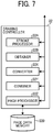
- FIG. 7 illustrates a functional configuration of the drawing controller 22 according to an embodiment.
- the drawing controller 22 includes a stroke processor 22A, an obtainer 22B, a converter 22X, a combiner 22Y, and a page processor 22Z.
- the stroke processor 22A which may be implemented by the instructions of the CPU 201, generates stroke data that reflects the user's drawing on the display 3 with the electronic pen 4 or the user's hand H. More specifically, the stroke data may be a stroke of a character, mark, or any other drawing, which may be drawn by the user. As described below referring to tables 1 to 4, in this disclosure, the stroke corresponds to a drawing made by a user with a single unbroken movement, for example, with the electronic pen.
- the obtainer 22B which may be implemented by the instructions of the CPU 201, obtains data stored in the memory 2000.
- the converter 22X which may be implemented by the instructions of the CPU 201, converts various data. For example, the converter 22X performs textization, real (binary) data conversion, serialization, deserialization, encoding, and decoding.
- the combiner 22Y which may be implemented by the instructions of the CPU 201, generates an image layer based on each type of data, and cause those image layers to be superimposed one above the other.
- image data types include a user interface (UI) data, stroke data, medium data (display data), background image data, and object data.
- UI data is used for generating a user interface, which includes, for example, a message for display to the user and an icon for selection by the user.
- the background image data is used for generating a background image, such as a frame to be used for defining a layout of the image.
- the stroked data, the medium data, and the object data are described below in detail.
- the page processor 22Z which may be implemented by the instructions of the CPU 201, associates the stroke data and the display data for the same one page, and stores this set of stroke data and display data in a page data memory 220 of the memory 2000.
- the page data memory 220 is a memory area of the memory 2000, which stores page data as illustrated in Table 1.
- Table 1 illustrates an example data structure of page data.
- the page data includes one-page data to be displayed on the display 2, which includes stroke arrangement data (items of stroke data for one character, etc.), and medium data as an example of display data.
- the page data includes a page data ID for identifying a specific page, start time when display of that page is started, end time when drawing to that page by a stroke drawing or a gesture is stopped, a stroke arrangement data ID for identifying stroke arrangement data, and a medium data ID for identifying medium data.
- the stroke arrangement data is to be used for displaying a set of stroke drawings on the display 3, as the stroke drawings are made by the user with the electronic pen 4 or the user's hand H.
- the medium data is to be used for displaying the other image (referred to as the display data) on the display 3, together with the stroke drawing.
- the stroke arrangement data includes various information as illustrated in Table 2 ( FIG. 14A ).
- Table 2 illustrates an example data structure of stroke arrangement data.
- one stroke arrangement data identified with the stroke arrangement data ID in Table 1, includes a plurality of items of stroke data, each corresponding to one stroke drawing.
- Each stroke data includes a stroke data ID for identifying that stroke data, start time when drawing of that stroke starts, end time when drawing of that stroke ends, a color of the stroke, a width of the stroke, and a coordinate arrangement data ID for identifying arrangement of points of the stroke.
- one stroke data ID is assigned to that stroke drawing "S”.
- two stroke data IDs are assigned to those two stroke drawings "T”.
- the coordinate arrangement data includes various information as illustrated in Table 3 ( FIG. 14B ).
- Table 3 illustrates an example data structure of the coordinate arrangement data.
- the coordinate arrangement data includes a single point (X coordinate value, Y coordinate value) on the display 3, difference time (ms) indicating a difference between the time when that point is drawn and the start time when drawing of the stroke starts, and pressure by the electronic pen 4 on that single point. That is, one item of coordinate arrangement data in Table 2 is a collection of single points in Table 3. For example, in case the user draws the alphabet "S" with the electronic pen 4 in one stroke, a plurality of points will be drawn, such that the coordinate arrangement data assigned with a specific data ID (such as, c001) corresponds to those points in the stroke drawing that are managed with Table 3.
- a specific data ID such as, c001
- the medium data of the page data in Table 1 includes various information as illustrated in Table 4.
- Table 4 illustrates an example data structure of medium data.
- the medium data includes a medium data ID for identifying the medium data as managed with Table 1, a type of the medium data, recording time when the medium data is recorded, a position of an image to be displayed on the display 3 based on the medium data (X coordinate, Y coordinate), a size of the image (width, height), and data indicating content of the medium data.
- the position of the image to be displayed based on the medium data is defined by the upper left corner of that image, when the X and Y coordinates of the upper left corner of the display 3 are set to (0, 0).
- the server 90 includes a communication controller 91.
- the communication controller 91 which may be implemented by the instructions of the CPU 201, controls communication with the communication controller 21 of the client 20.
- the client 20 may be the client 20 in the same electronic whiteboard 2, or the client 20 in the external electronic whiteboard 2 that is communicable via the first communication network 9a.
- the communication controller 81 of the client 80 which may be implemented by the instructions of the CPU 201 or 801, and the network controller 205 or the network I/F 811, controls communication with the communication controller 81 of the client 80 in the external electronic whiteboard 2, or the communication controller 51 of the management system 50.
- the display controller 82 of the client 80 is implemented by the instructions from the CPU 801, which is generated with activation of the communication application B11.
- the display controller 82 performs image processing based on data obtained from the communication controller 21 or the memory 8000, and controls output of processed image data.
- the management system 50 includes the hardware of FIG. 3 , which operates in cooperation with the control program, to implement the functional configuration of FIG. 6 .
- the management system 50 further includes a memory 5000, which may be implemented by the HD 504.
- the communication controller 51 of the management system 50 which may be implemented by the instructions of the CPU 501, controls communication with the communication controller 81 of the client 80 in the electronic whiteboard 2 or the PC 8.
- the first communication application A11 is activated to start processing by the client 20 of the electronic whiteboard 2a (S1).
- the communication controller 21 of the client 20 transmits an instruction to start processing by the server 90, to the communication controller 91 of the server 90 in the same electronic whiteboard 2a. Accordingly, the electronic whiteboard 2a is able to start various processing by the server 90, in addition to processing by the client 20 (S2).
- the communication controller 91 of the electronic whiteboard 2a generates connection data to be used for establishing connection with the electronic whiteboard 2a.
- the client 20 causes the display 3a to display the generated connection data (S3).
- the connection data includes the IP address of the host terminal, and a pass code that is generated for the communication session to be established for image sharing.
- the pass code, which is generated, is stored in the memory 2000.
- the user at the electronic whiteboard 2a who now knows the connection data, informs the other users at the electronic whiteboards 2b and 2c of that connection data through telephone or electronic mail.
- the communication application A11 is activated to start processing of the client 20 in the electronic whiteboard 2b (S4).
- the communication application A11 is activated to start processing of the client 20 in the electronic whiteboard 2c (S5).
- the communication controller 21 of the client 20 in the electronic whiteboard 2b transmits a participation request, with the pass code, to the communication controller 91 of the server 90 in the electronic whiteboard 2a (S6).
- the electronic whiteboard 2c transmits a participation request, with the pass code, to the electronic whiteboard 2a (S7).
- the communication controller 91 of the electronic whiteboard 2a receives the participation requests (with the pass code), respectively, from the electronic whiteboards 2b and 2c.
- the communication controller 91 authenticates the electronic whiteboards 2b and 2c, based on a match between the pass codes that are received from the electronic whiteboards 2b and 2c, and the pass code stored in the memory 2000 (S8).
- the communication controller 91 transmits authentication results to the clients 90 of the electronic whiteboards 2b and 2c (S9, S10).
- the electronic whiteboard 2a that operates as the host terminal establishes a communication, respectively, with the electronic whiteboard 2b and electronic whiteboard 2c that operate as participant terminals (S11, S12).
- content data transmitted among the electronic whiteboards 2a, 2b, and 2c include stroke data.
- FIG. 13B is an example screen 140 to be shared, displayed at the electronic whiteboard 2c.
- the drawing controller 20 of the client 20 in the electronic whiteboard 2c displays, as a part of the screen 140 that accepts drawing from the user, an icon 140i to be selected for activating the communication application B10.
- the client 20 of the electronic whiteboard 2c activates the communication application B10 to start processing by the client 80.
- the communication controller 81 of the client 80 transmits a login request to the management system 50 through the second communication network 9b (S22).
- the management system 50 receives the login request.
- the management system 50 authenticates the electronic whiteboard 2c that requests for log in (S23).
- the management system 50 transmits an authentication result to the electronic whiteboard 2c (S24).
- the communication controller 81 of the electronic whiteboard 2c receives the authentication result. In the following, it is assumed that the authentication result indicates that the electronic whiteboard 2c is allowed for log in.
- the communication application B11 As the PC 8 receives a request for activating the communication application B11, by a user input through the keyboard 821 or the mouse 822, the communication application B11 is activated to start processing by the client 80 of the PC 8 (S31).
- the communication controller 81 of the client 80 transmits a login request to the management system 50 through the second communication network 9b (S32).
- the management system 50 receives the login request.
- the management system 50 authenticates the PC 8 that requests for log in (S33).
- the management system 50 transmits an authentication result to the PC 8 (S34). In the following, it is assumed that the authentication result indicates that the PC 8 is allowed for log in.
- the communication controller 81 of the electronic whiteboard 2c transmits a request for starting communication (S41).
- the communication start request includes a contact ID for identifying the electronic whiteboard 2c that sends the communication start request, and a contact ID for identifying the PC 8 as a communication destination.
- the management system 50 receives the communication start request.
- the contact ID is any information that identifies a communication destination, which includes identification information identifying the communication terminal such as a terminal ID, and identification information identifying a user operating the communication terminal such as a user account.
- the management system 50 transmits a communication start request to the PC 8 (S42).
- the communication start request includes the contact ID for identifying the electronic whiteboard 2c as the communication start requester, and the contact ID for identifying the PC 8 as the communication destination, which are transmitted at S41.
- the PC 8 receives the communication start request.
- the communication controller 81 of the PC 8 transmits a response to the communication start request, to the management system 50 (S43). In the following, it is assumed that the PC 8 transmits a response indicating to accept the communication start request, to the management system 50.
- the management system 50 receives the response indicating to accept the communication start request.
- the management system 50 transmits, to the electronic whiteboard 2c that is the communication start requester, the response that is received from the PC 8 at S43 (S44).
- the communication controller 81 of the electronic whiteboard 2c receives the response accepting the communication start request.
- the management system 50 establishes a communication session between the electronic whiteboard 2c and the PC 8, through the second communication network 9b, to transmit or receive content data (S45).
- the content data may be shared in various ways.
- the management system 50 may set a specific destination that can be accessed by the electronic whiteboard 2c and the PC 8, which are authorized, to share content data.
- the destination for access may be set, within the management system 50 or any communication terminal other than the management system 50.
- the electronic whiteboard 2c and the PC 8 may each store content data to be shared at the specific destination, or obtain content data to be shared from the specific destination.
- the electronic whiteboard 2c and the PC 8 can exchange content data (S46).
- the content data to be transmitted between the electronic whiteboard 2c and the PC 8 includes display data, such as display data to be used for videoconference, which may be a video image or a still image, and stroke data such as a drawing image drawn by the user at the electronic whiteboard 2.
- display data such as display data to be used for videoconference, which may be a video image or a still image
- stroke data such as a drawing image drawn by the user at the electronic whiteboard 2.
- the stroke processor 22A As the user at the electronic whiteboard 2c draws a stroke image on the electronic whiteboard 2c with the electronic pen 4c, the stroke processor 22A generates stroke data based on the coordinate indicating the contact portion on the display 3c with the electronic pen 4c (S61).
- the stroke data includes a plurality of parameters as described referring to Table 2.
- the converter 22X groups a plurality of items of stroke data each reflecting one stroke drawing, and serializes the group of stroke data (S62).
- the communication controller 21 of the electronic whiteboard 2c transmits the serialized stroke data to the communication controller 91 of the electronic whiteboard 2a that is the host terminal, through the first communication network 9a (S63).
- the electronic whiteboard 2c may transmit stroke data reflecting one stroke drawing, one stroke drawing by one stroke drawing, to the electronic whiteboard 2a as the host terminal, as the stroke drawing is detected. For example, in case the user draws the alphabet "T", the electronic whiteboard 2c may transmit two items of stroke data, one drawing by one drawing.
- the communication controller 91 of the electronic whiteboard 2a transmits the received serialized stroke data to the client 20 of the electronic whiteboard 2a.
- the communication controller 21 of the client 20 in the electronic whiteboard 2a then receives the transmitted serialized stroke data.
- the converter 22X of the drawing controller 22 of the client 20 de-serializes the serialized stroke data (S64).
- the page processor 22Z stores the de-serialized stroke data in the page data memory 220, as newly-obtained stroke data to be added to previously stored stroke data.
- the combiner 22Y generates a stroke image, that is, a group of stroke drawings, based on the stroke data stored in the page data memory 220.
- the combiner 22Y further generates an output image, by combining items of object data stored in the page data memory 220.
- the combiner 22Y combines the generated output image, the generated stroke image, a user interface (UI) image, and a background image stored in the page data memory 220, to generate a combined image having four layers superimposed one above the other.
- the UI image may be previously stored in the page data memory 220.
- the combiner 22Y transmits the combined image to the display 3a for display at the display 3a (S65).
- FIG. 13A is an example of combined image having four image layers superimposed one above the other
- FIG. 13B is an example of combined image when displayed on a screen. As illustrated in FIG. 13A , the UI image layer 140a, the stroke image layer 140b, the output image layer 140c, and the background image layer 140d are superimposed one above the other to be displayed as a combined image.
- the communication controller 91 of the electronic whiteboard 2a transmits the serialized stroke data, transmitted from the electronic whiteboard 2c, to the clients 20 of the electronic whiteboards 2b and 2c, respectively (S66, S67).
- the communication controller 21 of the client 20 in each one of the electronic whiteboards 2b and 2c receives the transmitted stroke data.
- the client 20 in each of the electronic whiteboards 2b and 2c causes each one of the displays 3b and 3c to display the combined image, which includes the stroke image transmitted from the electronic whiteboard 2a. Since this operation is substantially similar to the operation described above referring to S64 to S65 for the case of the client 20 of the electronic whiteboard 2a, description thereof is omitted (S68 to S71).
- the communication controller 81 of the client 80 in the electronic whiteboard 2c obtains the combined image, which is transmitted from the combiner 22Y to the display 3c at S71 (S72).
- the combined image may be obtained at any desired time, such as every time the combined image is generated based on the stroke image being received at S67, or every predetermined time.
- the communication controller 81 of the electronic whiteboard 2c transmits the obtained combined image, as frame data of display data to the management system 50, through the communication session established between the communication controller 81 of the electronic whiteboard 2c and the communication controller 51 of the management system 50.
- the communication controller 51 of the management system 50 stores the received display data in the memory 5000.
- the communication controller 81 of the PC 8 obtains the display data from the management system 50, through the communication session established between the communication controller 81 of the PC 8 and the communication controller 51 of the management system 50. Accordingly, the electronic whiteboard 2c and the PC 8 share the display data (S73).
- the display controller 82 of the client 80 in the PC 8 displays the obtained display data, on the display 820 (S74).
- the electronic whiteboard 2 transmits the stroke data, for example, by one stroke by one stroke, as one stroke drawing is detected, to the counterpart electronic whiteboard 2 capable of processing stroke data for processing (S63, S66).
- the counterpart electronic whiteboard 2 stores the received stroke data in addition to previously stored stroke data, and generates a stroke image based on the accumulated items of stroke data.
- the electronic whiteboard 2 transmits the combined image to the management system 50 (S73), after the combined image is generated for display (S71).
- the management system 50 which is not capable of processing stroke data, is able to store the combined image including the stroke image, for example, for transmission to any desired apparatus that requests for sharing of image.
- the management system 50 transmits the combined image including the stroke image to the PC 8 for display at the PC 8, which is not capable of processing the stroke data.
- the electronic whiteboard 2 may transmit, to the counterpart electronic whiteboard 2, one item of stroke data identified with the stroke data ID s001, which is a group of points as illustrated in Table 3.
- the counterpart electronic whiteboard 2 stores the received stroke data together with previously stored stroke data for display as a stroke image.
- the electronic whiteboard 2 generates a stroke image based on the stroke arrangement data, which includes a plurality of strokes for one character, for example, and transmits the stroke image to the management system 50 as a part of the combined image.
- the above-described operation of controlling display of display data may be performed in various other ways.
- the following describes some modified examples.
- the electronic whiteboard 2 may be configured such that it is capable of performing operation, according to any one of the above-described example and the following modified examples.
- the electronic whiteboard 2c receives a request for adding or deleting an object.
- the object data include, but not limited to, information indicating a type of figure such as line, circle, polygon, arrow, etc., and information indicating a location of a side, center, or vertex of the figure, or any other information that may be utilized in drawing a specific object.
- the user is able to draw a flowchart using the objects, which may be selected from a menu that may be displayed on the electronic whiteboard 2c.
- the stroke processor 22A As the user at the electronic whiteboard 2c adds an object on the electronic whiteboard 2c with the electronic pen 4c, the stroke processor 22A generates object data based on the coordinate indicating the contact portion on the display 3b with the electronic pen 4b (S61A).
- the converter 22X serializes the object data (S62A) into a sequence of bytes.
- the communication controller 21 of the electronic whiteboard 2c transmits the serialized object data to the communication controller 91 of the electronic whiteboard 2a that is the host terminal (S63A).
- the communication controller 91 of the electronic whiteboard 2a transmits the received object data to the client 20 of the electronic whiteboard 2a.
- the communication controller 21 of the client 20 in the electronic whiteboard 2a receives the serialized object data.
- the converter 22X of the drawing controller 22 of the client 20 de-serializes the serialized object data (S64A).
- the page processor 22Z stores the de-serialized object data in the page data memory 220, as newly obtained object data to be added to previously stored object data.
- the combiner 22Y generates an output image, by combining the items of object data stored in the page data memory 220.
- the combiner 22Y further generates a stroke image, that is, a group of strokes, based on the stroke data stored in the page data memory 220.
- the combiner 22Y combines the generated output image, the generated stroke image, a user interface (UI) image, and a background image stored in the page data memory 220, to generate a combined image having four layers superimposed one above the other.
- the UI image may be previously stored in the page data memory 220.
- the combiner 22Y transmits the combined image to the display 3a for display at the display 3a (S65A).
- the combined image may be an image having a plurality of image layers being superimposed one above the other as illustrated in FIG. 13A , which may be displayed as one image as illustrated in FIG. 13B .
- S66A to S74A are performed in a substantially similar manner as described above referring to S66 to S74, except that data to be processed is object data in alternative to stroke data, description thereof is omitted.
- the object image is generated at the electronic whiteboard 2c.
- operation is performed in a substantially similar manner as described above referring to S61A to S74A, except that operation is performed by the client 20 at the electronic whiteboard 2a or 2b.
- the electronic whiteboard 2c receives a request for changing (adding or deleting) a background image.
- requests for changing the background image include, but not limited to, a request for obtaining a new background image to be replaced with the currently-displayed background image.
- the electronic whiteboard 2c As the user at the electronic whiteboard 2c requests to obtain an image being displayed at the PC 8 as an external device, with the electronic pen 4c, the electronic whiteboard 2c obtains the image being displayed at the note PC 8 as a background image (SB1).
- the converter 22X of the electronic whiteboard 2c textizes the obtained image data (SB2).
- the obtained image data as the background image is converted to text data, which is the same format as that of the stroke data and the object data.
- the converter 22X of the electronic whiteboard 2c serializes the image data, which is the text data (S62B).
- the communication controller 21 of the electronic whiteboard 2c transmits the serialized image data, to the communication controller 91 of the electronic whiteboard 2a that is the host terminal (S63B).
- the communication controller 91 of the electronic whiteboard 2a transmits the received image data to the client 20 of the electronic whiteboard 2a.
- the communication controller 21 of the client 20 in the electronic whiteboard 2a then receives the transmitted image data.
- the converter 22X of the drawing controller 22 of the client 20 de-serializes the image data (S64B).
- the converter 22X of the drawing controller 22 of the client 20 converts the image data, which is the text data, to real data (SB3).
- the page processor 22Z which may be implemented by the instructions of the CPU 201, stores the image data, which is the real data, in the page data memory 220 of the memory 2000, as medium data (Table 4).
- the combiner 22Y generates a stroke image, that is, a group of stroke drawings, based on the stroke data stored in the page data memory 220.
- the combiner 22Y further generates an output image, by combining items of object data stored in the page data memory 220.
- the combiner 22Y combines the generated output image, the generated stroke image, a user interface (UI) image, and the background image stored in the page data memory 220, to generate a combined image having four layers superimposed one above the other.
- the UI image may be previously stored in the page data memory 220.
- the combiner 22Y transmits the combined image to the display 3a for display at the display 3a (S65B).
- the combined image may be an image having a plurality of image layers being superimposed one above the other as illustrated in FIG. 13A , which may be displayed as one image as illustrated in FIG. 13B .
- the communication controller 91 of the electronic whiteboard 2a transmits the serialized image data, transmitted from the electronic whiteboard 2c, to the clients 20 of the electronic whiteboards 2b and 2c, respectively (S66B, S67B).
- the communication controller 21 of the client 20 in the electronic whiteboards 2b and 2c each receive the transmitted image data.
- the client 20 in each of the electronic whiteboards 2b and 2c causes each one of the displays 3b and 3c to display the combined image, which includes the background image transmitted from the electronic whiteboard 2a.
- the combined image to be displayed is not limited to the image illustrated in FIG. 13A .
- the stroke image layer and the output image layer may be displayed in an order different that the order illustrated in FIG. 13A .
- the electronic whiteboard 2 communicates with the counterpart electronic whiteboard 2 capable of processing stroke data, and the management system 50 not capable of processing stroke data.
- the electronic whiteboard 2 stores, in the data memory 220, a plurality of items of stroke data each reflecting a stroke drawing made by the user at the electronic whiteboard 2.
- the electronic whiteboard 2 transmits the stroke data to the counterpart electronic whiteboard 2, for example, as one stroke drawing is detected.
- the electronic whiteboard 2 generates a stroke image based on the stroke data accumulated in the memory 220, and further transmits a combined image including the stroke image to the management system 50. Accordingly, the electronic whiteboard 2 is able to share the stroke image with the management system 50, even when the management system 50 is not provided with a function of processing stroke data.
- the management system 50 is able to further transmit such combined image to any other apparatus.
- the electronic whiteboard 2 stores, in the data memory 220, object data that may be input by the user at the electronic whiteboard 2.
- the electronic whiteboard 2 transmits the object data to the counterpart electronic whiteboard 2, for example, as one object is detected.
- the electronic whiteboard 2 generates a stroke image based on the stroke data accumulated in the memory 220, and an output image superimposed with an object image generated based on the stored object data.
- the electronic whiteboard 2 further transmits a combined image including the stroke image and the output image to the management system 50. Accordingly, the electronic whiteboard 2 is able to share the object image with the management system 50, even when the management system 50 is not provided with a function of processing object data.
- the electronic whiteboard 2 obtains a background image from an external apparatus such as a PC, and stores the background image in the page data memory 220, in response to a user instruction.
- the electronic whiteboard 2 transmits the obtained background image to the counterpart electronic whiteboard 2.
- the electronic whiteboard 2 generates a stroke image based on the stroke data accumulated in the memory 220, and generates a combined image including the stroke image and the stored background image for transmission to the management system 50. Accordingly, the electronic whiteboard 2 is able to share the object image with the management system 50, even when the management system 50 is not provided with a function of managing a background image.
- the electronic whiteboard 2 may store the UI image.
- the UI image may be transmitted to the management system 50, as a part of the combined image.
- the management system 50 further transmits the combined image, which is transmitted from the electronic whiteboard 2, to the PC 8. Accordingly, even when the PC 8 is not capable of processing stroke data, the PC 8 is able to share the combined image including the stroke image with the electronic whiteboard 2.
- the communication applications A11, B10, and B11 may each be recorded in a file in a format installable or executable on a computer-readable recording medium for distribution.
- Examples of such recording medium include, but not limited to, compact disc-recordable (CD-R), digital versatile disc (DVD), and blue-ray disc.
- a memory storing any one of the above-described control programs such as a recording medium including a CD-ROM or a HDD, may be provided in the form of a program product to users within a certain country or outside that country.
- Any one of the electronic whiteboard 2, the PC 8, the relay device 30, and the management system 50 may be implemented as a single apparatus or a plurality of apparatuses to which divided portions (functions) are allocated.
- the electronic whiteboards 2 and the PC 8 are described as examples of apparatus capable of sharing images, however, any other apparatus can be used to share images. Examples of such apparatuses include, but not limited to, videoconference terminal, projector, digital signage, text sharing device, car navigation system, game machine, personal digital assistant (PDA), and remote diagnosis system.
- the present invention can be implemented in any convenient form, for example using dedicated hardware, or a mixture of dedicated hardware and software.
- the present invention may be implemented as computer software implemented by one or more networked processing apparatuses.
- the processing apparatuses can compromise any suitably programmed apparatuses such as a general purpose computer, personal digital assistant, mobile telephone (such as a WAP or 3G-compliant phone) and so on. Since the present invention can be implemented as software, each and every aspect of the present invention thus encompasses computer software implementable on a programmable device.
- the computer software can be provided to the programmable device using any conventional carrier medium (carrier means).
- the carrier medium can compromise a transient carrier medium such as an electrical, optical, microwave, acoustic or radio frequency signal carrying the computer code.
- transient medium is a TCP/IP signal carrying computer code over an IP network, such as the Internet.
- the carrier medium can also comprise a storage medium for storing processor readable code such as a floppy disk, hard disk, CD ROM, magnetic tape device or solid state memory device.
Abstract
Description
- The present invention relates to a communication terminal, a communication system, a communication control method, and carrier means.
- With the need for reducing costs or times associated with business trips, communication systems are widely used, which are capable of carrying out videoconferences among remotely located sites through a communication network such as the Internet. The communication systems enable transmission or reception of content data among a plurality of communication terminals. The content data may be display data such as an image of a videoconference participant or an image of presentation material, and stroke data reflecting drawings made by the participant.
- For example, as described in
Japanese Patent Application Publication No. 2015-70345-A1 - Example embodiments of the present invention include a communication terminal including a drawing controller that displays an image being shared with a first communication terminal and a second communication terminal, the image having a plurality of image layers superimposed one above the other. In response to a user input for changing appearance of a first image layer of the image, the drawing controller stores information reflecting the change caused by the user input to the first image layer in a memory, and generates an updated image having the first image layer that reflects the change caused by the user input, based on the information reflecting the change caused by the user input to the first image layer. The communication terminal further includes a first communication controller to transmit the information reflecting the change to the first image layer to the first communication terminal to cause the first communication terminal to generate and display the updated image, and a second communication controller to transmit the updated image having the first image layer that reflects the change to the second communication terminal to cause the second communication terminal to store the updated image.
- Example embodiments of the present invention include a communication system including the above-described communication terminal, the first communication terminal, and the second communication terminal. The second communication terminal may be a communication management server that controls communication among a plurality of communication terminals.
- Example embodiments of the present invention include a method of controlling sharing of an image, and carrier means such as a recording medium storing a program for controlling sharing of an image.
- With the above configuration, the communication terminal is able to share the image including the stroke image with any other communication terminal that is not capable of processing the stroke image.
- A more complete appreciation of the disclosure and many of the attendant advantages and features thereof can be readily obtained and understood from the following detailed description with reference to the accompanying drawings, wherein:
-
FIG. 1 is a schematic diagram illustrating a communication system according to an example embodiment of the present invention; -
FIG. 2 is a schematic block diagram illustrating a hardware configuration of an electronic whiteboard of the communication system ofFIG. 1 ; -
FIG. 3 is a schematic block diagram illustrating a hardware configuration of a communication management system of the communication system ofFIG. 1 ; -
FIG. 4 is a schematic block diagram illustrating a hardware configuration of a personal computer (PC) operating as a videoconference terminal, according to an embodiment of the present invention; -
FIG. 5A is a schematic block diagram illustrating a software configuration of the electronic whiteboard ofFIG. 2 , according to an embodiment of the present invention; -
FIG. 5B is a schematic block diagram illustrating a software configuration of the PC ofFIG. 4 , according to an embodiment of the present invention; -
FIG. 6 is a schematic block diagram illustrating a functional configuration of the electronic whiteboard, the PC, and the communication management system of the communication system ofFIG. 1 ; -
FIG. 7 is a schematic block diagram illustrating a drawing controller of the electronic whiteboard ofFIG. 5A , according to an embodiment of the present invention; -
FIG. 8 is a data sequence diagram illustrating operation of establishing communication among the electronic whiteboards ofFIG. 1 , according to an embodiment of the present invention; -
FIG. 9 is a data sequence diagram illustrating operation of establishing communication between the electronic whiteboard and the PC ofFIG. 1 , according to an embodiment of the present invention; -
FIG. 10 is a data sequence diagram illustrating operation of processing various image data for output through the electronic whiteboards, in response to detection of a stroke drawing, according to an embodiment of the present invention; -
FIG. 11 is a data sequence diagram illustrating operation of processing various image data for output through the electronic whiteboards, in response to detection of an object drawing, according to an embodiment of the present invention; -
FIG. 12 is a data sequence diagram illustrating operation of processing various image data for output through the electronic whiteboards, in response to a request for changing a background image, according to an embodiment of the present invention; -
FIG. 13A is an example of combined image having image layers superimposed one above the other; -
FIG. 13B is an example of combined image displayed at the electronic whiteboard or the PC; -
FIG. 14A andFIG. 14B are examples of table managed by the electronic whiteboard of the communication system ofFIG. 1 . - The accompanying drawings are intended to depict embodiments of the present invention and should not be interpreted to limit the scope thereof. The accompanying drawings are not to be considered as drawn to scale unless explicitly noted.
- The terminology used herein is for the purpose of describing particular embodiments only and is not intended to be limiting of the present invention. As used herein, the singular forms "a", "an" and "the" are intended to include the plural forms as well, unless the context clearly indicates otherwise.
- In describing embodiments illustrated in the drawings, specific terminology is employed for the sake of clarity. However, the disclosure of this specification is not intended to be limited to the specific terminology so selected and it is to be understood that each specific element includes all technical equivalents that have a similar function, operate in a similar manner, and achieve a similar result.
- Referring to the drawings, embodiments of the present invention are described.
- Referring to
FIG. 1 , a configuration of acommunication system 1 is described according to an embodiment.FIG. 1 is a schematic diagram illustrating thecommunication system 1 according to the embodiment. - The
communication system 1 includes a plurality of electronicwhite boards relay device 30, and acommunication management system 50. - The
electronic whiteboards first communication network 9a to be communicable with one another. Theelectronic whiteboards displays - The
electronic whiteboards displays electronic pens electronic whiteboards electronic whiteboard 2. Similarly, any arbitrary one of thedisplays display 3. Any arbitrary one of theelectronic pens electronic whiteboard 2 may change the drawing image being displayed on thedisplay 3, according to an event made by the user's hand H. For example, in response to the user's gesture indicating size enlargement, size reduction, or turning pages, theelectronic whiteboard 2 changes the image size or switches a screen. For simplicity, any arbitrary one of theelectronic whiteboards electronic whiteboard 2. Similarly, any arbitrary one of thedisplays display 3. Any arbitrary one of theelectronic pens - The
electronic whiteboards memories electronic whiteboards USB memories electronic whiteboards PCs USB memories note PCs note PC 6. - The stroke data, which is the drawing drawn on the
display 3 of theelectronic whiteboard 2, captured at a first site is transmitted to a second site through thefirst communication network 9a for output through thedisplay 3 of theelectronic whiteboard 2 at the second site. Similarly, the stroke data, which is the drawing drawn on thedisplay 3 of theelectronic whiteboard 2 at the second site, is transmitted to the first site through thefirst communication network 9a for output through thedisplay 3 of theelectronic whiteboard 2 at the first site. As described above, the drawing images can be shared among remotely located sites, such that thecommunication system 1 with theelectronic whiteboards 2 can facilitate communication in a videoconference. - In addition to the
electronic whiteboard 2, the drawings, such as stroke data, can be shared by any desired communication terminal connected to thefirst communication network 9a. Examples of such communication terminal include, PC, videoconference terminal, tablet, smart phone, digital signage, telestrator, image processing apparatus, portable information processing device, digital video camera, digital still camera, and game machine. The telestrator may be used for providing information on sports or weather. The image processing apparatus may be used to provide a remote medical diagnosis system. The game machine may be one example of any terminal capable of providing a frame of image data. - The
electronic whiteboard 2c, thePC 8, and themanagement system 50 are connected via asecond communication network 9b to be communicable with one another. - The
electronic whiteboard 2c and thePC 8 communicate with each other to transmit or receive display data, such as image data for videoconferencing, as an example of content data. The display data is any image data that can be displayed on a display, such as an image captured at one site during videoconference. More specifically, the display data may be a video image or a still image, or both of the video image and the still image. - The
management system 50 centrally manages communicates states of theelectronic whiteboard 2c and thePC 8. - While the
electronic whiteboard 2c and thePC 8 are connected to thesecond communication network 9b in this example, any other communication terminal may be connected to thesecond communication network 9b to share display data with theelectronic whiteboard 2c and thePC 8. Examples of such communication terminal include, but not limited to, videoconference terminal, tablet, smart phone, digital signage, telestrator, image processing apparatus, portable information processing terminal, digital video camera, digital still camera, and game machine. - In this embodiment, the
electronic whiteboard 2c activates a module for sharing stroke data, and a module for sharing display data, to share stroke data and display data among the communication terminals. - In one example, the
first communication network 9a is the Intranet, and thesecond communication network 9b is the Internet. Thecommunication networks communication system 1, and may be selected from the Internet, local area network (LAN), the Intranet, and mobile phone network. Thecommunication networks - The example illustrated in
FIG. 1 uses the USB memory 5 as a memory attachable to theelectronic whiteboard 2, however, any desired memory may be used such as a SD card. -
FIG. 2 illustrates a hardware configuration of theelectronic whiteboard 2, according to the embodiment.FIG. 2 is a schematic block diagram illustrating a hardware configuration of theelectronic whiteboard 2 illustrated inFIG. 1 . - As illustrated in
FIG. 2 , theelectronic whiteboard 2 includes a central processing unit (CPU) 201 that controls entire operation of theelectronic whiteboard 2, a read only memory (ROM) 202 that stores a program for operating theCPU 201 such as an initial program loader (IPL), a random access memory (RAM) 203 that operates as a work area for theCPU 201, a solid state drive (SSD) 204 that controls reading or writing of various types of data including control program stored in a memory, anetwork controller 205 that controls communication via thecommunication network external memory controller 206 that controls communication with the USB memory 5. Theelectronic whiteboard 2 further includes acamera 207 that captures an object under control of theCPU 201, an imaging element I/F 208 that controls operation of thecamera 207, acapture device 211 that transmits image data (still or moving image) for display at thenote PC 6, a graphics processing unit (GPU) 212 that processing graphics, and adisplay controller 213 that controls transmission of image data output from theGPU 212 to thedisplay 3. Theelectronic whiteboard 2 further includes asensor controller 214 and acontact sensor 215. Thesensor controller 214 controls operation of thecontact sensor 215. The contact sensor 715 detects a touch onto thedisplay 3 with the electronic pen 4 or the user's hand H. In this example, thecontact sensor 215 senses a touch input to a specific coordinate on thedisplay 3 using the infrared blocking system. More specifically, thedisplay 3 is provided with two light receiving elements disposed on both upper side ends of thedisplay 3, and a reflector frame. The light receiving elements emit a plurality of infrared rays in parallel to a touch panel of thedisplay 3. The light receiving elements receive lights passing in the direction that is the same as an optical path of the emitted infrared rays, which are reflected by the reflector frame. Thecontact sensor 215 outputs an identifier (ID) of the infrared ray that is blocked by an object (such as the user's hand) after being emitted from the light receiving elements, to thesensor controller 214. Based on the ID of the infrared ray, thesensor controller 214 detects a specific coordinate that is touched. - The
contact sensor 215 is not limited to the infrared blocking system type, and may be a different type of detector, such as a capacitance touch panel that identifies the contact position by detecting a change in capacitance, a resistance film touch panel that identifies the contact position by detecting a change in voltage of two opposed resistance films, or an electromagnetic induction touch panel that identifies the contact position by detecting electromagnetic induction caused by contact of an object to a display. Alternatively, thecontact sensor 215 may identify the contact position using thecamera 207. - The
electronic whiteboard 2 further includes anelectronic pen controller 216. Theelectronic pen controller 216 communicates with the electronic pen 4 to detect a touch by the tip or bottom of the pen 4 to thedisplay 3. In addition or in alternative to detecting a touch by the tip or bottom of the pen 4, theelectronic pen controller 216 may also detect a touch by another part of the electronic pen 4, such as a part held by a hand. - The
electronic whiteboard 2 further includes amicrophone 222 that inputs audio, aspeaker 223 that outputs audio, an audio input/output I/F 224 that processes input or output of audio signals between themicrophone 222 and thespeaker 223 under control of theCPU 201, operation key(s) 225 that receives user inputs, and apower switch 226 that turns on or off the electronic power of theelectronic whiteboard 2. - The
electronic whiteboard 2 further includes abus line 230, such as an address bus or a data bus, which electrically connects the elements illustrated inFIG. 2 . The control program for theelectronic whiteboard 2 may be stored on a computer-readable recording medium such as a CD-ROM for distribution, or stored on a server on any desired network to be downloaded. - Referring to
FIG. 3 , a hardware configuration of thecommunication management system 50 is described according to an embodiment of the present invention.FIG. 3 is a schematic block diagram illustrating a hardware configuration of thecommunication management system 50 according to the embodiment. - The
management system 50 includes aCPU 501 that controls entire operation of themanagement system 50, aROM 502 that stores a communication control program, aRAM 503 that operates as a work area for theCPU 501, a hard disk (HD) 504 that stores various data, aHDD 505 that controls reading or writing of various data from or to theHD 504 under control of theCPU 501, and a medium I/F 507 that controls reading or writing of data with respect to arecording medium 506 such as a flash memory. Themanagement system 50 further includes a display I/F 508 that displays various information on adisplay 516 such as a curser, menu, window, character, or image, a network I/F 509 that controls transmission of data through thecommunication network keyboard 511 provided with a plurality of keys for inputting a character, numeral, or instruction, and amouse 512 that selects or executes an instruction through selection of a processing target or movement of a mouse curser. Themanagement system 50 further includes a CD-ROM drive 514 that controls reading or writing with respect to a CD-ROM 513 as an example of removable memory, an external device I/F 515 that controls transmission of various data with an external device, and abus line 510, such as an address bus or a data bus, that electrically connects the elements illustrated inFIG. 3 . - Note that the communication control program may be recorded in a file in a format installable or executable on a computer-readable recording medium such as the
recording medium 506 or the CD-ROM 513 for distribution. The communication control program may be stored on theHD 504. -
FIG. 4 illustrates a hardware configuration of thePC 8, as an example of videoconference terminal, according to the embodiment. ThePC 8 includes a central processing unit (CPU) 801, a read only memory (ROM) 802, a random access memory (RAM) 803, aflash memory 804, a solid state drive (SSD) 805, a medium interface (I/F) 807, apower switch 809, abus line 810, a network I/F 811, acamera 812, animaging element 1/F 813, amicrophone 814, aspeaker 815, an audio input/output I/F 816, a display I/F 817, an external device I/F 818, akeyboard 821, and amouse 822. TheCPU 801 controls entire operation of thePC 8. TheROM 802 stores a control program for operating theCPU 801 such as an Initial Program Loader (IPL). TheRAM 803 is used as a work area for theCPU 801. Theflash memory 804 stores various data such as a communication control program, display data, and audio data. TheSSD 805 controls reading or writing of various data with respect to theflash memory 804 under control of theCPU 801. In alternative to the SSD, a hard disk drive (HDD) may be used. The medium I/F 807 controls reading or writing of data with respect to arecording medium 806 such as a flash memory. - The network I/
F 811 controls communication of data with an external device through thesecond communication network 9b. Thecamera 812 is an example of imaging device capable of capturing an object under control of theCPU 801, and is incorporated in thePC 8. Theimaging element 1/F 813 is a circuit that controls driving of thecamera 812. Themicrophone 814 is an example of audio collecting device capable of inputting audio under control of theCPU 801, and is incorporated in thePC 8. The audio I/O I/F 816 is a circuit for inputting or outputting an audio signal between themicrophone 814 and thespeaker 815 under control of theCPU 801. The display I/F 817 is a circuit for transmitting display data to theexternal display 820 under control of theCPU 801. The external device I/F 818 is an interface circuit that connects thePC 8 to various external devices. Thekeyboard 821 is one example of input device provided with a plurality of keys for allowing a user to input characters, numerals, or various instructions. Themouse 812 is one example of input device for allowing the user to select a specific instruction or execution, select a target for processing, or move a curser being displayed. - The
bus line 810 is an address bus or a data bus, which electrically connects the elements inFIG. 4 such as theCPU 801. - The
display 820 may be a liquid crystal or organic electroluminescence (EL) display that displays an image of a subject, an operation icon, or the like. Thedisplay 820 is connected to the display I/F 817 by acable 820c. Thecable 820c may be an analog red green blue (RGB) (video graphic array (VGA)) signal cable, a component video cable, a high-definition multimedia interface (HDMI) signal cable, or a digital video interactive (DVI) signal cable. - The
camera 812 includes a lens and a solid-state imaging element that converts an image (video) of a subject to electronic data by converting light to electric charge. As the solid-state imaging element, for example, a complementary metal-oxide-semiconductor (CMOS) or a charge-coupled device (CCD) is used. The external device I/F 818 is capable of connecting an external device such as an external camera, an external microphone, or an external speaker through a Universal Serial Bus (USB) cable or the like. In the case where an external camera is connected, the external camera is driven in preference to the built-incamera 812 under control of theCPU 801. Similarly, in the case where an external microphone is connected or an external speaker is connected, the external microphone or the external speaker is driven in preference to the built-inmicrophone 814 or the built-inspeaker 815 under control of theCPU 801. - The
recording medium 806 is removable from thePC 8. Therecording medium 801 can be any non-volatile memory that reads or writes data under control of theCPU 801, such that any memory such as an electrically erasable and programmable read-only memory (EEPROM) may be used instead of theflash memory 804. -
FIG. 5A is a schematic block diagram illustrating a software configuration of theelectronic whiteboard 2 ofFIG. 2 , according to an embodiment of the present invention. As illustrated inFIG. 5A , theelectronic whiteboard 2 is installed with an operating system (OS) 2020, first communication application A11, and second communication application B10, each of which operates on awork area 2010 of theRAM 203. - The
OS 2020 is basic software that controls entire operation of theelectronic whiteboard 2 through providing basic functions. The communication application A11 and B10 each enable theelectronic whiteboard 2 to communicate with the other electronic whiteboard (or communication terminal), using different communication protocols. The first communication application A11 provides theelectronic whiteboard 2 with a communication control function of controlling transmission of stroke data with the other communication terminal, and an image processing function of outputting stroke data as an image. The second communication application B10 provides theelectronic whiteboard 2 with a communication control function of controlling transmission of display data (such as image data for videoconferencing) with the other communication terminal, and an image processing function of outputting display data as an image. - The
OS 2020 and the first communication application A11 are installed onto theelectronic whiteboard 2 before shipment. The second communication application B10 may be installed onto theelectronic whiteboard 2, after shipment. In the following, it is assumed that theelectronic whiteboard 2c is installed with the second communication application B10, and theelectronic whiteboards -
FIG. 5B is a schematic block diagram illustrating a software configuration of thePC 8 ofFIG. 4 , according to an embodiment of the present invention. As illustrated inFIG. 5B , thePC 8 is installed with operating system (OS) 8020, and the third communication application B11, which may be deployed on a workingarea 8010 of theRAM 803. - The
OS 8020 is basic software that controls entire operation of thePC 8 through providing basic functions. The third communication application B11 provides thePC 8 with the communication control function of controlling transmission of display data with the other communication terminal, and the image processing function of outputting display data as an image. - The
OS 8020 and the third communication application B11 are installed onto thePC 8 before or after shipment. - Now, a functional configuration of the
communication system 1 is described according to an embodiment of the present invention.FIG. 6 is a schematic block diagram illustrating a functional configuration of theelectronic whiteboard 2, thePC 8, and themanagement system 50 of the communication system ofFIG. 1 . InFIG. 6 , theelectronic whiteboards first communication network 9a to transmit or receive data. Further, inFIG. 6 , theelectronic whiteboard 2c, thePC 8, and themanagement system 50 are connected through thesecond communication network 9b to transmit or receive data. - The
electronic whiteboard 2 includes hardware ofFIG. 2 , which operates in cooperation with the control program, to implement the functional configuration ofFIG. 6 . Theelectronic whiteboard 2 includes amemory 2000 implemented by theSSD 204. ThePC 8 includes the hardware ofFIG. 4 , which operates in cooperation with the control program, to implement the functional configuration ofFIG. 6 . ThePC 8 includes amemory 8000 implemented by theSSD 805. - The
electronic whiteboard 2 may function as a "host terminal" that requests to start communication to share images, or a "participant terminal" that participates in communication started by the host terminal. Theelectronic whiteboard 2 mainly includes a client section ("client") 20 and a server section ("server") 90. Theclient 20 and theserver 90 are functions performed by oneelectronic whiteboard 2, with activation of the first communication application A11. Alternatively, the electronic whiteboard two may only function as theclient 20, while causing other apparatus such as a distribution control apparatus to operate as theserver 90. - In case the
electronic whiteboard 2 operates as the host terminal, suchelectronic whiteboard 2 implements both of theclient 20 and theserver 90. In case theelectronic whiteboard 2 operates as the participant terminal, suchelectronic whiteboard 2 implements theclient 20 but not theserver 90. For example, in case theelectronic whiteboard 2a operates as the host terminal, and theelectronic whiteboards client 20 of theelectronic whiteboard 2a communicates with theclient 20 of each of theelectronic whiteboards server 90 in theelectronic whiteboard 2a. Theclient 20 of each one of theelectronic whiteboards client 20 of theelectronic whiteboard server 90 in theelectronic whiteboard 2a. - The
electronic whiteboard 2b and thePC 8 implement theclient 80, with activation of the second communication application B10 and the third communication application B 11, respectively. Theclient 80 communicates with theclient 80 of the other communication terminal through a communication session established based on a call control by themanagement system 50 operating as a server. - The
client 20 includes acommunication controller 21 and a drawingcontroller 22. Thecommunication controller 21, which may be implemented by the instructions of theCPU 201, or thenetwork controller 205, controls communication with the otherelectronic whiteboard 2 or acommunication controller 91 of theserver 90, through thefirst communication network 9a. - The drawing
controller 22, which may be implemented by the instructions of theCPU 201, performs image processing on stroke data that is generated in response to operation on thedisplay 3, or various data obtained from any desired device. Examples of such device include, but not limited to, the USB memory 5, thenote PC 6, thecommunication controller 21, and thememory 2000. The drawingcontroller 22 generates an image layer based on the processed image data, and controls output of a combined image on which a plurality of image layers are superimposed one above the other. -
FIG. 7 illustrates a functional configuration of the drawingcontroller 22 according to an embodiment. The drawingcontroller 22 includes a stroke processor 22A, an obtainer 22B, a converter 22X, a combiner 22Y, and apage processor 22Z. - The stroke processor 22A, which may be implemented by the instructions of the
CPU 201, generates stroke data that reflects the user's drawing on thedisplay 3 with the electronic pen 4 or the user's hand H. More specifically, the stroke data may be a stroke of a character, mark, or any other drawing, which may be drawn by the user. As described below referring to tables 1 to 4, in this disclosure, the stroke corresponds to a drawing made by a user with a single unbroken movement, for example, with the electronic pen. - The obtainer 22B, which may be implemented by the instructions of the
CPU 201, obtains data stored in thememory 2000. - The converter 22X, which may be implemented by the instructions of the
CPU 201, converts various data. For example, the converter 22X performs textization, real (binary) data conversion, serialization, deserialization, encoding, and decoding. - The combiner 22Y, which may be implemented by the instructions of the
CPU 201, generates an image layer based on each type of data, and cause those image layers to be superimposed one above the other. Examples of image data types include a user interface (UI) data, stroke data, medium data (display data), background image data, and object data. The UI data is used for generating a user interface, which includes, for example, a message for display to the user and an icon for selection by the user. The background image data is used for generating a background image, such as a frame to be used for defining a layout of the image. The stroked data, the medium data, and the object data are described below in detail. - The
page processor 22Z, which may be implemented by the instructions of theCPU 201, associates the stroke data and the display data for the same one page, and stores this set of stroke data and display data in apage data memory 220 of thememory 2000. - The
page data memory 220 is a memory area of thememory 2000, which stores page data as illustrated in Table 1. Table 1 illustrates an example data structure of page data. The page data includes one-page data to be displayed on thedisplay 2, which includes stroke arrangement data (items of stroke data for one character, etc.), and medium data as an example of display data.TABLE 1 PAGE DATA ID START TIME END TIME STROKE ARRANGEMENT DATA ID MEDIUM DATA ID S001 20150522152034 20150522152402 st001 m001 S002 20150522152415 2015522152825 st002 m002 S003 20150522153345 20150522154033 st003 m003 ··· ··· ··· ··· ··· - The page data includes a page data ID for identifying a specific page, start time when display of that page is started, end time when drawing to that page by a stroke drawing or a gesture is stopped, a stroke arrangement data ID for identifying stroke arrangement data, and a medium data ID for identifying medium data. The stroke arrangement data is to be used for displaying a set of stroke drawings on the
display 3, as the stroke drawings are made by the user with the electronic pen 4 or the user's hand H. The medium data is to be used for displaying the other image (referred to as the display data) on thedisplay 3, together with the stroke drawing. - The stroke arrangement data includes various information as illustrated in Table 2 (
FIG. 14A ). Table 2 illustrates an example data structure of stroke arrangement data. As illustrated in Table 2, one stroke arrangement data, identified with the stroke arrangement data ID in Table 1, includes a plurality of items of stroke data, each corresponding to one stroke drawing. Each stroke data includes a stroke data ID for identifying that stroke data, start time when drawing of that stroke starts, end time when drawing of that stroke ends, a color of the stroke, a width of the stroke, and a coordinate arrangement data ID for identifying arrangement of points of the stroke. For example, in case the user draws the alphabet "S" with the electronic pen 4 in one stroke, one stroke data ID is assigned to that stroke drawing "S". In case the user draws the alphabet "T" with the electronic pen 4 in two strokes, two stroke data IDs are assigned to those two stroke drawings "T". - The coordinate arrangement data includes various information as illustrated in Table 3 (
FIG. 14B ). Table 3 illustrates an example data structure of the coordinate arrangement data. The coordinate arrangement data includes a single point (X coordinate value, Y coordinate value) on thedisplay 3, difference time (ms) indicating a difference between the time when that point is drawn and the start time when drawing of the stroke starts, and pressure by the electronic pen 4 on that single point. That is, one item of coordinate arrangement data in Table 2 is a collection of single points in Table 3. For example, in case the user draws the alphabet "S" with the electronic pen 4 in one stroke, a plurality of points will be drawn, such that the coordinate arrangement data assigned with a specific data ID (such as, c001) corresponds to those points in the stroke drawing that are managed with Table 3. - The medium data of the page data in Table 1 includes various information as illustrated in Table 4. Table 4 illustrates an example data structure of medium data. As illustrated in Table 4, the medium data includes a medium data ID for identifying the medium data as managed with Table 1, a type of the medium data, recording time when the medium data is recorded, a position of an image to be displayed on the
display 3 based on the medium data (X coordinate, Y coordinate), a size of the image (width, height), and data indicating content of the medium data. The position of the image to be displayed based on the medium data is defined by the upper left corner of that image, when the X and Y coordinates of the upper left corner of thedisplay 3 are set to (0, 0).TABLE 4 MEDIUM DATA ID DATA TYPE RECORDING TIME X Y WIDTH HEIGHT DATA m001 IMAGE 20150522152632 1400 50 400 300 abc.jpg ··· ··· ··· ··· ··· ··· ··· ··· - Now, a functional configuration of the
server 90 is described. Theserver 90 includes acommunication controller 91. - The
communication controller 91, which may be implemented by the instructions of theCPU 201, controls communication with thecommunication controller 21 of theclient 20. As described above, theclient 20 may be theclient 20 in the sameelectronic whiteboard 2, or theclient 20 in the externalelectronic whiteboard 2 that is communicable via thefirst communication network 9a. - The
communication controller 81 of theclient 80, which may be implemented by the instructions of theCPU network controller 205 or the network I/F 811, controls communication with thecommunication controller 81 of theclient 80 in the externalelectronic whiteboard 2, or the communication controller 51 of themanagement system 50. - The
display controller 82 of theclient 80 is implemented by the instructions from theCPU 801, which is generated with activation of the communication application B11. Thedisplay controller 82 performs image processing based on data obtained from thecommunication controller 21 or thememory 8000, and controls output of processed image data. - The
management system 50 includes the hardware ofFIG. 3 , which operates in cooperation with the control program, to implement the functional configuration ofFIG. 6 . Themanagement system 50 further includes amemory 5000, which may be implemented by theHD 504. - The communication controller 51 of the
management system 50, which may be implemented by the instructions of theCPU 501, controls communication with thecommunication controller 81 of theclient 80 in theelectronic whiteboard 2 or thePC 8. - Referring now to
FIGs. 8 to 11 , operation of controlling display of various data is described according to an embodiment. - Referring to
FIG. 8 , operation of establishing communication among theelectronic whiteboards power switch 226 of theelectronic whiteboard 2a is turned on by the user, the first communication application A11 is activated to start processing by theclient 20 of theelectronic whiteboard 2a (S1). In response to receiving a request for starting a conference through operation onto thedisplay 3a, thecommunication controller 21 of theclient 20 transmits an instruction to start processing by theserver 90, to thecommunication controller 91 of theserver 90 in the sameelectronic whiteboard 2a. Accordingly, theelectronic whiteboard 2a is able to start various processing by theserver 90, in addition to processing by the client 20 (S2). - The
communication controller 91 of theelectronic whiteboard 2a generates connection data to be used for establishing connection with theelectronic whiteboard 2a. Theclient 20 causes thedisplay 3a to display the generated connection data (S3). The connection data includes the IP address of the host terminal, and a pass code that is generated for the communication session to be established for image sharing. The pass code, which is generated, is stored in thememory 2000. The user at theelectronic whiteboard 2a, who now knows the connection data, informs the other users at theelectronic whiteboards - As the user at the
electronic whiteboard 2b turns on thepower switch 226, the communication application A11 is activated to start processing of theclient 20 in theelectronic whiteboard 2b (S4). Similarly, as the user at theelectronic whiteboard 2c turns on thepower switch 226, the communication application A11 is activated to start processing of theclient 20 in theelectronic whiteboard 2c (S5). In response to a user input to thedisplay 3b that requests connection, thecommunication controller 21 of theclient 20 in theelectronic whiteboard 2b transmits a participation request, with the pass code, to thecommunication controller 91 of theserver 90 in theelectronic whiteboard 2a (S6). Similarly, theelectronic whiteboard 2c transmits a participation request, with the pass code, to theelectronic whiteboard 2a (S7). Thecommunication controller 91 of theelectronic whiteboard 2a receives the participation requests (with the pass code), respectively, from theelectronic whiteboards - Next, the
communication controller 91 authenticates theelectronic whiteboards electronic whiteboards communication controller 91 transmits authentication results to theclients 90 of theelectronic whiteboards electronic whiteboards electronic whiteboard 2a that operates as the host terminal establishes a communication, respectively, with theelectronic whiteboard 2b andelectronic whiteboard 2c that operate as participant terminals (S11, S12). In the following, it is assumed that content data transmitted among theelectronic whiteboards - Referring to
FIG. 9 , operation of establishing communication between theelectronic whiteboard 2c and thePC 8, with the communication applications B10 and B11, is described according to an embodiment. - In response to a user input to the
display 3c that requests activation, theclient 20 of theelectronic whiteboard 2c activates the communication application B10 to start processing by the client 80 (S21).FIG. 13B is anexample screen 140 to be shared, displayed at theelectronic whiteboard 2c. As illustrated inFIG. 13B , the drawingcontroller 20 of theclient 20 in theelectronic whiteboard 2c displays, as a part of thescreen 140 that accepts drawing from the user, anicon 140i to be selected for activating the communication application B10. In response to a user selection of theicon 140i, theclient 20 of theelectronic whiteboard 2c activates the communication application B10 to start processing by theclient 80. - The
communication controller 81 of theclient 80 transmits a login request to themanagement system 50 through thesecond communication network 9b (S22). Themanagement system 50 receives the login request. - The
management system 50 authenticates theelectronic whiteboard 2c that requests for log in (S23). Themanagement system 50 transmits an authentication result to theelectronic whiteboard 2c (S24). Thecommunication controller 81 of theelectronic whiteboard 2c receives the authentication result. In the following, it is assumed that the authentication result indicates that theelectronic whiteboard 2c is allowed for log in. - As the
PC 8 receives a request for activating the communication application B11, by a user input through thekeyboard 821 or themouse 822, the communication application B11 is activated to start processing by theclient 80 of the PC 8 (S31). - The
communication controller 81 of theclient 80 transmits a login request to themanagement system 50 through thesecond communication network 9b (S32). Themanagement system 50 receives the login request. - The
management system 50 authenticates thePC 8 that requests for log in (S33). Themanagement system 50 transmits an authentication result to the PC 8 (S34). In the following, it is assumed that the authentication result indicates that thePC 8 is allowed for log in. - In response to the user input to the
display 3, thecommunication controller 81 of theelectronic whiteboard 2c transmits a request for starting communication (S41). The communication start request includes a contact ID for identifying theelectronic whiteboard 2c that sends the communication start request, and a contact ID for identifying thePC 8 as a communication destination. Themanagement system 50 receives the communication start request. The contact ID is any information that identifies a communication destination, which includes identification information identifying the communication terminal such as a terminal ID, and identification information identifying a user operating the communication terminal such as a user account. - The
management system 50 transmits a communication start request to the PC 8 (S42). The communication start request includes the contact ID for identifying theelectronic whiteboard 2c as the communication start requester, and the contact ID for identifying thePC 8 as the communication destination, which are transmitted at S41. ThePC 8 receives the communication start request. - The
communication controller 81 of thePC 8 transmits a response to the communication start request, to the management system 50 (S43). In the following, it is assumed that thePC 8 transmits a response indicating to accept the communication start request, to themanagement system 50. - The
management system 50 receives the response indicating to accept the communication start request. Themanagement system 50 transmits, to theelectronic whiteboard 2c that is the communication start requester, the response that is received from thePC 8 at S43 (S44). Thecommunication controller 81 of theelectronic whiteboard 2c receives the response accepting the communication start request. - The
management system 50 establishes a communication session between theelectronic whiteboard 2c and thePC 8, through thesecond communication network 9b, to transmit or receive content data (S45). The content data may be shared in various ways. For example, themanagement system 50 may set a specific destination that can be accessed by theelectronic whiteboard 2c and thePC 8, which are authorized, to share content data. The destination for access may be set, within themanagement system 50 or any communication terminal other than themanagement system 50. Theelectronic whiteboard 2c and thePC 8 may each store content data to be shared at the specific destination, or obtain content data to be shared from the specific destination. - Through the established communication session, the
electronic whiteboard 2c and thePC 8 can exchange content data (S46). In this embodiment, the content data to be transmitted between theelectronic whiteboard 2c and thePC 8 includes display data, such as display data to be used for videoconference, which may be a video image or a still image, and stroke data such as a drawing image drawn by the user at theelectronic whiteboard 2. Referring toFIG. 10 , operation of outputting an image to be shared among theelectronic whiteboards 2 is described according to an embodiment. - As the user at the
electronic whiteboard 2c draws a stroke image on theelectronic whiteboard 2c with theelectronic pen 4c, the stroke processor 22A generates stroke data based on the coordinate indicating the contact portion on thedisplay 3c with theelectronic pen 4c (S61). The stroke data includes a plurality of parameters as described referring to Table 2. The converter 22X groups a plurality of items of stroke data each reflecting one stroke drawing, and serializes the group of stroke data (S62). Thecommunication controller 21 of theelectronic whiteboard 2c transmits the serialized stroke data to thecommunication controller 91 of theelectronic whiteboard 2a that is the host terminal, through thefirst communication network 9a (S63). Theelectronic whiteboard 2c may transmit stroke data reflecting one stroke drawing, one stroke drawing by one stroke drawing, to theelectronic whiteboard 2a as the host terminal, as the stroke drawing is detected. For example, in case the user draws the alphabet "T", theelectronic whiteboard 2c may transmit two items of stroke data, one drawing by one drawing. - As the serialized stroked data is received from the
electronic whiteboard 2c, thecommunication controller 91 of theelectronic whiteboard 2a transmits the received serialized stroke data to theclient 20 of theelectronic whiteboard 2a. Thecommunication controller 21 of theclient 20 in theelectronic whiteboard 2a then receives the transmitted serialized stroke data. The converter 22X of the drawingcontroller 22 of theclient 20 de-serializes the serialized stroke data (S64). Thepage processor 22Z stores the de-serialized stroke data in thepage data memory 220, as newly-obtained stroke data to be added to previously stored stroke data. The combiner 22Y generates a stroke image, that is, a group of stroke drawings, based on the stroke data stored in thepage data memory 220. The combiner 22Y further generates an output image, by combining items of object data stored in thepage data memory 220. The combiner 22Y combines the generated output image, the generated stroke image, a user interface (UI) image, and a background image stored in thepage data memory 220, to generate a combined image having four layers superimposed one above the other. The UI image may be previously stored in thepage data memory 220. The combiner 22Y transmits the combined image to thedisplay 3a for display at thedisplay 3a (S65).FIG. 13A is an example of combined image having four image layers superimposed one above the other, andFIG. 13B is an example of combined image when displayed on a screen. As illustrated inFIG. 13A , theUI image layer 140a, thestroke image layer 140b, theoutput image layer 140c, and thebackground image layer 140d are superimposed one above the other to be displayed as a combined image. - Referring back to
FIG. 10 , thecommunication controller 91 of theelectronic whiteboard 2a transmits the serialized stroke data, transmitted from theelectronic whiteboard 2c, to theclients 20 of theelectronic whiteboards communication controller 21 of theclient 20 in each one of theelectronic whiteboards client 20 in each of theelectronic whiteboards displays electronic whiteboard 2a. Since this operation is substantially similar to the operation described above referring to S64 to S65 for the case of theclient 20 of theelectronic whiteboard 2a, description thereof is omitted (S68 to S71). - The
communication controller 81 of theclient 80 in theelectronic whiteboard 2c obtains the combined image, which is transmitted from the combiner 22Y to thedisplay 3c at S71 (S72). The combined image may be obtained at any desired time, such as every time the combined image is generated based on the stroke image being received at S67, or every predetermined time. Thecommunication controller 81 of theelectronic whiteboard 2c transmits the obtained combined image, as frame data of display data to themanagement system 50, through the communication session established between thecommunication controller 81 of theelectronic whiteboard 2c and the communication controller 51 of themanagement system 50. As the display data is received from theelectronic whiteboard 2c, the communication controller 51 of themanagement system 50 stores the received display data in thememory 5000. Thecommunication controller 81 of thePC 8 obtains the display data from themanagement system 50, through the communication session established between thecommunication controller 81 of thePC 8 and the communication controller 51 of themanagement system 50. Accordingly, theelectronic whiteboard 2c and thePC 8 share the display data (S73). - The
display controller 82 of theclient 80 in thePC 8 displays the obtained display data, on the display 820 (S74). - As described above, the
electronic whiteboard 2 transmits the stroke data, for example, by one stroke by one stroke, as one stroke drawing is detected, to the counterpartelectronic whiteboard 2 capable of processing stroke data for processing (S63, S66). The counterpartelectronic whiteboard 2 stores the received stroke data in addition to previously stored stroke data, and generates a stroke image based on the accumulated items of stroke data. In case of transmitting the stroke data to themanagement system 50, theelectronic whiteboard 2 transmits the combined image to the management system 50 (S73), after the combined image is generated for display (S71). Accordingly, themanagement system 50, which is not capable of processing stroke data, is able to store the combined image including the stroke image, for example, for transmission to any desired apparatus that requests for sharing of image. Themanagement system 50 transmits the combined image including the stroke image to thePC 8 for display at thePC 8, which is not capable of processing the stroke data. - For example, referring to Table 2, the
electronic whiteboard 2 may transmit, to the counterpartelectronic whiteboard 2, one item of stroke data identified with the stroke data ID s001, which is a group of points as illustrated in Table 3. The counterpartelectronic whiteboard 2 stores the received stroke data together with previously stored stroke data for display as a stroke image. In case of transmitting to themanagement system 50, theelectronic whiteboard 2 generates a stroke image based on the stroke arrangement data, which includes a plurality of strokes for one character, for example, and transmits the stroke image to themanagement system 50 as a part of the combined image. - In the above-described example, it is assumed that the stroke image is generated based on drawing at the
electronic whiteboard 2c. In case the stroke image is generated based on drawing at theelectronic whiteboard client 20 at theelectronic whiteboard - The above-described operation of controlling display of display data may be performed in various other ways. The following describes some modified examples. The
electronic whiteboard 2 may be configured such that it is capable of performing operation, according to any one of the above-described example and the following modified examples. - In the modified example referring to
FIG. 11 , theelectronic whiteboard 2c receives a request for adding or deleting an object. Examples of the object data include, but not limited to, information indicating a type of figure such as line, circle, polygon, arrow, etc., and information indicating a location of a side, center, or vertex of the figure, or any other information that may be utilized in drawing a specific object. For example, as illustrated inFIG. 13B , the user is able to draw a flowchart using the objects, which may be selected from a menu that may be displayed on theelectronic whiteboard 2c. - As the user at the
electronic whiteboard 2c adds an object on theelectronic whiteboard 2c with theelectronic pen 4c, the stroke processor 22A generates object data based on the coordinate indicating the contact portion on thedisplay 3b with theelectronic pen 4b (S61A). - The converter 22X serializes the object data (S62A) into a sequence of bytes. The
communication controller 21 of theelectronic whiteboard 2c transmits the serialized object data to thecommunication controller 91 of theelectronic whiteboard 2a that is the host terminal (S63A). - As the object data is received from the
electronic whiteboard 2c, thecommunication controller 91 of theelectronic whiteboard 2a transmits the received object data to theclient 20 of theelectronic whiteboard 2a. Thecommunication controller 21 of theclient 20 in theelectronic whiteboard 2a receives the serialized object data. The converter 22X of the drawingcontroller 22 of theclient 20 de-serializes the serialized object data (S64A). Thepage processor 22Z stores the de-serialized object data in thepage data memory 220, as newly obtained object data to be added to previously stored object data. The combiner 22Y generates an output image, by combining the items of object data stored in thepage data memory 220. The combiner 22Y further generates a stroke image, that is, a group of strokes, based on the stroke data stored in thepage data memory 220. The combiner 22Y combines the generated output image, the generated stroke image, a user interface (UI) image, and a background image stored in thepage data memory 220, to generate a combined image having four layers superimposed one above the other. The UI image may be previously stored in thepage data memory 220. The combiner 22Y transmits the combined image to thedisplay 3a for display at thedisplay 3a (S65A). The combined image may be an image having a plurality of image layers being superimposed one above the other as illustrated inFIG. 13A , which may be displayed as one image as illustrated inFIG. 13B . - Since S66A to S74A are performed in a substantially similar manner as described above referring to S66 to S74, except that data to be processed is object data in alternative to stroke data, description thereof is omitted.
- In the above-described example, it is assumed that the object image is generated at the
electronic whiteboard 2c. In case the object image is generated at theelectronic whiteboard client 20 at theelectronic whiteboard - Referring now to
FIG. 12 , another modified example is described. In this modified example, theelectronic whiteboard 2c receives a request for changing (adding or deleting) a background image. Examples of such request for changing the background image include, but not limited to, a request for obtaining a new background image to be replaced with the currently-displayed background image. - As the user at the
electronic whiteboard 2c requests to obtain an image being displayed at thePC 8 as an external device, with theelectronic pen 4c, theelectronic whiteboard 2c obtains the image being displayed at thenote PC 8 as a background image (SB1). The converter 22X of theelectronic whiteboard 2c textizes the obtained image data (SB2). Through this operation, the obtained image data as the background image, is converted to text data, which is the same format as that of the stroke data and the object data. The converter 22X of theelectronic whiteboard 2c serializes the image data, which is the text data (S62B). Thecommunication controller 21 of theelectronic whiteboard 2c transmits the serialized image data, to thecommunication controller 91 of theelectronic whiteboard 2a that is the host terminal (S63B). - As the image data is received from the
electronic whiteboard 2c, thecommunication controller 91 of theelectronic whiteboard 2a transmits the received image data to theclient 20 of theelectronic whiteboard 2a. Thecommunication controller 21 of theclient 20 in theelectronic whiteboard 2a then receives the transmitted image data. The converter 22X of the drawingcontroller 22 of theclient 20 de-serializes the image data (S64B). The converter 22X of the drawingcontroller 22 of theclient 20 converts the image data, which is the text data, to real data (SB3). - The
page processor 22Z, which may be implemented by the instructions of theCPU 201, stores the image data, which is the real data, in thepage data memory 220 of thememory 2000, as medium data (Table 4). The combiner 22Y generates a stroke image, that is, a group of stroke drawings, based on the stroke data stored in thepage data memory 220. The combiner 22Y further generates an output image, by combining items of object data stored in thepage data memory 220. The combiner 22Y combines the generated output image, the generated stroke image, a user interface (UI) image, and the background image stored in thepage data memory 220, to generate a combined image having four layers superimposed one above the other. The UI image may be previously stored in thepage data memory 220. The combiner 22Y transmits the combined image to thedisplay 3a for display at thedisplay 3a (S65B). The combined image may be an image having a plurality of image layers being superimposed one above the other as illustrated inFIG. 13A , which may be displayed as one image as illustrated inFIG. 13B . - Referring back to
FIG. 12 , thecommunication controller 91 of theelectronic whiteboard 2a transmits the serialized image data, transmitted from theelectronic whiteboard 2c, to theclients 20 of theelectronic whiteboards communication controller 21 of theclient 20 in theelectronic whiteboards client 20 in each of theelectronic whiteboards displays electronic whiteboard 2a. Since this operation is substantially similar to the operation described above referring to S64B, SB3, and S65B for the case of theclient 20 of theelectronic whiteboard 2a, description thereof is omitted (S68B, SB4, S69B, S70B, SB5, and S71B). - Further, operation of sharing the combined image between the
electronic whiteboard 2c and thePC 8 is substantially similar as described above referring to S73 and S74, description thereof is omitted (S73B, S74B). - In the above-described example, it is assumed that the background image is obtained at the
electronic whiteboard 2c. In case the background image is obtained at theelectronic whiteboard client 20 at theelectronic whiteboard - Further, the combined image to be displayed is not limited to the image illustrated in
FIG. 13A . For example, the stroke image layer and the output image layer may be displayed in an order different that the order illustrated inFIG. 13A . - As described above, in one embodiment, the
electronic whiteboard 2 communicates with the counterpartelectronic whiteboard 2 capable of processing stroke data, and themanagement system 50 not capable of processing stroke data. Theelectronic whiteboard 2 stores, in thedata memory 220, a plurality of items of stroke data each reflecting a stroke drawing made by the user at theelectronic whiteboard 2. Theelectronic whiteboard 2 transmits the stroke data to the counterpartelectronic whiteboard 2, for example, as one stroke drawing is detected. Theelectronic whiteboard 2 generates a stroke image based on the stroke data accumulated in thememory 220, and further transmits a combined image including the stroke image to themanagement system 50. Accordingly, theelectronic whiteboard 2 is able to share the stroke image with themanagement system 50, even when themanagement system 50 is not provided with a function of processing stroke data. Using the combined image received from theelectronic whiteboard 2, themanagement system 50 is able to further transmit such combined image to any other apparatus. - In one embodiment, the
electronic whiteboard 2 stores, in thedata memory 220, object data that may be input by the user at theelectronic whiteboard 2. Theelectronic whiteboard 2 transmits the object data to the counterpartelectronic whiteboard 2, for example, as one object is detected. Theelectronic whiteboard 2 generates a stroke image based on the stroke data accumulated in thememory 220, and an output image superimposed with an object image generated based on the stored object data. Theelectronic whiteboard 2 further transmits a combined image including the stroke image and the output image to themanagement system 50. Accordingly, theelectronic whiteboard 2 is able to share the object image with themanagement system 50, even when themanagement system 50 is not provided with a function of processing object data. - In one embodiment, the
electronic whiteboard 2 obtains a background image from an external apparatus such as a PC, and stores the background image in thepage data memory 220, in response to a user instruction. Theelectronic whiteboard 2 transmits the obtained background image to the counterpartelectronic whiteboard 2. Theelectronic whiteboard 2 generates a stroke image based on the stroke data accumulated in thememory 220, and generates a combined image including the stroke image and the stored background image for transmission to themanagement system 50. Accordingly, theelectronic whiteboard 2 is able to share the object image with themanagement system 50, even when themanagement system 50 is not provided with a function of managing a background image. - In addition to the stroke image, output image that may include the object image, and background image, the
electronic whiteboard 2 may store the UI image. The UI image may be transmitted to themanagement system 50, as a part of the combined image. - The
management system 50 further transmits the combined image, which is transmitted from theelectronic whiteboard 2, to thePC 8. Accordingly, even when thePC 8 is not capable of processing stroke data, thePC 8 is able to share the combined image including the stroke image with theelectronic whiteboard 2. - The communication applications A11, B10, and B11 may each be recorded in a file in a format installable or executable on a computer-readable recording medium for distribution. Examples of such recording medium include, but not limited to, compact disc-recordable (CD-R), digital versatile disc (DVD), and blue-ray disc. In addition, a memory storing any one of the above-described control programs, such as a recording medium including a CD-ROM or a HDD, may be provided in the form of a program product to users within a certain country or outside that country.
- Any one of the
electronic whiteboard 2, thePC 8, therelay device 30, and themanagement system 50 may be implemented as a single apparatus or a plurality of apparatuses to which divided portions (functions) are allocated. - In the above-described embodiments, the
electronic whiteboards 2 and thePC 8 are described as examples of apparatus capable of sharing images, however, any other apparatus can be used to share images. Examples of such apparatuses include, but not limited to, videoconference terminal, projector, digital signage, text sharing device, car navigation system, game machine, personal digital assistant (PDA), and remote diagnosis system. - The above-described embodiments are illustrative and do not limit the present invention. Thus, numerous additional modifications and variations are possible in light of the above teachings. For example, elements and/or features of different illustrative embodiments may be combined with each other and/or substituted for each other within the scope of the present invention.
- The present invention can be implemented in any convenient form, for example using dedicated hardware, or a mixture of dedicated hardware and software. The present invention may be implemented as computer software implemented by one or more networked processing apparatuses. The processing apparatuses can compromise any suitably programmed apparatuses such as a general purpose computer, personal digital assistant, mobile telephone (such as a WAP or 3G-compliant phone) and so on. Since the present invention can be implemented as software, each and every aspect of the present invention thus encompasses computer software implementable on a programmable device. The computer software can be provided to the programmable device using any conventional carrier medium (carrier means). The carrier medium can compromise a transient carrier medium such as an electrical, optical, microwave, acoustic or radio frequency signal carrying the computer code. An example of such a transient medium is a TCP/IP signal carrying computer code over an IP network, such as the Internet. The carrier medium can also comprise a storage medium for storing processor readable code such as a floppy disk, hard disk, CD ROM, magnetic tape device or solid state memory device.
Claims (12)
- A communication terminal (2c) comprising:a drawing controller (201, 22) to:display an image being shared with a first communication terminal (2a, 2b) and a second communication terminal (50), the image having a plurality of image layers superimposed one above the other;in response to a user input for changing appearance of a first image layer of the image, store information reflecting the change caused by the user input to the first image layer in a memory (2000); andgenerate an updated image having the first image layer that reflects the change caused by the user input, based on the information reflecting the change caused by the user input to the first image layer;a first communication controller (21) to transmit the information reflecting the change to the first image layer to the first communication terminal to cause the first communication terminal (2a, 2b) to generate and display the updated image; anda second communication controller (81) to transmit the updated image having the first image layer that reflects the change to the second communication terminal (50) to cause the second communication terminal to store the updated image.
- The communication terminal (2c) of claim 1, wherein the first image layer is a stroke image layer for displaying a stroke image that reflects a series of stroke drawings made by the user.
- The communication terminal (2c) of claim 2, wherein the first image layer further includes an output image layer for displaying an output image, the output image having an object image that reflects an object input by the user.
- The communication terminal (2c) of claim 3, wherein
the plurality of image layers of the image further includes a background image layer for displaying a background image behind the first image layer,
the drawing controller (201, 22) further obtains, in response to a user request for replacing the background image with a different background image, the different background image, and generates the updated image having the first image layer that reflects the change and is superimposed on the different background image,
the first communication controller (21) transmits the different background image to the first communication terminal to cause the first communication terminal to generate and display the updated image having the first image layer that reflects the change and is superimposed on the different background image, and
the second communication controller (81) transmits the updated image having the first image layer that reflects the change and is superimposed on the different background image to cause the second communication terminal to store the updated image. - The communication terminal (2c) of claim 4, wherein
the plurality of image layers of the image further includes a user interface layer for displaying a user interface image above the first image layer,
the drawing controller (201, 22) further stores the user interface image in the memory, and generates the updated image having the user interface layer, the first image layer, and the background image that are superimposed one above the other,
the first communication controller (21) transmits the user interface image to the first communication terminal to cause the first communication terminal to display the updated image having the user interface layer, the first image layer, and the background image that are superimposed one above the other, and
the second communication controller (81) transmits the updated image to the second communication terminal to cause the second communication terminal to store the updated image having the user interface layer, the first image layer, and the background image that are superimposed one above the other. - The communication terminal (2c) of claim 5, further comprising:a display controller (213) to display, on a display (3), the updated image having the user interface layer, the first image layer, and the background image that are superimposed one above the other.
- The communication terminal (2c) of any one of claims 2 to 6, wherein at least one of the stroke image and the combined image is a video image.
- A communication system (1) comprising:the communication terminal (2c) of any one of claims 1 to 7; andthe first communication terminal (2a, 2b) that communicates with the communication terminal (2c) to share the image; andthe second communication terminal (50) being a communication management server that controls communication among a plurality of communication terminals.
- The communication system (1) of claim 8, wherein the first communication terminal (2a, 2b) is capable of generating the stroke image, and the second communication terminal (50) is not capable of generating the stroke image.
- The communication system of claim 10, wherein the plurality of communication terminal further includes a third communication terminal (8) that requests sharing of the image with the communication terminal (2c) and the first communication terminal (2a, 2b), and
the communication management server (50) further transmits the updated image that is received from the communication terminal (2c), to the third communication terminal (8) to cause the third communication terminal (8) to display the updated image. - A method of controlling sharing of an image, performed by a communication terminal (2c), the method comprising:displaying an image being shared with a first communication terminal (2a, 2b) and a second communication terminal (50), the image having a plurality of image layers superimposed one above the other;in response to a user input for changing appearance of a first image layer of the image, storing information reflecting the change caused by the user input to the first image layer in a memory;generating an updated image having the first image layer that reflects the change caused by the user input, based on the information reflecting the change caused by the user input to the first image layer;transmitting the information reflecting the change to the first image layer to the first communication terminal (2a, 2b) to cause the first communication terminal (2a, 2b) to generate and display the updated image; andtransmitting the updated image having the first image layer that reflects the change to the second communication terminal (50) to cause the second communication terminal (50) to store the updated image.
- A carrier means carrying computer readable code for controlling a computer to carry out the method of claim 11.
Applications Claiming Priority (1)
| Application Number | Priority Date | Filing Date | Title |
|---|---|---|---|
| JP2015234557A JP6720513B2 (en) | 2015-12-01 | 2015-12-01 | Communication terminal, communication system, communication control method, and program |
Publications (1)
| Publication Number | Publication Date |
|---|---|
| EP3177008A1 true EP3177008A1 (en) | 2017-06-07 |
Family
ID=57482195
Family Applications (1)
| Application Number | Title | Priority Date | Filing Date |
|---|---|---|---|
| EP16201404.7A Withdrawn EP3177008A1 (en) | 2015-12-01 | 2016-11-30 | Communication terminal, communication system, communication control method, and carrier means |
Country Status (3)
| Country | Link |
|---|---|
| US (1) | US9959084B2 (en) |
| EP (1) | EP3177008A1 (en) |
| JP (1) | JP6720513B2 (en) |
Cited By (1)
| Publication number | Priority date | Publication date | Assignee | Title |
|---|---|---|---|---|
| CN110769187A (en) * | 2018-07-26 | 2020-02-07 | 视联动力信息技术股份有限公司 | Network conference control method and device based on video network |
Families Citing this family (5)
| Publication number | Priority date | Publication date | Assignee | Title |
|---|---|---|---|---|
| JP7009904B2 (en) * | 2017-10-17 | 2022-01-26 | 株式会社リコー | Terminal devices, information processing systems, information processing methods and programs |
| CN107992255B (en) * | 2017-12-01 | 2020-11-20 | 珠海格力电器股份有限公司 | Method for generating image and server |
| CN111381918A (en) * | 2018-12-29 | 2020-07-07 | 中兴通讯股份有限公司 | Method and related equipment for realizing remote assistance |
| CN110727361A (en) * | 2019-09-30 | 2020-01-24 | 厦门亿联网络技术股份有限公司 | Information interaction method, interaction system and application |
| CN110971862B (en) * | 2019-11-04 | 2021-04-23 | 厦门亿联网络技术股份有限公司 | Video conference broadcasting method and device |
Citations (5)
| Publication number | Priority date | Publication date | Assignee | Title |
|---|---|---|---|---|
| US20030077561A1 (en) * | 2001-10-18 | 2003-04-24 | Abraham Alsop | Web server for printable whiteboards |
| JP2012058799A (en) * | 2010-09-06 | 2012-03-22 | Ricoh Co Ltd | Image display system, image display method, and program |
| EP2654240A1 (en) * | 2012-04-17 | 2013-10-23 | Ricoh Company, Ltd. | Information sharing apparatus and information sharing system |
| US20150091940A1 (en) * | 2013-09-27 | 2015-04-02 | Mototsugu Emori | Image processing apparatus |
| JP2015070345A (en) | 2013-09-27 | 2015-04-13 | 株式会社リコー | Image processing device and image processing system |
Family Cites Families (9)
| Publication number | Priority date | Publication date | Assignee | Title |
|---|---|---|---|---|
| JP4353259B2 (en) * | 2007-02-22 | 2009-10-28 | ソニー株式会社 | Information processing apparatus, image display apparatus, control method therefor, and program causing computer to execute the method |
| JP2011134122A (en) * | 2009-12-24 | 2011-07-07 | Sharp Corp | Information processing apparatus, conference system, information processing method, conference support method, and computer program |
| EP2355472B1 (en) * | 2010-01-22 | 2020-03-04 | Samsung Electronics Co., Ltd. | Apparatus and method for transmitting and receiving handwriting animation message |
| JP6124543B2 (en) * | 2011-12-26 | 2017-05-10 | キヤノン株式会社 | Image processing apparatus, image processing method, image processing system, and program |
| JP6343897B2 (en) * | 2013-09-30 | 2018-06-20 | 株式会社リコー | Transmission terminal, transmission method, and program |
| US10205754B2 (en) | 2014-02-13 | 2019-02-12 | Ricoh Company, Ltd. | Transmission system, transmission management apparatus and non-transitory computer-readable information recording medium |
| JP6372156B2 (en) | 2014-05-13 | 2018-08-15 | 株式会社リコー | Connection control system, communication terminal, communication system, program, and connection control method |
| JP2016034129A (en) | 2014-07-30 | 2016-03-10 | 株式会社リコー | Information transmission system, communication terminal, communication system, information transmission method, and program |
| JP6462386B2 (en) * | 2015-02-05 | 2019-01-30 | 任天堂株式会社 | Program, communication terminal and display method |
-
2015
- 2015-12-01 JP JP2015234557A patent/JP6720513B2/en not_active Expired - Fee Related
-
2016
- 2016-11-30 EP EP16201404.7A patent/EP3177008A1/en not_active Withdrawn
- 2016-12-01 US US15/366,094 patent/US9959084B2/en active Active
Patent Citations (5)
| Publication number | Priority date | Publication date | Assignee | Title |
|---|---|---|---|---|
| US20030077561A1 (en) * | 2001-10-18 | 2003-04-24 | Abraham Alsop | Web server for printable whiteboards |
| JP2012058799A (en) * | 2010-09-06 | 2012-03-22 | Ricoh Co Ltd | Image display system, image display method, and program |
| EP2654240A1 (en) * | 2012-04-17 | 2013-10-23 | Ricoh Company, Ltd. | Information sharing apparatus and information sharing system |
| US20150091940A1 (en) * | 2013-09-27 | 2015-04-02 | Mototsugu Emori | Image processing apparatus |
| JP2015070345A (en) | 2013-09-27 | 2015-04-13 | 株式会社リコー | Image processing device and image processing system |
Cited By (2)
| Publication number | Priority date | Publication date | Assignee | Title |
|---|---|---|---|---|
| CN110769187A (en) * | 2018-07-26 | 2020-02-07 | 视联动力信息技术股份有限公司 | Network conference control method and device based on video network |
| CN110769187B (en) * | 2018-07-26 | 2021-03-12 | 视联动力信息技术股份有限公司 | Network conference control method and device based on video network |
Also Published As
| Publication number | Publication date |
|---|---|
| JP6720513B2 (en) | 2020-07-08 |
| US20170153865A1 (en) | 2017-06-01 |
| US9959084B2 (en) | 2018-05-01 |
| JP2017102635A (en) | 2017-06-08 |
Similar Documents
| Publication | Publication Date | Title |
|---|---|---|
| US10742932B2 (en) | Communication terminal, communication system, moving-image outputting method, and recording medium storing program | |
| JP7255728B2 (en) | Communication terminal, communication system, transmission method, and program | |
| EP3177008A1 (en) | Communication terminal, communication system, communication control method, and carrier means | |
| US10628117B2 (en) | Communication terminal, communication system, display control method, and recording medium | |
| EP3133808B1 (en) | Apparatus, system, and method of controlling display of image, and carrier means | |
| EP3304323B1 (en) | Communication terminal, communication control method and recording medium for sharing and displaying stroke data | |
| US10397638B2 (en) | Information processing apparatus, and image displaying method | |
| EP3076588A1 (en) | Communication management system, communication terminal, communication system, communication control method, and carrier means | |
| US20150249696A1 (en) | Transmission terminal, transmission system, transmission method, and recording medium storing transmission control program | |
| US10511700B2 (en) | Communication terminal with first application displaying status of second application | |
| US11610560B2 (en) | Output apparatus, output system, and method of changing format information | |
| US20150249695A1 (en) | Transmission terminal, transmission system, transmission method, and recording medium storing transmission control program | |
| WO2017138233A1 (en) | Image processing device, image processing system and image processing method | |
| US10356361B2 (en) | Communication terminal, communication system, and display method | |
| JP2018060513A (en) | Communication terminal, communication system, transmission method, and program | |
| JP6773145B2 (en) | Electronic blackboards, communication systems, communication control methods, and programs | |
| US20170187990A1 (en) | Shared communication terminal, communication system, and communication method | |
| JP6776905B2 (en) | Communication terminals, communication systems, display control methods, and programs | |
| JP2017153062A (en) | Communication terminal, communication system, output method, and program |
Legal Events
| Date | Code | Title | Description |
|---|---|---|---|
| 17P | Request for examination filed |
Effective date: 20161130 |
|
| AK | Designated contracting states |
Kind code of ref document: A1 Designated state(s): AL AT BE BG CH CY CZ DE DK EE ES FI FR GB GR HR HU IE IS IT LI LT LU LV MC MK MT NL NO PL PT RO RS SE SI SK SM TR |
|
| AX | Request for extension of the european patent |
Extension state: BA ME |
|
| PUAI | Public reference made under article 153(3) epc to a published international application that has entered the european phase |
Free format text: ORIGINAL CODE: 0009012 |
|
| 17Q | First examination report despatched |
Effective date: 20191111 |
|
| STAA | Information on the status of an ep patent application or granted ep patent |
Free format text: STATUS: EXAMINATION IS IN PROGRESS |
|
| STAA | Information on the status of an ep patent application or granted ep patent |
Free format text: STATUS: THE APPLICATION IS DEEMED TO BE WITHDRAWN |
|
| 18D | Application deemed to be withdrawn |
Effective date: 20201201 |