EP3174157B1 - Antenna for motor vehicles and assembling method - Google Patents
Antenna for motor vehicles and assembling method Download PDFInfo
- Publication number
- EP3174157B1 EP3174157B1 EP15195995.4A EP15195995A EP3174157B1 EP 3174157 B1 EP3174157 B1 EP 3174157B1 EP 15195995 A EP15195995 A EP 15195995A EP 3174157 B1 EP3174157 B1 EP 3174157B1
- Authority
- EP
- European Patent Office
- Prior art keywords
- vehicle
- antenna
- base member
- antenna device
- radome
- Prior art date
- Legal status (The legal status is an assumption and is not a legal conclusion. Google has not performed a legal analysis and makes no representation as to the accuracy of the status listed.)
- Active
Links
- 238000000034 method Methods 0.000 title claims description 10
- 239000000853 adhesive Substances 0.000 claims description 39
- 230000001070 adhesive effect Effects 0.000 claims description 38
- 238000007789 sealing Methods 0.000 claims description 15
- 239000006260 foam Substances 0.000 claims description 6
- 229910052751 metal Inorganic materials 0.000 description 7
- 239000002184 metal Substances 0.000 description 6
- 238000004891 communication Methods 0.000 description 4
- 241000251730 Chondrichthyes Species 0.000 description 3
- 238000000926 separation method Methods 0.000 description 3
- 238000009434 installation Methods 0.000 description 2
- 239000000463 material Substances 0.000 description 2
- 230000002093 peripheral effect Effects 0.000 description 2
- 230000001681 protective effect Effects 0.000 description 2
- 230000005540 biological transmission Effects 0.000 description 1
- 239000013013 elastic material Substances 0.000 description 1
- 230000007774 longterm Effects 0.000 description 1
- 239000004033 plastic Substances 0.000 description 1
- 229920003023 plastic Polymers 0.000 description 1
- 229920001296 polysiloxane Polymers 0.000 description 1
- 239000003566 sealing material Substances 0.000 description 1
- 229910001220 stainless steel Inorganic materials 0.000 description 1
- 239000010935 stainless steel Substances 0.000 description 1
Images

Classifications
-
- H—ELECTRICITY
- H01—ELECTRIC ELEMENTS
- H01Q—ANTENNAS, i.e. RADIO AERIALS
- H01Q1/00—Details of, or arrangements associated with, antennas
- H01Q1/27—Adaptation for use in or on movable bodies
- H01Q1/32—Adaptation for use in or on road or rail vehicles
- H01Q1/325—Adaptation for use in or on road or rail vehicles characterised by the location of the antenna on the vehicle
- H01Q1/3291—Adaptation for use in or on road or rail vehicles characterised by the location of the antenna on the vehicle mounted in or on other locations inside the vehicle or vehicle body
-
- H—ELECTRICITY
- H01—ELECTRIC ELEMENTS
- H01Q—ANTENNAS, i.e. RADIO AERIALS
- H01Q1/00—Details of, or arrangements associated with, antennas
- H01Q1/12—Supports; Mounting means
- H01Q1/1207—Supports; Mounting means for fastening a rigid aerial element
- H01Q1/1214—Supports; Mounting means for fastening a rigid aerial element through a wall
-
- H—ELECTRICITY
- H01—ELECTRIC ELEMENTS
- H01Q—ANTENNAS, i.e. RADIO AERIALS
- H01Q1/00—Details of, or arrangements associated with, antennas
- H01Q1/27—Adaptation for use in or on movable bodies
- H01Q1/32—Adaptation for use in or on road or rail vehicles
- H01Q1/325—Adaptation for use in or on road or rail vehicles characterised by the location of the antenna on the vehicle
- H01Q1/3275—Adaptation for use in or on road or rail vehicles characterised by the location of the antenna on the vehicle mounted on a horizontal surface of the vehicle, e.g. on roof, hood, trunk
-
- H—ELECTRICITY
- H01—ELECTRIC ELEMENTS
- H01Q—ANTENNAS, i.e. RADIO AERIALS
- H01Q1/00—Details of, or arrangements associated with, antennas
- H01Q1/42—Housings not intimately mechanically associated with radiating elements, e.g. radome
-
- H—ELECTRICITY
- H01—ELECTRIC ELEMENTS
- H01Q—ANTENNAS, i.e. RADIO AERIALS
- H01Q21/00—Antenna arrays or systems
- H01Q21/30—Combinations of separate antenna units operating in different wavebands and connected to a common feeder system
Definitions
- the present disclosure relates to antennas for motor vehicles and methods for assembling such antennas in a motor vehicle.
- Antennas intended to be mounted on motor vehicles are known in the art.
- Such antennas mainly comprise a base member, an antenna device mounted thereon, and an attaching device for attaching the base member to a part of a vehicle.
- An external cover is usually provided for covering the antenna device in order to protect the inner parts from damages.
- US7304614 One example of such antennas for motor vehicles where the base member is adapted to be attached to a portion of a vehicle is disclosed in US7304614 .
- the base member is attached to the roof of the vehicle by preassembling the base member on top of the roof and then securing the base member thereto through a fastening screw.
- the assembly of the antenna on a motor vehicle from the outside has been shown to involve sealing problems. Tightness between the external cover and the antenna device has been shown not to be entirely adequate in all conditions.
- US8368609 shows an omnidirectional antenna that can be mounted in a vehicle roof through the use of mounting clips or adhesives.
- the antenna is mounted from the inside of the motor vehicle such that it is suspended from the vehicle roof.
- US2015123854 discloses an antenna module comprising an outer cover projecting out of a vehicle roof and an antenna box that accommodates a circuit board and that can be attached below the vehicle roof.
- the antenna box has an electrically conductive part that is electrically connected to the vehicle roof.
- EP0788668 refers to an antenna for motor vehicles comprising a socket with a peripheral detent groove intended for receiving a peripheral edge of an opening in a vehicle roof.
- the socket has an axially-aligned annular recess into which a detent ring, which can be locked on the socket, can be introduced from an end face of the socket.
- US6509878 provides an antenna mounting system comprising an internal mount and an external mount.
- the internal mount includes a main body with a positioning portion and an arrow-shaped resilient catch member for convenient installation a on vehicle panel.
- an antenna assembly for installation to a vehicle body comprising a base, first and second antennas and a radome secured to the base.
- the base is coupled to a vehicle roof.
- Retaining components are provided for fixedly mounting the antenna to a vehicle roof.
- US2010231467 relates to a vehicle antenna with a base portion, a top portion attached thereto, and a printed circuit board held between said portions and carrying at least one transmission or receiver element.
- the top portion has at least one latching hook for latching into a mounting opening of a vehicle body part.
- An antenna for motor vehicles according to claim 1 is disclosed herein with which the problems related to prior art antennas are overcome and with which a number of advantages are obtained.
- the present antenna is intended to be mounted on a vehicle roof although it can be mounted on any other parts of a vehicle.
- the present antenna has a base member intended to be attached to a part of a motor vehicle, for example the roof as mentioned above.
- the base member is adapted for receiving an antenna device such that it is connected thereto.
- the antenna device may include therein antenna parts as required such as means for receiving and/or sending communication signals, a processor for processing communication signals, a main circuit board, and other elements such as GPS modules and so forth.
- An attaching device is provided for attaching the base member to an inside surface of a vehicle.
- an inside surface of a vehicle refers to a part within the vehicle, such as an inner part of the vehicle roof.
- other different locations within a motor vehicle where the present antenna can be attached are also possible.
- Attachment of the base member to an inside surface of a vehicle is carried out such that, in an operating condition, that is, with the antenna assembled ready for operation, the antenna device projects outwards the vehicle from within through an opening that is formed in the vehicle for that purpose.
- Electrical contact means are provided for suitable electrical contact of the base member with the vehicle. Such electrical contact means are sized and arranged for allowing the antenna device to be suitably grounded to the motor vehicle.
- the contact means may be one or more metal elements projecting outwards from the base member, such as for example electrical contact pins spaced apart from each other, a continuous a metal plate, or a combination of metal plates and contact pins.
- the attaching device is adapted for attaching the base member to an inside surface of a vehicle has been proven to be very advantageous in terms of efficiency of sealing the antenna device. Attachment of the antenna to the motor vehicle is carried out only between the base member and the motor vehicle, with no additional parts required to be involved.
- the antenna may further comprise an external cover or radome arranged over the antenna device for covering the interior parts thereof and for protecting them from damages from outside the vehicle such as weather, dirt, impacts, etc.
- the radome may be a decorative cover which is preferably sized and shaped to match the overall vehicle appearance, lines and aerodynamics.
- the radome may be shark fin shaped.
- the radome is configured to cooperate with the attaching device and the surroundings of the vehicle opening so as to enclose the antenna device in an assembled condition. More preferably, the radome is configured to sealingly enclose the antenna device in the assembled condition in order to ensure good protection of parts thereof from damages from outside the vehicle.
- the attaching device comprises a set of tabs or clips made of an elastic material such as for example plastics, metal or any suitable material or combinations of materials.
- the elasticity of the tabs or clips is such that they are suitable for locking the base member to the vehicle, for example the roof, through their thrusting action along directions extending outwards the perimeter of the opening.
- the elastic tabs or clips allow the base member with the antenna device to be preassembled to the vehicle while allowing time for definitive attachment of the attaching device, specifically allowing time for definitive attachment of adhesive elements which will be described below.
- Other types of definitive attachments are not ruled out such as screwing or riveting.
- the elastic tabs are arranged at least substantially surrounding the antenna device.
- the attaching device may additionally comprise at least one foam element for absorbing vibrations when the antenna is in an assembled condition.
- the foam element or elements may be arranged in the base member contacting the inside surface of the vehicle.
- the attaching device additionally comprises a first adhesive element and optionally a second adhesive element. At least one of such first and second adhesive elements may be for example a suitable adhesive sealing joint.
- the attaching device comprises a first adhesive element, adapted to be arranged between the base member and the inside of the vehicle in an assembled condition, that is, between the base member and a vehicle inside surface.
- the attaching device comprises a second adhesive element
- it may be adapted to be arranged between the radome and the outside of the vehicle in an assembled condition, that is, between the radome and a vehicle outside surface.
- the radome thus serves the purpose of protecting the inside parts of the antenna device while sealing the assembly against the vehicle, such as for example the roof, through the above mentioned second adhesive element. If required, sealing material such as silicone can be applied, in addition to the second adhesive element, around the attachment between the radome and the vehicle.
- At least one of said first and second adhesive elements may be arranged at least substantially surrounding the antenna device. Other arrangements for the at least one of the first and second adhesive elements relative to the antenna device are not ruled out such as for example covering only one side of the antenna device perimeter.
- An internal cover may be also included. Such internal cover may be arranged over the antenna device within the radome.
- the internal cover may include an attaching portion for attachment of the internal cover to the base member.
- the internal cover may be integrally formed with the base member.
- the base member and the internal cover may be separate parts attached to each other by any suitable means.
- An antenna device is attached to a base member and then the antenna device is passed outwards from within the motor vehicle through an opening in the vehicle.
- the base member is then attached to an inside surface of the vehicle through the above mentioned attachment device, by first preassembling the base member by the elastic tabs. Then, the base member is definitively attached to the inside surface of the vehicle by adhesive elements such that, in operation, the antenna device projects outwards of the vehicle from the inside.
- the radome is then attached to an outside surface of the vehicle, such as for example the roof, so that the antenna device is sealingly enclosed therein. Permanent sealing means can be then applied to the inside and outside surfaces of the vehicle.
- the surroundings of the vehicle opening are stamped to provide a substantially flat surface where the first and second adhesive elements are adhered. This increases the contact surface between the attachment device, the base member and the external cover or radome, if present. This is particularly advantageous when adhesive elements are provided to definitively attach the antenna device to the vehicle.
- One advantage of the assembling method of the above described antenna is that, once assembled, the radome is not attached to the base member but to the vehicle. This results in highly improved sealing and tightness.
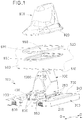
- FIG. 1 A perspective exploded view is shown in figure 1 of one example of the present antenna which has been generally illustrated by reference numeral 100.
- the antenna 100 of the example illustrated is intended to be mounted on a vehicle roof 500 so it will be referred hereafter to as roof antenna 100.
- the roof antenna 100 comprises a base member 200, an antenna device 300, an external cover or radome 900, an internal cover 1000 and a base member attaching device 400.
- the base member 200 and the internal cover 1000 may be separate parts attached to each other by any suitable means, as shown in the example shown in figure 2 .
- the base member 200 may be integrally formed with the internal cover 1000 as shown in the example shown in figure 3 .
- the base member 200 is provided with a detachable bottom portion 250 which serves the purpose of allowing the interior of the cover 1000 to be accessed.
- the antenna device 300 is connected to the base member 200 and attached thereto such that, in an assembled or operating condition, the antenna device 300 projects outwards the vehicle through an opening 550 that is formed in the vehicle roof 500.
- the interior of the cover 1000 is adapted for receiving a number of antenna parts of the antenna device 300.
- the antenna device 300 in the example shown includes an AM/FM radio device 925, a wireless communication device such as Long-Term Evolution devices 930, 935, a GPS with a Digital Audio Radio Service (DARS) radio device 940, a PCB circuit board 945, and other elements such as at least one processor for processing communication signals, etc. depending on the specific requirements of the vehicle antenna.
- the circuit board 945 is encapsulated inside the base member 200.
- the circuit board 945 is received inside the internal cover 1000 and is in turn attached to the base member 200.
- the base member 200 is encapsulated between the base member 200 and the internal cover 1000.
- the radome 900 is a shark fin shaped piece that is suitably configured to cooperate with the attaching device 400, which will be described further below, and the surroundings of the vehicle roof opening 550.
- the shark fin shaped radome 900 shown in the drawing is configured to sealingly enclose the antenna device 300 in an assembled condition, that is, when the roof antenna 100 has been installed and is ready for operation.
- the radome 900 is arranged over the antenna device 300 covering and protecting the above mentioned antenna device parts from damages, weather, etc.
- Electrical contact means 260 are provided for electrical contact of the base member 200 with the vehicle. Specifically, the electrical contact means 260 are provided for allowing the antenna device 300, i.e. the circuit board 945, to be grounded to the motor vehicle.
- the electrical contact means comprise a number of electrical contact pins 260 projecting outwards from the base member 200.
- Such contact pins 260 are attached on a top portion 240 of the base member 200 in the vicinity of the internal cover 1000 in a manner suitable to prevent undesired resonances.
- the electrical contact pins 260 are distributed around the outer perimeter of the internal cover 1000 and spaced apart from each other a suitable separation distance.
- Such separation distance is preferred to be less than half the wavelength of the highest operating frequency of the antenna device 300.
- the separation distance between electrical contact pins 260 is less than 50 mm.
- the electrical contact means 260 are continuous.
- the electrical contact means 260 may be a metal plate projecting outwards from the base member 200. The metal plate would be attached on a top portion 240 of the base member 200 surrounding the internal cover 1000 in a manner suitable to prevent undesired resonances.
- a combination of metal plates and contact pins is also possible as long as an electrical continuity exists between the base member 200 and the vehicle, such as the vehicle roof 500.
- a device 400 for attaching the base member 200 to an inside surface 510 of a vehicle roof 500 is provided in the present roof antenna 100.
- the attaching device 400 comprises a set of elastic tabs or clips 600, two foam elements 700 and a plurality of adhesive elements.
- the set of elastic tabs or clips includes eight stainless steel elastic tabs 600.
- the elastic tabs 600 are configured for allowing preassembly or pre-attachment of the base member 200, with the antenna device 300, in the vehicle roof opening 550.
- the preassembly or pre-attachment function of the base member 200 by the elastic tabs 600 allows time for definitive attachment of the base member 200 by the adhesive elements as it will be explained hereinbelow.
- the elastic tabs 600 are arranged surrounding the antenna device 300 such that they are ready for locking the base member 200 to the vehicle roof opening 550. This is carried out by a thrusting action exerted by the tabs 600 along directions D extending outwards the perimeter of the vehicle roof opening 550.
- the elastic tabs 600 are adapted to be received into tab housings 650 formed around the antenna device 300.
- Tab housings 650 are formed into a guided shape and a stop contact is provided therein to ensure that the elastic tabs 600 can be received properly into the corresponding tab housings 650 in any condition even if the elastic tabs 600 become deformed upon assembly of the roof antenna 100.
- the foam elements 700 are intended for absorbing vibrations when the roof antenna 100 is assembled.
- the foam elements 700 are arranged in the base member 200 contacting the inside surface 510 of the vehicle roof 500.
- a plurality of adhesive elements are provided for suitably attaching the base member 200 to the inside surface 510 of the vehicle roof 500.
- the adhesive elements are sealing joints and at least one of them is a self-adhesive sealing joint arranged surrounding the antenna device 300.
- a first adhesive element 800 is arranged between the base member 200 and the inside surface 510 of the vehicle roof 500.
- a second adhesive element 950 is arranged between the radome 900 and the outside surface 520 of the vehicle roof 500, and it is intended to be fitted in the vehicle roof opening 550 for properly sealing it.
- the second adhesive element 950 is adapted to act as a seat for radome 900.
- a third adhesive element 970 is arranged surrounding a perimetric recess 920 of the radome 900 as shown in figure 1 . In the example of figure 2 , the third adhesive element 970 is not provided.
- the first and second adhesive elements 800, 950 are received into shaped channels, not shown, formed in the base member 200 and the radome 900, respectively.
- the shaped channels might be formed in the inside and outside surfaces 510, 520 of the vehicle roof 500, respectively.
- the geometry of said channels is adapted to enhance sealing of the base member 200 and the radome 900.
- the internal cover 1000 is adapted to be mounted over the antenna device 300 within the radome 900.
- An attaching portion, not shown, is provided in the internal cover 1000 for attachment to the base member 200.
- the method for assembling the above roof antenna 100 is as follows.
- the antenna device 300 is connected to the base member 200.
- a protective sheet is removed from the first adhesive element 800 and then the base member 200 is placed under the vehicle roof opening 550 and the antenna device 300 is passed through the vehicle roof opening 550 outwards the vehicle.
- Elastic tabs 600 then begin to deform as they are urged along directions extending inwards the perimeter of the vehicle roof opening 550.
- the tabs 600 become received in the corresponding housings 650 in the antenna device 300 such that they return back to their original shape, locking the base member 200 with the antenna device 300 in position by interference with the vehicle roof opening 500.
- a protective sheet is then removed from the second and third adhesive elements 950, 970 and the radome 900 is placed covering the antenna device 300.
- the radome 900 is pressed by the operator against the vehicle roof outside surface 520, specifically against a corresponding roof print, until the radome 900 becomes fixed thereto.
- the surroundings of the vehicle roof opening 550 are stamped to provide a substantially flat surface to which the first and second adhesive elements 800, 950 are adhered. After stamping, the previous assembling method is performed.
Landscapes
- Engineering & Computer Science (AREA)
- Remote Sensing (AREA)
- Support Of Aerials (AREA)
- Details Of Aerials (AREA)
Description
- The present disclosure relates to antennas for motor vehicles and methods for assembling such antennas in a motor vehicle.
- Antennas intended to be mounted on motor vehicles are known in the art. Such antennas mainly comprise a base member, an antenna device mounted thereon, and an attaching device for attaching the base member to a part of a vehicle. An external cover is usually provided for covering the antenna device in order to protect the inner parts from damages.
- One example of such antennas for motor vehicles where the base member is adapted to be attached to a portion of a vehicle is disclosed in
US7304614 . The base member is attached to the roof of the vehicle by preassembling the base member on top of the roof and then securing the base member thereto through a fastening screw. - The assembly of the antenna on a motor vehicle from the outside has been shown to involve sealing problems. Tightness between the external cover and the antenna device has been shown not to be entirely adequate in all conditions.
-
US8368609 shows an omnidirectional antenna that can be mounted in a vehicle roof through the use of mounting clips or adhesives. In this case, the antenna is mounted from the inside of the motor vehicle such that it is suspended from the vehicle roof. - Suspended antenna attachments are complex. In addition, even though both inner and outer sealing means are applied, absolute tightness cannot be ensured in all conditions, especially with regard to the base member and the parts of the antenna device mounted thereon.
-
US2015123854 discloses an antenna module comprising an outer cover projecting out of a vehicle roof and an antenna box that accommodates a circuit board and that can be attached below the vehicle roof. The antenna box has an electrically conductive part that is electrically connected to the vehicle roof. -
EP0788668 refers to an antenna for motor vehicles comprising a socket with a peripheral detent groove intended for receiving a peripheral edge of an opening in a vehicle roof. The socket has an axially-aligned annular recess into which a detent ring, which can be locked on the socket, can be introduced from an end face of the socket. -
US6509878 provides an antenna mounting system comprising an internal mount and an external mount. The internal mount includes a main body with a positioning portion and an arrow-shaped resilient catch member for convenient installation a on vehicle panel. - In
WO2015003384 an antenna assembly is disclosed for installation to a vehicle body comprising a base, first and second antennas and a radome secured to the base. The base is coupled to a vehicle roof. Retaining components are provided for fixedly mounting the antenna to a vehicle roof. -
US2010231467 relates to a vehicle antenna with a base portion, a top portion attached thereto, and a printed circuit board held between said portions and carrying at least one transmission or receiver element. The top portion has at least one latching hook for latching into a mounting opening of a vehicle body part. - A need therefore exists for an improved antenna for motor vehicles which may provide high efficiency in sealing while being easy, simple and fast to assemble to a vehicle.
- An antenna for motor vehicles according to claim 1 is disclosed herein with which the problems related to prior art antennas are overcome and with which a number of advantages are obtained.
- The present antenna is intended to be mounted on a vehicle roof although it can be mounted on any other parts of a vehicle. The present antenna has a base member intended to be attached to a part of a motor vehicle, for example the roof as mentioned above. The base member is adapted for receiving an antenna device such that it is connected thereto. The antenna device may include therein antenna parts as required such as means for receiving and/or sending communication signals, a processor for processing communication signals, a main circuit board, and other elements such as GPS modules and so forth.
- An attaching device is provided for attaching the base member to an inside surface of a vehicle. As used herein, an inside surface of a vehicle refers to a part within the vehicle, such as an inner part of the vehicle roof. However, other different locations within a motor vehicle where the present antenna can be attached are also possible.
- Attachment of the base member to an inside surface of a vehicle is carried out such that, in an operating condition, that is, with the antenna assembled ready for operation, the antenna device projects outwards the vehicle from within through an opening that is formed in the vehicle for that purpose.
- Electrical contact means are provided for suitable electrical contact of the base member with the vehicle. Such electrical contact means are sized and arranged for allowing the antenna device to be suitably grounded to the motor vehicle. The contact means may be one or more metal elements projecting outwards from the base member, such as for example electrical contact pins spaced apart from each other, a continuous a metal plate, or a combination of metal plates and contact pins.
- The feature that the attaching device is adapted for attaching the base member to an inside surface of a vehicle has been proven to be very advantageous in terms of efficiency of sealing the antenna device. Attachment of the antenna to the motor vehicle is carried out only between the base member and the motor vehicle, with no additional parts required to be involved.
- In one example, the antenna may further comprise an external cover or radome arranged over the antenna device for covering the interior parts thereof and for protecting them from damages from outside the vehicle such as weather, dirt, impacts, etc. The radome may be a decorative cover which is preferably sized and shaped to match the overall vehicle appearance, lines and aerodynamics. For example the radome may be shark fin shaped. In any case, it is preferred that the radome is configured to cooperate with the attaching device and the surroundings of the vehicle opening so as to enclose the antenna device in an assembled condition. More preferably, the radome is configured to sealingly enclose the antenna device in the assembled condition in order to ensure good protection of parts thereof from damages from outside the vehicle.
- The attaching device comprises a set of tabs or clips made of an elastic material such as for example plastics, metal or any suitable material or combinations of materials. The elasticity of the tabs or clips is such that they are suitable for locking the base member to the vehicle, for example the roof, through their thrusting action along directions extending outwards the perimeter of the opening. Thus, the elastic tabs or clips allow the base member with the antenna device to be preassembled to the vehicle while allowing time for definitive attachment of the attaching device, specifically allowing time for definitive attachment of adhesive elements which will be described below. Other types of definitive attachments are not ruled out such as screwing or riveting.
- The elastic tabs are arranged at least substantially surrounding the antenna device.
- In some examples, the attaching device may additionally comprise at least one foam element for absorbing vibrations when the antenna is in an assembled condition. The foam element or elements may be arranged in the base member contacting the inside surface of the vehicle.
- The attaching device additionally comprises a first adhesive element and optionally a second adhesive element. At least one of such first and second adhesive elements may be for example a suitable adhesive sealing joint.
- The attaching device comprises a first adhesive element, adapted to be arranged between the base member and the inside of the vehicle in an assembled condition, that is, between the base member and a vehicle inside surface.
- In the example where the attaching device comprises a second adhesive element, it may be adapted to be arranged between the radome and the outside of the vehicle in an assembled condition, that is, between the radome and a vehicle outside surface.
- The radome thus serves the purpose of protecting the inside parts of the antenna device while sealing the assembly against the vehicle, such as for example the roof, through the above mentioned second adhesive element. If required, sealing material such as silicone can be applied, in addition to the second adhesive element, around the attachment between the radome and the vehicle.
- At least one of said first and second adhesive elements may be arranged at least substantially surrounding the antenna device. Other arrangements for the at least one of the first and second adhesive elements relative to the antenna device are not ruled out such as for example covering only one side of the antenna device perimeter.
- An internal cover may be also included. Such internal cover may be arranged over the antenna device within the radome. The internal cover may include an attaching portion for attachment of the internal cover to the base member.
- In one preferred example, the internal cover may be integrally formed with the base member. However, the base member and the internal cover may be separate parts attached to each other by any suitable means.
- Assembling the above described antenna is very quick, simple and efficient. An antenna device is attached to a base member and then the antenna device is passed outwards from within the motor vehicle through an opening in the vehicle. The base member is then attached to an inside surface of the vehicle through the above mentioned attachment device, by first preassembling the base member by the elastic tabs. Then, the base member is definitively attached to the inside surface of the vehicle by adhesive elements such that, in operation, the antenna device projects outwards of the vehicle from the inside. The radome is then attached to an outside surface of the vehicle, such as for example the roof, so that the antenna device is sealingly enclosed therein. Permanent sealing means can be then applied to the inside and outside surfaces of the vehicle.
- To increase sealing efficiency, the surroundings of the vehicle opening are stamped to provide a substantially flat surface where the first and second adhesive elements are adhered. This increases the contact surface between the attachment device, the base member and the external cover or radome, if present. This is particularly advantageous when adhesive elements are provided to definitively attach the antenna device to the vehicle.
- One advantage of the assembling method of the above described antenna is that, once assembled, the radome is not attached to the base member but to the vehicle. This results in highly improved sealing and tightness.
- Additional objects, advantages and features of examples of the present antenna for motor vehicles and assembling method will become apparent to those skilled in the art upon examination of the description, or may be learned by practice thereof.
- Particular examples of the present antenna for motor vehicles will be described in the following with reference to the appended drawings, in which:
-
Figure 1 diagrammatically shows a perspective exploded view of one example of an antenna for motor vehicles; -
Figure 2 is a sectional view of a first example where the radome and the base member are separate parts; and -
Figure 3 is a sectional view of a second example where the radome and the base member are integrally formed with each other. - A perspective exploded view is shown in
figure 1 of one example of the present antenna which has been generally illustrated byreference numeral 100. Theantenna 100 of the example illustrated is intended to be mounted on avehicle roof 500 so it will be referred hereafter to asroof antenna 100. Theroof antenna 100 comprises abase member 200, anantenna device 300, an external cover orradome 900, aninternal cover 1000 and a basemember attaching device 400. - The
base member 200 and theinternal cover 1000 may be separate parts attached to each other by any suitable means, as shown in the example shown infigure 2 . However, thebase member 200 may be integrally formed with theinternal cover 1000 as shown in the example shown infigure 3 . - In both cases, the
base member 200 is provided with adetachable bottom portion 250 which serves the purpose of allowing the interior of thecover 1000 to be accessed. - The
antenna device 300 is connected to thebase member 200 and attached thereto such that, in an assembled or operating condition, theantenna device 300 projects outwards the vehicle through anopening 550 that is formed in thevehicle roof 500. - In any of the examples shown in the figures, the interior of the
cover 1000 is adapted for receiving a number of antenna parts of theantenna device 300. Some of such antenna parts have been diagrammatically illustrated infigures 2 and 3 . For example, theantenna device 300 in the example shown includes an AM/FM radio device 925, a wireless communication device such as Long-Term Evolution devices radio device 940, aPCB circuit board 945, and other elements such as at least one processor for processing communication signals, etc. depending on the specific requirements of the vehicle antenna. In the example shown infigure 2 where thebase member 200 and theinternal cover 1000 are separate parts, thecircuit board 945 is encapsulated inside thebase member 200. Instead, in the example shown infigure 3 where thebase member 200 is integrally formed with theinternal cover 1000, thecircuit board 945 is received inside theinternal cover 1000 and is in turn attached to thebase member 200. Thus, in this case, thebase member 200 is encapsulated between thebase member 200 and theinternal cover 1000. - The
radome 900 is a shark fin shaped piece that is suitably configured to cooperate with the attachingdevice 400, which will be described further below, and the surroundings of thevehicle roof opening 550. Specifically, the shark fin shapedradome 900 shown in the drawing is configured to sealingly enclose theantenna device 300 in an assembled condition, that is, when theroof antenna 100 has been installed and is ready for operation. In said assembled condition, theradome 900 is arranged over theantenna device 300 covering and protecting the above mentioned antenna device parts from damages, weather, etc. - Electrical contact means 260 are provided for electrical contact of the
base member 200 with the vehicle. Specifically, the electrical contact means 260 are provided for allowing theantenna device 300, i.e. thecircuit board 945, to be grounded to the motor vehicle. - In the specific example shown in
figure 1 of the drawings, the electrical contact means comprise a number of electrical contact pins 260 projecting outwards from thebase member 200. Such contact pins 260 are attached on atop portion 240 of thebase member 200 in the vicinity of theinternal cover 1000 in a manner suitable to prevent undesired resonances. The electrical contact pins 260 are distributed around the outer perimeter of theinternal cover 1000 and spaced apart from each other a suitable separation distance. Such separation distance is preferred to be less than half the wavelength of the highest operating frequency of theantenna device 300. For example, in the case of a LTE2600 working at a frequency of 3GHz, the separation distance between electrical contact pins 260 is less than 50 mm. - Alternatively it is also envisaged that the electrical contact means 260 are continuous. In this case, for example, the electrical contact means 260 may be a metal plate projecting outwards from the
base member 200. The metal plate would be attached on atop portion 240 of thebase member 200 surrounding theinternal cover 1000 in a manner suitable to prevent undesired resonances. A combination of metal plates and contact pins is also possible as long as an electrical continuity exists between thebase member 200 and the vehicle, such as thevehicle roof 500. - A
device 400 for attaching thebase member 200 to aninside surface 510 of avehicle roof 500 is provided in thepresent roof antenna 100. In the specific example shown, the attachingdevice 400 comprises a set of elastic tabs or clips 600, twofoam elements 700 and a plurality of adhesive elements. - The set of elastic tabs or clips includes eight stainless steel
elastic tabs 600. Theelastic tabs 600 are configured for allowing preassembly or pre-attachment of thebase member 200, with theantenna device 300, in thevehicle roof opening 550. The preassembly or pre-attachment function of thebase member 200 by theelastic tabs 600 allows time for definitive attachment of thebase member 200 by the adhesive elements as it will be explained hereinbelow. - For this purpose, the
elastic tabs 600 are arranged surrounding theantenna device 300 such that they are ready for locking thebase member 200 to thevehicle roof opening 550. This is carried out by a thrusting action exerted by thetabs 600 along directions D extending outwards the perimeter of thevehicle roof opening 550. - The
elastic tabs 600 are adapted to be received intotab housings 650 formed around theantenna device 300.Tab housings 650 are formed into a guided shape and a stop contact is provided therein to ensure that theelastic tabs 600 can be received properly into the correspondingtab housings 650 in any condition even if theelastic tabs 600 become deformed upon assembly of theroof antenna 100. - The
foam elements 700 are intended for absorbing vibrations when theroof antenna 100 is assembled. Thefoam elements 700 are arranged in thebase member 200 contacting theinside surface 510 of thevehicle roof 500. - In the example herein described, a plurality of adhesive elements are provided for suitably attaching the
base member 200 to theinside surface 510 of thevehicle roof 500. In the example shown infigure 1 of the drawing, the adhesive elements are sealing joints and at least one of them is a self-adhesive sealing joint arranged surrounding theantenna device 300. - A first
adhesive element 800 is arranged between thebase member 200 and theinside surface 510 of thevehicle roof 500. A secondadhesive element 950 is arranged between theradome 900 and theoutside surface 520 of thevehicle roof 500, and it is intended to be fitted in the vehicle roof opening 550 for properly sealing it. The secondadhesive element 950 is adapted to act as a seat forradome 900. A thirdadhesive element 970 is arranged surrounding aperimetric recess 920 of theradome 900 as shown infigure 1 . In the example offigure 2 , the thirdadhesive element 970 is not provided. - The first and second
adhesive elements base member 200 and theradome 900, respectively. Alternatively or additionally, the shaped channels might be formed in the inside and outsidesurfaces vehicle roof 500, respectively. In any case, the geometry of said channels is adapted to enhance sealing of thebase member 200 and theradome 900. - The
internal cover 1000 is adapted to be mounted over theantenna device 300 within theradome 900. An attaching portion, not shown, is provided in theinternal cover 1000 for attachment to thebase member 200. - The method for assembling the
above roof antenna 100 is as follows. - The
antenna device 300 is connected to thebase member 200. A protective sheet is removed from the firstadhesive element 800 and then thebase member 200 is placed under thevehicle roof opening 550 and theantenna device 300 is passed through the vehicle roof opening 550 outwards the vehicle.Elastic tabs 600 then begin to deform as they are urged along directions extending inwards the perimeter of thevehicle roof opening 550. - While the
antenna device 300 is being still passed through the vehicle roof opening 550 outwards the vehicle,elastic tabs 600 continue to deform until they become attached to thevehicle roof 500, which can be confirmed by a click sound. Thebase member 200 is still pressed by the operator against the vehicle roof insidesurface 510 in order to enhance effectiveness of the firstadhesive element 800. - Thereafter, the
tabs 600 become received in the correspondinghousings 650 in theantenna device 300 such that they return back to their original shape, locking thebase member 200 with theantenna device 300 in position by interference with thevehicle roof opening 500. - Finally, a protective sheet is then removed from the second and third
adhesive elements radome 900 is placed covering theantenna device 300. - The
radome 900 is pressed by the operator against the vehicle roof outsidesurface 520, specifically against a corresponding roof print, until theradome 900 becomes fixed thereto. - Preferably, the surroundings of the vehicle roof opening 550 are stamped to provide a substantially flat surface to which the first and second
adhesive elements
Claims (15)
- An antenna (100) for vehicles comprising a base member (200), an antenna device (300) connected to the base member (200) and an attaching device (400) adapted for attaching the base member (200) to an inside surface (510) of a vehicle with the antenna device (300) projecting outwards of the vehicle from within through an opening (550) formed in the vehicle in an assembled condition,wherein the attaching device (400) comprises:a set of elastic tabs (600) surrounding the antenna device (300), wherein the set of elastic tabs (600) is configured to lock the base member (200) to the vehicle through the thrusting action of the elastic tabs (600) against directions (D) extending outwards the perimeter of the vehicle opening (550) to pre-assembly the base member (200) in the opening (550) when the antenna device (300) is passed outwards from inside the vehicle through the opening (550), anda first adhesive element (800) adapted to be arranged between the base member (200) and the inside of the vehicle in the assembled condition to attach the base member to the inside of the vehicle; andwherein the antenna device (300) comprises a plurality of tab housings (650) to receive the corresponding elastic tabs (600).
- The antenna (100) according to claim 1, further comprising an electrical contact means (260) for electrical contact of the base member (200) with the vehicle.
- The antenna (100) according to claim 1 or 2, further comprising a radome (900) arranged over the antenna device (300), the radome (900) configured to cooperate with the attaching device (400) and the surroundings of the vehicle opening (550) so as to enclose the antenna device (300) in an assembled condition.
- The antenna (100) according to claim 3, where the radome (900) is configured to sealingly enclose the antenna device (300) in an assembled condition.
- The antenna (100) according to any of the preceding claims, where the attaching device (400) comprises at least one foam element (700) arranged at the base member (200) to contact the inside surface (510) of the vehicle for absorbing vibrations in an assembled condition.
- The antenna (100) according to any of the preceding claims, wherein the first adhesive element (800) is arranged substantially surrounding the antenna device (300).
- The antenna (100) according to any of the preceding claims, wherein the first adhesive element (800) is an adhesive sealing joint.
- The antenna (100) according to any of the preceding claims, further comprising a radome (900) arranged over the antenna device (300), the radome (900) configured to cooperate with the attaching device (400) and the surroundings of the vehicle opening (550) so as to enclose the antenna device (300) in an assembled condition; and
where the attaching device (400) comprises a second adhesive element (950) adapted to be arranged between the radome (900) and the outside of the vehicle in an assembled condition. - The antenna (100) according to claim 8, where the second adhesive element (950) is arranged at least substantially surrounding the antenna device (300).
- The antenna (100) according to any of claims 8-9, where the second adhesive element (950) is an adhesive sealing joint.
- The antenna (100) according to any of claims 2-10, where it further includes a radome (900) arranged over the antenna device (300), the radome (900) configured to cooperate with the attaching device (400) and the surroundings of the vehicle opening (550) so as to enclose the antenna device (300) in an assembled condition; and
an internal cover (1000) arranged over the antenna device (300) within the radome (900). - The antenna (100) according to claim 11, where the internal cover (1000) includes an attaching portion for attachment of the internal cover (1000) to the base member (200).
- Method for assembling an antenna (100) according to any of the preceding claims, the method comprising:attaching the antenna device (300) to the base member (200),inserting the antenna device (300) through the opening (550) formed in a vehicle from inside the vehicle; andattaching by an attachment device (400) the base member (200) to an inside surface (510) of the vehicle such that the antenna device (300) projects outwards of the vehicle from within through the opening (550), whereinattaching the base member (200) to an inside of the surface (510) comprises:locking the base member (200) to the vehicle through the thrusting action of the elastic tabs (600) against directions (D) extending outwards the perimeter of the vehicle opening (550) to preassembly the base member (200) in the opening (500) when the antenna device (300) is passed outwards from inside the vehicle through the opening (550);receiving the elastic tabs by the corresponding tab housings (650); andadhering the first adhesive element (800) to the inside surface (510) of the vehicle to attach the base member (200) to the inside of the vehicle.
- Method as claimed in claim 13, further comprising arranging a radome (900) over the antenna device (300) and attaching by the attachment device (400) the radome (900) to an outside surface (520) of the vehicle so as to sealingly enclose the antenna device (300).
- Method as claimed in claim 13 or 14, further comprising stamping the surroundings of the vehicle opening (550) to obtain a substantially flat surface.
Priority Applications (3)
| Application Number | Priority Date | Filing Date | Title |
|---|---|---|---|
| ES15195995T ES2897763T3 (en) | 2015-11-24 | 2015-11-24 | Vehicle antennas and mounting procedures |
| EP15195995.4A EP3174157B1 (en) | 2015-11-24 | 2015-11-24 | Antenna for motor vehicles and assembling method |
| US15/359,713 US10541469B2 (en) | 2015-11-24 | 2016-11-23 | Antenna for motor vehicles and assembling method |
Applications Claiming Priority (1)
| Application Number | Priority Date | Filing Date | Title |
|---|---|---|---|
| EP15195995.4A EP3174157B1 (en) | 2015-11-24 | 2015-11-24 | Antenna for motor vehicles and assembling method |
Publications (2)
| Publication Number | Publication Date |
|---|---|
| EP3174157A1 EP3174157A1 (en) | 2017-05-31 |
| EP3174157B1 true EP3174157B1 (en) | 2021-09-08 |
Family
ID=54703852
Family Applications (1)
| Application Number | Title | Priority Date | Filing Date |
|---|---|---|---|
| EP15195995.4A Active EP3174157B1 (en) | 2015-11-24 | 2015-11-24 | Antenna for motor vehicles and assembling method |
Country Status (3)
| Country | Link |
|---|---|
| US (1) | US10541469B2 (en) |
| EP (1) | EP3174157B1 (en) |
| ES (1) | ES2897763T3 (en) |
Families Citing this family (6)
| Publication number | Priority date | Publication date | Assignee | Title |
|---|---|---|---|---|
| JP6748610B2 (en) * | 2017-07-03 | 2020-09-02 | 原田工業株式会社 | Antenna device |
| CN111492534B (en) * | 2017-12-20 | 2023-02-17 | 株式会社友华 | Vehicle-mounted antenna device |
| AU2019258584B2 (en) * | 2018-04-23 | 2023-11-16 | NetComm Wireless Pty Ltd | Lightweight radome for housing an antenna |
| US11201414B2 (en) * | 2018-12-18 | 2021-12-14 | Veoneer Us, Inc. | Waveguide sensor assemblies and related methods |
| FR3093256B1 (en) * | 2019-02-27 | 2021-01-29 | Psa Automobiles Sa | DISSYMMETRIC CALORIE TRANSFER WAVE EMISSION / RECEPTION DEVICE, FOR A BODY WALL OF A VEHICLE |
| DE102019215533B3 (en) * | 2019-10-10 | 2021-01-14 | Continental Automotive Gmbh | Vehicle comprising an antenna device as well as antenna device and fastening device |
Family Cites Families (12)
| Publication number | Priority date | Publication date | Assignee | Title |
|---|---|---|---|---|
| DE9416874U1 (en) * | 1994-10-24 | 1995-02-02 | Sihn Jr Kg Wilhelm | Detachable antenna |
| DE4439388C1 (en) * | 1994-11-04 | 1996-02-15 | Daimler Benz Ag | Radio aerial mounted on bodywork of motor vehicle |
| US6509878B1 (en) * | 2001-04-02 | 2003-01-21 | Radiall/Larsen Antenna Technologies, Inc. | Antenna mounting system |
| DE102005033177A1 (en) | 2005-07-13 | 2007-01-25 | Hirschmann Car Communication Gmbh | Roof antenna for a vehicle with a base plate made of sheet metal |
| US8368609B2 (en) | 2008-10-21 | 2013-02-05 | Laird Technologies, Inc. | Omnidirectional multiple input multiple output (MIMO) antennas with polarization diversity |
| DE102009012641A1 (en) * | 2009-03-10 | 2010-09-23 | Wilhelm Sihn Jr. Gmbh & Co. Kg | vehicle antenna |
| US8537062B1 (en) * | 2010-09-30 | 2013-09-17 | Laird Technologies, Inc. | Low-profile antenna assemblies |
| DE102012208303B4 (en) * | 2012-05-16 | 2014-05-15 | Continental Automotive Gmbh | Antenna module with transmitting and receiving antenna element |
| KR101814301B1 (en) * | 2013-07-12 | 2018-01-02 | 라이르드 테크놀로지스 (상하이) 코., 엘티디. | Multiband vehicular antenna assemblies |
| JP6437227B2 (en) * | 2014-07-18 | 2018-12-12 | 株式会社ヨコオ | In-vehicle antenna device |
| JP5989722B2 (en) * | 2014-08-04 | 2016-09-07 | 原田工業株式会社 | Antenna device |
| US20170054204A1 (en) * | 2015-08-21 | 2017-02-23 | Laird Technologies, Inc. | V2x antenna systems |
-
2015
- 2015-11-24 ES ES15195995T patent/ES2897763T3/en active Active
- 2015-11-24 EP EP15195995.4A patent/EP3174157B1/en active Active
-
2016
- 2016-11-23 US US15/359,713 patent/US10541469B2/en active Active
Also Published As
| Publication number | Publication date |
|---|---|
| US20170149124A1 (en) | 2017-05-25 |
| US10541469B2 (en) | 2020-01-21 |
| EP3174157A1 (en) | 2017-05-31 |
| ES2897763T3 (en) | 2022-03-02 |
Similar Documents
| Publication | Publication Date | Title |
|---|---|---|
| EP3174157B1 (en) | Antenna for motor vehicles and assembling method | |
| EP2092599B1 (en) | Vehicle-mount antenna assemblies having snap-on outer cosmetic covers with compliant latching mechanisms for achieving zero-gap | |
| US7755551B2 (en) | Modular antenna assembly for automotive vehicles | |
| US10008767B2 (en) | Vehicle-mount antenna assemblies having outer covers with back tension latching mechanisms for achieving zero-gap | |
| US7768465B2 (en) | Vehicle-mount stacked patch antenna assemblies with resiliently compressible bumpers for mechanical compression to aid in electrical grounding of shield and chassis | |
| US20080100521A1 (en) | Antenna assemblies with composite bases | |
| JP5882127B2 (en) | Automotive antenna | |
| US7492319B2 (en) | Antenna assemblies including standard electrical connections and captured retainers and fasteners | |
| US7333065B2 (en) | Modular antenna assembly for automotive vehicles | |
| US7580002B2 (en) | Antenna unit with a top cover painted in one of various colors | |
| US20060012533A1 (en) | Antenna device | |
| US8059044B2 (en) | Antenna mounting apparatus and methods including claw fasteners and/or bayonet locking structures | |
| US7387518B2 (en) | Grounding attachment assembly | |
| JP4774565B2 (en) | Antenna device | |
| JP2010259034A (en) | Antenna device | |
| JP6855546B2 (en) | In-vehicle device, mounting part of in-vehicle device | |
| JP2014082565A (en) | Vehicular antenna cover | |
| EP3273535B1 (en) | Antenna mounting component and antenna device | |
| JP3754680B2 (en) | Vehicle antenna device | |
| US7466280B2 (en) | Protector-equipped antenna unit using an already-existing antenna unit as an antenna body | |
| CN209822855U (en) | Fixing device for vehicle-mounted antenna assembly and antenna assembly | |
| CN113270833A (en) | Wire harness via hole protection device | |
| KR200284252Y1 (en) | Multiaccess antenna | |
| KR20210129926A (en) | Vehicle and antenna for vehicle | |
| JP6931962B2 (en) | Automotive antenna device |
Legal Events
| Date | Code | Title | Description |
|---|---|---|---|
| PUAI | Public reference made under article 153(3) epc to a published international application that has entered the european phase |
Free format text: ORIGINAL CODE: 0009012 |
|
| STAA | Information on the status of an ep patent application or granted ep patent |
Free format text: STATUS: THE APPLICATION HAS BEEN PUBLISHED |
|
| AK | Designated contracting states |
Kind code of ref document: A1 Designated state(s): AL AT BE BG CH CY CZ DE DK EE ES FI FR GB GR HR HU IE IS IT LI LT LU LV MC MK MT NL NO PL PT RO RS SE SI SK SM TR |
|
| AX | Request for extension of the european patent |
Extension state: BA ME |
|
| STAA | Information on the status of an ep patent application or granted ep patent |
Free format text: STATUS: REQUEST FOR EXAMINATION WAS MADE |
|
| 17P | Request for examination filed |
Effective date: 20171130 |
|
| RBV | Designated contracting states (corrected) |
Designated state(s): AL AT BE BG CH CY CZ DE DK EE ES FI FR GB GR HR HU IE IS IT LI LT LU LV MC MK MT NL NO PL PT RO RS SE SI SK SM TR |
|
| STAA | Information on the status of an ep patent application or granted ep patent |
Free format text: STATUS: EXAMINATION IS IN PROGRESS |
|
| 17Q | First examination report despatched |
Effective date: 20200212 |
|
| STAA | Information on the status of an ep patent application or granted ep patent |
Free format text: STATUS: EXAMINATION IS IN PROGRESS |
|
| GRAP | Despatch of communication of intention to grant a patent |
Free format text: ORIGINAL CODE: EPIDOSNIGR1 |
|
| STAA | Information on the status of an ep patent application or granted ep patent |
Free format text: STATUS: GRANT OF PATENT IS INTENDED |
|
| RIC1 | Information provided on ipc code assigned before grant |
Ipc: H01Q 21/30 20060101ALN20210607BHEP Ipc: H01Q 1/42 20060101ALI20210607BHEP Ipc: H01Q 1/32 20060101ALI20210607BHEP Ipc: H01Q 1/12 20060101AFI20210607BHEP |
|
| INTG | Intention to grant announced |
Effective date: 20210702 |
|
| GRAS | Grant fee paid |
Free format text: ORIGINAL CODE: EPIDOSNIGR3 |
|
| GRAA | (expected) grant |
Free format text: ORIGINAL CODE: 0009210 |
|
| STAA | Information on the status of an ep patent application or granted ep patent |
Free format text: STATUS: THE PATENT HAS BEEN GRANTED |
|
| AK | Designated contracting states |
Kind code of ref document: B1 Designated state(s): AL AT BE BG CH CY CZ DE DK EE ES FI FR GB GR HR HU IE IS IT LI LT LU LV MC MK MT NL NO PL PT RO RS SE SI SK SM TR |
|
| REG | Reference to a national code |
Ref country code: GB Ref legal event code: FG4D |
|
| REG | Reference to a national code |
Ref country code: CH Ref legal event code: EP Ref country code: AT Ref legal event code: REF Ref document number: 1429392 Country of ref document: AT Kind code of ref document: T Effective date: 20210915 |
|
| REG | Reference to a national code |
Ref country code: DE Ref legal event code: R096 Ref document number: 602015073055 Country of ref document: DE |
|
| REG | Reference to a national code |
Ref country code: IE Ref legal event code: FG4D |
|
| REG | Reference to a national code |
Ref country code: LT Ref legal event code: MG9D |
|
| REG | Reference to a national code |
Ref country code: NL Ref legal event code: MP Effective date: 20210908 |
|
| PG25 | Lapsed in a contracting state [announced via postgrant information from national office to epo] |
Ref country code: HR Free format text: LAPSE BECAUSE OF FAILURE TO SUBMIT A TRANSLATION OF THE DESCRIPTION OR TO PAY THE FEE WITHIN THE PRESCRIBED TIME-LIMIT Effective date: 20210908 Ref country code: RS Free format text: LAPSE BECAUSE OF FAILURE TO SUBMIT A TRANSLATION OF THE DESCRIPTION OR TO PAY THE FEE WITHIN THE PRESCRIBED TIME-LIMIT Effective date: 20210908 Ref country code: SE Free format text: LAPSE BECAUSE OF FAILURE TO SUBMIT A TRANSLATION OF THE DESCRIPTION OR TO PAY THE FEE WITHIN THE PRESCRIBED TIME-LIMIT Effective date: 20210908 Ref country code: LT Free format text: LAPSE BECAUSE OF FAILURE TO SUBMIT A TRANSLATION OF THE DESCRIPTION OR TO PAY THE FEE WITHIN THE PRESCRIBED TIME-LIMIT Effective date: 20210908 Ref country code: BG Free format text: LAPSE BECAUSE OF FAILURE TO SUBMIT A TRANSLATION OF THE DESCRIPTION OR TO PAY THE FEE WITHIN THE PRESCRIBED TIME-LIMIT Effective date: 20211208 Ref country code: FI Free format text: LAPSE BECAUSE OF FAILURE TO SUBMIT A TRANSLATION OF THE DESCRIPTION OR TO PAY THE FEE WITHIN THE PRESCRIBED TIME-LIMIT Effective date: 20210908 Ref country code: NO Free format text: LAPSE BECAUSE OF FAILURE TO SUBMIT A TRANSLATION OF THE DESCRIPTION OR TO PAY THE FEE WITHIN THE PRESCRIBED TIME-LIMIT Effective date: 20211208 |
|
| REG | Reference to a national code |
Ref country code: AT Ref legal event code: MK05 Ref document number: 1429392 Country of ref document: AT Kind code of ref document: T Effective date: 20210908 |
|
| PG25 | Lapsed in a contracting state [announced via postgrant information from national office to epo] |
Ref country code: LV Free format text: LAPSE BECAUSE OF FAILURE TO SUBMIT A TRANSLATION OF THE DESCRIPTION OR TO PAY THE FEE WITHIN THE PRESCRIBED TIME-LIMIT Effective date: 20210908 Ref country code: GR Free format text: LAPSE BECAUSE OF FAILURE TO SUBMIT A TRANSLATION OF THE DESCRIPTION OR TO PAY THE FEE WITHIN THE PRESCRIBED TIME-LIMIT Effective date: 20211209 |
|
| REG | Reference to a national code |
Ref country code: ES Ref legal event code: FG2A Ref document number: 2897763 Country of ref document: ES Kind code of ref document: T3 Effective date: 20220302 |
|
| PG25 | Lapsed in a contracting state [announced via postgrant information from national office to epo] |
Ref country code: AT Free format text: LAPSE BECAUSE OF FAILURE TO SUBMIT A TRANSLATION OF THE DESCRIPTION OR TO PAY THE FEE WITHIN THE PRESCRIBED TIME-LIMIT Effective date: 20210908 |
|
| PG25 | Lapsed in a contracting state [announced via postgrant information from national office to epo] |
Ref country code: IS Free format text: LAPSE BECAUSE OF FAILURE TO SUBMIT A TRANSLATION OF THE DESCRIPTION OR TO PAY THE FEE WITHIN THE PRESCRIBED TIME-LIMIT Effective date: 20220108 Ref country code: SM Free format text: LAPSE BECAUSE OF FAILURE TO SUBMIT A TRANSLATION OF THE DESCRIPTION OR TO PAY THE FEE WITHIN THE PRESCRIBED TIME-LIMIT Effective date: 20210908 Ref country code: SK Free format text: LAPSE BECAUSE OF FAILURE TO SUBMIT A TRANSLATION OF THE DESCRIPTION OR TO PAY THE FEE WITHIN THE PRESCRIBED TIME-LIMIT Effective date: 20210908 Ref country code: RO Free format text: LAPSE BECAUSE OF FAILURE TO SUBMIT A TRANSLATION OF THE DESCRIPTION OR TO PAY THE FEE WITHIN THE PRESCRIBED TIME-LIMIT Effective date: 20210908 Ref country code: PT Free format text: LAPSE BECAUSE OF FAILURE TO SUBMIT A TRANSLATION OF THE DESCRIPTION OR TO PAY THE FEE WITHIN THE PRESCRIBED TIME-LIMIT Effective date: 20220110 Ref country code: PL Free format text: LAPSE BECAUSE OF FAILURE TO SUBMIT A TRANSLATION OF THE DESCRIPTION OR TO PAY THE FEE WITHIN THE PRESCRIBED TIME-LIMIT Effective date: 20210908 Ref country code: NL Free format text: LAPSE BECAUSE OF FAILURE TO SUBMIT A TRANSLATION OF THE DESCRIPTION OR TO PAY THE FEE WITHIN THE PRESCRIBED TIME-LIMIT Effective date: 20210908 Ref country code: EE Free format text: LAPSE BECAUSE OF FAILURE TO SUBMIT A TRANSLATION OF THE DESCRIPTION OR TO PAY THE FEE WITHIN THE PRESCRIBED TIME-LIMIT Effective date: 20210908 Ref country code: CZ Free format text: LAPSE BECAUSE OF FAILURE TO SUBMIT A TRANSLATION OF THE DESCRIPTION OR TO PAY THE FEE WITHIN THE PRESCRIBED TIME-LIMIT Effective date: 20210908 Ref country code: AL Free format text: LAPSE BECAUSE OF FAILURE TO SUBMIT A TRANSLATION OF THE DESCRIPTION OR TO PAY THE FEE WITHIN THE PRESCRIBED TIME-LIMIT Effective date: 20210908 |
|
| REG | Reference to a national code |
Ref country code: DE Ref legal event code: R097 Ref document number: 602015073055 Country of ref document: DE |
|
| PG25 | Lapsed in a contracting state [announced via postgrant information from national office to epo] |
Ref country code: MC Free format text: LAPSE BECAUSE OF FAILURE TO SUBMIT A TRANSLATION OF THE DESCRIPTION OR TO PAY THE FEE WITHIN THE PRESCRIBED TIME-LIMIT Effective date: 20210908 |
|
| REG | Reference to a national code |
Ref country code: CH Ref legal event code: PL |
|
| PLBE | No opposition filed within time limit |
Free format text: ORIGINAL CODE: 0009261 |
|
| STAA | Information on the status of an ep patent application or granted ep patent |
Free format text: STATUS: NO OPPOSITION FILED WITHIN TIME LIMIT |
|
| PG25 | Lapsed in a contracting state [announced via postgrant information from national office to epo] |
Ref country code: LU Free format text: LAPSE BECAUSE OF NON-PAYMENT OF DUE FEES Effective date: 20211124 Ref country code: DK Free format text: LAPSE BECAUSE OF FAILURE TO SUBMIT A TRANSLATION OF THE DESCRIPTION OR TO PAY THE FEE WITHIN THE PRESCRIBED TIME-LIMIT Effective date: 20210908 Ref country code: BE Free format text: LAPSE BECAUSE OF NON-PAYMENT OF DUE FEES Effective date: 20211130 |
|
| REG | Reference to a national code |
Ref country code: BE Ref legal event code: MM Effective date: 20211130 |
|
| 26N | No opposition filed |
Effective date: 20220609 |
|
| GBPC | Gb: european patent ceased through non-payment of renewal fee |
Effective date: 20211208 |
|
| PG25 | Lapsed in a contracting state [announced via postgrant information from national office to epo] |
Ref country code: SI Free format text: LAPSE BECAUSE OF FAILURE TO SUBMIT A TRANSLATION OF THE DESCRIPTION OR TO PAY THE FEE WITHIN THE PRESCRIBED TIME-LIMIT Effective date: 20210908 |
|
| PG25 | Lapsed in a contracting state [announced via postgrant information from national office to epo] |
Ref country code: IE Free format text: LAPSE BECAUSE OF NON-PAYMENT OF DUE FEES Effective date: 20211124 Ref country code: GB Free format text: LAPSE BECAUSE OF NON-PAYMENT OF DUE FEES Effective date: 20211208 |
|
| PG25 | Lapsed in a contracting state [announced via postgrant information from national office to epo] |
Ref country code: FR Free format text: LAPSE BECAUSE OF NON-PAYMENT OF DUE FEES Effective date: 20211130 |
|
| PG25 | Lapsed in a contracting state [announced via postgrant information from national office to epo] |
Ref country code: IT Free format text: LAPSE BECAUSE OF FAILURE TO SUBMIT A TRANSLATION OF THE DESCRIPTION OR TO PAY THE FEE WITHIN THE PRESCRIBED TIME-LIMIT Effective date: 20210908 |
|
| PG25 | Lapsed in a contracting state [announced via postgrant information from national office to epo] |
Ref country code: HU Free format text: LAPSE BECAUSE OF FAILURE TO SUBMIT A TRANSLATION OF THE DESCRIPTION OR TO PAY THE FEE WITHIN THE PRESCRIBED TIME-LIMIT; INVALID AB INITIO Effective date: 20151124 |
|
| PG25 | Lapsed in a contracting state [announced via postgrant information from national office to epo] |
Ref country code: CY Free format text: LAPSE BECAUSE OF FAILURE TO SUBMIT A TRANSLATION OF THE DESCRIPTION OR TO PAY THE FEE WITHIN THE PRESCRIBED TIME-LIMIT Effective date: 20210908 |
|
| PG25 | Lapsed in a contracting state [announced via postgrant information from national office to epo] |
Ref country code: LI Free format text: LAPSE BECAUSE OF NON-PAYMENT OF DUE FEES Effective date: 20220630 Ref country code: CH Free format text: LAPSE BECAUSE OF NON-PAYMENT OF DUE FEES Effective date: 20220630 |
|
| PGFP | Annual fee paid to national office [announced via postgrant information from national office to epo] |
Ref country code: ES Payment date: 20231201 Year of fee payment: 9 |
|
| PGFP | Annual fee paid to national office [announced via postgrant information from national office to epo] |
Ref country code: DE Payment date: 20231129 Year of fee payment: 9 |
|
| PG25 | Lapsed in a contracting state [announced via postgrant information from national office to epo] |
Ref country code: MK Free format text: LAPSE BECAUSE OF FAILURE TO SUBMIT A TRANSLATION OF THE DESCRIPTION OR TO PAY THE FEE WITHIN THE PRESCRIBED TIME-LIMIT Effective date: 20210908 |