EP3171676B1 - Plasma generating device, plasma generating system and method of generating plasma - Google Patents
Plasma generating device, plasma generating system and method of generating plasma Download PDFInfo
- Publication number
- EP3171676B1 EP3171676B1 EP15195015.1A EP15195015A EP3171676B1 EP 3171676 B1 EP3171676 B1 EP 3171676B1 EP 15195015 A EP15195015 A EP 15195015A EP 3171676 B1 EP3171676 B1 EP 3171676B1
- Authority
- EP
- European Patent Office
- Prior art keywords
- plasma generating
- generating device
- electrode
- plasma
- voltage
- Prior art date
- Legal status (The legal status is an assumption and is not a legal conclusion. Google has not performed a legal analysis and makes no representation as to the accuracy of the status listed.)
- Active
Links
- 238000000034 method Methods 0.000 title claims description 7
- 125000006850 spacer group Chemical group 0.000 claims description 31
- 239000004744 fabric Substances 0.000 claims description 14
- 229920001971 elastomer Polymers 0.000 claims description 7
- 239000000806 elastomer Substances 0.000 claims description 7
- 239000004020 conductor Substances 0.000 claims description 5
- 239000011888 foil Substances 0.000 claims description 5
- 239000002759 woven fabric Substances 0.000 claims description 5
- 238000009413 insulation Methods 0.000 claims description 4
- 210000002381 plasma Anatomy 0.000 description 114
- 208000027418 Wounds and injury Diseases 0.000 description 17
- 206010052428 Wound Diseases 0.000 description 16
- 239000000463 material Substances 0.000 description 14
- 210000001519 tissue Anatomy 0.000 description 11
- 230000004888 barrier function Effects 0.000 description 7
- 239000002184 metal Substances 0.000 description 6
- 230000000845 anti-microbial effect Effects 0.000 description 5
- 239000004753 textile Substances 0.000 description 5
- 241001465754 Metazoa Species 0.000 description 3
- 239000002537 cosmetic Substances 0.000 description 3
- 229920001296 polysiloxane Polymers 0.000 description 3
- 230000005855 radiation Effects 0.000 description 3
- 238000004659 sterilization and disinfection Methods 0.000 description 3
- 238000012876 topography Methods 0.000 description 3
- 230000006978 adaptation Effects 0.000 description 2
- 238000000576 coating method Methods 0.000 description 2
- 230000000694 effects Effects 0.000 description 2
- 230000001771 impaired effect Effects 0.000 description 2
- 230000007794 irritation Effects 0.000 description 2
- 238000009832 plasma treatment Methods 0.000 description 2
- XUIMIQQOPSSXEZ-UHFFFAOYSA-N Silicon Chemical compound [Si] XUIMIQQOPSSXEZ-UHFFFAOYSA-N 0.000 description 1
- 238000005452 bending Methods 0.000 description 1
- 230000015572 biosynthetic process Effects 0.000 description 1
- 230000015556 catabolic process Effects 0.000 description 1
- 239000011248 coating agent Substances 0.000 description 1
- 238000011109 contamination Methods 0.000 description 1
- 230000006378 damage Effects 0.000 description 1
- 238000005202 decontamination Methods 0.000 description 1
- 230000003588 decontaminative effect Effects 0.000 description 1
- 230000006735 deficit Effects 0.000 description 1
- 230000008030 elimination Effects 0.000 description 1
- 238000003379 elimination reaction Methods 0.000 description 1
- 208000014674 injury Diseases 0.000 description 1
- 239000004745 nonwoven fabric Substances 0.000 description 1
- 230000035699 permeability Effects 0.000 description 1
- 238000009958 sewing Methods 0.000 description 1
- 229910052710 silicon Inorganic materials 0.000 description 1
- 239000010703 silicon Substances 0.000 description 1
- 229920006268 silicone film Polymers 0.000 description 1
- 239000007787 solid Substances 0.000 description 1
- 229910001220 stainless steel Inorganic materials 0.000 description 1
- 239000010935 stainless steel Substances 0.000 description 1
- 230000001954 sterilising effect Effects 0.000 description 1
- 230000029663 wound healing Effects 0.000 description 1
Images


Classifications
-
- A—HUMAN NECESSITIES
- A61—MEDICAL OR VETERINARY SCIENCE; HYGIENE
- A61N—ELECTROTHERAPY; MAGNETOTHERAPY; RADIATION THERAPY; ULTRASOUND THERAPY
- A61N1/00—Electrotherapy; Circuits therefor
- A61N1/44—Applying ionised fluids
-
- A—HUMAN NECESSITIES
- A61—MEDICAL OR VETERINARY SCIENCE; HYGIENE
- A61B—DIAGNOSIS; SURGERY; IDENTIFICATION
- A61B18/00—Surgical instruments, devices or methods for transferring non-mechanical forms of energy to or from the body
- A61B18/04—Surgical instruments, devices or methods for transferring non-mechanical forms of energy to or from the body by heating
- A61B18/042—Surgical instruments, devices or methods for transferring non-mechanical forms of energy to or from the body by heating using additional gas becoming plasma
-
- A—HUMAN NECESSITIES
- A61—MEDICAL OR VETERINARY SCIENCE; HYGIENE
- A61L—METHODS OR APPARATUS FOR STERILISING MATERIALS OR OBJECTS IN GENERAL; DISINFECTION, STERILISATION OR DEODORISATION OF AIR; CHEMICAL ASPECTS OF BANDAGES, DRESSINGS, ABSORBENT PADS OR SURGICAL ARTICLES; MATERIALS FOR BANDAGES, DRESSINGS, ABSORBENT PADS OR SURGICAL ARTICLES
- A61L2/00—Methods or apparatus for disinfecting or sterilising materials or objects other than foodstuffs or contact lenses; Accessories therefor
- A61L2/0005—Methods or apparatus for disinfecting or sterilising materials or objects other than foodstuffs or contact lenses; Accessories therefor for pharmaceuticals, biologicals or living parts
- A61L2/0011—Methods or apparatus for disinfecting or sterilising materials or objects other than foodstuffs or contact lenses; Accessories therefor for pharmaceuticals, biologicals or living parts using physical methods
-
- A—HUMAN NECESSITIES
- A61—MEDICAL OR VETERINARY SCIENCE; HYGIENE
- A61L—METHODS OR APPARATUS FOR STERILISING MATERIALS OR OBJECTS IN GENERAL; DISINFECTION, STERILISATION OR DEODORISATION OF AIR; CHEMICAL ASPECTS OF BANDAGES, DRESSINGS, ABSORBENT PADS OR SURGICAL ARTICLES; MATERIALS FOR BANDAGES, DRESSINGS, ABSORBENT PADS OR SURGICAL ARTICLES
- A61L2/00—Methods or apparatus for disinfecting or sterilising materials or objects other than foodstuffs or contact lenses; Accessories therefor
- A61L2/02—Methods or apparatus for disinfecting or sterilising materials or objects other than foodstuffs or contact lenses; Accessories therefor using physical phenomena
- A61L2/14—Plasma, i.e. ionised gases
-
- H—ELECTRICITY
- H05—ELECTRIC TECHNIQUES NOT OTHERWISE PROVIDED FOR
- H05H—PLASMA TECHNIQUE; PRODUCTION OF ACCELERATED ELECTRICALLY-CHARGED PARTICLES OR OF NEUTRONS; PRODUCTION OR ACCELERATION OF NEUTRAL MOLECULAR OR ATOMIC BEAMS
- H05H1/00—Generating plasma; Handling plasma
- H05H1/24—Generating plasma
- H05H1/2406—Generating plasma using dielectric barrier discharges, i.e. with a dielectric interposed between the electrodes
- H05H1/2437—Multilayer systems
-
- A—HUMAN NECESSITIES
- A61—MEDICAL OR VETERINARY SCIENCE; HYGIENE
- A61L—METHODS OR APPARATUS FOR STERILISING MATERIALS OR OBJECTS IN GENERAL; DISINFECTION, STERILISATION OR DEODORISATION OF AIR; CHEMICAL ASPECTS OF BANDAGES, DRESSINGS, ABSORBENT PADS OR SURGICAL ARTICLES; MATERIALS FOR BANDAGES, DRESSINGS, ABSORBENT PADS OR SURGICAL ARTICLES
- A61L2202/00—Aspects relating to methods or apparatus for disinfecting or sterilising materials or objects
- A61L2202/10—Apparatus features
- A61L2202/11—Apparatus for generating biocidal substances, e.g. vaporisers, UV lamps
-
- H—ELECTRICITY
- H05—ELECTRIC TECHNIQUES NOT OTHERWISE PROVIDED FOR
- H05H—PLASMA TECHNIQUE; PRODUCTION OF ACCELERATED ELECTRICALLY-CHARGED PARTICLES OR OF NEUTRONS; PRODUCTION OR ACCELERATION OF NEUTRAL MOLECULAR OR ATOMIC BEAMS
- H05H1/00—Generating plasma; Handling plasma
- H05H1/24—Generating plasma
- H05H1/2406—Generating plasma using dielectric barrier discharges, i.e. with a dielectric interposed between the electrodes
- H05H1/2431—Generating plasma using dielectric barrier discharges, i.e. with a dielectric interposed between the electrodes using cylindrical electrodes, e.g. rotary drums
Definitions
- the present application relates to a plasma generating device with a high-voltage electrode and at least one outer electrode. Furthermore, the present invention relates to a plasma generation system with a plurality of plasma generation devices according to the invention, and a method for generating plasma by means of a plasma generation device according to the invention or a plasma generation system according to the invention.
- the plasma generating device is used in particular for flat, antimicrobial treatment of moist surfaces and thus offers a possibility of antimicrobial wound treatment in a moist environment by means of special atmospheric pressure plasma sources.
- Atmospheric pressure plasma sources can be used for medical, dental or cosmetic purposes.
- Conventional plasma generating devices provide a superposition of jet plasmas for covering an area. Different jet nozzle geometries are used.
- a dielectric barrier discharge is usually realized with such flat-type devices.
- SBD dielectrically impeded surface discharge
- VBD dielectric barrier volume discharge
- Such devices are usually made of a relatively solid or rigid base material for reasons of strength. An adaptation to certain topographies is therefore only possible to a limited extent.
- plasma generating devices which are designed for use in the medical field are subject to relatively strict regulations with regard to safety against an impending high voltage resulting from the applied voltage Risk of injury and compliance with the guidelines for electromagnetic compatibility (EMC).
- EMC electromagnetic compatibility
- a flat plasma generating device is, for example, from the WO 2011/023478 A1 known.
- This previously known device is a cuff for the treatment of human or animal skin with the aid of a cold atmospheric pressure plasma.
- the cuff consists of a high voltage electrode, an insulating elastomer, a dielectric and a grounded electrode.
- the flat high-voltage electrode is limited on the one hand by a flat, insulating elastomer and on the other hand by a flat dielectric.
- the high-voltage electrode, the insulating elastomer, the dielectric and the electrode are flexible and can be placed on any curved surface.
- WO 2013/167693 A1 Another plasma generating device is in the WO 2013/167693 A1 disclosed. This also discloses a device for treating areas of human or animal surfaces by means of a cold atmospheric pressure plasma by generating a dielectric barrier surface discharge.
- This plasma generating device WO 2013/167693 A1 consists of a wire-shaped high-voltage electrode with an adjacent earthed electrode. For the dielectric barrier surface discharge, the high-voltage electrode is covered with a dielectric, which forms a flexible unit.
- the grounded electrode consists of a conductive, textile material. The plasma generating device thus adapts to the contour of the body areas to be treated.
- the use of the above-mentioned plasma generation devices is disadvantageous for wound healing of biological tissues in a moist environment.
- the devices of the WO 2011/023478 A1 as well as the WO 2013/167693 A1 are based on the generation of a dielectric barrier surface discharge. This type of generation is significantly impaired or even completely suppressed by high moisture on the surface of the dielectric.
- FIG WO 2011/076193 A1 A plasma generating device based on a dielectric barrier volume discharge is shown in FIG WO 2011/076193 A1 disclosed.
- the device of the WO 2011/076193 A1 consists of a flat high-voltage electrode, which is delimited on the front and on the back by a flat dielectric. This electrode arrangement is flexible to the Customizable contour of the surface.
- the surface of the dielectric on the front is shaped by knobs with an equidistant height.
- a dielectrically impeded volume discharge is generated in the air duct areas between the knobs.
- the use of the surface to be treated as a grounded counter electrode has the disadvantage of uncontrollable or indefinable surface effects on the biological tissue to be treated.
- the knobs serving as spacers lie directly on the wound to be treated and cause unwanted irritation or grid-shaped decontamination.
- WO 2010/138102 A1 discloses a plasma generating device according to the preamble of claim 1.
- the plasma generation devices with flat atmospheric pressure plasma sources known from the prior art have disadvantages for medical use.
- the use of atmospheric pressure plasma sources for medical, dental or cosmetic purposes is only possible if compliance with the guidelines for electromagnetic compatibility (EMC) can be guaranteed.
- EMC electromagnetic compatibility
- the interference radiation from the plasma source itself can no longer be neglected; the necessary EMC requirements are not met.
- the present invention is based on the object of providing a plasma generating device, a plasma generating system and a method for generating plasma, with which treatment of surfaces, in particular disinfection or sterilization, can be carried out in a simple, cost-effective, safety-friendly and flexible manner of surfaces such. B. also of biological tissue is possible.
- the plasma generating device is used in particular to generate an atmospheric pressure plasma for the antimicrobial treatment of moist surfaces.
- the plasma generating device comprises a high-voltage electrode and at least one outer electrode, the high-voltage electrode being arranged at least in a coordinate direction between line material of at least one outer electrode.
- the high-voltage electrode is covered with a dielectric at least on a side facing an outer electrode.
- the high-voltage electrode may be completely covered with a dielectric.
- Between the At least one spacer element is arranged over the longitudinal extension of the respective outer electrode and the high-voltage electrode, which at least in the area of its arrangement electrically insulates the respective outer electrode from the high-voltage electrode and positions it at a constant distance.
- the line material of the outer electrode which is opposite the high-voltage electrode in at least one coordinate direction, serves as the actual outer electrode when a suitable electrical voltage is applied to the plasma generating device.
- the dielectric is preferably not only present on the side of the high-voltage electrode facing the respective outer electrode, but encloses the high-voltage electrode provided with it.
- the spacer element or the arrangement of a plurality of spacer elements results in an essentially equidistant arrangement of the electrodes with respect to one another. This results in the possibility of generating a dielectrically impeded volume discharge which is considerably more stable than in a highly humid environment, so that the plasma generating device according to the invention can be used particularly advantageously on wounds or biological tissues.
- a substantial reduction in the electromagnetic interference radiation emitted by the plasma source is achieved by the outer electrode or outer electrodes arranged on both sides of the high-voltage electrode.
- the high-voltage electrode must be designed for the high-voltage (HV) range, namely for a voltage of at least 1 kV.
- the dielectric of the high-voltage electrode is designed for twice the dielectric strength (that is to say at least 2 kV).
- the plasma generating device can be set up for a voltage range from 1 kV up to 25 kV, at a frequency of the AC voltage of 1 kHz kilohertz up to 1 Mhz, and the control can take place with a sine, square or triangular signal as well as in a pulsed manner.
- the outer electrode or outer electrodes are grounded.
- the plasma generating device it comprises a first outer electrode and a second outer electrode, the high-voltage electrode, also referred to as the inner electrode, being arranged between the two outer electrodes.
- the high-voltage electrode is covered with a dielectric on the sides facing the two outer electrodes.
- the high-voltage electrode can be designed as a line element, the ratio of the length to the diameter of which is at least 10.
- a thin conduction element can be an insulated thin wire or an insulated, electrically conductive thread.
- the high-voltage electrode can be designed as an insulated wire, the insulation simultaneously forming the dielectric.
- the high-voltage electrode has a meandering or spiral course.
- the high-voltage electrode and / or the outer electrode or outer electrodes as an electrically conductive textile material in the form of a braid, woven fabric, knitted fabric or knitted fabric or else a sewing knitted fabric, non-woven fabric or felt or a combination of these textile materials, the material used Is metal or just a metal coating and in the case of the high voltage electrode this material is coated with a dielectric.
- the outer electrode is designed as an electrically conductive film.
- the film is in particular perforated and / or structured.
- the high-voltage electrode can also be designed as such a film coated with a dielectric.
- the respective material which forms the high-voltage electrode and also the outer electrode or outer electrodes and possibly also the dielectric, insulation and the spacing elements can have an elastic modulus of at most 1 x 10 9 N / m 2 , in particular an elastic modulus between 0.1 x 10 9 N / m 2 and 0.5 x10 9 N / m 2 , so that the entire device also has this elastic modulus and thus a very low bending and / or torsional stiffness.
- the use of elastic or flexible materials allows the plasma generation device to be flexibly adapted to a wide variety of topographies.
- the outer electrode is designed as a gas-permeable and flexible electrode including the high-voltage electrode, such as, for. B. as a metal mesh or another electrically conductive, textile material or a perforated, electrically conductive elastomer film or an elastomer film coated with an electrically conductive material, such as. B. a silicone film.
- the high-voltage electrode such as, for. B. as a metal mesh or another electrically conductive, textile material or a perforated, electrically conductive elastomer film or an elastomer film coated with an electrically conductive material, such as. B. a silicone film.
- the outer electrode is grounded and can also be a tube made of a perforated or woven conductive material or of spirally arranged thin stainless steel.
- the outer electrodes used in the plasma generating device according to the invention are conductively connected to one another.
- the plasma generating device has a plurality of spacer elements which are designed as insulating pieces which at least partially enclose the high-voltage electrode.
- spacers also called spacers, can, for. B. pieces of silicone tubing.
- one spacer element or also a plurality of spacer elements enclose the high-voltage electrode over its entire course.
- the spacer element is flat. This means that the spacer element extends essentially in a straight plane, so that it separates the outer electrodes, which preferably also extend in straight, flat planes, and the high-voltage electrode accommodated between them.
- the spacer element is realized by a perforated and / or structured gas-permeable, preferably area-covering film made of an electrically non-conductive elastomer.
- a perforated and / or structured gas-permeable, preferably area-covering film made of an electrically non-conductive elastomer.
- Such film such as. B. a silicon foil, can also be used as a dielectric, a wire-shaped high voltage electrode, e.g. is also present as braid, fabric, knitted fabric or knitted fabric, is embedded in this film.
- Such a film can have openings so that the film serving as a dielectric has a gas permeability.
- the openings can be made by perforation.
- the film should have this configuration in particular if the film is designed to cover the entire surface between electrodes.
- the spacer element is designed as a braid, woven fabric, knitted fabric or knitted fabric.
- openings are integrated in the spacer element.
- punctiform or grid-shaped coatings are produced on such a spacer element in order to be able to maintain the distance between the electrodes required for a dielectrically impeded volume discharge.
- the plasma generating device comprises a voltage supply unit which is set up to apply a low to high frequency high voltage between the outer electrode or the outer electrodes and the high voltage electrode.
- the supply lines and connections of the lines to the electrodes are in the documents WO2011023478A1 such as WO2013167693A1 taught.
- a general embodiment of the plasma generating device according to the invention thus consists in the fact that the plasma generating device is essentially flat, with a flat high-voltage electrode being sandwiched by two flat outer electrodes.
- a further embodiment consists of a rod-shaped or tubular design, an elongated high-voltage electrode being surrounded by a helical or screw-shaped outer electrode.
- an elongated high-voltage electrode is surrounded by a tubular outer electrode made of a gas-permeable, electrically conductive material. If flexible material is used in these embodiments, these can be arranged in a spiral or meandering shape, so that an adaptation to certain topographies is also possible in these cases.
- spacer elements are arranged between the high-voltage electrode and the material of the outer electrode, so that there is a distance between the high-voltage electrode and the outer electrode in order to realize a dielectrically impeded volume discharge.
- the plasma generation device can comprise a gas-permeable wound dressing which is to be positioned between biological tissue and the plasma generation device during wound treatment.
- a wound dressing can be a thin, relatively wide-meshed textile wound dressing (e.g. sterile gauze). This prevents the plasma source from coming into direct contact with the wound and from causing unwanted irritation or contamination of the wound, as is the case with the direct application of non-sterile plasma generating devices.
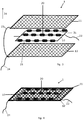
- the Figure 1 shows a first embodiment of a plasma generating device 1 in an exploded view.
- the plasma generating device 1 comprises a high-voltage electrode 10 surrounding a surface 30. In both directions of the normal to this enclosed surface 30 there is an outer electrode 11, 12 in each case.
- the two outer electrodes 11, 12 are connected to one another via an electrical connection 23.
- the high-voltage electrode 10 is designed as a wire in this example and is fed by the connecting line 22.
- the two outer electrodes 11, 12 are designed as metal mesh and are grounded via the ground cable 24.
- the high-voltage electrode 10 is encased with a dielectric 21 for a dielectrically impeded volume discharge.
- FIG. 3 Another embodiment in the exploded view shows Figure 3 .
- the flat high-voltage electrode 10 is bounded by a flat outer electrode 11, 12 in both directions of the normal to the surface 30 enclosed by the high-voltage electrode 10.
- the outer electrodes 11, 12 are also made of a metal mesh. Both outer electrodes 11, 12 are connected to one another by the electrical connection 23 and grounded via the ground cable 24.
- the Figure 4 shows the embodiment of the plasma generating device 1 in the applicable form.
- FIG Figure 5 An example of a linear embodiment of a plasma generating device according to the invention is shown in FIG Figure 5 .
- the wire-shaped high-voltage electrode 10 is covered with a dielectric 21.
- the tubular outer electrode 11 surrounds the high-voltage electrode 10 and is grounded via the ground cable 24.
- the equidistant distance 32 required for the dielectrically impeded volume discharge is given by the spacer elements 20.
- the atmospheric pressure plasma 33 generated for the dielectrically impeded volume discharge is located in the volume between the spacer elements 20, the grounded outer electrode 11 and the dielectric 21. From the coordinate direction 34 shown, it can be seen that the high-voltage electrode 10 at least in the coordinate direction 34 between the conductive material of the outer electrode 11 is arranged.
- FIG Figure 6 A further embodiment of the linear plasma generating device 1 is shown in FIG Figure 6 shown.
- the linear high-voltage electrode 10, which is coated with a dielectric 21, is surrounded by a spiral-shaped outer electrode 11. This spiral-shaped outer electrode 11 is grounded via the ground cable 24.
- the atmospheric pressure plasma 33 is generated in the spaces delimited by the outer electrode 11, the high-voltage electrode 10 and the individual spacer elements 20.
- a plasma generation system can be seen which has a plurality of plasma generation devices, in particular for the large-area treatment of surfaces.
- a plurality of plasma generation devices 1 are connected to one another in a cascade shape in an angular shape.
- the connections shown between the individual plasma generating devices 1 lead on the one hand to the high voltage, which is connected to the connecting line 22, and, on the other hand, to an earthed connection which is connected to the ground cable 24.
- ⁇ b> List of reference symbols ⁇ /b> Plasma generating device 1 High voltage electrode 10th First outer electrode 11 Second outer electrode 12 Spacer 20th dielectric 21st Connecting cable 22 Electrical connection 23 Ground cable 24th free section 25th Enclosed area 30th Parallel section 31 distance 32 Atmospheric pressure plasma 33 Coordinate direction 34
Landscapes
- Health & Medical Sciences (AREA)
- Engineering & Computer Science (AREA)
- Plasma & Fusion (AREA)
- Physics & Mathematics (AREA)
- Life Sciences & Earth Sciences (AREA)
- Veterinary Medicine (AREA)
- General Health & Medical Sciences (AREA)
- Animal Behavior & Ethology (AREA)
- Public Health (AREA)
- Biomedical Technology (AREA)
- Spectroscopy & Molecular Physics (AREA)
- Surgery (AREA)
- Molecular Biology (AREA)
- Epidemiology (AREA)
- Nuclear Medicine, Radiotherapy & Molecular Imaging (AREA)
- Medical Informatics (AREA)
- Heart & Thoracic Surgery (AREA)
- Otolaryngology (AREA)
- Chemical & Material Sciences (AREA)
- Medicinal Chemistry (AREA)
- Radiology & Medical Imaging (AREA)
- Plasma Technology (AREA)
- Electrotherapy Devices (AREA)
Description
Die vorliegende Anmeldung betrifft eine Plasmaerzeugungsvorrichtung mit einer Hochspannungselektrode sowie mindestens einer Außenelektrode. Des Weiteren betrifft die vorliegende Erfindung ein Plasmaerzeugungssystem mit mehreren erfindungsgemäßen Plasmaerzeugungsvorrichtungen, sowie ein Verfahren zur Erzeugung von Plasma mittels einer erfindungsgemäßen Plasmaerzeugungsvorrichtung oder einem erfindungsgemäßen Plasmaerzeugungssystem.The present application relates to a plasma generating device with a high-voltage electrode and at least one outer electrode. Furthermore, the present invention relates to a plasma generation system with a plurality of plasma generation devices according to the invention, and a method for generating plasma by means of a plasma generation device according to the invention or a plasma generation system according to the invention.
Die Plasmaerzeugungsvorrichtung dient insbesondere zur flächigen, antimikrobiellen Behandlung feuchter Oberflächen und bietet damit eine Möglichkeit der antimikrobiellen Wundbehandlung in feuchtem Milieu mittels spezieller Atmosphärendruckplasmaquellen.The plasma generating device is used in particular for flat, antimicrobial treatment of moist surfaces and thus offers a possibility of antimicrobial wound treatment in a moist environment by means of special atmospheric pressure plasma sources.
Atmosphärendruckplasmaquellen können für medizinische, zahnmedizinische oder kosmetische Zwecke eingesetzt werden. Übliche Plasmaerzeugungseinrichtungen sehen eine Superposition von Jet-Plasmen für die Abdeckung einer Fläche vor. Es werden dabei verschiedene Jet-Düsengeometrien genutzt.Atmospheric pressure plasma sources can be used for medical, dental or cosmetic purposes. Conventional plasma generating devices provide a superposition of jet plasmas for covering an area. Different jet nozzle geometries are used.
Neben der punktuellen Anwendung wird versucht, Plasmen auch flächig zu nutzen, wie zum Beispiel zur Behandlung von Wunden. Mit derartigen flächig ausgeführten Einrichtungen wird üblicherweise eine dielektrisch behinderte Entladung ("dielectric barrier discharge" - DBD) realisiert. Dabei unterscheidet man zwischen zwei unterschiedlichen Elektrodenkonfigurationen: einer Anordnung zur Erzeugung einer dielektrisch behinderten Oberflächenentladung (SBD), bei der die Elektroden beiderseits eines Dielektrikums direkt auf der Oberfläche des Dielektrikums angeordnet sind und das Plasma auf der Oberfläche des Dielektrikums ausgebildet wird, und einer Anordnung zur Erzeugung einer dielektrisch behinderten Volumenentladung (VBD), bei der die beiden Elektroden (mindestens eine mit einem Dielektrikum) in einem geringen Abstand voneinander angeordnet sind und sich das Plasma in diesem Raum zwischen den beiden Elektroden ausbildet.In addition to selective application, attempts are also made to use plasmas extensively, for example for treating wounds. A dielectric barrier discharge (DBD) is usually realized with such flat-type devices. A distinction is made between two different electrode configurations: an arrangement for generating a dielectrically impeded surface discharge (SBD), in which the electrodes are arranged on both sides of a dielectric directly on the surface of the dielectric and the plasma is formed on the surface of the dielectric, and an arrangement for Generation of a dielectric barrier volume discharge (VBD), in which the two electrodes (at least one with a dielectric) are arranged at a short distance from one another and the plasma is formed in this space between the two electrodes.
Derartige Einrichtungen sind meistens aus Festigkeitsgründen aus einem relativ festen bzw. starren Grundmaterial ausgeführt. Eine Anpassung an bestimmte Topografien ist daher nur eingeschränkt möglich.Such devices are usually made of a relatively solid or rigid base material for reasons of strength. An adaptation to certain topographies is therefore only possible to a limited extent.
Insbesondere Plasmaerzeugungseinrichtungen, die zur Anwendung im medizinischen Bereich ausgestaltet sind, unterliegen relativ strengen Vorschriften hinsichtlich der Sicherheit gegenüber einer drohenden, aus der anliegenden Hochspannung resultierenden Verletzungsgefahr sowie hinsichtlich der Einhaltung der Richtlinien der elektromagnetischen Verträglichkeit (EMV).In particular, plasma generating devices which are designed for use in the medical field are subject to relatively strict regulations with regard to safety against an impending high voltage resulting from the applied voltage Risk of injury and compliance with the guidelines for electromagnetic compatibility (EMC).
Eine flächige Plasmaerzeugungsvorrichtung ist beispielsweise aus der
Eine weitere Plasmaerzeugungsvorrichtung wird in der
Die Verwendung der oben genannten Plasmaerzeugungsvorrichtungen ist für die Wundheilung biologischer Gewebe in feuchtem Milieu nachteilig. Die Vorrichtungen der
Der Beeinträchtigung durch hohe Feuchtigkeit lässt sich durch die Verwendung einer dielektrisch behinderten Volumenentladung entgegenwirken. Eine auf einer dielektrisch behinderten Volumenentladung basierende Plasmaerzeugungsvorrichtung ist in der
Die Nutzung der zu behandelnden Oberfläche als geerdete Gegenelektrode birgt jedoch den Nachteil von unkontrollierbaren bzw. undefinierbaren Oberflächeneffekten auf dem zu behandelnden biologischen Gewebe. Ferner liegen die als Abstandshalter dienenden Noppen direkt auf der zu behandelnden Wunde und verursachen unerwünschte Reizungen oder rasterförmige Dekontaminationen.However, the use of the surface to be treated as a grounded counter electrode has the disadvantage of uncontrollable or indefinable surface effects on the biological tissue to be treated. Furthermore, the knobs serving as spacers lie directly on the wound to be treated and cause unwanted irritation or grid-shaped decontamination.
Die aus dem Stand der Technik bekannten Plasmaerzeugungsvorrichtungen mit flächigen Atmosphärendruck-Plasmaquellen weisen für die medizinische Nutzung Nachteile auf. Eine Nutzung von Atmosphärendruck-Plasmaquellen für medizinische, zahnmedizinische oder kosmetische Zwecke ist nur dann möglich, wenn die Einhaltung der Richtlinien der elektromagnetischen Verträglichkeit (EMV) gewährleistet werden kann. Bei den oben genannten flächigen Plasmaquellen ist die Störstrahlung durch die Plasmaquelle selbst nicht mehr zu vernachlässigen, die erforderlichen EMV-Anforderungen werden nicht erfüllt.The plasma generation devices with flat atmospheric pressure plasma sources known from the prior art have disadvantages for medical use. The use of atmospheric pressure plasma sources for medical, dental or cosmetic purposes is only possible if compliance with the guidelines for electromagnetic compatibility (EMC) can be guaranteed. In the case of the above-mentioned flat plasma sources, the interference radiation from the plasma source itself can no longer be neglected; the necessary EMC requirements are not met.
Der vorliegenden Erfindung liegt die Aufgabe zu Grunde, eine Plasmaerzeugungsvorrichtung, ein Plasmaerzeugungssystem sowie ein Verfahren zur Erzeugung von Plasma zur Verfügung zu stellen, mit denen in einfacher, kostengünstiger, sicherheitstechnisch unbedenklicher sowie flexibel anwendbarer Weise eine Behandlung von Oberflächen, insbesondere eine Desinfektion bzw. Sterilisation von Oberflächen wie z. B. auch von biologischem Gewebe, möglich ist.The present invention is based on the object of providing a plasma generating device, a plasma generating system and a method for generating plasma, with which treatment of surfaces, in particular disinfection or sterilization, can be carried out in a simple, cost-effective, safety-friendly and flexible manner of surfaces such. B. also of biological tissue is possible.
Diese Aufgabe wird durch die erfindungsgemäße Plasmaerzeugungsvorrichtung nach Anspruch 1 sowie durch das erfindungsgemäße Plasmaerzeugungssystem nach Anspruch 12 und durch das erfindungsgemäße Verfahren zur Erzeugung von Plasma nach Anspruch 13 gelöst. Vorteilhafte Ausgestaltungsformen der erfindungsgemäßen Plasmaerzeugungsvorrichtung sind in den Unteransprüchen 2 bis 11 angegeben.This object is achieved by the plasma generating device according to the invention according to
Die erfindungsgemäße Plasmaerzeugungsvorrichtung dient insbesondere zur Erzeugung eines Atmosphärendruckplasmas zur antimikrobiellen Behandlung feuchter Oberflächen. Die Plasmaerzeugungsvorrichtung umfasst eine Hochspannungselektrode sowie mindestens eine Außenelektrode, wobei die Hochspannungselektrode zumindest in einer Koordinatenrichtung zwischen Leitungsmaterial wenigstens einer Außenelektrode angeordnet ist. Die Hochspannungselektrode ist zumindest auf einer einer Außenelektrode zugewandten Seite mit einem Dielektrikum bedeckt. Gegebenenfalls ist die Hochspannungselektrode vollständig mit einem Dielektrikum bedeckt. Zwischen der jeweiligen Außenelektrode und der Hochspannungselektrode ist über deren Längserstreckung wenigstens ein Abstandselement angeordnet, welches zumindest im Bereich dessen Anordnung die jeweilige Außenelektrode von der Hochspannungselektrode elektrisch isoliert und in einem konstanten Abstand positioniert.The plasma generating device according to the invention is used in particular to generate an atmospheric pressure plasma for the antimicrobial treatment of moist surfaces. The plasma generating device comprises a high-voltage electrode and at least one outer electrode, the high-voltage electrode being arranged at least in a coordinate direction between line material of at least one outer electrode. The high-voltage electrode is covered with a dielectric at least on a side facing an outer electrode. The high-voltage electrode may be completely covered with a dielectric. Between the At least one spacer element is arranged over the longitudinal extension of the respective outer electrode and the high-voltage electrode, which at least in the area of its arrangement electrically insulates the respective outer electrode from the high-voltage electrode and positions it at a constant distance.
Das der Hochspannungselektrode in zumindest einer Koordinatenrichtung gegenüberliegende Leitungsmaterial der Außenelektrode dient bei Anlage einer geeigneten elektrischen Spannung an die Plasmaerzeugungsvorrichtung als die eigentliche Außenelektrode.The line material of the outer electrode, which is opposite the high-voltage electrode in at least one coordinate direction, serves as the actual outer electrode when a suitable electrical voltage is applied to the plasma generating device.
Vorzugsweise ist das Dielektrikum nicht nur an der der jeweiligen Außenelektrode zugewandten Seite der Hochspannungselektrode vorhanden, sondern umschließt die damit versehene Hochspannungselektrode.The dielectric is preferably not only present on the side of the high-voltage electrode facing the respective outer electrode, but encloses the high-voltage electrode provided with it.
Durch das Abstandselement bzw. durch die Anordnung mehrerer Abstandselemente wird eine im Wesentlichen äquidistante Anordnung der Elektroden zueinander realisiert. Daraus ergibt sich die Möglichkeit der Erzeugung einer dielektrisch behinderten Volumenentladung, die wesentlich stabiler gegenüber einem stark feuchten Milieu ist, sodass die erfindungsgemäße Plasmaerzeugungsvorrichtung insbesondere vorteilhaft an Wunden bzw. biologischen Geweben einsetzbar ist. Darüber hinaus wird durch die beidseitig der Hochspannungselektrode angeordnete Außenelektrode bzw. Außenelektroden eine wesentliche Reduzierung der von der Plasmaquelle abgestrahlten elektromagnetischen Störstrahlung erreicht.The spacer element or the arrangement of a plurality of spacer elements results in an essentially equidistant arrangement of the electrodes with respect to one another. This results in the possibility of generating a dielectrically impeded volume discharge which is considerably more stable than in a highly humid environment, so that the plasma generating device according to the invention can be used particularly advantageously on wounds or biological tissues. In addition, a substantial reduction in the electromagnetic interference radiation emitted by the plasma source is achieved by the outer electrode or outer electrodes arranged on both sides of the high-voltage electrode.
Die Hochspannungselektrode muss für den Hochvolt-(HV)-Bereich ausgebildet sein , nämlich für eine Spannung von mindestens 1 kV. In einer Ausgestaltung der erfindungsgemäßen Plasmaerzeugungsvorrichtung ist das Dielektrikum der Hochspannungselektrode für die doppelte Spannungsfestigkeit (also mindestens 2 kV) ausgelegt. Dabei kann die Plasmazeugungsvorrichtung für einen Spannungsbereich von 1 kV bis zu 25 kV eingerichtet sein, bei einer Frequenz der Wechselspannung von 1 kHz Kilohertz bis zu 1 Mhz, wobei die Ansteuerung sowohl mit Sinus-, Rechteck- oder Dreiecksignal als auch gepulst erfolgen kann.The high-voltage electrode must be designed for the high-voltage (HV) range, namely for a voltage of at least 1 kV. In one embodiment of the plasma generating device according to the invention, the dielectric of the high-voltage electrode is designed for twice the dielectric strength (that is to say at least 2 kV). The plasma generating device can be set up for a voltage range from 1 kV up to 25 kV, at a frequency of the AC voltage of 1 kHz kilohertz up to 1 Mhz, and the control can take place with a sine, square or triangular signal as well as in a pulsed manner.
Die Außenelektrode bzw. Außenelektroden sind geerdet ausgeführt. In einer Ausgestaltung der erfindungsgemäßen Plasmaerzeugungsvorrichtung umfasst diese eine erste Außenelektrode und eine zweite Außenelektrode, wobei die auch als Innenelektrode bezeichnete Hochspannungselektrode zwischen den beiden Außenelektroden angeordnet ist.The outer electrode or outer electrodes are grounded. In one embodiment of the plasma generating device according to the invention, it comprises a first outer electrode and a second outer electrode, the high-voltage electrode, also referred to as the inner electrode, being arranged between the two outer electrodes.
In diesem Fall ist die Hochspannungselektrode auf den den beiden Außenelektroden zugewandten Seiten mit einem Dielektrikum bedeckt.In this case, the high-voltage electrode is covered with a dielectric on the sides facing the two outer electrodes.
Die Hochspannungselektrode kann als ein Leitungselement ausgeführt sein, dessen Verhältnis der Länge zum Durchmesser wenigstens 10 beträgt. Ein solches dünnes Leitungselement kann ein isolierter dünner Draht oder auch ein isolierter, elektrisch leitender Faden sein.The high-voltage electrode can be designed as a line element, the ratio of the length to the diameter of which is at least 10. Such a thin conduction element can be an insulated thin wire or an insulated, electrically conductive thread.
Die Hochspannungselektrode kann als ein isolierter Draht ausgeführt sein, wobei die Isolation dabei gleichzeitig das Dielektrikum ausbildet.The high-voltage electrode can be designed as an insulated wire, the insulation simultaneously forming the dielectric.
In einer Ausgestaltung der Plasmaerzeugungsvorrichtung weist die Hochspannungselektrode einen mäanderförmigen oder spiralförmigen Verlauf auf.In one configuration of the plasma generating device, the high-voltage electrode has a meandering or spiral course.
In einer weiteren Ausführungsalternative kann die Hochspannungselektrode und/oder die Außenelektrode bzw. Außenelektroden als elektrisch leitfähiges textiles Material in Form eines Geflechts, Gewebes, Gewirkes oder Gestricktes oder auch ein Nähgewirk, Vliesstoff oder Filz oder eine Kombination dieser textilen Materialien sein, wobei das verwendete Material Metall oder auch lediglich eine Metallbeschichtung ist und im Fall der Hochspannungselektrode dieses Material mit einem Dielektrikum beschichtet ist.In a further alternative embodiment, the high-voltage electrode and / or the outer electrode or outer electrodes as an electrically conductive textile material in the form of a braid, woven fabric, knitted fabric or knitted fabric or else a sewing knitted fabric, non-woven fabric or felt or a combination of these textile materials, the material used Is metal or just a metal coating and in the case of the high voltage electrode this material is coated with a dielectric.
In einer weiteren Ausführungsform ist die Außenelektrode als elektrisch leitfähige Folie ausgebildet. Dabei ist die Folie insbesondere perforiert und/oder strukturiert ausgebildet.In a further embodiment, the outer electrode is designed as an electrically conductive film. The film is in particular perforated and / or structured.
Hinzukommend oder alternativ kann auch die Hochspannungselektrode als eine derartige, mit einem Dielektrikum beschichtete, Folie ausgestaltet sein.In addition or alternatively, the high-voltage electrode can also be designed as such a film coated with a dielectric.
Das jeweilige, die Hochspannungselektrode sowie auch die Außenelektrode oder Außenelektroden sowie ggf. auch das Dielektrikum, eine Isolation und die Abstandselemente ausbildende, Material kann einen Elastizitätsmodul von maximal 1 x10⁹ N/m2, insbesondere einen Elastizitätsmodul zwischen 0,1 x10⁹ N/m2 und 0,5 x10⁹ N/m2 aufweisen, sodass auch die gesamte Vorrichtung diesen Elastizitätsmodul und somit eine sehr geringe Biege- und/ oder Torsionssteifigkeit aufweist. Die Verwendung von elastischen oder flexiblen Materialien ermöglicht die flexible Anpassung der Plasmazeugungsvorrichtung an unterschiedlichste Topografien.The respective material which forms the high-voltage electrode and also the outer electrode or outer electrodes and possibly also the dielectric, insulation and the spacing elements can have an elastic modulus of at most 1 x 10 9 N / m 2 , in particular an elastic modulus between 0.1 x 10 9 N / m 2 and 0.5 x10 9 N / m 2 , so that the entire device also has this elastic modulus and thus a very low bending and / or torsional stiffness. The use of elastic or flexible materials allows the plasma generation device to be flexibly adapted to a wide variety of topographies.
Die Außenelektrode ist in einer Ausgestaltung der Plasmaerzeugungsvorrichtung als eine die Hochspannungselektrode einschließende, gasdurchlässige und flexible Elektrode ausgestaltet, wie z. B. als ein Metallgewebe oder auch ein anderes elektrisch leitfähiges, textiles Material oder eine perforierte, elektrisch leitende Elastomer-Folie bzw. eine mit einem elektrisch leitfähigen Material beschichtete Elastomer-Folie, wie z. B. eine Silikonfolie.In one embodiment of the plasma generating device, the outer electrode is designed as a gas-permeable and flexible electrode including the high-voltage electrode, such as, for. B. as a metal mesh or another electrically conductive, textile material or a perforated, electrically conductive elastomer film or an elastomer film coated with an electrically conductive material, such as. B. a silicone film.
Die Außenelektrode ist geerdet ausgeführt und kann auch ein Schlauch aus einem perforierten oder gewebten leitfähigen Material oder aus spiralförmig angeordnetem dünnen Edelstahl sein. Die in der erfindungsgemäßen Plasmaerzeugungsvorrichtung genutzten Außenelektroden sind leitfähig miteinander verbunden.The outer electrode is grounded and can also be a tube made of a perforated or woven conductive material or of spirally arranged thin stainless steel. The outer electrodes used in the plasma generating device according to the invention are conductively connected to one another.
In einer weiteren Ausführungsform der erfindungsgemäßen Plasmaerzeugungsvorrichtung ist vorgesehen, dass die Plasmaerzeugungsvorrichtung mehrere Abstandselemente aufweist, die als die Hochspannungselektrode zumindest abschnittsweise umschließende Isolierstücke ausgeführt sind. Derartige, auch Distanzstücke bezeichnete Abstandselemente können z. B. Silikonschlauchstücke sein. In einer Ausführungsform ist vorgesehen, dass ein Abstandselement oder auch mehrere Abstandselemente die Hochspannungselektrode über deren gesamten Verlauf umschließen.In a further embodiment of the plasma generating device according to the invention, it is provided that the plasma generating device has a plurality of spacer elements which are designed as insulating pieces which at least partially enclose the high-voltage electrode. Such spacers, also called spacers, can, for. B. pieces of silicone tubing. In one embodiment it is provided that one spacer element or also a plurality of spacer elements enclose the high-voltage electrode over its entire course.
In der Plasmaerzeugungsvorrichtung der vorliegenden Erfindung ist vorgesehen, dass das Abstandselement flächig ausgebildet ist. Das bedeutet, dass sich das Abstandselement im Wesentlichen in einer geraden Ebene erstreckt, sodass es die sich vorzugsweise ebenfalls in geraden, flächigen Ebenen erstreckenden Außenelektroden sowie die dazwischen aufgenommene Hochspannungselektrode voneinander separiert.In the plasma generating device of the present invention, it is provided that the spacer element is flat. This means that the spacer element extends essentially in a straight plane, so that it separates the outer electrodes, which preferably also extend in straight, flat planes, and the high-voltage electrode accommodated between them.
Das Abstandselement ist in der vorliegenden Erfindung durch eine perforierte und/oder strukturierte gasdurchlässige vorzugsweise flächendeckende Folie aus einem elektrisch nicht leitfähigen Elastomer realisiert. Solche Folie, wie z. B. eine Silikonfolie, kann auch als Dielektrikum verwendet werden, wobei eine drahtförmige Hochspannungselektrode, die z.B. auch als Geflecht, Gewebe, Gewirk oder Gestrick vorliegt, in diese Folie eingebettet ist.In the present invention, the spacer element is realized by a perforated and / or structured gas-permeable, preferably area-covering film made of an electrically non-conductive elastomer. Such film, such as. B. a silicon foil, can also be used as a dielectric, a wire-shaped high voltage electrode, e.g. is also present as braid, fabric, knitted fabric or knitted fabric, is embedded in this film.
Eine solche Folie kann Öffnungen aufweisen, sodass die als Dielektrikum dienende Folie eine Gasdurchlässigkeit aufweist. Die Öffnungen können durch eine Perforation hergestellt sein.Such a film can have openings so that the film serving as a dielectric has a gas permeability. The openings can be made by perforation.
Diese Ausgestaltung sollte die Folie insbesondere dann aufweisen, wenn die Folie flächendeckend zwischen Elektroden ausgeführt ist.The film should have this configuration in particular if the film is designed to cover the entire surface between electrodes.
In einer weiteren Ausführungsvariante der Plasmaerzeugungsvorrichtung ist vorgesehen, dass das Abstandselement als ein Geflecht, Gewebe, Gewirk oder Gestrick ausgebildet ist. Dadurch sind Öffnungen im Abstandselement integriert. Alternativ kann vorgesehen sein, dass auf einem solchen Abstandselement punktförmige oder rasterförmige Beschichtungen erzeugt sind, um den für eine dielektrisch behinderte Volumenentladung benötigten Abstand zwischen den Elektroden einhalten zu können.In a further embodiment variant of the plasma generating device, it is provided that the spacer element is designed as a braid, woven fabric, knitted fabric or knitted fabric. As a result, openings are integrated in the spacer element. Alternatively, it can be provided that punctiform or grid-shaped coatings are produced on such a spacer element in order to be able to maintain the distance between the electrodes required for a dielectrically impeded volume discharge.
In ergänzender Ausführungsform umfasst die erfindungsgemäße Plasmaerzeugungsvorrichtung eine Spannungsversorgungseinheit, die dazu eingerichtet ist, zwischen der Außenelektrode bzw. den Außenelektroden und der Hochspannungselektrode eine nieder- bis hochfrequente Hochspannung anzulegen.In a supplementary embodiment, the plasma generating device according to the invention comprises a voltage supply unit which is set up to apply a low to high frequency high voltage between the outer electrode or the outer electrodes and the high voltage electrode.
Vorteilhafte Ausgestaltungen der Plasmaerzeugungsvorrichtung hinsichtlich des Materials der Elektroden sowie auch hinsichtlich der Spannungsversorgungseinheit, der Zuleitungen und Anschlüsse der Leitungen an den Elektroden sind in den Dokumenten
Eine generelle Ausgestaltungsform der erfindungsgemäßen Plasmaerzeugungsvorrichtung besteht somit darin, dass die Plasmaerzeugungsvorrichtung im Wesentlichen flächig ausgeführt ist, wobei eine flächige Hochspannungselektrode sandwich-artig von zwei flächig ausgeführten Außenelektroden umgeben ist.A general embodiment of the plasma generating device according to the invention thus consists in the fact that the plasma generating device is essentially flat, with a flat high-voltage electrode being sandwiched by two flat outer electrodes.
Eine weitere Ausführungsform besteht in einer stab- bzw. rohrförmigen Ausgestaltung, wobei eine länglich erstreckte Hochspannungselektrode von einer wendel- bzw. schraubengangartig geformten Außenelektrode umgeben ist. Eine weitere Alternative besteht darin, dass eine längliche Hochspannungselektrode von einer rohrförmigen Außenelektrode aus einem gasdurchlässigen, elektrisch leitfähigen Material umgeben ist. Wird bei diesen Ausführungsformen flexibles Material verwendet, können diese spiral- oder mäanderförmig flächig angeordnet werden, so dass auch in diesen Fällen eine Anpassung an bestimmte Topografien möglich ist.A further embodiment consists of a rod-shaped or tubular design, an elongated high-voltage electrode being surrounded by a helical or screw-shaped outer electrode. Another alternative is that an elongated high-voltage electrode is surrounded by a tubular outer electrode made of a gas-permeable, electrically conductive material. If flexible material is used in these embodiments, these can be arranged in a spiral or meandering shape, so that an adaptation to certain topographies is also possible in these cases.
Allen Ausgestaltungsform ist gemeinsam, dass zwischen Hochspannungselektrode und Material der Außenelektrode Abstandselemente angeordnet sind, sodass jeweils ein Abstand besteht zwischen Hochspannungselektrode und Außenelektrode zur Realisierung einer dielektrisch behinderten Volumenentladung.It is common to all the embodiment that spacer elements are arranged between the high-voltage electrode and the material of the outer electrode, so that there is a distance between the high-voltage electrode and the outer electrode in order to realize a dielectrically impeded volume discharge.
Dadurch wird eine effektive, antimikrobielle Plasmabehandlung von Wunden und biologischen Geweben ermöglicht, sogar in einem sehr feuchten Milieu. Durch die beidseitig der Hochspannungselektrode angeordnete Außenelektrode oder Außenelektroden wird eine wesentliche Reduzierung der von der Plasmaquelle abgestrahlten elektromagnetischen Störstrahlung erreicht. Dies ermöglicht, auch für flächige Plasmaquellen die Bedingungen zur Einhaltung der Richtlinien der elektromagnetischen Verträglichkeit (EMV) zu erfüllen, sodass eine erfindungsgemäße Plasmavorrichtung auch für den Einsatz zu medizinischen, zahnmedizinischen und kosmetischen Zwecken zugelassen werden kann.This enables effective, antimicrobial plasma treatment of wounds and biological tissues, even in a very humid environment. A substantial reduction in the electromagnetic interference radiation emitted by the plasma source is achieved by the external electrode or external electrodes arranged on both sides of the high-voltage electrode. This enables the conditions for compliance with the guidelines for electromagnetic compatibility (EMC) to be met even for flat plasma sources, so that a plasma device according to the invention can also be approved for use for medical, dental and cosmetic purposes.
Im Gegensatz zu Plasmaquellen, die auf einer dielektrisch behinderten Oberflächenentladung basieren, bei denen die Ausbildung eines Plasmas auf der Oberfläche des Dielektrikums durch hohe Feuchtigkeit wesentlich beeinträchtigt oder sogar unterdrückt wird, ist die vorliegende Plasmaerzeugungsvorrichtung aufgrund der dielektrisch behinderten Volumenentladung wesentlich feuchtigkeitstauglicher und somit auch für die effektive, antimikrobielle Plasmabehandlung von Wunden und biologischen Geweben in sehr feuchtem Milieu geeignet.In contrast to plasma sources which are based on a dielectrically impeded surface discharge, in which the formation of a plasma on the surface of the dielectric is significantly impaired or even suppressed by high humidity, the present plasma generating device is considerably more moisture-compatible due to the dielectrically impeded volume discharge and thus also for the effective, antimicrobial plasma treatment of wounds and biological tissues in a very humid environment.
Im Gegensatz zu Plasmaquellen, die zwar die dielektrisch behinderte Volumenentladung ausführen, jedoch die Oberfläche des zu behandelnden biologischen Gewebes als geerdete Gegen- bzw. Außenelektrode nutzen und damit das Gewebe durch unkontrollierte bzw. undefinierte Oberflächeneffekte gefährden (wie z. B. im Fall eines elektrischen Durchschlags der Isolierung der Hochspannungselektrode), gewährleistet die erfindungsgemäße Plasmaerzeugungsvorrichtung durch die beidseitig der Hochspannungselektrode vorgesehene Anordnung wenigstens einer Außenelektrode die Eliminierung dieser Gefahr.In contrast to plasma sources, which carry out the dielectrically impeded volume discharge, but use the surface of the biological tissue to be treated as a grounded counter or outer electrode and thus the tissue through uncontrolled or Endanger undefined surface effects (such as in the case of an electrical breakdown of the insulation of the high-voltage electrode), the plasma generating device according to the invention ensures the elimination of this danger by arranging at least one outer electrode on both sides of the high-voltage electrode.
Zur optimalen Wundverträglichkeit kann die erfindungsgemäße Plasmaerzeugungsvorrichtung eine gasdurchlässige Wundauflage umfassen, die bei der Wundbehandlung zwischen biologischem Gewebe und der Plasmaerzeugungsvorrichtung zu positionieren ist. Eine derartige Wundauflage kann eine dünne, relativ weitmaschige textile Wundauflage (z.B. steriler Verbandsmull)sein. Derart wird verhindert, dass die Plasmaquelle direkt mit der Wunde in Kontakt kommt und es zu unerwünschten Reizungen oder auch zu einer Kontamination der Wunde wie bei der direkten Auflage nicht steriler Plasmaerzeugungsvorrichtungen kommt.For optimal wound tolerance, the plasma generation device according to the invention can comprise a gas-permeable wound dressing which is to be positioned between biological tissue and the plasma generation device during wound treatment. Such a wound dressing can be a thin, relatively wide-meshed textile wound dressing (e.g. sterile gauze). This prevents the plasma source from coming into direct contact with the wound and from causing unwanted irritation or contamination of the wound, as is the case with the direct application of non-sterile plasma generating devices.
Ein weiterer Aspekt der vorliegenden Erfindung ist ein Plasmaerzeugungssystem, welches insbesondere zur großflächigen Behandlung von Oberflächen, wie z. B. von Brandwunden, geeignet ist. Dieses Plasmaerzeugungssystem umfasst mehrere erfindungsgemäße Plasmaerzeugungsvorrichtungen sowie eine oder mehrere Spannungsversorgungseinheiten, die mit den Plasmaerzeugungsvorrichtungen elektrisch verbindbar oder verbunden sind.Another aspect of the present invention is a plasma generation system, which is particularly suitable for the large-area treatment of surfaces, such as. B. from burns is suitable. This plasma generation system comprises a plurality of plasma generation devices according to the invention and one or more voltage supply units which are or can be electrically connected to the plasma generation devices.
Insbesondere lassen sich die Plasmaerzeugungsvorrichtungen des Plasmaerzeugungssystems matrix-artig anordnen oder auch linear anordnen, um entsprechend geformte bzw. dimensionierte Oberflächenbereiche abdecken zu können. Es lassen sich somit mehrere erfindungsgemäße Plasmaerzeugungsvorrichtungen zu einer größeren Plasmaquelle zusammenfügen, um z. B. größere Hautbereiche von Brandopfern schnell, flexibel sowie medizinisch unbedenklich behandeln zu können. Zur Spannungsversorgung gibt es dabei die Möglichkeit, eine einzelne leistungsfähige Spannungsquelle als auch mehrere identische Spannungsquellen zur Versorgung eines einzelnen Flächenelementes und damit auch zur Versorgung einer jeweiligen Spannungserzeugungsvorrichtung zu verwenden.In particular, the plasma generating devices of the plasma generating system can be arranged in a matrix-like manner or also linearly in order to be able to cover appropriately shaped or dimensioned surface areas. Thus, several plasma generating devices according to the invention can be combined to form a larger plasma source in order, for. B. to treat large areas of the skin of burn victims quickly, flexibly and medically harmless. For the voltage supply there is the possibility of using a single powerful voltage source as well as several identical voltage sources for supplying an individual surface element and thus also for supplying a respective voltage generating device.
Die vorliegende Erfindung wird ergänzt durch ein Verfahren zur Erzeugung von Plasma, insbesondere zur Erzeugung einer dielektrisch behinderten Volumenentladung, bei der eine erfindungsgemäße Plasmaerzeugungsvorrichtung oder auch ein erfindungsgemäßes Plasmaerzeugungssystem zur Verfügung gestellt wird und eine elektrische Hochspannung an die Hochspannungselektrode und mindestens eine Außenelektrode angelegt wird. Dadurch lässt sich insbesondere eine Desinfektion von Oberflächen, wie z. B. Wunden menschlichen oder tierischen Gewebes, durchführen, bei dem das Verfahren zur Erzeugung von Plasma in einem solchen Abstand zur zu desinfizierenden Oberfläche durchgeführt wird, dass die zu desinfizierende Oberfläche mit den durch das Plasma erzeugten reaktiven Spezies des Plasmagases in Kontakt kommt.The present invention is supplemented by a method for generating plasma, in particular for generating a dielectrically impeded volume discharge, in which a plasma generation device according to the invention or a plasma generation system according to the invention is provided and an electrical high voltage is applied to the high voltage electrode and at least one outer electrode. This allows in particular a disinfection of surfaces such. B. wounds of human or animal tissue, in which the method for generating plasma is carried out at such a distance from the surface to be disinfected that the surface to be disinfected comes into contact with the reactive species of the plasma gas generated by the plasma.
Weitere Einzelheiten und Vorteile der vorliegenden Erfindung ergeben sich aus der nachfolgenden Beschreibung von Ausführungsbeispielen in Verbindung mit der Zeichnung.Further details and advantages of the present invention will become apparent from the following description of exemplary embodiments in conjunction with the drawing.
Die
Die
Die
Die
Die
Im anwendbaren Zustand ist die Plasmaerzeugungsvorrichtung 1 entsprechend der Darstellung in
Eine weitere Ausführungsform in der Explosionsdarstellung zeigt
Im Gegensatz zu dem in den
Die
Ein Beispiel für eine lineare Ausführung einer erfindungsgemäßen Plasmaerzeugungsvorrichtung zeigt die Schnittdarstellung in
Eine weitere Ausführung der linearen Plasmaerzeugungsvorrichtung 1 ist in
Die vorgenannten Ausführungsbeispiele beziehen sich auf die Ausführung einer einzelnen Plasmaerzeugungsvorrichtung 1. In
In diesem Plasmaerzeugungssystem sind mehrere Plasmaerzeugungsvorrichtungen 1 in eckiger Form miteinander kaskadenförmig verbunden. Die zwischen den einzelnen Plasmaerzeugungsvorrichtungen 1 gezeigten Verbindungen führen zum einen die Hochspannung, welche mit der Anschlussleitung 22 verbunden ist, und zum anderen eine geerdete Verbindung, die mit dem Massekabel 24 verbunden ist.
Claims (13)
- A plasma generating device (1)
comprising a high-voltage electrode (10) as well as at least one external electrode (11, 12), wherein the high-voltage electrode (10) is, at least in one coordinate direction (34), arranged between conductive material of at least one external electrode (11, 12) and the high-voltage electrode (10) is covered with a dielectric (21) at least on one side facing an external electrode (11, 12) of the plasma generating device (1), and wherein between the respective external electrode (11, 12) and the high-voltage electrode (10) over its longitudinal extension at least one spacer element (20) is present, which at least in the region of its arrangement electrically insulates the respective external electrode (11, 12) from the high-voltage electrode (10) and which positions the respective external electrode (11, 12) at a constant distance from the high-voltage electrode (10), characterized in that the spacer element (20) is planar in design, and the spacer element (20) is a perforated and/or structured, gas-permeable foil made of an electrically non-conductive elastomer. - The plasma generating device according to Claim 1, characterized in that the plasma generating device (1) comprises a first external electrode (11) and a second external electrode (12), wherein the high-voltage electrode (10) is arranged between the two external electrodes (11, 12).
- The plasma generating device according to any one of the preceding claims, characterized in that the high-voltage electrode (10) is configured as a wire.
- The plasma generating device according to any one of the preceding claims, characterized in that the high-voltage electrode (10) has a meandering or spiraling course.
- The plasma generating device according to any one of Claims 1 to 3, characterized in that the high-voltage electrode (10) is present as a mesh, woven fabric, knitted fabric or crocheted fabric.
- The plasma generating device according to any one of the preceding claims, characterized in that the external electrode (11, 12) is present as a mesh, woven fabric, knitted fabric or crocheted fabric.
- The plasma generating device according to any one of Claims 1 to 5, characterized in that the external electrode (11 and 12) is designed as an electrically conductive foil, in particular as a perforated and/or structured foil.
- The plasma generating device according to any one of the preceding claims, characterized in that the plasma generating device (1) has several spacer elements (20) which are configured as insulation pieces enclosing or covering the high-voltage electrode (10) at least in sections.
- The plasma generating device according to any one of the preceding claims, characterized in that the foil has openings.
- The plasma generating device according to any one of Claims 1 to 9, characterized in that the spacer element (20) is designed as a mesh, woven fabric, knitted fabric or crocheted fabric.
- The plasma generating device according to any one of the preceding claims, characterized in that the plasma generating device (1) has a voltage supply unit which is set up to apply a low to high-frequency high voltage between the external electrode and the high-voltage electrode.
- A plasma generating system, in particular for large-scale treatment of surfaces, comprising several plasma generating devices (1) according to any one of Claims 1 to 11 as well as one or more voltage supply units which are electrically connected or connectible to the plasma generating devices (1).
- A method for generating plasma, in which a plasma generating device according to any one of Claims 1 to 11 or a plasma generating system according to Claim 12 is provided and an electrical high voltage is applied to the high-voltage electrode and at least one external electrode.
Priority Applications (5)
| Application Number | Priority Date | Filing Date | Title |
|---|---|---|---|
| PT151950151T PT3171676T (en) | 2015-11-17 | 2015-11-17 | Plasma generating device, plasma generating system and method of generating plasma |
| DK15195015.1T DK3171676T3 (en) | 2015-11-17 | 2015-11-17 | PLASMA GENERATING DEVICE, PLASMA GENERATING SYSTEM AND METHOD OF PLASMA GENERATION |
| EP15195015.1A EP3171676B1 (en) | 2015-11-17 | 2015-11-17 | Plasma generating device, plasma generating system and method of generating plasma |
| ES15195015T ES2806033T3 (en) | 2015-11-17 | 2015-11-17 | Device for generating plasma, system for generating plasma and method for generating plasma |
| US15/352,630 US10307606B2 (en) | 2015-11-17 | 2016-11-16 | Device for generating plasma, system for generating plasma and method for generating plasma |
Applications Claiming Priority (1)
| Application Number | Priority Date | Filing Date | Title |
|---|---|---|---|
| EP15195015.1A EP3171676B1 (en) | 2015-11-17 | 2015-11-17 | Plasma generating device, plasma generating system and method of generating plasma |
Publications (2)
| Publication Number | Publication Date |
|---|---|
| EP3171676A1 EP3171676A1 (en) | 2017-05-24 |
| EP3171676B1 true EP3171676B1 (en) | 2020-06-24 |
Family
ID=54601644
Family Applications (1)
| Application Number | Title | Priority Date | Filing Date |
|---|---|---|---|
| EP15195015.1A Active EP3171676B1 (en) | 2015-11-17 | 2015-11-17 | Plasma generating device, plasma generating system and method of generating plasma |
Country Status (5)
| Country | Link |
|---|---|
| US (1) | US10307606B2 (en) |
| EP (1) | EP3171676B1 (en) |
| DK (1) | DK3171676T3 (en) |
| ES (1) | ES2806033T3 (en) |
| PT (1) | PT3171676T (en) |
Families Citing this family (14)
| Publication number | Priority date | Publication date | Assignee | Title |
|---|---|---|---|---|
| DE202009011521U1 (en) * | 2009-08-25 | 2010-12-30 | INP Greifswald Leibniz-Institut für Plasmaforschung und Technologie e. V. | Plasma cuff |
| DE102012207750A1 (en) * | 2012-05-09 | 2013-11-28 | Leibniz-Institut für Plasmaforschung und Technologie e.V. | APPARATUS FOR THE PLASMA TREATMENT OF HUMAN, ANIMAL OR VEGETABLE SURFACES, IN PARTICULAR OF SKIN OR TINIAL TIPS |
| US11684686B2 (en) * | 2016-02-04 | 2023-06-27 | Rutgers, The State University Of New Jersey | Flexible plasma applicators based on fibrous layers |
| US10646604B2 (en) * | 2016-02-04 | 2020-05-12 | Rutgers, The State University Of New Jersey | Flexible plasma applicators based on fibrous layers |
| DE102017100192A1 (en) * | 2017-01-06 | 2018-07-12 | Cinogy Gmbh | Permanent wound dressing with plasma electrode |
| KR101813558B1 (en) * | 2017-04-12 | 2018-01-03 | 주식회사 서린메디케어 | Skin treatment apparatus using fractional plasma |
| DE102017111902B4 (en) * | 2017-05-31 | 2020-12-31 | Cinogy Gmbh | Flat support arrangement |
| KR102037148B1 (en) * | 2017-09-18 | 2019-11-26 | 국방과학연구소 | Satellite-Shaped Flexible Plasma Generator |
| KR101920849B1 (en) | 2017-10-23 | 2018-11-21 | 국방과학연구소 | Plasma fabrics using flexible electrodes and manufacturing apparatus and method thereof |
| WO2019180257A1 (en) | 2018-03-23 | 2019-09-26 | Coldplasmatech Gmbh | Plasma applicator |
| CN109688689A (en) * | 2019-02-20 | 2019-04-26 | 北京卓昱科技有限公司 | A kind of broad gap electronic induction plasma generator |
| US11984309B1 (en) * | 2020-05-29 | 2024-05-14 | Microplasma Systems, Llc | Non-radioactive plasma ion source |
| NL2027148B1 (en) * | 2020-12-17 | 2022-07-11 | Plasmacure B V | Treatment pad for a dielectric barrier discharge plasma treatment |
| PL243915B1 (en) | 2021-01-14 | 2023-10-30 | Siec Badawcza Lukasiewicz Inst Mikroelektroniki I Fotoniki | Electrical system of a self-disinfecting touch keyboard |
Family Cites Families (10)
| Publication number | Priority date | Publication date | Assignee | Title |
|---|---|---|---|---|
| DE1130928B (en) * | 1960-11-17 | 1962-06-07 | Hydrawerk Ag | Electrolytic capacitor with reduced capacitance volume |
| EP1596047B1 (en) * | 2003-02-12 | 2008-01-09 | Ngk Insulators, Ltd. | Plasma reaction vessel, and method of producing the same |
| US20060013397A1 (en) * | 2004-07-13 | 2006-01-19 | International Business Machines Corporation | Channel adapter managed trusted queue pairs |
| CN1839996A (en) * | 2006-01-12 | 2006-10-04 | 上海现代中医药技术发展有限公司 | Chinese traditional medicine compound preparation for treating chronic hepatiosis and preparation method thereof |
| EP2297377B1 (en) * | 2008-05-30 | 2017-12-27 | Colorado State University Research Foundation | Plasma-based chemical source device and method of use thereof |
| DE202009011521U1 (en) * | 2009-08-25 | 2010-12-30 | INP Greifswald Leibniz-Institut für Plasmaforschung und Technologie e. V. | Plasma cuff |
| DE102009060627B4 (en) | 2009-12-24 | 2014-06-05 | Cinogy Gmbh | Electrode arrangement for a dielectrically impeded plasma treatment |
| DE102011105713B4 (en) * | 2011-06-23 | 2014-06-05 | Cinogy Gmbh | Electrode arrangement for a dielectrically impeded gas discharge |
| DE102012207750A1 (en) * | 2012-05-09 | 2013-11-28 | Leibniz-Institut für Plasmaforschung und Technologie e.V. | APPARATUS FOR THE PLASMA TREATMENT OF HUMAN, ANIMAL OR VEGETABLE SURFACES, IN PARTICULAR OF SKIN OR TINIAL TIPS |
| DE102013203648A1 (en) * | 2013-03-04 | 2014-09-04 | INP Greifswald Leibniz-Institut für Plasmaforschung und Technologie e. V. | METHOD AND DEVICE FOR PLASMA TREATMENT OF HOLLOW BODIES |
-
2015
- 2015-11-17 EP EP15195015.1A patent/EP3171676B1/en active Active
- 2015-11-17 DK DK15195015.1T patent/DK3171676T3/en active
- 2015-11-17 ES ES15195015T patent/ES2806033T3/en active Active
- 2015-11-17 PT PT151950151T patent/PT3171676T/en unknown
-
2016
- 2016-11-16 US US15/352,630 patent/US10307606B2/en active Active
Non-Patent Citations (1)
| Title |
|---|
| None * |
Also Published As
| Publication number | Publication date |
|---|---|
| US20170136252A1 (en) | 2017-05-18 |
| US10307606B2 (en) | 2019-06-04 |
| DK3171676T3 (en) | 2020-07-27 |
| ES2806033T3 (en) | 2021-02-16 |
| PT3171676T (en) | 2020-08-24 |
| EP3171676A1 (en) | 2017-05-24 |
Similar Documents
| Publication | Publication Date | Title |
|---|---|---|
| EP3171676B1 (en) | Plasma generating device, plasma generating system and method of generating plasma | |
| EP3079729B1 (en) | Assembly for the treatment of wounds | |
| EP3051926B1 (en) | Plasma generating device, plasma generating system, method of generating plasma and method for disinfecting surfaces | |
| EP2163143B1 (en) | Device for the treatment of surfaces with a plasma generated by an electrode over a solid dielectric via a dielectric barrier gas discharge | |
| EP3079765B1 (en) | Assembly for treating wounds | |
| EP3021875B1 (en) | System for reducing germs by means of plasma | |
| DE102012015483B3 (en) | Electrode arrangement for a plasma treatment and device for producing a transcutaneous connection | |
| WO2010025904A2 (en) | Method for treating a biological material comprising living cells | |
| DE102011001416A1 (en) | Plasma treatment device for treating surfaces e.g. wounds of skin i.e. forearm skin, of patient outside of hospitals, has oxygen reducing layer detachably secured on outer side of electrode, where outer side is turned away from surface | |
| EP2848097A1 (en) | Device for the plasma treatment of human, animal or plant surfaces, in particular of skin or mucous membrane areas | |
| DE102012103362A1 (en) | Pin-shaped plasma treatment apparatus for e.g. sterilization of skin or mucous membrane portion of human body, has electrode provided in pin part grounded in region of electrode, and another electrode provided on surface | |
| EP3329747B1 (en) | Electrode arrangement and plasma-treatment apparatus for surface-treating a body | |
| EP3148464B1 (en) | Device for biologically decontaminating percutaneous access points and method therefor | |
| WO2014040630A1 (en) | Plasma treatment device with flexible surface electrodes | |
| EP3429640A1 (en) | Device, system, and method for antimicrobial treatment, method for producing the device, and computer program | |
| DE102016205821B4 (en) | Plasma source for wound treatment | |
| DE102019006536B3 (en) | Device and method for skin and in particular wound treatment using plasma | |
| WO2012136370A1 (en) | Plasma device | |
| WO2000074105A1 (en) | X-ray tube and catheter having such an x-ray tube |
Legal Events
| Date | Code | Title | Description |
|---|---|---|---|
| PUAI | Public reference made under article 153(3) epc to a published international application that has entered the european phase |
Free format text: ORIGINAL CODE: 0009012 |
|
| STAA | Information on the status of an ep patent application or granted ep patent |
Free format text: STATUS: THE APPLICATION HAS BEEN PUBLISHED |
|
| AK | Designated contracting states |
Kind code of ref document: A1 Designated state(s): AL AT BE BG CH CY CZ DE DK EE ES FI FR GB GR HR HU IE IS IT LI LT LU LV MC MK MT NL NO PL PT RO RS SE SI SK SM TR |
|
| AX | Request for extension of the european patent |
Extension state: BA ME |
|
| STAA | Information on the status of an ep patent application or granted ep patent |
Free format text: STATUS: REQUEST FOR EXAMINATION WAS MADE |
|
| 17P | Request for examination filed |
Effective date: 20171123 |
|
| RBV | Designated contracting states (corrected) |
Designated state(s): AL AT BE BG CH CY CZ DE DK EE ES FI FR GB GR HR HU IE IS IT LI LT LU LV MC MK MT NL NO PL PT RO RS SE SI SK SM TR |
|
| STAA | Information on the status of an ep patent application or granted ep patent |
Free format text: STATUS: EXAMINATION IS IN PROGRESS |
|
| 17Q | First examination report despatched |
Effective date: 20191212 |
|
| GRAP | Despatch of communication of intention to grant a patent |
Free format text: ORIGINAL CODE: EPIDOSNIGR1 |
|
| STAA | Information on the status of an ep patent application or granted ep patent |
Free format text: STATUS: GRANT OF PATENT IS INTENDED |
|
| INTG | Intention to grant announced |
Effective date: 20200325 |
|
| GRAS | Grant fee paid |
Free format text: ORIGINAL CODE: EPIDOSNIGR3 |
|
| GRAA | (expected) grant |
Free format text: ORIGINAL CODE: 0009210 |
|
| STAA | Information on the status of an ep patent application or granted ep patent |
Free format text: STATUS: THE PATENT HAS BEEN GRANTED |
|
| RAP1 | Party data changed (applicant data changed or rights of an application transferred) |
Owner name: LEIBNIZ-INSTITUT FUER PLASMAFORSCHUNG UND TECHNOLOGIE E.V. |
|
| AK | Designated contracting states |
Kind code of ref document: B1 Designated state(s): AL AT BE BG CH CY CZ DE DK EE ES FI FR GB GR HR HU IE IS IT LI LT LU LV MC MK MT NL NO PL PT RO RS SE SI SK SM TR |
|
| REG | Reference to a national code |
Ref country code: GB Ref legal event code: FG4D Free format text: NOT ENGLISH |
|
| REG | Reference to a national code |
Ref country code: CH Ref legal event code: EP |
|
| REG | Reference to a national code |
Ref country code: DE Ref legal event code: R096 Ref document number: 502015012848 Country of ref document: DE |
|
| REG | Reference to a national code |
Ref country code: AT Ref legal event code: REF Ref document number: 1285215 Country of ref document: AT Kind code of ref document: T Effective date: 20200715 |
|
| REG | Reference to a national code |
Ref country code: NO Ref legal event code: T2 Effective date: 20200624 Ref country code: FI Ref legal event code: FGE |
|
| REG | Reference to a national code |
Ref country code: IE Ref legal event code: FG4D Free format text: LANGUAGE OF EP DOCUMENT: GERMAN |
|
| REG | Reference to a national code |
Ref country code: DK Ref legal event code: T3 Effective date: 20200722 |
|
| REG | Reference to a national code |
Ref country code: PT Ref legal event code: SC4A Ref document number: 3171676 Country of ref document: PT Date of ref document: 20200824 Kind code of ref document: T Free format text: AVAILABILITY OF NATIONAL TRANSLATION Effective date: 20200810 |
|
| REG | Reference to a national code |
Ref country code: SE Ref legal event code: TRGR |
|
| PG25 | Lapsed in a contracting state [announced via postgrant information from national office to epo] |
Ref country code: LT Free format text: LAPSE BECAUSE OF FAILURE TO SUBMIT A TRANSLATION OF THE DESCRIPTION OR TO PAY THE FEE WITHIN THE PRESCRIBED TIME-LIMIT Effective date: 20200624 Ref country code: GR Free format text: LAPSE BECAUSE OF FAILURE TO SUBMIT A TRANSLATION OF THE DESCRIPTION OR TO PAY THE FEE WITHIN THE PRESCRIBED TIME-LIMIT Effective date: 20200925 |
|
| REG | Reference to a national code |
Ref country code: LT Ref legal event code: MG4D |
|
| PG25 | Lapsed in a contracting state [announced via postgrant information from national office to epo] |
Ref country code: HR Free format text: LAPSE BECAUSE OF FAILURE TO SUBMIT A TRANSLATION OF THE DESCRIPTION OR TO PAY THE FEE WITHIN THE PRESCRIBED TIME-LIMIT Effective date: 20200624 Ref country code: LV Free format text: LAPSE BECAUSE OF FAILURE TO SUBMIT A TRANSLATION OF THE DESCRIPTION OR TO PAY THE FEE WITHIN THE PRESCRIBED TIME-LIMIT Effective date: 20200624 Ref country code: BG Free format text: LAPSE BECAUSE OF FAILURE TO SUBMIT A TRANSLATION OF THE DESCRIPTION OR TO PAY THE FEE WITHIN THE PRESCRIBED TIME-LIMIT Effective date: 20200924 Ref country code: RS Free format text: LAPSE BECAUSE OF FAILURE TO SUBMIT A TRANSLATION OF THE DESCRIPTION OR TO PAY THE FEE WITHIN THE PRESCRIBED TIME-LIMIT Effective date: 20200624 |
|
| REG | Reference to a national code |
Ref country code: NL Ref legal event code: MP Effective date: 20200624 |
|
| PG25 | Lapsed in a contracting state [announced via postgrant information from national office to epo] |
Ref country code: AL Free format text: LAPSE BECAUSE OF FAILURE TO SUBMIT A TRANSLATION OF THE DESCRIPTION OR TO PAY THE FEE WITHIN THE PRESCRIBED TIME-LIMIT Effective date: 20200624 Ref country code: NL Free format text: LAPSE BECAUSE OF FAILURE TO SUBMIT A TRANSLATION OF THE DESCRIPTION OR TO PAY THE FEE WITHIN THE PRESCRIBED TIME-LIMIT Effective date: 20200624 |
|
| PG25 | Lapsed in a contracting state [announced via postgrant information from national office to epo] |
Ref country code: CZ Free format text: LAPSE BECAUSE OF FAILURE TO SUBMIT A TRANSLATION OF THE DESCRIPTION OR TO PAY THE FEE WITHIN THE PRESCRIBED TIME-LIMIT Effective date: 20200624 Ref country code: RO Free format text: LAPSE BECAUSE OF FAILURE TO SUBMIT A TRANSLATION OF THE DESCRIPTION OR TO PAY THE FEE WITHIN THE PRESCRIBED TIME-LIMIT Effective date: 20200624 Ref country code: SM Free format text: LAPSE BECAUSE OF FAILURE TO SUBMIT A TRANSLATION OF THE DESCRIPTION OR TO PAY THE FEE WITHIN THE PRESCRIBED TIME-LIMIT Effective date: 20200624 |
|
| REG | Reference to a national code |
Ref country code: ES Ref legal event code: FG2A Ref document number: 2806033 Country of ref document: ES Kind code of ref document: T3 Effective date: 20210216 |
|
| PG25 | Lapsed in a contracting state [announced via postgrant information from national office to epo] |
Ref country code: SK Free format text: LAPSE BECAUSE OF FAILURE TO SUBMIT A TRANSLATION OF THE DESCRIPTION OR TO PAY THE FEE WITHIN THE PRESCRIBED TIME-LIMIT Effective date: 20200624 Ref country code: PL Free format text: LAPSE BECAUSE OF FAILURE TO SUBMIT A TRANSLATION OF THE DESCRIPTION OR TO PAY THE FEE WITHIN THE PRESCRIBED TIME-LIMIT Effective date: 20200624 Ref country code: IS Free format text: LAPSE BECAUSE OF FAILURE TO SUBMIT A TRANSLATION OF THE DESCRIPTION OR TO PAY THE FEE WITHIN THE PRESCRIBED TIME-LIMIT Effective date: 20201024 |
|
| REG | Reference to a national code |
Ref country code: DE Ref legal event code: R097 Ref document number: 502015012848 Country of ref document: DE |
|
| PLBE | No opposition filed within time limit |
Free format text: ORIGINAL CODE: 0009261 |
|
| STAA | Information on the status of an ep patent application or granted ep patent |
Free format text: STATUS: NO OPPOSITION FILED WITHIN TIME LIMIT |
|
| 26N | No opposition filed |
Effective date: 20210325 |
|
| PG25 | Lapsed in a contracting state [announced via postgrant information from national office to epo] |
Ref country code: MC Free format text: LAPSE BECAUSE OF FAILURE TO SUBMIT A TRANSLATION OF THE DESCRIPTION OR TO PAY THE FEE WITHIN THE PRESCRIBED TIME-LIMIT Effective date: 20200624 |
|
| PG25 | Lapsed in a contracting state [announced via postgrant information from national office to epo] |
Ref country code: LU Free format text: LAPSE BECAUSE OF NON-PAYMENT OF DUE FEES Effective date: 20201117 |
|
| REG | Reference to a national code |
Ref country code: BE Ref legal event code: MM Effective date: 20201130 |
|
| PG25 | Lapsed in a contracting state [announced via postgrant information from national office to epo] |
Ref country code: SI Free format text: LAPSE BECAUSE OF FAILURE TO SUBMIT A TRANSLATION OF THE DESCRIPTION OR TO PAY THE FEE WITHIN THE PRESCRIBED TIME-LIMIT Effective date: 20200624 |
|
| PG25 | Lapsed in a contracting state [announced via postgrant information from national office to epo] |
Ref country code: IE Free format text: LAPSE BECAUSE OF NON-PAYMENT OF DUE FEES Effective date: 20201117 |
|
| PG25 | Lapsed in a contracting state [announced via postgrant information from national office to epo] |
Ref country code: TR Free format text: LAPSE BECAUSE OF FAILURE TO SUBMIT A TRANSLATION OF THE DESCRIPTION OR TO PAY THE FEE WITHIN THE PRESCRIBED TIME-LIMIT Effective date: 20200624 Ref country code: MT Free format text: LAPSE BECAUSE OF FAILURE TO SUBMIT A TRANSLATION OF THE DESCRIPTION OR TO PAY THE FEE WITHIN THE PRESCRIBED TIME-LIMIT Effective date: 20200624 Ref country code: CY Free format text: LAPSE BECAUSE OF FAILURE TO SUBMIT A TRANSLATION OF THE DESCRIPTION OR TO PAY THE FEE WITHIN THE PRESCRIBED TIME-LIMIT Effective date: 20200624 |
|
| PG25 | Lapsed in a contracting state [announced via postgrant information from national office to epo] |
Ref country code: MK Free format text: LAPSE BECAUSE OF FAILURE TO SUBMIT A TRANSLATION OF THE DESCRIPTION OR TO PAY THE FEE WITHIN THE PRESCRIBED TIME-LIMIT Effective date: 20200624 |
|
| PG25 | Lapsed in a contracting state [announced via postgrant information from national office to epo] |
Ref country code: EE Free format text: LAPSE BECAUSE OF FAILURE TO SUBMIT A TRANSLATION OF THE DESCRIPTION OR TO PAY THE FEE WITHIN THE PRESCRIBED TIME-LIMIT Effective date: 20200624 Ref country code: BE Free format text: LAPSE BECAUSE OF NON-PAYMENT OF DUE FEES Effective date: 20201130 |
|
| P01 | Opt-out of the competence of the unified patent court (upc) registered |
Effective date: 20230601 |
|
| PGFP | Annual fee paid to national office [announced via postgrant information from national office to epo] |
Ref country code: GB Payment date: 20231123 Year of fee payment: 9 |
|
| PGFP | Annual fee paid to national office [announced via postgrant information from national office to epo] |
Ref country code: ES Payment date: 20231215 Year of fee payment: 9 |
|
| PGFP | Annual fee paid to national office [announced via postgrant information from national office to epo] |
Ref country code: SE Payment date: 20231123 Year of fee payment: 9 Ref country code: PT Payment date: 20231107 Year of fee payment: 9 Ref country code: NO Payment date: 20231121 Year of fee payment: 9 Ref country code: IT Payment date: 20231130 Year of fee payment: 9 Ref country code: FR Payment date: 20231124 Year of fee payment: 9 Ref country code: FI Payment date: 20231120 Year of fee payment: 9 Ref country code: DK Payment date: 20231122 Year of fee payment: 9 Ref country code: DE Payment date: 20231120 Year of fee payment: 9 Ref country code: CH Payment date: 20231202 Year of fee payment: 9 Ref country code: AT Payment date: 20231117 Year of fee payment: 9 |