EP3165365A1 - Sheet-fed stamping press comprising a foil laminating unit - Google Patents
Sheet-fed stamping press comprising a foil laminating unit Download PDFInfo
- Publication number
- EP3165365A1 EP3165365A1 EP15193276.1A EP15193276A EP3165365A1 EP 3165365 A1 EP3165365 A1 EP 3165365A1 EP 15193276 A EP15193276 A EP 15193276A EP 3165365 A1 EP3165365 A1 EP 3165365A1
- Authority
- EP
- European Patent Office
- Prior art keywords
- stamping
- cylinder
- foil
- counter
- sheet
- Prior art date
- Legal status (The legal status is an assumption and is not a legal conclusion. Google has not performed a legal analysis and makes no representation as to the accuracy of the status listed.)
- Withdrawn
Links
- 239000011888 foil Substances 0.000 title claims abstract description 128
- 238000010030 laminating Methods 0.000 title 1
- 239000000463 material Substances 0.000 claims abstract description 52
- 238000003825 pressing Methods 0.000 claims abstract description 46
- 238000003475 lamination Methods 0.000 claims abstract description 4
- 238000012423 maintenance Methods 0.000 claims description 4
- 229920002635 polyurethane Polymers 0.000 claims description 4
- 239000004814 polyurethane Substances 0.000 claims description 4
- 238000011144 upstream manufacturing Methods 0.000 claims description 4
- 239000011248 coating agent Substances 0.000 claims description 3
- 238000000576 coating method Methods 0.000 claims description 3
- 239000013013 elastic material Substances 0.000 claims description 3
- 229920001971 elastomer Polymers 0.000 claims description 3
- 230000008901 benefit Effects 0.000 description 2
- 238000001816 cooling Methods 0.000 description 2
- 230000007547 defect Effects 0.000 description 2
- 238000004519 manufacturing process Methods 0.000 description 2
- 239000011159 matrix material Substances 0.000 description 2
- 238000004804 winding Methods 0.000 description 2
- 230000009471 action Effects 0.000 description 1
- 239000000969 carrier Substances 0.000 description 1
- 238000010276 construction Methods 0.000 description 1
- 230000001419 dependent effect Effects 0.000 description 1
- 238000010586 diagram Methods 0.000 description 1
- 230000003116 impacting effect Effects 0.000 description 1
- 230000003993 interaction Effects 0.000 description 1
- 238000012986 modification Methods 0.000 description 1
- 230000004048 modification Effects 0.000 description 1
- 239000005871 repellent Substances 0.000 description 1
- 238000000926 separation method Methods 0.000 description 1
Images


Classifications
-
- B—PERFORMING OPERATIONS; TRANSPORTING
- B41—PRINTING; LINING MACHINES; TYPEWRITERS; STAMPS
- B41F—PRINTING MACHINES OR PRESSES
- B41F16/00—Transfer printing apparatus
- B41F16/0006—Transfer printing apparatus for printing from an inked or preprinted foil or band
- B41F16/002—Presses of the rotary type
- B41F16/0026—Presses of the rotary type with means for applying print under heat and pressure, e.g. using heat activable adhesive
-
- B—PERFORMING OPERATIONS; TRANSPORTING
- B31—MAKING ARTICLES OF PAPER, CARDBOARD OR MATERIAL WORKED IN A MANNER ANALOGOUS TO PAPER; WORKING PAPER, CARDBOARD OR MATERIAL WORKED IN A MANNER ANALOGOUS TO PAPER
- B31F—MECHANICAL WORKING OR DEFORMATION OF PAPER, CARDBOARD OR MATERIAL WORKED IN A MANNER ANALOGOUS TO PAPER
- B31F1/00—Mechanical deformation without removing material, e.g. in combination with laminating
- B31F1/07—Embossing, i.e. producing impressions formed by locally deep-drawing, e.g. using rolls provided with complementary profiles
-
- B—PERFORMING OPERATIONS; TRANSPORTING
- B41—PRINTING; LINING MACHINES; TYPEWRITERS; STAMPS
- B41F—PRINTING MACHINES OR PRESSES
- B41F16/00—Transfer printing apparatus
- B41F16/0006—Transfer printing apparatus for printing from an inked or preprinted foil or band
- B41F16/0013—Transfer printing apparatus for printing from an inked or preprinted foil or band combined with other printing presses
-
- B—PERFORMING OPERATIONS; TRANSPORTING
- B41—PRINTING; LINING MACHINES; TYPEWRITERS; STAMPS
- B41F—PRINTING MACHINES OR PRESSES
- B41F16/00—Transfer printing apparatus
- B41F16/0006—Transfer printing apparatus for printing from an inked or preprinted foil or band
- B41F16/0066—Printing dies or forms
-
- B—PERFORMING OPERATIONS; TRANSPORTING
- B41—PRINTING; LINING MACHINES; TYPEWRITERS; STAMPS
- B41F—PRINTING MACHINES OR PRESSES
- B41F19/00—Apparatus or machines for carrying out printing operations combined with other operations
-
- B—PERFORMING OPERATIONS; TRANSPORTING
- B41—PRINTING; LINING MACHINES; TYPEWRITERS; STAMPS
- B41F—PRINTING MACHINES OR PRESSES
- B41F19/00—Apparatus or machines for carrying out printing operations combined with other operations
- B41F19/001—Apparatus or machines for carrying out printing operations combined with other operations with means for coating or laminating
-
- B—PERFORMING OPERATIONS; TRANSPORTING
- B41—PRINTING; LINING MACHINES; TYPEWRITERS; STAMPS
- B41P—INDEXING SCHEME RELATING TO PRINTING, LINING MACHINES, TYPEWRITERS, AND TO STAMPS
- B41P2219/00—Printing presses using a heated printing foil
- B41P2219/50—Printing presses using a heated printing foil combined with existing presses
Definitions
- the present invention generally relates to a sheet-fed stamping press. More precisely, the present invention relates to a sheet-fed stamping press as defined in the preamble of claim 1 hereof.
- the present invention is in particular applicable for the production of security documents, such as banknotes.
- Sheet-fed stamping presses especially such stamping presses that are adapted to carry out hot-stamping of foil material are known in the art, for instance from International ( PCT) Publications Nos. WO 97/35721 A1 , WO 97/35794 A1 , WO 97/35795 A1 , WO 97/36756 A1 , WO 03/043823 A1 , WO 2005/102733 A2 and WO 2008/104904 A1 , which publications are incorporated herein by reference in their entirety.
- FIG. 1 is an illustration of a known sheet-fed stamping press, designated globally by reference numeral 10, as discussed in the aforementioned publications.
- This sheet-fed stamping press 10 is designed for performing hot-stamping of foil material onto successive sheets S which are fed from a sheet feeder 1 supplying individual sheets S in succession from a sheet feeding pile 15 for processing in a downstream-located foil application unit 2.
- This foil application unit 2 is designed in the present illustration to allow transfer by hot-stamping of foil material onto the successive sheets S, which foil material is conventionally fed to the foil application unit 2 in the form of a continuous band by means of a foil feeding system 3. More precisely, the foil material to be transferred onto the sheets S is provided on a suitable foil carrier FC, which is brought into contact with the surface of the sheets S so as to allow transfer of the foil material from the foil carrier FC onto the sheets S under the combined application of heat and pressure.
- FC suitable foil carrier FC
- the foil application unit 2 could be adapted to allow lamination of foil material as for instance disclosed in International ( PCT) Publication No. WO 2008/104904 A1 (see also International ( PCT) Publications Nos. WO 2009/112989 A1 and WO 2010/001317 A1 , which are likewise incorporated herein by reference in their entirety).
- the foil carrier FC is laminated onto the sheets S as part of the applied foil material.
- the foil application unit 2 comprises a heated stamping cylinder 21 with at least one, usually multiple circumferential stamping sections 210 (see Figure 2 ) that are provided on a circumference of the stamping cylinder 21.
- the stamping cylinder 21 actually comprises a plurality of (namely six) circumferential stamping sections 210 that are provided on the circumference of the stamping cylinder and distributed axially along an axis of rotation of the stamping cylinder 21 (i.e. along direction x in Figure 2 ) at a plurality of axial positions, which axial positions correspond to different columns of security imprints that are present on the sheets S.
- Each circumferential stamping section 210 actually comprises successive stamping segments 211 that are distributed one after the other about the circumference of the stamping cylinder 21 (i.e. along the circumferential direction y in Figure 2 ).
- the stamping cylinder 21 is a four-segment cylinder and each stamping section 210 accordingly comprises four such stamping segments 211, which are conventionally designed as individual stamping segments that are secured at both ends in corresponding cylinder pits 21 b as discussed in greater detail in International ( PCT) Publication No. WO 2005/102733 A2 .
- sheet holding units 21a are distributed about the circumference of the stamping cylinder 21 in order to hold a leading edge of each successive sheet S that is fed to the stamping cylinder 21.
- These sheet holding units 21a can in particular be configured as suction units that are designed to hold the leading edge of a sheet S by suction.
- the sheet holding units 21a are integrated into a number of bridge elements 215 that are provided and secured in the cylinder pits 21 b as illustrated in Figure 2 and discussed in greater detail in International ( PCT) Publication No. WO 2005/102733 A2 .
- the foil carrier FC is typically fed to the foil application unit 2 by means of the foil feeding system 3 that comprises one or more supply rolls 31 for the supply of the foil carrier FC and one or more winding-up rolls 32 for winding up used foil carrier, designated by reference numeral FC*.
- the particular structure of the foil feeding system 3 is not of major relevance in the context of the instant invention. It suffices to understand that the foil feeding system 3 is adapted to supply the foil carrier FC in register with the sheets S. More detailed information regarding the structure and operation of the foil feeding system 3 can be found for instance in International ( PCT) Publication No. WO 94/13487 A1 , which is incorporated herein by reference in its entirety.
- the foil carrier FC is fed from the foil feeding system 3 to the stamping cylinder 21 between the circumferential stamping sections 210 and the sheets S that are fed from the sheet feeder 1.
- multiple counter-pressure rollers 22 are provided about a portion of the circumference of the stamping cylinder 21. More precisely, the counter-pressure rollers 22 are arranged in pairs and distributed about a lower portion of the circumference of the stamping cylinder 21 so as to press the underside of the sheet S against the circumference of the stamping cylinder 21 and thereby ensure application of a suitable pressure between the foil carrier FC and the sheet S to cause transfer of the foil material from its carrier FC onto the sheet S. This transfer is also ensured through the application of heat applied via the stamping cylinder 21 that is heated up to a suitable temperature.
- the pairs of counter-pressure rollers 22 are typically constructed as individual counter-pressure unit each comprising its own pneumatic (or hydraulic) cylinder or piston 23 designed to press the counter-pressure rollers 22 against the circumference of the stamping cylinder 21, or more exactly against the circumference of the circumferential stamping sections 210.
- European Patent Publication No. EP 0 582 178 A1 and International ( PCT) Publication No. WO 2005/120832 A1 which are incorporated herein by reference in their entirety, disclose further details of counter-pressure roller systems for stamping presses.
- each stamping segment 211 of the circumferential stamping sections 210 typically comprises corresponding stamping surface(s) 211a, which come into contact with the foil carrier FC, as well as supporting tracks 211 b located on either side of the stamping surface(s) 211 a, which come into contact with the sheets S, outside of the region where the foil carrier FC is present, so as to provide continuous support for the counter-pressure rollers 22.
- the supporting tracks 211b are aligned with the bridge elements 215 so as to provide uninterrupted support for the counter-pressure rollers 22 across the region of the cylinder pits 21 b.
- each stamping segment 211 includes a plurality of individual stamping surfaces 211 a, which is typical for the application of individual patches of foil material onto the sheets S.
- each stamping segment 211 would typically include a single, continuous stamping surface 211 a to cause transfer of a corresponding continuous stripe of foil material onto the sheets S.
- a conveyor system 4 for conveying the sheets S and foil carrier FC, which is still attached to the sheets S, away from the stamping cylinder 21.
- This conveyor system 4 conventionally comprises conveyor belts or bands 41 and a cooling roller 42 about the circumference of which the sheets S and foil carrier FC are brought in order to cool-down the sheets S and foil carrier FC and thereby enhance adhesion of the foil material onto the sheets S prior to separation of the foil carrier FC.
- a foil detachment device 45 is also typically provided along the path of the conveyor system 4 so as to separate the foil carrier FC from the sheets S.
- the used foil carrier FC* is then wound up around the winding-up roll(s) 32 or possibly fed again upstream of the foil application unit 2 (which is typically done in case of patch application - see again International (PCT) Publication No. WO 94/13487 A1 ).
- a suction drum 46 that works in conjunction with a downstream-located chain-gripper system to transport and deliver the processed sheets, designated by reference numeral S* for the sake of distinction, in a sheet delivery unit 5 of the stamping press 10.
- the chain-gripper system consists of chain wheels 51, 52 driving a pair of endless chains 53 extending therebetween and holding spaced-apart gripper bars 54 designed to hold the processed sheets S* by a leading edge thereof and transport the processed sheets S* individually in order to be delivered on top of a sheet delivery pile 55. More than one delivery pile 55 may be provided.
- a problem with the aforementioned sheet-fed stamping press resides in the fact that the counter-pressure rollers 22, which are pressed against the underside of the sheets S exert a braking force on the sheets S, which braking force may cause undesired movement or slippage of the sheets S with respect to the circumference of the stamping cylinder 21. Such movement or slippage of the sheets S in turn causes stress on the foil carrier FC and/or affects a proper register of the foil material with respect to the sheets S, which is not desired.
- a general aim of the invention is therefore to improve the known sheet-fed stamping presses.
- an aim of the present invention is to provide such a sheet-fed stamping press where sheet transport and foil application are improved.
- a sheet-fed stamping press comprising a foil application unit designed to allow transfer or lamination of foil material onto successive sheets, which foil material is fed to the foil application unit in the form of a foil carrier supplied by means of a foil feeding system.
- the foil application unit comprises a stamping cylinder with at least one circumferential stamping section provided on a circumference of the stamping cylinder and comprising successive stamping segments distributed one after the other about the circumference of the stamping cylinder, the stamping cylinder also acting as sheet-transporting cylinder and comprising multiple sheet holding units distributed about the circumference of the stamping cylinder and designed to hold successive sheets against the circumference of the stamping cylinder.
- the foil application unit further comprises a plurality of counter-pressure units distributed about a portion of the circumference of the stamping cylinder and designed to press the successive sheets and the foil carrier against an outer surface of the stamping segments, the foil carrier being supplied by the foil feeding system between the sheets and the stamping segments.
- each counter-pressure unit is designed as a cylinder unit provided with at least one circumferential pressing element positioned to cooperate with the circumferential stamping section of the stamping cylinder, and the counter-pressure units are driven into rotation by means of at least one dedicated drive.
- the counter-pressure units are driven into rotation by means of a common drive.
- each counter-pressure unit is driven into rotation by means of a separate drive.
- a rotational speed or angular position of each counter-pressure unit is adjustable with respect to a rotational speed or angular position of the stamping cylinder, which helps adjusting operation of the counter-pressure units to improve transport of the sheets and ensure optimal transfer of the foil material from the foil carrier onto the sheets.
- the stamping cylinder is configured to comprise a plurality of the circumferential stamping sections provided on the circumference of the stamping cylinder, which circumferential stamping sections are distributed axially along an axis of rotation of the stamping cylinder at a plurality of axial positions.
- each counter-pressure unit is provided with a plurality of the circumferential pressing elements that are distributed axially along an axis of rotation of the cylinder unit at a plurality of axial positions corresponding to the axial positions of the circumferential stamping sections of the stamping cylinder.
- the foil feeding system is adapted to supply the foil carrier at a plurality of axial positions corresponding to the axial positions of the circumferential stamping sections.
- Each stamping segment can comprise one or more stamping surfaces coming into contact with corresponding portions of the foil carrier.
- each stamping segment comprises a continuous stamping surface designed to allow application of a continuous stripe of foil material onto the successive sheets.
- each stamping segment comprises one or more individual stamping surfaces designed to allow application of one or more corresponding portions of foil material onto the successive sheets.
- a distance of each counter-pressure unit with respect to the circumference of the stamping cylinder is adjustable, which can conveniently be achieved by mounting each counter-pressure unit on eccentric bearings.
- Such adjustment of the distance of the counter-pressure units with respect to the circumference of the stamping cylinder is particular advantageous in that supporting tracks on the stamping segments that typically come into contact with the successive sheets outside of the region where the foil carrier is present are no more required and can therefore be omitted.
- a ratio of a nominal diameter of each circumferential stamping section of the stamping cylinder over a nominal diameter of each circumferential pressing element of the counter-pressure units is an integer multiple.
- each circumferential pressing element is designed as a pressing ring that is supported on a common shaft of the counter-pressure unit.
- each pressing ring of the counter-pressure units may advantageously comprise an outer annular supporting portion, which comes into contact with the successive sheets, and an inner portion made of a compressible elastic material, which is located on an inner side of the outer annular supporting portion, which can help to absorb slight variations in the thickness of the circumferential stamping sections.
- the outer annular supporting portion can conveniently be made of or coated with a material having a pressure resistance of more than 100 N/mm2, preferably greater than 300 N/mm2.
- a suitable material is in particular Gesadur® of company Korröder GmbH & Co. KG in Wuppertal, Germany (Gesadur® being a registered trademark of Fa. G.H. Soröder).
- the counter-pressure units are mounted on a movable carriage that is retractable away from the stamping cylinder during maintenance operations, the movable carriage being preferably slidable along a direction parallel to an axis of rotation of the stamping cylinder.
- a first one of the counter-pressure units located at an upstream end with respect to a direction of rotation of the stamping cylinder is provided with an outer coating made of a deformable material, such as rubber or polyurethane.
- the present invention will be described in the particular context of a sheet-fed stamping press for the production of security documents, such as banknotes.
- the sheets are typically provided with a matrix arrangement of multiple security imprints printed on the sheets.
- FIG 3 is a schematic diagram of a sheet-fed stamping press 10* in accordance with a preferred embodiment of the invention.
- Relevant subgroups of the sheet-fed stamping press 10* are basically identical to corresponding subgroups of the sheet-fed stamping press 10 shown in Figure 1 , namely the sheet feeder 1, the foil feeding system 3, the conveyor system 4 and the delivery unit 5.
- Components of the stamping press 10* of Figure 3 that are designated by the same reference numerals as in Figure 1 will not be described again, it being to be appreciated that some of these components are not directly impacting the invention.
- the construction of the conveyor system 4 and delivery unit 5 shown schematically in Figure 3 does not directly affect the invention and other solutions could be contemplated in order to ensure transfer of the sheets S and foil carrier FC away from the stamping cylinder 21 of the stamping press 10*.
- the stamping press 10* of Figure 3 is in particular characterized in that it comprises a foil application unit, designated by reference numeral 2*, including a stamping cylinder 21 that is basically similar to the stamping cylinder 21 of Figure 1 .
- This stamping cylinder 21 is likewise provided with at least one circumferential stamping section 210 provided on a circumference of the stamping cylinder 21 and comprising successive stamping segments 211* or 211** (shown schematically in Figures 4a and 4b ) distributed one after the other about the circumference of the stamping cylinder 21.
- the stamping cylinder 21 is a four-segment cylinder and acts as sheet-transporting cylinder.
- the stamping cylinder 21 therefore likewise comprises multiple sheet holding units 21a distributed about the circumference of the stamping cylinder 21 and designed to hold the successive sheets S against the circumference of the stamping cylinder 21.
- a main difference resides in the structure and operation of the counter-pressure system that cooperates with the stamping cylinder 21 and is used to exert pressure on the sheets S.
- multiple counter-pressure units 25 are distributed about a portion of the circumference of the stamping cylinder 21. These counter-pressure units 25 are designed to press the successive sheets S and the foil carrier FC against the outer surface of the stamping segments 211* / 211**.
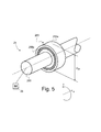
- each counter-pressure unit 25 is designed as a cylinder unit 250/255 (see Figure 5 ) that is provided with at least one circumferential pressing element 255 - namely as many circumferential pressing elements 255 as there are circumferential stamping sections 210 - positioned to cooperate with the circumferential stamping section 210 of the stamping cylinder 21.
- the circumferential pressing elements 255 of each counter-pressure unit 25 are preferably designed as pressing rings that are supported on a common shaft 250.
- an axial position of each pressing ring along the common shaft 250 is advantageously adjustable so as to allow positioning of each circumferential pressing element 255 in dependence of the axial positions of the circumferential stamping sections 210 on the stamping cylinder 21.
- the circumferential pressing elements 255 could be designed as multiple pressing sections provided on the circumference of a suitable sleeve or plate member mounted on a cylinder body acting as counter-pressure unit 25.
- the sleeve or plate member could for instance be provided with a number of relief portions acting as circumferential pressing elements and made of a material suitable for that purpose.
- Such material could in particular be Gesadur® material as commercially available from company Gambröder GmbH & Co. KG in Wuppertal, Germany (Gesadur® being a registered trademark of Fa. G.H. Soröder).
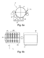
- each counter-pressure unit 25 is likewise provided with a plurality of circumferential pressing elements 255 that are distributed axially along an axis of rotation of the cylinder unit 250/255 at a plurality of axial positions corresponding to the axial positions of the circumferential stamping sections 210 of the stamping cylinder 21 (see e.g. Figure 6b ).
- the foil feeding system 3 is adapted to feed multiple foil carriers FC at a plurality of axial positions corresponding to the axial positions of the circumferential stamping sections 210.
- the counter-pressure units 25 are driven into rotation by means of at least one dedicated drive.
- This can be a common drive driving all counter-pressure units 25 or, preferably, as schematically illustrated in Figure 3 , separate drives 26, such as servo-motors, each driving a corresponding one of the counter-pressure units 25.
- a rotational speed or angular position of each counter-pressure unit 25 is adjustable with respect to a rotational speed or angular position of the stamping cylinder 21. This helps adjusting operation of the counter-pressure units 25 to improve transport of the sheets S and ensure optimal transfer of the foil material from the foil carrier FC onto the sheets S. This also allows adequate repositioning - if need be - of the individual counter-pressure units 25 from one stamping segment 211* / 211** to the next.
- each stamping segment 211* / 211** comprises one or more stamping surfaces 211a* / 211a** coming into contact with corresponding portions of the foil carrier FC corresponding to the foil material to be transferred onto the sheets S.
- Figure 4a shows a structure of a stamping segment 211* used for stripe application.
- the stamping segment 211* comprises a continuous stamping surface 211a* designed to allow application of a continuous stripe of foil material onto the successive sheets S.
- Figure 4b shows a structure of a stamping segment 211** used for patch application.
- the stamping segment 211a** comprises one or more individual stamping surfaces 211a** designed to allow application of one or more corresponding portions (or patches) of foil material onto the successive sheets S.
- six individual stamping surfaces 211 a** are provided, which would be convenient for patch application onto sheets S carrying six rows of security imprints. It will understood that the number and position of the relevant stamping surfaces depends on the particular layout of the sheets S to be processed.
- a distance of each counter-pressure unit 25 with respect to the circumference of the stamping cylinder 21 is adjustable. That is, each counter-pressure unit 25 is not pressed against the circumference of the stamping cylinder 21 under the action of any pneumatic or hydraulic system as in the known solutions, but a position of each counter-pressure unit 25 per se with respect to the circumference of the stamping cylinder 21 is adjusted. In other words, the resulting pressure exerted by each counter-pressure unit 25 is dependent on the actual position of the cylinder unit 250/255 with respect to the stamping cylinder 21 and the combined thickness of the sheets S and foil carrier FC that are interposed between the counter-pressure unit 25 and the stamping cylinder 21.
- Such adjustment of the distance of the counter-pressure unit 25 with respect to the circumference of the stamping cylinder 21 is preferably achieved through mounting of each counter-pressure unit on suitable eccentric bearings that are schematically illustrated and designated in Figure 3 by reference numeral 27.
- An adjustment in position of the counter-pressure units 25 with respect to the circumference of the stamping cylinder 21 is especially advantageous in that it does not require the provision of supporting tracks (like the supporting tracks 211 b shown in Figure 2 ) on the stamping segments 211* / 211**, as illustrated in Figures 4a and 4b . Indeed, a continuous support of the cylinder unit 250/255 against the circumference of the stamping cylinder 21 (or more precisely against the circumference of the circumferential stamping sections 210) is not anymore required in such a case.
- a ratio of a nominal diameter D 21 of each circumferential stamping section 210 of the stamping cylinder 21 over a nominal diameter D 25 of each circumferential pressing element 255 of the counter-pressure units 25 is preferably and advantageously an integer multiple.
- this ratio D 21 /D 25 is equal to 4. This is particularly advantageous in that there is a one-to-one relationship between the circumference of the circumferential pressing element(s) 255 and each segment of the stamping cylinder 21, i.e.
- each point of the circumference of the circumferential pressing element(s) 255 always corresponds to a same point on the surface of the sheets (assuming that the stamping cylinder 21 and counter-pressure unit 25 are rotated in synchronism or repositioned at the start of each stamping segment 211* / 211**). There is therefore no risk that any undesired transfer of residues from the sheets S (such as ink residues) on the surface of the circumferential pressing element(s) 255 is transferred back onto a different location of the sheets S, which could otherwise cause undesired quality defects on the sheets S.
- each pressing ring (acting as circumferential pressing element 255) of the counter-pressure units 25 advantageously comprises an outer annular supporting portion 255a, which comes into contact with the successive sheets S, and an inner portion 255b made of a compressible elastic material, which is located on an inner side of the outer annular supporting portion 255a.
- the outer annular supporting portion 255a may advantageously be made of or coated with a material having a pressure resistance of more than 100 N/mm 2 , preferably greater than 300 N/mm 2 .
- a suitable material in this context is Gesadur® material as commercially available from company Soröder GmbH & Co.
- Gesadur® material is ideally suited in the context of the present invention in view of its material properties, in particular in terms of stability, durability and dirt-repellent properties.
- the counter-pressure units 25 are advantageously mounted (together with the associated drives 26) on a movable carriage 28 that is retractable away from the stamping cylinder 21 during maintenance operations.
- the movable carriage 28 is slidable along a direction parallel to an axis of rotation of the stamping cylinder 21 (i.e.
- reference numeral 28* designates the moveable carriage 28 moved in a retracted position away from the stamping cylinder 21.
- At least the first one of the counter-pressure units 25 located at the upstream end with respect to a direction of rotation of the stamping cylinder 21 may be provided with an outer coating made of a deformable material, such as rubber or polyurethane (instead of the configuration illustrated in Figure 5 ), so as to properly press the sheets S against the circumference of the stamping cylinder 21 and force evacuation of air that may be trapped between the sheets S, the foil carrier FC and the relevant stamping surfaces 211a* / 211a** of the circumferential stamping segments 211* / 211**, thereby improving application of the foil material onto the surface of the sheets S.
- Suitable polyurethane materials can in particular be obtained commercially from company Felix Böttcher GmbH & Co. KG (http://www.boettcher.de ).
- circumferential pressing elements could take any suitable form, in particular be designed as multiple pressing sections provided on the circumference of a suitable sleeve or plate member mounted on a cylinder body acting as counter-pressure unit as mentioned above.
Landscapes
- Engineering & Computer Science (AREA)
- Mechanical Engineering (AREA)
- Treatment Of Fiber Materials (AREA)
- Absorbent Articles And Supports Therefor (AREA)
- Machines For Manufacturing Corrugated Board In Mechanical Paper-Making Processes (AREA)
- Delivering By Means Of Belts And Rollers (AREA)
- Perforating, Stamping-Out Or Severing By Means Other Than Cutting (AREA)
- Printing Methods (AREA)
- Laminated Bodies (AREA)
Abstract
There is described a sheet-fed stamping press (10*) comprising a foil application unit (2*) designed to allow transfer or lamination of foil material onto successive sheets (S), which foil material is fed to the foil application unit (2*) in the form of a foil carrier (FC) supplied by means of a foil feeding system (3). The foil application unit (2*) comprises a stamping cylinder (21) with circumferential stamping sectionS (210) provided on a circumference of the stamping cylinder (21) and comprising successive stamping segments (211*; 211**) distributed one after the other about the circumference of the stamping cylinder (21), the stamping cylinder (21) also acting as sheet-transporting cylinder and comprising multiple sheet holding units (21 a) distributed about the circumference of the stamping cylinder (21) and designed to hold successive sheets (S) against the circumference of the stamping cylinder (21). The foil application unit (2*) further comprises a plurality of counter-pressure units (25) distributed about a portion of the circumference of the stamping cylinder (21) and designed to press the successive sheets (S) and the foil carrier (FC) against an outer surface of the stamping segments (211*; 211**), the foil carrier (FC) being supplied by the foil feeding system (3) between the sheets (S) and the stamping segments (211*; 211**). Each counter-pressure unit (25) is designed as a cylinder unit (250, 255) provided with at least one circumferential pressing element (255) positioned to cooperate with the circumferential stamping sections (210) of the stamping cylinder (21), and the counter-pressure units (25) are driven into rotation by means of at least one dedicated drive (26).
Description
- The present invention generally relates to a sheet-fed stamping press. More precisely, the present invention relates to a sheet-fed stamping press as defined in the preamble of
claim 1 hereof. The present invention is in particular applicable for the production of security documents, such as banknotes. - Sheet-fed stamping presses, especially such stamping presses that are adapted to carry out hot-stamping of foil material are known in the art, for instance from International (
PCT) Publications Nos. WO 97/35721 A1 WO 97/35794 A1 WO 97/35795 A1 WO 97/36756 A1 WO 03/043823 A1 WO 2005/102733 A2 andWO 2008/104904 A1 , which publications are incorporated herein by reference in their entirety. -
Figure 1 is an illustration of a known sheet-fed stamping press, designated globally byreference numeral 10, as discussed in the aforementioned publications. This sheet-fedstamping press 10 is designed for performing hot-stamping of foil material onto successive sheets S which are fed from asheet feeder 1 supplying individual sheets S in succession from asheet feeding pile 15 for processing in a downstream-locatedfoil application unit 2. Thisfoil application unit 2 is designed in the present illustration to allow transfer by hot-stamping of foil material onto the successive sheets S, which foil material is conventionally fed to thefoil application unit 2 in the form of a continuous band by means of afoil feeding system 3. More precisely, the foil material to be transferred onto the sheets S is provided on a suitable foil carrier FC, which is brought into contact with the surface of the sheets S so as to allow transfer of the foil material from the foil carrier FC onto the sheets S under the combined application of heat and pressure. - Alternatively, the
foil application unit 2 could be adapted to allow lamination of foil material as for instance disclosed in International (PCT) Publication No. WO 2008/104904 A1 PCT) Publications Nos. WO 2009/112989 A1 WO 2010/001317 A1 , which are likewise incorporated herein by reference in their entirety). In this case, at least a part of the foil carrier FC is laminated onto the sheets S as part of the applied foil material. - The
foil application unit 2 comprises a heatedstamping cylinder 21 with at least one, usually multiple circumferential stamping sections 210 (seeFigure 2 ) that are provided on a circumference of the stampingcylinder 21. In the illustrated example, one will appreciate that the stampingcylinder 21 actually comprises a plurality of (namely six)circumferential stamping sections 210 that are provided on the circumference of the stamping cylinder and distributed axially along an axis of rotation of the stamping cylinder 21 (i.e. along direction x inFigure 2 ) at a plurality of axial positions, which axial positions correspond to different columns of security imprints that are present on the sheets S. Eachcircumferential stamping section 210 actually comprisessuccessive stamping segments 211 that are distributed one after the other about the circumference of the stamping cylinder 21 (i.e. along the circumferential direction y inFigure 2 ). In the illustrated example, thestamping cylinder 21 is a four-segment cylinder and eachstamping section 210 accordingly comprises foursuch stamping segments 211, which are conventionally designed as individual stamping segments that are secured at both ends incorresponding cylinder pits 21 b as discussed in greater detail in International (PCT) Publication No. WO 2005/102733 A2 - As shown in
Figures 1 and2 , four sets ofsheet holding units 21a are distributed about the circumference of thestamping cylinder 21 in order to hold a leading edge of each successive sheet S that is fed to the stampingcylinder 21. Thesesheet holding units 21a can in particular be configured as suction units that are designed to hold the leading edge of a sheet S by suction. In the illustrated example, thesheet holding units 21a are integrated into a number ofbridge elements 215 that are provided and secured in thecylinder pits 21 b as illustrated inFigure 2 and discussed in greater detail in International (PCT) Publication No. WO 2005/102733 A2 - The foil carrier FC is typically fed to the
foil application unit 2 by means of thefoil feeding system 3 that comprises one ormore supply rolls 31 for the supply of the foil carrier FC and one or more winding-uprolls 32 for winding up used foil carrier, designated by reference numeral FC*. The particular structure of thefoil feeding system 3 is not of major relevance in the context of the instant invention. It suffices to understand that thefoil feeding system 3 is adapted to supply the foil carrier FC in register with the sheets S. More detailed information regarding the structure and operation of thefoil feeding system 3 can be found for instance in International (PCT) Publication No. WO 94/13487 A1 - In the aforementioned stamping press, it will be understood that the foil carrier FC is fed from the
foil feeding system 3 to the stampingcylinder 21 between thecircumferential stamping sections 210 and the sheets S that are fed from thesheet feeder 1. - As illustrated in
Figure 1 ,multiple counter-pressure rollers 22 are provided about a portion of the circumference of the stampingcylinder 21. More precisely, thecounter-pressure rollers 22 are arranged in pairs and distributed about a lower portion of the circumference of the stampingcylinder 21 so as to press the underside of the sheet S against the circumference of thestamping cylinder 21 and thereby ensure application of a suitable pressure between the foil carrier FC and the sheet S to cause transfer of the foil material from its carrier FC onto the sheet S. This transfer is also ensured through the application of heat applied via the stampingcylinder 21 that is heated up to a suitable temperature. The pairs ofcounter-pressure rollers 22 are typically constructed as individual counter-pressure unit each comprising its own pneumatic (or hydraulic) cylinder or piston 23 designed to press thecounter-pressure rollers 22 against the circumference of the stampingcylinder 21, or more exactly against the circumference of thecircumferential stamping sections 210. European Patent Publication No.EP 0 582 178 A1PCT) Publication No. WO 2005/120832 A1 - In the aforementioned context, as illustrated in
Figure 2 , eachstamping segment 211 of thecircumferential stamping sections 210 typically comprises corresponding stamping surface(s) 211a, which come into contact with the foil carrier FC, as well as supportingtracks 211 b located on either side of the stamping surface(s) 211 a, which come into contact with the sheets S, outside of the region where the foil carrier FC is present, so as to provide continuous support for thecounter-pressure rollers 22. As shown inFigure 2 , the supportingtracks 211b are aligned with thebridge elements 215 so as to provide uninterrupted support for thecounter-pressure rollers 22 across the region of thecylinder pits 21 b. In the illustration ofFigure 2 , eachstamping segment 211 includes a plurality ofindividual stamping surfaces 211 a, which is typical for the application of individual patches of foil material onto the sheets S. In the event of a stripe application, eachstamping segment 211 would typically include a single,continuous stamping surface 211 a to cause transfer of a corresponding continuous stripe of foil material onto the sheets S. - Downstream of the
foil application unit 2, there is typically provided aconveyor system 4 for conveying the sheets S and foil carrier FC, which is still attached to the sheets S, away from the stampingcylinder 21. Thisconveyor system 4 conventionally comprises conveyor belts orbands 41 and acooling roller 42 about the circumference of which the sheets S and foil carrier FC are brought in order to cool-down the sheets S and foil carrier FC and thereby enhance adhesion of the foil material onto the sheets S prior to separation of the foil carrier FC. Afoil detachment device 45 is also typically provided along the path of theconveyor system 4 so as to separate the foil carrier FC from the sheets S. The used foil carrier FC* is then wound up around the winding-up roll(s) 32 or possibly fed again upstream of the foil application unit 2 (which is typically done in case of patch application - see again International (PCT)Publication No. WO 94/13487 A1 - At a downstream end of the
conveyor system 4, there is typically provided asuction drum 46 that works in conjunction with a downstream-located chain-gripper system to transport and deliver the processed sheets, designated by reference numeral S* for the sake of distinction, in asheet delivery unit 5 of thestamping press 10. More precisely, the chain-gripper system consists ofchain wheels endless chains 53 extending therebetween and holding spaced-apartgripper bars 54 designed to hold the processed sheets S* by a leading edge thereof and transport the processed sheets S* individually in order to be delivered on top of asheet delivery pile 55. More than onedelivery pile 55 may be provided. - A problem with the aforementioned sheet-fed stamping press resides in the fact that the
counter-pressure rollers 22, which are pressed against the underside of the sheets S exert a braking force on the sheets S, which braking force may cause undesired movement or slippage of the sheets S with respect to the circumference of the stampingcylinder 21. Such movement or slippage of the sheets S in turn causes stress on the foil carrier FC and/or affects a proper register of the foil material with respect to the sheets S, which is not desired. - There is therefore a need to improve the known sheet-fed stamping presses.
- A general aim of the invention is therefore to improve the known sheet-fed stamping presses.
- More precisely, an aim of the present invention is to provide such a sheet-fed stamping press where sheet transport and foil application are improved.
- These aims are achieved thanks to the sheet-fed stamping press defined in the claims.
- There is accordingly provided a sheet-fed stamping press comprising a foil application unit designed to allow transfer or lamination of foil material onto successive sheets, which foil material is fed to the foil application unit in the form of a foil carrier supplied by means of a foil feeding system. The foil application unit comprises a stamping cylinder with at least one circumferential stamping section provided on a circumference of the stamping cylinder and comprising successive stamping segments distributed one after the other about the circumference of the stamping cylinder, the stamping cylinder also acting as sheet-transporting cylinder and comprising multiple sheet holding units distributed about the circumference of the stamping cylinder and designed to hold successive sheets against the circumference of the stamping cylinder. The foil application unit further comprises a plurality of counter-pressure units distributed about a portion of the circumference of the stamping cylinder and designed to press the successive sheets and the foil carrier against an outer surface of the stamping segments, the foil carrier being supplied by the foil feeding system between the sheets and the stamping segments. According to the invention, each counter-pressure unit is designed as a cylinder unit provided with at least one circumferential pressing element positioned to cooperate with the circumferential stamping section of the stamping cylinder, and the counter-pressure units are driven into rotation by means of at least one dedicated drive.
- Preferably, the counter-pressure units are driven into rotation by means of a common drive. Alternatively, each counter-pressure unit is driven into rotation by means of a separate drive.
- Advantageously, a rotational speed or angular position of each counter-pressure unit is adjustable with respect to a rotational speed or angular position of the stamping cylinder, which helps adjusting operation of the counter-pressure units to improve transport of the sheets and ensure optimal transfer of the foil material from the foil carrier onto the sheets.
- In the context of an application where the sheets are provided with a matrix arrangement of multiple security imprints printed on the sheets comprising multiple columns of imprints, the stamping cylinder is configured to comprise a plurality of the circumferential stamping sections provided on the circumference of the stamping cylinder, which circumferential stamping sections are distributed axially along an axis of rotation of the stamping cylinder at a plurality of axial positions. Additionally, each counter-pressure unit is provided with a plurality of the circumferential pressing elements that are distributed axially along an axis of rotation of the cylinder unit at a plurality of axial positions corresponding to the axial positions of the circumferential stamping sections of the stamping cylinder. Furthermore, the foil feeding system is adapted to supply the foil carrier at a plurality of axial positions corresponding to the axial positions of the circumferential stamping sections.
- Each stamping segment can comprise one or more stamping surfaces coming into contact with corresponding portions of the foil carrier. In one example, each stamping segment comprises a continuous stamping surface designed to allow application of a continuous stripe of foil material onto the successive sheets. In another example, each stamping segment comprises one or more individual stamping surfaces designed to allow application of one or more corresponding portions of foil material onto the successive sheets.
- In accordance with a particularly preferred embodiment of the invention, a distance of each counter-pressure unit with respect to the circumference of the stamping cylinder is adjustable, which can conveniently be achieved by mounting each counter-pressure unit on eccentric bearings.
- Such adjustment of the distance of the counter-pressure units with respect to the circumference of the stamping cylinder is particular advantageous in that supporting tracks on the stamping segments that typically come into contact with the successive sheets outside of the region where the foil carrier is present are no more required and can therefore be omitted.
- In accordance with another advantageous embodiment of the invention, a ratio of a nominal diameter of each circumferential stamping section of the stamping cylinder over a nominal diameter of each circumferential pressing element of the counter-pressure units is an integer multiple. This is of advantage in that there is no risk that any undesired transfer of residues from the sheets (such as ink residues) on the surface of the circumferential pressing element(s) is transferred back onto a different location of the sheets, which could otherwise cause undesired quality defects on the sheets.
- Preferably, each circumferential pressing element is designed as a pressing ring that is supported on a common shaft of the counter-pressure unit. In that context, each pressing ring of the counter-pressure units may advantageously comprise an outer annular supporting portion, which comes into contact with the successive sheets, and an inner portion made of a compressible elastic material, which is located on an inner side of the outer annular supporting portion, which can help to absorb slight variations in the thickness of the circumferential stamping sections. The outer annular supporting portion can conveniently be made of or coated with a material having a pressure resistance of more than 100 N/mm2, preferably greater than 300 N/mm2. A suitable material is in particular Gesadur® of company Sachsenröder GmbH & Co. KG in Wuppertal, Germany (Gesadur® being a registered trademark of Fa. G.H. Sachsenröder).
- In accordance with a preferred embodiment of the invention, the counter-pressure units are mounted on a movable carriage that is retractable away from the stamping cylinder during maintenance operations, the movable carriage being preferably slidable along a direction parallel to an axis of rotation of the stamping cylinder.
- In accordance with yet another preferred embodiment of the invention, a first one of the counter-pressure units located at an upstream end with respect to a direction of rotation of the stamping cylinder is provided with an outer coating made of a deformable material, such as rubber or polyurethane.
- Further advantageous embodiments of the invention are discussed below.
- Other features and advantages of the present invention will appear more clearly from reading the following detailed description of embodiments of the invention which are presented solely by way of non-restrictive examples and illustrated by the attached drawings in which:
-
Figure 1 is a schematic side view of a known stamping press ; -
Figure 2 is a partial perspective view of a known stamping cylinder as used in the stamping press ofFigure 1 ; -
Figure 3 is a schematic view of a stamping press in accordance with a preferred embodiment of the invention ; -
Figure 4a is a schematic view of a stamping segment suitable for stripe application of foil material in the context of the invention ; -
Figure 4b is a schematic view of a stamping segment suitable for patch application of foil material in the context of the invention ; -
Figure 5 is a schematic partial perspective view of a preferred counter-pressure unit suitable for use as part of the counter-pressure system of the stamping press of the invention ; and -
Figures 6a and 6b are schematic side and top views, respectively, illustrating a refinement of the foil application unit of the stamping press ofFigure 3 . - The present invention will be described in the particular context of a sheet-fed stamping press for the production of security documents, such as banknotes. In this context, the sheets are typically provided with a matrix arrangement of multiple security imprints printed on the sheets.
-
Figure 3 is a schematic diagram of a sheet-fedstamping press 10* in accordance with a preferred embodiment of the invention. Relevant subgroups of the sheet-fedstamping press 10* are basically identical to corresponding subgroups of the sheet-fedstamping press 10 shown inFigure 1 , namely thesheet feeder 1, thefoil feeding system 3, theconveyor system 4 and thedelivery unit 5. Components of the stampingpress 10* ofFigure 3 that are designated by the same reference numerals as inFigure 1 will not be described again, it being to be appreciated that some of these components are not directly impacting the invention. In particular, the construction of theconveyor system 4 anddelivery unit 5 shown schematically inFigure 3 does not directly affect the invention and other solutions could be contemplated in order to ensure transfer of the sheets S and foil carrier FC away from the stampingcylinder 21 of the stampingpress 10*. - The stamping
press 10* ofFigure 3 is in particular characterized in that it comprises a foil application unit, designated byreference numeral 2*, including astamping cylinder 21 that is basically similar to thestamping cylinder 21 ofFigure 1 . This stampingcylinder 21 is likewise provided with at least onecircumferential stamping section 210 provided on a circumference of the stampingcylinder 21 and comprisingsuccessive stamping segments 211* or 211** (shown schematically inFigures 4a and 4b ) distributed one after the other about the circumference of the stampingcylinder 21. Like in the prior art example ofFigures 1 and2 , the stampingcylinder 21 is a four-segment cylinder and acts as sheet-transporting cylinder. The stampingcylinder 21 therefore likewise comprises multiplesheet holding units 21a distributed about the circumference of the stampingcylinder 21 and designed to hold the successive sheets S against the circumference of the stampingcylinder 21. - A main difference resides in the structure and operation of the counter-pressure system that cooperates with the stamping
cylinder 21 and is used to exert pressure on the sheets S. In the preferred embodiment, multiple counter-pressure units 25 (namely three in the illustrated example) are distributed about a portion of the circumference of the stampingcylinder 21. Thesecounter-pressure units 25 are designed to press the successive sheets S and the foil carrier FC against the outer surface of the stampingsegments 211* / 211**. In contrast to the known solution, eachcounter-pressure unit 25 is designed as acylinder unit 250/255 (seeFigure 5 ) that is provided with at least one circumferential pressing element 255 - namely as many circumferentialpressing elements 255 as there are circumferential stamping sections 210 - positioned to cooperate with thecircumferential stamping section 210 of the stampingcylinder 21. As schematically shown inFigure 5 , the circumferentialpressing elements 255 of eachcounter-pressure unit 25 are preferably designed as pressing rings that are supported on acommon shaft 250. In this context, an axial position of each pressing ring along thecommon shaft 250 is advantageously adjustable so as to allow positioning of each circumferentialpressing element 255 in dependence of the axial positions of thecircumferential stamping sections 210 on thestamping cylinder 21. - By way of alternative, the circumferential
pressing elements 255 could be designed as multiple pressing sections provided on the circumference of a suitable sleeve or plate member mounted on a cylinder body acting ascounter-pressure unit 25. In that context, the sleeve or plate member could for instance be provided with a number of relief portions acting as circumferential pressing elements and made of a material suitable for that purpose. Such material could in particular be Gesadur® material as commercially available from company Sachsenröder GmbH & Co. KG in Wuppertal, Germany (Gesadur® being a registered trademark of Fa. G.H. Sachsenröder). - In the event that the stamping
cylinder 21 comprises a plurality ofcircumferential stamping sections 210 provided on the circumference of the stampingcylinder 21, which circumferential stampingsections 210 are distributed axially along an axis of rotation of the stampingcylinder 21 at a plurality of axial positions, eachcounter-pressure unit 25 is likewise provided with a plurality of circumferentialpressing elements 255 that are distributed axially along an axis of rotation of thecylinder unit 250/255 at a plurality of axial positions corresponding to the axial positions of thecircumferential stamping sections 210 of the stamping cylinder 21 (see e.g.Figure 6b ). In such a situation, thefoil feeding system 3 is adapted to feed multiple foil carriers FC at a plurality of axial positions corresponding to the axial positions of thecircumferential stamping sections 210. - According to the invention, the
counter-pressure units 25 are driven into rotation by means of at least one dedicated drive. This can be a common drive driving allcounter-pressure units 25 or, preferably, as schematically illustrated inFigure 3 ,separate drives 26, such as servo-motors, each driving a corresponding one of thecounter-pressure units 25. Advantageously, a rotational speed or angular position of eachcounter-pressure unit 25 is adjustable with respect to a rotational speed or angular position of the stampingcylinder 21. This helps adjusting operation of thecounter-pressure units 25 to improve transport of the sheets S and ensure optimal transfer of the foil material from the foil carrier FC onto the sheets S. This also allows adequate repositioning - if need be - of the individualcounter-pressure units 25 from onestamping segment 211* / 211** to the next. - As shown in
Figures 4a and 4b , each stampingsegment 211* / 211** comprises one ormore stamping surfaces 211a* / 211a** coming into contact with corresponding portions of the foil carrier FC corresponding to the foil material to be transferred onto the sheets S.Figure 4a shows a structure of astamping segment 211* used for stripe application. In this case, thestamping segment 211* comprises acontinuous stamping surface 211a* designed to allow application of a continuous stripe of foil material onto the successive sheets S.Figure 4b shows a structure of astamping segment 211** used for patch application. In this other example, thestamping segment 211a** comprises one or moreindividual stamping surfaces 211a** designed to allow application of one or more corresponding portions (or patches) of foil material onto the successive sheets S. In the illustrated example, six individual stamping surfaces 211 a** are provided, which would be convenient for patch application onto sheets S carrying six rows of security imprints. It will understood that the number and position of the relevant stamping surfaces depends on the particular layout of the sheets S to be processed. - Preferably, and in contrast to the known solutions, a distance of each
counter-pressure unit 25 with respect to the circumference of the stampingcylinder 21 is adjustable. That is, eachcounter-pressure unit 25 is not pressed against the circumference of the stampingcylinder 21 under the action of any pneumatic or hydraulic system as in the known solutions, but a position of eachcounter-pressure unit 25 per se with respect to the circumference of the stampingcylinder 21 is adjusted. In other words, the resulting pressure exerted by eachcounter-pressure unit 25 is dependent on the actual position of thecylinder unit 250/255 with respect to thestamping cylinder 21 and the combined thickness of the sheets S and foil carrier FC that are interposed between thecounter-pressure unit 25 and the stampingcylinder 21. Such adjustment of the distance of thecounter-pressure unit 25 with respect to the circumference of the stampingcylinder 21 is preferably achieved through mounting of each counter-pressure unit on suitable eccentric bearings that are schematically illustrated and designated inFigure 3 byreference numeral 27. - An adjustment in position of the
counter-pressure units 25 with respect to the circumference of the stampingcylinder 21 is especially advantageous in that it does not require the provision of supporting tracks (like the supportingtracks 211 b shown inFigure 2 ) on the stampingsegments 211* / 211**, as illustrated inFigures 4a and 4b . Indeed, a continuous support of thecylinder unit 250/255 against the circumference of the stamping cylinder 21 (or more precisely against the circumference of the circumferential stamping sections 210) is not anymore required in such a case. This is of substantial interest, as the contact surface with the sheets S is considerably reduced, and therefore the friction that comes with it, which helps reducing or even preventing undesired movement or slippage of the sheets S during application of the foil material and furthermore suppresses undesired interactions with the surface of the sheets S on both sides outside of the region where the foil material is applied onto the sheets S. - In accordance with a particularly preferred embodiment of the invention, a ratio of a nominal diameter D21 of each
circumferential stamping section 210 of the stampingcylinder 21 over a nominal diameter D25 of each circumferentialpressing element 255 of thecounter-pressure units 25 is preferably and advantageously an integer multiple. In the illustrated example this ratio D21/D25 is equal to 4. This is particularly advantageous in that there is a one-to-one relationship between the circumference of the circumferential pressing element(s) 255 and each segment of the stampingcylinder 21, i.e. each point of the circumference of the circumferential pressing element(s) 255 always corresponds to a same point on the surface of the sheets (assuming that the stampingcylinder 21 andcounter-pressure unit 25 are rotated in synchronism or repositioned at the start of each stampingsegment 211* / 211**). There is therefore no risk that any undesired transfer of residues from the sheets S (such as ink residues) on the surface of the circumferential pressing element(s) 255 is transferred back onto a different location of the sheets S, which could otherwise cause undesired quality defects on the sheets S. - Furthermore, and by way of preference, as schematically illustrated in
Figure 5 , each pressing ring (acting as circumferential pressing element 255) of thecounter-pressure units 25 advantageously comprises an outerannular supporting portion 255a, which comes into contact with the successive sheets S, and aninner portion 255b made of a compressible elastic material, which is located on an inner side of the outerannular supporting portion 255a. The outerannular supporting portion 255a may advantageously be made of or coated with a material having a pressure resistance of more than 100 N/mm2, preferably greater than 300 N/mm2. A suitable material in this context is Gesadur® material as commercially available from company Sachsenröder GmbH & Co. KG in Wuppertal, Germany (http://www.sachsenroeder.com - Gesadur® being a registered trademark of Fa. G.H. Sachsenröder), which material exhibits a pressure resistance of the order of 300 N/mm2. Gesadur® material is ideally suited in the context of the present invention in view of its material properties, in particular in terms of stability, durability and dirt-repellent properties. - In accordance with another preferred embodiment of the invention as illustrated in
Figures 6a and 6b , thecounter-pressure units 25 are advantageously mounted (together with the associated drives 26) on amovable carriage 28 that is retractable away from the stampingcylinder 21 during maintenance operations. In the illustrations ofFigures 6a and 6b , which are schematic side and top views of a refinement of thefoil application unit 2* of the stamping press ofFigure 3 , themovable carriage 28 is slidable along a direction parallel to an axis of rotation of the stamping cylinder 21 (i.e. along direction x inFigure 6b ), thereby allowing thecounter-pressure units 25 to be retracted away from the stampingcylinder 21, without this requiring removal of the stampingcylinder 21 from the stampingpress 10* (inFigure 6b ,reference numeral 28* designates themoveable carriage 28 moved in a retracted position away from the stamping cylinder 21). This greatly facilitates access to the relevantcounter-pressure units 25, in particular for the purpose of adjusting the position of each pressing ring acting as circumferentialpressing element 255 or for the purpose of replacing any one of the pressing rings. - As a further refinement of the invention, at least the first one of the
counter-pressure units 25 located at the upstream end with respect to a direction of rotation of the stamping cylinder 21 (i.e. the rightmostcounter-pressure unit 25 inFigure 3 or6a ) may be provided with an outer coating made of a deformable material, such as rubber or polyurethane (instead of the configuration illustrated inFigure 5 ), so as to properly press the sheets S against the circumference of the stampingcylinder 21 and force evacuation of air that may be trapped between the sheets S, the foil carrier FC and therelevant stamping surfaces 211a* / 211a** of thecircumferential stamping segments 211* / 211**, thereby improving application of the foil material onto the surface of the sheets S. Suitable polyurethane materials can in particular be obtained commercially from company Felix Böttcher GmbH & Co. KG (http://www.boettcher.de). - Various modifications and/or improvements may be made to the above-described embodiments. In particular, while the embodiment discussed above adopt a counter-pressure system made of multiple counter-pressure units that are each driven into rotation by a separate drive, a common drive could be contemplated in order to drive all counter-pressure units into rotation. Even in such a scenario, means could be provided to allow for individual adjustment of the rotational speed or angular position of the counter-pressure units.
- Furthermore, the circumferential pressing elements could take any suitable form, in particular be designed as multiple pressing sections provided on the circumference of a suitable sleeve or plate member mounted on a cylinder body acting as counter-pressure unit as mentioned above.
-
- 10
- sheet-fed (hot) stamping press (prior art -
Figure 1 ) - 10*
- sheet-fed (hot) stamping press (preferred embodiment of the invention -
Figure 3 ) - 1
- sheet feeder
- 15
- sheet feeding pile
- S
- successive sheets
- S*
- successive sheets with foil material applied thereupon (processed sheets)
- 2
- foil application unit (prior art -
Figure 1 ) - 2*
- foil application unit (preferred embodiment of the invention -
Figure 3 ) - FC
- foil carrier carrying or forming the foil material to be applied onto the sheets S (e.g. hot-stamping foil)
- FC*
- used foil carrier
- 21
- stamping cylinder (e.g. four-segment cylinder)
- 21a
- sheet holding units distributed about the circumference of the stamping
cylinder 21 to hold successive sheets S on thestamping cylinder 21 - 21b
- cylinder pits where
sheet holding units 21a are located - 210
- circumferential stamping sections provided on circumference of stamping
cylinder 21 and extending in the circumferential direction y / multiple circumferential stamping sections are distributed axially along an axis of rotation (transverse direction x) of the stampingcylinder 21 at a plurality of axial positions - D21
- nominal diameter of stamping
cylinder 21, i.e. ofcircumferential stamping sections 210 - 211
- plurality of (e.g. four) successive stamping segments distributed one after the other about the circumference of the stamping
cylinder 21 and jointly forming a circumferential stamping section 210 (prior art -Figure 1 ) - 211a
- stamping surface(s) of stamping segments 211 (which come into contact with the foil carrier FC)
- 211b
- supporting tracks of stamping segments 211 (which come into contact with the sheets S and provide continuous support for the
counter-pressure rollers 22 - 215
- bridge elements provided in cylinders pits 21 b to ensure continuous support for the counter-pressure rollers from one
stamping segment 211 to the next (prior art -Figure 1 ) - 211*
- stamping segment forming part of a circumferential stamping section 210 (embodiment of the invention -
Figure 4a ) - 211a*
- continuous stamping surface of stamping
segment 211* (for stripe application) - 211**
- stamping segment forming part of a circumferential stamping section 210 (embodiment of the invention -
Figure 4b ) - 211a**
- individual stamping surfaces of stamping
segment 211** (for patch application) - 22
- counter-pressure rollers (prior art -
Figure 1 ) - 23
- pneumatic cylinders designed to press the
counter-pressure rollers 22 against the circumference of the stamping cylinder 21 (prior art -Figure 1 ) - 25
- counter-pressure units / cylinder units (preferred embodiment of the invention -
Figure 3 ) - 250
- common shaft of
counter-pressure unit 25 supporting the pressing rings that act as circumferentialpressing elements 255 - 255
- circumferential pressing element of
counter-pressure unit 25 positioned to cooperate with thecircumferential stamping section 210 of the stampingcylinder 21 / e.g. multiple pressing rings acting as the circumferentialpressing elements 255 are distributed axially along an axis of rotation (transverse direction x) of thecounter-pressure unit 25 at a plurality of axial positions - 255a
- outer annular supporting portion of pressing ring acting as circumferential
pressing element 255 which comes into contact with the successive sheets S - 255b
- inner portion of pressing ring acting as circumferential
pressing element 255 made of compressible material, whichinner portion 255b is located on an inner face of the outerannular supporting portion 255a - D25
- nominal diameter of
counter-pressure units 25, i.e. of circumferential pressing elements 255 (nominal diameter of the outerannular supporting portion 255a - with D21/D25 being an integer multiple) - 26
- drive (e.g. servo motors) used to drive
counter-pressure units 25 into rotation (preferred embodiment of the invention -Figure 3 ) - 27
- eccentric bearings of
counter-pressure units 25 - 28
- movable carriage supporting
counter-pressure units 25 that is retractable away from stampingcylinder 21 during maintenance operations (e.g. axially-slidable carriage) - 28*
-
movable carriage 28 in the retracted position (Figure 6b ) - 3
- foil feeding system
- 31
- supply roll for the supply of a foil carrier FC
- 32
- winding-up roll for winding up used foil carrier FC*
- 4
- conveyor system for conveying sheets S and foil carrier FC away from the stamping
cylinder 21 - 41
- conveyor belts/bands
- 42
- cooling roller
- 45
- foil detachment device
- 46
- suction drum
- 5
- sheet delivery unit
- 51, 52
- chain wheels
- 53
- endless chains extending between
chain wheels - 54
- spaced-apart gripper bars driven by
endless chains 53 - 55
- sheet delivery pile
- x
- transverse / axial direction (parallel to axes of rotation of stamping
cylinder 21 and counter-pressure units 25) - y
- circumferential direction (sheet transport direction)
Claims (15)
- A sheet-fed stamping press (10*) comprising a foil application unit (2*) designed to allow transfer or lamination of foil material onto successive sheets (S), which foil material is fed to the foil application unit (2*) in the form of a foil carrier (FC) supplied by means of a foil feeding system (3), the foil application unit (2*) comprising :- a stamping cylinder (21) with at least one circumferential stamping section (210) provided on a circumference of the stamping cylinder (21) and comprising successive stamping segments (211*; 211**) distributed one after the other about the circumference of the stamping cylinder (21), the stamping cylinder (21) also acting as sheet-transporting cylinder and comprising multiple sheet holding units (21 a) distributed about the circumference of the stamping cylinder (21) and designed to hold successive sheets (S) against the circumference of the stamping cylinder (21) ; and- a plurality of counter-pressure units (25) distributed about a portion of the circumference of the stamping cylinder (21) and designed to press the successive sheets (S) and the foil carrier (FC) against an outer surface of the stamping segments (211*; 211**), the foil carrier (FC) being supplied by the foil feeding system (3) between the sheets (S) and the stamping segments (211*; 211**),wherein each counter-pressure unit (25) is designed as a cylinder unit (250, 255) provided with at least one circumferential pressing element (255) positioned to cooperate with the circumferential stamping section (210) of the stamping cylinder (21),
and wherein the counter-pressure units (25) are driven into rotation by means of at least one dedicated drive (26). - The sheet-fed stamping press (10*) as defined in claim 1, wherein the counter-pressure units (25) are driven into rotation by means of a common drive or wherein each counter-pressure unit (25) is driven into rotation by means of a separate drive (26).
- The sheet-fed stamping press (10*) as defined in any one of the preceding claims, wherein a rotational speed or angular position of each counter-pressure unit (25) is adjustable with respect to a rotational speed or angular position of the stamping cylinder (21).
- The sheet-fed stamping press (10*) as defined in any one of the preceding claims, wherein the stamping cylinder (21) comprises a plurality of said circumferential stamping sections (210) provided on the circumference of the stamping cylinder (21), which circumferential stamping sections (210) are distributed axially along an axis of rotation of the stamping cylinder (21) at a plurality of axial positions,
wherein each counter-pressure unit (25) is provided with a plurality of said circumferential pressing elements (255) that are distributed axially along an axis of rotation of the cylinder unit (250, 255) at a plurality of axial positions corresponding to the axial positions of the circumferential stamping sections (210) of the stamping cylinder (21),
and wherein the foil feeding system (3) is adapted to supply the foil carrier (FC) at a plurality of axial positions corresponding to the axial positions of the circumferential stamping sections (210). - The sheet-fed stamping press (10*) as defined in any one of the preceding claims, wherein each stamping segment (211*; 211**) comprises one or more stamping surfaces (211a*; 211a**) coming into contact with corresponding portions of the foil carrier (FC).
- The sheet-fed stamping press (10*) as defined in claim 5, wherein each stamping segment (211*; 211**) comprises a continuous stamping surface (211a*) designed to allow application of a continuous stripe of foil material onto the successive sheets (S) or one or more individual stamping surfaces (211a**) designed to allow application of one or more corresponding portions of foil material onto the successive sheets (S).
- The sheet-fed stamping press (10*) as defined in any one of the preceding claims, wherein a distance of each counter-pressure unit (25) with respect to the circumference of the stamping cylinder (21) is adjustable.
- The sheet-fed stamping press (10*) as defined in claim 5 or 6, wherein a distance of each counter-pressure unit (25) with respect to the circumference of the stamping cylinder (21) is adjustable, and wherein each stamping segment (211*; 211**) is devoid of any supporting tracks coming into contact with the successive sheets (S) outside of the region where the foil carrier (FC) is present.
- The sheet-fed stamping press (10*) as defined in claim 7 or 8, wherein each counter-pressure unit (25) is mounted on eccentric bearings (27).
- The sheet-fed stamping press (10*) as defined in any one of the preceding claims, wherein a ratio (D21/D25) of a nominal diameter (D21) of each circumferential stamping section (210) of the stamping cylinder (21) over a nominal diameter (D25) of each circumferential pressing element (255) of the counter-pressure units (25) is an integer multiple.
- The sheet-fed stamping press (10*) as defined in any one of the preceding claims, wherein each circumferential pressing element (255) is designed as a pressing ring that is supported on a common shaft (250) of the counter-pressure unit (25), and wherein an axial position of each pressing ring along the common shaft (250) is preferably adjustable.
- The sheet-fed stamping press (10*) as defined in claim 11, wherein each pressing ring of the counter-pressure units (25) comprises an outer annular supporting portion (255a), which comes into contact with the successive sheets (S), and an inner portion (255b) made of a compressible elastic material, which is located on an inner side of the outer annular supporting portion (255a).
- The sheet-fed stamping press (10*) as defined in claim 12, wherein the outer annular supporting portion (255a) is made of or coated with a material having a pressure resistance of more than 100 N/mm2, preferably greater than 300 N/mm2.
- The sheet-fed stamping press (10*) as defined in any one of the preceding claims, wherein the counter-pressure units (25) are mounted on a movable carriage (28) that is retractable away from the stamping cylinder (21) during maintenance operations, the movable carriage (28) being preferably slidable along a direction parallel to an axis of rotation of the stamping cylinder (21).
- The sheet-fed stamping press (10*) as defined in any one of the preceding claims, wherein a first one of the counter-pressure units (25) located at an upstream end with respect to a direction of rotation of the stamping cylinder (21) is provided with an outer coating made of a deformable material, such as rubber or polyurethane.
Priority Applications (19)
| Application Number | Priority Date | Filing Date | Title |
|---|---|---|---|
| EP15193276.1A EP3165365A1 (en) | 2015-11-05 | 2015-11-05 | Sheet-fed stamping press comprising a foil laminating unit |
| JP2018517342A JP6542471B2 (en) | 2015-11-05 | 2016-11-03 | Sheet-fed foil press with foil lamination unit |
| EP16805509.3A EP3370967B1 (en) | 2015-11-05 | 2016-11-03 | Sheet-fed stamping press comprising a foil laminating unit |
| CA2997890A CA2997890C (en) | 2015-11-05 | 2016-11-03 | Sheet-fed stamping press comprising a foil laminating unit |
| RU2018112996A RU2684093C1 (en) | 2015-11-05 | 2016-11-03 | Sheet embossing press containing foil rolling unit |
| CN201680061364.8A CN108349238B (en) | 2015-11-05 | 2016-11-03 | Sheet-fed stamping press comprising foil lamination unit |
| AU2016347907A AU2016347907B2 (en) | 2015-11-05 | 2016-11-03 | Sheet-fed stamping press comprising a foil laminating unit |
| US15/769,598 US10737485B2 (en) | 2015-11-05 | 2016-11-03 | Sheet-fed stamping press comprising a foil laminating unit |
| PCT/IB2016/056617 WO2017077477A1 (en) | 2015-11-05 | 2016-11-03 | Sheet-fed stamping press comprising a foil laminating unit |
| BR112018006631-1A BR112018006631A2 (en) | 2015-11-05 | 2016-11-03 | sheet-to-sheet printing press |
| PL16805509T PL3370967T3 (en) | 2015-11-05 | 2016-11-03 | Sheet-fed stamping press comprising a foil laminating unit |
| PT168055093T PT3370967T (en) | 2015-11-05 | 2016-11-03 | Sheet-fed stamping press comprising a foil laminating unit |
| ES16805509T ES2767801T3 (en) | 2015-11-05 | 2016-11-03 | Sheet fed stamping press comprising a sheet rolling unit |
| HUE16805509A HUE048021T2 (en) | 2015-11-05 | 2016-11-03 | Sheet-fed stamping press comprising a foil laminating unit |
| MX2018005283A MX2018005283A (en) | 2015-11-05 | 2016-11-03 | Sheet-fed stamping press comprising a foil laminating unit. |
| ZA2018/01431A ZA201801431B (en) | 2015-11-05 | 2018-02-28 | Sheet-fed stamping press comprising a foil laminating unit |
| CL2018000773A CL2018000773A1 (en) | 2015-11-05 | 2018-03-23 | Sheet fed stamping press comprising a sheet rolling unit. |
| PH12018500844A PH12018500844A1 (en) | 2015-11-05 | 2018-04-19 | Sheet-fed stamping press comprising a foil laminating unit |
| CONC2018/0004221A CO2018004221A2 (en) | 2015-11-05 | 2018-04-20 | Sheet-fed stamping press comprising a sheet rolling unit |
Applications Claiming Priority (1)
| Application Number | Priority Date | Filing Date | Title |
|---|---|---|---|
| EP15193276.1A EP3165365A1 (en) | 2015-11-05 | 2015-11-05 | Sheet-fed stamping press comprising a foil laminating unit |
Publications (1)
| Publication Number | Publication Date |
|---|---|
| EP3165365A1 true EP3165365A1 (en) | 2017-05-10 |
Family
ID=54476813
Family Applications (2)
| Application Number | Title | Priority Date | Filing Date |
|---|---|---|---|
| EP15193276.1A Withdrawn EP3165365A1 (en) | 2015-11-05 | 2015-11-05 | Sheet-fed stamping press comprising a foil laminating unit |
| EP16805509.3A Active EP3370967B1 (en) | 2015-11-05 | 2016-11-03 | Sheet-fed stamping press comprising a foil laminating unit |
Family Applications After (1)
| Application Number | Title | Priority Date | Filing Date |
|---|---|---|---|
| EP16805509.3A Active EP3370967B1 (en) | 2015-11-05 | 2016-11-03 | Sheet-fed stamping press comprising a foil laminating unit |
Country Status (18)
| Country | Link |
|---|---|
| US (1) | US10737485B2 (en) |
| EP (2) | EP3165365A1 (en) |
| JP (1) | JP6542471B2 (en) |
| CN (1) | CN108349238B (en) |
| AU (1) | AU2016347907B2 (en) |
| BR (1) | BR112018006631A2 (en) |
| CA (1) | CA2997890C (en) |
| CL (1) | CL2018000773A1 (en) |
| CO (1) | CO2018004221A2 (en) |
| ES (1) | ES2767801T3 (en) |
| HU (1) | HUE048021T2 (en) |
| MX (1) | MX2018005283A (en) |
| PH (1) | PH12018500844A1 (en) |
| PL (1) | PL3370967T3 (en) |
| PT (1) | PT3370967T (en) |
| RU (1) | RU2684093C1 (en) |
| WO (1) | WO2017077477A1 (en) |
| ZA (1) | ZA201801431B (en) |
Cited By (1)
| Publication number | Priority date | Publication date | Assignee | Title |
|---|---|---|---|---|
| US11697277B2 (en) | 2015-11-30 | 2023-07-11 | Kba-Notsys Sa | Hot-stamping press |
Families Citing this family (4)
| Publication number | Priority date | Publication date | Assignee | Title |
|---|---|---|---|---|
| EP3401114A1 (en) | 2017-05-12 | 2018-11-14 | KBA-NotaSys SA | Security element or document and process of producing the same |
| TWI718698B (en) * | 2018-10-29 | 2021-02-11 | 瑞士商巴柏斯特麥克斯合資公司 | Holographic foil supplying device as well as hot foil stamping machine |
| CN110497688A (en) * | 2019-08-29 | 2019-11-26 | 北京德元亨业机电设备有限责任公司 | Gilding press |
| DE102021110864B4 (en) * | 2021-04-28 | 2023-03-02 | Koenig & Bauer Ag | Device for aligning magnetic or magnetizable particles and machine for generating optically variable picture elements |
Citations (15)
| Publication number | Priority date | Publication date | Assignee | Title |
|---|---|---|---|---|
| DE3210551A1 (en) * | 1982-03-23 | 1983-10-06 | Kurz Leonhard Fa | METHOD AND DEVICE FOR APPLYING AN IMPRESSION FILM IMPRESSION ON A FLEXIBLE MATERIAL RAIL |
| EP0582178A1 (en) | 1992-08-06 | 1994-02-09 | Leonhard Kurz Gmbh & Co. | Apparatus for applying an embossing sheet replica to a flexible web |
| WO1994013487A1 (en) | 1992-12-14 | 1994-06-23 | Leonhard Kurz Gmbh & Co. | Process and device for transferring prints from a support to a substrate |
| DE4407618A1 (en) * | 1994-03-08 | 1995-09-14 | Kloeckner Er We Pa Gmbh | Pressing roll for sheets of paper, plastics film etc |
| WO1997035721A1 (en) | 1996-03-23 | 1997-10-02 | De La Rue Giori S.A. | Sheet processing machine |
| WO1997035795A1 (en) | 1996-03-23 | 1997-10-02 | De La Rue Giori S.A. | Method and devices for conveyance of sheets |
| WO1997035794A1 (en) | 1996-03-23 | 1997-10-02 | De La Rue Giori S.A. | Devices and method for conveyance of sheets |
| WO1997036756A1 (en) | 1996-03-28 | 1997-10-09 | De La Rue Giori S.A. | Embossing cylinder |
| WO2003043823A1 (en) | 2001-11-23 | 2003-05-30 | Kba-Giori S.A. | Device for unsticking security elements |
| JP2005059340A (en) * | 2003-08-11 | 2005-03-10 | Dainippon Printing Co Ltd | Hot stamping device |
| WO2005102733A2 (en) | 2004-04-22 | 2005-11-03 | Kba-Giori S.A. | Stamping cylinder |
| WO2005120832A1 (en) | 2004-06-11 | 2005-12-22 | Leonhard Kurz Gmbh & Co. Kg | Device for applying at least one surface section of a transfer layer of a transfer film to a web of material and the use thereof |
| WO2008104904A1 (en) | 2007-02-26 | 2008-09-04 | Kba-Giori S.A. | Method and installation for applying foil material onto successive sheets |
| WO2009112989A1 (en) | 2008-03-14 | 2009-09-17 | Kba-Giori S.A. | Method and installation for applying foil material onto successive sheets |
| WO2010001317A1 (en) | 2008-07-03 | 2010-01-07 | Kba-Giori S.A. | Method and installation for applying foil material onto successive sheets |
Family Cites Families (18)
| Publication number | Priority date | Publication date | Assignee | Title |
|---|---|---|---|---|
| FR2412057A1 (en) | 1977-12-19 | 1979-07-13 | Peugeot | Motor vehicle speed indicator - has enlarging lens in front of window projecting numbers from rotating drum onto translucid screen |
| JPS56127067A (en) * | 1980-03-12 | 1981-10-05 | Ietatsu Ono | Calcium capsule |
| DE4024537C1 (en) | 1990-08-02 | 1991-05-02 | Leonhard Kurz Gmbh & Co, 8510 Fuerth, De | |
| JPH07247043A (en) | 1994-03-09 | 1995-09-26 | Okazaki Kikai Kogyo Kk | Web rewinding device |
| EP0858888B2 (en) | 1997-02-13 | 2007-03-07 | Maschinenfabrik Gietz Ag | Flat-bed blocking press |
| DE10332211B3 (en) | 2003-07-16 | 2005-02-10 | Koenig & Bauer Ag | Machine for processing sheets |
| EP1593503B1 (en) | 2004-05-04 | 2013-06-26 | Maschinenfabrik Gietz Ag | Foil guiding device for a flat foil printing machine |
| DE102004026890A1 (en) * | 2004-05-26 | 2005-12-22 | Steuer Gmbh Printing Technology | embossing machine |
| DE102004035979A1 (en) | 2004-07-14 | 2006-02-02 | Giesecke & Devrient Gmbh | Security element and method for its production |
| WO2007025399A2 (en) * | 2005-08-31 | 2007-03-08 | Madag Printing Systems Ag | Hot-stamping method and device |
| US8196307B2 (en) | 2006-09-03 | 2012-06-12 | Gietz Ag | Register insertion apparatus |
| WO2009143644A1 (en) | 2008-05-27 | 2009-12-03 | Gietz Ag | Embossing machine comprising a film web guide device |
| US8628187B2 (en) | 2010-09-14 | 2014-01-14 | Xerox Corporation | Methods of forming images on substrates with ink partial-curing and contact leveling and apparatuses useful in forming images on substrates |
| DE102010051238A1 (en) * | 2010-11-12 | 2012-05-31 | Heidelberger Druckmaschinen Ag | Film transfer device with variable guidance system |
| DE102012105342A1 (en) | 2012-06-20 | 2013-12-24 | Kba-Notasys Sa | Method for transferring a decorative section of a stamping foil |
| JP6156377B2 (en) | 2012-07-05 | 2017-07-05 | ソニー株式会社 | Manufacturing method of laminated structure |
| EP2962835A4 (en) | 2013-02-28 | 2016-03-23 | Fujifilm Corp | Lamination method and laminate |
| CN104827761B (en) * | 2015-05-28 | 2017-09-29 | 韩蓓 | The die cutting machine for printing and batch (-type) and full rotating wheel formula printing and die-cutting method of cylinder material |
-
2015
- 2015-11-05 EP EP15193276.1A patent/EP3165365A1/en not_active Withdrawn
-
2016
- 2016-11-03 PT PT168055093T patent/PT3370967T/en unknown
- 2016-11-03 ES ES16805509T patent/ES2767801T3/en active Active
- 2016-11-03 PL PL16805509T patent/PL3370967T3/en unknown
- 2016-11-03 WO PCT/IB2016/056617 patent/WO2017077477A1/en active Application Filing
- 2016-11-03 CA CA2997890A patent/CA2997890C/en not_active Expired - Fee Related
- 2016-11-03 BR BR112018006631-1A patent/BR112018006631A2/en not_active IP Right Cessation
- 2016-11-03 EP EP16805509.3A patent/EP3370967B1/en active Active
- 2016-11-03 MX MX2018005283A patent/MX2018005283A/en unknown
- 2016-11-03 HU HUE16805509A patent/HUE048021T2/en unknown
- 2016-11-03 US US15/769,598 patent/US10737485B2/en active Active
- 2016-11-03 RU RU2018112996A patent/RU2684093C1/en not_active IP Right Cessation
- 2016-11-03 CN CN201680061364.8A patent/CN108349238B/en not_active Expired - Fee Related
- 2016-11-03 AU AU2016347907A patent/AU2016347907B2/en not_active Ceased
- 2016-11-03 JP JP2018517342A patent/JP6542471B2/en active Active
-
2018
- 2018-02-28 ZA ZA2018/01431A patent/ZA201801431B/en unknown
- 2018-03-23 CL CL2018000773A patent/CL2018000773A1/en unknown
- 2018-04-19 PH PH12018500844A patent/PH12018500844A1/en unknown
- 2018-04-20 CO CONC2018/0004221A patent/CO2018004221A2/en unknown
Patent Citations (15)
| Publication number | Priority date | Publication date | Assignee | Title |
|---|---|---|---|---|
| DE3210551A1 (en) * | 1982-03-23 | 1983-10-06 | Kurz Leonhard Fa | METHOD AND DEVICE FOR APPLYING AN IMPRESSION FILM IMPRESSION ON A FLEXIBLE MATERIAL RAIL |
| EP0582178A1 (en) | 1992-08-06 | 1994-02-09 | Leonhard Kurz Gmbh & Co. | Apparatus for applying an embossing sheet replica to a flexible web |
| WO1994013487A1 (en) | 1992-12-14 | 1994-06-23 | Leonhard Kurz Gmbh & Co. | Process and device for transferring prints from a support to a substrate |
| DE4407618A1 (en) * | 1994-03-08 | 1995-09-14 | Kloeckner Er We Pa Gmbh | Pressing roll for sheets of paper, plastics film etc |
| WO1997035721A1 (en) | 1996-03-23 | 1997-10-02 | De La Rue Giori S.A. | Sheet processing machine |
| WO1997035795A1 (en) | 1996-03-23 | 1997-10-02 | De La Rue Giori S.A. | Method and devices for conveyance of sheets |
| WO1997035794A1 (en) | 1996-03-23 | 1997-10-02 | De La Rue Giori S.A. | Devices and method for conveyance of sheets |
| WO1997036756A1 (en) | 1996-03-28 | 1997-10-09 | De La Rue Giori S.A. | Embossing cylinder |
| WO2003043823A1 (en) | 2001-11-23 | 2003-05-30 | Kba-Giori S.A. | Device for unsticking security elements |
| JP2005059340A (en) * | 2003-08-11 | 2005-03-10 | Dainippon Printing Co Ltd | Hot stamping device |
| WO2005102733A2 (en) | 2004-04-22 | 2005-11-03 | Kba-Giori S.A. | Stamping cylinder |
| WO2005120832A1 (en) | 2004-06-11 | 2005-12-22 | Leonhard Kurz Gmbh & Co. Kg | Device for applying at least one surface section of a transfer layer of a transfer film to a web of material and the use thereof |
| WO2008104904A1 (en) | 2007-02-26 | 2008-09-04 | Kba-Giori S.A. | Method and installation for applying foil material onto successive sheets |
| WO2009112989A1 (en) | 2008-03-14 | 2009-09-17 | Kba-Giori S.A. | Method and installation for applying foil material onto successive sheets |
| WO2010001317A1 (en) | 2008-07-03 | 2010-01-07 | Kba-Giori S.A. | Method and installation for applying foil material onto successive sheets |
Cited By (1)
| Publication number | Priority date | Publication date | Assignee | Title |
|---|---|---|---|---|
| US11697277B2 (en) | 2015-11-30 | 2023-07-11 | Kba-Notsys Sa | Hot-stamping press |
Also Published As
| Publication number | Publication date |
|---|---|
| US20180304613A1 (en) | 2018-10-25 |
| CA2997890A1 (en) | 2017-05-11 |
| JP6542471B2 (en) | 2019-07-10 |
| HUE048021T2 (en) | 2020-05-28 |
| JP2018532618A (en) | 2018-11-08 |
| EP3370967A1 (en) | 2018-09-12 |
| CA2997890C (en) | 2020-06-09 |
| RU2684093C1 (en) | 2019-04-03 |
| MX2018005283A (en) | 2018-08-01 |
| PT3370967T (en) | 2020-01-28 |
| WO2017077477A1 (en) | 2017-05-11 |
| PL3370967T3 (en) | 2020-05-18 |
| PH12018500844A1 (en) | 2018-10-29 |
| ES2767801T3 (en) | 2020-06-18 |
| US10737485B2 (en) | 2020-08-11 |
| AU2016347907B2 (en) | 2018-08-30 |
| CL2018000773A1 (en) | 2018-06-08 |
| AU2016347907A1 (en) | 2018-03-22 |
| CN108349238B (en) | 2020-02-21 |
| EP3370967B1 (en) | 2019-11-27 |
| CO2018004221A2 (en) | 2018-07-10 |
| BR112018006631A2 (en) | 2018-10-23 |
| ZA201801431B (en) | 2019-05-29 |
| CN108349238A (en) | 2018-07-31 |
Similar Documents
| Publication | Publication Date | Title |
|---|---|---|
| EP3370967B1 (en) | Sheet-fed stamping press comprising a foil laminating unit | |
| EP3173232B1 (en) | Hot-stamping press and hot stamping method | |
| SG183392A1 (en) | Label manufacturing device and label printer | |
| EP3370968B1 (en) | Sheet-fed stamping press having a foil laminating unit | |
| EP3581382B1 (en) | Controlling longitudinal positioning of a foil web as used in a printing process |
Legal Events
| Date | Code | Title | Description |
|---|---|---|---|
| PUAI | Public reference made under article 153(3) epc to a published international application that has entered the european phase |
Free format text: ORIGINAL CODE: 0009012 |
|
| AK | Designated contracting states |
Kind code of ref document: A1 Designated state(s): AL AT BE BG CH CY CZ DE DK EE ES FI FR GB GR HR HU IE IS IT LI LT LU LV MC MK MT NL NO PL PT RO RS SE SI SK SM TR |
|
| AX | Request for extension of the european patent |
Extension state: BA ME |
|
| STAA | Information on the status of an ep patent application or granted ep patent |
Free format text: STATUS: THE APPLICATION IS DEEMED TO BE WITHDRAWN |
|
| 18D | Application deemed to be withdrawn |
Effective date: 20171111 |