EP3164096B1 - Molar appliance for an orthodontic brace - Google Patents
Molar appliance for an orthodontic brace Download PDFInfo
- Publication number
- EP3164096B1 EP3164096B1 EP15814848.6A EP15814848A EP3164096B1 EP 3164096 B1 EP3164096 B1 EP 3164096B1 EP 15814848 A EP15814848 A EP 15814848A EP 3164096 B1 EP3164096 B1 EP 3164096B1
- Authority
- EP
- European Patent Office
- Prior art keywords
- mesial
- base
- distal
- occlusal
- gingival
- Prior art date
- Legal status (The legal status is an assumption and is not a legal conclusion. Google has not performed a legal analysis and makes no representation as to the accuracy of the status listed.)
- Active
Links
Images


Classifications
-
- A—HUMAN NECESSITIES
- A61—MEDICAL OR VETERINARY SCIENCE; HYGIENE
- A61C—DENTISTRY; APPARATUS OR METHODS FOR ORAL OR DENTAL HYGIENE
- A61C7/00—Orthodontics, i.e. obtaining or maintaining the desired position of teeth, e.g. by straightening, evening, regulating, separating, or by correcting malocclusions
- A61C7/12—Brackets; Arch wires; Combinations thereof; Accessories therefor
- A61C7/28—Securing arch wire to bracket
- A61C7/282—Buccal tubes
-
- A—HUMAN NECESSITIES
- A61—MEDICAL OR VETERINARY SCIENCE; HYGIENE
- A61C—DENTISTRY; APPARATUS OR METHODS FOR ORAL OR DENTAL HYGIENE
- A61C7/00—Orthodontics, i.e. obtaining or maintaining the desired position of teeth, e.g. by straightening, evening, regulating, separating, or by correcting malocclusions
- A61C7/12—Brackets; Arch wires; Combinations thereof; Accessories therefor
- A61C7/14—Brackets; Fixing brackets to teeth
- A61C7/16—Brackets; Fixing brackets to teeth specially adapted to be cemented to teeth
Definitions
- Orthodontic therapy is a specialized area of dentistry concerning the supervised treatment of malpositioned (or crooked) teeth. Generally such treatment involves the judicious application of light continuous forces to the teeth using one or more orthodontic appliances. These forces stimulate changes in surrounding bone structure, thereby gradually directing teeth to their proper locations in the oral cavity. Orthodontic therapy can provide many benefits, including ease of maintaining hygiene, improved facial appearance, as well as improved bite function. Treatment often lasts between two and three years, depending on the complexity of the case.
- Braces represent one type of orthodontic treatment in which tiny slotted appliances, called brackets, are attached to the teeth.
- a resilient, U-shaped archwire is then placed into the slots of the brackets.
- the archwire acts as a track that guides teeth toward their proper locations during the course of treatment.
- the archwire tends to have small cross-sectional dimensions to facilitate ligation and also keep forces imparted to the teeth relatively low as the teeth unravel.
- the teeth approach their target positions, allowing for progressively larger (and stiffer) wires to be used to improve the practitioner's control over the associated teeth.
- buccal tubes typically feature an enclosed passage extending in a mesial-distal direction. The enclosed passage helps prevent the end of the archwire from contacting the patient's soft tissue in the oral cavity, which might otherwise lead to pain and injury.
- buccal tubes are provided with a convertible cap along one side of the passage that can be opened in order to convert the tube into a bracket when desired.
- brackets While the archwire is initially distorted when ligated to the brackets, it gradually returns toward its original shape, functioning as a track that guides movement of teeth toward desired positions.
- the brackets, tubes, and archwire are collectively known as "braces.”
- US 2013/0309625 discloses an orthodontic bracket having three archwire retention channels in the mesial-distal directions, a central channel and two side channels.
- the two side channels each include a pair of spaced apart inverted archwire retaining regions having a recess that opens generally towards the bracket base.
- Each such recess is for grasping or holding an archwire therein
- US 5,556,277 A1 discloses a flared buccal tube having an internally tapered mesial section.
- Issues related to conventional buccal tubes and molar appliances include: an insufficient fit between the bonding base and the molar tooth surface; an enhanced difficulty of threading an archwire (particularly a larger wire at the conclusion of treatment) through an enclosed archwire passage; and a tendency of the appliance to tip or rotate as pressure is applied during bonding.
- the present disclosure provides molar appliances particularly designed to address the issues outlined above, giving a treating practitioner greater confidence in the installation and orientation of the molar appliances during treatment.
- the molar appliances of the present disclosure feature a tooth bonding base including compound curvature in the mesial-distal direction, providing for a closer fit relative to the buccal surface contour.
- the appliances feature a funneled entry to the archwire passage that includes a plurality of surfaces with convex curvature. The curved surfaces guide the end of archwire into the slot, while minimizing or avoiding abrupt transition areas that can impede insertion.
- the appliances of the present disclosure can include a buccal surface on the appliance body that is substantially parallel to the torque plane. Aligning the buccal surface to the torque plane reduces the chance of rotation on application of pressure used to bond the appliance to the molar tooth surface.
- the present disclosure provides an orthodontic appliance according to claim 1.
- the term "generally”, unless otherwise specifically defined, means that the property or attribute would be readily recognizable by a person of ordinary skill but without requiring absolute precision or a perfect match (e.g., within +/- 20 % for quantifiable properties).
- the term “substantially”, unless otherwise specifically defined, means to a high degree of approximation (e.g., within +/- 10% for quantifiable properties) but again without requiring absolute precision or a perfect match. Terms such as same, equal, uniform, constant, strictly, and the like, are understood to be within the usual tolerances or measuring error applicable to the particular circumstance rather than requiring absolute precision or a perfect match.
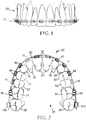
- Figure 1 illustrates an example of an upper dental arch 20 of an orthodontic patient that is undergoing orthodontic therapy.
- An orthodontic brace broadly designated by the numeral 22, is connected to the teeth of the upper dental arch 20.
- the brace 22 includes a set of appliances along with an archwire that is received in the appliances, as will be described in more detail below.
- Figure 2 is an enlarged view of the upper dental arch 20 along with the brace 22, looking in an upwardly direction toward the outer or occlusal tips of the teeth.
- the upper dental arch 22 includes a left quadrant and a right quadrant, each of which has a central incisor tooth 24, a lateral incisor tooth 26, a cuspid tooth 28, a first bicuspid tooth 30, and a second bicuspid tooth 32.
- each of the left and right quadrants includes a first molar tooth 34 and a second molar tooth 36.
- the illustration of the upper dental arch 22 shown in Figures 1 and 2 is only one example of dentition, and many variations are possible.
- the patient may lack one or more of the illustrated teeth, as may occur in adolescent patients when some of the permanent teeth have not yet erupted.
- one or more teeth may have been removed prior to orthodontic treatment in order to reduce crowding, especially in instances where the overall size of the dental arch is relatively small.
- the upper brace 22 includes a set of appliances that is connected to the teeth of the upper arch 20.
- the brace 22 in each of the left and right quadrants includes a central incisor appliance 38 that is coupled to the central incisor tooth 24, a lateral incisor appliance 40 that is connected to the lateral incisor tooth 26, and a cuspid appliance 42 that is connected to the cuspid tooth 28.
- the brace 22 also includes in each quadrant a first bicuspid appliance 44 that is coupled to the first bicuspid tooth 30, a second bicuspid appliance 46 that is connected to the second bicuspid tooth 32, a first molar appliance 48 that is connected to the first molar tooth 34 and a second molar appliance 100 that is connected to the second molar tooth 36.
- the brace 22 further includes an archwire 52 that is made of a resilient material. Suitable materials include, for example, metallic materials such as alloys of nitinol and stainless steel. In plan view, the archwire 52 has an overall, generally "U"-shaped configuration that extends along both of the quadrants.
- the molar appliance 100 is shown in more detail in Figures 3-9 .
- the appliance 100 has a base 102 with an outer, tooth-facing surface 104 for coupling to the outer enamel surface of a molar tooth. Consequently, the first side 104 of the base 102 in this embodiment can also be deemed a lingual surface and the second side 106 can be deemed a buccal surface.
- a body 130 extends outwardly from the base 102 in a generally buccal direction and includes an elongated archwire passage 150 extending across and through the body 130 in a generally mesial-distal direction.
- the appliance 100 of this embodiment and the orthodontic appliances of other embodiments, unless otherwise indicated, are described herein using a reference frame attached to a labial surface of a tooth on the upper or lower jaw. Consequently, terms such as labial, lingual, buccal, mesial, distal, occlusal, and gingival used to describe the appliance 100 are relative to the chosen reference frame.
- the embodiments, however, are not limited to the chosen reference frame and descriptive terms, as the appliance 100 may be used on other teeth and in other orientations within the oral cavity.
- the appliance 100 may also be coupled to the surface of an anterior tooth.
- the descriptive terms used herein may not directly apply when there is a change in reference frame.
- the embodiments are intended to be independent of location and orientation within the oral cavity and the relative terms used to describe embodiments of the orthodontic bracket are to merely provide a clear description of the embodiments in the drawings.
- the relative terms buccal, labial, lingual, mesial, distal, occlusal, and gingival are in no way limiting the embodiments to a particular location or orientation.
- the base 102 typically has a shape that matches or approximates the contour of the tooth surface for which the appliance 100 is intended.
- the base 102 has a concave, compound contour that is curved in directions adapted to mate with the convex shape of a molar tooth.
- the outer, lingual surface 104 may feature the compound contours disclosed herein, with the buccal surface 106 having a substantially different contour.
- the contour of the base 102 includes a first mesial-distal curve 108.
- the first mesial-distal curve 108 can be viewed in a reference plane parallel to the occlusal plane of the patient when the appliance 100 is mounted on a tooth, and is depicted in Figure 11 .
- the base 102 also includes an occlusal-gingival curve 109 that can be viewed in a reference plane perpendicular to the occlusal plane and is depicted in Figure 4 .
- the outer, lingual surface 104 may include mesh, holes, bumps, recesses, undercuts, a microetched surface, glass grit, bonded particles, an organo-silane treated surface, or any other known mechanical or chemical modification to enhance adhesive bonding between the base 102 and the underlying tooth.
- the base may include a fixed, compressible material to assist in filling gaps between the base 102 and the tooth structure. Suitable compressible materials are described in US Publication No. 2009/0233252 (Cinader ).
- the base 102 can advantageously include additional, compound curvature in the mesial-distal direction.
- the base 102 includes wings 112, 113 disposed adjacent the mesial and distal edges of the base 102, as well as a central portion 110 disposed between the mesial wing 112 and the distal wing 113.
- the wings 112, 113 are rotated relative to the central portion 110 in directions away from the buccal surface 106 of the base 102.
- each wing 112, 113 introduces an additional mesial-distal curve to the base 102 (particularly lingual surface 104 thereof), with wing 112 incorporating mesial-distal curve 114 and wing 113 incorporating mesial-distal curve 115.
- the additional mesial-distal curves 114, 115 include a different radius than the first mesial-distal curve 108 of the central portion 110, thereby creating compound curvature in the mesial-distal direction.
- the base may include one of a mesial or distal wing, and accordingly fewer compound curves.
- each of the second and third mesial-distal curves 114, 115 has a smaller radius of curvature than the radius of the first mesial-distal curve 108. This can allow, in certain circumstances, for tighter wrapping of the base 102 about the buccal curvature of the intended molar tooth surface for bonding.
- the second and third mesial-distal curves 114, 115 include the same radius of curvature, providing the base 102 with a symmetrical appearance.
- the second and third curves 114, 115 may each have a different radius of curvature, creating a base featuring at least three distinct mesial-distal curves.
- the first mesial-distal curve 108 has a radius of 17.15 mm (0.675 inches), with the second and third mesial-distal curves 114, 115 having a radius of 5.1 mm (0.2 inches).
- the second and third mesial-distal curves 114, 115 having a radius of 5.1 mm (0.2 inches).
- the wings 112, 113 are rotated relative to the central portion 110 along lines of compound curvature 116, 117 that are spaced from the center of the base and buccal indent 119.
- the lines of compound curvature 116, 117 extend across the base 102 in a generally occlusal-gingival direction. Either or both of the lines of compound curvature 116, 117 may be curved about an arc in embodiments of the base 102 featuring an occlusal-gingival curvature.
- the lines of compound curvature 116, 117 extend along a reference axes angularly offset from the occlusal-gingival lateral axes 121 of the base 102.
- the degree of angular offset may be selected to approximate the buccal contour of the first or second molar.
- the offset angle "A" is at least 5 degrees, in other embodiments at least 10 degrees, in other embodiments at least 15 degrees, and in other embodiments at least 20 degrees.
- the offset angle is no greater than 60 degrees, in some embodiments no greater than 50 degrees, in some embodiments no greater than 45 degrees, and in some embodiments no greater than 30 degrees. In presently preferred circumstances, the offset angle A is between 10 and 30 degrees.
- the lines of compound contour 116, 117 When extending at offset angle "A", the lines of compound contour 116, 117 give the central portion 110 a semi-trapezoidal appearance in directions along a buccal-lingual axis. In other embodiments, the lines of compound contour 116, 117 can extend substantially parallel to the lateral axis 121, such that offset angle A is between 0-5 degrees. The offset angle A may be the same or different between lines of compound curvature 116, 117.
- the lines of compound curvature 116, 117 are spaced from each other at the occlusal edge 120 and the gingival edge 122 of the base 102, such that portion of the mesial wing 112 underlies a portion of the body 130.
- the central portion 110 may, in some embodiments, include a buccal indent 119, which may be received at least partially within a mesiobuccal developmental groove when the appliance 100 is seated on a first molar. Unlike the typical size of wings 112, 113, the buccal indent 119 does not extend the full occlusal-gingival width of the base 102.
- the buccal indent 119 approximates the appearance of the buccal surface of the first molar near buccal cusps, enhancing a practitioner's ability to correctly position the appliance 100 relative to the tooth surface.
- the additional curvature provided by the mesial and distal wings 112, 113 provides for a reduced gap between the tooth facing surface 104 and the molar tooth enamel, as the compound, mesial-distal curvature more closely approximates the buccal surface contour of a molar tooth.
- the base may be curved along only one direction or alternatively have a flat configuration.
- the molar appliance 100 may be pre-adjusted for torque and angulation.
- Tooth angulation can be defined according to the teachings of Dr. Lawrence F. Andrews as the mesiodistal cant of the facial axis of the clinical crown ("FACC") relative to a line perpendicular to the occlusal plane (see, e.g., Straight Wire, The Concept and Appliance, by Lawrence F. Andrews, (L. A. Wells Co., (C)1989)).
- Bracket angulation may be defined as the particular angular orientation of the archwire slot of the bracket relative to the base of the bracket in order to provide tooth angulation.
- Tooth torque may be defined as the buccolabial-lingual cant of the FACC when measured from a line perpendicular to the occlusal plane. Consequently, bracket torque may be defined as the orientation of the archwire slot relative to the base of the bracket such that the desired tooth torque is attained. Bracket torque is typically provided via a specified angle of the archwire slot or passage, i.e., "torque in the slot", or an angle is formed in the tooth mounting surface of a bracket, i.e., "torque in the base”. Under either configuration, the appliance 100 can be provided with a certain torque that is designated by the letter "B" in Figure 9 .
- the torque, or angle B is equivalent to the angle between a reference plane 175 containing the lingual wall of an archwire passage 150 and a reference line 177.
- the reference line 177 extends in an occlusal-gingival direction and tangent to the base surface 104 at a point that is located in a lingual direction beneath the mesial-distal center and occlusal-gingival center of the archwire passage 150.
- Reference line 177 accordingly lies within a torque plane of the appliance 100.
- Table I sets out exemplary torque and angulation values for the appliances according to the present disclosure.
- any or all of the torque and/or angulation values in Table I may vary from the following values by plus or minus about 2 degrees, and more preferably by plus or minus about 1 degree.
- the body 130 includes an occlusal side 131, a buccal side 133 and a gingival side 135 that define the exterior.
- a lingual edge of the occlusal side 131 and a lingual edge of the gingival side 135 are integrally connected to the buccal surface 106 of the base 102.
- the gingival side 134 and occlusal side 131 may be reversed.
- the sides 131, 133, 135 together present a generally "U"-shaped configuration.
- the sides 131, 133, 135 present a semi-trapezoidal configuration.
- the body 130 may include curved or rounded exterior surfaces joining one or both of the occlusal side 131 and gingival side 135 to the buccal side 133 in order to reduce irritation of adjacent tissue (e.g., the patient's cheeks) in the oral cavity.
- the rounded exterior surfaces preferably extend substantially the entire mesial-distal length of the body 130, and can be a variety of radius sizes depending on the overall size of the body 130.
- the mesial and distal end regions of the sides 131, 133, 135 may also include curved surfaces in order to reduce irritation of adjacent tissue.
- the buccal side 133 includes a substantially planar surface 134, which can, in certain implementations of the present disclosure, reside in a reference plane ("P" in Figures 4 and 5 ) that is parallel to the torque plane of the appliance.
- P a reference plane
- a practitioner will typically provide pressure to a buccal surface of a molar appliance via a hand instrument during application of the molar appliance to a tooth surface. Depending on the orientation of the base and the appliance body, this pressure may create a moment of force about the central, longitudinal axis of the appliance, causing the appliance to tip or rotate relative to the tooth surface.
- Providing a buccal surface 134 that is parallel or substantially parallel to the torque plane helps to prevent or reduce undue rotation or tipping of the appliance 100; ensuring the bracket is seated in the prescribed or otherwise desired location.
- the occlusal side 131 may include one or more canted, planar surfaces 132 extending towards the buccal side 133 at an oblique angle relative to the buccal surface 106 of the base 102.
- the gingival side 135 may also include substantially planar surfaces 136 extending from the buccal surface 106 of the base 102.
- the substantially planar surfaces 136 are typically not parallel to the canted surfaces 132 of the occlusal side 131.
- the gingival planar surfaces 136 are substantially perpendicular to the torque plane of the bracket.
- the occlusal-gingival thickness of the mesial section 138 of the body 130 at the base 102 is greater than the occlusal-givingal thickness of the distal section 139, giving the body 130 a tapered appearance when viewed from the orientation in Figure 6 .
- the body 130 also includes a pair of opposing recesses 140, 144 that extend along a portion of the occlusal side 131 and the gingival side 135, respectively.
- Each recess 140, 144 can be configured so that one side thereof is open to one side of the body 130, and so that left and right sides 165 thereof are inclined at an angle "C" so as to have a trapezoidal cross section when viewed from the buccal direction (See Figure 6 ).
- the opposing recesses 140, 144 facilitate gripping of the appliance by a hand instrument such as fine-tipped pliers, tweezers or other tools used by the practitioner to grasp the body 130 during use.
- the occlusal recess 140 includes a recessed surface 141 that is located between canted surfaces 132.
- the recessed surface extends, at least in this embodiment, between the buccal surface 134 and the base 102 in an orientation that is not parallel to the canted surfaces 132.
- the gingival recesses 144 may also include a recessed surface 145.
- both of the recessed surfaces 141, 145 extend along a plane that is substantially perpendicular to the torque plane of appliance 100. Orienting either or both of the recessed surfaces 141, 145 at a substantially perpendicular orientation relative to the torque plane helps to prevent the tube from disengaging from a grasping hand instrument as the tube is pressed onto the tooth during bonding.
- recesses 140, 144 are provided with placement enhancement structure such as protrusions (including pins, posts, ridges and the like) or apertures (including pores or cavities).
- placement enhancement structure such as protrusions (including pins, posts, ridges and the like) or apertures (including pores or cavities).
- the placement enhancement structure may comprise a roughened surface, a knurled surface, or a surface that is provided with other types of patterns and/or cross-hatchings.
- the placement enhancement structure may comprise any combination of the foregoing.
- the placement enhancement structure further facilitates gripping of the appliance by a hand instrument such as fine-tipped pliers or other tools used by the practitioner to grasp the body 130 and helps ensure that the appliance 100 will not unduly shift relative to the hand instrument when the practitioner is maneuvering the appliance 100 in the oral cavity and placing the appliance 100 on the tooth surface. Additional options and aspects of the placement enhancement structure are described in US Patent No. 6,893,257 (Kelly ).
- the body 130 may include a positioning channel 148 in the buccal surface 134.
- the channel 148 can be used during a bonding procedure for shifting the appliance 100 to a precise location. For example, once the base 102 of the appliance 100 has been placed on the tooth via a bonding adhesive, the practitioner may elect to place the tip of a probe in the channel 148 and shift the appliance 10 slightly until a desired position is attained.
- an elongated archwire passage 150 extends across and through the body 130 in a generally mesial-distal direction.
- the archwire slot 150 includes a mesial section 156 and a distal section 159, with the distal section 159 generally extending a greater length of the passage 150 relative to the mesial section 156.
- the archwire slot is defined by an occlusal wall 151, a gingival wall 152, a buccolabial wall 153, as well as a tooth-facing or lingual wall 154.
- the mesial section 156 features tapered, convex portions 158 of the walls 151, 152, 153, 154 to present a funneled entry.
- the mesial section 156 includes at least two, in some embodiments at least three, and in the depicted embodiment four convex wall portions 158.
- the convex wall portions 158 provide a taper having at least one section of continuous curvature such that the interior of the passage 150 lacks or minimizes a deliberate demarcation between mesial section 156 and the distal section 159. In this way, the initial entrance to the archwire slot 150 is wider, allowing for easier threading of the archwire (not shown) through the archwire passage 150.
- any binding friction or potentially impeding stop surfaces between the archwire and the passage 150 are reduced, thereby facilitating prompt insertion of the archwire.
- the depicted mesial section 156 includes convex wall portions 158 providing a continuously curved taper between the mesial passage entrance 157 and the distal section 159 of the passage 150.
- one or more of the convex wall portions 158 may include a flat, planar land located between curved sections or at the mesial entrance.
- the convex wall portions 158 can include a compound curvature, much like the base 102. In such embodiments, a first radius of curvature at and adjacent the mesial entrance 157 is typically greater than a second radius of curvature more adjacent the distal section 159.
- the convex wall portion 158 may present a continuously curved taper or may include one or more flat land areas.
- the curved surface 158 of the gingival wall 152 typically includes the largest surface area and radius (or radii) of curvature.
- curved surface 158 includes different curvature at the buccal edge and the lingual edge of the gingival wall 152.
- the buccal edge of the gingival wall 152 can include a compound contour having a first radius near the mesial entrance 157 of 3.30 mm (0.13 inches) and a second radius adjacent the distal section 159 of 0.51 mm (0.02 inches).
- the lingual edge of the gingival wall 152 can include a compound contour having a first radius near the mesial entrance 157 of 10.2 mm (0.4 inches) and a second radius adjacent the distal section 159 of 0.76 mm (0.03 inches).
- the archwire passage 150 also includes a distal section 159 that has a generally rectangular configuration in cross-section as shown for example in Fig. 5 .
- the distal section 159 extends from the distal side of the mesial section 156 of the passage 150 to the distal end of the walls 151, 152, 153, and 154.
- the archwire passage 150 has a rectangular shape when viewed in a longitudinally transverse reference plane (See Fig. 5 ) although circular, square, ovular, and other suitable shapes are also possible. It should likewise be appreciated that the buccal tube of the present invention may be used for archwires having any useful cross-sectional dimensions.
- the lingual wall 154 is flat and extends in a reference plane that is parallel to the buccal labial wall 153.
- the gingival wall 152 extends in a reference plane that is parallel to the occlusal wall 151.
- no wall 151, 152, 153, 154 is parallel or substantially parallel to the gingival surface 135 or the buccal surface 133. This configuration of the archwire passage 150 ensures that no wall is parallel or substantially parallel to the torque plane of the appliance.
- the appliance 100 may optionally include a hook 160 for connection to another orthodontic device.
- suitable devices include coil springs and elastomeric force modules that are connected to other appliances in the patient's oral cavity.
- such devices have an end section with a hole or opening that receives at least a distal portion 162 of the hook, although other types of connections are also possible.
- the hook 160 in this embodiment has an overall curved configuration that extends from the gingival side 135 of the body 130.
- the curved longitudinal axis of the hook 160 extends away from the body 130 first in a gingival direction, and then in a distal direction.
- At least the gingivally extending hook portion 161 resides in and is coplanar with the plane P of the planar buccal surface portion 134.
- the coplanar relationship of the hook 160 and buccal surface 134 reduces the profile of the appliance 100 near the patient's adjacent gingival and cheek tissue, enhancing the relative comfort of the appliance 100 when installed.
- the gingivally extending portion 161 may project towards the base 102, further reducing the buccal-lingual profile of the appliance 100. All of the surfaces of the hook 160 can be smoothly rounded to avoid irritating soft tissue in the oral cavity.
- the appliance 100 as illustrated in the accompanying drawings is adapted to be adhesively connected directly to the surface of a molar tooth.
- the appliance 100 could be fixed to an orthodontic band that is adapted to encircle the patient's molar tooth.
- Suitable orthodontic bands include stainless steel bands, such as Victory Series brand bands and Unitek brand bands from 3M Unitek Corporation.
- the molar appliances according to the present disclosure maybe made of any material that is suitable for use in the oral cavity and has sufficient strength to resist the stresses normally encountered during the course of orthodontic treatment. Suitable materials include, for example, metallic materials (such as stainless steel), ceramic materials (such as monocrystalline or polycrystalline alumina), and plastic materials (such as fiber-reinforced polycarbonate).
- the appliance 100 is integrally made as a unitary component by a metal injection molding or additive manufacturing process.
- body 130 may be manufactured separately and then connected directly to the base 102 by weld or brazening operation.
- Components of the appliance 100 may be manufactured according to any number of methods known to the skilled artisan. These methods include, but are not limited to, milling, investment casting, metal injection molding, and additive manufacturing. If desired, one or more of the base 102, body 130, and auxiliary attachment can also be manufactured from other classes of materials, such as ceramics, polymers, or composites. If polymeric components are used, these may optionally be formed by milling, injection molding, extrusion or additive manufacturing. Examples of suitable additive manufacturing processes include solid freeform fabrication such as 3D printing processes, stereolithography methods, fused deposition modeling, laminated object manufacturing, laser engineered net shaping, selective laser sintering, shape deposition manufacturing, selective laser melting , and solid ground curing.
- An example of a suitable 3D printing machine is the Eden brand 500V printer from Objet Geometries Ltd., using FullCure 720 acrylic-based photopolymer printing material (also available from Objet Geometries Ltd.).
- the base 102 may be independently designed using CAD/CAM software.
- Digital data can be used to, for example, design and modify the base of the appliance to a shape that comprises an approximate contour of at least a portion of the target (i.e., intended bonding location) tooth surface.
- data could be gathered from a number of individuals regarding the buccal surface contour of the first and second molar teeth, including for example, the height of a tooth in an occlusal-gingival direction and the width of a tooth in a mesial-distal direction.
- a number of compound contours could be developed using statistical analysis in order to determine the optimal configuration of the outer surface 104 of the base 102.
- the outer surface 102 can be a negative replica of a patient's tooth prepared using digital data obtained with, for example, an intra-oral or extra-oral scan of the patient's dental arch or a model thereof.
- the appliance 100 as exemplified in the drawings is a molar or buccal tube appliance that is especially adapted for use with molar teeth.
- the principles of the present disclosure may be used with other orthodontic appliances as well.
- orthodontic brackets adapted for bonding to anterior, cuspid, bicuspid, and premolar teeth may also include a mesial wing bent about a line of compound curvature.
Landscapes
- Health & Medical Sciences (AREA)
- Oral & Maxillofacial Surgery (AREA)
- Dentistry (AREA)
- Epidemiology (AREA)
- Life Sciences & Earth Sciences (AREA)
- Animal Behavior & Ethology (AREA)
- General Health & Medical Sciences (AREA)
- Public Health (AREA)
- Veterinary Medicine (AREA)
- Dental Tools And Instruments Or Auxiliary Dental Instruments (AREA)
Description
- Orthodontic therapy is a specialized area of dentistry concerning the supervised treatment of malpositioned (or crooked) teeth. Generally such treatment involves the judicious application of light continuous forces to the teeth using one or more orthodontic appliances. These forces stimulate changes in surrounding bone structure, thereby gradually directing teeth to their proper locations in the oral cavity. Orthodontic therapy can provide many benefits, including ease of maintaining hygiene, improved facial appearance, as well as improved bite function. Treatment often lasts between two and three years, depending on the complexity of the case.
- Fixed appliances, or "braces," represent one type of orthodontic treatment in which tiny slotted appliances, called brackets, are attached to the teeth. A resilient, U-shaped archwire is then placed into the slots of the brackets. When ligated to the brackets, the archwire acts as a track that guides teeth toward their proper locations during the course of treatment. In the beginning of treatment, the archwire tends to have small cross-sectional dimensions to facilitate ligation and also keep forces imparted to the teeth relatively low as the teeth unravel. In later stages of treatment, the teeth approach their target positions, allowing for progressively larger (and stiffer) wires to be used to improve the practitioner's control over the associated teeth.
- The ends of the archwire are generally captured in tube-shaped molar appliances commonly called buccal tubes, which are affixed to the patient's molar teeth. Buccal tubes typically feature an enclosed passage extending in a mesial-distal direction. The enclosed passage helps prevent the end of the archwire from contacting the patient's soft tissue in the oral cavity, which might otherwise lead to pain and injury. In some instances, buccal tubes are provided with a convertible cap along one side of the passage that can be opened in order to convert the tube into a bracket when desired.
- While the archwire is initially distorted when ligated to the brackets, it gradually returns toward its original shape, functioning as a track that guides movement of teeth toward desired positions. The brackets, tubes, and archwire are collectively known as "braces."
-
US 2013/0309625 discloses an orthodontic bracket having three archwire retention channels in the mesial-distal directions, a central channel and two side channels. The two side channels each include a pair of spaced apart inverted archwire retaining regions having a recess that opens generally towards the bracket base. Each such recess is for grasping or holding an archwire thereinUS 5,556,277 A1 discloses a flared buccal tube having an internally tapered mesial section. - Issues related to conventional buccal tubes and molar appliances include: an insufficient fit between the bonding base and the molar tooth surface; an enhanced difficulty of threading an archwire (particularly a larger wire at the conclusion of treatment) through an enclosed archwire passage; and a tendency of the appliance to tip or rotate as pressure is applied during bonding.
- The present disclosure provides molar appliances particularly designed to address the issues outlined above, giving a treating practitioner greater confidence in the installation and orientation of the molar appliances during treatment. The molar appliances of the present disclosure feature a tooth bonding base including compound curvature in the mesial-distal direction, providing for a closer fit relative to the buccal surface contour. The appliances feature a funneled entry to the archwire passage that includes a plurality of surfaces with convex curvature. The curved surfaces guide the end of archwire into the slot, while minimizing or avoiding abrupt transition areas that can impede insertion. Moreover, the appliances of the present disclosure can include a buccal surface on the appliance body that is substantially parallel to the torque plane. Aligning the buccal surface to the torque plane reduces the chance of rotation on application of pressure used to bond the appliance to the molar tooth surface.
- In one aspect, the present disclosure provides an orthodontic appliance according to claim 1.
- The terms "comprises" and variations thereof do not have a limiting meaning where these terms appear in the description and claims. Such terms will be understood to imply the inclusion of a stated step or element or group of steps or elements but not the exclusion of any other step or element or group of steps or elements. By "consisting of' is meant including, and limited to, whatever follows the phrase "consisting of." Thus, the phrase "consisting of' indicates that the listed elements are required or mandatory, and that no other elements may be present. By "consisting essentially of" is meant including any elements listed after the phrase, and limited to other elements that do not interfere with or contribute to the activity or action specified in the disclosure for the listed elements. Thus, the phrase "consisting essentially of" indicates that the listed elements are required or mandatory, but that other elements are optional and may or may not be present depending upon whether or not they materially affect the activity or action of the listed elements.
- The words "preferred" and "preferably" refer to embodiments of the disclosure that may afford certain benefits, under certain circumstances. However, other embodiments may also be preferred, under the same or other circumstances. Furthermore, the recitation of one or more preferred embodiments does not imply that other embodiments are not useful, and is not intended to exclude other embodiments from the scope of the disclosure.
- In this application, terms such as "a", "an", and "the" are not intended to refer to only a singular entity, but include the general class of which a specific example may be used for illustration. The terms "a", "an", and "the" are used interchangeably with the term "at least one." The phrases "at least one of' and "comprises at least one of' followed by a list refers to any one of the items in the list and any combination of two or more items in the list.
- As used herein, the term "or" is generally employed in its usual sense including "and/or" unless the content clearly dictates otherwise.
The term "and/or" means one or all of the listed elements or a combination of any two or more of the listed elements. - Also herein, all numbers are assumed to be modified by the term "about" and preferably by the term "exactly." As used herein in connection with a measured quantity, the term "about" refers to that variation in the measured quantity as would be expected by the skilled artisan making the measurement and exercising a level of care commensurate with the objective of the measurement and the precision of the measuring equipment used.
Also herein, the recitations of numerical ranges by endpoints include all numbers subsumed within that range as well as the endpoints (e.g., 1 to 5 includes 1, 1.5, 2, 2.75, 3, 3.80, 4, 5, etc.). - As used herein as a modifier to a property or attribute, the term "generally", unless otherwise specifically defined, means that the property or attribute would be readily recognizable by a person of ordinary skill but without requiring absolute precision or a perfect match (e.g., within +/- 20 % for quantifiable properties). The term "substantially", unless otherwise specifically defined, means to a high degree of approximation (e.g., within +/- 10% for quantifiable properties) but again without requiring absolute precision or a perfect match. Terms such as same, equal, uniform, constant, strictly, and the like, are understood to be within the usual tolerances or measuring error applicable to the particular circumstance rather than requiring absolute precision or a perfect match.
- The above summary of the present disclosure is not intended to describe each disclosed embodiment or every implementation of the present disclosure. The description that follows more particularly exemplifies illustrative embodiments. In several places throughout the application, guidance is provided through lists of examples, which examples can be used in various combinations. In each instance, the recited list serves only as a representative group and should not be interpreted as an exclusive list.
-
-
Fig. 1 is a front elevational view showing the upper teeth of an exemplary patient undergoing orthodontic treatment, wherein orthodontic appliances are fixed to the teeth and an archwire has been connected to the appliances; -
Fig. 2 is a bottom or occlusal view of the teeth, appliances and archwire illustrated inFig. 1 ; -
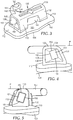
Fig. 3 is an enlarged perspective view of one of the appliances that is connected to at least one of the molar teeth shown inFigs. 1 and 2 , looking at the appliance in a direction toward its mesial, buccal and occlusal sides; -
Fig. 4 is an end elevational view of the appliance shown inFig. 3 , looking at the appliance toward its mesial side; -
Fig. 5 is an end elevational view of the appliance shown inFigs. 3 and 4 , looking at the appliance toward its distal side; -
Fig. 6 is a front elevational view of the appliance shown inFigs. 3-6 , looking at the appliance toward its buccal side; -
Fig. 7 is a top view of the appliance shown inFigs. 3-7 , looking at the appliance toward its gingival side; -
Fig. 8 is a cross-sectional view taken across lines 8-8 ofFig. 6 ; -
Fig. 9 is a cross-sectional view taken across lines 9-9 ofFig. 6 ; -
Fig. 10 is a front elevational view of the base of the appliance ofFigures 3-9 , looking at the base toward its buccal side; -
Fig. 11 is a bottom view of the base ofFigure 10 , looking at its gingival side; and -
Fig. 12 is a top view of the base ofFigures 10-11 , looking at its occlusal side. - While the above-identified figures set forth several embodiments of the disclosure other embodiments are also contemplated, as noted in the description. In all cases, this disclosure presents the invention by way of representation and not limitation. It should be understood that numerous other modifications and embodiments can be devised by those skilled in the art, which fall within the scope of the invention.
-
- "Mesial" means in a direction toward the center of the patient's curved dental arch. "Distal" means in a direction away from the center of the patient's curved dental arch.
- "Occlusal" means in a direction toward the outer tips of the patient's teeth.
- "Gingival" means in a direction toward the patient's gums or gingiva.
- "Buccal" means in a direction toward the patient's cheeks.
- "Labial" means in a direction toward the patient's lips.
- "Lingual" means in a direction toward the patient's tongue.
-
Figure 1 illustrates an example of an upperdental arch 20 of an orthodontic patient that is undergoing orthodontic therapy. An orthodontic brace, broadly designated by the numeral 22, is connected to the teeth of the upperdental arch 20. Thebrace 22 includes a set of appliances along with an archwire that is received in the appliances, as will be described in more detail below. -
Figure 2 is an enlarged view of the upperdental arch 20 along with thebrace 22, looking in an upwardly direction toward the outer or occlusal tips of the teeth. The upperdental arch 22 includes a left quadrant and a right quadrant, each of which has acentral incisor tooth 24, alateral incisor tooth 26, acuspid tooth 28, a firstbicuspid tooth 30, and a secondbicuspid tooth 32. In addition, each of the left and right quadrants includes afirst molar tooth 34 and asecond molar tooth 36. - The illustration of the upper
dental arch 22 shown inFigures 1 and 2 is only one example of dentition, and many variations are possible. For example, the patient may lack one or more of the illustrated teeth, as may occur in adolescent patients when some of the permanent teeth have not yet erupted. Alternatively, one or more teeth may have been removed prior to orthodontic treatment in order to reduce crowding, especially in instances where the overall size of the dental arch is relatively small. - The
upper brace 22 includes a set of appliances that is connected to the teeth of theupper arch 20. In particular, thebrace 22 in each of the left and right quadrants includes acentral incisor appliance 38 that is coupled to thecentral incisor tooth 24, alateral incisor appliance 40 that is connected to thelateral incisor tooth 26, and acuspid appliance 42 that is connected to thecuspid tooth 28. Thebrace 22 also includes in each quadrant a firstbicuspid appliance 44 that is coupled to the firstbicuspid tooth 30, a secondbicuspid appliance 46 that is connected to the secondbicuspid tooth 32, afirst molar appliance 48 that is connected to thefirst molar tooth 34 and asecond molar appliance 100 that is connected to thesecond molar tooth 36. - The
brace 22 further includes anarchwire 52 that is made of a resilient material. Suitable materials include, for example, metallic materials such as alloys of nitinol and stainless steel. In plan view, thearchwire 52 has an overall, generally "U"-shaped configuration that extends along both of the quadrants. - The
molar appliance 100 is shown in more detail inFigures 3-9 . Theappliance 100 has a base 102 with an outer, tooth-facingsurface 104 for coupling to the outer enamel surface of a molar tooth. Consequently, thefirst side 104 of the base 102 in this embodiment can also be deemed a lingual surface and thesecond side 106 can be deemed a buccal surface. Abody 130 extends outwardly from the base 102 in a generally buccal direction and includes anelongated archwire passage 150 extending across and through thebody 130 in a generally mesial-distal direction. - The
appliance 100 of this embodiment and the orthodontic appliances of other embodiments, unless otherwise indicated, are described herein using a reference frame attached to a labial surface of a tooth on the upper or lower jaw. Consequently, terms such as labial, lingual, buccal, mesial, distal, occlusal, and gingival used to describe theappliance 100 are relative to the chosen reference frame. The embodiments, however, are not limited to the chosen reference frame and descriptive terms, as theappliance 100 may be used on other teeth and in other orientations within the oral cavity. For example, theappliance 100 may also be coupled to the surface of an anterior tooth. Those of ordinary skill in the art will recognize that the descriptive terms used herein may not directly apply when there is a change in reference frame. Nevertheless, the embodiments are intended to be independent of location and orientation within the oral cavity and the relative terms used to describe embodiments of the orthodontic bracket are to merely provide a clear description of the embodiments in the drawings. As such, the relative terms buccal, labial, lingual, mesial, distal, occlusal, and gingival are in no way limiting the embodiments to a particular location or orientation. - The base 102 typically has a shape that matches or approximates the contour of the tooth surface for which the
appliance 100 is intended. In the exemplary embodiment shown in the Figures, thebase 102 has a concave, compound contour that is curved in directions adapted to mate with the convex shape of a molar tooth. In other embodiments, the outer,lingual surface 104 may feature the compound contours disclosed herein, with thebuccal surface 106 having a substantially different contour. The contour of thebase 102 includes a first mesial-distal curve 108. The first mesial-distal curve 108 can be viewed in a reference plane parallel to the occlusal plane of the patient when theappliance 100 is mounted on a tooth, and is depicted inFigure 11 . The base 102 also includes an occlusal-gingival curve 109 that can be viewed in a reference plane perpendicular to the occlusal plane and is depicted inFigure 4 . - The outer,
lingual surface 104 may include mesh, holes, bumps, recesses, undercuts, a microetched surface, glass grit, bonded particles, an organo-silane treated surface, or any other known mechanical or chemical modification to enhance adhesive bonding between the base 102 and the underlying tooth. In other implementations, the base may include a fixed, compressible material to assist in filling gaps between the base 102 and the tooth structure. Suitable compressible materials are described inUS Publication No. 2009/0233252 (Cinader ). - The base 102 can advantageously include additional, compound curvature in the mesial-distal direction. As best illustrated in
Figures 10-12 , thebase 102 includeswings base 102, as well as acentral portion 110 disposed between themesial wing 112 and thedistal wing 113. Thewings central portion 110 in directions away from thebuccal surface 106 of thebase 102. Accordingly, eachwing lingual surface 104 thereof), withwing 112 incorporating mesial-distal curve 114 andwing 113 incorporating mesial-distal curve 115. The additional mesial-distal curves distal curve 108 of thecentral portion 110, thereby creating compound curvature in the mesial-distal direction. In alternative embodiments, the base may include one of a mesial or distal wing, and accordingly fewer compound curves. - For the base 102 depicted in
Figures 10-12 , each of the second and third mesial-distal curves distal curve 108. This can allow, in certain circumstances, for tighter wrapping of the base 102 about the buccal curvature of the intended molar tooth surface for bonding. In the depicted embodiment, the second and third mesial-distal curves third curves distal curve 108 has a radius of 17.15 mm (0.675 inches), with the second and third mesial-distal curves - Referring now to
Figure 10 , thewings central portion 110 along lines ofcompound curvature buccal indent 119. The lines ofcompound curvature compound curvature compound curvature base 102. The degree of angular offset may be selected to approximate the buccal contour of the first or second molar. In certain embodiments, the offset angle "A" is at least 5 degrees, in other embodiments at least 10 degrees, in other embodiments at least 15 degrees, and in other embodiments at least 20 degrees. In certain embodiments, the offset angle is no greater than 60 degrees, in some embodiments no greater than 50 degrees, in some embodiments no greater than 45 degrees, and in some embodiments no greater than 30 degrees. In presently preferred circumstances, the offset angle A is between 10 and 30 degrees. - When extending at offset angle "A", the lines of
compound contour compound contour lateral axis 121, such that offset angle A is between 0-5 degrees. The offset angle A may be the same or different between lines ofcompound curvature - The lines of
compound curvature occlusal edge 120 and thegingival edge 122 of thebase 102, such that portion of themesial wing 112 underlies a portion of thebody 130. Thecentral portion 110 may, in some embodiments, include abuccal indent 119, which may be received at least partially within a mesiobuccal developmental groove when theappliance 100 is seated on a first molar. Unlike the typical size ofwings buccal indent 119 does not extend the full occlusal-gingival width of thebase 102. Thebuccal indent 119 approximates the appearance of the buccal surface of the first molar near buccal cusps, enhancing a practitioner's ability to correctly position theappliance 100 relative to the tooth surface. - The additional curvature provided by the mesial and
distal wings tooth facing surface 104 and the molar tooth enamel, as the compound, mesial-distal curvature more closely approximates the buccal surface contour of a molar tooth. However, in certain instances (such as in appliances intended for anterior teeth), the base may be curved along only one direction or alternatively have a flat configuration. - The
molar appliance 100 may be pre-adjusted for torque and angulation. Tooth angulation can be defined according to the teachings of Dr. Lawrence F. Andrews as the mesiodistal cant of the facial axis of the clinical crown ("FACC") relative to a line perpendicular to the occlusal plane (see, e.g., Straight Wire, The Concept and Appliance, by Lawrence F. Andrews, (L. A. Wells Co., (C)1989)). Bracket angulation may be defined as the particular angular orientation of the archwire slot of the bracket relative to the base of the bracket in order to provide tooth angulation. Tooth torque may be defined as the buccolabial-lingual cant of the FACC when measured from a line perpendicular to the occlusal plane. Consequently, bracket torque may be defined as the orientation of the archwire slot relative to the base of the bracket such that the desired tooth torque is attained. Bracket torque is typically provided via a specified angle of the archwire slot or passage, i.e., "torque in the slot", or an angle is formed in the tooth mounting surface of a bracket, i.e., "torque in the base". Under either configuration, theappliance 100 can be provided with a certain torque that is designated by the letter "B" inFigure 9 . The torque, or angle B, is equivalent to the angle between areference plane 175 containing the lingual wall of anarchwire passage 150 and areference line 177. Thereference line 177 extends in an occlusal-gingival direction and tangent to thebase surface 104 at a point that is located in a lingual direction beneath the mesial-distal center and occlusal-gingival center of thearchwire passage 150.Reference line 177 accordingly lies within a torque plane of theappliance 100. - Table I sets out exemplary torque and angulation values for the appliances according to the present disclosure. Optionally, any or all of the torque and/or angulation values in Table I may vary from the following values by plus or minus about 2 degrees, and more preferably by plus or minus about 1 degree.
TABLE I Appliance Type Torque Angulation Central Incisor 17 4 Lateral Incisor 10 8 Cuspid -7 8 First Bicuspid -7 0 Second Bicuspid -7 0 First Molar -20 0 - Turning again to the
body 130 depicted inFigures 3-9 , thebody 130 includes anocclusal side 131, abuccal side 133 and agingival side 135 that define the exterior. A lingual edge of theocclusal side 131 and a lingual edge of thegingival side 135 are integrally connected to thebuccal surface 106 of thebase 102. Of course, depending upon the orientation of theappliance 100 in the patient's mouth, thegingival side 134 andocclusal side 131 may be reversed. - In end view, and as shown in
Figs. 4 and 5 , thesides buccal surface 106 of thebase 102, thesides body 130 may include curved or rounded exterior surfaces joining one or both of theocclusal side 131 andgingival side 135 to thebuccal side 133 in order to reduce irritation of adjacent tissue (e.g., the patient's cheeks) in the oral cavity. The rounded exterior surfaces preferably extend substantially the entire mesial-distal length of thebody 130, and can be a variety of radius sizes depending on the overall size of thebody 130. The mesial and distal end regions of thesides - The
buccal side 133 includes a substantiallyplanar surface 134, which can, in certain implementations of the present disclosure, reside in a reference plane ("P" inFigures 4 and 5 ) that is parallel to the torque plane of the appliance. A practitioner will typically provide pressure to a buccal surface of a molar appliance via a hand instrument during application of the molar appliance to a tooth surface. Depending on the orientation of the base and the appliance body, this pressure may create a moment of force about the central, longitudinal axis of the appliance, causing the appliance to tip or rotate relative to the tooth surface. Providing abuccal surface 134 that is parallel or substantially parallel to the torque plane helps to prevent or reduce undue rotation or tipping of theappliance 100; ensuring the bracket is seated in the prescribed or otherwise desired location. - The
occlusal side 131 may include one or more canted,planar surfaces 132 extending towards thebuccal side 133 at an oblique angle relative to thebuccal surface 106 of thebase 102. Thegingival side 135 may also include substantially planar surfaces 136 extending from thebuccal surface 106 of thebase 102. The substantially planar surfaces 136 are typically not parallel to the cantedsurfaces 132 of theocclusal side 131. In some embodiments, the gingival planar surfaces 136 are substantially perpendicular to the torque plane of the bracket. - The occlusal-gingival thickness of the
mesial section 138 of thebody 130 at thebase 102 is greater than the occlusal-givingal thickness of thedistal section 139, giving the body 130 a tapered appearance when viewed from the orientation inFigure 6 . - In the depicted implementations, the
body 130 also includes a pair of opposingrecesses occlusal side 131 and thegingival side 135, respectively. Eachrecess body 130, and so that left andright sides 165 thereof are inclined at an angle "C" so as to have a trapezoidal cross section when viewed from the buccal direction (SeeFigure 6 ). The opposing recesses 140, 144 facilitate gripping of the appliance by a hand instrument such as fine-tipped pliers, tweezers or other tools used by the practitioner to grasp thebody 130 during use. Theocclusal recess 140 includes a recessedsurface 141 that is located betweencanted surfaces 132. The recessed surface extends, at least in this embodiment, between thebuccal surface 134 and the base 102 in an orientation that is not parallel to the canted surfaces 132. The gingival recesses 144 may also include a recessedsurface 145. In the depicted embodiment, both of the recessedsurfaces appliance 100. Orienting either or both of the recessedsurfaces - Optionally, one or both of
recesses - The placement enhancement structure further facilitates gripping of the appliance by a hand instrument such as fine-tipped pliers or other tools used by the practitioner to grasp the
body 130 and helps ensure that theappliance 100 will not unduly shift relative to the hand instrument when the practitioner is maneuvering theappliance 100 in the oral cavity and placing theappliance 100 on the tooth surface. Additional options and aspects of the placement enhancement structure are described inUS Patent No. 6,893,257 (Kelly ). - As an additional option, the
body 130 may include apositioning channel 148 in thebuccal surface 134. Thechannel 148 can be used during a bonding procedure for shifting theappliance 100 to a precise location. For example, once thebase 102 of theappliance 100 has been placed on the tooth via a bonding adhesive, the practitioner may elect to place the tip of a probe in thechannel 148 and shift the appliance 10 slightly until a desired position is attained. - Referring now to
Figures 4-6 , anelongated archwire passage 150 extends across and through thebody 130 in a generally mesial-distal direction. Thearchwire slot 150 includes amesial section 156 and adistal section 159, with thedistal section 159 generally extending a greater length of thepassage 150 relative to themesial section 156. The archwire slot is defined by anocclusal wall 151, agingival wall 152, abuccolabial wall 153, as well as a tooth-facing orlingual wall 154. - The
mesial section 156 features tapered,convex portions 158 of thewalls mesial section 156 includes at least two, in some embodiments at least three, and in the depicted embodiment fourconvex wall portions 158. As can be appreciated by reference to the cross-section depicted inFigure 8 , theconvex wall portions 158 provide a taper having at least one section of continuous curvature such that the interior of thepassage 150 lacks or minimizes a deliberate demarcation betweenmesial section 156 and thedistal section 159. In this way, the initial entrance to thearchwire slot 150 is wider, allowing for easier threading of the archwire (not shown) through thearchwire passage 150. By eliminating or minimizing the transition between mesial and distal wall sections of the slot, any binding friction or potentially impeding stop surfaces between the archwire and thepassage 150 are reduced, thereby facilitating prompt insertion of the archwire. - The depicted
mesial section 156 includesconvex wall portions 158 providing a continuously curved taper between themesial passage entrance 157 and thedistal section 159 of thepassage 150. In other alternative implementations, one or more of theconvex wall portions 158 may include a flat, planar land located between curved sections or at the mesial entrance. In other embodiments, theconvex wall portions 158 can include a compound curvature, much like thebase 102. In such embodiments, a first radius of curvature at and adjacent themesial entrance 157 is typically greater than a second radius of curvature more adjacent thedistal section 159. In implementations with compound curvature, theconvex wall portion 158 may present a continuously curved taper or may include one or more flat land areas. - The
curved surface 158 of thegingival wall 152 typically includes the largest surface area and radius (or radii) of curvature. In one exemplary implementation,curved surface 158 includes different curvature at the buccal edge and the lingual edge of thegingival wall 152. For example, the buccal edge of thegingival wall 152 can include a compound contour having a first radius near themesial entrance 157 of 3.30 mm (0.13 inches) and a second radius adjacent thedistal section 159 of 0.51 mm (0.02 inches). The lingual edge of thegingival wall 152 can include a compound contour having a first radius near themesial entrance 157 of 10.2 mm (0.4 inches) and a second radius adjacent thedistal section 159 of 0.76 mm (0.03 inches). Those skilled in the art will appreciate that other dimensions and relationships between the convex wall portions are possible and can be tailored to a desired mesial-distal length and buccal height of thepassage 150. - The
archwire passage 150 also includes adistal section 159 that has a generally rectangular configuration in cross-section as shown for example inFig. 5 . Thedistal section 159 extends from the distal side of themesial section 156 of thepassage 150 to the distal end of thewalls archwire passage 150 has a rectangular shape when viewed in a longitudinally transverse reference plane (SeeFig. 5 ) although circular, square, ovular, and other suitable shapes are also possible. It should likewise be appreciated that the buccal tube of the present invention may be used for archwires having any useful cross-sectional dimensions. In thedistal section 159, thelingual wall 154 is flat and extends in a reference plane that is parallel to the buccallabial wall 153. Similarly, thegingival wall 152 extends in a reference plane that is parallel to theocclusal wall 151. In the depicted embodiment, nowall gingival surface 135 or thebuccal surface 133. This configuration of thearchwire passage 150 ensures that no wall is parallel or substantially parallel to the torque plane of the appliance. - The
appliance 100 may optionally include ahook 160 for connection to another orthodontic device. Examples of suitable devices include coil springs and elastomeric force modules that are connected to other appliances in the patient's oral cavity. Optionally, such devices have an end section with a hole or opening that receives at least adistal portion 162 of the hook, although other types of connections are also possible. Thehook 160 in this embodiment has an overall curved configuration that extends from thegingival side 135 of thebody 130. The curved longitudinal axis of thehook 160 extends away from thebody 130 first in a gingival direction, and then in a distal direction. At least the gingivally extendinghook portion 161 resides in and is coplanar with the plane P of the planarbuccal surface portion 134. The coplanar relationship of thehook 160 andbuccal surface 134 reduces the profile of theappliance 100 near the patient's adjacent gingival and cheek tissue, enhancing the relative comfort of theappliance 100 when installed. In other embodiments (not shown), thegingivally extending portion 161 may project towards thebase 102, further reducing the buccal-lingual profile of theappliance 100. All of the surfaces of thehook 160 can be smoothly rounded to avoid irritating soft tissue in the oral cavity. - The
appliance 100 as illustrated in the accompanying drawings is adapted to be adhesively connected directly to the surface of a molar tooth. However, other options for coupling the appliance 10 to the surface of the tooth are also contemplated. For example, theappliance 100 could be fixed to an orthodontic band that is adapted to encircle the patient's molar tooth. Suitable orthodontic bands include stainless steel bands, such as Victory Series brand bands and Unitek brand bands from 3M Unitek Corporation. - The molar appliances according to the present disclosure, including the appliances described in detail above, maybe made of any material that is suitable for use in the oral cavity and has sufficient strength to resist the stresses normally encountered during the course of orthodontic treatment. Suitable materials include, for example, metallic materials (such as stainless steel), ceramic materials (such as monocrystalline or polycrystalline alumina), and plastic materials (such as fiber-reinforced polycarbonate). In certain presently preferred circumstances, the
appliance 100 is integrally made as a unitary component by a metal injection molding or additive manufacturing process. As an alternative, however, body 130 (with or without auxiliaries) may be manufactured separately and then connected directly to thebase 102 by weld or brazening operation. - Components of the
appliance 100 may be manufactured according to any number of methods known to the skilled artisan. These methods include, but are not limited to, milling, investment casting, metal injection molding, and additive manufacturing. If desired, one or more of thebase 102,body 130, and auxiliary attachment can also be manufactured from other classes of materials, such as ceramics, polymers, or composites. If polymeric components are used, these may optionally be formed by milling, injection molding, extrusion or additive manufacturing. Examples of suitable additive manufacturing processes include solid freeform fabrication such as 3D printing processes, stereolithography methods, fused deposition modeling, laminated object manufacturing, laser engineered net shaping, selective laser sintering, shape deposition manufacturing, selective laser melting , and solid ground curing.. An example of a suitable 3D printing machine is the Eden brand 500V printer from Objet Geometries Ltd., using FullCure 720 acrylic-based photopolymer printing material (also available from Objet Geometries Ltd.). - In some embodiments, the
base 102 may be independently designed using CAD/CAM software. Digital data can be used to, for example, design and modify the base of the appliance to a shape that comprises an approximate contour of at least a portion of the target (i.e., intended bonding location) tooth surface. For example, data could be gathered from a number of individuals regarding the buccal surface contour of the first and second molar teeth, including for example, the height of a tooth in an occlusal-gingival direction and the width of a tooth in a mesial-distal direction. Next, a number of compound contours could be developed using statistical analysis in order to determine the optimal configuration of theouter surface 104 of thebase 102. Alternatively, theouter surface 102 can be a negative replica of a patient's tooth prepared using digital data obtained with, for example, an intra-oral or extra-oral scan of the patient's dental arch or a model thereof. - The
appliance 100 as exemplified in the drawings is a molar or buccal tube appliance that is especially adapted for use with molar teeth. However, the principles of the present disclosure may be used with other orthodontic appliances as well. For example, orthodontic brackets adapted for bonding to anterior, cuspid, bicuspid, and premolar teeth may also include a mesial wing bent about a line of compound curvature. - Various modifications and alterations to this invention will become apparent to those skilled in the art without departing from the scope of this invention. It should be understood that this invention is not intended to be unduly limited by the illustrative embodiments and examples set forth herein and that such examples and embodiments are presented by way of example only with the scope of the invention intended to be limited only by the claims set forth herein as follows.
Claims (7)
- An orthodontic appliance (100) comprising:a base (102) having a tooth facing surface (104) for bonding to tooth structure,a body (130) having a mesial section (138) and a distal section (139), the body (130) extending outwardly from the base (102), the body (130) including a facial wall (153), a lingual wall (154), an occlusal wall (151) and a gingival wall (152), the walls defining a passage (150) extending in a mesial-distal direction for receipt of a wire, the passage (150) including a mesial section (156) and a distal section (159),wherein the mesial section (156) includes an entrance (157) and wherein the occlusal-gingival thickness of the mesial section (138) of the body (130) at the base (102) is greater than the occlusal-gingival thickness of the distal section (139) of the body (130) at the base (102), characterized in that the mesial section (156) includes at least two convex wall portions (158) tapering from the entrance (157) towards the distal section (159), wherein the convex wall portions (158) include a section having a continuous curvature.
- The orthodontic appliance (100) of claim 1, wherein the mesial section (156) includes three convex wall portions (158).
- The orthodontic appliance (100) of claim 2, wherein the occlusal wall (151), gingival wall (152), and facial wall (153) each include a convex wall portion (158).
- The orthodontic appliance (100) of claim 3, and further comprising a convex wall portion (158) on the lingual wall (154).
- The orthodontic appliance (100) of claim 1, wherein the base (102) includes a central portion (110) underlying the body (130) and a least one wing (112, 113) spaced in a mesial or distal direction from the central portion (110) and rotated relative to the central portion (110), wherein the central portion (110) includes a first radius of curvature and the wing (112, 113) includes a second radius of curvature different from the first radius such that the base (102) exhibits a compound, mesial, distal curvature when viewed along a generally occlusal-gingival axis.
- The orthodontic appliance (100) of claim 5, and including a mesial wing (112) and a distal wing (113), wherein the mesial wing (112) and the distal wing (113) each include the second radius of curvature.
- The orthodontic appliance (100) of claim 5, wherein the wing (112, 113) is rotated relative to the central portion (110) at a line of compound curvature (116, 117), wherein the line (116, 117) extends across the base (102) in a generally occlusal-gingival direction, and wherein the base (102) includes a mesial-distal length and an occlusal-gingival width, and wherein the line of compound curvature (116, 117) extends across the entire occlusal-gingival width of the base (102).
Applications Claiming Priority (2)
| Application Number | Priority Date | Filing Date | Title |
|---|---|---|---|
| US201462020260P | 2014-07-02 | 2014-07-02 | |
| PCT/US2015/038353 WO2016003921A1 (en) | 2014-07-02 | 2015-06-29 | Molar appliance for an orthodontic brace |
Publications (3)
| Publication Number | Publication Date |
|---|---|
| EP3164096A1 EP3164096A1 (en) | 2017-05-10 |
| EP3164096A4 EP3164096A4 (en) | 2018-07-18 |
| EP3164096B1 true EP3164096B1 (en) | 2019-11-06 |
Family
ID=55019884
Family Applications (1)
| Application Number | Title | Priority Date | Filing Date |
|---|---|---|---|
| EP15814848.6A Active EP3164096B1 (en) | 2014-07-02 | 2015-06-29 | Molar appliance for an orthodontic brace |
Country Status (6)
| Country | Link |
|---|---|
| US (1) | US20180193111A1 (en) |
| EP (1) | EP3164096B1 (en) |
| JP (1) | JP2017524431A (en) |
| CN (1) | CN106659547B (en) |
| BR (1) | BR112017000025A2 (en) |
| WO (1) | WO2016003921A1 (en) |
Families Citing this family (5)
| Publication number | Priority date | Publication date | Assignee | Title |
|---|---|---|---|---|
| US11452579B2 (en) * | 2017-07-03 | 2022-09-27 | Clearcorrect Operating, Llc | Systems and methods for designing, and improving retention of, orthodontic aligners |
| CN112512458B (en) * | 2018-05-14 | 2023-06-06 | 埃尔斯盖恩产品私人有限公司 | Orthodontic anchor assembly |
| CN109330721A (en) * | 2018-10-12 | 2019-02-15 | 广州欧欧医疗科技有限责任公司 | Flap-cover buccal tube |
| CN109620433A (en) * | 2018-12-27 | 2019-04-16 | 四川大学 | A kind of orthotic device cooperating micro- implant anchorage substep moving teeth |
| KR102102262B1 (en) * | 2019-11-11 | 2020-05-29 | 주식회사 바이오세텍 | Orthodontic bracket |
Family Cites Families (43)
| Publication number | Priority date | Publication date | Assignee | Title |
|---|---|---|---|---|
| US3838514A (en) * | 1973-01-12 | 1974-10-01 | Ormco Corp | Convertible buccal tube or bracket |
| US3874080A (en) * | 1973-03-05 | 1975-04-01 | Melvin Wallshein | Buccal end tube |
| US4322206A (en) * | 1978-08-03 | 1982-03-30 | Zulauf Inc. | Orthodontic appliance |
| US5292248A (en) * | 1991-10-24 | 1994-03-08 | Gac International, Inc. | Molar appliance |
| USD359776S (en) * | 1993-07-14 | 1995-06-27 | Ormco Corporation | Dual nonconvertible buccal tube |
| IL107652A (en) * | 1993-11-18 | 1998-02-08 | Orthoject Ltd | Orthodontic buccal appliance |
| US5556277A (en) * | 1995-05-01 | 1996-09-17 | Ormco Corporation | Flared buccal tube having an internally tapered mesial section |
| US5931667A (en) * | 1997-07-14 | 1999-08-03 | Papandreas; Samuel G. | Orthodontic apparatus and method |
| JP4160661B2 (en) * | 1998-07-28 | 2008-10-01 | トミー株式会社 | Orthodontic appliance |
| AT406636B (en) * | 1998-12-10 | 2000-07-25 | Advanced Prod Inc | Orthodontic component, in particular bracket with an insert element |
| US6478579B1 (en) * | 2000-08-29 | 2002-11-12 | Rmo, Inc. | Orthodontic twin bracket with archwire floor and side wall relief |
| US6733285B2 (en) * | 2001-12-14 | 2004-05-11 | 3M Innovative Properties Company | Orthodontic appliance with lingual retaining groove |
| US6705862B2 (en) * | 2002-03-27 | 2004-03-16 | Dentsply Research & Development Corp. | Advanced buccal tube |
| US6846178B2 (en) * | 2002-10-29 | 2005-01-25 | Rmo, Inc. | Orthodontic bracket base apparatus and method of manufacture |
| US7959437B2 (en) * | 2002-10-29 | 2011-06-14 | Rmo, Inc. | Orthodontic appliance with encoded information formed in the base |
| US6893257B2 (en) * | 2002-12-19 | 2005-05-17 | 3M Innovative Properties Company | Orthodontic appliance with placement enhancement structure |
| US6984127B2 (en) * | 2003-03-20 | 2006-01-10 | 3M Innovative Properties Company | Orthodontic brace with self-releasing appliances |
| WO2004104032A2 (en) * | 2003-05-14 | 2004-12-02 | The University Of Iowa Research Foundation | Methods and compositions related to high-titer pseudotyped retroviruses |
| US20040265768A1 (en) * | 2003-06-07 | 2004-12-30 | Tuneberg Lee H. | Buccal tube |
| DE10330219A1 (en) * | 2003-07-04 | 2005-01-27 | Dentaurum J.P. Winkelstroeter Kg | Orthodontic device |
| WO2005107629A1 (en) * | 2004-04-30 | 2005-11-17 | Dentsply International Inc. | Buccal tube having flared mesial and distal ends |
| USD686325S1 (en) * | 2004-06-04 | 2013-07-16 | American Orthodontic Corporation | Buccal tube |
| US20060046224A1 (en) * | 2004-08-31 | 2006-03-02 | 3M Innovative Properties Company | Molar appliance for an orthodontic brace |
| JP2009535124A (en) * | 2006-04-26 | 2009-10-01 | アールエムオー,インコーポレイテツド | Orthodontic bracket with removable slot cover |
| CN1883416B (en) * | 2006-06-27 | 2010-12-22 | 许天民 | Anchorage preparation buccal tube |
| US8979528B2 (en) * | 2006-09-07 | 2015-03-17 | Rmo, Inc. | Customized orthodontic appliance method and system |
| WO2008031060A2 (en) * | 2006-09-07 | 2008-03-13 | Rmo, Inc. | Reduced-friction buccal tube and method of use |
| CN104644277A (en) * | 2009-01-16 | 2015-05-27 | 奥姆科公司 | Orthodontic bracket and method of correcting malpositioned teeth |
| US8235714B2 (en) * | 2009-08-12 | 2012-08-07 | World Class Technology Corporation | Convertible buccal tube orthodontic bracket |
| CN201481573U (en) * | 2009-08-31 | 2010-05-26 | 许天民 | Auxiliary groove buccal tube |
| CN201609423U (en) * | 2010-01-25 | 2010-10-20 | 杭州奥杰医疗器材有限公司 | Orthodontic material for oral cavity |
| US9345558B2 (en) * | 2010-09-03 | 2016-05-24 | Ormco Corporation | Self-ligating orthodontic bracket and method of making same |
| US10433933B2 (en) * | 2011-03-17 | 2019-10-08 | Cameron Mashouf | Orthodontic bracket for use on deciduous teeth |
| US11382722B2 (en) * | 2011-03-17 | 2022-07-12 | Cameron Mashouf | Orthodontic brackets for deciduous teeth |
| USD660968S1 (en) * | 2011-05-13 | 2012-05-29 | Rmo, Inc. | Orthodontic bracket |
| US8678817B2 (en) * | 2011-09-16 | 2014-03-25 | Clarke John Stevens | Orthodontic bracket with slot base |
| USD720856S1 (en) * | 2013-02-20 | 2015-01-06 | American Orthodontics Corporation | Buccal tube |
| BR112015020223A2 (en) * | 2013-02-22 | 2017-08-22 | World Class Tech Corporation | BASE CONFIGURATION FOR ORTHODONTIC BRACKET |
| US20150017596A1 (en) * | 2013-07-15 | 2015-01-15 | Ormco Corporation | Thermoplastic-based materials in orthodontic applications |
| USD721811S1 (en) * | 2013-10-29 | 2015-01-27 | Rmo, Inc. | Orthodontic bracket |
| WO2016130828A1 (en) * | 2015-02-12 | 2016-08-18 | Lancer Orthodontics, Inc. | Buccal tube |
| US20170079750A1 (en) * | 2015-04-17 | 2017-03-23 | James Newell Blackburn | Orthodontic Appliance with Reduced Resistance to Sliding |
| US10524883B2 (en) * | 2016-11-08 | 2020-01-07 | Robert G. Larson | Orthodontic bracket |
-
2015
- 2015-06-29 US US15/323,010 patent/US20180193111A1/en not_active Abandoned
- 2015-06-29 WO PCT/US2015/038353 patent/WO2016003921A1/en active Application Filing
- 2015-06-29 JP JP2016575805A patent/JP2017524431A/en active Pending
- 2015-06-29 EP EP15814848.6A patent/EP3164096B1/en active Active
- 2015-06-29 CN CN201580035994.3A patent/CN106659547B/en active Active
- 2015-06-29 BR BR112017000025A patent/BR112017000025A2/en not_active Application Discontinuation
Non-Patent Citations (1)
| Title |
|---|
| None * |
Also Published As
| Publication number | Publication date |
|---|---|
| CN106659547B (en) | 2020-04-03 |
| EP3164096A1 (en) | 2017-05-10 |
| US20180193111A1 (en) | 2018-07-12 |
| BR112017000025A2 (en) | 2017-10-24 |
| JP2017524431A (en) | 2017-08-31 |
| EP3164096A4 (en) | 2018-07-18 |
| CN106659547A (en) | 2017-05-10 |
| WO2016003921A1 (en) | 2016-01-07 |
Similar Documents
| Publication | Publication Date | Title |
|---|---|---|
| US20210205049A1 (en) | Orthodontic appliances promoting coordinated movement of teeth | |
| US6893257B2 (en) | Orthodontic appliance with placement enhancement structure | |
| US20080070183A1 (en) | Molar appliance for an orthodontic brace | |
| EP3164096B1 (en) | Molar appliance for an orthodontic brace | |
| US10376341B2 (en) | Labial attachment device for use with orthodontic auxiliary and lingual appliance system | |
| US10470849B2 (en) | Static self-ligating orthodontic bracket and method of using same | |
| US20140272749A1 (en) | Orthodontic appliances with tapered archwire slots | |
| JP2009535174A (en) | Orthodontic appliance with adjusted bracket profile | |
| JP7326300B2 (en) | Ceramic self-ligating bracket with high labial tensile strength | |
| US11382722B2 (en) | Orthodontic brackets for deciduous teeth | |
| US10932888B2 (en) | Orthodontic bracket and a method of making an orthodontic bracket | |
| US7549860B2 (en) | Hand instrument for detaching orthodontic brackets from teeth | |
| US4655707A (en) | Light, continuous force orthodontic appliance and method | |
| WO2010105069A1 (en) | Convertible twin orthodontic brackets | |
| US20230165663A1 (en) | Self-ligating orthodontic bracket | |
| WO2010114692A1 (en) | Orthodontic brackets with pointed tie wings for improved ligation | |
| WO2010117927A1 (en) | Integral machined orthodontic bracket having hook with circular cross-sectioned shank | |
| WO2019239285A1 (en) | Orthodontic appliance for malocclusion correction |
Legal Events
| Date | Code | Title | Description |
|---|---|---|---|
| STAA | Information on the status of an ep patent application or granted ep patent |
Free format text: STATUS: THE INTERNATIONAL PUBLICATION HAS BEEN MADE |
|
| PUAI | Public reference made under article 153(3) epc to a published international application that has entered the european phase |
Free format text: ORIGINAL CODE: 0009012 |
|
| STAA | Information on the status of an ep patent application or granted ep patent |
Free format text: STATUS: REQUEST FOR EXAMINATION WAS MADE |
|
| 17P | Request for examination filed |
Effective date: 20170109 |
|
| AK | Designated contracting states |
Kind code of ref document: A1 Designated state(s): AL AT BE BG CH CY CZ DE DK EE ES FI FR GB GR HR HU IE IS IT LI LT LU LV MC MK MT NL NO PL PT RO RS SE SI SK SM TR |
|
| AX | Request for extension of the european patent |
Extension state: BA ME |
|
| DAV | Request for validation of the european patent (deleted) | ||
| DAX | Request for extension of the european patent (deleted) | ||
| RIC1 | Information provided on ipc code assigned before grant |
Ipc: A61C 7/14 20060101AFI20180219BHEP Ipc: A61C 7/24 20060101ALI20180219BHEP Ipc: A61C 7/28 20060101ALI20180219BHEP Ipc: A61C 7/16 20060101ALI20180219BHEP |
|
| A4 | Supplementary search report drawn up and despatched |
Effective date: 20180618 |
|
| RIC1 | Information provided on ipc code assigned before grant |
Ipc: A61C 7/16 20060101ALI20180612BHEP Ipc: A61C 7/28 20060101ALI20180612BHEP Ipc: A61C 7/24 20060101ALI20180612BHEP Ipc: A61C 7/14 20060101AFI20180612BHEP |
|
| GRAP | Despatch of communication of intention to grant a patent |
Free format text: ORIGINAL CODE: EPIDOSNIGR1 |
|
| STAA | Information on the status of an ep patent application or granted ep patent |
Free format text: STATUS: GRANT OF PATENT IS INTENDED |
|
| INTG | Intention to grant announced |
Effective date: 20190514 |
|
| GRAS | Grant fee paid |
Free format text: ORIGINAL CODE: EPIDOSNIGR3 |
|
| GRAA | (expected) grant |
Free format text: ORIGINAL CODE: 0009210 |
|
| STAA | Information on the status of an ep patent application or granted ep patent |
Free format text: STATUS: THE PATENT HAS BEEN GRANTED |
|
| AK | Designated contracting states |
Kind code of ref document: B1 Designated state(s): AL AT BE BG CH CY CZ DE DK EE ES FI FR GB GR HR HU IE IS IT LI LT LU LV MC MK MT NL NO PL PT RO RS SE SI SK SM TR |
|
| REG | Reference to a national code |
Ref country code: GB Ref legal event code: FG4D |
|
| REG | Reference to a national code |
Ref country code: CH Ref legal event code: EP Ref country code: AT Ref legal event code: REF Ref document number: 1197741 Country of ref document: AT Kind code of ref document: T Effective date: 20191115 |
|
| REG | Reference to a national code |
Ref country code: IE Ref legal event code: FG4D |
|
| REG | Reference to a national code |
Ref country code: DE Ref legal event code: R096 Ref document number: 602015041286 Country of ref document: DE |
|
| REG | Reference to a national code |
Ref country code: NL Ref legal event code: MP Effective date: 20191106 |
|
| REG | Reference to a national code |
Ref country code: LT Ref legal event code: MG4D |
|
| PG25 | Lapsed in a contracting state [announced via postgrant information from national office to epo] |
Ref country code: PL Free format text: LAPSE BECAUSE OF FAILURE TO SUBMIT A TRANSLATION OF THE DESCRIPTION OR TO PAY THE FEE WITHIN THE PRESCRIBED TIME-LIMIT Effective date: 20191106 Ref country code: GR Free format text: LAPSE BECAUSE OF FAILURE TO SUBMIT A TRANSLATION OF THE DESCRIPTION OR TO PAY THE FEE WITHIN THE PRESCRIBED TIME-LIMIT Effective date: 20200207 Ref country code: BG Free format text: LAPSE BECAUSE OF FAILURE TO SUBMIT A TRANSLATION OF THE DESCRIPTION OR TO PAY THE FEE WITHIN THE PRESCRIBED TIME-LIMIT Effective date: 20200206 Ref country code: FI Free format text: LAPSE BECAUSE OF FAILURE TO SUBMIT A TRANSLATION OF THE DESCRIPTION OR TO PAY THE FEE WITHIN THE PRESCRIBED TIME-LIMIT Effective date: 20191106 Ref country code: LT Free format text: LAPSE BECAUSE OF FAILURE TO SUBMIT A TRANSLATION OF THE DESCRIPTION OR TO PAY THE FEE WITHIN THE PRESCRIBED TIME-LIMIT Effective date: 20191106 Ref country code: NL Free format text: LAPSE BECAUSE OF FAILURE TO SUBMIT A TRANSLATION OF THE DESCRIPTION OR TO PAY THE FEE WITHIN THE PRESCRIBED TIME-LIMIT Effective date: 20191106 Ref country code: LV Free format text: LAPSE BECAUSE OF FAILURE TO SUBMIT A TRANSLATION OF THE DESCRIPTION OR TO PAY THE FEE WITHIN THE PRESCRIBED TIME-LIMIT Effective date: 20191106 Ref country code: SE Free format text: LAPSE BECAUSE OF FAILURE TO SUBMIT A TRANSLATION OF THE DESCRIPTION OR TO PAY THE FEE WITHIN THE PRESCRIBED TIME-LIMIT Effective date: 20191106 Ref country code: NO Free format text: LAPSE BECAUSE OF FAILURE TO SUBMIT A TRANSLATION OF THE DESCRIPTION OR TO PAY THE FEE WITHIN THE PRESCRIBED TIME-LIMIT Effective date: 20200206 Ref country code: PT Free format text: LAPSE BECAUSE OF FAILURE TO SUBMIT A TRANSLATION OF THE DESCRIPTION OR TO PAY THE FEE WITHIN THE PRESCRIBED TIME-LIMIT Effective date: 20200306 |
|
| PG25 | Lapsed in a contracting state [announced via postgrant information from national office to epo] |
Ref country code: IS Free format text: LAPSE BECAUSE OF FAILURE TO SUBMIT A TRANSLATION OF THE DESCRIPTION OR TO PAY THE FEE WITHIN THE PRESCRIBED TIME-LIMIT Effective date: 20200306 Ref country code: HR Free format text: LAPSE BECAUSE OF FAILURE TO SUBMIT A TRANSLATION OF THE DESCRIPTION OR TO PAY THE FEE WITHIN THE PRESCRIBED TIME-LIMIT Effective date: 20191106 Ref country code: RS Free format text: LAPSE BECAUSE OF FAILURE TO SUBMIT A TRANSLATION OF THE DESCRIPTION OR TO PAY THE FEE WITHIN THE PRESCRIBED TIME-LIMIT Effective date: 20191106 |
|
| PG25 | Lapsed in a contracting state [announced via postgrant information from national office to epo] |
Ref country code: AL Free format text: LAPSE BECAUSE OF FAILURE TO SUBMIT A TRANSLATION OF THE DESCRIPTION OR TO PAY THE FEE WITHIN THE PRESCRIBED TIME-LIMIT Effective date: 20191106 |
|
| PG25 | Lapsed in a contracting state [announced via postgrant information from national office to epo] |
Ref country code: ES Free format text: LAPSE BECAUSE OF FAILURE TO SUBMIT A TRANSLATION OF THE DESCRIPTION OR TO PAY THE FEE WITHIN THE PRESCRIBED TIME-LIMIT Effective date: 20191106 Ref country code: CZ Free format text: LAPSE BECAUSE OF FAILURE TO SUBMIT A TRANSLATION OF THE DESCRIPTION OR TO PAY THE FEE WITHIN THE PRESCRIBED TIME-LIMIT Effective date: 20191106 Ref country code: RO Free format text: LAPSE BECAUSE OF FAILURE TO SUBMIT A TRANSLATION OF THE DESCRIPTION OR TO PAY THE FEE WITHIN THE PRESCRIBED TIME-LIMIT Effective date: 20191106 Ref country code: DK Free format text: LAPSE BECAUSE OF FAILURE TO SUBMIT A TRANSLATION OF THE DESCRIPTION OR TO PAY THE FEE WITHIN THE PRESCRIBED TIME-LIMIT Effective date: 20191106 Ref country code: EE Free format text: LAPSE BECAUSE OF FAILURE TO SUBMIT A TRANSLATION OF THE DESCRIPTION OR TO PAY THE FEE WITHIN THE PRESCRIBED TIME-LIMIT Effective date: 20191106 |
|
| REG | Reference to a national code |
Ref country code: DE Ref legal event code: R097 Ref document number: 602015041286 Country of ref document: DE |
|
| REG | Reference to a national code |
Ref country code: AT Ref legal event code: MK05 Ref document number: 1197741 Country of ref document: AT Kind code of ref document: T Effective date: 20191106 |
|
| PG25 | Lapsed in a contracting state [announced via postgrant information from national office to epo] |
Ref country code: SK Free format text: LAPSE BECAUSE OF FAILURE TO SUBMIT A TRANSLATION OF THE DESCRIPTION OR TO PAY THE FEE WITHIN THE PRESCRIBED TIME-LIMIT Effective date: 20191106 Ref country code: SM Free format text: LAPSE BECAUSE OF FAILURE TO SUBMIT A TRANSLATION OF THE DESCRIPTION OR TO PAY THE FEE WITHIN THE PRESCRIBED TIME-LIMIT Effective date: 20191106 |
|
| PLBE | No opposition filed within time limit |
Free format text: ORIGINAL CODE: 0009261 |
|
| STAA | Information on the status of an ep patent application or granted ep patent |
Free format text: STATUS: NO OPPOSITION FILED WITHIN TIME LIMIT |
|
| 26N | No opposition filed |
Effective date: 20200807 |
|
| PG25 | Lapsed in a contracting state [announced via postgrant information from national office to epo] |
Ref country code: AT Free format text: LAPSE BECAUSE OF FAILURE TO SUBMIT A TRANSLATION OF THE DESCRIPTION OR TO PAY THE FEE WITHIN THE PRESCRIBED TIME-LIMIT Effective date: 20191106 Ref country code: SI Free format text: LAPSE BECAUSE OF FAILURE TO SUBMIT A TRANSLATION OF THE DESCRIPTION OR TO PAY THE FEE WITHIN THE PRESCRIBED TIME-LIMIT Effective date: 20191106 |
|
| PG25 | Lapsed in a contracting state [announced via postgrant information from national office to epo] |
Ref country code: IT Free format text: LAPSE BECAUSE OF FAILURE TO SUBMIT A TRANSLATION OF THE DESCRIPTION OR TO PAY THE FEE WITHIN THE PRESCRIBED TIME-LIMIT Effective date: 20191106 Ref country code: MC Free format text: LAPSE BECAUSE OF FAILURE TO SUBMIT A TRANSLATION OF THE DESCRIPTION OR TO PAY THE FEE WITHIN THE PRESCRIBED TIME-LIMIT Effective date: 20191106 |
|
| REG | Reference to a national code |
Ref country code: CH Ref legal event code: PL |
|
| GBPC | Gb: european patent ceased through non-payment of renewal fee |
Effective date: 20200629 |
|
| PG25 | Lapsed in a contracting state [announced via postgrant information from national office to epo] |
Ref country code: LU Free format text: LAPSE BECAUSE OF NON-PAYMENT OF DUE FEES Effective date: 20200629 |
|
| REG | Reference to a national code |
Ref country code: BE Ref legal event code: MM Effective date: 20200630 |
|
| PG25 | Lapsed in a contracting state [announced via postgrant information from national office to epo] |
Ref country code: LI Free format text: LAPSE BECAUSE OF NON-PAYMENT OF DUE FEES Effective date: 20200630 Ref country code: FR Free format text: LAPSE BECAUSE OF NON-PAYMENT OF DUE FEES Effective date: 20200630 Ref country code: CH Free format text: LAPSE BECAUSE OF NON-PAYMENT OF DUE FEES Effective date: 20200630 Ref country code: GB Free format text: LAPSE BECAUSE OF NON-PAYMENT OF DUE FEES Effective date: 20200629 Ref country code: IE Free format text: LAPSE BECAUSE OF NON-PAYMENT OF DUE FEES Effective date: 20200629 |
|
| PG25 | Lapsed in a contracting state [announced via postgrant information from national office to epo] |
Ref country code: BE Free format text: LAPSE BECAUSE OF NON-PAYMENT OF DUE FEES Effective date: 20200630 |
|
| PGFP | Annual fee paid to national office [announced via postgrant information from national office to epo] |
Ref country code: DE Payment date: 20210602 Year of fee payment: 7 |
|
| PG25 | Lapsed in a contracting state [announced via postgrant information from national office to epo] |
Ref country code: TR Free format text: LAPSE BECAUSE OF FAILURE TO SUBMIT A TRANSLATION OF THE DESCRIPTION OR TO PAY THE FEE WITHIN THE PRESCRIBED TIME-LIMIT Effective date: 20191106 Ref country code: MT Free format text: LAPSE BECAUSE OF FAILURE TO SUBMIT A TRANSLATION OF THE DESCRIPTION OR TO PAY THE FEE WITHIN THE PRESCRIBED TIME-LIMIT Effective date: 20191106 Ref country code: CY Free format text: LAPSE BECAUSE OF FAILURE TO SUBMIT A TRANSLATION OF THE DESCRIPTION OR TO PAY THE FEE WITHIN THE PRESCRIBED TIME-LIMIT Effective date: 20191106 |
|
| PG25 | Lapsed in a contracting state [announced via postgrant information from national office to epo] |
Ref country code: MK Free format text: LAPSE BECAUSE OF FAILURE TO SUBMIT A TRANSLATION OF THE DESCRIPTION OR TO PAY THE FEE WITHIN THE PRESCRIBED TIME-LIMIT Effective date: 20191106 |
|
| REG | Reference to a national code |
Ref country code: DE Ref legal event code: R119 Ref document number: 602015041286 Country of ref document: DE |
|
| PG25 | Lapsed in a contracting state [announced via postgrant information from national office to epo] |
Ref country code: DE Free format text: LAPSE BECAUSE OF NON-PAYMENT OF DUE FEES Effective date: 20230103 |