EP3164052B1 - Systems for marking biopsy location - Google Patents
Systems for marking biopsy location Download PDFInfo
- Publication number
- EP3164052B1 EP3164052B1 EP15815581.2A EP15815581A EP3164052B1 EP 3164052 B1 EP3164052 B1 EP 3164052B1 EP 15815581 A EP15815581 A EP 15815581A EP 3164052 B1 EP3164052 B1 EP 3164052B1
- Authority
- EP
- European Patent Office
- Prior art keywords
- location
- biopsy
- target
- navigation
- patient
- Prior art date
- Legal status (The legal status is an assumption and is not a legal conclusion. Google has not performed a legal analysis and makes no representation as to the accuracy of the status listed.)
- Active
Links
- 238000001574 biopsy Methods 0.000 title claims description 80
- 239000000523 sample Substances 0.000 claims description 28
- 230000037361 pathway Effects 0.000 claims description 16
- 238000004891 communication Methods 0.000 claims description 3
- 238000003780 insertion Methods 0.000 claims description 3
- 230000037431 insertion Effects 0.000 claims description 3
- 238000012800 visualization Methods 0.000 claims description 2
- 210000001519 tissue Anatomy 0.000 description 28
- 238000000034 method Methods 0.000 description 26
- 238000002591 computed tomography Methods 0.000 description 14
- 230000000712 assembly Effects 0.000 description 10
- 238000000429 assembly Methods 0.000 description 10
- 210000004072 lung Anatomy 0.000 description 8
- 230000003213 activating effect Effects 0.000 description 5
- 230000005672 electromagnetic field Effects 0.000 description 5
- 238000011156 evaluation Methods 0.000 description 4
- 238000003384 imaging method Methods 0.000 description 4
- 238000012360 testing method Methods 0.000 description 4
- 238000013276 bronchoscopy Methods 0.000 description 3
- 230000007246 mechanism Effects 0.000 description 3
- 241000220317 Rosa Species 0.000 description 2
- 230000004913 activation Effects 0.000 description 2
- 238000011161 development Methods 0.000 description 2
- 230000018109 developmental process Effects 0.000 description 2
- 238000010586 diagram Methods 0.000 description 2
- 238000005516 engineering process Methods 0.000 description 2
- 238000005286 illumination Methods 0.000 description 2
- 238000012544 monitoring process Methods 0.000 description 2
- 239000007787 solid Substances 0.000 description 2
- 210000003437 trachea Anatomy 0.000 description 2
- 238000007792 addition Methods 0.000 description 1
- 230000006835 compression Effects 0.000 description 1
- 238000007906 compression Methods 0.000 description 1
- 238000001514 detection method Methods 0.000 description 1
- 238000002594 fluoroscopy Methods 0.000 description 1
- 230000002496 gastric effect Effects 0.000 description 1
- 230000001926 lymphatic effect Effects 0.000 description 1
- 239000003550 marker Substances 0.000 description 1
- 238000012986 modification Methods 0.000 description 1
- 230000004048 modification Effects 0.000 description 1
- 230000003287 optical effect Effects 0.000 description 1
- 210000004224 pleura Anatomy 0.000 description 1
- 230000008569 process Effects 0.000 description 1
- 230000011218 segmentation Effects 0.000 description 1
- 230000001225 therapeutic effect Effects 0.000 description 1
- 230000002792 vascular Effects 0.000 description 1
Images

Classifications
-
- A—HUMAN NECESSITIES
- A61—MEDICAL OR VETERINARY SCIENCE; HYGIENE
- A61B—DIAGNOSIS; SURGERY; IDENTIFICATION
- A61B10/00—Other methods or instruments for diagnosis, e.g. instruments for taking a cell sample, for biopsy, for vaccination diagnosis; Sex determination; Ovulation-period determination; Throat striking implements
- A61B10/02—Instruments for taking cell samples or for biopsy
- A61B10/04—Endoscopic instruments
-
- A—HUMAN NECESSITIES
- A61—MEDICAL OR VETERINARY SCIENCE; HYGIENE
- A61B—DIAGNOSIS; SURGERY; IDENTIFICATION
- A61B1/00—Instruments for performing medical examinations of the interior of cavities or tubes of the body by visual or photographical inspection, e.g. endoscopes; Illuminating arrangements therefor
- A61B1/00002—Operational features of endoscopes
- A61B1/00043—Operational features of endoscopes provided with output arrangements
- A61B1/00045—Display arrangement
- A61B1/0005—Display arrangement combining images e.g. side-by-side, superimposed or tiled
-
- A—HUMAN NECESSITIES
- A61—MEDICAL OR VETERINARY SCIENCE; HYGIENE
- A61B—DIAGNOSIS; SURGERY; IDENTIFICATION
- A61B34/00—Computer-aided surgery; Manipulators or robots specially adapted for use in surgery
- A61B34/20—Surgical navigation systems; Devices for tracking or guiding surgical instruments, e.g. for frameless stereotaxis
-
- A—HUMAN NECESSITIES
- A61—MEDICAL OR VETERINARY SCIENCE; HYGIENE
- A61B—DIAGNOSIS; SURGERY; IDENTIFICATION
- A61B6/00—Apparatus or devices for radiation diagnosis; Apparatus or devices for radiation diagnosis combined with radiation therapy equipment
- A61B6/02—Arrangements for diagnosis sequentially in different planes; Stereoscopic radiation diagnosis
- A61B6/03—Computed tomography [CT]
- A61B6/032—Transmission computed tomography [CT]
-
- A—HUMAN NECESSITIES
- A61—MEDICAL OR VETERINARY SCIENCE; HYGIENE
- A61B—DIAGNOSIS; SURGERY; IDENTIFICATION
- A61B6/00—Apparatus or devices for radiation diagnosis; Apparatus or devices for radiation diagnosis combined with radiation therapy equipment
- A61B6/12—Arrangements for detecting or locating foreign bodies
-
- A—HUMAN NECESSITIES
- A61—MEDICAL OR VETERINARY SCIENCE; HYGIENE
- A61B—DIAGNOSIS; SURGERY; IDENTIFICATION
- A61B6/00—Apparatus or devices for radiation diagnosis; Apparatus or devices for radiation diagnosis combined with radiation therapy equipment
- A61B6/46—Arrangements for interfacing with the operator or the patient
- A61B6/461—Displaying means of special interest
-
- A—HUMAN NECESSITIES
- A61—MEDICAL OR VETERINARY SCIENCE; HYGIENE
- A61B—DIAGNOSIS; SURGERY; IDENTIFICATION
- A61B6/00—Apparatus or devices for radiation diagnosis; Apparatus or devices for radiation diagnosis combined with radiation therapy equipment
- A61B6/50—Apparatus or devices for radiation diagnosis; Apparatus or devices for radiation diagnosis combined with radiation therapy equipment specially adapted for specific body parts; specially adapted for specific clinical applications
-
- A—HUMAN NECESSITIES
- A61—MEDICAL OR VETERINARY SCIENCE; HYGIENE
- A61B—DIAGNOSIS; SURGERY; IDENTIFICATION
- A61B1/00—Instruments for performing medical examinations of the interior of cavities or tubes of the body by visual or photographical inspection, e.g. endoscopes; Illuminating arrangements therefor
- A61B1/267—Instruments for performing medical examinations of the interior of cavities or tubes of the body by visual or photographical inspection, e.g. endoscopes; Illuminating arrangements therefor for the respiratory tract, e.g. laryngoscopes, bronchoscopes
- A61B1/2676—Bronchoscopes
-
- A—HUMAN NECESSITIES
- A61—MEDICAL OR VETERINARY SCIENCE; HYGIENE
- A61B—DIAGNOSIS; SURGERY; IDENTIFICATION
- A61B10/00—Other methods or instruments for diagnosis, e.g. instruments for taking a cell sample, for biopsy, for vaccination diagnosis; Sex determination; Ovulation-period determination; Throat striking implements
- A61B10/02—Instruments for taking cell samples or for biopsy
- A61B10/04—Endoscopic instruments
- A61B2010/045—Needles
-
- A—HUMAN NECESSITIES
- A61—MEDICAL OR VETERINARY SCIENCE; HYGIENE
- A61B—DIAGNOSIS; SURGERY; IDENTIFICATION
- A61B17/00—Surgical instruments, devices or methods, e.g. tourniquets
- A61B2017/00743—Type of operation; Specification of treatment sites
- A61B2017/00809—Lung operations
-
- A—HUMAN NECESSITIES
- A61—MEDICAL OR VETERINARY SCIENCE; HYGIENE
- A61B—DIAGNOSIS; SURGERY; IDENTIFICATION
- A61B34/00—Computer-aided surgery; Manipulators or robots specially adapted for use in surgery
- A61B34/10—Computer-aided planning, simulation or modelling of surgical operations
- A61B2034/101—Computer-aided simulation of surgical operations
- A61B2034/105—Modelling of the patient, e.g. for ligaments or bones
-
- A—HUMAN NECESSITIES
- A61—MEDICAL OR VETERINARY SCIENCE; HYGIENE
- A61B—DIAGNOSIS; SURGERY; IDENTIFICATION
- A61B34/00—Computer-aided surgery; Manipulators or robots specially adapted for use in surgery
- A61B34/20—Surgical navigation systems; Devices for tracking or guiding surgical instruments, e.g. for frameless stereotaxis
- A61B2034/2046—Tracking techniques
- A61B2034/2051—Electromagnetic tracking systems
-
- A—HUMAN NECESSITIES
- A61—MEDICAL OR VETERINARY SCIENCE; HYGIENE
- A61B—DIAGNOSIS; SURGERY; IDENTIFICATION
- A61B34/00—Computer-aided surgery; Manipulators or robots specially adapted for use in surgery
- A61B34/20—Surgical navigation systems; Devices for tracking or guiding surgical instruments, e.g. for frameless stereotaxis
- A61B2034/2072—Reference field transducer attached to an instrument or patient
-
- A—HUMAN NECESSITIES
- A61—MEDICAL OR VETERINARY SCIENCE; HYGIENE
- A61B—DIAGNOSIS; SURGERY; IDENTIFICATION
- A61B34/00—Computer-aided surgery; Manipulators or robots specially adapted for use in surgery
- A61B34/25—User interfaces for surgical systems
Definitions
- the present disclosure relates to biopsy location marking and to systems for marking the location of a biopsy on a bronchial tree model.
- a common device for inspecting the airway of a patient is a bronchoscope.
- the bronchoscope is inserted into a patient's airways through the patient's nose or mouth and can extend into the lungs of the patient.
- a typical bronchoscope includes an elongated flexible tube having an illumination assembly for illuminating the region distal to the bronchoscope's tip, an imaging assembly for providing a video image from the bronchoscope's tip, and a working channel through which instruments, e.g., diagnostic instruments such as biopsy tools, therapeutic instruments can be inserted.
- Bronchoscopes are limited in how far they may be advanced through the airways due to their size. Where the bronchoscope is too large to reach a target location deep in the lungs a clinician may utilize certain real-time imaging modalities such as fluoroscopy. Fluoroscopic images, while useful present certain drawbacks for navigation as it is often difficult to distinguish luminal passageways from solid tissue. Moreover, the images generated by the fluoroscope are two-dimensional whereas navigating the airways of a patient requires the ability to maneuver in three dimensions.
- the device of the invention is configured to carry out the step of loading a navigation plan into a navigation system with the navigation plan including a CT volume generated from a plurality of CT images, inserting a probe into a patient's airways with the probe including a location sensor in operative communication with the navigation system, registering a sensed location of the probe with the CT volume of the navigation plan, selecting a target in the navigation plan, navigating the probe and location sensor to the target, storing a position of the location sensor in the navigation system as a biopsy location, and performing a biopsy at the stored biopsy location.
- the device of the invention is configured to carry out the step of placing a virtual marker corresponding to the biopsy location in at least one of a 3D model of the patient's airways generated from the CT volume or a local view of the patient's airways generated from a slice of the CT volume.
- the method further includes inserting the extended working channel and probe into a bronchoscope, and navigating them together to the target
- the method which is not part of the invention, further includes locking the extended working channel in position at the target when the location sensor is navigated to the target.
- the method further includes removing the probe from the extended working channel and inserting a biopsy tool through the extended working channel to the target to perform the biopsy.
- the method further includes adjusting a position of the probe relative to the target, storing a second position of the location sensor in the navigation system as a second biopsy location, and performing a second biopsy at the second biopsy location.
- the method further includes selecting a second target in the navigation plan, navigating the probe and location sensor to the second target, storing a second position of the location sensor in the navigation system as a second biopsy location, and performing a biopsy at the stored second biopsy location.
- the method further includes providing tissue from at least one of the biopsy location or the second biopsy location for rapid on-site evaluation.
- the method further includes receiving results from the rapid on-site evaluation clinician indicating a need to return to at least one of the biopsy location or the second biopsy location, presenting a pathway to at least one of the biopsy location or the second biopsy location as a return target in the navigation plan based on the rapid on-site evaluation, navigating the location sensor to the return target, storing a return position of the location sensor in the navigation system as a return biopsy location, and performing at least one of an additional biopsy or a treatment at the stored return biopsy location.
- the method which is not part of the invention, further includes storing a distance to a center of the target and a biopsy position number with the biopsy location.
- Systems for marking the location of a biopsy on a three-dimensional (3D) model are provided in accordance with the present disclosure and described in detail below.
- Various methods for generating the 3D model are envisioned, some of which are more fully described in co-pending U.S. Patent Application Nos. 13/838,805 , 13/838,997 , and 13/839,224 , all entitled PATHWAY PLANNING SYSTEM AND METHOD, filed on March 15, 2013, by Baker.
- a location sensor may be incorporated into different types of tools and catheters to track the location and assist in navigation of the tools. Navigation of the location sensor or tool is more fully described in co-pending U.S. Provisional Patent Application No.
- the tracked location of the location sensor may also be used to virtually mark on a three-dimensional model of the airways of a patient the location within the airways of the patient where a biopsy or treatment is performed.
- an electromagnetic navigation (EMN) system 10 is provided in accordance with the present disclosure.
- ENM electromagnetic navigation
- One such ENM system is the ELECTROMAGNETIC NAVIGATION BRONCHOSCOPY® system currently sold by Covidien LP.
- EMN electromagnetic navigation
- Among other tasks that may be performed using the EMN system 10 are planning a pathway to target tissue, navigating a positioning assembly to the target tissue, navigating a biopsy tool to the target tissue to obtain a tissue sample from the target tissue using the biopsy tool digitally marking the location where the tissue sample was obtained, and placing one or more echogenic markers at or around the target.
- EMN system 10 generally includes an operating table 40 configured to support a patient; a bronchoscope 50 configured for insertion through the patient's mouth and/or nose into the patient's airways; monitoring equipment 60 coupled to bronchoscope 50 for displaying video images received from bronchoscope 50; a tracking system 70 including a tracking module 72, a plurality of reference sensors 74, and an electromagnetic field generator 76; a workstation 80 including software and/or hardware used to facilitate pathway planning, identification of target tissue, navigation to target tissue, and digitally marking the biopsy location.
- FIG. 1 also depicts two types of catheter guide assemblies 90, 100. Both catheter guide assemblies 90, 100 are usable with the EMN system 10 and share a number of common components.
- Each catheter guide assembly 90, 100 includes a handle 91, which is connected to an extended working channel (EWC) 96.
- the EWC 96 is sized for placement into the working channel of a bronchoscope 50.
- a locatable guide (LG) 92 including an electromagnetic (EM) sensor 94, is inserted into the EWC 96 and locked into position such that the sensor 94 extends a desired distance beyond the distal tip 93 of the EWC 96.
- LG locatable guide
- EM electromagnetic
- Catheter guide assemblies 90, 100 have different operating mechanisms, but each contain a handle 91 that can be manipulated by rotation and compression to steer the distal tip 93 of the LG 92, extended working channel 96.
- Catheter guide assemblies 90 are currently marketed and sold by Covidien LP under the name SUPERDIMENSION® Procedure Kits.
- catheter guide assemblies 100 are currently sold by Covidien LP under the name EDGETM Procedure Kits. Both kits include a handle 91, extended working channel 96, and locatable guide 92.
- Bronchoscope 50 includes a source of illumination and a video imaging system (not explicitly shown) and is coupled to monitoring equipment 60, e.g., a video display, for displaying the video images received from the video imaging system of bronchoscope 50.
- monitoring equipment 60 e.g., a video display
- Catheter guide assemblies 90, 100 including LG 92 and EWC 96 are configured for insertion through a working channel of bronchoscope 50 into the patient's airways (although the catheter guide assemblies 90, 100 may alternatively be used without bronchoscope 50).
- the LG 92 and EWC 96 are selectively lockable relative to one another via a locking mechanism 99.
- a six degrees-of-freedom electromagnetic tracking system 70 e.g., similar to those disclosed in U.S. Patent No. 6,188,355 and published PCT Application Nos. WO 00/10456 and WO 01/67035 , or any other suitable positioning measuring system is utilized for performing navigation, although other configurations are also contemplated.
- Tracking system 70 is configured for use with catheter guide assemblies 90, 100 to track the position of the EM sensor 94 as it moves in conjunction with the EWC 96 through the airways of the patient, as detailed below.
- electromagnetic field generator 76 is positioned beneath the patient. Electromagnetic field generator 76 and the plurality of reference sensors 74 are interconnected with tracking module 72, which derives the location of each reference sensor 74 in six degrees of freedom. One or more of reference sensors 74 are attached to the chest of the patient. The six degrees of freedom coordinates of reference sensors 74 are sent to workstation 80, which includes application 81 where sensors 74 are used to calculate a patient coordinate frame of reference.
- biopsy tool 102 that is insertable into the catheter guide assemblies 90, 100 following navigation to a target and removal of the LG 92.
- the biopsy tool 102 is used to collect one or more tissue sample from the target tissue.
- biopsy tool 102 is further configured for use in conjunction with tracking system 70 to facilitate navigation of biopsy tool 102 to the target tissue, tracking of a location of biopsy tool 102 as it is manipulated relative to the target tissue to obtain the tissue sample, and/or marking the location where the tissue sample was obtained.
- EM sensor 94 may be embedded or incorporated within biopsy tool 102 where biopsy tool 102 may alternatively be utilized for navigation without need of the LG or the necessary tool exchanges that use of the LG requires.
- a variety of useable biopsy tools are described in U.S. Provisional Patent Application Nos. 61/906,732 and 61/906,762 both entitled DEVICES, SYSTEMS, AND METHODS FOR NAVIGATING A BIOPSY TOOL TO A TARGET LOCATION AND OBTAINING A TISSUE SAMPLE USING THE SAME, filed November 20, 2013 and U.S. Provisional Patent Application No. 61/955,407 having the same title and filed March 14, 2014 and useable with the EMN system 10 as described herein.
- workstation 80 utilizes computed tomographic (CT) image data for generating and viewing a three-dimensional model ("3D model") of the patient's airways, enables the identification of target tissue on the 3D model (automatically, semi-automatically or manually), and allows for the selection of a pathway through the patient's airways to the target tissue. More specifically, the CT scans are processed and assembled into a 3D volume, which is then utilized to generate the 3D model of the patient's airways.
- the 3D model may be presented on a display monitor 81 associated with workstation 80, or in any other suitable fashion.
- various slices of the 3D volume and views of the 3D model may be presented and/or may be manipulated by a clinician to facilitate identification of a target and selection of a suitable pathway through the patient's airways to access the target.
- the 3D model may also show marks of the locations where previous biopsies were performed, including the dates, times, and other identifying information regarding the tissue samples obtained. These marks may also be selected as targets to which a pathway can be planned. Once selected, the pathway is saved for use during the navigation procedure.
- An example of a suitable pathway planning system and method is described in U.S. Patent Application Serial Nos. 13/838,805 ; 13/838,997 ; and 13/839,224 , all entitled PATHWAY PLANNING SYSTEM AND METHOD, filed on March 15, 2014.
- EM sensor 94 in conjunction with tracking system 70, enables tracking of EM sensor 94 and/or biopsy tool 102 as EM sensor 94 or biopsy tool 102 is advanced through the patient's airways.
- Workstation 80 may include memory 202, processor 204, display 206, network interface 208, input device 210, and/or output module 212.
- Memory 202 includes any non-transitory computer-readable storage media for storing data and/or software that is executable by processor 204 and which controls the operation of workstation 80.
- memory 202 may include one or more solid-state storage devices such as flash memory chips.
- memory 202 may include one or more mass storage devices connected to the processor 204 through a mass storage controller (not shown) and a communications bus (not shown).
- mass storage controller not shown
- communications bus not shown
- computer readable storage media includes non-transitory, volatile and non-volatile, removable and non-removable media implemented in any method or technology for storage of information such as computer-readable instructions, data structures, program modules or other data.
- computer-readable storage media includes RAM, ROM, EPROM, EEPROM, flash memory or other solid state memory technology, CD-ROM, DVD, Blu-Ray or other optical storage, magnetic cassettes, magnetic tape, magnetic disk storage or other magnetic storage devices, or any other medium which can be used to store the desired information and which can be accessed by workstation 80.
- Memory 202 may store application 81 and/or CT data 214.
- Application 81 may, when executed by processor 204, cause display 206 to present user interface 216.
- Network interface 208 may be configured to connect to a network such as a local area network (LAN) consisting of a wired network and/or a wireless network, a wide area network (WAN), a wireless mobile network, a Bluetooth network, and/or the internet.
- Input device 210 may be any device by means of which a user may interact with workstation 80, such as, for example, a mouse, keyboard, foot pedal, touch screen, and/or voice interface.
- Output module 212 may include any connectivity port or bus, such as, for example, parallel ports, serial ports, universal serial busses (USB), or any other similar connectivity port known to those skilled in the art.
- FIG. 3 there is shown a flowchart of an example method for digitally marking the location where a tissue sample is obtained during a biopsy procedure.
- the clinician loads a navigation plan into application 81 from memory 202, a USB device, or from network interface 208.
- LG 92 and EWC 96 are locked together via locking mechanism 99 and inserted into bronchoscope 50 such that EM sensor 94 projects from the distal end of bronchoscope 50.
- the clinician then inserts bronchoscope 50 into the patient in step S502.
- Bronchoscope 50 may, for example, be inserted via the patient's mouth or nose.
- EM sensor 94 may be embedded within the distal tip of EWC 96 and may operate independently of LG 92.
- the clinician advances bronchoscope 50, LG 92, and EWC 96 into each region of the patient's airways in step S504 until registration has occurred between the location of EM sensor 94 of LG 92 and the 3D volume of the navigation plan. Further disclosure of the process of registration is disclosed in U.S. Patent Application No. 62/020,220 , entitled REAL-TIME AUTOMATIC REGISTRATION FEEDBACK, filed on July 2, 2014.
- View 600 may include a local view 602, a 3D map dynamic view 606, and a bronchoscope view 608.
- Local view 602 presents the clinician with a slice 610 of the 3D volume located at and aligned with the distal tip 93 of LG 92. The slice 610 is presented from an elevated perspective.
- Local view 602 also presents the clinician with a visualization of the distal tip 93 of LG 92 in the form of a virtual probe 612.
- Virtual probe 612 provides the clinician with an indication of the direction that distal tip 93 of LG 92 is facing so that the clinician can control the advancement of the LG 92 and EWC 96 in the patient's airways.
- 3D map dynamic view 606 presents a dynamic 3D model 614 of the patient's airways generated from the 3D volume of the loaded navigation plan.
- the orientation of dynamic 3D model 614 automatically updates based on movement of the EM sensor 94 within the patient's airways to provide the clinician with a view of the dynamic 3D model 614 that is relatively unobstructed by airway branches that are not on the pathway to the target 604.
- 3D map dynamic view 606 also presents the virtual probe 612 to the clinician as described above where the virtual probe 612 rotates and moves through the airways presented in the dynamic 3D model 606 as the clinician advances the EM sensor 94 through corresponding patient airways.
- Bronchoscope view 608 presents the clinician with a real-time image received from the bronchoscope 50 and allows the clinician to visually observe the patient's airways in real-time as bronchoscope 50 is navigated through the patient's airways toward target 604.
- the clinician navigates bronchoscope 50 toward the target 604 until the patient's airways become too small for bronchoscope 50 to pass and wedges bronchoscope 50 in place.
- LG 92 and EWC 96 are then extended from bronchoscope 50 and the clinician navigates LG 92 and EWC 96 toward the target 604 using view 600 of user interface 216 until virtual probe 612 is adjacent to or inserted into target 604, as shown, for example, in FIG. 4 .
- the clinician then begins the biopsy by activating a "mark position" button 614 to virtually mark the position of virtual probe 612 in the 3D volume which corresponds to the registered position of EM sensor 94 in step S508.
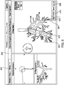
- Activating the "mark position” button 616 causes user interface 216 to present a view 700 including details of the marked position, as shown in FIG. 5 .
- view 700 may indicate a distance to the target center 618 and a biopsy position number 620.
- the clinician may remove LG 92 from EWC 96 and bronchoscope 50 and insert a biopsy tool 102 into bronchoscope 50 and EWC 96 to obtain a tissue sample at the target 604 in step S510.
- the clinician then removes biopsy tool 102 from EWC 96 and bronchoscope 50 and reinserts LG 92.
- the clinician activates a "done" button 624 in view 700 indicating that the biopsy is complete.
- the perform biopsy step S510 and the mark location step S508 may be performed in any order.
- application 81 stores the position marked by virtual probe 612 within the patient's airways and places a virtual marker 622 in both the 3D model 614 and local view 602 of view 600 to mark the location where the tissue sample was obtained.
- the storing of the position and placement of virtual marker 622 may be performed upon activation of the "mark position" button 616 in view 600, during the biopsy, or upon activation of the "done” button 624 in view 700.
- the location where the tissue sample is obtained may also be physically marked by, for example, implanting an echogenic marker or a dye which can be detected in future CT scans of the patient and in some instances compared to the locations of the virtual markers 622 stored in the CT image data and/or the navigation plan.
- the clinician may remove biopsy tool 102 from bronchoscope 50 and provide the tissue sample to a rapid on-site evaluation (“ROSE”) clinician for immediate testing or submit to a lab for routine testing.
- ROSE rapid on-site evaluation
- the clinician determines in step S512 whether another biopsy needs to be performed at target 604. If another biopsy needs to be performed, the clinician repositions LG 92 relative to target 604 in step S514 using view 600 and repeats steps S508 to S512. If no further biopsies are required for target 604, the clinician determines if there is another target to be biopsied in step S516. For example, the clinician may activate a target selection button 623 of view 600 to see if navigation to another target has been planned. If another target is available, the clinician may activate navigation to the new target by activating target selection button 623 and may repeat steps S506 to S516 for the new target as described above.
- a virtual marker 622 may presented in view 800 for each marked biopsy location and the clinician may return to a specified biopsy location at a later time, for example, upon receiving a result of the ROSE testing to perform further biopsies or treatment.
- the virtual marker 622 may be saved as part of the navigation plan, and may include additional information relating to the biopsy, such as the date and time when the tissue sample was obtained, the results of related testing performed on the tissue sample, and/or other information related to the biopsy.
- the virtual marker 622 may also be used as a future target for planning additional pathways using the navigation plan. For example, application 81 may automatically create a pathway to stored virtual markers 622 based on the pathway planned for target 604 since the pathway is already known.
- the actual path taken to the virtual marker 622 by the LG 92 may be stored in association with the virtual marker 622.
- the clinician may also select which virtual markers 622 are displayed by activating a virtual marker menu 626 and selecting a virtual marker position 628 corresponding to the biopsy position number 620 from view 616, as shown, for example, in FIG. 4 .
Landscapes
- Health & Medical Sciences (AREA)
- Life Sciences & Earth Sciences (AREA)
- Engineering & Computer Science (AREA)
- Medical Informatics (AREA)
- Surgery (AREA)
- Nuclear Medicine, Radiotherapy & Molecular Imaging (AREA)
- General Health & Medical Sciences (AREA)
- Veterinary Medicine (AREA)
- Public Health (AREA)
- Animal Behavior & Ethology (AREA)
- Molecular Biology (AREA)
- Biomedical Technology (AREA)
- Heart & Thoracic Surgery (AREA)
- Radiology & Medical Imaging (AREA)
- Pathology (AREA)
- Biophysics (AREA)
- Optics & Photonics (AREA)
- Physics & Mathematics (AREA)
- High Energy & Nuclear Physics (AREA)
- Pulmonology (AREA)
- Oral & Maxillofacial Surgery (AREA)
- Dentistry (AREA)
- Theoretical Computer Science (AREA)
- Human Computer Interaction (AREA)
- Robotics (AREA)
- Endoscopes (AREA)
- Apparatus For Radiation Diagnosis (AREA)
- Otolaryngology (AREA)
- Physiology (AREA)
Description
- The present disclosure relates to biopsy location marking and to systems for marking the location of a biopsy on a bronchial tree model.
- A common device for inspecting the airway of a patient is a bronchoscope. Typically, the bronchoscope is inserted into a patient's airways through the patient's nose or mouth and can extend into the lungs of the patient. A typical bronchoscope includes an elongated flexible tube having an illumination assembly for illuminating the region distal to the bronchoscope's tip, an imaging assembly for providing a video image from the bronchoscope's tip, and a working channel through which instruments, e.g., diagnostic instruments such as biopsy tools, therapeutic instruments can be inserted.
- Bronchoscopes, however, are limited in how far they may be advanced through the airways due to their size. Where the bronchoscope is too large to reach a target location deep in the lungs a clinician may utilize certain real-time imaging modalities such as fluoroscopy. Fluoroscopic images, while useful present certain drawbacks for navigation as it is often difficult to distinguish luminal passageways from solid tissue. Moreover, the images generated by the fluoroscope are two-dimensional whereas navigating the airways of a patient requires the ability to maneuver in three dimensions.
- To address these issues systems have been developed that enable the development of three-dimensional models of the airways or other luminal networks, typically from a series of computed tomography (CT) images. One such system has been developed as part of the ILOGIC® ELECTROMAGNETIC NAVIGATION BRONCHOSCOPY® (ENB™), system currently sold by Covidien LP. The details of such a system are described in the commonly assigned
U.S. Patent No. 7,233,820, filed on March 29, 2004 by Gilboa and entitled ENDOSCOPE STRUCTURES AND TECHNIQUES FOR NAVIGATING TO A TARGET IN BRANCHED STRUCTURE. - Document
US2007/293721 discloses a system for marking a biopsy location according to the preamble ofclaim 1. While the system as described inU.S. Patent No. 7,233,820 is quite capable, there is always a need for development of improvements and additions to such systems. - The present invention is disclosed in the appended set of claims.
- In an aspect of the present disclosure, the device of the invention is configured to carry out the step of loading a navigation plan into a navigation system with the navigation plan including a CT volume generated from a plurality of CT images, inserting a probe into a patient's airways with the probe including a location sensor in operative communication with the navigation system, registering a sensed location of the probe with the CT volume of the navigation plan, selecting a target in the navigation plan, navigating the probe and location sensor to the target, storing a position of the location sensor in the navigation system as a biopsy location, and performing a biopsy at the stored biopsy location.
- In another aspect of the present disclosure, the device of the invention is configured to carry out the step of placing a virtual marker corresponding to the biopsy location in at least one of a 3D model of the patient's airways generated from the CT volume or a local view of the patient's airways generated from a slice of the CT volume.
- In a further aspect of the present disclosure, it is disclosed a method, which is not part of the invention, which further includes locking the probe relative to the extended working channel.
- In yet a further aspect of the present disclosure, the method, which is not part of the invention, further includes inserting the extended working channel and probe into a bronchoscope, and navigating them together to the target
- In a further aspect of the present disclosure, the method, which is not part of the invention, further includes locking the extended working channel in position at the target when the location sensor is navigated to the target.
- In yet a further aspect of the present disclosure, the method, which is not part of the invention, further includes removing the probe from the extended working channel and inserting a biopsy tool through the extended working channel to the target to perform the biopsy.
- In another aspect of the present disclosure, the method, which is not part of the invention, further includes adjusting a position of the probe relative to the target, storing a second position of the location sensor in the navigation system as a second biopsy location, and performing a second biopsy at the second biopsy location.
- In yet another aspect of the present disclosure, the method, which is not part of the invention, further includes selecting a second target in the navigation plan, navigating the probe and location sensor to the second target, storing a second position of the location sensor in the navigation system as a second biopsy location, and performing a biopsy at the stored second biopsy location.
- In a further aspect of the present disclosure, the method, which is not part of the invention, further includes providing tissue from at least one of the biopsy location or the second biopsy location for rapid on-site evaluation.
- In a further aspect of the present disclosure, the method, which is not part of the invention, further includes receiving results from the rapid on-site evaluation clinician indicating a need to return to at least one of the biopsy location or the second biopsy location, presenting a pathway to at least one of the biopsy location or the second biopsy location as a return target in the navigation plan based on the rapid on-site evaluation, navigating the location sensor to the return target, storing a return position of the location sensor in the navigation system as a return biopsy location, and performing at least one of an additional biopsy or a treatment at the stored return biopsy location.
- In another aspect of the present disclosure, the method which is not part of the invention, further includes storing a distance to a center of the target and a biopsy position number with the biopsy location.
- Any of the above aspects and embodiments of the present disclosure may be combined without departing from the scope of the present disclosure.
- Objects and features of the presently disclosed system will become apparent to those of ordinary skill in the art when descriptions of various embodiments thereof are read with reference to the accompanying drawings, of which:
-
FIG. 1 is a perspective view of an electromagnetic navigation system in accordance with the present disclosure; -
FIG. 2 is a schematic diagram of a workstation configured for use with the system ofFIG. 1 ; -
FIG. 3 is a flowchart illustrating a method for marking the location of a biopsy on a 3D model provided in accordance with the present disclosure, which is not part of the invention; -
FIG. 4 is an illustration of a user interface of the workstation ofFIG. 2 presenting a view for marking a biopsy location in accordance with the present disclosure; -
FIG. 5 is an illustration of the user interface of the workstation ofFIG. 2 presenting a view for marking a location of a biopsy or treatment of the target; and -
FIG. 6 is an illustration of the user interface of the workstation ofFIG. 2 presenting a view showing multiple marked biopsy locations. - Systems for marking the location of a biopsy on a three-dimensional (3D) model are provided in accordance with the present disclosure and described in detail below. Various methods for generating the 3D model are envisioned, some of which are more fully described in co-pending
U.S. Patent Application Nos. 13/838,805 13/838,997 13/839,224 U.S. Provisional Patent Application No. 62/020,240 - Additional features of the ENB system of the present disclosure are described in co-pending
U.S. Provisional Patent Application Nos. 62/020,238 62/020,242 62/020,245 62/020,250 62/020,253 62/020,257 62/020,261 62/020,258 62/020,262 - Detailed embodiments of such systems are described below. However, these detailed embodiments are merely examples of the disclosure, which may be embodied in various forms. Therefore, specific structural and functional details disclosed herein are not to be interpreted as limiting, but merely as a basis for the claims and as a representative basis for allowing one skilled in the art to variously employ the present disclosure in virtually any appropriately detailed structure. While the following embodiments are described in terms of bronchoscopy of a patient's airways, those skilled in the art will realize that the same or similar systems may be used in other lumen networks, such as, for example, the vascular, lymphatic, and/or gastrointestinal networks as well.
- With reference to
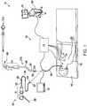
FIG. 1 , an electromagnetic navigation (EMN)system 10 is provided in accordance with the present disclosure. One such ENM system is the ELECTROMAGNETIC NAVIGATION BRONCHOSCOPY® system currently sold by Covidien LP. Among other tasks that may be performed using theEMN system 10 are planning a pathway to target tissue, navigating a positioning assembly to the target tissue, navigating a biopsy tool to the target tissue to obtain a tissue sample from the target tissue using the biopsy tool digitally marking the location where the tissue sample was obtained, and placing one or more echogenic markers at or around the target. - EMN
system 10 generally includes an operating table 40 configured to support a patient; abronchoscope 50 configured for insertion through the patient's mouth and/or nose into the patient's airways;monitoring equipment 60 coupled tobronchoscope 50 for displaying video images received frombronchoscope 50; atracking system 70 including atracking module 72, a plurality ofreference sensors 74, and anelectromagnetic field generator 76; aworkstation 80 including software and/or hardware used to facilitate pathway planning, identification of target tissue, navigation to target tissue, and digitally marking the biopsy location. -
FIG. 1 also depicts two types ofcatheter guide assemblies system 10 and share a number of common components. Eachcatheter guide assembly handle 91, which is connected to an extended working channel (EWC) 96. The EWC 96 is sized for placement into the working channel of abronchoscope 50. In operation, a locatable guide (LG) 92, including an electromagnetic (EM)sensor 94, is inserted into the EWC 96 and locked into position such that thesensor 94 extends a desired distance beyond thedistal tip 93 of the EWC 96. The location of theEM sensor 94, and thus the distal end of the EWC 96, within an electromagnetic field generated by theelectromagnetic field generator 76 can be derived by thetracking module 72, and theworkstation 80. Catheter guide assemblies 90, 100 have different operating mechanisms, but each contain ahandle 91 that can be manipulated by rotation and compression to steer thedistal tip 93 of the LG 92, extended workingchannel 96.Catheter guide assemblies 90 are currently marketed and sold by Covidien LP under the name SUPERDIMENSION® Procedure Kits. Similarlycatheter guide assemblies 100 are currently sold by Covidien LP under the name EDGE™ Procedure Kits. Both kits include ahandle 91, extended workingchannel 96, andlocatable guide 92. For a more detailed description of thecatheter guide assemblies U.S. Patent Application Serial No. 13/836,203 filed on March 15, 2013 - As illustrated in
FIG. 1 , the patient is shown lying on operating table 40 withbronchoscope 50 inserted through the patient's mouth and into the patient's airways. Bronchoscope 50 includes a source of illumination and a video imaging system (not explicitly shown) and is coupled to monitoringequipment 60, e.g., a video display, for displaying the video images received from the video imaging system ofbronchoscope 50. -
Catheter guide assemblies LG 92 andEWC 96 are configured for insertion through a working channel ofbronchoscope 50 into the patient's airways (although thecatheter guide assemblies LG 92 andEWC 96 are selectively lockable relative to one another via alocking mechanism 99. A six degrees-of-freedomelectromagnetic tracking system 70, e.g., similar to those disclosed inU.S. Patent No. 6,188,355 and publishedPCT Application Nos. WO 00/10456 WO 01/67035 Tracking system 70 is configured for use withcatheter guide assemblies EM sensor 94 as it moves in conjunction with theEWC 96 through the airways of the patient, as detailed below. - As shown in
FIG. 1 ,electromagnetic field generator 76 is positioned beneath the patient.Electromagnetic field generator 76 and the plurality ofreference sensors 74 are interconnected withtracking module 72, which derives the location of eachreference sensor 74 in six degrees of freedom. One or more ofreference sensors 74 are attached to the chest of the patient. The six degrees of freedom coordinates ofreference sensors 74 are sent toworkstation 80, which includesapplication 81 wheresensors 74 are used to calculate a patient coordinate frame of reference. - Also shown in
FIG. 1 is acatheter biopsy tool 102 that is insertable into thecatheter guide assemblies LG 92. Thebiopsy tool 102 is used to collect one or more tissue sample from the target tissue. As detailed below,biopsy tool 102 is further configured for use in conjunction with trackingsystem 70 to facilitate navigation ofbiopsy tool 102 to the target tissue, tracking of a location ofbiopsy tool 102 as it is manipulated relative to the target tissue to obtain the tissue sample, and/or marking the location where the tissue sample was obtained. - Although navigation is detailed above with respect to
EM sensor 94 being included in theLG 92 it is also envisioned thatEM sensor 94 may be embedded or incorporated withinbiopsy tool 102 wherebiopsy tool 102 may alternatively be utilized for navigation without need of the LG or the necessary tool exchanges that use of the LG requires. A variety of useable biopsy tools are described inU.S. Provisional Patent Application Nos. 61/906,732 61/906,762 U.S. Provisional Patent Application No. 61/955,407 EMN system 10 as described herein. - During procedure planning,
workstation 80 utilizes computed tomographic (CT) image data for generating and viewing a three-dimensional model ("3D model") of the patient's airways, enables the identification of target tissue on the 3D model (automatically, semi-automatically or manually), and allows for the selection of a pathway through the patient's airways to the target tissue. More specifically, the CT scans are processed and assembled into a 3D volume, which is then utilized to generate the 3D model of the patient's airways. The 3D model may be presented on adisplay monitor 81 associated withworkstation 80, or in any other suitable fashion. Usingworkstation 80, various slices of the 3D volume and views of the 3D model may be presented and/or may be manipulated by a clinician to facilitate identification of a target and selection of a suitable pathway through the patient's airways to access the target. The 3D model may also show marks of the locations where previous biopsies were performed, including the dates, times, and other identifying information regarding the tissue samples obtained. These marks may also be selected as targets to which a pathway can be planned. Once selected, the pathway is saved for use during the navigation procedure. An example of a suitable pathway planning system and method is described inU.S. Patent Application Serial Nos. 13/838,805 13/838,997 13/839,224 - During navigation,
EM sensor 94, in conjunction with trackingsystem 70, enables tracking ofEM sensor 94 and/orbiopsy tool 102 asEM sensor 94 orbiopsy tool 102 is advanced through the patient's airways. - Turning now to
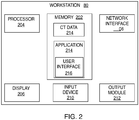
FIG. 2 , there is shown a system diagram ofworkstation 80.Workstation 80 may includememory 202,processor 204,display 206, network interface 208,input device 210, and/oroutput module 212. -
Memory 202 includes any non-transitory computer-readable storage media for storing data and/or software that is executable byprocessor 204 and which controls the operation ofworkstation 80. In an embodiment,memory 202 may include one or more solid-state storage devices such as flash memory chips. Alternatively or in addition to the one or more solid-state storage devices,memory 202 may include one or more mass storage devices connected to theprocessor 204 through a mass storage controller (not shown) and a communications bus (not shown). Although the description of computer-readable media contained herein refers to a solid-state storage, it should be appreciated by those skilled in the art that computer-readable storage media can be any available media that can be accessed by theprocessor 204. That is, computer readable storage media includes non-transitory, volatile and non-volatile, removable and non-removable media implemented in any method or technology for storage of information such as computer-readable instructions, data structures, program modules or other data. For example, computer-readable storage media includes RAM, ROM, EPROM, EEPROM, flash memory or other solid state memory technology, CD-ROM, DVD, Blu-Ray or other optical storage, magnetic cassettes, magnetic tape, magnetic disk storage or other magnetic storage devices, or any other medium which can be used to store the desired information and which can be accessed byworkstation 80. -
Memory 202 may storeapplication 81 and/orCT data 214.Application 81 may, when executed byprocessor 204,cause display 206 to presentuser interface 216. Network interface 208 may be configured to connect to a network such as a local area network (LAN) consisting of a wired network and/or a wireless network, a wide area network (WAN), a wireless mobile network, a Bluetooth network, and/or the internet.Input device 210 may be any device by means of which a user may interact withworkstation 80, such as, for example, a mouse, keyboard, foot pedal, touch screen, and/or voice interface.Output module 212 may include any connectivity port or bus, such as, for example, parallel ports, serial ports, universal serial busses (USB), or any other similar connectivity port known to those skilled in the art. - Referring now to
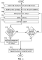
FIG. 3 , there is shown a flowchart of an example method for digitally marking the location where a tissue sample is obtained during a biopsy procedure. Prior to the start of navigation, the clinician loads a navigation plan intoapplication 81 frommemory 202, a USB device, or from network interface 208. Initially,LG 92 andEWC 96 are locked together via lockingmechanism 99 and inserted intobronchoscope 50 such thatEM sensor 94 projects from the distal end ofbronchoscope 50. The clinician then insertsbronchoscope 50 into the patient in step S502.Bronchoscope 50 may, for example, be inserted via the patient's mouth or nose. Alternatively,EM sensor 94 may be embedded within the distal tip ofEWC 96 and may operate independently ofLG 92. - The clinician advances
bronchoscope 50,LG 92, andEWC 96 into each region of the patient's airways in step S504 until registration has occurred between the location ofEM sensor 94 ofLG 92 and the 3D volume of the navigation plan. Further disclosure of the process of registration is disclosed inU.S. Patent Application No. 62/020,220 - Once registration is complete,
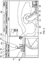
user interface 216 presents the clinician with aview 600 as shown inFIG. 4 to assist the clinician in navigatingLG 92 andEWC 96 to thetarget 604. View 600 may include alocal view 602, a 3D mapdynamic view 606, and abronchoscope view 608.Local view 602 presents the clinician with aslice 610 of the 3D volume located at and aligned with thedistal tip 93 ofLG 92. Theslice 610 is presented from an elevated perspective.Local view 602 also presents the clinician with a visualization of thedistal tip 93 ofLG 92 in the form of avirtual probe 612.Virtual probe 612 provides the clinician with an indication of the direction thatdistal tip 93 ofLG 92 is facing so that the clinician can control the advancement of theLG 92 andEWC 96 in the patient's airways. - 3D map
dynamic view 606 presents adynamic 3D model 614 of the patient's airways generated from the 3D volume of the loaded navigation plan. The orientation ofdynamic 3D model 614 automatically updates based on movement of theEM sensor 94 within the patient's airways to provide the clinician with a view of thedynamic 3D model 614 that is relatively unobstructed by airway branches that are not on the pathway to thetarget 604. 3D mapdynamic view 606 also presents thevirtual probe 612 to the clinician as described above where thevirtual probe 612 rotates and moves through the airways presented in thedynamic 3D model 606 as the clinician advances theEM sensor 94 through corresponding patient airways. -
Bronchoscope view 608 presents the clinician with a real-time image received from thebronchoscope 50 and allows the clinician to visually observe the patient's airways in real-time asbronchoscope 50 is navigated through the patient's airways towardtarget 604. - The clinician navigates
bronchoscope 50 toward thetarget 604 until the patient's airways become too small forbronchoscope 50 to pass and wedges bronchoscope 50 in place.LG 92 andEWC 96 are then extended frombronchoscope 50 and the clinician navigatesLG 92 andEWC 96 toward thetarget 604 usingview 600 ofuser interface 216 untilvirtual probe 612 is adjacent to or inserted intotarget 604, as shown, for example, inFIG. 4 . - The clinician then begins the biopsy by activating a "mark position"
button 614 to virtually mark the position ofvirtual probe 612 in the 3D volume which corresponds to the registered position ofEM sensor 94 in step S508. Activating the "mark position"button 616 causesuser interface 216 to present aview 700 including details of the marked position, as shown inFIG. 5 . For example, view 700 may indicate a distance to thetarget center 618 and abiopsy position number 620. - After activating the "mark position"
button 616, the clinician may removeLG 92 fromEWC 96 andbronchoscope 50 and insert abiopsy tool 102 intobronchoscope 50 andEWC 96 to obtain a tissue sample at thetarget 604 in step S510. In some embodiments, the clinician then removesbiopsy tool 102 fromEWC 96 andbronchoscope 50 and reinsertsLG 92. WhenLG 92 reaches the distal end ofEWC 96, the clinician activates a "done"button 624 inview 700 indicating that the biopsy is complete. Though described herein in a specific order, the perform biopsy step S510 and the mark location step S508 may be performed in any order. - During the biopsy,
application 81 stores the position marked byvirtual probe 612 within the patient's airways and places avirtual marker 622 in both the3D model 614 andlocal view 602 ofview 600 to mark the location where the tissue sample was obtained. The storing of the position and placement ofvirtual marker 622 may be performed upon activation of the "mark position"button 616 inview 600, during the biopsy, or upon activation of the "done"button 624 inview 700. Additionally, the location where the tissue sample is obtained may also be physically marked by, for example, implanting an echogenic marker or a dye which can be detected in future CT scans of the patient and in some instances compared to the locations of thevirtual markers 622 stored in the CT image data and/or the navigation plan. After the tissue sample is obtained and the location is marked, the clinician may removebiopsy tool 102 frombronchoscope 50 and provide the tissue sample to a rapid on-site evaluation ("ROSE") clinician for immediate testing or submit to a lab for routine testing. - The clinician determines in step S512 whether another biopsy needs to be performed at
target 604. If another biopsy needs to be performed, the clinician repositionsLG 92 relative to target 604 in stepS514 using view 600 and repeats steps S508 to S512. If no further biopsies are required fortarget 604, the clinician determines if there is another target to be biopsied in step S516. For example, the clinician may activate atarget selection button 623 ofview 600 to see if navigation to another target has been planned. If another target is available, the clinician may activate navigation to the new target by activatingtarget selection button 623 and may repeat steps S506 to S516 for the new target as described above. - As illustrated in
FIG. 6 , avirtual marker 622 may presented inview 800 for each marked biopsy location and the clinician may return to a specified biopsy location at a later time, for example, upon receiving a result of the ROSE testing to perform further biopsies or treatment. Thevirtual marker 622 may be saved as part of the navigation plan, and may include additional information relating to the biopsy, such as the date and time when the tissue sample was obtained, the results of related testing performed on the tissue sample, and/or other information related to the biopsy. Thevirtual marker 622 may also be used as a future target for planning additional pathways using the navigation plan. For example,application 81 may automatically create a pathway to storedvirtual markers 622 based on the pathway planned fortarget 604 since the pathway is already known. Alternatively, the actual path taken to thevirtual marker 622 by theLG 92 may be stored in association with thevirtual marker 622. The clinician may also select whichvirtual markers 622 are displayed by activating avirtual marker menu 626 and selecting avirtual marker position 628 corresponding to thebiopsy position number 620 fromview 616, as shown, for example, inFIG. 4 . - While several embodiments of the disclosure have been shown in the drawings, it is not intended that the disclosure be limited thereto, as it is intended that the disclosure be as broad in scope as the art will allow and that the specification be read likewise. Therefore, the above description should not be construed as limiting but merely as exemplifications of particular embodiments. Those skilled in the art will envision other modifications within the scope of the claims appended hereto.
Claims (6)
- A system for marking a biopsy location in a representation of a patient's airways, the system comprising:a navigation system (10) including a navigation plan which includes a CT volume generated from a plurality of CT images;a probe (92) for insertion into a patient's airways, the probe including a location sensor (94) in operative communication with the navigation system; andthe system configured to carry out the steps ofregistering a sensed location of the probe with the CT volume of the navigation plan;selecting or enabling the selection of a target in the navigation plan;storing a position of the location sensor in the navigation system when at the target as a biopsy location; and said system being characterized in that it further comprises the step ofpresenting a view (602) of a 3D volume which corresponds to the registered location of the sensor (94), the view including a virtual probe (612) which provides a visualization of the distal tip (93) of the probe (94) and indicates the direction that the distal tip (93) of the probe (92) is facing.
- The system according to claim 1, wherein the system is further configured to place a virtual marker corresponding to the biopsy location in at least one of a 3D model of the patient's airways generated from the CT volume or a local view of the patient's airways generated from a slice of the CT volume.
- The system according to claim 1, wherein the system is further configured to store a second position of the location sensor in the navigation system as a second biopsy location.
- The system according to claim 1, wherein the system is further configured to carry out the steps of:selecting a second target in the navigation plan;storing a second position of the location sensor when at the target in the navigation system as a second biopsy location.
- The system according to claim 4, wherein the system is further configured to carry out the steps of:reselecting at least one of the biopsy location or the second biopsy location;presenting a pathway to the reselected at least one of the biopsy location or the second biopsy location as a return target in the navigation plan; andstoring a return position of the location sensor when at the reselected target in the navigation system as a return biopsy location.
- The system according to claim 1, wherein the system is further configured to store a distance to a center of the target and a biopsy position number with the biopsy location.
Applications Claiming Priority (3)
| Application Number | Priority Date | Filing Date | Title |
|---|---|---|---|
| US201462020177P | 2014-07-02 | 2014-07-02 | |
| US14/753,229 US20160000414A1 (en) | 2014-07-02 | 2015-06-29 | Methods for marking biopsy location |
| PCT/US2015/038464 WO2016003990A2 (en) | 2014-07-02 | 2015-06-30 | Methods for marking biopsy location |
Publications (3)
| Publication Number | Publication Date |
|---|---|
| EP3164052A2 EP3164052A2 (en) | 2017-05-10 |
| EP3164052A4 EP3164052A4 (en) | 2018-03-21 |
| EP3164052B1 true EP3164052B1 (en) | 2020-09-02 |
Family
ID=55016158
Family Applications (1)
| Application Number | Title | Priority Date | Filing Date |
|---|---|---|---|
| EP15815581.2A Active EP3164052B1 (en) | 2014-07-02 | 2015-06-30 | Systems for marking biopsy location |
Country Status (7)
| Country | Link |
|---|---|
| US (3) | US20160000414A1 (en) |
| EP (1) | EP3164052B1 (en) |
| JP (1) | JP6635952B2 (en) |
| CN (1) | CN106793938B (en) |
| AU (1) | AU2015284273A1 (en) |
| CA (1) | CA2953400A1 (en) |
| WO (1) | WO2016003990A2 (en) |
Families Citing this family (71)
| Publication number | Priority date | Publication date | Assignee | Title |
|---|---|---|---|---|
| US9254123B2 (en) | 2009-04-29 | 2016-02-09 | Hansen Medical, Inc. | Flexible and steerable elongate instruments with shape control and support elements |
| US8672837B2 (en) | 2010-06-24 | 2014-03-18 | Hansen Medical, Inc. | Methods and devices for controlling a shapeable medical device |
| US20120071894A1 (en) | 2010-09-17 | 2012-03-22 | Tanner Neal A | Robotic medical systems and methods |
| US10149720B2 (en) | 2013-03-08 | 2018-12-11 | Auris Health, Inc. | Method, apparatus, and a system for facilitating bending of an instrument in a surgical or medical robotic environment |
| US9057600B2 (en) | 2013-03-13 | 2015-06-16 | Hansen Medical, Inc. | Reducing incremental measurement sensor error |
| US9014851B2 (en) | 2013-03-15 | 2015-04-21 | Hansen Medical, Inc. | Systems and methods for tracking robotically controlled medical instruments |
| US10376672B2 (en) | 2013-03-15 | 2019-08-13 | Auris Health, Inc. | Catheter insertion system and method of fabrication |
| US9629595B2 (en) | 2013-03-15 | 2017-04-25 | Hansen Medical, Inc. | Systems and methods for localizing, tracking and/or controlling medical instruments |
| US9271663B2 (en) | 2013-03-15 | 2016-03-01 | Hansen Medical, Inc. | Flexible instrument localization from both remote and elongation sensors |
| US11020016B2 (en) | 2013-05-30 | 2021-06-01 | Auris Health, Inc. | System and method for displaying anatomy and devices on a movable display |
| US9763741B2 (en) * | 2013-10-24 | 2017-09-19 | Auris Surgical Robotics, Inc. | System for robotic-assisted endolumenal surgery and related methods |
| EP2923669B1 (en) | 2014-03-24 | 2017-06-28 | Hansen Medical, Inc. | Systems and devices for catheter driving instinctiveness |
| US9744335B2 (en) | 2014-07-01 | 2017-08-29 | Auris Surgical Robotics, Inc. | Apparatuses and methods for monitoring tendons of steerable catheters |
| US9561083B2 (en) | 2014-07-01 | 2017-02-07 | Auris Surgical Robotics, Inc. | Articulating flexible endoscopic tool with roll capabilities |
| US10792464B2 (en) | 2014-07-01 | 2020-10-06 | Auris Health, Inc. | Tool and method for using surgical endoscope with spiral lumens |
| US11188285B2 (en) | 2014-07-02 | 2021-11-30 | Covidien Lp | Intelligent display |
| US9603668B2 (en) | 2014-07-02 | 2017-03-28 | Covidien Lp | Dynamic 3D lung map view for tool navigation inside the lung |
| US9633431B2 (en) | 2014-07-02 | 2017-04-25 | Covidien Lp | Fluoroscopic pose estimation |
| AU2015283938B2 (en) | 2014-07-02 | 2019-08-08 | Covidien Lp | Alignment CT |
| US10314463B2 (en) | 2014-10-24 | 2019-06-11 | Auris Health, Inc. | Automated endoscope calibration |
| US11819636B2 (en) | 2015-03-30 | 2023-11-21 | Auris Health, Inc. | Endoscope pull wire electrical circuit |
| EP4070723A1 (en) | 2015-09-18 | 2022-10-12 | Auris Health, Inc. | Navigation of tubular networks |
| US10143526B2 (en) | 2015-11-30 | 2018-12-04 | Auris Health, Inc. | Robot-assisted driving systems and methods |
| US11419490B2 (en) | 2016-08-02 | 2022-08-23 | Covidien Lp | System and method of using an endoscopic catheter as a port in laparoscopic surgery |
| US10463439B2 (en) | 2016-08-26 | 2019-11-05 | Auris Health, Inc. | Steerable catheter with shaft load distributions |
| US10939963B2 (en) | 2016-09-01 | 2021-03-09 | Covidien Lp | Systems and methods for providing proximity awareness to pleural boundaries, vascular structures, and other critical intra-thoracic structures during electromagnetic navigation bronchoscopy |
| US10543044B2 (en) | 2016-09-27 | 2020-01-28 | Covidien Lp | Systems and methods for detecting pleural invasion for surgical and interventional planning |
| US10542953B2 (en) | 2016-09-27 | 2020-01-28 | Covidien Lp | Fissural assessment and surgical and interventional planning |
| WO2018060404A1 (en) | 2016-09-29 | 2018-04-05 | Koninklijke Philips N.V. | System and method for planning and performing an interventional procedure based on the spatial relationships between identified points |
| US9931025B1 (en) | 2016-09-30 | 2018-04-03 | Auris Surgical Robotics, Inc. | Automated calibration of endoscopes with pull wires |
| CN106539624B (en) * | 2016-11-23 | 2019-12-03 | 常州朗合医疗器械有限公司 | Medical path air navigation aid, method and system for planning |
| US11653853B2 (en) | 2016-11-29 | 2023-05-23 | Biosense Webster (Israel) Ltd. | Visualization of distances to walls of anatomical cavities |
| US10244926B2 (en) | 2016-12-28 | 2019-04-02 | Auris Health, Inc. | Detecting endolumenal buckling of flexible instruments |
| US11547318B2 (en) | 2017-01-03 | 2023-01-10 | Koninklijke Philips N.V. | Medical navigation system using shape-sensing device and method of operation thereof |
| AU2018243364B2 (en) | 2017-03-31 | 2023-10-05 | Auris Health, Inc. | Robotic systems for navigation of luminal networks that compensate for physiological noise |
| US11571262B2 (en) * | 2017-04-18 | 2023-02-07 | Intuitive Surgical Operations, Inc. | Graphical user interface for planning a procedure |
| CN110831498B (en) * | 2017-05-12 | 2022-08-12 | 奥瑞斯健康公司 | Biopsy device and system |
| AU2018270785B2 (en) | 2017-05-17 | 2023-11-23 | Auris Health, Inc. | Exchangeable working channel |
| US11583222B2 (en) * | 2017-05-19 | 2023-02-21 | Covidien Lp | Systems, devices, and methods for lymph specimen tracking, drainage determination, visualization, and treatment |
| US10390891B2 (en) * | 2017-06-13 | 2019-08-27 | Biosense Webster (Israel) Ltd. | Hologram lens for positioning an orthopedic implant |
| US10022192B1 (en) | 2017-06-23 | 2018-07-17 | Auris Health, Inc. | Automatically-initialized robotic systems for navigation of luminal networks |
| US10426559B2 (en) | 2017-06-30 | 2019-10-01 | Auris Health, Inc. | Systems and methods for medical instrument compression compensation |
| US10145747B1 (en) | 2017-10-10 | 2018-12-04 | Auris Health, Inc. | Detection of undesirable forces on a surgical robotic arm |
| US11058493B2 (en) | 2017-10-13 | 2021-07-13 | Auris Health, Inc. | Robotic system configured for navigation path tracing |
| US10555778B2 (en) | 2017-10-13 | 2020-02-11 | Auris Health, Inc. | Image-based branch detection and mapping for navigation |
| CN110831536B (en) | 2017-12-06 | 2021-09-07 | 奥瑞斯健康公司 | System and method for correcting for a non-commanded instrument roll |
| CN110869173B (en) | 2017-12-14 | 2023-11-17 | 奥瑞斯健康公司 | System and method for estimating instrument positioning |
| KR20200101334A (en) | 2017-12-18 | 2020-08-27 | 아우리스 헬스, 인코포레이티드 | Method and system for tracking and navigation of instruments in the luminal network |
| US11464576B2 (en) | 2018-02-09 | 2022-10-11 | Covidien Lp | System and method for displaying an alignment CT |
| US20190298305A1 (en) * | 2018-03-28 | 2019-10-03 | Covidien Lp | Electromagnetic navigation bronchoscopy using ultrasound |
| JP7214747B2 (en) | 2018-03-28 | 2023-01-30 | オーリス ヘルス インコーポレイテッド | System and method for position sensor alignment |
| US10827913B2 (en) | 2018-03-28 | 2020-11-10 | Auris Health, Inc. | Systems and methods for displaying estimated location of instrument |
| US11109920B2 (en) | 2018-03-28 | 2021-09-07 | Auris Health, Inc. | Medical instruments with variable bending stiffness profiles |
| WO2019231895A1 (en) | 2018-05-30 | 2019-12-05 | Auris Health, Inc. | Systems and methods for location sensor-based branch prediction |
| WO2019231891A1 (en) | 2018-05-31 | 2019-12-05 | Auris Health, Inc. | Path-based navigation of tubular networks |
| KR102455671B1 (en) | 2018-05-31 | 2022-10-20 | 아우리스 헬스, 인코포레이티드 | Image-Based Airway Analysis and Mapping |
| CN112236083A (en) | 2018-05-31 | 2021-01-15 | 奥瑞斯健康公司 | Robotic system and method for navigating a luminal network detecting physiological noise |
| US10898276B2 (en) | 2018-08-07 | 2021-01-26 | Auris Health, Inc. | Combining strain-based shape sensing with catheter control |
| WO2020068853A2 (en) | 2018-09-26 | 2020-04-02 | Auris Health, Inc. | Articulating medical instruments |
| KR20210073542A (en) | 2018-09-28 | 2021-06-18 | 아우리스 헬스, 인코포레이티드 | Systems and methods for docking medical instruments |
| CN113286543A (en) | 2018-12-28 | 2021-08-20 | 奥瑞斯健康公司 | Medical instrument with articulatable segments |
| US11617627B2 (en) | 2019-03-29 | 2023-04-04 | Auris Health, Inc. | Systems and methods for optical strain sensing in medical instruments |
| US11975157B2 (en) | 2019-04-12 | 2024-05-07 | Covidien Lp | Method of manufacturing an elongated catheter having multiple sensors for three-dimensional location of the catheter |
| WO2021028883A1 (en) | 2019-08-15 | 2021-02-18 | Auris Health, Inc. | Medical device having multiple bending sections |
| US11147633B2 (en) | 2019-08-30 | 2021-10-19 | Auris Health, Inc. | Instrument image reliability systems and methods |
| US11207141B2 (en) | 2019-08-30 | 2021-12-28 | Auris Health, Inc. | Systems and methods for weight-based registration of location sensors |
| CN110478038B (en) * | 2019-09-10 | 2024-04-19 | 四川省肿瘤医院 | Adjustable trachea model |
| KR20220123273A (en) | 2019-12-31 | 2022-09-06 | 아우리스 헬스, 인코포레이티드 | Anatomical feature identification and targeting |
| JP2023508525A (en) | 2019-12-31 | 2023-03-02 | オーリス ヘルス インコーポレイテッド | Alignment techniques for percutaneous access |
| CN114901188A (en) | 2019-12-31 | 2022-08-12 | 奥瑞斯健康公司 | Dynamic pulley system |
| WO2021137108A1 (en) | 2019-12-31 | 2021-07-08 | Auris Health, Inc. | Alignment interfaces for percutaneous access |
Family Cites Families (166)
| Publication number | Priority date | Publication date | Assignee | Title |
|---|---|---|---|---|
| ES2115776T3 (en) | 1992-08-14 | 1998-07-01 | British Telecomm | POSITION LOCATION SYSTEM. |
| US6757557B1 (en) | 1992-08-14 | 2004-06-29 | British Telecommunications | Position location system |
| DE4304571A1 (en) | 1993-02-16 | 1994-08-18 | Mdc Med Diagnostic Computing | Procedures for planning and controlling a surgical procedure |
| US5881124A (en) | 1994-03-31 | 1999-03-09 | Arch Development Corporation | Automated method and system for the detection of lesions in medical computed tomographic scans |
| US5803089A (en) | 1994-09-15 | 1998-09-08 | Visualization Technology, Inc. | Position tracking and imaging system for use in medical applications |
| US5829444A (en) | 1994-09-15 | 1998-11-03 | Visualization Technology, Inc. | Position tracking and imaging system for use in medical applications |
| US6694163B1 (en) | 1994-10-27 | 2004-02-17 | Wake Forest University Health Sciences | Method and system for producing interactive, three-dimensional renderings of selected body organs having hollow lumens to enable simulated movement through the lumen |
| US5782762A (en) | 1994-10-27 | 1998-07-21 | Wake Forest University | Method and system for producing interactive, three-dimensional renderings of selected body organs having hollow lumens to enable simulated movement through the lumen |
| US5920319A (en) | 1994-10-27 | 1999-07-06 | Wake Forest University | Automatic analysis in virtual endoscopy |
| US5611025A (en) | 1994-11-23 | 1997-03-11 | General Electric Company | Virtual internal cavity inspection system |
| DE69523543T2 (en) * | 1994-12-13 | 2002-04-04 | Microsoft Corp | Taskbar with start menu |
| US6151404A (en) | 1995-06-01 | 2000-11-21 | Medical Media Systems | Anatomical visualization system |
| US5729129A (en) | 1995-06-07 | 1998-03-17 | Biosense, Inc. | Magnetic location system with feedback adjustment of magnetic field generator |
| US5752513A (en) | 1995-06-07 | 1998-05-19 | Biosense, Inc. | Method and apparatus for determining position of object |
| US5592939A (en) | 1995-06-14 | 1997-01-14 | Martinelli; Michael A. | Method and system for navigating a catheter probe |
| US5697377A (en) | 1995-11-22 | 1997-12-16 | Medtronic, Inc. | Catheter mapping system and method |
| IL125755A (en) | 1996-02-15 | 2003-05-29 | Biosense Inc | Catheter calibration and usage monitoring system |
| CA2246287C (en) | 1996-02-15 | 2006-10-24 | Biosense, Inc. | Medical procedures and apparatus using intrabody probes |
| US5699799A (en) | 1996-03-26 | 1997-12-23 | Siemens Corporate Research, Inc. | Automatic determination of the curved axis of a 3-D tube-shaped object in image volume |
| US6047080A (en) | 1996-06-19 | 2000-04-04 | Arch Development Corporation | Method and apparatus for three-dimensional reconstruction of coronary vessels from angiographic images |
| US6167296A (en) | 1996-06-28 | 2000-12-26 | The Board Of Trustees Of The Leland Stanford Junior University | Method for volumetric image navigation |
| US5971767A (en) | 1996-09-16 | 1999-10-26 | The Research Foundation Of State University Of New York | System and method for performing a three-dimensional virtual examination |
| US5891030A (en) | 1997-01-24 | 1999-04-06 | Mayo Foundation For Medical Education And Research | System for two dimensional and three dimensional imaging of tubular structures in the human body |
| US8682045B2 (en) | 1997-02-25 | 2014-03-25 | Wake Forest University Health Sciences | Virtual endoscopy with improved image segmentation and lesion detection |
| US6346940B1 (en) | 1997-02-27 | 2002-02-12 | Kabushiki Kaisha Toshiba | Virtualized endoscope system |
| US6019725A (en) | 1997-03-07 | 2000-02-01 | Sonometrics Corporation | Three-dimensional tracking and imaging system |
| US6246784B1 (en) | 1997-08-19 | 2001-06-12 | The United States Of America As Represented By The Department Of Health And Human Services | Method for segmenting medical images and detecting surface anomalies in anatomical structures |
| US6181348B1 (en) | 1997-09-22 | 2001-01-30 | Siemens Corporate Research, Inc. | Method for selective volume visualization via texture mapping |
| JPH11155881A (en) | 1997-09-26 | 1999-06-15 | Olympus Optical Co Ltd | Operative path retrieval device |
| US5987960A (en) | 1997-09-26 | 1999-11-23 | Picker International, Inc. | Tool calibrator |
| US6201387B1 (en) | 1997-10-07 | 2001-03-13 | Biosense, Inc. | Miniaturized position sensor having photolithographic coils for tracking a medical probe |
| JP2002504385A (en) | 1998-02-23 | 2002-02-12 | アルゴテック システムズ リミテッド | Automatic route planning method |
| US6167406A (en) * | 1998-05-08 | 2000-12-26 | Allen-Bradley Company, Llc | System, method and article of manufacture for building an enterprise-wide data model |
| US6138045A (en) | 1998-08-07 | 2000-10-24 | Arch Development Corporation | Method and system for the segmentation and classification of lesions |
| DE19854241B4 (en) | 1998-11-24 | 2014-03-06 | Siemens Aktiengesellschaft | A method of displaying images displayed on a display monitor, and a device for processing and reproducing digital images |
| US20010023414A1 (en) * | 1998-12-08 | 2001-09-20 | Srihari Kumar | Interactive calculation and presentation of financial data results through a single interface on a data-packet-network |
| DE69927001T2 (en) | 1999-01-04 | 2006-06-08 | Koninklijke Philips Electronics N.V. | METHOD, SYSTEM AND DEVICE FOR PROCESSING A PICTURE DEVIATED TO A TUBE-STRUCTURE AND FOR DETERMINING A PATH THROUGH THE ABOVEMENTIONED STRUCTURE |
| US6501981B1 (en) | 1999-03-16 | 2002-12-31 | Accuray, Inc. | Apparatus and method for compensating for respiratory and patient motions during treatment |
| US6466815B1 (en) | 1999-03-30 | 2002-10-15 | Olympus Optical Co., Ltd. | Navigation apparatus and surgical operation image acquisition/display apparatus using the same |
| US6233476B1 (en) | 1999-05-18 | 2001-05-15 | Mediguide Ltd. | Medical positioning system |
| US6237604B1 (en) | 1999-09-07 | 2001-05-29 | Scimed Life Systems, Inc. | Systems and methods for preventing automatic identification of re-used single use devices |
| US6387092B1 (en) | 1999-09-07 | 2002-05-14 | Scimed Life Systems, Inc. | Systems and methods to identify and disable re-used single use devices based on time elapsed from first therapeutic use |
| US6651669B1 (en) | 1999-09-07 | 2003-11-25 | Scimed Life Systems, Inc. | Systems and methods to identify and disable re-used single use devices based on cataloging catheter usage |
| US6611793B1 (en) | 1999-09-07 | 2003-08-26 | Scimed Life Systems, Inc. | Systems and methods to identify and disable re-use single use devices based on detecting environmental changes |
| JP2003526407A (en) | 1999-09-08 | 2003-09-09 | キューロン メディカル,インコーポレイテッド | System for controlling a set of treatment devices |
| US6381485B1 (en) | 1999-10-28 | 2002-04-30 | Surgical Navigation Technologies, Inc. | Registration of human anatomy integrated for electromagnetic localization |
| US7366562B2 (en) | 2003-10-17 | 2008-04-29 | Medtronic Navigation, Inc. | Method and apparatus for surgical navigation |
| US6505065B1 (en) | 1999-10-29 | 2003-01-07 | Koninklijke Philips Electronics, N.V. | Methods and apparatus for planning and executing minimally invasive procedures for in-vivo placement of objects |
| US6535756B1 (en) | 2000-04-07 | 2003-03-18 | Surgical Navigation Technologies, Inc. | Trajectory storage apparatus and method for surgical navigation system |
| US7085400B1 (en) | 2000-06-14 | 2006-08-01 | Surgical Navigation Technologies, Inc. | System and method for image based sensor calibration |
| US6650927B1 (en) | 2000-08-18 | 2003-11-18 | Biosense, Inc. | Rendering of diagnostic imaging data on a three-dimensional map |
| US6850794B2 (en) | 2000-09-23 | 2005-02-01 | The Trustees Of The Leland Stanford Junior University | Endoscopic targeting method and system |
| US6925200B2 (en) | 2000-11-22 | 2005-08-02 | R2 Technology, Inc. | Graphical user interface for display of anatomical information |
| US7072501B2 (en) | 2000-11-22 | 2006-07-04 | R2 Technology, Inc. | Graphical user interface for display of anatomical information |
| US6829379B1 (en) | 2000-11-27 | 2004-12-07 | Ge Medical Systems Global Technology Company, Llc | Methods and apparatus to assist and facilitate vessel analysis |
| US7179220B2 (en) | 2001-02-07 | 2007-02-20 | Siemens Corporate Research, Inc. | Method for guiding flexible instrument procedures |
| US7162292B2 (en) * | 2001-05-21 | 2007-01-09 | Olympus Corporation | Beam scanning probe system for surgery |
| EP1260179B1 (en) | 2001-05-22 | 2003-03-26 | BrainLAB AG | X-ray image registration device with a medical navigation system |
| US7324104B1 (en) | 2001-09-14 | 2008-01-29 | The Research Foundation Of State University Of New York | Method of centerline generation in virtual objects |
| US8126241B2 (en) | 2001-10-15 | 2012-02-28 | Michael Zarkh | Method and apparatus for positioning a device in a tubular organ |
| US7397937B2 (en) | 2001-11-23 | 2008-07-08 | R2 Technology, Inc. | Region growing in anatomical images |
| US7336809B2 (en) | 2001-11-23 | 2008-02-26 | R2 Technology, Inc. | Segmentation in medical images |
| US6947786B2 (en) | 2002-02-28 | 2005-09-20 | Surgical Navigation Technologies, Inc. | Method and apparatus for perspective inversion |
| US6774624B2 (en) | 2002-03-27 | 2004-08-10 | Ge Medical Systems Global Technology Company, Llc | Magnetic tracking system |
| US7006677B2 (en) | 2002-04-15 | 2006-02-28 | General Electric Company | Semi-automatic segmentation algorithm for pet oncology images |
| CN1658789A (en) * | 2002-04-17 | 2005-08-24 | 超级测量有限公司 | Endoscope structures and techniques for navigating to a target in branched structure |
| US7998062B2 (en) | 2004-03-29 | 2011-08-16 | Superdimension, Ltd. | Endoscope structures and techniques for navigating to a target in branched structure |
| US7630752B2 (en) | 2002-08-06 | 2009-12-08 | Stereotaxis, Inc. | Remote control of medical devices using a virtual device interface |
| US6892090B2 (en) | 2002-08-19 | 2005-05-10 | Surgical Navigation Technologies, Inc. | Method and apparatus for virtual endoscopy |
| US8862204B2 (en) | 2002-11-18 | 2014-10-14 | Mediguide Ltd. | Reducing mechanical stress on conductors and connection points in a position determinable interventional medical device |
| US6898263B2 (en) | 2002-11-27 | 2005-05-24 | Ge Medical Systems Global Technology Company, Llc | Method and apparatus for soft-tissue volume visualization |
| US7505809B2 (en) | 2003-01-13 | 2009-03-17 | Mediguide Ltd. | Method and system for registering a first image with a second image relative to the body of a patient |
| US20050033117A1 (en) | 2003-06-02 | 2005-02-10 | Olympus Corporation | Object observation system and method of controlling object observation system |
| US7822461B2 (en) * | 2003-07-11 | 2010-10-26 | Siemens Medical Solutions Usa, Inc. | System and method for endoscopic path planning |
| US8055323B2 (en) | 2003-08-05 | 2011-11-08 | Imquant, Inc. | Stereotactic system and method for defining a tumor treatment region |
| JP3820244B2 (en) | 2003-10-29 | 2006-09-13 | オリンパス株式会社 | Insertion support system |
| WO2005041761A1 (en) | 2003-10-31 | 2005-05-12 | Olympus Corporation | Insertion support system |
| JP4323288B2 (en) * | 2003-10-31 | 2009-09-02 | オリンパス株式会社 | Insertion support system |
| JP3847744B2 (en) | 2003-11-04 | 2006-11-22 | オリンパス株式会社 | Insertion support system |
| US7901348B2 (en) * | 2003-12-12 | 2011-03-08 | University Of Washington | Catheterscope 3D guidance and interface system |
| US7315639B2 (en) | 2004-03-03 | 2008-01-01 | Mevis Gmbh | Method of lung lobe segmentation and computer system |
| WO2005084571A1 (en) | 2004-03-03 | 2005-09-15 | Deutsches Krebsforschungszentrum Stiftung des öffentlichen Rechts | Incremental real time recording of tracked instruments in tubular organ structures inside the human body |
| US7811294B2 (en) | 2004-03-08 | 2010-10-12 | Mediguide Ltd. | Automatic guidewire maneuvering system and method |
| US8409167B2 (en) | 2004-07-19 | 2013-04-02 | Broncus Medical Inc | Devices for delivering substances through an extra-anatomic opening created in an airway |
| US7428334B2 (en) | 2004-08-27 | 2008-09-23 | General Electric Company | Methods and systems for 3D segmentation of ultrasound images |
| US7373271B1 (en) | 2004-09-20 | 2008-05-13 | Ascension Technology Corporation | System and method for measuring position and orientation using distortion-compensated magnetic fields |
| US7452357B2 (en) | 2004-10-22 | 2008-11-18 | Ethicon Endo-Surgery, Inc. | System and method for planning treatment of tissue |
| US7805269B2 (en) | 2004-11-12 | 2010-09-28 | Philips Electronics Ltd | Device and method for ensuring the accuracy of a tracking device in a volume |
| JP4914574B2 (en) | 2005-04-18 | 2012-04-11 | オリンパスメディカルシステムズ株式会社 | Endoscope shape detection device |
| US7236558B2 (en) | 2005-07-07 | 2007-06-26 | Terarecon, Inc. | Three-dimensional image display device creating three-dimensional image directly from projection data |
| KR20080031929A (en) | 2005-08-04 | 2008-04-11 | 코닌클리케 필립스 일렉트로닉스 엔.브이. | System and method for magnetic tracking of a sensor for interventional device localization |
| DE102005037000B4 (en) | 2005-08-05 | 2011-06-01 | Siemens Ag | Device for the automated planning of an access path for a percutaneous, minimally invasive procedure |
| JP4232045B2 (en) * | 2005-08-22 | 2009-03-04 | 日本電気株式会社 | Information processing apparatus, program, and display control method |
| US7301332B2 (en) | 2005-10-06 | 2007-11-27 | Biosense Webster, Inc. | Magnetic sensor assembly |
| US7702153B2 (en) | 2005-10-07 | 2010-04-20 | Siemens Medical Solutions Usa, Inc. | Systems and methods for segmenting object of interest from medical image |
| US7518619B2 (en) | 2005-11-07 | 2009-04-14 | General Electric Company | Method and apparatus for integrating three-dimensional and two-dimensional monitors with medical diagnostic imaging workstations |
| US7756316B2 (en) | 2005-12-05 | 2010-07-13 | Siemens Medicals Solutions USA, Inc. | Method and system for automatic lung segmentation |
| US7907772B2 (en) | 2006-03-30 | 2011-03-15 | Accuray Incorporated | Delineation on three-dimensional medical image |
| US8208708B2 (en) | 2006-03-30 | 2012-06-26 | Koninklijke Philips Electronics N.V. | Targeting method, targeting device, computer readable medium and program element |
| WO2007129616A1 (en) | 2006-05-02 | 2007-11-15 | National University Corporation Nagoya University | Insertion assist system of endoscope and insertion assist method of endoscope |
| US8199981B2 (en) | 2006-05-18 | 2012-06-12 | Elekta Ltd. | Methods and systems for segmentation using boundary reparameterization |
| JP5457178B2 (en) | 2006-06-30 | 2014-04-02 | ブロンカス テクノロジーズ, インコーポレイテッド | Airway bypass site selection and treatment planning |
| US8267927B2 (en) | 2007-01-24 | 2012-09-18 | Koninklijke Philips Electronics N.V. | Advanced ablation planning |
| US8672836B2 (en) | 2007-01-31 | 2014-03-18 | The Penn State Research Foundation | Method and apparatus for continuous guidance of endoscopy |
| US9037215B2 (en) | 2007-01-31 | 2015-05-19 | The Penn State Research Foundation | Methods and apparatus for 3D route planning through hollow organs |
| EP2358269B1 (en) | 2007-03-08 | 2019-04-10 | Sync-RX, Ltd. | Image processing and tool actuation for medical procedures |
| WO2008111070A2 (en) * | 2007-03-12 | 2008-09-18 | David Tolkowsky | Devices and methods for performing medical procedures in tree-like luminal structures |
| JP4545169B2 (en) | 2007-04-12 | 2010-09-15 | 富士フイルム株式会社 | Image display method, apparatus and program |
| US8798339B2 (en) | 2007-05-10 | 2014-08-05 | Koninklijke Philips N.V. | Targeting method, targeting device, computer readable medium and program element |
| US20090012390A1 (en) | 2007-07-02 | 2009-01-08 | General Electric Company | System and method to improve illustration of an object with respect to an imaged subject |
| US8730237B2 (en) | 2007-08-03 | 2014-05-20 | Koninklijke Philips N.V. | Coupling the viewing direction of a blood vessel's CPR view with the viewing angle on the 3D tubular structure's rendered voxel volume and/or with the C-arm geometry of a 3D rotational angiography device's C-arm system |
| US8009891B2 (en) | 2007-09-27 | 2011-08-30 | General Electric Company | Systems and methods for image processing of 2D medical images |
| US8391952B2 (en) | 2007-10-11 | 2013-03-05 | General Electric Company | Coil arrangement for an electromagnetic tracking system |
| WO2009103046A2 (en) | 2008-02-14 | 2009-08-20 | The Penn State Research Foundation | Medical image reporting system and method |
| US20090209853A1 (en) * | 2008-02-19 | 2009-08-20 | Parihar Shailendra K | Biopsy site marker applier |
| US8219179B2 (en) | 2008-03-06 | 2012-07-10 | Vida Diagnostics, Inc. | Systems and methods for navigation within a branched structure of a body |
| JP5372407B2 (en) | 2008-05-23 | 2013-12-18 | オリンパスメディカルシステムズ株式会社 | Medical equipment |
| JP5372406B2 (en) | 2008-05-23 | 2013-12-18 | オリンパスメディカルシステムズ株式会社 | Medical equipment |
| US8447384B2 (en) * | 2008-06-20 | 2013-05-21 | Koninklijke Philips Electronics N.V. | Method and system for performing biopsies |
| CN100586379C (en) * | 2008-07-04 | 2010-02-03 | 浙江大学 | Computer simulation scaling biopsy method and apparatus |
| US9144461B2 (en) | 2008-12-03 | 2015-09-29 | Koninklijke Philips N.V. | Feedback system for integrating interventional planning and navigation |
| US8337397B2 (en) | 2009-03-26 | 2012-12-25 | Intuitive Surgical Operations, Inc. | Method and system for providing visual guidance to an operator for steering a tip of an endoscopic device toward one or more landmarks in a patient |
| EP3427687A1 (en) * | 2009-05-14 | 2019-01-16 | Covidien LP | Automatic registration technique |
| JP2010273854A (en) * | 2009-05-28 | 2010-12-09 | Fujifilm Corp | Radiographic image display apparatus, method and program |
| CN102625669B (en) | 2009-06-08 | 2015-09-23 | 核磁共振成像介入技术有限公司 | Can follow the tracks of and generate the interventional systems of the MRI guiding of the dynamic and visual of device in flexible body closely in real time |
| US8706193B2 (en) | 2009-06-22 | 2014-04-22 | Biosense Webster, Inc. | Catheter with obliquely-oriented coils |
| US8819591B2 (en) | 2009-10-30 | 2014-08-26 | Accuray Incorporated | Treatment planning in a virtual environment |
| US8698806B2 (en) | 2009-11-09 | 2014-04-15 | Maxon Computer Gmbh | System and method for performing volume rendering using shadow calculation |
| US8348831B2 (en) * | 2009-12-15 | 2013-01-08 | Zhejiang University | Device and method for computer simulated marking targeting biopsy |
| WO2011073820A1 (en) | 2009-12-16 | 2011-06-23 | Koninklijke Philips Electronics N.V. | Use of collection of plans to develop new optimization objectives |
| US9861271B2 (en) * | 2010-02-18 | 2018-01-09 | Koninklijke Philips N.V. | System and method for tumor motion simulation and motion compensation using tracked bronchoscopy |
| EP2377457B1 (en) | 2010-02-22 | 2016-07-27 | Olympus Corporation | Medical apparatus |
| JP4931027B2 (en) | 2010-03-29 | 2012-05-16 | 富士フイルム株式会社 | Medical image diagnosis support apparatus and method, and program |
| USD710368S1 (en) * | 2010-05-20 | 2014-08-05 | Cfph, Llc | Display screen of a computing device with graphical user interface |
| US20120071753A1 (en) | 2010-08-20 | 2012-03-22 | Mark Hunter | Apparatus and method for four dimensional soft tissue navigation including endoscopic mapping |
| US8468003B2 (en) * | 2010-08-23 | 2013-06-18 | Broncus Medical, Inc. | Automated fiducial marker planning system and related methods |
| US8798227B2 (en) | 2010-10-15 | 2014-08-05 | Kabushiki Kaisha Toshiba | Medical image processing apparatus and X-ray computed tomography apparatus |
| US8768029B2 (en) | 2010-10-20 | 2014-07-01 | Medtronic Navigation, Inc. | Selected image acquisition technique to optimize patient model construction |
| CN103068294B (en) | 2011-01-24 | 2015-06-24 | 奥林巴斯医疗株式会社 | Medical device |
| EP2670292A4 (en) | 2011-02-04 | 2015-02-25 | Penn State Res Found | Global and semi-global registration for image-based bronchoscopy guidance |
| US20120249546A1 (en) | 2011-04-04 | 2012-10-04 | Vida Diagnostics, Inc. | Methods and systems for visualization and analysis of sublobar regions of the lung |
| US8709034B2 (en) | 2011-05-13 | 2014-04-29 | Broncus Medical Inc. | Methods and devices for diagnosing, monitoring, or treating medical conditions through an opening through an airway wall |
| EP2549284A1 (en) * | 2011-07-21 | 2013-01-23 | Koninklijke Philips Electronics N.V. | Position marker for use in an MRI apparatus |
| US9965817B1 (en) * | 2011-09-14 | 2018-05-08 | Express Scripts Strategic Development, Inc. | Methods and systems for rebate modeling |
| KR101882442B1 (en) * | 2011-12-21 | 2018-07-26 | 엘지전자 주식회사 | Mobile terminal, server, method for controlling of the mobile terminal, mehtod for controlling of the server |
| US8920368B2 (en) | 2011-12-22 | 2014-12-30 | St. Jude Medical, Atrial Fibrillation Division, Inc. | Multi-user touch-based control of a remote catheter guidance system (RCGS) |
| US10249036B2 (en) * | 2012-02-22 | 2019-04-02 | Veran Medical Technologies, Inc. | Surgical catheter having side exiting medical instrument and related systems and methods for four dimensional soft tissue navigation |
| JP2014030659A (en) * | 2012-08-06 | 2014-02-20 | Fujifilm Corp | Endoscope, endoscope apparatus and endoscope system |
| JP6301332B2 (en) * | 2012-08-14 | 2018-03-28 | インテュイティブ サージカル オペレーションズ, インコーポレイテッド | System and method for registration of multiple vision systems |
| US20140358447A1 (en) * | 2013-05-03 | 2014-12-04 | Timothy Edwin Doyle | Instant, in-situ, nondestructive material differentiation apparatus and method |
| USD753707S1 (en) * | 2013-11-26 | 2016-04-12 | Tencent Technology (Shenzhen) Company Limited | Display screen portion with animated graphical user interface |
| USD781318S1 (en) * | 2014-04-22 | 2017-03-14 | Google Inc. | Display screen with graphical user interface or portion thereof |
| AU2015283946B2 (en) * | 2014-07-02 | 2019-09-12 | Covidien Lp | Real-time automatic registration feedback |
| US9770216B2 (en) * | 2014-07-02 | 2017-09-26 | Covidien Lp | System and method for navigating within the lung |
| USD769303S1 (en) * | 2015-01-20 | 2016-10-18 | Microsoft Corporation | Display screen with animated graphical user interface |
| USD768700S1 (en) * | 2015-07-29 | 2016-10-11 | Microsoft Corporation | Display screen with animated graphical user interface |
| USD775649S1 (en) * | 2015-09-08 | 2017-01-03 | Apple Inc. | Display screen or portion thereof with animated graphical user interface |
| USD822691S1 (en) * | 2016-04-20 | 2018-07-10 | Sorenson Ip Holdings, Llc | Display screen with a graphical user interface for a video communication device |
| US11423209B2 (en) * | 2016-06-10 | 2022-08-23 | Apple Inc. | Device, method, and graphical user interface for classifying and populating fields of electronic forms |
| USD841031S1 (en) * | 2016-09-21 | 2019-02-19 | Express Scripts Strategic Development, Inc. | Display screen with animated graphical user interface |
| USD841030S1 (en) * | 2016-09-21 | 2019-02-19 | Express Scripts Strategic Development, Inc. | Display screen with an animated graphical user interface |
| US10817895B2 (en) * | 2016-12-30 | 2020-10-27 | Adobe Inc. | Marketing campaign system and method |
| USD822702S1 (en) * | 2017-03-13 | 2018-07-10 | Adp, Llc | Display screen or portion thereof with an animated user interface |
| USD840425S1 (en) * | 2017-05-03 | 2019-02-12 | Google Llc | Display screen with transitional graphical user interface |
| USD842879S1 (en) * | 2017-07-11 | 2019-03-12 | Google Llc | Display screen with transitional graphical user interface |
| USD826253S1 (en) * | 2017-08-24 | 2018-08-21 | Google Llc | Display screen with transitional graphical user interface |
-
2015
- 2015-06-29 US US14/753,229 patent/US20160000414A1/en not_active Abandoned
- 2015-06-30 CA CA2953400A patent/CA2953400A1/en not_active Abandoned
- 2015-06-30 CN CN201580046881.3A patent/CN106793938B/en active Active
- 2015-06-30 EP EP15815581.2A patent/EP3164052B1/en active Active
- 2015-06-30 JP JP2016575066A patent/JP6635952B2/en active Active
- 2015-06-30 WO PCT/US2015/038464 patent/WO2016003990A2/en active Application Filing
- 2015-06-30 AU AU2015284273A patent/AU2015284273A1/en not_active Abandoned
-
2019
- 2019-09-26 US US29/707,122 patent/USD916749S1/en active Active
- 2019-09-26 US US29/707,123 patent/USD916750S1/en active Active
Non-Patent Citations (1)
| Title |
|---|
| None * |
Also Published As
| Publication number | Publication date |
|---|---|
| USD916750S1 (en) | 2021-04-20 |
| JP2017525414A (en) | 2017-09-07 |
| CN106793938B (en) | 2019-12-13 |
| JP6635952B2 (en) | 2020-01-29 |
| CA2953400A1 (en) | 2016-01-07 |
| CN106793938A (en) | 2017-05-31 |
| EP3164052A4 (en) | 2018-03-21 |
| EP3164052A2 (en) | 2017-05-10 |
| USD916749S1 (en) | 2021-04-20 |
| WO2016003990A2 (en) | 2016-01-07 |
| AU2015284273A1 (en) | 2017-01-12 |
| US20160000414A1 (en) | 2016-01-07 |
Similar Documents
| Publication | Publication Date | Title |
|---|---|---|
| EP3164052B1 (en) | Systems for marking biopsy location | |
| US11583205B2 (en) | Real-time automatic registration feedback | |
| US11576556B2 (en) | System and method for navigating within the lung | |
| US11576588B2 (en) | Method of using lung airway carina locations to improve ENB registration |
Legal Events
| Date | Code | Title | Description |
|---|---|---|---|
| STAA | Information on the status of an ep patent application or granted ep patent |
Free format text: STATUS: THE INTERNATIONAL PUBLICATION HAS BEEN MADE |
|
| PUAI | Public reference made under article 153(3) epc to a published international application that has entered the european phase |
Free format text: ORIGINAL CODE: 0009012 |
|
| STAA | Information on the status of an ep patent application or granted ep patent |
Free format text: STATUS: REQUEST FOR EXAMINATION WAS MADE |
|
| 17P | Request for examination filed |
Effective date: 20170201 |
|
| AK | Designated contracting states |
Kind code of ref document: A2 Designated state(s): AL AT BE BG CH CY CZ DE DK EE ES FI FR GB GR HR HU IE IS IT LI LT LU LV MC MK MT NL NO PL PT RO RS SE SI SK SM TR |
|
| AX | Request for extension of the european patent |
Extension state: BA ME |
|
| RIN1 | Information on inventor provided before grant (corrected) |
Inventor name: WEINGARTEN, OREN P. Inventor name: BROWN, ANDREW E. Inventor name: KLEIN, EYAL Inventor name: SHPINER, TATYANA Inventor name: LACHMANOVICH, ELAD D. |
|
| RIN1 | Information on inventor provided before grant (corrected) |
Inventor name: KLEIN, EYAL Inventor name: BROWN, ANDREW E. Inventor name: WEINGARTEN, OREN P. Inventor name: SHPINER, TATYANA Inventor name: LACHMANOVICH, ELAD D. |
|
| DAV | Request for validation of the european patent (deleted) | ||
| DAX | Request for extension of the european patent (deleted) | ||
| A4 | Supplementary search report drawn up and despatched |
Effective date: 20180220 |
|
| RIC1 | Information provided on ipc code assigned before grant |
Ipc: A61B 6/00 20060101ALI20180214BHEP Ipc: A61B 1/267 20060101AFI20180214BHEP Ipc: A61B 1/00 20060101ALI20180214BHEP Ipc: A61B 6/03 20060101ALI20180214BHEP |
|
| STAA | Information on the status of an ep patent application or granted ep patent |
Free format text: STATUS: EXAMINATION IS IN PROGRESS |
|
| 17Q | First examination report despatched |
Effective date: 20181205 |
|
| GRAP | Despatch of communication of intention to grant a patent |
Free format text: ORIGINAL CODE: EPIDOSNIGR1 |
|
| STAA | Information on the status of an ep patent application or granted ep patent |
Free format text: STATUS: GRANT OF PATENT IS INTENDED |
|
| INTG | Intention to grant announced |
Effective date: 20200325 |
|
| GRAS | Grant fee paid |
Free format text: ORIGINAL CODE: EPIDOSNIGR3 |
|
| GRAA | (expected) grant |
Free format text: ORIGINAL CODE: 0009210 |
|
| STAA | Information on the status of an ep patent application or granted ep patent |
Free format text: STATUS: THE PATENT HAS BEEN GRANTED |
|
| AK | Designated contracting states |
Kind code of ref document: B1 Designated state(s): AL AT BE BG CH CY CZ DE DK EE ES FI FR GB GR HR HU IE IS IT LI LT LU LV MC MK MT NL NO PL PT RO RS SE SI SK SM TR |
|
| REG | Reference to a national code |
Ref country code: GB Ref legal event code: FG4D |
|
| REG | Reference to a national code |
Ref country code: AT Ref legal event code: REF Ref document number: 1307831 Country of ref document: AT Kind code of ref document: T Effective date: 20200915 Ref country code: CH Ref legal event code: EP |
|
| REG | Reference to a national code |
Ref country code: DE Ref legal event code: R096 Ref document number: 602015058504 Country of ref document: DE |
|
| REG | Reference to a national code |
Ref country code: IE Ref legal event code: FG4D |
|
| REG | Reference to a national code |
Ref country code: LT Ref legal event code: MG4D |
|
| PG25 | Lapsed in a contracting state [announced via postgrant information from national office to epo] |
Ref country code: LT Free format text: LAPSE BECAUSE OF FAILURE TO SUBMIT A TRANSLATION OF THE DESCRIPTION OR TO PAY THE FEE WITHIN THE PRESCRIBED TIME-LIMIT Effective date: 20200902 Ref country code: FI Free format text: LAPSE BECAUSE OF FAILURE TO SUBMIT A TRANSLATION OF THE DESCRIPTION OR TO PAY THE FEE WITHIN THE PRESCRIBED TIME-LIMIT Effective date: 20200902 Ref country code: SE Free format text: LAPSE BECAUSE OF FAILURE TO SUBMIT A TRANSLATION OF THE DESCRIPTION OR TO PAY THE FEE WITHIN THE PRESCRIBED TIME-LIMIT Effective date: 20200902 Ref country code: HR Free format text: LAPSE BECAUSE OF FAILURE TO SUBMIT A TRANSLATION OF THE DESCRIPTION OR TO PAY THE FEE WITHIN THE PRESCRIBED TIME-LIMIT Effective date: 20200902 Ref country code: GR Free format text: LAPSE BECAUSE OF FAILURE TO SUBMIT A TRANSLATION OF THE DESCRIPTION OR TO PAY THE FEE WITHIN THE PRESCRIBED TIME-LIMIT Effective date: 20201203 Ref country code: BG Free format text: LAPSE BECAUSE OF FAILURE TO SUBMIT A TRANSLATION OF THE DESCRIPTION OR TO PAY THE FEE WITHIN THE PRESCRIBED TIME-LIMIT Effective date: 20201202 Ref country code: NO Free format text: LAPSE BECAUSE OF FAILURE TO SUBMIT A TRANSLATION OF THE DESCRIPTION OR TO PAY THE FEE WITHIN THE PRESCRIBED TIME-LIMIT Effective date: 20201202 |
|
| REG | Reference to a national code |
Ref country code: NL Ref legal event code: MP Effective date: 20200902 |
|
| REG | Reference to a national code |
Ref country code: AT Ref legal event code: MK05 Ref document number: 1307831 Country of ref document: AT Kind code of ref document: T Effective date: 20200902 |
|
| PG25 | Lapsed in a contracting state [announced via postgrant information from national office to epo] |
Ref country code: PL Free format text: LAPSE BECAUSE OF FAILURE TO SUBMIT A TRANSLATION OF THE DESCRIPTION OR TO PAY THE FEE WITHIN THE PRESCRIBED TIME-LIMIT Effective date: 20200902 Ref country code: RS Free format text: LAPSE BECAUSE OF FAILURE TO SUBMIT A TRANSLATION OF THE DESCRIPTION OR TO PAY THE FEE WITHIN THE PRESCRIBED TIME-LIMIT Effective date: 20200902 Ref country code: LV Free format text: LAPSE BECAUSE OF FAILURE TO SUBMIT A TRANSLATION OF THE DESCRIPTION OR TO PAY THE FEE WITHIN THE PRESCRIBED TIME-LIMIT Effective date: 20200902 |
|
| PG25 | Lapsed in a contracting state [announced via postgrant information from national office to epo] |
Ref country code: CZ Free format text: LAPSE BECAUSE OF FAILURE TO SUBMIT A TRANSLATION OF THE DESCRIPTION OR TO PAY THE FEE WITHIN THE PRESCRIBED TIME-LIMIT Effective date: 20200902 Ref country code: PT Free format text: LAPSE BECAUSE OF FAILURE TO SUBMIT A TRANSLATION OF THE DESCRIPTION OR TO PAY THE FEE WITHIN THE PRESCRIBED TIME-LIMIT Effective date: 20210104 Ref country code: RO Free format text: LAPSE BECAUSE OF FAILURE TO SUBMIT A TRANSLATION OF THE DESCRIPTION OR TO PAY THE FEE WITHIN THE PRESCRIBED TIME-LIMIT Effective date: 20200902 Ref country code: SM Free format text: LAPSE BECAUSE OF FAILURE TO SUBMIT A TRANSLATION OF THE DESCRIPTION OR TO PAY THE FEE WITHIN THE PRESCRIBED TIME-LIMIT Effective date: 20200902 Ref country code: EE Free format text: LAPSE BECAUSE OF FAILURE TO SUBMIT A TRANSLATION OF THE DESCRIPTION OR TO PAY THE FEE WITHIN THE PRESCRIBED TIME-LIMIT Effective date: 20200902 Ref country code: NL Free format text: LAPSE BECAUSE OF FAILURE TO SUBMIT A TRANSLATION OF THE DESCRIPTION OR TO PAY THE FEE WITHIN THE PRESCRIBED TIME-LIMIT Effective date: 20200902 |
|
| PG25 | Lapsed in a contracting state [announced via postgrant information from national office to epo] |
Ref country code: ES Free format text: LAPSE BECAUSE OF FAILURE TO SUBMIT A TRANSLATION OF THE DESCRIPTION OR TO PAY THE FEE WITHIN THE PRESCRIBED TIME-LIMIT Effective date: 20200902 Ref country code: AL Free format text: LAPSE BECAUSE OF FAILURE TO SUBMIT A TRANSLATION OF THE DESCRIPTION OR TO PAY THE FEE WITHIN THE PRESCRIBED TIME-LIMIT Effective date: 20200902 Ref country code: AT Free format text: LAPSE BECAUSE OF FAILURE TO SUBMIT A TRANSLATION OF THE DESCRIPTION OR TO PAY THE FEE WITHIN THE PRESCRIBED TIME-LIMIT Effective date: 20200902 Ref country code: IS Free format text: LAPSE BECAUSE OF FAILURE TO SUBMIT A TRANSLATION OF THE DESCRIPTION OR TO PAY THE FEE WITHIN THE PRESCRIBED TIME-LIMIT Effective date: 20210102 |
|
| REG | Reference to a national code |
Ref country code: DE Ref legal event code: R097 Ref document number: 602015058504 Country of ref document: DE |
|
| PG25 | Lapsed in a contracting state [announced via postgrant information from national office to epo] |
Ref country code: SK Free format text: LAPSE BECAUSE OF FAILURE TO SUBMIT A TRANSLATION OF THE DESCRIPTION OR TO PAY THE FEE WITHIN THE PRESCRIBED TIME-LIMIT Effective date: 20200902 |
|
| PLBE | No opposition filed within time limit |
Free format text: ORIGINAL CODE: 0009261 |
|
| STAA | Information on the status of an ep patent application or granted ep patent |
Free format text: STATUS: NO OPPOSITION FILED WITHIN TIME LIMIT |
|
| 26N | No opposition filed |
Effective date: 20210603 |
|
| PG25 | Lapsed in a contracting state [announced via postgrant information from national office to epo] |
Ref country code: DK Free format text: LAPSE BECAUSE OF FAILURE TO SUBMIT A TRANSLATION OF THE DESCRIPTION OR TO PAY THE FEE WITHIN THE PRESCRIBED TIME-LIMIT Effective date: 20200902 Ref country code: SI Free format text: LAPSE BECAUSE OF FAILURE TO SUBMIT A TRANSLATION OF THE DESCRIPTION OR TO PAY THE FEE WITHIN THE PRESCRIBED TIME-LIMIT Effective date: 20200902 |
|
| PG25 | Lapsed in a contracting state [announced via postgrant information from national office to epo] |
Ref country code: IT Free format text: LAPSE BECAUSE OF FAILURE TO SUBMIT A TRANSLATION OF THE DESCRIPTION OR TO PAY THE FEE WITHIN THE PRESCRIBED TIME-LIMIT Effective date: 20200902 |
|
| PG25 | Lapsed in a contracting state [announced via postgrant information from national office to epo] |
Ref country code: MC Free format text: LAPSE BECAUSE OF FAILURE TO SUBMIT A TRANSLATION OF THE DESCRIPTION OR TO PAY THE FEE WITHIN THE PRESCRIBED TIME-LIMIT Effective date: 20200902 |
|
| REG | Reference to a national code |
Ref country code: CH Ref legal event code: PL |
|
| REG | Reference to a national code |
Ref country code: BE Ref legal event code: MM Effective date: 20210630 |
|
| PG25 | Lapsed in a contracting state [announced via postgrant information from national office to epo] |
Ref country code: LU Free format text: LAPSE BECAUSE OF NON-PAYMENT OF DUE FEES Effective date: 20210630 |
|
| PG25 | Lapsed in a contracting state [announced via postgrant information from national office to epo] |
Ref country code: LI Free format text: LAPSE BECAUSE OF NON-PAYMENT OF DUE FEES Effective date: 20210630 Ref country code: IE Free format text: LAPSE BECAUSE OF NON-PAYMENT OF DUE FEES Effective date: 20210630 Ref country code: CH Free format text: LAPSE BECAUSE OF NON-PAYMENT OF DUE FEES Effective date: 20210630 |
|
| PG25 | Lapsed in a contracting state [announced via postgrant information from national office to epo] |
Ref country code: BE Free format text: LAPSE BECAUSE OF NON-PAYMENT OF DUE FEES Effective date: 20210630 |
|
| PG25 | Lapsed in a contracting state [announced via postgrant information from national office to epo] |
Ref country code: HU Free format text: LAPSE BECAUSE OF FAILURE TO SUBMIT A TRANSLATION OF THE DESCRIPTION OR TO PAY THE FEE WITHIN THE PRESCRIBED TIME-LIMIT; INVALID AB INITIO Effective date: 20150630 |
|
| PG25 | Lapsed in a contracting state [announced via postgrant information from national office to epo] |
Ref country code: CY Free format text: LAPSE BECAUSE OF FAILURE TO SUBMIT A TRANSLATION OF THE DESCRIPTION OR TO PAY THE FEE WITHIN THE PRESCRIBED TIME-LIMIT Effective date: 20200902 |
|
| PGFP | Annual fee paid to national office [announced via postgrant information from national office to epo] |
Ref country code: FR Payment date: 20230523 Year of fee payment: 9 Ref country code: DE Payment date: 20230523 Year of fee payment: 9 |
|
| PGFP | Annual fee paid to national office [announced via postgrant information from national office to epo] |
Ref country code: GB Payment date: 20230523 Year of fee payment: 9 |
|
| PG25 | Lapsed in a contracting state [announced via postgrant information from national office to epo] |
Ref country code: MK Free format text: LAPSE BECAUSE OF FAILURE TO SUBMIT A TRANSLATION OF THE DESCRIPTION OR TO PAY THE FEE WITHIN THE PRESCRIBED TIME-LIMIT Effective date: 20200902 |