EP3148855B1 - Determining a critical vehicle state - Google Patents
Determining a critical vehicle state Download PDFInfo
- Publication number
- EP3148855B1 EP3148855B1 EP15718152.0A EP15718152A EP3148855B1 EP 3148855 B1 EP3148855 B1 EP 3148855B1 EP 15718152 A EP15718152 A EP 15718152A EP 3148855 B1 EP3148855 B1 EP 3148855B1
- Authority
- EP
- European Patent Office
- Prior art keywords
- vehicle
- critical
- speed
- distance
- route
- Prior art date
- Legal status (The legal status is an assumption and is not a legal conclusion. Google has not performed a legal analysis and makes no representation as to the accuracy of the status listed.)
- Active
Links
- 230000001419 dependent effect Effects 0.000 claims description 37
- 230000001133 acceleration Effects 0.000 claims description 30
- 238000000034 method Methods 0.000 claims description 24
- 108091008611 Protein Kinase B Proteins 0.000 claims 3
- 101100162366 Caenorhabditis elegans akt-2 gene Proteins 0.000 claims 1
- 238000007654 immersion Methods 0.000 description 36
- 102100031102 C-C motif chemokine 4 Human genes 0.000 description 20
- 101100054773 Caenorhabditis elegans act-2 gene Proteins 0.000 description 20
- 230000035484 reaction time Effects 0.000 description 18
- 238000011156 evaluation Methods 0.000 description 9
- 238000004364 calculation method Methods 0.000 description 3
- 206010029216 Nervousness Diseases 0.000 description 2
- 238000013459 approach Methods 0.000 description 2
- 238000010586 diagram Methods 0.000 description 2
- 230000009466 transformation Effects 0.000 description 2
- 230000007423 decrease Effects 0.000 description 1
- 230000003111 delayed effect Effects 0.000 description 1
- 230000007613 environmental effect Effects 0.000 description 1
- 238000004321 preservation Methods 0.000 description 1
- 238000000844 transformation Methods 0.000 description 1
Images


Classifications
-
- B—PERFORMING OPERATIONS; TRANSPORTING
- B60—VEHICLES IN GENERAL
- B60W—CONJOINT CONTROL OF VEHICLE SUB-UNITS OF DIFFERENT TYPE OR DIFFERENT FUNCTION; CONTROL SYSTEMS SPECIALLY ADAPTED FOR HYBRID VEHICLES; ROAD VEHICLE DRIVE CONTROL SYSTEMS FOR PURPOSES NOT RELATED TO THE CONTROL OF A PARTICULAR SUB-UNIT
- B60W30/00—Purposes of road vehicle drive control systems not related to the control of a particular sub-unit, e.g. of systems using conjoint control of vehicle sub-units
- B60W30/14—Adaptive cruise control
- B60W30/16—Control of distance between vehicles, e.g. keeping a distance to preceding vehicle
-
- B—PERFORMING OPERATIONS; TRANSPORTING
- B60—VEHICLES IN GENERAL
- B60W—CONJOINT CONTROL OF VEHICLE SUB-UNITS OF DIFFERENT TYPE OR DIFFERENT FUNCTION; CONTROL SYSTEMS SPECIALLY ADAPTED FOR HYBRID VEHICLES; ROAD VEHICLE DRIVE CONTROL SYSTEMS FOR PURPOSES NOT RELATED TO THE CONTROL OF A PARTICULAR SUB-UNIT
- B60W40/00—Estimation or calculation of non-directly measurable driving parameters for road vehicle drive control systems not related to the control of a particular sub unit, e.g. by using mathematical models
- B60W40/08—Estimation or calculation of non-directly measurable driving parameters for road vehicle drive control systems not related to the control of a particular sub unit, e.g. by using mathematical models related to drivers or passengers
- B60W40/09—Driving style or behaviour
-
- B—PERFORMING OPERATIONS; TRANSPORTING
- B60—VEHICLES IN GENERAL
- B60W—CONJOINT CONTROL OF VEHICLE SUB-UNITS OF DIFFERENT TYPE OR DIFFERENT FUNCTION; CONTROL SYSTEMS SPECIALLY ADAPTED FOR HYBRID VEHICLES; ROAD VEHICLE DRIVE CONTROL SYSTEMS FOR PURPOSES NOT RELATED TO THE CONTROL OF A PARTICULAR SUB-UNIT
- B60W50/00—Details of control systems for road vehicle drive control not related to the control of a particular sub-unit, e.g. process diagnostic or vehicle driver interfaces
- B60W50/0098—Details of control systems ensuring comfort, safety or stability not otherwise provided for
-
- B—PERFORMING OPERATIONS; TRANSPORTING
- B60—VEHICLES IN GENERAL
- B60W—CONJOINT CONTROL OF VEHICLE SUB-UNITS OF DIFFERENT TYPE OR DIFFERENT FUNCTION; CONTROL SYSTEMS SPECIALLY ADAPTED FOR HYBRID VEHICLES; ROAD VEHICLE DRIVE CONTROL SYSTEMS FOR PURPOSES NOT RELATED TO THE CONTROL OF A PARTICULAR SUB-UNIT
- B60W2520/00—Input parameters relating to overall vehicle dynamics
- B60W2520/10—Longitudinal speed
- B60W2520/105—Longitudinal acceleration
-
- B—PERFORMING OPERATIONS; TRANSPORTING
- B60—VEHICLES IN GENERAL
- B60W—CONJOINT CONTROL OF VEHICLE SUB-UNITS OF DIFFERENT TYPE OR DIFFERENT FUNCTION; CONTROL SYSTEMS SPECIALLY ADAPTED FOR HYBRID VEHICLES; ROAD VEHICLE DRIVE CONTROL SYSTEMS FOR PURPOSES NOT RELATED TO THE CONTROL OF A PARTICULAR SUB-UNIT
- B60W2540/00—Input parameters relating to occupants
-
- B—PERFORMING OPERATIONS; TRANSPORTING
- B60—VEHICLES IN GENERAL
- B60W—CONJOINT CONTROL OF VEHICLE SUB-UNITS OF DIFFERENT TYPE OR DIFFERENT FUNCTION; CONTROL SYSTEMS SPECIALLY ADAPTED FOR HYBRID VEHICLES; ROAD VEHICLE DRIVE CONTROL SYSTEMS FOR PURPOSES NOT RELATED TO THE CONTROL OF A PARTICULAR SUB-UNIT
- B60W2554/00—Input parameters relating to objects
- B60W2554/80—Spatial relation or speed relative to objects
- B60W2554/801—Lateral distance
-
- B—PERFORMING OPERATIONS; TRANSPORTING
- B60—VEHICLES IN GENERAL
- B60W—CONJOINT CONTROL OF VEHICLE SUB-UNITS OF DIFFERENT TYPE OR DIFFERENT FUNCTION; CONTROL SYSTEMS SPECIALLY ADAPTED FOR HYBRID VEHICLES; ROAD VEHICLE DRIVE CONTROL SYSTEMS FOR PURPOSES NOT RELATED TO THE CONTROL OF A PARTICULAR SUB-UNIT
- B60W2554/00—Input parameters relating to objects
- B60W2554/80—Spatial relation or speed relative to objects
- B60W2554/804—Relative longitudinal speed
Definitions
- the present invention relates to determining a critical condition of a vehicle.
- the DE 103 56 307 A1 describes the warning of a driver of a vehicle of a collision depending on a deceleration of the vehicle driving in front of the vehicle, the vehicle's own deceleration and a reaction time of the driver taking into account the distance between the vehicles and a relative speed.
- the DE 10 2004 029 369 A1 discloses a lane change assistant for a vehicle, wherein the traffic environment including traffic in an adjacent lane is recorded.
- the DE 10 2006 059 915 A1 determines vehicle guidance that is adapted to a traffic situation, whereby the relative speed and the distance between the vehicle and a vehicle in front are determined.
- the US 2012/0161980 A1 discloses a driver assistance system with at least one environmental sensor, an evaluation unit for recognizing a potentially dangerous traffic situation and at least one actuator that can be addressed by the evaluation unit for carrying out a warning intervention or a risk-reducing intervention depending on the degree of danger of the traffic situation recognized by the evaluation unit.
- the DE 10 2008 023 132 A1 discloses an evidence preservation system for recording necessary jostling in road traffic for private use in a car.
- the present invention therefore sets itself the task of providing the driver of a vehicle with information with which the driver can recognize at an early stage whether such a fall below the speed-dependent minimum distance or safety distance will occur.
- this object is achieved by a method for determining a vehicle condition according to claim 1 and 4em4 by a device for determining a vehicle condition according to claim 5.
- the dependent claims define preferred and advantageous embodiments of the present invention.
- the vehicle for which the vehicle state is determined can be the first vehicle or the second vehicle. If the vehicle for which the vehicle state is determined is the first vehicle, the critical route is determined, so to speak, on which the (first) vehicle reaches the speed-dependent minimum distance (more precisely, the minimum distance dependent on the speed of the (first) vehicle ) constantly falls below. If the vehicle for which the vehicle state is determined is the second vehicle, The critical route is determined, so to speak, on which the first vehicle constantly falls below its speed-dependent minimum distance (more precisely, the minimum distance dependent on the speed of the first vehicle) to the (second) vehicle.
- the method according to the invention can therefore be used to determine how long the critical route is on which the speed-dependent minimum distance is undershot. If the predetermined length threshold value is set equal to the route length of 250 m currently specified by established case law, on which the speed-dependent minimum distance to the previous vehicle may be undershot without any legal consequences for the driver being expected (see BGH NJW69, 939; OLG Cologne VM 83 No. 80), the vehicle condition is advantageously only classified as critical when the first vehicle falls below this speed-dependent minimum distance for more than 250 m.
- the length of the critical route can be determined using the parameters described above.
- the current speed of the first vehicle can be used current speed of the second vehicle and the current distance between the first and the second vehicle are recorded using sensors of the vehicle for which the vehicle state is to be determined.
- the length et of the critical route can be calculated according to the following equation (G 1) if the first vehicle does not reach the critical route before the reaction time t react , that is, if the first vehicle only falls below the speed-dependent minimum distance after the reaction time has elapsed, so that the first vehicle already has the corresponding (usually negative) acceleration when the first vehicle is on the critical route.
- the length et of the critical route can be calculated according to the following equation (G 2) if the first vehicle reaches the critical route before the reaction time, that is, if the first vehicle is already below the speed-dependent minimum distance when the reaction time has expired, so that the first vehicle drives the first part of the critical route without the corresponding (usually negative) acceleration.
- et 2 c 5 ⁇ 2 0 + a 2 c 4 + t re act
- et 3 c 5 ⁇ c 4 ⁇ 2 0 + a 2 2 c 4 + c 5 2
- Equation (G 3) to (G7) define the constants c 1 to c 5 .
- a 1 corresponds to the constant acceleration of the second vehicle
- a 2 corresponds to the constant acceleration of the first vehicle
- t react is the reaction time of the driver of the first vehicle
- T min is the time gap or time period for calculating the speed-dependent minimum distance between the vehicles
- dv(0 ) corresponds to the current speed difference between the vehicles
- dx(0) corresponds to the current distance between the vehicles.
- the speed-dependent minimum distance can be calculated in particular by the product of the time gap T min and the speed v 2 (t) of the first vehicle.
- the parameter set is selected in comparison to the further parameter set so that under the same initial conditions (e.g. same values for v 1 (0), v 2 (0), dx (0)) the further vehicle state is always considered critical according to the invention depending on the further parameter set is determined when the vehicle condition is determined as critical according to the invention depending on the parameter set. It is therefore not possible for the further vehicle state to be determined as non-critical according to the invention depending on the further parameter set if the vehicle state has been determined as critical according to the invention depending on the parameter set under the same initial conditions. On the other hand, it is entirely possible that, under the same initial conditions, the further vehicle state is determined as critical according to the invention depending on the further parameter set, while the vehicle state is not determined as critical according to the invention depending on the parameter set.
- the same initial conditions e.g. same values for v 1 (0), v 2 (0), dx (0)
- the determination of the vehicle state is provided with the hysteresis, which advantageously prevents possible jumpiness in the determination of the vehicle state, ie a sudden change between a critical vehicle state and an uncritical or non-critical vehicle state .
- a device for determining a vehicle condition includes one or more sensors and a controller.
- the sensor or sensors are able to detect a current distance between a first vehicle and a second vehicle traveling in front of the first vehicle, a current speed of the first vehicle and a current speed of the second vehicle.
- the controller is able to determine a length of the critical route and to determine the vehicle condition as critical if this length is greater than the predetermined length threshold.
- the critical route is defined in such a way that the first vehicle traveling on the critical route falls below a minimum distance to the second vehicle, which depends on the speed of the first vehicle, over the entire critical route.
- the advantages of the device according to the invention for determining the vehicle condition essentially correspond to the advantages of the method according to the invention for determining the vehicle condition, which have been explained in detail in advance, so that repetition is omitted here.
- the device according to the invention is for determining the vehicle condition, in particular for carrying out all previously described embodiments of the method for determining the vehicle condition, and / or for supporting a driver when driving a vehicle, in particular for carrying out all previously described embodiments of the method for supporting a driver when driving a vehicle.
- a vehicle which comprises a device according to the invention for determining the vehicle condition.
- the first and second vehicles can drive in the same lane, but also in different or adjacent lanes, or can change lanes while, for example, the first vehicle is traveling on the critical route.
- the present invention can also classify situations as critical which do not lead to a collision, but do lead to a legal one can have consequences due to falling below the speed-dependent minimum distance and/or the speed-independent minimum distance.
- the present invention is particularly suitable for motor vehicles with a driver assistance system to support the driver.
- the present invention is not limited to this preferred area of application, since the present invention can also be used, for example, in ships or aircraft as well as track-bound or track-guided vehicles.
- the course of the speed v 2 (t) of the first vehicle over time can be determined depending on the current speed v 2 (0) of the first vehicle, from the constant (usually negative ) Acceleration a 2 of the first vehicle and the reaction time t reaction of the driver of the first vehicle are determined.
- the course of the speed v 1 (t) of the second vehicle over time can be determined depending on the current speed v 1 (0) of the second vehicle and on the constant (usually negative) Acceleration a 1 of the second vehicle can be determined.
- dv(0) corresponds to the difference in speed between the two vehicles at the current time.
- dv t dv 0 a 1 t t ⁇ t React
- dv t dv 0 + a 1 t re act + a 1 ⁇ a 2 t ⁇ t re act t > t React
- dx(0) corresponds to the distance between the two vehicles at the current time.
- dx t dx 0 + dv 0 t + a 1 2 t 2 t ⁇ t React
- dx t dx 0 + dv 0 t re act + a 1 2 t re act 2 + dv 0 + a 1 t re act t ⁇ t re act + a 1 ⁇ a 2 2 t ⁇ t re act 2 t > t React
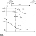
- Fig. 1 the curves of the speed of the two vehicles 1, 2 and the curve of the distance between the two vehicles 1, 2 are shown as examples.
- the variable dx corresponds to the minimum distance between the two vehicles 1, 2.
- the zero of the first derivative of the function dx (t) is sought, as given in equation (8).
- equation (9) leads to equation (10), with which the time t*, at which the minimum distance dx exists between the two vehicles 1, 2, is calculated.
- equation (12) results, which can be converted into equation (14) using equation (13).
- dx _ dx 0 + dv 0 t re act + a 1 2 t re act 2 + dv 0 + a 1 t re act ⁇ dv 0 + a 1 t re act ⁇ dv 0 + a 1 t re act ⁇ dv 0 + a 1 t re act ak a 1 ⁇ a 2 + a 1 ⁇ a 2 2 ⁇ dv 0 + a 1 t re act a 1 ⁇ a 2 2
- dx _ dx 0 + dv 0 t re act + a 1 a 2 t re act 2 + dv 0 + a 1 t re act ⁇ 1 dv 0 + a 1 t re act a 1 ⁇ a 2 + a 1 ⁇ a 2 2 dv 0 + a
- the minimum distance dx between the vehicles 1, 2 can be determined depending on the distance dx (0) between the vehicles 1, 2 at the current time, depending on the speed difference dv (0) between the vehicles 1, 2 at the time current time, depending on the accelerations a 1 , a 2 of the two vehicles 1, 2 and depending on the reaction time t reaction of the driver of the first vehicle 2 are calculated.
- the critical route is defined as the route on which the first vehicle 2 travels at a distance behind the second vehicle 1, which is below the minimum distance to the second vehicle 1, which is dependent on the speed v 2 (t) of the first vehicle 2.
- the immersion distance or the length of the critical travel distance therefore defines how long the first vehicle 2 immerses in the speed-dependent minimum distance from the second vehicle 1.
- the two times at which the first vehicle 2 enters the immersion distance and emerges from the immersion distance are calculated using the following equation (15) and then the immersion distance itself is calculated based on these two points in time.
- dx t T min ⁇ 2 t
- equation (18) results.
- c 1 : dx 0 + d ⁇ 0 t re act + a 1 2 t re act 2 s
- equation (21) can be converted into equation (22).
- c 3 : ⁇ dv 0 + a 1 t re act ⁇ a 2 T min v t ⁇ A
- Out of c 3 a 1 ⁇ a 2 ⁇ c 3 a 1 ⁇ a 2 2 ⁇ 2 c 1 ⁇ c 2 a 1 ⁇ a 2
- equation (23) can be converted into equation (25), which can be converted into equation (28) using equations (26) and (27).
- the immersion time and the emergence time can be expressed in terms of the constants c4 and c5 (see equations (G3) and (G4)) as given in equations (29) and (30).
- equation (28) can be transformed into equation (31).
- et ⁇ 2 0 c 4 + c 5 ⁇ c 4 + c 5 + a 2 2 2 c 4 c 5 + 2 c 4 c 5 + 2 t re act ⁇ 2 c 5
- equation (31) can finally be converted into equation (G1).
- Equation (G1) can be converted into the following equation (35), which can then be converted into the equation (36) and finally into the equation (37) based on the definition of the constant c5 according to the equation (G3).
- c 1 a 1 ⁇ a 2 2 c 4 2 ⁇ et 2 4 ⁇ 2 0 + a 2 c 4 + t re act 2 + c 2
- equation (37) can be converted into equation (G8).
- dx 0 a 1 ⁇ a 2 2 c 4 2 + et 2 4 ⁇ 2 0 + a 2 c 4 + t re act 2 + c 2 ⁇ dv 0 t re act ⁇ a 1 2 t re act 2
- dx(0) corresponds to a minimum vehicle distance between the first vehicle 2 and the second vehicle 1.
- This equation (38) can be converted into equation (39), which in turn can be converted into equation (40) using relationship (24), which in turn can be converted into equation (41) using equations (29) and (30). ) can be transferred.
- et ⁇ 2 0 t re act ⁇ t A + ⁇ 2 0 t Out of ⁇ t A + a 2 2 t Out of ⁇ t re act 2
- Equation (41) can finally be converted into equation (G2) via equation (42).
- et ⁇ 2 0 3 c 5 ⁇ c 4 + a 2 2 c 4 + c 5 2
- et 3 c 5 ⁇ c 4 ⁇ 2 0 + a 2 2 c 4 + c 5 2
- FIG. 4 the flowchart of an embodiment according to the invention for determining a vehicle condition is shown.
- the method comes to the second step S2, in which it is checked whether the speed-dependent minimum distance is immersed. This is the case, for example, if the radicand under the root in equation (21) or (22) is positive, i.e. if the radicand R according to the following equation (43) is greater than zero.
- R c 3 a 1 ⁇ a 2 2 ⁇ 2 c 1 ⁇ c 2 a 1 ⁇ a 2
- the vehicle condition is not determined to be critical and the procedure ends. If, on the other hand, the speed-dependent minimum distance is immersed (R > 0), the next step S3 checks whether the immersion distance is longer than a predetermined length threshold (i.e. a maximum permissible immersion distance). If this is the case, the vehicle condition is set to critical.
- a predetermined length threshold i.e. a maximum permissible immersion distance
- Fig. 5 the method according to the invention for determining the vehicle condition is shown schematically.
- the vehicle state is determined based on state variables Z of a current situation, such as a current distance dx (0) or Z, of the two vehicles 1, 2 and the current speeds Z 2 or v 1 (0), v 2 (0) of the two vehicles 1, 2, as measured using sensors, for example wheel sensors or lasers.
- the determination of the vehicle condition is parameterized by a parameter set P.
- This parameter set P includes the speed-independent minimum distance P 1 , the speed-dependent minimum distance P 2 , which z. B. is defined by the time gap T min , accelerations P3 or a 1 , a 2 of the two vehicles 1, 2, the reaction time P 4 or t react and the maximum permissible immersion distance P 5 or the predetermined length threshold value.
- an expected immersion distance 3 is calculated, which is compared with the maximum permissible immersion distance P5 by an evaluation 5.
- the result of this comparison is a binary criticality measure 11, ie the vehicle condition, which is classified as either critical or non-critical.
- This vehicle state 11 is fed to a lane change assistance system 13 of the vehicle either to issue a collision warning 12 for the vehicle and/or to assess whether the vehicle can change lanes.
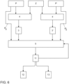
- Fig. 6 is a variant according to the invention of in Fig. 5 Determination of the vehicle condition shown is shown, in which the method is provided with a hysteresis in order to free the determination of the vehicle condition from possible jumpiness.
- Fig. 6 While at the in Fig. 6 The variant described has the same state variables Z as in Fig. 5 The provision shown in the figure below works Fig. 6 illustrated variant with two different parameter sets P, P'. As a result, despite the identical calculation method 4, two different expected immersion distances 3, 3' are calculated depending on the respective parameter set P or P'. These two expected immersion distances 3, 3' are each compared in the evaluation 5 with the associated maximum permissible immersion distance P5 , P'5 .
- the evaluation 5 now has a hysteresis. If the vehicle condition 11 has not yet been classified as critical, the evaluation 5 works with the expected immersion distance 3, which is determined by the normal parameter set P. However, if the vehicle condition 11 has been determined to be critical, the evaluation works with the expected immersion distance 3', which is determined by the other parameter set P'.
- the other parameter set P' is selected in comparison to the normal parameter set P in such a way that the vehicle state is always classified as critical by the other parameter set P' for the same state variables if it is classified as critical by the normal parameter set P.
- the vehicle 10 according to the invention which is supported by the present invention, is the first vehicle 2, which drives behind the second vehicle 1 on the same road.
- the driver of the vehicle 10 can in this case be warned accordingly against falling below the speed-dependent minimum distance for too long if the driver is approaching a slower vehicle 1 approaches in your own lane.
- the vehicle 10 according to the invention which is supported by the present invention, is the second vehicle 1 which wants to change to the adjacent lane of the first vehicle 2.
- the vehicle condition is determined based on the length of the critical route of the first vehicle 2, which is behind the vehicle 10 drives.
- This case is, for example, suitable for a lane change assistant of the vehicle 10 when a faster vehicle 2 approaches from behind in the adjacent lane to which the change is to be made.
- the vehicle state is also determined based on the length of the critical route of the first vehicle 2, which in this case is the vehicle 10 according to the invention.
- This case is, for example, suitable for a lane change assistant of the vehicle 10 when a slower vehicle 1 is driving ahead in the adjacent lane to which the change is to be made.
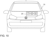
- a vehicle 10 according to the invention is shown schematically, which includes a device 20 according to the invention.
- the device 20 according to the invention in turn comprises, in addition to a controller 6, a sensor 7 and a warning device 8.
- the current distance dx(0) and the relative speed dv(0) between the vehicle 1 in front and the vehicle 2 following are recorded at a specific time.
- the two vehicles 1, 2 are in the same lane (see Fig. 7 ) or in adjacent lanes (see Fig. 8 or Fig. 9 ). Only if the distance dx(t) of the vehicles decreases (ie only if the relative speed dv(t) is negative) does the procedure continue.
- the distance covered in the submerged state i.e. the so-called immersion distance
- immersion distance a specified, maximum permissible immersion distance (e.g. 250 m). If the immersion distance is longer than the maximum permissible immersion distance, the vehicle condition is set to critical and otherwise is set to non-critical.
- the preceding vehicle 1 and the following vehicle 2 each accelerate or decelerate with a constant acceleration a 1 and a 2 , respectively.
- ACC Automatic Cruise Control
- the present invention can be used to assess whether the preceding vehicle 1 can merge in front of the following vehicle 2 without the following vehicle 2 having to slow down (excessively).
- the present invention can be used to issue a warning to the driver of the following vehicle 2, since if the vehicle 1 in front slows down significantly, he would have to decelerate fully in order not to collide and only temporarily fall below the speed-dependent distance.
Landscapes
- Engineering & Computer Science (AREA)
- Automation & Control Theory (AREA)
- Transportation (AREA)
- Mechanical Engineering (AREA)
- Physics & Mathematics (AREA)
- Mathematical Physics (AREA)
- Human Computer Interaction (AREA)
- Traffic Control Systems (AREA)
- Control Of Driving Devices And Active Controlling Of Vehicle (AREA)
Description
Die vorliegende Erfindung betrifft die Bestimmung eines kritischen Zustands eines Fahrzeugs.The present invention relates to determining a critical condition of a vehicle.
Die
Die
Die
Die
Die
Nach dem Stand der Technik existieren bereits warnende und eingreifende Systeme für Situationen bei einem Fahrzeug, in denen eine Kollision mit einem vorausfahrenden Fahrzeug droht. Daneben existieren allerdings auch Situationen, bei denen zwar keine Kollision droht, welche aber dennoch aufgrund einer drohenden Unterschreitung eines Sicherheitsabstands zu dem vorausfahrenden Fahrzeug als kritisch zu bewerten sind. Daher existiert ein auch im Verkehrsrecht bekannter geschwindigkeitsabhängiger Mindestabstand, welcher auch als "Tacho halbe" bekannt ist. Dabei wird eine Unterschreitung dieses geschwindigkeitsabhängigen Sicherheitsabstands nicht pauschal als kritisch angesehen. Eine entsprechend kurzfristige Unterschreitung des Sicherheitsabstands, wie sie häufig bei Fahrstreifenwechseln oder bei Annäherungen an ein vorausfahrendes Fahrzeug vorkommen, wird durch die Rechtsprechung toleriert und nicht sanktioniert. Erst wenn eine solche Unterschreitung des geschwindigkeitsabhängigen Mindestabstands bzw. Sicherheitsabstands eine vorbestimmte Schwelle übersteigt, wird sie laut geltender Verkehrsrechtsprechung sanktioniert.According to the state of the art, warning and intervention systems already exist for situations in a vehicle in which there is a risk of a collision with a vehicle in front. However, there are also situations in which there is no threat of collision, but which are still to be assessed as critical due to the risk of falling short of a safe distance from the vehicle in front. Therefore, there is a speed-dependent minimum distance, also known in traffic law, which is also known as “speedometer half”. If this is not achieved, this will depend on the speed Safety distance is not generally viewed as critical. Short-term shortfalls in the safety distance, as often occurs when changing lanes or when approaching a vehicle in front, are tolerated by jurisprudence and are not penalized. Only if such a failure to meet the speed-dependent minimum distance or safety distance exceeds a predetermined threshold will it be sanctioned according to applicable traffic law.
Daher stellt sich die vorliegende Erfindung die Aufgabe, dem Fahrer eines Fahrzeugs eine Information bereitzustellen, anhand welcher der Fahrer frühzeitig erkennt, ob eine solche Unterschreitung des geschwindigkeitsabhängigen Mindestabstands bzw. Sicherheitsabstands auftreten wird.The present invention therefore sets itself the task of providing the driver of a vehicle with information with which the driver can recognize at an early stage whether such a fall below the speed-dependent minimum distance or safety distance will occur.
Erfindungsgemäß wird diese Aufgabe durch ein Verfahren zum Bestimmen eines Fahrzeugzustands nach Anspruch 1 und 4em4 durch eine Vorrichtung zur Bestimmung eines Fahrzeugzustands nach Anspruch 5 gelöst. Die abhängigen Ansprüche definieren bevorzugte und vorteilhafte Ausführungsformen der vorliegenden Erfindung.According to the invention, this object is achieved by a method for determining a vehicle condition according to
Im Rahmen der vorliegenden Erfindung wird ein Verfahren zur Bestimmung eines Fahrzeugzustands, d.h. eines Zustands eines Fahrzeugs, bereitgestellt. Dabei umfasst das erfindungsgemäße Verfahren folgende Schritte:
- Bestimmen einer Länge einer kritischen Fahrstrecke eines ersten Fahrzeugs. Dabei ist die kritische Fahrstrecke als diejenige Fahrstrecke definiert, auf welcher das erste Fahrzeug einen von der Geschwindigkeit des ersten Fahrzeugs abhängigen Mindestabstand zu einem vor dem ersten Fahrzeug fahrenden zweiten Fahrzeug ständig unterschreitet.
- Bestimmen des Fahrzeugzustands als kritisch, wenn die Länge der kritischen Fahrstrecke größer als ein vorbestimmter Längenschwellenwert (d.h. eine vorbestimmte Länge) ist.
- Determining a length of a critical route of a first vehicle. The critical route is defined as the route on which the first vehicle constantly falls below a minimum distance, which is dependent on the speed of the first vehicle, to a second vehicle traveling in front of the first vehicle.
- Determining the vehicle condition as critical if the length of the critical route is greater than a predetermined length threshold (ie, a predetermined length).
Bei dem Fahrzeug, für welches der Fahrzeugzustand bestimmt wird, kann es sich dabei um das erste Fahrzeug oder um das zweite Fahrzeug handeln. Wenn es sich bei dem Fahrzeug, für welches der Fahrzeugzustand bestimmt wird, um das erste Fahrzeug handelt, wird quasi diejenige kritische Fahrstrecke bestimmt, auf welcher das (erste) Fahrzeug den geschwindigkeitsabhängigen Mindestabstand (genauer den von der Geschwindigkeit des (ersten) Fahrzeugs abhängigen Mindestabstand) ständig unterschreitet. Wenn es sich bei dem Fahrzeug, für welches der Fahrzeugzustand bestimmt wird, um das zweite Fahrzeug handelt, wird quasi diejenige kritische Fahrstrecke bestimmt, auf welcher das erste Fahrzeug seinen geschwindigkeitsabhängigen Mindestabstand (genauer den von der Geschwindigkeit des ersten Fahrzeugs abhängigen Mindestabstand) zu dem (zweiten) Fahrzeug ständig unterschreitet.The vehicle for which the vehicle state is determined can be the first vehicle or the second vehicle. If the vehicle for which the vehicle state is determined is the first vehicle, the critical route is determined, so to speak, on which the (first) vehicle reaches the speed-dependent minimum distance (more precisely, the minimum distance dependent on the speed of the (first) vehicle ) constantly falls below. If the vehicle for which the vehicle state is determined is the second vehicle, The critical route is determined, so to speak, on which the first vehicle constantly falls below its speed-dependent minimum distance (more precisely, the minimum distance dependent on the speed of the first vehicle) to the (second) vehicle.
Anhand des erfindungsgemäßen Verfahrens kann demnach bestimmt werden, wie lang die kritische Fahrstrecke ist, auf welcher der geschwindigkeitsabhängige Mindestabstand unterschritten wird. Wenn der vorbestimmte Längenschwellenwert gleich der von der ständigen Rechtsprechung aktuell angegebenen Streckenlänge von 250 m gesetzt wird, auf welcher der geschwindigkeitsabhängige Mindestabstand zum vorher fahrenden Fahrzeug unterschritten werden darf, ohne dass rechtliche Folgen für den Fahrzeugführer zu erwarten sind (siehe BGH NJW69, 939; OLG Köln VM 83 Nr. 80), wird der Fahrzeugzustand vorteilhafterweise erst dann als kritisch eingestuft, wenn das erste Fahrzeug länger als 250 m diesen geschwindigkeitsabhängigen Mindestabstand unterschreitet.The method according to the invention can therefore be used to determine how long the critical route is on which the speed-dependent minimum distance is undershot. If the predetermined length threshold value is set equal to the route length of 250 m currently specified by established case law, on which the speed-dependent minimum distance to the previous vehicle may be undershot without any legal consequences for the driver being expected (see BGH NJW69, 939; OLG Cologne VM 83 No. 80), the vehicle condition is advantageously only classified as critical when the first vehicle falls below this speed-dependent minimum distance for more than 250 m.
Die Länge der kritischen Fahrstrecke kann dabei abhängig von einem oder von mehreren Parametern bestimmt werden, welche aus der folgenden Parametergruppe ausgewählt werden:
- Die Beschleunigung des ersten Fahrzeugs. Dabei wird unter der Beschleunigung insbesondere eine negative konstante Beschleunigung verstanden, mit welcher die Geschwindigkeit des ersten Fahrzeugs verringert wird.
- Die Beschleunigung des zweiten Fahrzeugs. Dabei wird unter der Beschleunigung insbesondere eine negative konstante Beschleunigung verstanden, mit welcher die Geschwindigkeit des zweiten Fahrzeugs verringert wird.
- Die Reaktionszeit des Fahrers des ersten Fahrzeugs. Dabei wird unter der Reaktionszeit diejenige Zeit verstanden, welche verstreicht, bis das erste Fahrzeug mit der Beschleunigung des ersten Fahrzeugs beschleunigt bzw. abbremst.
- Eine Zeitlücke bzw. eine Zeitspanne, mit welcher der geschwindigkeitsabhängige Mindestabstand vor dem ersten Fahrzeug definiert wird.
- Die aktuelle Geschwindigkeit des ersten Fahrzeugs, d.h. die Geschwindigkeit des ersten Fahrzeugs zum aktuellen Zeitpunkt, zu dem der Fahrzeugzustand bestimmt wird.
- Die aktuelle Geschwindigkeit des zweiten Fahrzeugs, d.h. die Geschwindigkeit des zweiten Fahrzeugs zum aktuellen Zeitpunkt.
- Der aktuelle Abstand zwischen dem ersten Fahrzeug und dem zweiten Fahrzeug, d.h. der Abstand zwischen den Fahrzeugen zum aktuellen Zeitpunkt.
- The acceleration of the first vehicle. Acceleration is understood to mean, in particular, a negative constant acceleration with which the speed of the first vehicle is reduced.
- The acceleration of the second vehicle. Acceleration is understood to mean, in particular, a negative constant acceleration with which the speed of the second vehicle is reduced.
- The reaction time of the driver of the first vehicle. The reaction time is understood to be the time that elapses until the first vehicle accelerates or decelerates with the acceleration of the first vehicle.
- A time gap or a period of time with which the speed-dependent minimum distance in front of the first vehicle is defined.
- The current speed of the first vehicle, that is, the speed of the first vehicle at the current time at which the vehicle state is determined.
- The current speed of the second vehicle, that is, the speed of the second vehicle at the current time.
- The current distance between the first vehicle and the second vehicle, that is, the distance between the vehicles at the current time.
Anhand der vorab beschriebenen Parameter kann die Länge der kritischen Fahrstrecke bestimmt werden. Dabei können die aktuelle Geschwindigkeit des ersten Fahrzeugs, die aktuelle Geschwindigkeit des zweiten Fahrzeugs und der aktuelle Abstand zwischen dem ersten und dem zweiten Fahrzeug mit Hilfe von Sensoren desjenigen Fahrzeugs, für welches der Fahrzeugzustand zu bestimmen ist, erfasst werden.The length of the critical route can be determined using the parameters described above. The current speed of the first vehicle can be used current speed of the second vehicle and the current distance between the first and the second vehicle are recorded using sensors of the vehicle for which the vehicle state is to be determined.
Die Länge et der kritischen Fahrstrecke kann gemäß der folgenden Gleichung (G 1) berechnet werden, wenn das erste Fahrzeug die kritische Fahrstrecke nicht vor der Reaktionszeit tReakt erreicht, d.h. wenn das erste Fahrzeug den geschwindigkeitsabhängigen Mindestabstand erst nach Ablauf der Reaktionszeit unterschreitet, so dass das erste Fahrzeug bereits die entsprechende (in der Regel negative) Beschleunigung aufweist, wenn sich das erste Fahrzeug auf der kritischen Fahrstrecke befindet. In ähnlicher Weise kann die Länge et der kritischen Fahrstrecke gemäß der folgenden Gleichung (G 2) berechnet werden, wenn das erste Fahrzeug die kritische Fahrstrecke vor der Reaktionszeit erreicht, d.h. wenn das erste Fahrzeug den geschwindigkeitsabhängigen Mindestabstand bereits unterschreitet, wenn die Reaktionszeit abgelaufen ist, so dass das erste Fahrzeug den ersten Teil der kritischen Fahrstrecke ohne die entsprechende (in der Regel negative) Beschleunigung fährt. ![]()
![]()
![]()
![]()
Dabei definieren die folgenden Gleichungen (G 3) bis (G7) die Konstanten c1 bis c5. 
![]()
![]()
![]()
![]()
![]()
![]()
![]()
![]()
Dabei entspricht a1 der konstanten Beschleunigung des zweiten Fahrzeugs, a2 entspricht der konstanten Beschleunigung des ersten Fahrzeugs, tReakt der Reaktionszeit des Fahrers des ersten Fahrzeugs, Tmin der Zeitlücke bzw. Zeitspanne zur Berechnung des geschwindigkeitsabhängigen Mindestabstands zwischen den Fahrzeugen, dv(0) entspricht der aktuellen Geschwindigkeitsdifferenz zwischen den Fahrzeugen, und dx(0) entspricht dem aktuellen Abstand zwischen den Fahrzeugen. Der geschwindigkeitsabhängige Mindestabstand lässt sich insbesondere durch das Produkt aus der Zeitlücke Tmin und der Geschwindigkeit v2(t) des ersten Fahrzeugs berechnen.Here, a 1 corresponds to the constant acceleration of the second vehicle, a 2 corresponds to the constant acceleration of the first vehicle, t react is the reaction time of the driver of the first vehicle, T min is the time gap or time period for calculating the speed-dependent minimum distance between the vehicles, dv(0 ) corresponds to the current speed difference between the vehicles, and dx(0) corresponds to the current distance between the vehicles. The speed-dependent minimum distance can be calculated in particular by the product of the time gap T min and the speed v 2 (t) of the first vehicle.
Gemäß einer erfindungsgemäßen Ausführungsform kann die erfindungsgemäße Bestimmung des Fahrzeugzustands mit einer Hysterese versehen werden. Dazu wird für den Fall, dass der Fahrzeugzustand abhängig von einem Parametersatz als kritisch bestimmt worden ist, ein weiterer Fahrzeugzustand erfindungsgemäß mit einem weiteren Parametersatz bestimmt. Der Fahrzeugzustand wird nur dann auf nicht kritisch zurückgesetzt, wenn der weitere Fahrzeugzustand als nicht kritisch bestimmt wird. Dabei umfassen sowohl der Parametersatz als auch der weitere Parametersatz einen oder mehrere Parameter aus folgender Parametergruppe:
- Die Beschleunigung des ersten Fahrzeugs.
- Die Beschleunigung des zweiten Fahrzeugs.
- Die Reaktionszeit des Fahrers des ersten Fahrzeugs.
- Die Zeitlücke bzw. Zeitspanne Tmin zur Berechnung des geschwindigkeitsabhängigen Mindestabstands zwischen den Fahrzeugen.
- Der vorbestimmte Längenschwellenwert.
- The acceleration of the first vehicle.
- The acceleration of the second vehicle.
- The reaction time of the driver of the first vehicle.
- The time gap or time period T min for calculating the speed-dependent minimum distance between the vehicles.
- The predetermined length threshold.
Der Parametersatz wird im Vergleich zu dem weiteren Parametersatz so gewählt, dass unter gleichen Ausgangsbedingungen (z.B. gleichen Werten für v1(0), v2(0), dx(0)) der weitere Fahrzeugzustand erfindungsgemäß abhängig von dem weiteren Parametersatz immer als kritisch bestimmt wird, wenn der Fahrzeugzustand erfindungsgemäß abhängig von dem Parametersatz als kritisch bestimmt wird. Es ist also nicht möglich, dass der weitere Fahrzeugzustand erfindungsgemäß abhängig von dem weiteren Parametersatz als nicht kritisch bestimmt wird, wenn der Fahrzeugzustand erfindungsgemäß abhängig von dem Parametersatz unter den gleichen Ausgangsbedingungen als kritisch bestimmt worden ist. Dagegen ist es durchaus möglich, dass unter den gleichen Ausgangsbedingungen der weitere Fahrzeugzustand erfindungsgemäß abhängig von dem weiteren Parametersatz als kritisch bestimmt wird, während der Fahrzeugzustand erfindungsgemäß abhängig von dem Parametersatz nicht als kritisch bestimmt wird.The parameter set is selected in comparison to the further parameter set so that under the same initial conditions (e.g. same values for v 1 (0), v 2 (0), dx (0)) the further vehicle state is always considered critical according to the invention depending on the further parameter set is determined when the vehicle condition is determined as critical according to the invention depending on the parameter set. It is therefore not possible for the further vehicle state to be determined as non-critical according to the invention depending on the further parameter set if the vehicle state has been determined as critical according to the invention depending on the parameter set under the same initial conditions. On the other hand, it is entirely possible that, under the same initial conditions, the further vehicle state is determined as critical according to the invention depending on the further parameter set, while the vehicle state is not determined as critical according to the invention depending on the parameter set.
Durch die erfindungsgemäße Wahl des Parametersatz und des weiteren Parametersatzes wird die Bestimmung des Fahrzeugzustands mit der Hysterese versehen, wodurch vorteilhafterweise eine mögliche Sprunghaftigkeit bei der Bestimmung des Fahrzeugzustands, d.h. ein sprunghaftes Wechseln zwischen einem kritischen Fahrzeugzustand und einem unkritischen bzw. nicht kritischen Fahrzeugzustand, verhindert wird.By choosing the parameter set and the further parameter set according to the invention, the determination of the vehicle state is provided with the hysteresis, which advantageously prevents possible jumpiness in the determination of the vehicle state, ie a sudden change between a critical vehicle state and an uncritical or non-critical vehicle state .
Im Rahmen der vorliegenden Erfindung wird auch eine Vorrichtung zur Bestimmung eines Fahrzeugzustands bereitgestellt. Dabei umfasst die Vorrichtung einen oder mehrere Sensoren und eine Steuerung. Der oder die Sensoren sind in der Lage, einen aktuellen Abstand zwischen einem ersten Fahrzeug und einem vor dem ersten Fahrzeug fahrenden zweiten Fahrzeug, eine aktuelle Geschwindigkeit des ersten Fahrzeugs und eine aktuelle Geschwindigkeit des zweiten Fahrzeugs zu erfassen. Die Steuerung ist in der Lage, eine Länge der kritischen Fahrstrecke zu bestimmen und den Fahrzeugzustand als kritisch zu bestimmen, wenn diese Länge größer als der vorbestimmte Längenschwellenwert ist. Die kritische Fahrstrecke ist dabei so definiert, dass das auf der kritischen Fahrstrecke fahrende erste Fahrzeug auf der gesamten kritischen Fahrstrecke einen von der Geschwindigkeit des ersten Fahrzeugs abhängigen Mindestabstand zu dem zweiten Fahrzeug unterschreitet.Within the scope of the present invention, a device for determining a vehicle condition is also provided. The device includes one or more sensors and a controller. The sensor or sensors are able to detect a current distance between a first vehicle and a second vehicle traveling in front of the first vehicle, a current speed of the first vehicle and a current speed of the second vehicle. The controller is able to determine a length of the critical route and to determine the vehicle condition as critical if this length is greater than the predetermined length threshold. The critical route is defined in such a way that the first vehicle traveling on the critical route falls below a minimum distance to the second vehicle, which depends on the speed of the first vehicle, over the entire critical route.
Die Vorteile der erfindungsgemäßen Vorrichtung zur Bestimmung des Fahrzeugzustands entsprechen im Wesentlichen den Vorteilen des erfindungsgemäßen Verfahrens zum Bestimmen des Fahrzeugzustands, welche vorab im Detail ausgeführt sind, so dass hier auf eine Wiederholung verzichtet wird.The advantages of the device according to the invention for determining the vehicle condition essentially correspond to the advantages of the method according to the invention for determining the vehicle condition, which have been explained in detail in advance, so that repetition is omitted here.
Darüber hinaus ist die erfindungsgemäße Vorrichtung zur Bestimmung des Fahrzeugzustands, insbesondere zur Durchführung aller vorab beschriebenen Ausführungsformen des Verfahrens zum Bestimmen des Fahrzeugzustands, und/oder zur Unterstützung eines Fahrers beim Führen eines Fahrzeugs, insbesondere zur Durchführung aller vorab beschriebenen Ausführungsformen des Verfahrens zur Unterstützung eines Fahrers beim Führen eines Fahrzeugs, ausgestaltet.In addition, the device according to the invention is for determining the vehicle condition, in particular for carrying out all previously described embodiments of the method for determining the vehicle condition, and / or for supporting a driver when driving a vehicle, in particular for carrying out all previously described embodiments of the method for supporting a driver when driving a vehicle.
Schließlich kann im Rahmen der vorliegenden Erfindung ein Fahrzeug bereitgestellt werden, welches eine erfindungsgemäße Vorrichtung zur Bestimmung des Fahrzeugzustands umfasst.Finally, within the scope of the present invention, a vehicle can be provided which comprises a device according to the invention for determining the vehicle condition.
Es sei explizit darauf hingewiesen, dass bei allen erfindungsgemäßen Ausführungsformen das erste und das zweite Fahrzeug in derselben, aber auch in verschiedenen oder benachbarten Fahrspuren fahren können oder die Fahrspuren wechseln können, während beispielsweise das erste Fahrzeug die kritische Fahrstrecke befährt.It should be explicitly pointed out that in all embodiments according to the invention, the first and second vehicles can drive in the same lane, but also in different or adjacent lanes, or can change lanes while, for example, the first vehicle is traveling on the critical route.
Im Vergleich zum Stand der Technik können durch die vorliegende Erfindung auch Situationen als kritisch eingestuft werden, welche zwar nicht zu einer Kollision führen, aber rechtliche Konsequenzen aufgrund des Unterschreitens des geschwindigkeitsabhängigen Mindestabstands und/oder des geschwindigkeitsunabhängigen Mindestabstands mit sich bringen können.In comparison to the prior art, the present invention can also classify situations as critical which do not lead to a collision, but do lead to a legal one can have consequences due to falling below the speed-dependent minimum distance and/or the speed-independent minimum distance.
Die vorliegende Erfindung ist insbesondere für Kraftfahrzeuge mit einem Fahrerassistenzsystem zur Unterstützung des Fahrers geeignet. Selbstverständlich ist die vorliegende Erfindung nicht auf diesen bevorzugten Anwendungsbereich eingeschränkt, da die vorliegende Erfindung beispielsweise auch bei Schiffen oder Flugzeugen sowie gleisgebundenen oder spurgeführten Fahrzeugen einsetzbar ist.The present invention is particularly suitable for motor vehicles with a driver assistance system to support the driver. Of course, the present invention is not limited to this preferred area of application, since the present invention can also be used, for example, in ships or aircraft as well as track-bound or track-guided vehicles.
Im Folgenden wird die vorliegende Erfindung anhand bevorzugter erfindungsgemäßer Ausführungsformen mit Bezug zu den Figuren im Detail beschrieben.
- In
Fig. 1 ist schematisch der Verlauf der Geschwindigkeiten und der Entfernung bezüglich eines ersten und eines vor diesem fahrenden zweiten Fahrzeugs über der Zeit dargestellt. - In
Fig. 2 sind schematisch die inFig. 1 dargestellten Verläufe ergänzt um eine Eintauchstrecke dargestellt, wobei das erste Fahrzeug nach der Reaktionszeit in die Eintauchstrecke eintaucht. - In
Fig. 3 sind schematisch die inFig. 1 dargestellten Verläufe ergänzt um eine Eintauchstrecke dargestellt, wobei das erste Fahrzeug vor der Reaktionszeit in die Eintauchstrecke eintaucht. - In
Fig. 4 ist der Flussplan einer erfindungsgemäßen Ausführungsform zur Bestimmung eines Fahrzeugzustands dargestellt. - In
Fig. 5 ist schematisch in Form eines Blockdiagramms dargestellt, wie erfindungsgemäß der Fahrzeugzustand ohne Hysterese bestimmt wird. - In
Fig. 6 ist schematisch in Form eines Blockdiagramms dargestellt, wie erfindungsgemäß der Fahrzeugzustand mit Hysterese bestimmt wird. - In
Figuren 7 bis 9 - In
Fig. 10 ist ein erfindungsgemäßes Fahrzeug mit einer erfindungsgemäßen Vorrichtung schematisch dargestellt.
- In
Fig. 1 The course of the speeds and the distance relative to a first vehicle and a second vehicle traveling in front of it is shown schematically over time. - In
Fig. 2 are schematically the inFig. 1 The courses shown are supplemented by an immersion route, with the first vehicle entering the immersion route after the reaction time. - In
Fig. 3 are schematically the inFig. 1 The courses shown are supplemented by an immersion route, with the first vehicle entering the immersion route before the reaction time. - In
Fig. 4 the flowchart of an embodiment according to the invention for determining a vehicle condition is shown. - In
Fig. 5 is shown schematically in the form of a block diagram of how the vehicle state is determined according to the invention without hysteresis. - In
Fig. 6 is shown schematically in the form of a block diagram of how the vehicle state is determined using hysteresis according to the invention. - In
Figures 7 to 9 Three different traffic situations are shown in which the present invention can be used. - In
Fig. 10 A vehicle according to the invention with a device according to the invention is shown schematically.
Im Folgenden werden die Gleichungen zur Berechnung einer Länge einer kritischen Fahrstrecke und zur Berechnung einer Fahrzeugmindestentfernung hergeleitet. ![]()
![]()
![]()
![]()
![]()
![]()
Anhand der vorab stehenden Gleichungen (1) und (2) kann der Verlauf der Geschwindigkeit v2(t) des ersten Fahrzeugs über der Zeit abhängig von der aktuellen Geschwindigkeit v2(0) des ersten Fahrzeugs, von der konstanten (in der Regel negativen) Beschleunigung a2 des ersten Fahrzeugs und von der Reaktionszeit tReakt des Fahrers des ersten Fahrzeugs bestimmt werden. In ähnlicher Weise kann anhand der vorab stehenden Gleichung (3) der Verlauf der Geschwindigkeit v1(t) des zweiten Fahrzeugs über der Zeit abhängig von der aktuellen Geschwindigkeit v1(0) des zweiten Fahrzeugs und von der konstanten (in der Regel negativen) Beschleunigung a1 des zweiten Fahrzeugs bestimmt werden.Using the equations (1) and (2) above, the course of the speed v 2 (t) of the first vehicle over time can be determined depending on the current speed v 2 (0) of the first vehicle, from the constant (usually negative ) Acceleration a 2 of the first vehicle and the reaction time t reaction of the driver of the first vehicle are determined. In a similar way, using equation (3) above, the course of the speed v 1 (t) of the second vehicle over time can be determined depending on the current speed v 1 (0) of the second vehicle and on the constant (usually negative) Acceleration a 1 of the second vehicle can be determined.
Die folgenden Gleichungen (4) und (5) geben die Differenzgeschwindigkeit zwischen dem ersten Fahrzeug und dem zweiten Fahrzeug über der Zeit an. Dabei entspricht dv(0) der Differenzgeschwindigkeit zwischen den beiden Fahrzeugen zum aktuellen Zeitpunkt. ![]()
![]()
![]()
![]()
Die beiden folgenden Gleichungen (6) und (7) geben den Abstand zwischen dem ersten Fahrzeug und dem zweiten Fahrzeug über der Zeit an. Dabei entspricht dx(0) dem Abstand zwischen den beiden Fahrzeugen zum aktuellen Zeitpunkt. ![]()

![]()
In ![]()
![]()
Ausgehend von Gleichung (8) kommt man über die Gleichung (9) zur Gleichung (10), mit welcher der Zeitpunkt t*, zu welchem der minimale Abstand dx zwischen den beiden Fahrzeugen 1, 2 vorliegt, berechnet wird. ![]()
![]()
![]()
![]()
Mit Kenntnis des Zeitpunkts t* kann dann anhand der Gleichung (11) der minimale Abstand dx bestimmt werden. ![]()
![]()
Setzt man den Wert für t* aus Gleichung (10) in Gleichung (7) ein, ergibt sich folgende Gleichung (12), welche über Gleichung (13) in Gleichung (14) umgeformt werden kann. 

![]()
![]()
Mit der Gleichung (14) kann der minimale Abstand dx zwischen den Fahrzeugen 1, 2 abhängig von dem Abstand dx(0) zwischen den Fahrzeugen 1, 2 zum aktuellen Zeitpunkt, abhängig von der Geschwindigkeitsdifferenz dv(0) zwischen den Fahrzeugen 1, 2 zum aktuellen Zeitpunkt, abhängig von den Beschleunigungen a1, a2 der beiden Fahrzeuge 1, 2 und abhängig von der Reaktionszeit tReakt des Fahrers des ersten Fahrzeugs 2 berechnet werden.With equation (14), the minimum distance dx between the
Im Folgenden wird eine Eintauchstrecke, welche der Länge der kritischen Fahrstrecke entspricht, berechnet. Die kritische Fahrstrecke ist dabei als diejenige Fahrstrecke definiert, auf welcher das erste Fahrzeug 2 mit einem Abstand hinter dem zweiten Fahrzeug 1 herfährt, welcher unterhalb des von der Geschwindigkeit v2(t) des ersten Fahrzeugs 2 abhängigen Mindestabstands zum zweiten Fahrzeug 1 liegt. Die Eintauchstrecke bzw. die Länge der kritischen Fahrstrecke definiert demnach, wie lang das erste Fahrzeug 2 in den geschwindigkeitsabhängigen Mindestabstand zum zweiten Fahrzeug 1 eintaucht. Zur Berechnung der Eintauchstrecke werden die beiden Zeitpunkte, zu welchen das erste Fahrzeug 2 in die Eintauchstrecke eintaucht und aus der Eintauchstrecke austaucht, durch folgende Gleichung (15) berechnet und dann ausgehend von diesen beiden Zeitpunkten die Eintauchstrecke selbst berechnet. ![]()
![]()
Unter der Annahme, dass der Eintauchzeitpunkt erst nach Ablauf der Reaktionszeit vorliegt, ergibt sich anhand der Gleichungen (2) und (7) (t > tReakt) die folgende Gleichung (16). 
Mit den folgenden Konstanten c1 und c2 gemäß der Gleichungen (G6) und (G7) sowie der neu eingeführten Variablen t̃ gemäß Gleichung (17) ergibt sich Gleichung (18). ![]()
![]()
![]()
![]()
![]()
![]()
![]()
![]()
Über die in Gleichungen (19) und (20) angegebenen Umformung ergibt sich schließlich die Gleichung (21) zur Bestimmung des Eintauch-Zeitpunkts t̃Ein und des Austauch-Zeitpunkts t̃Aus. The transformation specified in equations (19) and (20) ultimately results in equation (21) for determining the immersion time t̃ in and the emergence time t̃ out .
Dabei gilt das Minuszeichen vor der Wurzel für den Eintauch-Zeitpunkt t̃Ein und das Pluszeichen für den Austauch-Zeitpunkt t̃Aus . ![]()


![]()
Mit der Konstanten c3 gemäß der Gleichung (G5) kann die Gleichung (21) in die Gleichung (22) überführt werden. ![]()

![]()
Die Eintauchstrecke et kann nun anhand der Gleichung (23) berechnet werden. ![]()
![]()
Über die Beziehung (24) kann die Gleichung (23) in die Gleichung (25) überführt werden, welche über die Gleichungen (26) und (27) in die Gleichung (28) umgeformt werden kann. ![]()
![]()
![]()
![]()
![]()
![]()
![]()
![]()
![]()
![]()
Der Eintauch-Zeitpunkt und der Austauch-Zeitpunkt können anhand der Konstanten c4 und c5 (siehe Gleichungen (G3) und (G4)) ausgedrückt werden, wie es in Gleichungen (29) und (30) angegeben ist. ![]()

![]()
![]()
![]()
![]()
![]()
Anhand der Gleichungen (29) und (30) kann die Gleichung (28) in die Gleichung (31) umgeformt werden. ![]()
![]()
Anhand der in den Gleichungen (32) bis (34) angegebenen Umformungen, kann die Gleichung (31) schließlich in die Gleichung (G1) überführt werden ![]()
![]()
![]()
![]()
![]()
![]()
![]()
![]()
Die Gleichung (G1) kann in folgende Gleichung (35) überführt werden, welche dann anhand der Definition der Konstante c5 gemäß der Gleichung (G3) in die Gleichung (36) und schließlich in die Gleichung (37) überführt werden kann. 
![]()

![]()
Anhand der Definition der Konstante c1 gemäß Gleichung (G7) kann die Gleichung (37) in die Gleichung (G8) überführt werden. 
dx(0) entspricht gemäß Gleichung (G8) einer Fahrzeugmindestentfernung zwischen dem ersten Fahrzeug 2 und dem zweiten Fahrzeug 1. Diese Fahrzeugmindestentfernung muss zum aktuellen Zeitpunkt (t=0) mindestens vorliegen, damit bei einer um die Reaktionszeit tReakt verzögerten Beschleunigung bzw. Verzögerung a2 des ersten Fahrzeugs 2 als Reaktion auf eine Beschleunigung bzw. Verzögerung a1 des vorausfahrenden zweiten Fahrzeugs 1 das erste Fahrzeug 2 den geschwindigkeitsabhängigen Sicherheitsabstand, welcher mittels der Zeitlücke Tmin bestimmt wird, nur über eine Strecke von höchstens der Länge et unterschreitet.According to equation (G8), dx(0) corresponds to a minimum vehicle distance between the
Mit Hilfe der in 
Diese Gleichung (38) kann in die Gleichung (39) überführt werden, welche wiederum anhand der Beziehung (24) in die Gleichung (40) überführt werden kann, welche wiederum anhand der Gleichungen (29) und (30) in die Gleichung (41) überführt werden kann. ![]()
![]()
![]()
![]()
![]()
![]()
Die Gleichung (41) kann schließlich über die Gleichung (42) in die Gleichung (G2) überführt werden. ![]()
![]()
![]()
![]()
In
Im ersten Schritt S1 wird beispielsweise anhand der vorab stehenden Gleichung (14) überprüft, ob ein von der Geschwindigkeit des ersten Fahrzeugs 2 unabhängiger Mindestabstand (z.B. 10 m) eingehalten wird. Wenn dies nicht der Fall ist, wird der Fahrzeugzustand auf kritisch gesetzt. Wenn der geschwindigkeitsunabhängige Mindestabstand eingehalten wird, kommt das Verfahren zum zweiten Schritt S2, in welchem überprüft wird, ob in den geschwindigkeitsabhängigen Mindestabstand eingetaucht wird. Dies ist beispielsweise der Fall, wenn der Radikand unter der Wurzel in Gleichung (21) oder (22) positiv ist, wenn also der Radikand R gemäß der folgenden Gleichung (43) größer als Null ist. 
Wenn nicht in den geschwindigkeitsabhängigen Mindestabstand eingetaucht wird (R ≤ 0), wird der Fahrzeugzustand nicht als kritisch bestimmt und das Verfahren endet. Wenn dagegen in den geschwindigkeitsabhängigen Mindestabstand eingetaucht wird (R > 0), wird im nächsten Schritt S3 überprüft, ob die Eintauchstrecke länger als ein vorbestimmter Längenschwellenwert (d.h. eine höchstzulässige Eintauchstrecke) ist. Falls dies der Fall ist, wird der Fahrzeugzustand auf kritisch gesetzt.If the speed-dependent minimum distance is not entered (R ≤ 0), the vehicle condition is not determined to be critical and the procedure ends. If, on the other hand, the speed-dependent minimum distance is immersed (R > 0), the next step S3 checks whether the immersion distance is longer than a predetermined length threshold (i.e. a maximum permissible immersion distance). If this is the case, the vehicle condition is set to critical.
In
Die Bestimmung des Fahrzeugzustands erfolgt ausgehend von Zustandsgrößen Z einer aktuellen Situation, wie einem aktuellen Abstand dx(0) bzw. Z, der beiden Fahrzeuge 1, 2 sowie den aktuellen Geschwindigkeiten Z2 bzw. v1(0), v2(0) der beiden Fahrzeuge 1, 2, wie sie anhand von Sensoren, beispielsweise Radsensoren oder Lasern, gemessen werden. Daneben wird die Bestimmung des Fahrzeugzustands durch einen Parametersatz P parametriert. Dieser Parametersatz P umfasst den geschwindigkeitsunabhängigen Mindestabstand P1, den geschwindigkeitsabhängigen Mindestabstand P2, welcher z. B. durch die Zeitlücke Tmin definiert wird, Beschleunigungen P3 bzw. a1, a2 der beiden Fahrzeuge 1, 2, die Reaktionszeit P4 bzw. tReakt und die höchstzulässige Eintauchstrecke P5 bzw. den vorbestimmten Längenschwellenwert. Anhand einer Berechnung 4 wird eine erwartete Eintauchstrecke 3 berechnet, welche durch eine Auswertung 5 mit der höchstzulässigen Eintauchstrecke P5 verglichen wird. Das Ergebnis dieses Vergleichs ist ein binäres Kritikalitätsmaß 11, d.h. der Fahrzeugzustand, welche entweder als kritisch oder als nicht kritisch eingestuft wird. Dieser Fahrzeugzustand 11 wird entweder zur Ausgabe einer Auffahrwarnung 12 für das Fahrzeug und/oder zur Beurteilung einer Spurwechselmöglichkeit des Fahrzeugs einem Spurwechselassistenzsystem 13 des Fahrzeugs zugeführt.The vehicle state is determined based on state variables Z of a current situation, such as a current distance dx (0) or Z, of the two
In
Während bei der in
Dabei weist die Auswertung 5 nun eine Hysterese auf. Wenn der Fahrzeugzustand 11 bisher als nicht kritisch eingestuft wird, arbeitet die Auswertung 5 mit der erwarteten Eintauchstrecke 3, welche durch den normalen Parametersatz P bestimmt wird. Wenn der Fahrzeugzustand 11 allerdings als kritisch bestimmt wurde, arbeitet die Auswertung mit der erwarteten Eintauchstrecke 3', welche durch den anderen Parametersatz P' bestimmt wird. Dabei ist der andere Parametersatz P' im Vergleich zu dem normalen Parametersatz P derart gewählt, dass der Fahrzeugzustand bei denselben Zustandsgrößen durch den anderen Parametersatz P' immer als kritisch eingestuft wird, wenn er durch den normalen Parametersatz P als kritisch eingestuft wird. Dagegen kann der Fall auftreten, dass der Fahrzeugzustand bei denselben Zustandsgrößen durch den anderen Parametersatz P' als kritisch eingestuft wird, während der Fahrzeugzustand durch den normalen Parametersatz P als nicht kritisch bestimmt wird. Damit ist vorteilhafterweise sichergestellt, dass der Fahrzeugzustand nur dann von kritisch auf unkritisch zurückgesetzt wird, wenn sich die Zustandsgrößen merklich verbessert haben.The
In
In
In
Dagegen handelt es sich in
In
Anhand der erfindungsgemäßen Vorrichtung 20 soll nochmals ein erfindungsgemäßes Vorgehen im Detail erläutert werden.Using the
Mit Hilfe des Sensors 7 wird zu einem bestimmten Zeitpunkt der aktuelle Abstand dx(0) und die Relativgeschwindigkeit dv(0) zwischen dem vorausfahrenden Fahrzeug 1 und dem folgenden Fahrzeug 2 erfasst. Die beiden Fahrzeuge 1, 2 befinden sich auf derselben Fahrspur (siehe
Es wird überprüft, ob im zeitlichen Verlauf der geschwindigkeitsunabhängige Mindestabstand zwischen den Fahrzeugen 1, 2 unterschritten wird. Wenn der ermittelte minimale Abstand dx zwischen den beiden Fahrzeugen 1, 2 unterhalb des geforderten geschwindigkeitsunabhängigen Mindestabstands liegt, wird der Fahrzeugzustand auf kritisch gesetzt. Das Vorgehen wird fortgeführt, wenn der Fahrzeugzustand bisher nicht als kritisch bestimmt wurde.It is checked whether the speed-independent minimum distance between
Es wird überprüft, ob im zeitlichen Verlauf der geschwindigkeitsabhängige Mindestabstand zwischen den Fahrzeugen 1, 2 irgendwann unterschritten wird. Wenn dies nicht der Fall ist, wird der Fahrzeugzustand auf nicht kritisch gesetzt. Nur im anderen Fall wird das Vorgehen fortgeführt.It is checked whether the speed-dependent minimum distance between
Die im eingetauchten Zustand zurückgelegte Strecke (d.h. die so genannte Eintauchstrecke) wird bestimmt und mit einer vorgegebenen, höchstzulässigen Eintauchstrecke (z.B. 250 m) verglichen. Wenn die Eintauchstrecke länger als die höchstzulässige Eintauchstrecke ist, wird der Fahrzeugzustand auf kritisch gesetzt und sonst auf nicht kritisch gesetzt.The distance covered in the submerged state (i.e. the so-called immersion distance) is determined and compared with a specified, maximum permissible immersion distance (e.g. 250 m). If the immersion distance is longer than the maximum permissible immersion distance, the vehicle condition is set to critical and otherwise is set to non-critical.
Bei der Bestimmung der Eintauchstrecke wird insbesondere angenommen, dass das vorausfahrende Fahrzeug 1 und das folgende Fahrzeug 2 jeweils mit einer konstanten Beschleunigung a1 bzw. a2 beschleunigen bzw. verzögern. Beispielsweise kann die Beschleunigung des vorausfahrenden Fahrzeugs a1 = -1 m/s2 und die Beschleunigung des nachfolgenden Fahrzeugs 2 kann a2 = -3,5 m/s2 betragen. D.h. das vorausfahrende Fahrzeug 1 verzögert leicht und das nachfolgende Fahrzeug 2 verzögert mit seiner maximalen ACC-Verzögerung (ACC, "Automatic Cruise Control"), so dass durch die vorliegende Erfindung eine frühe Auffahrwarnung für ein mittels ACC geregeltes Fahrzeug realisiert werden kann.When determining the immersion distance, it is assumed in particular that the preceding
Bei einem anderen Beispiel beträgt a1 = 0 m/s2 (d.h. das vorausfahrende Fahrzeug 1 beschleunigt und bremst nicht) und a2 = -2 m/s2 (d.h. das nachfolgende Fahrzeug 2 verzögert moderat). In diesem Fall kann durch die vorliegende Erfindung eine Beurteilung erfolgen, ob das vorausfahrende Fahrzeug 1 vor das nachfolgende Fahrzeug 2 einfädeln kann, ohne dass das nachfolgende Fahrzeug 2 (über Gebühr) verzögern müsste.In another example, a 1 = 0 m/s 2 (ie the
Bei einem anderen Beispiel beträgt a1 = -5 m/s2 (d.h. das vorausfahrende Fahrzeug 1 verzögert stark) und a2 = -8 m/s2 (d.h. das nachfolgende Fahrzeug verzögert beinah maximal). In diesem Fall kann durch die vorliegende Erfindung eine Warnung an den Fahrer des folgenden Fahrzeugs 2 ausgegeben werden, da dieser bei deutlicher Verzögerung des vorausfahrenden Fahrzeugs 1 voll verzögern müsste, um nicht zu kollidieren und den geschwindigkeitsabhängigen Abstand nur vorübergehend zu unterschreiten.In another example, a 1 = -5 m/s 2 (ie the
- 11
- vorher-fahrendes Fahrzeugprevious vehicle
- 22
- nach-fahrendes Fahrzeugfollowing vehicle
- 3, 3'3, 3'
- EintauchstreckeImmersion distance
- 44
- Berechnungcalculation
- 55
- AuswertungEvaluation
- 66
- Steuerungsteering
- 77
- Sensorsensor
- 88th
- WarneinrichtungWarning device
- 1010
- Ego-FahrzeugEgo vehicle
- 1111
- Kritikalitätsmaß bzw. kritischer oder unkritischer Zustand des FahrzeugsCriticality measure or critical or non-critical state of the vehicle
- 1212
- AuffahrwarnungCollision warning
- 1313
- SpurwechselassistenzsystemLane change assistance system
- a1a1
- Beschleunigung des ersten FahrzeugsAcceleration of the first vehicle
- a2a2
- Beschleunigung des zweiten FahrzeugsAcceleration of the second vehicle
- dxdx
- Abstand zwischen erstem und zweitem FahrzeugDistance between first and second vehicle
- P*P*
- Parameterparameter
- P, P'P, P'
- ParametersatzParameter set
- P5, P'5P5, P'5
- höchstzulässige Eintauchstreckemaximum permissible immersion distance
- S1-S3S1-S3
- VerfahrensschrittProcedural step
- tt
- ZeitTime
- tEintA
- Zeitpunkt, zu dem der geschwindigkeitsabhängige Mindestabstand erstmals unterschritten wirdTime at which the speed-dependent minimum distance is exceeded for the first time
- tAustOff
- Zeitpunkt, zu dem der geschwindigkeitsabhängige Mindestabstand erstmals nicht mehr unterschritten wirdTime at which the speed-dependent minimum distance is no longer undercut for the first time
- tReakttReact
- Reaktionszeitreaction time
- TminTmin
- Zeitlücke zur Berechnung des geschwindigkeitsabhängigen MindestabstandsTime gap for calculating the speed-dependent minimum distance
- v1v1
- Geschwindigkeit des ersten FahrzeugsSpeed of the first vehicle
- v2v2
- Geschwindigkeit des zweiten FahrzeugsSpeed of the second vehicle
- Z*Z*
- Zustand bzw. Zustandsgröße des FahrzeugsCondition or condition variable of the vehicle
Claims (6)
- Method for determining a vehicle state (11) by means of an apparatus (20) comprising sensor means (7) and control means (6), wherein the method comprises the following steps of:using the sensor means (7) to capture a current distance (dx(0)) between a first vehicle (2) and a second vehicle (1) driving in front of the first vehicle (2), a current speed (v2(0)) of the first vehicle (2) and a current speed (v2(0)) of the second vehicle (1),using the control means (6) to determine a length of a critical route of a first vehicle (2), wherein the critical route is defined such that the first vehicle (2) driving on the critical route undershoots a minimum distance from a second vehicle (1) driving in front of the first vehicle (2), which minimum distance is dependent on a speed (v2) of the first vehicle (2), only on the entire critical route,using the control means (6) to determine the vehicle state (11) as critical when the length is longer than a predetermined length threshold value (P5; P'5).
- Method according to Claim 1,
characterizedin that the length of the critical route is determined on the basis of at least one parameter from a group of parameters, andin that the group of parameters comprises:• an acceleration (a1) of the second vehicle (1),• an acceleration (a2) of the first vehicle (2),• a response time (tReakt) of a driver of the first vehicle (2),• a current speed (v1(0)) of the second vehicle (1),• a period of time (Tmin) for calculating the speed-dependent minimum distance between the vehicles (1, 2),• a current speed (v2(0)) of the first vehicle (2), and• a current distance (dx(0)) between the first vehicle (2) and the second vehicle (1). - Method according to Claim 2,
characterizedin that the length et of the critical route is calculated according to the following equation (G1) when the first vehicle (2) does not reach the critical route before the response time tReakt in that the length et of the critical route is calculated according to the following equation (G2) when the first vehicle (2) reaches the critical route before the response time tReakt
 where
where


 where a2 is the acceleration of the second vehicle (1), a2 is the acceleration of the first vehicle (2), tReakt is the response time of the driver of the first vehicle (2), Tmin is a period of time for calculating the speed-dependent minimum distance, dv(0) is a current speed difference between the speed v2(0) of the first vehicle (2) and the speed v1(0) of the second vehicle (1), and dx(0) is a current distance between the first vehicle (2) and the second vehicle (1).
 - Method according to one of the preceding claims,
characterizedin that, if the vehicle state (11) has been determined as critical on the basis of a parameter set (P), a further vehicle state is determined using the method according to one of the preceding claims on the basis of a further parameter set (P'),in that the parameter set (P) and the further parameter set (P') comprise at least one parameter from a further group of parameters, wherein the further group of parameters comprises:• an acceleration (a2) of the second vehicle (1),• an acceleration (a2) of the first vehicle (2), and• a response time (tReakt) of a driver of the first vehicle (2),• a period of time (Tmin) for calculating the speed-dependent minimum distance between the vehicles (1, 2), and• the predetermined length threshold value,in that the parameter set (P) is selected, in comparison with the further parameter set (P'), in such a manner that, under the same starting conditions, the further vehicle state is always determined as critical by the method according to one of the preceding claims on the basis of the further parameter set (P') when the vehicle state is likewise determined as critical by the method according to one of the preceding claims on the basis of the parameter set (P), andin that the vehicle state (11) is only reset to noncritical when the further vehicle state is not determined as critical. - Apparatus for determining a vehicle state,wherein the apparatus (20) comprises sensor means (7) and control means (6),wherein the sensor means (7) are configured to capture a current distance (dx(0)) between a first vehicle (2) and a second vehicle (1) driving in front of the first vehicle (2), a current speed (v2(0)) of the first vehicle (2) and a current speed (v1(0)) of the second vehicle (1),wherein the control means (6) are configured to determine a length of a critical route, wherein the critical route is defined such that the first vehicle (2) driving on the critical route undershoots a minimum distance from the second vehicle (1), which minimum distance is dependent on the speed (v2) of the first vehicle (2), only on the entire critical route, andwherein the control means are configured to determine the vehicle state as critical when the length is longer than a predetermined length threshold value (P5; P'5).
- Apparatus according to Claim 5,
characterized
in that the apparatus (20) is configured to carry out the method according to one of Claims 2 to 4.
Applications Claiming Priority (2)
| Application Number | Priority Date | Filing Date | Title |
|---|---|---|---|
| DE102014210174.3A DE102014210174B4 (en) | 2014-05-28 | 2014-05-28 | Determining a critical vehicle condition and a minimum vehicle distance |
| PCT/EP2015/057357 WO2015180876A1 (en) | 2014-05-28 | 2015-04-02 | Determining a critical vehicle state and a vehicle minimum distance |
Publications (2)
| Publication Number | Publication Date |
|---|---|
| EP3148855A1 EP3148855A1 (en) | 2017-04-05 |
| EP3148855B1 true EP3148855B1 (en) | 2023-11-01 |
Family
ID=52998104
Family Applications (1)
| Application Number | Title | Priority Date | Filing Date |
|---|---|---|---|
| EP15718152.0A Active EP3148855B1 (en) | 2014-05-28 | 2015-04-02 | Determining a critical vehicle state |
Country Status (4)
| Country | Link |
|---|---|
| EP (1) | EP3148855B1 (en) |
| CN (1) | CN106414204B (en) |
| DE (1) | DE102014210174B4 (en) |
| WO (1) | WO2015180876A1 (en) |
Families Citing this family (6)
| Publication number | Priority date | Publication date | Assignee | Title |
|---|---|---|---|---|
| DE102014215980A1 (en) | 2014-08-12 | 2016-02-18 | Volkswagen Aktiengesellschaft | Motor vehicle with cooperative autonomous driving mode |
| JP6613509B2 (en) * | 2017-12-21 | 2019-12-04 | 本田技研工業株式会社 | Vehicle control device, vehicle control method, and program |
| US20190315361A1 (en) * | 2018-04-11 | 2019-10-17 | Hyundai Motor Company | Apparatus and method for controlling lane change in vehicle |
| CN108791366B (en) * | 2018-05-31 | 2020-02-14 | 北京全路通信信号研究设计院集团有限公司 | Multi-train cooperative control method and system adopting virtual coupling |
| CN108806331B (en) * | 2018-06-22 | 2021-02-02 | 安徽科力信息产业有限责任公司 | Method and system for preventing secondary traffic accidents on highway |
| CN109300323A (en) * | 2018-11-21 | 2019-02-01 | 荆门博谦信息科技有限公司 | A kind of speed bootstrap technique and system based on car networking |
Citations (1)
| Publication number | Priority date | Publication date | Assignee | Title |
|---|---|---|---|---|
| EP2388160B1 (en) * | 2010-05-17 | 2012-10-31 | Volvo Car Corporation | Motor vehicle distance information system and method |
Family Cites Families (10)
| Publication number | Priority date | Publication date | Assignee | Title |
|---|---|---|---|---|
| DE10017662A1 (en) | 2000-04-08 | 2001-10-11 | Bosch Gmbh Robert | Method and device for controlling the distance of a vehicle from a preceding vehicle |
| DE10356307A1 (en) | 2003-11-28 | 2005-06-23 | Robert Bosch Gmbh | Method and device for warning the driver of a motor vehicle |
| DE102004029369B4 (en) | 2004-06-17 | 2016-09-15 | Robert Bosch Gmbh | Lane change assistant for motor vehicles |
| DE102006017176A1 (en) | 2006-04-12 | 2007-10-18 | Robert Bosch Gmbh | Speed control device and motor vehicle with such a speed control device |
| DE102006059915A1 (en) | 2006-12-19 | 2008-07-03 | Adc Automotive Distance Control Systems Gmbh | Motor vehicle e.g. truck, guidance determining method for driver assisting system, involves automatically determining vehicle situation adapted to traffic situation under consideration of determined speed or distance adapted to situation |
| DE102008023132A1 (en) | 2008-05-09 | 2009-11-12 | Widiger, Axel Peter, Dipl.-Ing. | Evidence preservation system for filmic detection of jostle in road traffic for private usage in passenger car, has programmed combination of computing and storage unit, where system is adjusted to legal definitions of jostle |
| DE102010056249A1 (en) * | 2010-12-24 | 2012-06-28 | GM Global Technology Operations LLC | Driver assistance system |
| CN102917935B (en) * | 2011-04-11 | 2016-01-06 | 丰田自动车株式会社 | Controller of vehicle and control method for vehicle |
| US9318023B2 (en) * | 2011-08-31 | 2016-04-19 | GM Global Technology Operations LLC | System and method for collision avoidance maneuver path determination with jerk limit |
| DE102013015371A1 (en) * | 2013-09-13 | 2014-04-10 | Daimler Ag | Method for operating vehicle, involves outputting indication of impending reduction in speed to driver of vehicle when vehicle is approached to preceding vehicle, before automatic reduction of speed of vehicle |
-
2014
- 2014-05-28 DE DE102014210174.3A patent/DE102014210174B4/en active Active
-
2015
- 2015-04-02 CN CN201580028066.4A patent/CN106414204B/en active Active
- 2015-04-02 WO PCT/EP2015/057357 patent/WO2015180876A1/en active Application Filing
- 2015-04-02 EP EP15718152.0A patent/EP3148855B1/en active Active
Patent Citations (1)
| Publication number | Priority date | Publication date | Assignee | Title |
|---|---|---|---|---|
| EP2388160B1 (en) * | 2010-05-17 | 2012-10-31 | Volvo Car Corporation | Motor vehicle distance information system and method |
Also Published As
| Publication number | Publication date |
|---|---|
| EP3148855A1 (en) | 2017-04-05 |
| WO2015180876A1 (en) | 2015-12-03 |
| CN106414204A (en) | 2017-02-15 |
| DE102014210174B4 (en) | 2024-05-16 |
| CN106414204B (en) | 2019-01-01 |
| DE102014210174A1 (en) | 2015-12-03 |
Similar Documents
| Publication | Publication Date | Title |
|---|---|---|
| EP1977946B1 (en) | Driver assistant system for the recognition of the environment and estimation of trajectory | |
| EP3781450B1 (en) | Method and system for distance control of a subject vehicle | |
| EP3148855B1 (en) | Determining a critical vehicle state | |
| EP2681085B1 (en) | Method and device for the prediction and adaptation of movement trajectories of motor vehicles | |
| DE102009017152B4 (en) | Method and device for longitudinal and transverse guidance of a motor vehicle | |
| EP2814704B2 (en) | Method for determining an emergency braking situation of a vehicle | |
| EP3191355B1 (en) | Distance control system for motor vehicles | |
| EP3157793B1 (en) | Determining a state of a vehicle and assisting a driver in driving the vehicle | |
| EP2464992B1 (en) | Collision monitoring for vehicle | |
| EP3144197A1 (en) | Method for automatically adapting acceleration in a motor vehicle | |
| EP2813408A1 (en) | Method and device for controlling a vehicle | |
| DE102012203182A1 (en) | Safety device for a motor vehicle and method for operating a motor vehicle | |
| EP1663694A1 (en) | Method and device for recognising lane changing operations for a motor vehicle | |
| EP2353957A2 (en) | Method and device for assisting a driver during an overtaking process | |
| DE102006059915A1 (en) | Motor vehicle e.g. truck, guidance determining method for driver assisting system, involves automatically determining vehicle situation adapted to traffic situation under consideration of determined speed or distance adapted to situation | |
| DE102014200896A1 (en) | Lane change assistance for a motor vehicle | |
| DE102014215274A1 (en) | Method and device for operating a vehicle | |
| DE102017213071A1 (en) | Device for reducing a speed of a motor vehicle | |
| DE102013218280A1 (en) | TTC-based approach for determining the risk of collision | |
| EP3243717A1 (en) | Motor vehicle control device and method for operating the control device for autonomous driving of a motor vehicle | |
| DE102008013988B4 (en) | Method and device for performing an evasive maneuver | |
| DE102018108276A1 (en) | Driving assistance system with lane change suggestion | |
| DE102006036363A1 (en) | Method for steering motor vehicle, involves calculating avoidance path for avoiding before object whereby controller output signals are weighted with one weighting factor which is determined as function of vehicle velocity | |
| DE102013010721A1 (en) | Method for operating vehicle with automatic running speed control, involves setting target speed of vehicle with drive past at another vehicle located on neighboring lane automatically to value that is dependant on environment parameter | |
| DE102011115878A1 (en) | Method for warning driver of motor car before threatening collision, involves delivering warning to driver by consideration of driver response time, and downwardly limiting actual driver response time by minimum driver response time |
Legal Events
| Date | Code | Title | Description |
|---|---|---|---|
| STAA | Information on the status of an ep patent application or granted ep patent |
Free format text: STATUS: THE INTERNATIONAL PUBLICATION HAS BEEN MADE |
|
| PUAI | Public reference made under article 153(3) epc to a published international application that has entered the european phase |
Free format text: ORIGINAL CODE: 0009012 |
|
| STAA | Information on the status of an ep patent application or granted ep patent |
Free format text: STATUS: REQUEST FOR EXAMINATION WAS MADE |
|
| 17P | Request for examination filed |
Effective date: 20170102 |
|
| AK | Designated contracting states |
Kind code of ref document: A1 Designated state(s): AL AT BE BG CH CY CZ DE DK EE ES FI FR GB GR HR HU IE IS IT LI LT LU LV MC MK MT NL NO PL PT RO RS SE SI SK SM TR |
|
| AX | Request for extension of the european patent |
Extension state: BA ME |
|
| RIN1 | Information on inventor provided before grant (corrected) |
Inventor name: PASCHEKA, PATRICK |
|
| DAV | Request for validation of the european patent (deleted) | ||
| DAX | Request for extension of the european patent (deleted) | ||
| STAA | Information on the status of an ep patent application or granted ep patent |
Free format text: STATUS: EXAMINATION IS IN PROGRESS |
|
| STAA | Information on the status of an ep patent application or granted ep patent |
Free format text: STATUS: EXAMINATION IS IN PROGRESS |
|
| 17Q | First examination report despatched |
Effective date: 20201218 |
|
| STAA | Information on the status of an ep patent application or granted ep patent |
Free format text: STATUS: EXAMINATION IS IN PROGRESS |
|
| REG | Reference to a national code |
Ref country code: DE Ref legal event code: R079 Ref document number: 502015016660 Country of ref document: DE Free format text: PREVIOUS MAIN CLASS: B60W0030160000 Ipc: B60W0040090000 Ref country code: DE Ref legal event code: R079 Free format text: PREVIOUS MAIN CLASS: B60W0030160000 Ipc: B60W0040090000 |
|
| GRAP | Despatch of communication of intention to grant a patent |
Free format text: ORIGINAL CODE: EPIDOSNIGR1 |
|
| STAA | Information on the status of an ep patent application or granted ep patent |
Free format text: STATUS: GRANT OF PATENT IS INTENDED |
|
| INTG | Intention to grant announced |
Effective date: 20230612 |
|
| RIC1 | Information provided on ipc code assigned before grant |
Ipc: B60W 30/16 20120101ALI20230526BHEP Ipc: B60W 40/09 20120101AFI20230526BHEP |
|
| GRAS | Grant fee paid |
Free format text: ORIGINAL CODE: EPIDOSNIGR3 |
|
| GRAA | (expected) grant |
Free format text: ORIGINAL CODE: 0009210 |
|
| STAA | Information on the status of an ep patent application or granted ep patent |
Free format text: STATUS: THE PATENT HAS BEEN GRANTED |
|
| AK | Designated contracting states |
Kind code of ref document: B1 Designated state(s): AL AT BE BG CH CY CZ DE DK EE ES FI FR GB GR HR HU IE IS IT LI LT LU LV MC MK MT NL NO PL PT RO RS SE SI SK SM TR |
|
| P01 | Opt-out of the competence of the unified patent court (upc) registered |
Effective date: 20230921 |
|
| REG | Reference to a national code |
Ref country code: GB Ref legal event code: FG4D Free format text: NOT ENGLISH |
|
| REG | Reference to a national code |
Ref country code: CH Ref legal event code: EP |
|
| REG | Reference to a national code |
Ref country code: IE Ref legal event code: FG4D Free format text: LANGUAGE OF EP DOCUMENT: GERMAN |
|
| REG | Reference to a national code |
Ref country code: DE Ref legal event code: R096 Ref document number: 502015016660 Country of ref document: DE |
|
| REG | Reference to a national code |
Ref country code: LT Ref legal event code: MG9D |
|
| REG | Reference to a national code |
Ref country code: NL Ref legal event code: MP Effective date: 20231101 |
|
| PG25 | Lapsed in a contracting state [announced via postgrant information from national office to epo] |
Ref country code: GR Free format text: LAPSE BECAUSE OF FAILURE TO SUBMIT A TRANSLATION OF THE DESCRIPTION OR TO PAY THE FEE WITHIN THE PRESCRIBED TIME-LIMIT Effective date: 20240202 |
|
| PG25 | Lapsed in a contracting state [announced via postgrant information from national office to epo] |
Ref country code: IS Free format text: LAPSE BECAUSE OF FAILURE TO SUBMIT A TRANSLATION OF THE DESCRIPTION OR TO PAY THE FEE WITHIN THE PRESCRIBED TIME-LIMIT Effective date: 20240301 |
|
| PG25 | Lapsed in a contracting state [announced via postgrant information from national office to epo] |
Ref country code: LT Free format text: LAPSE BECAUSE OF FAILURE TO SUBMIT A TRANSLATION OF THE DESCRIPTION OR TO PAY THE FEE WITHIN THE PRESCRIBED TIME-LIMIT Effective date: 20231101 |
|
| PG25 | Lapsed in a contracting state [announced via postgrant information from national office to epo] |
Ref country code: NL Free format text: LAPSE BECAUSE OF FAILURE TO SUBMIT A TRANSLATION OF THE DESCRIPTION OR TO PAY THE FEE WITHIN THE PRESCRIBED TIME-LIMIT Effective date: 20231101 |
|
| PG25 | Lapsed in a contracting state [announced via postgrant information from national office to epo] |
Ref country code: ES Free format text: LAPSE BECAUSE OF FAILURE TO SUBMIT A TRANSLATION OF THE DESCRIPTION OR TO PAY THE FEE WITHIN THE PRESCRIBED TIME-LIMIT Effective date: 20231101 |
|
| PG25 | Lapsed in a contracting state [announced via postgrant information from national office to epo] |
Ref country code: NL Free format text: LAPSE BECAUSE OF FAILURE TO SUBMIT A TRANSLATION OF THE DESCRIPTION OR TO PAY THE FEE WITHIN THE PRESCRIBED TIME-LIMIT Effective date: 20231101 Ref country code: LT Free format text: LAPSE BECAUSE OF FAILURE TO SUBMIT A TRANSLATION OF THE DESCRIPTION OR TO PAY THE FEE WITHIN THE PRESCRIBED TIME-LIMIT Effective date: 20231101 Ref country code: IS Free format text: LAPSE BECAUSE OF FAILURE TO SUBMIT A TRANSLATION OF THE DESCRIPTION OR TO PAY THE FEE WITHIN THE PRESCRIBED TIME-LIMIT Effective date: 20240301 Ref country code: GR Free format text: LAPSE BECAUSE OF FAILURE TO SUBMIT A TRANSLATION OF THE DESCRIPTION OR TO PAY THE FEE WITHIN THE PRESCRIBED TIME-LIMIT Effective date: 20240202 Ref country code: ES Free format text: LAPSE BECAUSE OF FAILURE TO SUBMIT A TRANSLATION OF THE DESCRIPTION OR TO PAY THE FEE WITHIN THE PRESCRIBED TIME-LIMIT Effective date: 20231101 Ref country code: BG Free format text: LAPSE BECAUSE OF FAILURE TO SUBMIT A TRANSLATION OF THE DESCRIPTION OR TO PAY THE FEE WITHIN THE PRESCRIBED TIME-LIMIT Effective date: 20240201 Ref country code: PT Free format text: LAPSE BECAUSE OF FAILURE TO SUBMIT A TRANSLATION OF THE DESCRIPTION OR TO PAY THE FEE WITHIN THE PRESCRIBED TIME-LIMIT Effective date: 20240301 |