EP3148117B1 - System and method for discovering the locations of potential layer-2 nodes in a telecommunications network - Google Patents
System and method for discovering the locations of potential layer-2 nodes in a telecommunications network Download PDFInfo
- Publication number
- EP3148117B1 EP3148117B1 EP16002086.3A EP16002086A EP3148117B1 EP 3148117 B1 EP3148117 B1 EP 3148117B1 EP 16002086 A EP16002086 A EP 16002086A EP 3148117 B1 EP3148117 B1 EP 3148117B1
- Authority
- EP
- European Patent Office
- Prior art keywords
- layer
- alternatives
- node
- route
- alternative
- Prior art date
- Legal status (The legal status is an assumption and is not a legal conclusion. Google has not performed a legal analysis and makes no representation as to the accuracy of the status listed.)
- Active
Links
- 238000000034 method Methods 0.000 title claims description 44
- 238000012545 processing Methods 0.000 claims description 56
- 238000004891 communication Methods 0.000 description 18
- 238000011156 evaluation Methods 0.000 description 18
- 230000006870 function Effects 0.000 description 11
- 238000010586 diagram Methods 0.000 description 10
- 230000003287 optical effect Effects 0.000 description 6
- 230000006855 networking Effects 0.000 description 5
- 238000013461 design Methods 0.000 description 4
- 238000005516 engineering process Methods 0.000 description 4
- 238000013459 approach Methods 0.000 description 3
- 230000005540 biological transmission Effects 0.000 description 2
- 230000015556 catabolic process Effects 0.000 description 2
- 238000006731 degradation reaction Methods 0.000 description 2
- 230000011664 signaling Effects 0.000 description 2
- 238000004590 computer program Methods 0.000 description 1
- 238000013479 data entry Methods 0.000 description 1
- 230000010354 integration Effects 0.000 description 1
- 238000012544 monitoring process Methods 0.000 description 1
- 238000005457 optimization Methods 0.000 description 1
- 230000008672 reprogramming Effects 0.000 description 1
Images


Classifications
-
- H—ELECTRICITY
- H04—ELECTRIC COMMUNICATION TECHNIQUE
- H04L—TRANSMISSION OF DIGITAL INFORMATION, e.g. TELEGRAPHIC COMMUNICATION
- H04L45/00—Routing or path finding of packets in data switching networks
- H04L45/22—Alternate routing
-
- H—ELECTRICITY
- H04—ELECTRIC COMMUNICATION TECHNIQUE
- H04L—TRANSMISSION OF DIGITAL INFORMATION, e.g. TELEGRAPHIC COMMUNICATION
- H04L41/00—Arrangements for maintenance, administration or management of data switching networks, e.g. of packet switching networks
- H04L41/12—Discovery or management of network topologies
-
- H—ELECTRICITY
- H04—ELECTRIC COMMUNICATION TECHNIQUE
- H04L—TRANSMISSION OF DIGITAL INFORMATION, e.g. TELEGRAPHIC COMMUNICATION
- H04L45/00—Routing or path finding of packets in data switching networks
- H04L45/02—Topology update or discovery
-
- H—ELECTRICITY
- H04—ELECTRIC COMMUNICATION TECHNIQUE
- H04L—TRANSMISSION OF DIGITAL INFORMATION, e.g. TELEGRAPHIC COMMUNICATION
- H04L45/00—Routing or path finding of packets in data switching networks
- H04L45/66—Layer 2 routing, e.g. in Ethernet based MAN's
-
- H—ELECTRICITY
- H04—ELECTRIC COMMUNICATION TECHNIQUE
- H04W—WIRELESS COMMUNICATION NETWORKS
- H04W16/00—Network planning, e.g. coverage or traffic planning tools; Network deployment, e.g. resource partitioning or cells structures
- H04W16/18—Network planning tools
-
- H—ELECTRICITY
- H04—ELECTRIC COMMUNICATION TECHNIQUE
- H04W—WIRELESS COMMUNICATION NETWORKS
- H04W64/00—Locating users or terminals or network equipment for network management purposes, e.g. mobility management
- H04W64/003—Locating users or terminals or network equipment for network management purposes, e.g. mobility management locating network equipment
Definitions
- the present invention relates to telecommunications in general, and, more particularly, to discovering the locations of potential layer-2 nodes to be deployed for use in a telecommunications network.
- 1048-1058 discloses networking techniques including: 1) a GMPLS-based unified control plane that offers a tighter integration between layer-1 (optical transport layer) and layer-2 (Ethernet layer), 2) a fully distributed integrated routing and signaling framework for dynamically provisioning Ethernet switched paths (ESPs) at any bandwidth granularity including both full wavelength and finer granularity (sub-lambda) ESPs in an integrated Ethernet-optical networking environment, and 3) a notion of an integrated link-state advertisements strategy that is consistent with a fully integrated routing and signaling protocol.
- ESPs Ethernet switched paths
- sub-lambda finer granularity
- WO 2008/108984 A2 discloses a method of controlling services in a communications network.
- the method comprises by means of a software control plane control system: storing information about hardware endpoints and communications connections in the communications network, and traffic engineering rules and network policies governing the communications network; defining services to be implemented on the communications network; computing communications paths according to the stored information to implement the defined services; programming hardware endpoints along the computed communications paths to establish the communications paths in the communications network; monitoring programmed hardware endpoints and communications connections along the computed communications paths and updating the stored information; and recomputing communications paths and reprogramming hardware endpoints along the recomputed communications paths to adapt the communications paths according to changes in the stored information and services to ensure implementation of the services.
- US 2013/0108263 A1 discloses data center network architectures that can reduce the cost and complexity of data center networks.
- the data center network architectures can employ optical network topologies and optical nodes to efficiently allocate bandwidth within the data center networks, while reducing the physical interconnectivity requirements of the data center networks.
- the data center network architectures also allow computing resources within data center networks to be controlled and provisioned based at least in part on a combined network topology and application component topology.
- FIG. 1A depicts a schematic diagram of a portion of a telecommunications system in the prior art.
- the depicted portion includes telecommunications network 110, which comprises: layer-0 nodes 101-1 through 101-12, layer-0 route segments 102-1 through 102-17, layer-2 nodes 103-1 through 103-3, and layer-2 bundle 104-1 through 104-2.
- the elements within telecommunications network 110 are interrelated as shown.
- Network 110 enables devices such as user endpoints to exchange data packets with one another.
- network 110 constitutes a wide-area network (WAN), although it could alternatively constitute a local-area network (LAN) or other type of network.
- Network 110 operates on Layer-2 (L-2) Provider Backbone Bridging (PBB) technology and, having one or more Ethernet rings, can be referred to as an Ethernet transport network.
- L-2 Layer-2
- PBB Provider Backbone Bridging
- Ethernet bundle The connectivity among L-2 nodes, in which an L-2 connection spanning a pair of L-2 nodes is referred to as an Ethernet bundle, are routed over underlying Layer-0 (L-0) route segments, which are optical Dense Wavelength Division Multiplexing (DWDM) segments in this case.
- An ITU-T G.8032 ring serves as the protection mechanism at the Ethernet layer.
- Layer-0 (L-0) node 101- m wherein m can have a value equal to 1 through 12, inclusive, is a device that interconnects two or more layer-0 route segments. Each L-0 node supports DWDM.
- Layer-0 (L-0) route segment 102- n wherein n can have a value equal to 1 through 17, inclusive, refers to the physical link or medium connecting two L-0 nodes to each other. For clarity purposes, only L-0 route 102-1 is shown, although there exists an L-0 route segment 102- n between other pairs of L-0 nodes as depicted. Each L-0 route segment supports DWDM.
- Layer-2 (L-2) node 103- p is a device that provides layer-2 (i.e., data link) computer networking functionality.
- Each L-2 node supports the Ethernet protocol.
- Each L-2 node comprises an L-0 node as well.
- L-2 node 103-1 comprises L-0 node 101-1
- L-2 node 103-2 comprises L-0 node 101-5
- L-2 node 103-3 comprises L-0 node 101-9.
- Layer-2 (L-2) bundle 104- q refers to the data link that connects two L-2 nodes to each other.
- L-2 bundle 104-1 connects L-2 node 103-1 and 103-2
- L-2 bundle 104-2 connects L-2 node 103-2 and 103-3.
- Each L-2 bundle traverses one or more L-0 route segments between the two L-2 nodes connected by L-2 bundle 104- q .
- a physical link can be cut, as represented by cable break 105.
- break 105 has disrupted the L-0 route segment between L-0 nodes 101-6 and 101-7 and, consequently, has disrupted the L-2 bundle between L-2 nodes 103-2 and 103-3.
- such disruptions can be frequent, and multiple disruptions can occur simultaneously with one another.
- the invention enables the discovery and identification of locations at which to deploy new Layer-2 nodes within a telecommunications network, without at least some of the disadvantages in the prior art.
- the disclosed technique is intended to identify Layer-2 nodes at locations where they can improve service availability when deployed, especially in geographic regions that suffer frequent or simultaneous cable breaks, or both.
- the locations of the new Layer-2 nodes depend on the underlying Layer-0 network topology, as well as on the existing Layer-2 topology.
- the disclosed technique features a cross-layer approach - that is, across Layer-2 and Layer-0 - that takes these factors into account and evaluates the locations in a way that can considerably increase the availability of one or more services offered in the telecommunications network.
- the disclosed technique receives as inputs i) a layer-0 (L-0) network topology description of L-0 nodes and L-0 links, ii) the latency and/or availability of each L-0 link, and iii) a description of the existing layer-2 (L-2) topology. Using these inputs, the technique determines and presents new locations for L-2 nodes and L-0 routes for new L-2 bundles, as well as for the existing L-2 bundles, if needed, while maximizing the L-2 service availability.
- L-0 layer-0
- the illustrative embodiment considers the available design alternatives of these two layers (L-0 and L-2) in order to obtain an optimal solution.
- the illustrative embodiment considers the available design alternatives in accordance with two salient parts of the disclosed technique.
- the first part of the technique includes using a heuristic algorithm that looks for better network design alternatives, by moving from one alternative layer-2 route to another and exploring all potential L-2 node locations in the network.
- the second part of the technique includes leveraging a linear programming model for obtaining optimal L-0 routing for a given alternative layer-2 route.
- An illustrative Ethernet ring is comprised of a set of L-2 nodes and L-2 connectivity among those nodes.
- L-2 nodes To select L-0 route segments for a first L-2 bundle of an Ethernet ring, one could choose a pair of L-2 nodes and execute an efficient routing algorithm to find the best available L-0 route for that particular pair of nodes.
- a similar process could be followed to obtain L-0 routes for all additional Ethernet bundles that make up the ring.
- this process of finding L-0 routes for all bundles in a sequential manner does not guarantee an optimal set of bundles to make up a ring.
- the underlying L-0 route segments that coincide with the routes of the Ethernet (L-2) bundles within a ring have a specific requirement: the combined set of bundles must consist of completely disjoint L-0 route segments.
- the L-0 routings of the Ethernet bundles within a ring are not independent of one another.
- a combined approach of routing for all bundles within a ring is necessary in order to obtain optimal routing.
- the technique of the illustrative embodiment features an optimization model that is designed to obtain the L-0 routes of all Ethernet bundles that are considered in the L-2 network architecture.
- the technique disclosed herein interworks with a telecommunications network that is based on Ethernet rings with underlying DWDM capability. As those who are skilled in the art will appreciate after reading this specification, however, the technique can be used in conjunction with a network that is based on a different Layer-2 or a different Layer-0, or both.
- a first illustrative method comprises: receiving, by a data-processing system, i) a first description of an layer-0 network topology of a telecommunications network, comprising one or more layer-0 route segments, ii) a second description of an existing layer-2 network topology of the telecommunications network, comprising an existing layer-2 route, and iii) a first performance characteristic of the telecommunications network; generating, by the data-processing system, one or more alternatives to the existing layer-2 route, wherein each of the one or more alternatives comprises a different potential layer-2 node selected from one or more layer-0 node locations that are identified in the first description; generating, by the data-processing system, an optimal layer-0 routing for each of the one or more alternatives, according to a first objective that is based on the first performance characteristic; and routing one or more packets according to the optimal layer-0 routing for one of the one or more alternatives generated by the data-processing system.
- a second illustrative method comprises: receiving, by a data-processing system, i) a first description of an layer-0 network topology of a telecommunications network, comprising one or more layer-0 route segments, ii) a second description of an existing layer-2 network topology of the telecommunications network, comprising an existing layer-2 route, and iii) a first performance characteristic of the telecommunications network; generating, by the data-processing system, i) a first non-empty set of one or more layer-0 node locations that are identified in the first description, based on a first predetermined criterion, and ii) a second non-empty set of one or more layer-0 nodes that are identified in the first description, based on a second predetermined criterion; generating, by the data-processing system, one or more alternatives to the existing layer-2 route, wherein each of the one or more alternatives comprises a unique combination of i) a potential layer-2 node selected from the one
- a third illustrative method comprises: receiving, by a data-processing system, i) a first description of an layer-0 network topology of a telecommunications network, comprising one or more layer-0 route segments, ii) a second description of an existing layer-2 network topology of the telecommunications network, comprising an existing layer-2 route, and iii) a first performance characteristic of the telecommunications network; generating, by the data-processing system, a first non-empty set of one or more layer-0 node locations that are identified in the first description, based on a first predetermined criterion; generating, by the data-processing system, one or more alternatives to the existing layer-2 route, wherein each of the one or more alternatives comprises a different potential layer-2 node selected from the one or more layer-0 node locations in the first set; generating, by the data-processing system, an optimal layer-0 routing for each of the one or more alternatives, according to a first objective that is based on the first performance
- Layer 0 is defined as the transmission medium or media in data communication network.
- Layer 2 is defined as the Data Link layer of the Open Systems Interconnection (OSI) communication model.
- OSI Open Systems Interconnection
- Route segment is defined as the transmission medium path between two layer-0 nodes, with no other layer-0 nodes in between.
- Network topology is defined as the arrangement of various elements (e.g., nodes, links, etc.) of a computer network or other telecommunications network. It may be depicted physically or logically.
- Bundle is defined as the layer-2 connectivity between two layer-2 nodes, with no other layer-2 nodes in between.
- Layer-2 route is defined as all of the bundles that constitute a path between two specified layer-2 nodes.
- a layer-2 route may have, but is not required to have, one or more layer-2 nodes along the path and in between the two specified nodes.
- Existing layer-2 route is defined as a layer-2 route that is in operation at the time under consideration.
- alternative layer-2 route is defined as a layer-2 route that is under consideration as a replacement to an existing layer-2 route.
- Potential layer-2 node is defined as a layer-2 node that is not one of existing layer-2 nodes but forms a layer-2 route being considered to be deployed to an existing network topology.
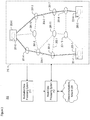
- FIG. 2 depicts a schematic diagram of telecommunications system 200 in accordance with the illustrative embodiment of the present disclosure.
- Telecommunications system 200 comprises telecommunications networks 210 and 220, evaluating data-processing system 211, and routing data-processing system 212, interrelated as shown.
- Telecommunications network 210 comprises: layer-0 nodes 201-1 through 201- M , layer-0 route segments 202-1 through 202- N , layer-2 nodes 203-1 through 203- P , and layer-2 bundle 204-1 through 204- Q , interrelated as shown.
- the integers M, N, P, and Q have values that are equal to 12, 17, 3, and 2, respectively. These integers, however, can have other values than depicted, as those who are skilled in the art will appreciate after reading this specification.
- Network 210 enables devices such as user endpoints to exchange data packets with one another.
- network 210 constitutes a wide-area network (WAN), although in some other embodiments of the present disclosure, network 210 can constitute a local-area network (LAN) or other type of network.
- Network 210 operates on Layer-2 (L-2) Provider Backbone Bridging (PBB) technology and, having one or more Ethernet rings, can be referred to as an Ethernet transport network.
- L-2 Layer-2
- PBB Provider Backbone Bridging
- Ethernet transport network The connectivity among L-2 nodes, in which an L-2 connection spanning a pair of L-2 nodes is referred to as an Ethernet bundle, are routed over underlying Layer-0 (L-0) route segments, which are optical Dense Wavelength Division Multiplexing (DWDM) segments in this case.
- An ITU-T G.8032 ring serves as the protection mechanism at the Ethernet layer.
- Layer-0 (L-0) node 201- m wherein m can have a value equal to 1 through M, inclusive, is a device that interconnects two or more layer-0 route segments. Each L-0 node supports DWDM.
- Layer-0 (L-0) route segment 202- n wherein n can have a value equal to 1 through N, inclusive, refers to the physical link or medium connecting two L-0 nodes to each other. For clarity purposes, only L-0 route 202-1 is shown, although there exists an L-0 route segment 202- n between other pairs of L-0 nodes as depicted. Each L-0 route segment supports DWDM.
- Layer-2 (L-2) node 203- p is a device that provides layer-2 (i.e., data link) computer networking functionality.
- Each L-2 node supports the Ethernet protocol and is an Ethernet point-of-presence (PoP), in some embodiments.
- PoP Ethernet point-of-presence
- Each L-2 node comprises an L-0 node as well.
- L-2 node 203-1 comprises L-0 node 201-1
- L-2 node 203-2 comprises L-0 node 201-5
- L-2 node 203-3 comprises L-0 node 201-9.
- Layer-2 (L-2) bundle 204- q refers to the data link that connects two L-2 nodes to each other.
- L-2 bundle 204-1 connects L-2 node 203-1 and 203-2
- L-2 bundle 204-2 connects L-2 node 203-2 and 203-3.
- Each L-2 bundle traverses one or more L-0 route segments between the two L-2 nodes connected by L-2 bundle 204- q .
- a series of multiple layer-2 nodes and bundles constitute a ring structure in network 210, such as nodes 203-1 through 203-3 with associated bundles 204-1 and 204-2.
- Telecommunications network 210 is characterized as having a ring network topology.
- the network can have a structure other than that of a single ring.
- network 210 can have a dual-ring structure, a mesh structure, a fully connected structure, or any other suitable structure.
- network 210 can operate on a traffic engineering technology different than PBB, can be based on a protocol different than Ethernet, can have protection switching other than ITU-T G.8032, and/or can utilize multiplexing other than DWDM.
- Evaluation data-processing system 211 is a server computer that is configured to perform at least some of the operations discussed below and in Figure 5 .
- System 211 receives information related to network topology of network 210 and other relevant information, such as layer-0 topology, existing layer-2 topology, latency, and measured availability of layer-0 route segments. Based on these and other data, system 211 discovers the location of one or more potential layer-2 nodes for future use in network 210. In some other embodiments of the present disclosure, system 211 can be based on a different computing platform.
- Evaluation data-processing system 211 can obtain the information related to network 210 from one or more sources. For example and without limitation, system 211 can receive the information via i) control paths from one or more nodes and/or links in network 210, and/or ii) data entry performed by a technician. In regard to reporting the locations of the one or more potential layer-2 nodes, system 211 can present the results to a technician (e.g., via a display, etc.) and/or can provide the results to route data-processing system 212 for further processing.
- a technician e.g., via a display, etc.
- Route data-processing system 212 is a server computer that is configured to perform routing of one or more packets through at least a portion of network 210.
- System 212 receives, from system 211, updated information related to network 210, including updated layer-2 topology, and provides an updated description of the layer-2 topology to one or more nodes in network 210, which is then used to route one or more packets.
- evaluation data-processing system 211 provides the updated description of the layer-2 topology to network 210, which is then used to route one or more packets, instead of system 212 providing the updated description.
- System 212 in some embodiments of the present disclosure, can also receive one or more packets from telecommunications network 220. Then, based on the updated layer-2 topology that is generated by evaluation data-processing system 211, can select a proper route through network 210 for each packet or stream of packets received.
- route data-processing system 212 is physically distinct from evaluation data-processing system 211.
- the operations performed by systems 211 and 212 can be performed within the same data-processing system (e.g., server computer, etc.).
- system 212 is a server computer in some embodiments, system 212 in other embodiments can be based on different computing platform.
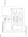
- FIG. 3 depicts a schematic diagram of evaluation data-processing system 211, in accordance with the illustrative embodiment of the present disclosure.
- System 211 can be implemented in hardware, software, or a combination of hardware and software.
- system 211 is depicted as a single server computer, software components of the functionality disclosed herein can reside in multiple server computers, or in one or more like computing devices or machines, for that matter.
- the server computers or like computing devices or machines can comprise one or more central processing units (processors) and one or more memory devices.
- processors central processing units
- system 211 comprises: processor 301, memory 302, and receiver and transmitter 303, which are interconnected as shown.
- system 211 is a server computer. As those who are skilled in the art will appreciate after reading this specification, however, system 211 can be a different type of data-processing system.
- Processor 301 is a general-purpose processor that is configured to execute an operating system and the application software that performs the operations described herein, including at least some of the operations described in Figures 4 through 8 . It will be clear to those skilled in the art how to make and use processor 301.
- Memory 302 is non-transitory and non-volatile computer storage memory technology that is well known in the art (e.g., flash memory, etc.). Memory 302 is configured to store operating system 311, application software 312, and database 313.
- the operating system is a collection of software that manages, in well-known fashion, system 211's hardware resources and provides common services for computer programs, such as those that constitute the application software.
- the application software that is executed by processor 301 enables system 211 to perform the functions disclosed herein.
- Database 313 comprises information related to network topology of network 210 and other relevant information, such as layer-0 topology, existing layer-2 topology, latency, and measured availability of layer-0 route segments. It will be clear to those skilled in the art how to make and use memory 302.
- Receiver and transmitter 303 is configured to enable system 211 to receive from and transmit to other elements within telecommunications system 200, including route data-processing system 212, telecommunications network 210, and telecommunications network 220, for example and without limitation. It will be clear to those skilled in the art how to make and use receiver and transmitter 303.
- Figures 4 through 8 depict flowcharts of the salient operations performed in accordance with the illustrative embodiment of the present disclosure. It will be clear to those having ordinary skill in the art, after reading the present disclosure, how to make and use alternative embodiments of the disclosed methods wherein the recited operations sub-operations, and messages are differently sequenced, grouped, or sub-divided - all within the scope of the present disclosure. It will be further clear to those skilled in the art, after reading the present disclosure, how to make and use alternative embodiments of the disclosed methods wherein some of the described operations, sub-operations, and messages are optional, are omitted, or are performed by other elements and/or systems.
- Figure 4 depicts a flowchart of method 400, which comprises the salient operations performed in accordance with the illustrative embodiment of the present disclosure. These operations are performed by one or more data-processing systems within telecommunications system 200.
- evaluation data-processing system 211 determines an optimal routing through telecommunications network 210. Operation 401 is described below and with reference to Figure 5 .
- telecommunications network 210 is reconfigured based on the results determined in accordance with operation 401. In some embodiments of the present disclosure, some or all of operation 403 are performed by a technician.
- route data-processing system 212 routes information pertaining to a communications service (e.g., video, voice, audio, data, telephony, etc.), in accordance with the optimal routing for one alternative of the one or more alternatives generated as described below and with reference to Figure 5 .
- a communications service e.g., video, voice, audio, data, telephony, etc.
- the information routed can be that which is transmitted between two or more parties during a telephone call.
- the information routed is in the form of packets, while in some other embodiments the information can be in the form of other types of units.
- operations 401 through 405 are performed once. However, as those who are skilled in the art will appreciated after reading this specification, the operations depicted can be performed repeatedly (e.g., periodically, sporadically, etc.). The operations can be performed proactively (e.g., before a degradation in service availability or other performance occurs, etc.) and/or reactively (e.g., as a result of a degradation in service availability or other performance occurring, etc.).
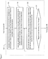
- Figure 5 depicts a flowchart of the salient sub-operations of operation 401, for discovering the locations of potential layer-2 nodes in network 210.
- evaluation data-processing system 211 receives one or more of i) a first description of an layer-0 network topology of telecommunications network 210, comprising one or more layer-0 route segments including route segment 202-1, ii) a second description of an existing layer-2 network topology of network 210, comprising an existing layer-2 route that is defined by bundles 204-1 and 204-2, and iii) one or more performance characteristics of network 210.
- Operation 501 is described in detail below and with reference to Figure 6 .
- system 211 generates one or more alternatives to the existing layer-2 route.
- Each alternative layer-2 route comprises a different potential layer-2 node selected from one or more layer-0 node locations that are identified in the first description received in accordance with operation 501. Operation 503 is described in detail below and with reference to Figure 7 .
- system 211 generates an optimal layer-0 routing for each of the one or more alternatives generated in accordance with operation 503, according to at least a first objective that is based on the first performance characteristic received in accordance with operation 501. Operation 505 is described in detail below and with reference to Figure 8 .
- system 211 selects at least a first alternative from amongst the one or more alternatives, based on the service availability of the optimal layer-0 routing generated in accordance with operation 505 of each of the one or more alternatives.
- system 211 can select at least a first alternative based on i) an objective to maximize the maximum service availability among all services in the current network setting and/or ii) an objective to maximize the minimum service availability among all services in the current network setting, as described later.
- system 211 transmits an identification (e.g., layer-2 node location or locations, etc.) of at least the first alternative to a second data-processing system such as route data-processing system 212, for example and without limitation.
- system 211 presents (e.g., displays, etc.) the identification to a technician, who can then use the information to reconfigure network 210 by adding the one or more layer-2 nodes identified.
- Figure 6 depicts a flowchart of the salient sub-operations of operation 501.
- evaluation data-processing system 211 receives the description of the layer-0 network topology of telecommunications network 210, comprising the one or more layer-0 route segments, including route segment 202-1 and others.
- system 211 receives the description of the existing layer-2 network topology of network 210, comprising the existing layer-2 route that is defined by bundles 204-1 and 204-2.
- system receives the one or more performance characteristics of network 210, including a first performance characteristic.
- the one or more performance characteristics can be related to latency, availability, and so on, for example and without limitation.
- Figure 7 depicts a flowchart of the salient sub-operations of operation 503. An overview of the operations depicted in Figure 7 is provided here.
- evaluation data-processing system 211 uses a heuristic algorithm that evaluates all alternative layer-2 nodes, concurrent with considering layer-0 routing alternatives for each layer-2 alternative. Initially, all layer-0 nodes are considered as potential new layer-2 locations. In some embodiments of the present disclosure, however, the heuristic removes from consideration one or more layer-0 nodes, in accordance with operations 701 and 703 and based on one or more criteria such as i) their proximity to existing layer-2 locations, or ii) a given minimum distance as measured from existing layer-2 locations. This approach can keep the heuristics search space manageable by eliminating nodes that have a low probability of being selected as new layer-2 node locations.
- the heuristic then generates one or more alternative layer-2 routes in accordance with operation 705, with the selected layer-0 nodes serving as potential layer-2 nodes in various combinations within each alternative.
- Each alternative is evaluated in an iteration in which the heuristic refers to a program that solves a linear program model and obtains the optimal layer-0 routing for that alternative, as described in detail below and in reference to Figure 8 .
- the heuristic considers a set of services (e.g., voice, video, data, high-quality audio, etc.) between the end layer-2 nodes of an existing ring (e.g., nodes 203-1 and 203-3, etc.) and computes the availability of each service in a new design option.
- the heuristic continues to look for a better solution according to an objective function.
- the heuristic can use two objective functions.
- system 211 can produce multiple alternative solutions.
- a first objective can be to maximize the maximum service availability among all services in the current network setting.
- the use of this objective can ensure that there exists at least one service that is as maximally available as possible.
- a second objective can be to maximize the minimum service availability among all services in the current network setting.
- the use of this objective can provide fairness to all of the services by ensuring that there is no service with an unacceptably low availability.
- any other appropriate objective can be accommodated in the heuristic.
- evaluation data-processing system 211 generates a first non-empty set (e.g., a list, etc.) of one or more layer-0 node locations that are identified in the first description received earlier, based on a first predetermined criterion.
- a first non-empty set e.g., a list, etc.
- node location(s) and “distance(s) between nodes” are used in this specification within the context of network topology and are to be understood within that context. The purpose of this is to keep the heuristics search space manageable by eliminating nodes that have a low probability of being selected as new layer-2 node locations.
- the first criterion is based on the distances of the one or more layer-0 node locations from a first predetermined layer-2 node (e.g., node 203-1, node 203-2, node 203-3, etc.) identified in the second description received earlier.
- a first predetermined layer-2 node e.g., node 203-1, node 203-2, node 203-3, etc.
- the first criterion can be based whether the one or more layer-0 node locations are i) within a predetermined distance from the first layer-2 node (e.g., node 203-1, node 203-2, node 203-3, etc.) identified in the second description received earlier, ii) at least a predetermined distance from the first layer-2 node, and/or iii) within a predetermined range of distances from the first layer-2 node.
- a predetermined distance from the first layer-2 node e.g., node 203-1, node 203-2, node 203-3, etc.
- other criteria can be used.
- system 211 optionally generates a second non-empty set (e.g., a list, etc.) of one or more layer-0 nodes that are identified in the first description received earlier, based on a second predetermined criterion.
- a second non-empty set e.g., a list, etc.
- the purpose of this is to keep the heuristics search space manageable by eliminating nodes that have a low probability of being selected as new layer-2 node locations.
- the second criterion is based on the distances of the one or more layer-0 node locations from a second predetermined layer-2 node (e.g., node 203-1, node 203-2, node 203-3, etc.) that is identified in the second description received earlier, and different than the first predetermined node referred to in operation 701.
- the second criterion can be based whether the one or more layer-0 node locations are within a predetermined distance from the second layer-2 node. As those who are skilled in the art will appreciate after reading this specification, other criteria can be used.
- system 211 In accordance with operation 705, generates an alternative layer-2 route j (i.e., "alternative j ").
- system 211 generates the alternative based on selecting, as part of a unique combination, i) a potential layer-2 node from the one or more layer-0 locations in the first set generated in accordance with operation 701 and, ii) optionally, a potential layer-2 node from the one or more layer-0 locations in the second set generated in accordance with operation 703.
- system 211 can select one or more additional, potential layer-2 nodes to be part of the unique combination.
- system 211 repeats operation 707 for J unique combinations (e.g., all unique combinations, etc.) of potential layer-2 nodes, thereby generating J alternative layer-2 routes. Afterwards, control of task execution proceeds to operation 505.
- J unique combinations e.g., all unique combinations, etc.
- Figure 8 depicts a flowchart of the salient sub-operations of operation 505.
- evaluation data-processing system 211 executes a linear program model, resulting in an optimal layer-0 routing for layer-2 alternative j that is currently under consideration.
- operation 801 will be executed for all J alternatives generated earlier.
- system 211 uses a linear program solver (i.e., CPLEX 12.2 solver).
- An important part of the linear program (LP) model being used is the objective function that governs the model.
- system 211 uses two objective functions for the LP in order to expand the solution space in layer-0, which ultimately increases the alternatives available at layer-2. Any number of objective functions can be used, however. Also, any suitable objective function can be added into the LP, as those who are skilled in the art will appreciate, in order to expand the solution space further and provide alternative routing options that can be used to form more alternative layer-2 routes.
- the first objective that system 211 uses is to minimize the overall latency.
- system 211 obtains the set of layer-0 routes with smallest latency for all bundles of a given alternative layer-2 route.
- a layer-2 route can include, in the solution space, some layer-0 segments with higher availability, even if the latency is not the most optimal.
- system 211 can use a second objective function that maximizes the overall layer-0 availability, even if it means adding an acceptable amount of latency.
- the illustrative embodiment generates an optimal layer-0 routing for each given alternative layer-2 route, based on a linear program that uses one or more objectives set forth herein.
- a linear program that uses one or more objectives set forth herein.
- alternative embodiments of the present disclosure can be made and used wherein the objective or objectives are different than disclosed herein.
- system 211 In accordance with operation 803, system 211 generates a description of the corresponding layer-2 connectivity of the alternative j, based on the optimal layer-0 routing generated in accordance with operation 801.
- system 211 evaluates the service availability of the alternative j with respect to the existing layer-2 route.
- control of task execution proceeds to operation 809 if alternative j is shown to improve service availability based on the evaluation performed in accordance with operation 805. Otherwise, control of task execution proceeds to operation 811.
- system 211 updates the set (e.g., list, etc.) of solutions to include alternative j and re-sorts the set.
- control of task execution proceeds to operation 801 until all J alternatives have been considered. Then, control of task execution proceeds to operation 507.
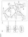
- FIG. 9 depicts a schematic diagram of telecommunications system 900 in accordance with the illustrative embodiment of the present disclosure.
- Telecommunications system 900 comprises telecommunications networks 910 and 220, evaluation data-processing system 211, and route data-processing system 212, interrelated as shown.
- Network 910 is a modified version of network 210, in that two layer-2 nodes - that is, nodes 903-1 and 903-2 - have been added as a result of system 211 performing one or more of the operations described above and with reference to Figures 5 through 8 .
- the topology reflected in Figure 9 might reflect an optimal layer-0 routing generated in accordance with operation 505.
- Network 910 comprises two Ethernet rings: one is defined by nodes 203-1, 903-1, 903-2, and 203-3 that are interconnected by bundles 904-1 through 904-3, and the other is defined by nodes 903-1, 903-2, and 203-2 that are interconnected by bundles 904-2, 904-4, and 904-5.
- network 910 is characterized as having an improved level of service availability when compared to network 210. This improved service availability is enabled by the evaluation that is performed in accordance with the operations described earlier.
- FIG 10 depicts a schematic diagram of telecommunications system 1000 in accordance with the illustrative embodiment of the present disclosure.
- Telecommunications system 1000 comprises telecommunications networks 1010 and 220, evaluation data-processing system 211, and route data-processing system 212, interrelated as shown.
- Network 1010 is a modified version of network 210, in that three layer-2 nodes - that is, nodes 1003-1, 1003-2, and 1003-3 - have been added as a result of system 211 performing one or more of the operations described above and with reference to Figures 5 through 8 .
- the topology reflected in Figure 10 might reflect an optimal layer-0 routing generated in accordance with operation 505.
- Network 1010 comprises two Ethernet rings: one is defined by nodes 203-1, 1003-1, 1003-2, and 203-3 that are interconnected by bundles 1004-1 through 1004-3, and the other is defined by nodes 1003-1, 1003-2, 1003-3, and 203-2 that are interconnected by bundles 1004-2 and 1004-4 through 1004-6.
- network 1010 is characterized as having an improved level of service availability when compared to network 210. This improved service availability is enabled by the evaluation that is performed in accordance with the operations described earlier.
Description
- The present invention relates to telecommunications in general, and, more particularly, to discovering the locations of potential layer-2 nodes to be deployed for use in a telecommunications network.
- A. Hadijantonis et al., "Evolution to a Converged discloses networking techniques including: 1) a GMPLS-based unified control plane that offers a tighter integration between layer-1 (optical transport layer) and layer-2 (Ethernet layer), 2) a fully distributed integrated routing and signaling framework for dynamically provisioning Ethernet switched paths (ESPs) at any bandwidth granularity including both full wavelength and finer granularity (sub-lambda) ESPs in an integrated Ethernet-optical networking environment, and 3) a notion of an integrated link-state advertisements strategy that is consistent with a fully integrated routing and signaling protocol.
-
WO 2008/108984 A2 discloses a method of controlling services in a communications network. The method comprises by means of a software control plane control system: storing information about hardware endpoints and communications connections in the communications network, and traffic engineering rules and network policies governing the communications network; defining services to be implemented on the communications network; computing communications paths according to the stored information to implement the defined services; programming hardware endpoints along the computed communications paths to establish the communications paths in the communications network; monitoring programmed hardware endpoints and communications connections along the computed communications paths and updating the stored information; and recomputing communications paths and reprogramming hardware endpoints along the recomputed communications paths to adapt the communications paths according to changes in the stored information and services to ensure implementation of the services. -
US 2013/0108263 A1 discloses data center network architectures that can reduce the cost and complexity of data center networks. The data center network architectures can employ optical network topologies and optical nodes to efficiently allocate bandwidth within the data center networks, while reducing the physical interconnectivity requirements of the data center networks. The data center network architectures also allow computing resources within data center networks to be controlled and provisioned based at least in part on a combined network topology and application component topology. -
Figure 1A depicts a schematic diagram of a portion of a telecommunications system in the prior art. The depicted portion includestelecommunications network 110, which comprises: layer-0 nodes 101-1 through 101-12, layer-0 route segments 102-1 through 102-17, layer-2 nodes 103-1 through 103-3, and layer-2 bundle 104-1 through 104-2. The elements withintelecommunications network 110 are interrelated as shown. - Network 110 enables devices such as user endpoints to exchange data packets with one another. In particular,
network 110 constitutes a wide-area network (WAN), although it could alternatively constitute a local-area network (LAN) or other type of network. Network 110 operates on Layer-2 (L-2) Provider Backbone Bridging (PBB) technology and, having one or more Ethernet rings, can be referred to as an Ethernet transport network. The connectivity among L-2 nodes, in which an L-2 connection spanning a pair of L-2 nodes is referred to as an Ethernet bundle, are routed over underlying Layer-0 (L-0) route segments, which are optical Dense Wavelength Division Multiplexing (DWDM) segments in this case. An ITU-T G.8032 ring serves as the protection mechanism at the Ethernet layer. - Layer-0 (L-0) node 101-m, wherein m can have a value equal to 1 through 12, inclusive, is a device that interconnects two or more layer-0 route segments. Each L-0 node supports DWDM.
- Layer-0 (L-0) route segment 102-n, wherein n can have a value equal to 1 through 17, inclusive, refers to the physical link or medium connecting two L-0 nodes to each other. For clarity purposes, only L-0 route 102-1 is shown, although there exists an L-0 route segment 102-n between other pairs of L-0 nodes as depicted. Each L-0 route segment supports DWDM.
- Layer-2 (L-2) node 103-p, wherein p can have a value equal to 1 through 3, inclusive, is a device that provides layer-2 (i.e., data link) computer networking functionality. Each L-2 node supports the Ethernet protocol. Each L-2 node comprises an L-0 node as well. As depicted, L-2 node 103-1 comprises L-0 node 101-1, L-2 node 103-2 comprises L-0 node 101-5, and L-2 node 103-3 comprises L-0 node 101-9.
- Layer-2 (L-2) bundle 104-q, wherein q can have a value equal to 1 or 2, inclusive, refers to the data link that connects two L-2 nodes to each other. As depicted, L-2 bundle 104-1 connects L-2 node 103-1 and 103-2, and L-2 bundle 104-2 connects L-2 node 103-2 and 103-3. Each L-2 bundle traverses one or more L-0 route segments between the two L-2 nodes connected by L-2 bundle 104-q.
- There are situations in which the data packet routing performed within telecommunications system 100 can be disrupted. For example, and as depicted in
Figure 1B , a physical link can be cut, as represented bycable break 105. As depicted,break 105 has disrupted the L-0 route segment between L-0 nodes 101-6 and 101-7 and, consequently, has disrupted the L-2 bundle between L-2 nodes 103-2 and 103-3. Depending on various factors, such disruptions can be frequent, and multiple disruptions can occur simultaneously with one another. - Therefore, what is needed is a technique for improving service availability that avoids at least some of the disadvantages in the prior art.
- The invention enables the discovery and identification of locations at which to deploy new Layer-2 nodes within a telecommunications network, without at least some of the disadvantages in the prior art. The disclosed technique is intended to identify Layer-2 nodes at locations where they can improve service availability when deployed, especially in geographic regions that suffer frequent or simultaneous cable breaks, or both. In accordance with the illustrative embodiment of the present disclosure, the locations of the new Layer-2 nodes depend on the underlying Layer-0 network topology, as well as on the existing Layer-2 topology. Thus, the disclosed technique features a cross-layer approach - that is, across Layer-2 and Layer-0 - that takes these factors into account and evaluates the locations in a way that can considerably increase the availability of one or more services offered in the telecommunications network.
- The disclosed technique receives as inputs i) a layer-0 (L-0) network topology description of L-0 nodes and L-0 links, ii) the latency and/or availability of each L-0 link, and iii) a description of the existing layer-2 (L-2) topology. Using these inputs, the technique determines and presents new locations for L-2 nodes and L-0 routes for new L-2 bundles, as well as for the existing L-2 bundles, if needed, while maximizing the L-2 service availability. Because the L-2 service availability in a network relies highly on the availability of underlying L-0 route segments, the selection of L-0 segments across all of the L-2 bundles that make up an end-to-end path along an illustrative Ethernet ring is significantly important in designing Ethernet networks. Thus, the illustrative embodiment considers the available design alternatives of these two layers (L-0 and L-2) in order to obtain an optimal solution.
- The illustrative embodiment considers the available design alternatives in accordance with two salient parts of the disclosed technique. The first part of the technique includes using a heuristic algorithm that looks for better network design alternatives, by moving from one alternative layer-2 route to another and exploring all potential L-2 node locations in the network. The second part of the technique includes leveraging a linear programming model for obtaining optimal L-0 routing for a given alternative layer-2 route.
- The disclosed technique is further based on the following insight made by the inventors. An illustrative Ethernet ring is comprised of a set of L-2 nodes and L-2 connectivity among those nodes. To select L-0 route segments for a first L-2 bundle of an Ethernet ring, one could choose a pair of L-2 nodes and execute an efficient routing algorithm to find the best available L-0 route for that particular pair of nodes. A similar process could be followed to obtain L-0 routes for all additional Ethernet bundles that make up the ring. Depending on the routing algorithm used, one could obtain a best possible L-0 route between a given pair of L-2 nodes.
- As recognized by the inventors, however, this process of finding L-0 routes for all bundles in a sequential manner does not guarantee an optimal set of bundles to make up a ring. This is because the underlying L-0 route segments that coincide with the routes of the Ethernet (L-2) bundles within a ring have a specific requirement: the combined set of bundles must consist of completely disjoint L-0 route segments. Hence, the L-0 routings of the Ethernet bundles within a ring are not independent of one another. Thus, a combined approach of routing for all bundles within a ring is necessary in order to obtain optimal routing. As a result, the technique of the illustrative embodiment features an optimization model that is designed to obtain the L-0 routes of all Ethernet bundles that are considered in the L-2 network architecture.
- The technique disclosed herein interworks with a telecommunications network that is based on Ethernet rings with underlying DWDM capability. As those who are skilled in the art will appreciate after reading this specification, however, the technique can be used in conjunction with a network that is based on a different Layer-2 or a different Layer-0, or both.
- A first illustrative method comprises: receiving, by a data-processing system, i) a first description of an layer-0 network topology of a telecommunications network, comprising one or more layer-0 route segments, ii) a second description of an existing layer-2 network topology of the telecommunications network, comprising an existing layer-2 route, and iii) a first performance characteristic of the telecommunications network; generating, by the data-processing system, one or more alternatives to the existing layer-2 route, wherein each of the one or more alternatives comprises a different potential layer-2 node selected from one or more layer-0 node locations that are identified in the first description; generating, by the data-processing system, an optimal layer-0 routing for each of the one or more alternatives, according to a first objective that is based on the first performance characteristic; and routing one or more packets according to the optimal layer-0 routing for one of the one or more alternatives generated by the data-processing system.
- A second illustrative method comprises: receiving, by a data-processing system, i) a first description of an layer-0 network topology of a telecommunications network, comprising one or more layer-0 route segments, ii) a second description of an existing layer-2 network topology of the telecommunications network, comprising an existing layer-2 route, and iii) a first performance characteristic of the telecommunications network; generating, by the data-processing system, i) a first non-empty set of one or more layer-0 node locations that are identified in the first description, based on a first predetermined criterion, and ii) a second non-empty set of one or more layer-0 nodes that are identified in the first description, based on a second predetermined criterion; generating, by the data-processing system, one or more alternatives to the existing layer-2 route, wherein each of the one or more alternatives comprises a unique combination of i) a potential layer-2 node selected from the one or more layer-0 node locations in the first set and ii) a potential layer-2 node selected from the one or more layer-0 node locations in the second set; generating, by the data-processing system, an optimal layer-0 routing for each of the one or more alternatives, according to a first objective that is based on the first performance characteristic; and routing one or more packets according to the optimal layer-0 routing for one of the one or more alternatives generated by the data-processing system.
- A third illustrative method comprises: receiving, by a data-processing system, i) a first description of an layer-0 network topology of a telecommunications network, comprising one or more layer-0 route segments, ii) a second description of an existing layer-2 network topology of the telecommunications network, comprising an existing layer-2 route, and iii) a first performance characteristic of the telecommunications network; generating, by the data-processing system, a first non-empty set of one or more layer-0 node locations that are identified in the first description, based on a first predetermined criterion; generating, by the data-processing system, one or more alternatives to the existing layer-2 route, wherein each of the one or more alternatives comprises a different potential layer-2 node selected from the one or more layer-0 node locations in the first set; generating, by the data-processing system, an optimal layer-0 routing for each of the one or more alternatives, according to a first objective that is based on the first performance characteristic; selecting, by the data-processing system, an alternative from amongst the one or more alternatives, based on service availability of the optimal layer-0 routing of each of the one or more alternatives; and transmitting, by the data-processing system, an identification of the potential layer-2 node that corresponds to the optimal layer-0 routing for the alternative selected.
-
-
Figures 1A and 1B depict schematic diagrams of a portion of a telecommunications system in the prior art. -
Figure 2 depicts a schematic diagram oftelecommunications system 200 in accordance with the illustrative embodiment of the present disclosure. -
Figure 3 depicts a schematic diagram of evaluation data-processing system 211, in accordance with the illustrative embodiment of the present disclosure. -
Figure 4 depicts a flowchart ofmethod 400, which comprises the salient operations performed in accordance with the illustrative embodiment of the present disclosure. -
Figure 5 depicts a flowchart of the salient sub-operations ofoperation 401. -
Figure 6 depicts a flowchart of the salient sub-operations ofoperation 501. -
Figure 7 depicts a flowchart of the salient sub-operations ofoperation 503. -
Figure 8 depicts a flowchart of the salient sub-operations ofoperation 505. -
Figure 9 depicts a schematic diagram oftelecommunications system 900 in accordance with the illustrative embodiment of the present disclosure. -
Figure 10 depicts a schematic diagram oftelecommunications system 1000 in accordance with the illustrative embodiment of the present disclosure. - Layer 0 - For the purposes of this specification and the claims, "
layer 0" is defined as the transmission medium or media in data communication network. - Layer 2 - For the purposes of this specification and the claims, "
layer 2" is defined as the Data Link layer of the Open Systems Interconnection (OSI) communication model. - Route segment - For the purposes of this specification and the claims, "route segment" is defined as the transmission medium path between two layer-0 nodes, with no other layer-0 nodes in between.
- Network topology - For the purposes of this specification and the claims, "network topology" is defined as the arrangement of various elements (e.g., nodes, links, etc.) of a computer network or other telecommunications network. It may be depicted physically or logically.
- Bundle - For the purposes of this specification and the claims, "bundle" is defined as the layer-2 connectivity between two layer-2 nodes, with no other layer-2 nodes in between.
- Layer-2 route - For the purposes of this specification and the claims, "layer-2 route" is defined as all of the bundles that constitute a path between two specified layer-2 nodes. A layer-2 route may have, but is not required to have, one or more layer-2 nodes along the path and in between the two specified nodes.
- Existing layer-2 route - For the purposes of this specification and the claims, "existing layer-2 route" is defined as a layer-2 route that is in operation at the time under consideration.
- Alternative layer-2 route - For the purposes of this specification and the claims, "alternative layer-2 route" is defined as a layer-2 route that is under consideration as a replacement to an existing layer-2 route.
- Potential layer-2 node - For the purposes of this specification and the claims, "potential layer-2 node" is defined as a layer-2 node that is not one of existing layer-2 nodes but forms a layer-2 route being considered to be deployed to an existing network topology.
-
Figure 2 depicts a schematic diagram oftelecommunications system 200 in accordance with the illustrative embodiment of the present disclosure.Telecommunications system 200 comprisestelecommunications networks processing system 211, and routing data-processing system 212, interrelated as shown. -
Telecommunications network 210 comprises: layer-0 nodes 201-1 through 201-M, layer-0 route segments 202-1 through 202-N, layer-2 nodes 203-1 through 203-P, and layer-2 bundle 204-1 through 204-Q, interrelated as shown. As depicted, the integers M, N, P, and Q have values that are equal to 12, 17, 3, and 2, respectively. These integers, however, can have other values than depicted, as those who are skilled in the art will appreciate after reading this specification. -
Network 210 enables devices such as user endpoints to exchange data packets with one another. In particular,network 210 constitutes a wide-area network (WAN), although in some other embodiments of the present disclosure,network 210 can constitute a local-area network (LAN) or other type of network.Network 210 operates on Layer-2 (L-2) Provider Backbone Bridging (PBB) technology and, having one or more Ethernet rings, can be referred to as an Ethernet transport network. The connectivity among L-2 nodes, in which an L-2 connection spanning a pair of L-2 nodes is referred to as an Ethernet bundle, are routed over underlying Layer-0 (L-0) route segments, which are optical Dense Wavelength Division Multiplexing (DWDM) segments in this case. An ITU-T G.8032 ring serves as the protection mechanism at the Ethernet layer. - Layer-0 (L-0) node 201-m, wherein m can have a value equal to 1 through M, inclusive, is a device that interconnects two or more layer-0 route segments. Each L-0 node supports DWDM.
- Layer-0 (L-0) route segment 202-n, wherein n can have a value equal to 1 through N, inclusive, refers to the physical link or medium connecting two L-0 nodes to each other. For clarity purposes, only L-0 route 202-1 is shown, although there exists an L-0 route segment 202-n between other pairs of L-0 nodes as depicted. Each L-0 route segment supports DWDM.
- Layer-2 (L-2) node 203-p, wherein p can have a value equal to 1 through P, inclusive, is a device that provides layer-2 (i.e., data link) computer networking functionality. Each L-2 node supports the Ethernet protocol and is an Ethernet point-of-presence (PoP), in some embodiments. Each L-2 node comprises an L-0 node as well. As depicted, L-2 node 203-1 comprises L-0 node 201-1, L-2 node 203-2 comprises L-0 node 201-5, and L-2 node 203-3 comprises L-0 node 201-9.
- Layer-2 (L-2) bundle 204-q, wherein q can have a value equal to 1 through Q, inclusive, refers to the data link that connects two L-2 nodes to each other. As depicted, L-2 bundle 204-1 connects L-2 node 203-1 and 203-2, and L-2 bundle 204-2 connects L-2 node 203-2 and 203-3. Each L-2 bundle traverses one or more L-0 route segments between the two L-2 nodes connected by L-2 bundle 204-q. A series of multiple layer-2 nodes and bundles constitute a ring structure in
network 210, such as nodes 203-1 through 203-3 with associated bundles 204-1 and 204-2. -
Telecommunications network 210 is characterized as having a ring network topology. One of ordinary skill in the art will recognize, however, that the network can have a structure other than that of a single ring. Thus, in one or more other embodiments,network 210 can have a dual-ring structure, a mesh structure, a fully connected structure, or any other suitable structure. Furthermore, in other embodiments of the present disclosure,network 210 can operate on a traffic engineering technology different than PBB, can be based on a protocol different than Ethernet, can have protection switching other than ITU-T G.8032, and/or can utilize multiplexing other than DWDM. - Evaluation data-
processing system 211 is a server computer that is configured to perform at least some of the operations discussed below and inFigure 5 .System 211 receives information related to network topology ofnetwork 210 and other relevant information, such as layer-0 topology, existing layer-2 topology, latency, and measured availability of layer-0 route segments. Based on these and other data,system 211 discovers the location of one or more potential layer-2 nodes for future use innetwork 210. In some other embodiments of the present disclosure,system 211 can be based on a different computing platform. - Evaluation data-
processing system 211 can obtain the information related tonetwork 210 from one or more sources. For example and without limitation,system 211 can receive the information via i) control paths from one or more nodes and/or links innetwork 210, and/or ii) data entry performed by a technician. In regard to reporting the locations of the one or more potential layer-2 nodes,system 211 can present the results to a technician (e.g., via a display, etc.) and/or can provide the results to route data-processing system 212 for further processing. - Route data-
processing system 212 is a server computer that is configured to perform routing of one or more packets through at least a portion ofnetwork 210.System 212 receives, fromsystem 211, updated information related tonetwork 210, including updated layer-2 topology, and provides an updated description of the layer-2 topology to one or more nodes innetwork 210, which is then used to route one or more packets. In some embodiments of the present disclosure, evaluation data-processing system 211 provides the updated description of the layer-2 topology to network 210, which is then used to route one or more packets, instead ofsystem 212 providing the updated description. -
System 212, in some embodiments of the present disclosure, can also receive one or more packets fromtelecommunications network 220. Then, based on the updated layer-2 topology that is generated by evaluation data-processing system 211, can select a proper route throughnetwork 210 for each packet or stream of packets received. - As depicted, route data-
processing system 212 is physically distinct from evaluation data-processing system 211. However, as those who are skilled in the art will appreciate after reading this specification, the operations performed bysystems system 212 is a server computer in some embodiments,system 212 in other embodiments can be based on different computing platform. -
Figure 3 depicts a schematic diagram of evaluation data-processing system 211, in accordance with the illustrative embodiment of the present disclosure.System 211 can be implemented in hardware, software, or a combination of hardware and software. Althoughsystem 211 is depicted as a single server computer, software components of the functionality disclosed herein can reside in multiple server computers, or in one or more like computing devices or machines, for that matter. The server computers or like computing devices or machines can comprise one or more central processing units (processors) and one or more memory devices. The structure and function of such server computers and the like are well known to those skilled in the art. - In accordance with the illustrative embodiment of the present disclosure,
system 211 comprises:processor 301,memory 302, and receiver andtransmitter 303, which are interconnected as shown. In accordance with the illustrative embodiment of the present disclosure,system 211 is a server computer. As those who are skilled in the art will appreciate after reading this specification, however,system 211 can be a different type of data-processing system. -
Processor 301 is a general-purpose processor that is configured to execute an operating system and the application software that performs the operations described herein, including at least some of the operations described inFigures 4 through 8 . It will be clear to those skilled in the art how to make and useprocessor 301. -
Memory 302 is non-transitory and non-volatile computer storage memory technology that is well known in the art (e.g., flash memory, etc.).Memory 302 is configured to storeoperating system 311,application software 312, anddatabase 313. The operating system is a collection of software that manages, in well-known fashion,system 211's hardware resources and provides common services for computer programs, such as those that constitute the application software. The application software that is executed byprocessor 301 enablessystem 211 to perform the functions disclosed herein.Database 313 comprises information related to network topology ofnetwork 210 and other relevant information, such as layer-0 topology, existing layer-2 topology, latency, and measured availability of layer-0 route segments. It will be clear to those skilled in the art how to make and usememory 302. - Receiver and
transmitter 303 is configured to enablesystem 211 to receive from and transmit to other elements withintelecommunications system 200, including route data-processing system 212,telecommunications network 210, andtelecommunications network 220, for example and without limitation. It will be clear to those skilled in the art how to make and use receiver andtransmitter 303. -
Figures 4 through 8 depict flowcharts of the salient operations performed in accordance with the illustrative embodiment of the present disclosure. It will be clear to those having ordinary skill in the art, after reading the present disclosure, how to make and use alternative embodiments of the disclosed methods wherein the recited operations sub-operations, and messages are differently sequenced, grouped, or sub-divided - all within the scope of the present disclosure. It will be further clear to those skilled in the art, after reading the present disclosure, how to make and use alternative embodiments of the disclosed methods wherein some of the described operations, sub-operations, and messages are optional, are omitted, or are performed by other elements and/or systems. -
Figure 4 depicts a flowchart ofmethod 400, which comprises the salient operations performed in accordance with the illustrative embodiment of the present disclosure. These operations are performed by one or more data-processing systems withintelecommunications system 200. - In accordance with
operation 401, evaluation data-processing system 211 determines an optimal routing throughtelecommunications network 210.Operation 401 is described below and with reference toFigure 5 . - In accordance with
operation 403,telecommunications network 210 is reconfigured based on the results determined in accordance withoperation 401. In some embodiments of the present disclosure, some or all ofoperation 403 are performed by a technician. - In accordance with
operation 405, route data-processing system 212 routes information pertaining to a communications service (e.g., video, voice, audio, data, telephony, etc.), in accordance with the optimal routing for one alternative of the one or more alternatives generated as described below and with reference toFigure 5 . For example and without limitation, the information routed can be that which is transmitted between two or more parties during a telephone call. In accordance with the illustrative embodiment, the information routed is in the form of packets, while in some other embodiments the information can be in the form of other types of units. - As depicted,
operations 401 through 405 are performed once. However, as those who are skilled in the art will appreciated after reading this specification, the operations depicted can be performed repeatedly (e.g., periodically, sporadically, etc.). The operations can be performed proactively (e.g., before a degradation in service availability or other performance occurs, etc.) and/or reactively (e.g., as a result of a degradation in service availability or other performance occurring, etc.). -
Figure 5 depicts a flowchart of the salient sub-operations ofoperation 401, for discovering the locations of potential layer-2 nodes innetwork 210. In accordance withoperation 501, evaluation data-processing system 211 receives one or more of i) a first description of an layer-0 network topology oftelecommunications network 210, comprising one or more layer-0 route segments including route segment 202-1, ii) a second description of an existing layer-2 network topology ofnetwork 210, comprising an existing layer-2 route that is defined by bundles 204-1 and 204-2, and iii) one or more performance characteristics ofnetwork 210.Operation 501 is described in detail below and with reference toFigure 6 . - In accordance with
operation 503,system 211 generates one or more alternatives to the existing layer-2 route. Each alternative layer-2 route comprises a different potential layer-2 node selected from one or more layer-0 node locations that are identified in the first description received in accordance withoperation 501.Operation 503 is described in detail below and with reference toFigure 7 . - In accordance with
operation 505,system 211 generates an optimal layer-0 routing for each of the one or more alternatives generated in accordance withoperation 503, according to at least a first objective that is based on the first performance characteristic received in accordance withoperation 501.Operation 505 is described in detail below and with reference toFigure 8 . - In accordance with
operation 507,system 211 selects at least a first alternative from amongst the one or more alternatives, based on the service availability of the optimal layer-0 routing generated in accordance withoperation 505 of each of the one or more alternatives. In some embodiments of the present disclosure,system 211 can select at least a first alternative based on i) an objective to maximize the maximum service availability among all services in the current network setting and/or ii) an objective to maximize the minimum service availability among all services in the current network setting, as described later. - In accordance with
operation 509,system 211 transmits an identification (e.g., layer-2 node location or locations, etc.) of at least the first alternative to a second data-processing system such as route data-processing system 212, for example and without limitation. In some other embodiments of the present disclosure,system 211 presents (e.g., displays, etc.) the identification to a technician, who can then use the information to reconfigurenetwork 210 by adding the one or more layer-2 nodes identified. -
Figure 6 depicts a flowchart of the salient sub-operations ofoperation 501. In accordance withoperation 601, evaluation data-processing system 211 receives the description of the layer-0 network topology oftelecommunications network 210, comprising the one or more layer-0 route segments, including route segment 202-1 and others. - In accordance with
operation 603,system 211 receives the description of the existing layer-2 network topology ofnetwork 210, comprising the existing layer-2 route that is defined by bundles 204-1 and 204-2. - In accordance with
operation 605, system receives the one or more performance characteristics ofnetwork 210, including a first performance characteristic. The one or more performance characteristics can be related to latency, availability, and so on, for example and without limitation. -
Figure 7 depicts a flowchart of the salient sub-operations ofoperation 503. An overview of the operations depicted inFigure 7 is provided here. In accordance with the illustrative embodiment of the present disclosure, evaluation data-processing system 211 uses a heuristic algorithm that evaluates all alternative layer-2 nodes, concurrent with considering layer-0 routing alternatives for each layer-2 alternative. Initially, all layer-0 nodes are considered as potential new layer-2 locations. In some embodiments of the present disclosure, however, the heuristic removes from consideration one or more layer-0 nodes, in accordance withoperations - The heuristic then generates one or more alternative layer-2 routes in accordance with
operation 705, with the selected layer-0 nodes serving as potential layer-2 nodes in various combinations within each alternative. Each alternative is evaluated in an iteration in which the heuristic refers to a program that solves a linear program model and obtains the optimal layer-0 routing for that alternative, as described in detail below and in reference toFigure 8 . In accordance with the illustrative embodiment of the present disclosure, the heuristic considers a set of services (e.g., voice, video, data, high-quality audio, etc.) between the end layer-2 nodes of an existing ring (e.g., nodes 203-1 and 203-3, etc.) and computes the availability of each service in a new design option. The heuristic continues to look for a better solution according to an objective function. - In some embodiments of the present disclosure, the heuristic can use two objective functions. As a result,
system 211 can produce multiple alternative solutions. A first objective can be to maximize the maximum service availability among all services in the current network setting. The use of this objective can ensure that there exists at least one service that is as maximally available as possible. A second objective can be to maximize the minimum service availability among all services in the current network setting. The use of this objective can provide fairness to all of the services by ensuring that there is no service with an unacceptably low availability. As those who are skilled in the art will appreciate after reading this specification, any other appropriate objective can be accommodated in the heuristic. - In accordance with
operation 701, evaluation data-processing system 211 generates a first non-empty set (e.g., a list, etc.) of one or more layer-0 node locations that are identified in the first description received earlier, based on a first predetermined criterion. The terms "node location(s)" and "distance(s) between nodes" are used in this specification within the context of network topology and are to be understood within that context. The purpose of this is to keep the heuristics search space manageable by eliminating nodes that have a low probability of being selected as new layer-2 node locations. In accordance with the illustrative embodiment, the first criterion is based on the distances of the one or more layer-0 node locations from a first predetermined layer-2 node (e.g., node 203-1, node 203-2, node 203-3, etc.) identified in the second description received earlier. In various embodiments of the present disclosure, the first criterion can be based whether the one or more layer-0 node locations are i) within a predetermined distance from the first layer-2 node (e.g., node 203-1, node 203-2, node 203-3, etc.) identified in the second description received earlier, ii) at least a predetermined distance from the first layer-2 node, and/or iii) within a predetermined range of distances from the first layer-2 node. As those who are skilled in the art will appreciate after reading this specification, other criteria can be used. - In accordance with
operation 703,system 211 optionally generates a second non-empty set (e.g., a list, etc.) of one or more layer-0 nodes that are identified in the first description received earlier, based on a second predetermined criterion. The purpose of this is to keep the heuristics search space manageable by eliminating nodes that have a low probability of being selected as new layer-2 node locations. In accordance with the illustrative embodiment, the second criterion is based on the distances of the one or more layer-0 node locations from a second predetermined layer-2 node (e.g., node 203-1, node 203-2, node 203-3, etc.) that is identified in the second description received earlier, and different than the first predetermined node referred to inoperation 701. In some embodiments of the present disclosure, the second criterion can be based whether the one or more layer-0 node locations are within a predetermined distance from the second layer-2 node. As those who are skilled in the art will appreciate after reading this specification, other criteria can be used. - In accordance with
operation 705, generates an alternative layer-2 route j (i.e., "alternative j"). In accordance with the illustrative embodiment of the present disclosure,system 211 generates the alternative based on selecting, as part of a unique combination, i) a potential layer-2 node from the one or more layer-0 locations in the first set generated in accordance withoperation 701 and, ii) optionally, a potential layer-2 node from the one or more layer-0 locations in the second set generated in accordance withoperation 703. In some embodiments of the present disclosure,system 211 can select one or more additional, potential layer-2 nodes to be part of the unique combination. - In accordance with
operation 707,system 211 repeatsoperation 707 for J unique combinations (e.g., all unique combinations, etc.) of potential layer-2 nodes, thereby generating J alternative layer-2 routes. Afterwards, control of task execution proceeds tooperation 505. -
Figure 8 depicts a flowchart of the salient sub-operations ofoperation 505. In accordance withoperation 801, evaluation data-processing system 211 executes a linear program model, resulting in an optimal layer-0 routing for layer-2 alternative j that is currently under consideration. As depicted,operation 801 will be executed for all J alternatives generated earlier. - In accordance with the illustrative embodiment of the present disclosure,
system 211 uses a linear program solver (i.e., CPLEX 12.2 solver). An important part of the linear program (LP) model being used is the objective function that governs the model. In accordance with the illustrative embodiment,system 211 uses two objective functions for the LP in order to expand the solution space in layer-0, which ultimately increases the alternatives available at layer-2. Any number of objective functions can be used, however. Also, any suitable objective function can be added into the LP, as those who are skilled in the art will appreciate, in order to expand the solution space further and provide alternative routing options that can be used to form more alternative layer-2 routes. - The first objective that
system 211 uses is to minimize the overall latency. By using this objective function,system 211 obtains the set of layer-0 routes with smallest latency for all bundles of a given alternative layer-2 route. However, because the difference in latency between layer-0 route segments in a telecommunications network (e.g., a regional network, etc.) might be small, in some embodiments a layer-2 route can include, in the solution space, some layer-0 segments with higher availability, even if the latency is not the most optimal. Hence,system 211 can use a second objective function that maximizes the overall layer-0 availability, even if it means adding an acceptable amount of latency. - Computing the availability As of a series of K layer-0 route segments (As = A1 * A2 * ... * AK ) for an Ethernet bundle can introduce non-linearity, however, thereby making the problem unsolvable to optimality. As a result, and in some embodiments of the present disclosure, the original non-linear availability equation can be replaced with a linear equation

- As described in the overview above, the illustrative embodiment generates an optimal layer-0 routing for each given alternative layer-2 route, based on a linear program that uses one or more objectives set forth herein. However, as those who are skilled in the art will appreciate after reading the present disclosure, alternative embodiments of the present disclosure can be made and used wherein the objective or objectives are different than disclosed herein. Likewise, it will be clear to those having ordinary skill in the art, after reading the present disclosure, how to make and use alternative embodiments that generates an optimal layer-0 routing by using something other than a linear programming technique.
- In accordance with
operation 803,system 211 generates a description of the corresponding layer-2 connectivity of the alternative j, based on the optimal layer-0 routing generated in accordance withoperation 801. - In accordance with
operation 805,system 211 evaluates the service availability of the alternative j with respect to the existing layer-2 route. - In accordance with
operation 807, control of task execution proceeds tooperation 809 if alternative j is shown to improve service availability based on the evaluation performed in accordance withoperation 805. Otherwise, control of task execution proceeds tooperation 811. - In accordance with
operation 809,system 211 updates the set (e.g., list, etc.) of solutions to include alternative j and re-sorts the set. - In accordance with
operation 811, control of task execution proceeds tooperation 801 until all J alternatives have been considered. Then, control of task execution proceeds tooperation 507. -
Figure 9 depicts a schematic diagram oftelecommunications system 900 in accordance with the illustrative embodiment of the present disclosure.Telecommunications system 900 comprisestelecommunications networks processing system 211, and route data-processing system 212, interrelated as shown.Network 910 is a modified version ofnetwork 210, in that two layer-2 nodes - that is, nodes 903-1 and 903-2 - have been added as a result ofsystem 211 performing one or more of the operations described above and with reference toFigures 5 through 8 . Notably, the topology reflected inFigure 9 might reflect an optimal layer-0 routing generated in accordance withoperation 505. -
Network 910 comprises two Ethernet rings: one is defined by nodes 203-1, 903-1, 903-2, and 203-3 that are interconnected by bundles 904-1 through 904-3, and the other is defined by nodes 903-1, 903-2, and 203-2 that are interconnected by bundles 904-2, 904-4, and 904-5. As a result of having two rings, instead of a single ring,network 910 is characterized as having an improved level of service availability when compared tonetwork 210. This improved service availability is enabled by the evaluation that is performed in accordance with the operations described earlier. -
Figure 10 depicts a schematic diagram oftelecommunications system 1000 in accordance with the illustrative embodiment of the present disclosure.Telecommunications system 1000 comprisestelecommunications networks processing system 211, and route data-processing system 212, interrelated as shown.Network 1010 is a modified version ofnetwork 210, in that three layer-2 nodes - that is, nodes 1003-1, 1003-2, and 1003-3 - have been added as a result ofsystem 211 performing one or more of the operations described above and with reference toFigures 5 through 8 . Notably, the topology reflected inFigure 10 might reflect an optimal layer-0 routing generated in accordance withoperation 505. -
Network 1010 comprises two Ethernet rings: one is defined by nodes 203-1, 1003-1, 1003-2, and 203-3 that are interconnected by bundles 1004-1 through 1004-3, and the other is defined by nodes 1003-1, 1003-2, 1003-3, and 203-2 that are interconnected by bundles 1004-2 and 1004-4 through 1004-6. As a result of having two rings, instead of a single ring,network 1010 is characterized as having an improved level of service availability when compared tonetwork 210. This improved service availability is enabled by the evaluation that is performed in accordance with the operations described earlier. - It is to be understood that the disclosure teaches just one example of the illustrative embodiment and that many variations of the invention can easily be devised by those skilled in the art after reading this disclosure and that the scope of the present invention is to be determined by the following claims.
Claims (15)
- A method comprising:receiving (501), by a data-processing system (211),i) a first description of a layer-0 network topology of a telecommunications network, comprising one or more layer-0 route segments,ii) a second description of an existing layer-2 network topology of the telecommunications network, comprising an existing layer-2 route, andiii) a first performance characteristic of the telecommunications network;characterized in that it further comprises:generating (503), by the data-processing system (211), one or more alternatives to the existing layer-2 route, wherein each of the one or more alternatives comprises a different potential layer-2 node selected from one or more layer-0 node locations that are identified in the first description;generating (505), by the data-processing system (211), an optimal layer-0 routing for each of the one or more alternatives, according to a first objective that is based on the first performance characteristic; androuting (405) one or more packets according to the optimal layer-0 routing for one of the one or more alternatives generated by the data-processing system (211).
- The method of claim 1 further comprising generating a non-empty set of one or more layer-0 node locations that are identified in the first description, based on their distance from a predetermined layer-2 node that is identified in the second description, wherein the generating of the one or more alternatives is further based on the set,
wherein the generating of the one or more alternatives may further comprise selecting a layer-2 node from the one or more layer-0 locations in the set. - The method of claim 1 or 2, wherein the first performance characteristic considers latency through at least some of the one or more layer-0 route segments, the first objective being to minimize overall latency through a given alternative of the one or more alternatives; or
wherein the first performance characteristic considers unavailability through at least some of the one or more layer-0 route segments, the first objective being to minimize overall unavailability through a given alternative of the one or more alternatives. - The method of any one of claims 1 to 3, wherein the generating of the optimal layer-0 routing for each of the one or more alternatives is also in accordance with a second objective that is based on a second performance characteristic, wherein the second performance characteristic considers unavailability through at least some of the one or more layer-0 route segments, wherein the second objective is to minimize overall unavailability through a given alternative of the one or more alternatives.
- The method of any one of claims 1 to 4, wherein the generating of the one or more alternatives to the existing layer-2 route is based on a plurality of services provided across the existing layer-2 route, wherein each of the one or more alternatives is based on service availability for each service in the plurality.
- The method of any one of claims 1 to 5, further comprising selecting an alternative from amongst the one or more alternatives, based on service availability of the optimal layer-0 routing of each of the one or more alternatives, wherein the routing is in accordance with the alternative selected,
wherein the method may further comprise, by the data-processing system (211), transmitting an identification of the potential layer-2 node that corresponds to the optimal layer-0 routing for the alternative. - The method according to any one of claims 1 to 6, further comprising:generating, by the data-processing system (211), i) a first non-empty set of one or more layer-0 node locations that are identified in the first description, based on a first predetermined criterion, and ii) a second non-empty set of one or more layer-0 nodes that are identified in the first description, based on a second predetermined criterion;wherein each of the one or more alternatives comprises a unique combination of i) a potential layer-2 node selected from the one or more layer-0 node locations in the first set and ii) a potential layer-2 node selected from the one or more layer-0 node locations in the second set.
- The method of claim 7, wherein the first predetermined criterion and the second predetermined criterion are based on the distances of the one or more layer-0 node locations from a first predetermined layer-2 node that is identified in the second description and from a second predetermined layer-2 node that is identified in the second description, respectively.
- The method of claim 7 or 8, wherein the first performance characteristic considers latency through at least some of the one or more layer-0 route segments, the first objective being to minimize overall latency through a given alternative of the one or more alternatives; or
wherein the first performance characteristic considers unavailability through at least some of the one or more layer-0 route segments, the first objective being to minimize overall unavailability through a given alternative of the one or more alternatives. - The method of any one of claims 7 to 9, wherein the generating of the one or more alternatives to the existing layer-2 route is based on a plurality of services provided across the existing layer-2 route, wherein each of the one or more alternatives is based on service availability for each service in the plurality,
wherein the method may further comprise selecting an alternative from amongst the one or more alternatives, based on service availability of the optimal layer-0 routing of each of the one or more alternatives, wherein the routing is in accordance with the alternative. - The method of any one of claims 1 to 6, further comprising:generating, by the data-processing system (211), a first non-empty set of one or more layer-0 node locations that are identified in the first description, based on a first predetermined criterion;wherein each of the one or more alternatives comprises a different potential layer-2 node selected from the one or more layer-0 node locations in the first set; andwherein the method further comprises:selecting, by the data-processing system (211), an alternative from amongst the one or more alternatives, based on service availability of the optimal layer-0 routing of each of the one or more alternatives; andtransmitting, by the data-processing system (211), an identification of the potential layer-2 node that corresponds to the optimal layer-0 routing for the alternative selected.
- The method of claim 11, wherein the first predetermined criterion is based on the distances of the one or more layer-0 node locations from a first predetermined layer-2 node that is identified in the second description.
- The method of claim 11 or 12, wherein the first performance characteristic considers latency through at least some of the one or more layer-0 route segments, the first objective being to minimize overall latency through a given alternative of the one or more alternatives; or
wherein the first performance characteristic considers unavailability through at least some of the one or more layer-0 route segments, the first objective being to minimize overall unavailability through a given alternative of the one or more alternatives. - The method of any one of claims 11 to 13, wherein the generating of the one or more alternatives to the existing layer-2 route is based on a plurality of services provided across the existing layer-2 route, wherein each of the one or more alternatives is based on service availability for each service in the plurality.
- A data processing system (211) that is a server computer configured to perform all of the steps of the method according to any one of claims 1 to 14.
Applications Claiming Priority (1)
| Application Number | Priority Date | Filing Date | Title |
|---|---|---|---|
| US14/867,515 US10212070B2 (en) | 2015-09-28 | 2015-09-28 | System and method for discovering the locations of potential layer-2 nodes in a telecommunications network |
Publications (2)
| Publication Number | Publication Date |
|---|---|
| EP3148117A1 EP3148117A1 (en) | 2017-03-29 |
| EP3148117B1 true EP3148117B1 (en) | 2018-04-04 |
Family
ID=57144703
Family Applications (1)
| Application Number | Title | Priority Date | Filing Date |
|---|---|---|---|
| EP16002086.3A Active EP3148117B1 (en) | 2015-09-28 | 2016-09-27 | System and method for discovering the locations of potential layer-2 nodes in a telecommunications network |
Country Status (2)
| Country | Link |
|---|---|
| US (1) | US10212070B2 (en) |
| EP (1) | EP3148117B1 (en) |
Family Cites Families (9)
| Publication number | Priority date | Publication date | Assignee | Title |
|---|---|---|---|---|
| WO2008108984A2 (en) | 2007-03-01 | 2008-09-12 | Soapstone Networks, Inc. | Software control plane for switches and routers |
| US8681654B2 (en) | 2009-10-14 | 2014-03-25 | At&T Intellectual Property I, L.P. | Methods and apparatus to design a survivable internet protocol link topology |
| US9288555B2 (en) | 2011-11-01 | 2016-03-15 | Plexxi Inc. | Data center network architecture |
| US9537754B2 (en) * | 2011-12-21 | 2017-01-03 | Verizon Patent And Licensing Inc. | Method and apparatus for finding diverse physical layer paths in networks |
| US9385945B2 (en) * | 2012-10-05 | 2016-07-05 | Cisco Technology, Inc. | Identifying, translating and filtering shared risk groups in communications networks |
| US9686176B2 (en) * | 2014-12-19 | 2017-06-20 | Ciena Corporation | Constrained and viable path computation systems and methods |
| US9602387B2 (en) * | 2014-12-29 | 2017-03-21 | Juniper Networks, Inc. | Network topology optimization |
| US9780909B2 (en) * | 2014-12-29 | 2017-10-03 | Juniper Networks, Inc. | Network topology optimization with feasible optical paths |
| US9712447B2 (en) * | 2014-12-29 | 2017-07-18 | Juniper Networks, Inc. | Point-to-multipoint path computation for wide area network optimization |
-
2015
- 2015-09-28 US US14/867,515 patent/US10212070B2/en active Active
-
2016
- 2016-09-27 EP EP16002086.3A patent/EP3148117B1/en active Active
Non-Patent Citations (1)
| Title |
|---|
| None * |
Also Published As
| Publication number | Publication date |
|---|---|
| EP3148117A1 (en) | 2017-03-29 |
| US10212070B2 (en) | 2019-02-19 |
| US20170093692A1 (en) | 2017-03-30 |
Similar Documents
| Publication | Publication Date | Title |
|---|---|---|
| US11303565B2 (en) | Traffic matrix prediction and fast reroute path computation in packet networks | |
| US7286489B2 (en) | Communications meshes | |
| US8155028B2 (en) | Method and apparatus for providing full logical connectivity in MPLS networks | |
| CN107370673B (en) | Method, controller and system for establishing forwarding path in network | |
| CN111225419B (en) | Method, device and controller for realizing network slicing | |
| US20140334820A1 (en) | Method and system for configuring a connection-oriented packet network over a wavelength division multiplexed optical network | |
| CN114363115B (en) | Multi-area virtual overlay wide area network | |
| US20180375718A1 (en) | Technique for topology aware network device upgrades | |
| US20120124238A1 (en) | Prioritization of routing information updates | |
| EP2804343B1 (en) | Method for mapping a network topology request to a physical network, computer program product, mobile communication system, and network configuration platform | |
| Ahdi et al. | Optimal placement of FSO relays for network disaster recovery | |
| Haddaji et al. | Towards end-to-end integrated optical packet network: Empirical analysis | |
| EP3560173B1 (en) | Method of preparing a distributed communication network for the forwarding of a data stream across said network | |
| CN102318293B (en) | Method, advice and system of establishing LSP | |
| Tonini et al. | Optimization of optical aggregation network for 5G URLLC service | |
| EP3148117B1 (en) | System and method for discovering the locations of potential layer-2 nodes in a telecommunications network | |
| US9337950B2 (en) | Service sensitive resilient IPoWDM network and method of operation | |
| US9451342B2 (en) | Method and apparatus for managing link on multi-layer networks | |
| Risso | Using GRASP and GA to design resilient and cost-effective IP/MPLS networks | |
| Xu et al. | Multi-vendor interconnection-based emergency multi-layer networks in disaster recovery | |
| WO2018014274A1 (en) | Method for establishing path, and node | |
| Paggi | Network Core | |
| US20070140144A1 (en) | Service designs for communications networks | |
| Risso Montaldo | Using GRASP and GA to design resilient and cost-effective IP/MPLS networks | |
| NHAN | Backup Radio Placement for Optical Fault Tolerance in Hybrid Wireless-Optical Broadband Access Networks |
Legal Events
| Date | Code | Title | Description |
|---|---|---|---|
| PUAI | Public reference made under article 153(3) epc to a published international application that has entered the european phase |
Free format text: ORIGINAL CODE: 0009012 |
|
| AK | Designated contracting states |
Kind code of ref document: A1 Designated state(s): AL AT BE BG CH CY CZ DE DK EE ES FI FR GB GR HR HU IE IS IT LI LT LU LV MC MK MT NL NO PL PT RO RS SE SI SK SM TR |
|
| AX | Request for extension of the european patent |
Extension state: BA ME |
|
| 17P | Request for examination filed |
Effective date: 20170831 |
|
| RBV | Designated contracting states (corrected) |
Designated state(s): AL AT BE BG CH CY CZ DE DK EE ES FI FR GB GR HR HU IE IS IT LI LT LU LV MC MK MT NL NO PL PT RO RS SE SI SK SM TR |
|
| GRAP | Despatch of communication of intention to grant a patent |
Free format text: ORIGINAL CODE: EPIDOSNIGR1 |
|
| INTG | Intention to grant announced |
Effective date: 20171018 |
|
| GRAS | Grant fee paid |
Free format text: ORIGINAL CODE: EPIDOSNIGR3 |
|
| GRAA | (expected) grant |
Free format text: ORIGINAL CODE: 0009210 |
|
| AK | Designated contracting states |
Kind code of ref document: B1 Designated state(s): AL AT BE BG CH CY CZ DE DK EE ES FI FR GB GR HR HU IE IS IT LI LT LU LV MC MK MT NL NO PL PT RO RS SE SI SK SM TR |
|
| REG | Reference to a national code |
Ref country code: GB Ref legal event code: FG4D |
|
| REG | Reference to a national code |
Ref country code: CH Ref legal event code: EP |
|
| REG | Reference to a national code |
Ref country code: AT Ref legal event code: REF Ref document number: 986724 Country of ref document: AT Kind code of ref document: T Effective date: 20180415 |
|
| REG | Reference to a national code |
Ref country code: IE Ref legal event code: FG4D |
|
| REG | Reference to a national code |
Ref country code: DE Ref legal event code: R096 Ref document number: 602016002242 Country of ref document: DE |
|
| REG | Reference to a national code |
Ref country code: NL Ref legal event code: MP Effective date: 20180404 |
|
| REG | Reference to a national code |
Ref country code: LT Ref legal event code: MG4D |
|
| REG | Reference to a national code |
Ref country code: FR Ref legal event code: PLFP Year of fee payment: 3 |
|
| PG25 | Lapsed in a contracting state [announced via postgrant information from national office to epo] |
Ref country code: NL Free format text: LAPSE BECAUSE OF FAILURE TO SUBMIT A TRANSLATION OF THE DESCRIPTION OR TO PAY THE FEE WITHIN THE PRESCRIBED TIME-LIMIT Effective date: 20180404 |
|
| PG25 | Lapsed in a contracting state [announced via postgrant information from national office to epo] |
Ref country code: AL Free format text: LAPSE BECAUSE OF FAILURE TO SUBMIT A TRANSLATION OF THE DESCRIPTION OR TO PAY THE FEE WITHIN THE PRESCRIBED TIME-LIMIT Effective date: 20180404 Ref country code: SE Free format text: LAPSE BECAUSE OF FAILURE TO SUBMIT A TRANSLATION OF THE DESCRIPTION OR TO PAY THE FEE WITHIN THE PRESCRIBED TIME-LIMIT Effective date: 20180404 Ref country code: BG Free format text: LAPSE BECAUSE OF FAILURE TO SUBMIT A TRANSLATION OF THE DESCRIPTION OR TO PAY THE FEE WITHIN THE PRESCRIBED TIME-LIMIT Effective date: 20180704 Ref country code: FI Free format text: LAPSE BECAUSE OF FAILURE TO SUBMIT A TRANSLATION OF THE DESCRIPTION OR TO PAY THE FEE WITHIN THE PRESCRIBED TIME-LIMIT Effective date: 20180404 Ref country code: NO Free format text: LAPSE BECAUSE OF FAILURE TO SUBMIT A TRANSLATION OF THE DESCRIPTION OR TO PAY THE FEE WITHIN THE PRESCRIBED TIME-LIMIT Effective date: 20180704 Ref country code: PL Free format text: LAPSE BECAUSE OF FAILURE TO SUBMIT A TRANSLATION OF THE DESCRIPTION OR TO PAY THE FEE WITHIN THE PRESCRIBED TIME-LIMIT Effective date: 20180404 Ref country code: ES Free format text: LAPSE BECAUSE OF FAILURE TO SUBMIT A TRANSLATION OF THE DESCRIPTION OR TO PAY THE FEE WITHIN THE PRESCRIBED TIME-LIMIT Effective date: 20180404 Ref country code: LT Free format text: LAPSE BECAUSE OF FAILURE TO SUBMIT A TRANSLATION OF THE DESCRIPTION OR TO PAY THE FEE WITHIN THE PRESCRIBED TIME-LIMIT Effective date: 20180404 |
|
| PG25 | Lapsed in a contracting state [announced via postgrant information from national office to epo] |
Ref country code: HR Free format text: LAPSE BECAUSE OF FAILURE TO SUBMIT A TRANSLATION OF THE DESCRIPTION OR TO PAY THE FEE WITHIN THE PRESCRIBED TIME-LIMIT Effective date: 20180404 Ref country code: GR Free format text: LAPSE BECAUSE OF FAILURE TO SUBMIT A TRANSLATION OF THE DESCRIPTION OR TO PAY THE FEE WITHIN THE PRESCRIBED TIME-LIMIT Effective date: 20180705 Ref country code: LV Free format text: LAPSE BECAUSE OF FAILURE TO SUBMIT A TRANSLATION OF THE DESCRIPTION OR TO PAY THE FEE WITHIN THE PRESCRIBED TIME-LIMIT Effective date: 20180404 Ref country code: RS Free format text: LAPSE BECAUSE OF FAILURE TO SUBMIT A TRANSLATION OF THE DESCRIPTION OR TO PAY THE FEE WITHIN THE PRESCRIBED TIME-LIMIT Effective date: 20180404 |
|
| REG | Reference to a national code |
Ref country code: AT Ref legal event code: MK05 Ref document number: 986724 Country of ref document: AT Kind code of ref document: T Effective date: 20180404 |
|
| PG25 | Lapsed in a contracting state [announced via postgrant information from national office to epo] |
Ref country code: PT Free format text: LAPSE BECAUSE OF FAILURE TO SUBMIT A TRANSLATION OF THE DESCRIPTION OR TO PAY THE FEE WITHIN THE PRESCRIBED TIME-LIMIT Effective date: 20180806 |
|
| REG | Reference to a national code |
Ref country code: DE Ref legal event code: R097 Ref document number: 602016002242 Country of ref document: DE |
|
| PG25 | Lapsed in a contracting state [announced via postgrant information from national office to epo] |
Ref country code: RO Free format text: LAPSE BECAUSE OF FAILURE TO SUBMIT A TRANSLATION OF THE DESCRIPTION OR TO PAY THE FEE WITHIN THE PRESCRIBED TIME-LIMIT Effective date: 20180404 Ref country code: CZ Free format text: LAPSE BECAUSE OF FAILURE TO SUBMIT A TRANSLATION OF THE DESCRIPTION OR TO PAY THE FEE WITHIN THE PRESCRIBED TIME-LIMIT Effective date: 20180404 Ref country code: EE Free format text: LAPSE BECAUSE OF FAILURE TO SUBMIT A TRANSLATION OF THE DESCRIPTION OR TO PAY THE FEE WITHIN THE PRESCRIBED TIME-LIMIT Effective date: 20180404 Ref country code: AT Free format text: LAPSE BECAUSE OF FAILURE TO SUBMIT A TRANSLATION OF THE DESCRIPTION OR TO PAY THE FEE WITHIN THE PRESCRIBED TIME-LIMIT Effective date: 20180404 Ref country code: DK Free format text: LAPSE BECAUSE OF FAILURE TO SUBMIT A TRANSLATION OF THE DESCRIPTION OR TO PAY THE FEE WITHIN THE PRESCRIBED TIME-LIMIT Effective date: 20180404 Ref country code: SK Free format text: LAPSE BECAUSE OF FAILURE TO SUBMIT A TRANSLATION OF THE DESCRIPTION OR TO PAY THE FEE WITHIN THE PRESCRIBED TIME-LIMIT Effective date: 20180404 |
|
| PLBE | No opposition filed within time limit |
Free format text: ORIGINAL CODE: 0009261 |
|
| STAA | Information on the status of an ep patent application or granted ep patent |
Free format text: STATUS: NO OPPOSITION FILED WITHIN TIME LIMIT |
|
| PG25 | Lapsed in a contracting state [announced via postgrant information from national office to epo] |
Ref country code: IT Free format text: LAPSE BECAUSE OF FAILURE TO SUBMIT A TRANSLATION OF THE DESCRIPTION OR TO PAY THE FEE WITHIN THE PRESCRIBED TIME-LIMIT Effective date: 20180404 Ref country code: SM Free format text: LAPSE BECAUSE OF FAILURE TO SUBMIT A TRANSLATION OF THE DESCRIPTION OR TO PAY THE FEE WITHIN THE PRESCRIBED TIME-LIMIT Effective date: 20180404 |
|
| 26N | No opposition filed |
Effective date: 20190107 |
|
| PG25 | Lapsed in a contracting state [announced via postgrant information from national office to epo] |
Ref country code: MC Free format text: LAPSE BECAUSE OF FAILURE TO SUBMIT A TRANSLATION OF THE DESCRIPTION OR TO PAY THE FEE WITHIN THE PRESCRIBED TIME-LIMIT Effective date: 20180404 |
|
| PG25 | Lapsed in a contracting state [announced via postgrant information from national office to epo] |
Ref country code: SI Free format text: LAPSE BECAUSE OF FAILURE TO SUBMIT A TRANSLATION OF THE DESCRIPTION OR TO PAY THE FEE WITHIN THE PRESCRIBED TIME-LIMIT Effective date: 20180404 |
|
| REG | Reference to a national code |
Ref country code: BE Ref legal event code: MM Effective date: 20180930 |
|
| REG | Reference to a national code |
Ref country code: IE Ref legal event code: MM4A |
|
| PG25 | Lapsed in a contracting state [announced via postgrant information from national office to epo] |
Ref country code: LU Free format text: LAPSE BECAUSE OF NON-PAYMENT OF DUE FEES Effective date: 20180927 |
|
| PG25 | Lapsed in a contracting state [announced via postgrant information from national office to epo] |
Ref country code: IE Free format text: LAPSE BECAUSE OF NON-PAYMENT OF DUE FEES Effective date: 20180927 |
|
| PG25 | Lapsed in a contracting state [announced via postgrant information from national office to epo] |
Ref country code: BE Free format text: LAPSE BECAUSE OF NON-PAYMENT OF DUE FEES Effective date: 20180930 |
|
| PG25 | Lapsed in a contracting state [announced via postgrant information from national office to epo] |
Ref country code: MT Free format text: LAPSE BECAUSE OF NON-PAYMENT OF DUE FEES Effective date: 20180927 |
|
| PG25 | Lapsed in a contracting state [announced via postgrant information from national office to epo] |
Ref country code: TR Free format text: LAPSE BECAUSE OF FAILURE TO SUBMIT A TRANSLATION OF THE DESCRIPTION OR TO PAY THE FEE WITHIN THE PRESCRIBED TIME-LIMIT Effective date: 20180404 |
|
| REG | Reference to a national code |
Ref country code: CH Ref legal event code: PL |
|
| PG25 | Lapsed in a contracting state [announced via postgrant information from national office to epo] |
Ref country code: MK Free format text: LAPSE BECAUSE OF NON-PAYMENT OF DUE FEES Effective date: 20180404 Ref country code: CY Free format text: LAPSE BECAUSE OF FAILURE TO SUBMIT A TRANSLATION OF THE DESCRIPTION OR TO PAY THE FEE WITHIN THE PRESCRIBED TIME-LIMIT Effective date: 20180404 Ref country code: HU Free format text: LAPSE BECAUSE OF FAILURE TO SUBMIT A TRANSLATION OF THE DESCRIPTION OR TO PAY THE FEE WITHIN THE PRESCRIBED TIME-LIMIT; INVALID AB INITIO Effective date: 20160927 |
|
| PG25 | Lapsed in a contracting state [announced via postgrant information from national office to epo] |
Ref country code: LI Free format text: LAPSE BECAUSE OF NON-PAYMENT OF DUE FEES Effective date: 20190930 Ref country code: CH Free format text: LAPSE BECAUSE OF NON-PAYMENT OF DUE FEES Effective date: 20190930 Ref country code: IS Free format text: LAPSE BECAUSE OF FAILURE TO SUBMIT A TRANSLATION OF THE DESCRIPTION OR TO PAY THE FEE WITHIN THE PRESCRIBED TIME-LIMIT Effective date: 20180804 |
|
| REG | Reference to a national code |
Ref country code: DE Ref legal event code: R079 Ref document number: 602016002242 Country of ref document: DE Free format text: PREVIOUS MAIN CLASS: H04L0012240000 Ipc: H04L0041000000 |
|
| REG | Reference to a national code |
Ref country code: FR Ref legal event code: PLFP Year of fee payment: 7 |
|
| PGFP | Annual fee paid to national office [announced via postgrant information from national office to epo] |
Ref country code: GB Payment date: 20230920 Year of fee payment: 8 |
|
| PGFP | Annual fee paid to national office [announced via postgrant information from national office to epo] |
Ref country code: FR Payment date: 20230920 Year of fee payment: 8 Ref country code: DE Payment date: 20230920 Year of fee payment: 8 |