EP3148104B1 - Method and terminal for detecting discovery signal - Google Patents
Method and terminal for detecting discovery signal Download PDFInfo
- Publication number
- EP3148104B1 EP3148104B1 EP15779546.9A EP15779546A EP3148104B1 EP 3148104 B1 EP3148104 B1 EP 3148104B1 EP 15779546 A EP15779546 A EP 15779546A EP 3148104 B1 EP3148104 B1 EP 3148104B1
- Authority
- EP
- European Patent Office
- Prior art keywords
- drs
- csi
- pss
- transmitted
- sss
- Prior art date
- Legal status (The legal status is an assumption and is not a legal conclusion. Google has not performed a legal analysis and makes no representation as to the accuracy of the status listed.)
- Active
Links
- 238000000034 method Methods 0.000 title claims description 66
- 230000005540 biological transmission Effects 0.000 claims description 95
- 125000004122 cyclic group Chemical group 0.000 claims description 18
- 239000013256 coordination polymer Substances 0.000 claims 2
- 201000000913 Duane retraction syndrome Diseases 0.000 description 357
- 201000003042 peeling skin syndrome Diseases 0.000 description 118
- 229920001467 poly(styrenesulfonates) Polymers 0.000 description 114
- 239000010410 layer Substances 0.000 description 43
- 238000005259 measurement Methods 0.000 description 28
- 238000000794 confocal Raman spectroscopy Methods 0.000 description 19
- 238000011500 cytoreductive surgery Methods 0.000 description 19
- 230000011664 signaling Effects 0.000 description 17
- 238000004891 communication Methods 0.000 description 16
- 230000007246 mechanism Effects 0.000 description 12
- 230000002776 aggregation Effects 0.000 description 9
- 238000004220 aggregation Methods 0.000 description 9
- 230000006870 function Effects 0.000 description 9
- 238000013468 resource allocation Methods 0.000 description 9
- 230000004044 response Effects 0.000 description 8
- 230000003247 decreasing effect Effects 0.000 description 6
- 239000000969 carrier Substances 0.000 description 5
- 238000001514 detection method Methods 0.000 description 4
- 230000007774 longterm Effects 0.000 description 4
- 101000741965 Homo sapiens Inactive tyrosine-protein kinase PRAG1 Proteins 0.000 description 3
- 102100038659 Inactive tyrosine-protein kinase PRAG1 Human genes 0.000 description 3
- 238000010586 diagram Methods 0.000 description 3
- 150000002500 ions Chemical class 0.000 description 3
- 238000010295 mobile communication Methods 0.000 description 3
- 230000008569 process Effects 0.000 description 3
- 241000206607 Porphyra umbilicalis Species 0.000 description 2
- 230000004913 activation Effects 0.000 description 2
- 230000008901 benefit Effects 0.000 description 2
- 239000002355 dual-layer Substances 0.000 description 2
- 108010076504 Protein Sorting Signals Proteins 0.000 description 1
- 230000001413 cellular effect Effects 0.000 description 1
- 230000008859 change Effects 0.000 description 1
- 238000000162 direct recoil spectroscopy Methods 0.000 description 1
- 230000000694 effects Effects 0.000 description 1
- 238000005516 engineering process Methods 0.000 description 1
- 238000013507 mapping Methods 0.000 description 1
- 239000011159 matrix material Substances 0.000 description 1
- 238000012544 monitoring process Methods 0.000 description 1
- 238000012545 processing Methods 0.000 description 1
- 230000003252 repetitive effect Effects 0.000 description 1
Images


Classifications
-
- H—ELECTRICITY
- H04—ELECTRIC COMMUNICATION TECHNIQUE
- H04W—WIRELESS COMMUNICATION NETWORKS
- H04W48/00—Access restriction; Network selection; Access point selection
- H04W48/16—Discovering, processing access restriction or access information
-
- H—ELECTRICITY
- H04—ELECTRIC COMMUNICATION TECHNIQUE
- H04J—MULTIPLEX COMMUNICATION
- H04J11/00—Orthogonal multiplex systems, e.g. using WALSH codes
- H04J11/0069—Cell search, i.e. determining cell identity [cell-ID]
-
- H—ELECTRICITY
- H04—ELECTRIC COMMUNICATION TECHNIQUE
- H04L—TRANSMISSION OF DIGITAL INFORMATION, e.g. TELEGRAPHIC COMMUNICATION
- H04L25/00—Baseband systems
- H04L25/02—Details ; arrangements for supplying electrical power along data transmission lines
- H04L25/03—Shaping networks in transmitter or receiver, e.g. adaptive shaping networks
- H04L25/03828—Arrangements for spectral shaping; Arrangements for providing signals with specified spectral properties
- H04L25/03866—Arrangements for spectral shaping; Arrangements for providing signals with specified spectral properties using scrambling
-
- H—ELECTRICITY
- H04—ELECTRIC COMMUNICATION TECHNIQUE
- H04L—TRANSMISSION OF DIGITAL INFORMATION, e.g. TELEGRAPHIC COMMUNICATION
- H04L27/00—Modulated-carrier systems
- H04L27/26—Systems using multi-frequency codes
- H04L27/2601—Multicarrier modulation systems
- H04L27/2647—Arrangements specific to the receiver only
- H04L27/2655—Synchronisation arrangements
- H04L27/2666—Acquisition of further OFDM parameters, e.g. bandwidth, subcarrier spacing, or guard interval length
-
- H—ELECTRICITY
- H04—ELECTRIC COMMUNICATION TECHNIQUE
- H04L—TRANSMISSION OF DIGITAL INFORMATION, e.g. TELEGRAPHIC COMMUNICATION
- H04L5/00—Arrangements affording multiple use of the transmission path
- H04L5/003—Arrangements for allocating sub-channels of the transmission path
- H04L5/0032—Distributed allocation, i.e. involving a plurality of allocating devices, each making partial allocation
-
- H—ELECTRICITY
- H04—ELECTRIC COMMUNICATION TECHNIQUE
- H04L—TRANSMISSION OF DIGITAL INFORMATION, e.g. TELEGRAPHIC COMMUNICATION
- H04L5/00—Arrangements affording multiple use of the transmission path
- H04L5/003—Arrangements for allocating sub-channels of the transmission path
- H04L5/0048—Allocation of pilot signals, i.e. of signals known to the receiver
-
- H—ELECTRICITY
- H04—ELECTRIC COMMUNICATION TECHNIQUE
- H04L—TRANSMISSION OF DIGITAL INFORMATION, e.g. TELEGRAPHIC COMMUNICATION
- H04L5/00—Arrangements affording multiple use of the transmission path
- H04L5/003—Arrangements for allocating sub-channels of the transmission path
- H04L5/0053—Allocation of signaling, i.e. of overhead other than pilot signals
-
- H—ELECTRICITY
- H04—ELECTRIC COMMUNICATION TECHNIQUE
- H04L—TRANSMISSION OF DIGITAL INFORMATION, e.g. TELEGRAPHIC COMMUNICATION
- H04L5/00—Arrangements affording multiple use of the transmission path
- H04L5/0091—Signaling for the administration of the divided path
-
- H—ELECTRICITY
- H04—ELECTRIC COMMUNICATION TECHNIQUE
- H04W—WIRELESS COMMUNICATION NETWORKS
- H04W48/00—Access restriction; Network selection; Access point selection
- H04W48/20—Selecting an access point
-
- H—ELECTRICITY
- H04—ELECTRIC COMMUNICATION TECHNIQUE
- H04B—TRANSMISSION
- H04B1/00—Details of transmission systems, not covered by a single one of groups H04B3/00 - H04B13/00; Details of transmission systems not characterised by the medium used for transmission
- H04B1/69—Spread spectrum techniques
- H04B1/707—Spread spectrum techniques using direct sequence modulation
- H04B1/7073—Synchronisation aspects
- H04B1/70735—Code identification
-
- H—ELECTRICITY
- H04—ELECTRIC COMMUNICATION TECHNIQUE
- H04B—TRANSMISSION
- H04B1/00—Details of transmission systems, not covered by a single one of groups H04B3/00 - H04B13/00; Details of transmission systems not characterised by the medium used for transmission
- H04B1/69—Spread spectrum techniques
- H04B1/707—Spread spectrum techniques using direct sequence modulation
- H04B1/7073—Synchronisation aspects
- H04B1/7083—Cell search, e.g. using a three-step approach
-
- H—ELECTRICITY
- H04—ELECTRIC COMMUNICATION TECHNIQUE
- H04J—MULTIPLEX COMMUNICATION
- H04J11/00—Orthogonal multiplex systems, e.g. using WALSH codes
- H04J11/0023—Interference mitigation or co-ordination
- H04J11/005—Interference mitigation or co-ordination of intercell interference
-
- H—ELECTRICITY
- H04—ELECTRIC COMMUNICATION TECHNIQUE
- H04L—TRANSMISSION OF DIGITAL INFORMATION, e.g. TELEGRAPHIC COMMUNICATION
- H04L27/00—Modulated-carrier systems
- H04L27/26—Systems using multi-frequency codes
- H04L27/2601—Multicarrier modulation systems
- H04L27/2647—Arrangements specific to the receiver only
- H04L27/2655—Synchronisation arrangements
-
- H—ELECTRICITY
- H04—ELECTRIC COMMUNICATION TECHNIQUE
- H04L—TRANSMISSION OF DIGITAL INFORMATION, e.g. TELEGRAPHIC COMMUNICATION
- H04L5/00—Arrangements affording multiple use of the transmission path
- H04L5/0001—Arrangements for dividing the transmission path
- H04L5/0003—Two-dimensional division
- H04L5/0005—Time-frequency
- H04L5/0007—Time-frequency the frequencies being orthogonal, e.g. OFDM(A), DMT
- H04L5/001—Time-frequency the frequencies being orthogonal, e.g. OFDM(A), DMT the frequencies being arranged in component carriers
-
- H—ELECTRICITY
- H04—ELECTRIC COMMUNICATION TECHNIQUE
- H04L—TRANSMISSION OF DIGITAL INFORMATION, e.g. TELEGRAPHIC COMMUNICATION
- H04L5/00—Arrangements affording multiple use of the transmission path
- H04L5/0001—Arrangements for dividing the transmission path
- H04L5/0014—Three-dimensional division
- H04L5/0023—Time-frequency-space
-
- H—ELECTRICITY
- H04—ELECTRIC COMMUNICATION TECHNIQUE
- H04L—TRANSMISSION OF DIGITAL INFORMATION, e.g. TELEGRAPHIC COMMUNICATION
- H04L5/00—Arrangements affording multiple use of the transmission path
- H04L5/14—Two-way operation using the same type of signal, i.e. duplex
-
- H—ELECTRICITY
- H04—ELECTRIC COMMUNICATION TECHNIQUE
- H04W—WIRELESS COMMUNICATION NETWORKS
- H04W84/00—Network topologies
- H04W84/02—Hierarchically pre-organised networks, e.g. paging networks, cellular networks, WLAN [Wireless Local Area Network] or WLL [Wireless Local Loop]
- H04W84/04—Large scale networks; Deep hierarchical networks
- H04W84/042—Public Land Mobile systems, e.g. cellular systems
- H04W84/045—Public Land Mobile systems, e.g. cellular systems using private Base Stations, e.g. femto Base Stations, home Node B
Definitions
- the present invention relates to mobile communication.
- 3rd generation partnership project (3GPP) long term evolution (LTE) evolved from a universal mobile telecommunications system (UMTS) is introduced as the 3GPP release 8.
- 3GPP LTE uses orthogonal frequency division multiple access (OFDMA) in a downlink, and uses single carrier-frequency division multiple access (SC-FDMA) in an uplink.
- OFDMA orthogonal frequency division multiple access
- SC-FDMA single carrier-frequency division multiple access
- MIMO multiple input multiple output
- LTE-A 3GPP LTE-advanced
- a physical channel of LTE may be classified into a downlink channel, i.e., a PDSCH (Physical Downlink Shared Channel) and a PDCCH (Physical Downlink Control Channel), and an uplink channel, i.e., a PUSCH (Physical Uplink Shared Channel) and a PUCCH (Physical Uplink Control Channel).
- a downlink channel i.e., a PDSCH (Physical Downlink Shared Channel) and a PDCCH (Physical Downlink Control Channel)
- PDCCH Physical Downlink Control Channel
- an uplink channel i.e., a PUSCH (Physical Uplink Shared Channel) and a PUCCH (Physical Uplink Control Channel).
- a small cell may be used as a primary cell (Pcell) of a specific user equipment (UE), and the small cell may be used only as a secondary cell (Scell).
- Pcell primary cell
- UE user equipment
- Scell secondary cell
- a new discovery signal i.e., a discovery signal (DS) and a discovery reference signal (DRS)
- PSS primary synchronization signal
- SSS secondary synchronization signal
- DS or DRS discovery signal
- the introduction of the discovery signal may cause a problem in that a base station must provide a great amount of additional configuration information.
- an object of the present invention is to solve the above-mentioned problems.
- the method is as defined in claim 1.
- the aforementioned conventional technical problem is solved. More specifically, according to the disclosure of the present specification, there is an advantage in that a scrambling identifier (ID) for a discovery signal is effectively determined, thereby decreasing an additional complexity and overhead required to detect the discovery signal.
- ID scrambling identifier
- LTE long term evolution
- LTE-A 3rd Generation Partnership Project LTE-advanced
- the term 'include' or 'have' may represent the existence of a feature, a number, a step, an operation, a component, a part or the combination thereof described in the present invention, and may not exclude the existence or addition of another feature, another number, another step, another operation, another component, another part or the combination thereof.
- first' and 'second' are used for the purpose of explanation about various components, and the components are not limited to the terms 'first' and 'second'.
- the terms 'first' and 'second' are only used to distinguish one component from another component.
- a first component may be named as a second component without deviating from the scope of the present invention.
- 'base station' generally refers to a fixed station that communicates with a wireless device and may be denoted by other terms such as eNB (evolved-NodeB), BTS (base transceiver system), or access point.
- eNB evolved-NodeB
- BTS base transceiver system
- 'user equipment may be stationary or mobile, and may be denoted by other terms such as device, wireless device, terminal, MS (mobile station), UT (user terminal), SS (subscriber station), MT (mobile terminal) and etc.
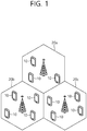
- FIG. 1 illustrates a wireless communication system
- the wireless communication system includes at least one base station (BS) 20.
- Each base station 20 provides a communication service to specific geographical areas (generally, referred to as cells) 20a, 20b, and 20c.
- the cell can be further divided into a plurality of areas (sectors).
- the UE generally belongs to one cell and the cell to which the UE belong is referred to as a serving cell.
- a base station that provides the communication service to the serving cell is referred to as a serving BS. Since the wireless communication system is a cellular system, another cell that neighbors to the serving cell is present. Another cell which neighbors to the serving cell is referred to a neighbor cell.
- a base station that provides the communication service to the neighbor cell is referred to as a neighbor BS.
- the serving cell and the neighbor cell are relatively decided based on the UE.
- a downlink means communication from the base station 20 to the UE1 10 and an uplink means communication from the UE 10 to the base station 20.
- a transmitter may be a part of the base station 20 and a receiver may be a part of the UE 10.
- the transmitter may be a part of the UE 10 and the receiver may be a part of the base station 20.
- the wireless communication system may be generally divided into a frequency division duplex (FDD) type and a time division duplex (TDD) type.
- FDD frequency division duplex
- TDD time division duplex
- uplink transmission and downlink transmission are achieved while occupying different frequency bands.
- the uplink transmission and the downlink transmission are achieved at different time while occupying the same frequency band.
- a channel response of the TDD type is substantially reciprocal. This means that a downlink channel response and an uplink channel response are approximately the same as each other in a given frequency area. Accordingly, in the TDD based wireless communication system, the downlink channel response may be acquired from the uplink channel response.
- the downlink transmission by the base station and the uplink transmission by the terminal may not be performed simultaneously.
- the uplink transmission and the downlink transmission are performed in different subframes.
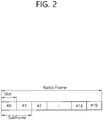
- FIG. 2 shows a downlink radio frame structure according to FDD of 3rd generation partnership project (3GPP) long term evolution (LTE).
- 3GPP 3rd generation partnership project
- LTE long term evolution
- the radio frame of FIG. 2 may be found in the section 5 of 3GPP TS 36.211 V10.4.0 (2011-12) "Evolved Universal Terrestrial Radio Access (E-UTRA); Physical Channels and Modulation (Release 10) ".
- the radio frame includes 10 sub-frames indexed 0 to 9.
- One sub-frame includes two consecutive slots. Accordingly, the radio frame includes 20 slots.
- the time taken for one sub-frame to be transmitted is denoted TTI (transmission time interval).
- TTI transmission time interval
- the length of one sub-frame may be 1ms
- the length of one slot may be 0.5ms.
- the structure of the radio frame is for exemplary purposes only, and thus the number of sub-frames included in the radio frame or the number of slots included in the sub-frame may change variously.
- one slot may include a plurality of OFDM symbols.
- the number of OFDM symbols included in one slot may vary depending on a cyclic prefix (CP).
- CP cyclic prefix
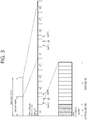
- Fig. 3 illustrates the architecture of a downlink radio frame according to TDD in 3GPP LTE.
- Sub-frames having index #1 and index #6 are denoted special sub-frames, and include a DwPTS(Downlink Pilot Time Slot: DwPTS), a GP(Guard Period) and an UpPTS(Uplink Pilot Time Slot).
- the DwPTS is used for initial cell search, synchronization, or channel estimation in a terminal.
- the UpPTS is used for channel estimation in the base station and for establishing uplink transmission sync of the terminal.
- the GP is a period for removing interference that arises on uplink due to a multi-path delay of a downlink signal between uplink and downlink.
- a DL (downlink) sub-frame and a UL (Uplink) co-exist in one radio frame.
- Table 1 shows an example of configuration of a radio frame.
- Table 1 UL-DL configuration Switch-point periodicity Subframe index 0 1 2 3 4 5 6 7 8 9 0 5 ms D S U U U D S U U U 1 5 ms D S U U D D S U U D 2 5 ms D S U D D D S U D D 3 10 ms D S U U U D D D D D D 4 10 ms D S U U D D D D D D 5 10 ms D S U D D D D D D D D 6 5 ms D S U U U U D S U U U D S U U D
- 'D' denotes a DL sub-frame
- 'U' a UL sub-frame
- 'S' a special sub-frame.
- FIG. 4 illustrates an example resource grid for one uplink or downlink slot in 3GPP LTE.
- the uplink slot includes a plurality of OFDM (orthogonal frequency division multiplexing) symbols in the time domain and NRB resource blocks (RBs) in the frequency domain.
- RBs resource blocks
- the number of resource blocks (RBs), i.e., NRB may be one from 6 to 110.
- the resource block is a unit of resource allocation and includes a plurality of sub-carriers in the frequency domain. For example, if one slot includes seven OFDM symbols in the time domain and the resource block includes 12 sub-carriers in the frequency domain, one resource block may include 7x12 resource elements (REs).
- REs resource elements
- the number of sub-carriers in one OFDM symbol may be one of 128, 256, 512, 1024, 1536, and 2048.
- the resource grid for one uplink slot shown in FIG. 4 may also apply to the resource grid for the downlink slot.
- FIG. 5 illustrates the architecture of a downlink sub-frame.
- one slot includes seven OFDM symbols, by way of example.
- the DL (downlink) sub-frame is split into a control region and a data region in the time domain.
- the control region includes up to first three OFDM symbols in the first slot of the sub-frame. However, the number of OFDM symbols included in the control region may be changed.
- a PDCCH (physical downlink control channel) and other control channels are assigned to the control region, and a PDSCH is assigned to the data region.
- the physical channels in 3GPP LTE may be classified into data channels such as PDSCH (physical downlink shared channel) and PUSCH (physical uplink shared channel) and control channels such as PDCCH (physical downlink control channel), PCFICH (physical control format indicator channel), PHICH (physical hybrid-ARQ indicator channel) and PUCCH (physical uplink control channel).
- data channels such as PDSCH (physical downlink shared channel) and PUSCH (physical uplink shared channel) and control channels
- PDCCH physical downlink control channel
- PCFICH physical control format indicator channel
- PHICH physical hybrid-ARQ indicator channel
- PUCCH physical uplink control channel
- the PCFICH transmitted in the first OFDM symbol of the sub-frame carries CIF (control format indicator) regarding the number (i.e., size of the control region) of OFDM symbols used for transmission of control channels in the sub-frame.
- the wireless device first receives the CIF on the PCFICH and then monitors the PDCCH.
- the PCFICH is transmitted through a fixed PCFICH resource in the sub-frame without using blind decoding.
- the PHICH carries an ACK (positive-acknowledgement)/NACK (negative-acknowledgement) signal for a UL HARQ (hybrid automatic repeat request).
- the ACK/NACK signal for UL (uplink) data on the PUSCH transmitted by the wireless device is sent on the PHICH.
- the PBCH (physical broadcast channel) is transmitted in the first four OFDM symbols in the second slot of the first sub-frame of the radio frame.
- the PBCH carries system information necessary for the wireless device to communicate with the base station, and the system information transmitted through the PBCH is denoted MIB (master information block).
- MIB master information block
- SIB system information block
- the PDCCH may carry activation of VoIP (voice over internet protocol) and a set of transmission power control commands for individual UEs in some UE group, resource allocation of an upper layer control message such as a random access response transmitted on the PDSCH, system information on DL-SCH, paging information on PCH, resource allocation information of UL-SCH (uplink shared channel), and resource allocation and transmission format of DL-SCH (downlink-shared channel).
- a plurality of PDCCHs may be sent in the control region, and the terminal may monitor the plurality of PDCCHs.
- the PDCCH is transmitted on one CCE (control channel element) or aggregation of some consecutive CCEs.
- the CCE is a logical allocation unit used for providing a coding rate per radio channel's state to the PDCCH.
- the CCE corresponds to a plurality of resource element groups. Depending on the relationship between the number of CCEs and coding rates provided by the CCEs, the format of the PDCCH and the possible number of PDCCHs are determined.
- the DCI may include resource allocation of the PDSCH (this is referred to as a DL grant), resource allocation of a PUSCH (this is referred to as a UL grant), a set of transmit power control commands for individual UEs in any UE group, and/or activation of a voice over Internet protocol (VoIP).
- DCI downlink control information
- the DCI may include resource allocation of the PDSCH (this is referred to as a DL grant), resource allocation of a PUSCH (this is referred to as a UL grant), a set of transmit power control commands for individual UEs in any UE group, and/or activation of a voice over Internet protocol (VoIP).
- VoIP voice over Internet protocol
- the base station determines a PDCCH format according to the DCI to be sent to the terminal and adds a CRC (cyclic redundancy check) to control information.
- the CRC is masked with a unique identifier (RNTI; radio network temporary identifier) depending on the owner or purpose of the PDCCH.
- RNTI unique identifier
- the terminal's unique identifier such as C-RNTI (cell-RNTI)
- a paging indicator for example, P-RNTI (paging-RNTI) may be masked to the CRC.
- SI-RNTI system information-RNTI
- RA-RNTI random access-RNTI
- blind decoding is used for detecting a PDCCH.
- the blind decoding is a scheme of identifying whether a PDCCH is its own control channel by demasking a desired identifier to the CRC (cyclic redundancy check) of a received PDCCH (this is referred to as candidate PDCCH) and checking a CRC error.
- the base station determines a PDCCH format according to the DCI to be sent to the wireless device, then adds a CRC to the DCI, and masks a unique identifier (this is referred to as RNTI (radio network temporary identifier) to the CRC depending on the owner or purpose of the PDCCH.
- RNTI radio network temporary identifier
- the DCI format and the search space which is to be monitored are determined according to the transmission mode of the PDSCH.
- the table below represents an example of the PDCCH monitoring in which the C-RNTI is setup.
- Transmission mode DCI format Search space Transmission mode of PDSCH according to PDCCH Transmission mode 1 DCI format 1A Public service and terminal specific Single antenna port, port 0 DCI format 1 Terminal specific Single antenna port, port 0 Transmission mode 2 DCI format 1A Public service and terminal specific Transmit diversity DCI format 1 Terminal specific Transmit diversity Transmission mode 3 DCI format 1A Public service and terminal specific Transmit diversity DCI format 2A Terminal specific CDD(Cyclic Delay Diversity) or transmit diversity Transmission mode 4 DCI format 1A Public service and terminal specific Transmit diversity DCI format 2 Terminal specific Closed-loop spatial multiplexing Transmission mode 5 DCI format 1A Public service and terminal specific Transmit diversity DCI format ID Terminal specific MU-MIMO(Multi-user Multiple Input Multiple Output) Transmission mode 6 DCI format 1A Public service and terminal specific Transmit diversity DCI format 1B Terminal specific Closed-loop spatial multiplexing Transmission mode 7 DCI format 1A Public service and terminal specific If the number of PBCH transmisison ports is 1, single antenna port, port 0.
- transmit Diversity MBSFN subframe port 7 as independent antenna port DCI format 2C Terminal specific 8 transmisison layers, ports 7-14 are used or port 7 or 8 is used as independent antenna port Transmission mode 10 DCI 1A Public service and terminal specific Non-MBSFN subframe: if the number of PBCH antenna ports is 1, port 0 is used as independent antenna port. Otherwise, transmit Diversity MBSFN subframe: port 7 as independent antenna port DCI format 2D Terminal specific 8 transmisison layers, ports 7-14 are used or port 7 or 8 is used as independent antenna port
- DCI format Contents DCI format 0 Used in PUSCH scheduling DCI format 1 Used in scheduling of one PDSCH codeword DCI format 1A Used in compact scheduling of one PDSCH codeword and random access process DCI format 1B Used in compact scheduling of one PDSCH codeword having precoding information DCI format 1C Used in very compact scheduling of one PDSCH codeword DCI format ID Used in precoding and compact scheduling of one PDSCH codeword having power offset information DCI format 2 Used in PDSCH scheduling of terminals configured in closed-loop spatial multiplexing mode DCI format 2A Used in PDSCH scheduling of terminals configured in open-loop spatial multiplexing mode DCI format 2B DCI format 2B is used for resouce allocation for dual-layer beam-forming of PDSCH.
- DCI format 2C DCI format 2C is used for resouce allocation for closed-loop SU-MIMO or MU-MIMO operation to 8 lavers.
- DCI format 2D DCI format 2C is used for resouce allocation to 8 lavers.
- DCI format 3 Used to transmit TPC command of PUCCH and PUSCH having 2 bit power adjustments
- DCI format 3A Used to transmit TPC command of PUCCH and PUSCH having 1 bit power adjustment
- DCI format 4 Used in PUSCH scheduling of uplink (UP) operated in multi-antenna port transmisison mode
- FIG. 6 illustrates a structure of an uplink subframe in 3GPP LTE.
- an uplink subframe may be divided into a control region and a data region in a frequency domain.
- the control region is allocated a PUCCH for transmission of uplink control information.
- the data region is allocated a PUSCH for transmission of data ( along with control information in some cases).
- a PUCCH for one UE is allocated a RB pair in a subframe.
- RBs in the RB pair take up different subcarriers in each of first and second slots.
- a frequency occupied by the RBs in the RB pair allocated to the PUCCH changes with respect to a slot boundary, which is described as the RB pair allocated to the PUCCH having been frequency-hopped on the slot boundary.
- a UE transmits uplink control information through different subcarriers according to time, thereby obtaining a frequency diversity gain.
- m is a location index indicating the logical frequency-domain location of an RB pair allocated for a PUCCH in a subframe.
- Uplink control information transmitted on a PUCCH may include a HARQ ACK/NACK, a channel quality indicator (CQI) indicating the state of a downlink channel, a scheduling request (SR) which is an uplink radio resource allocation request, or the like.
- CQI channel quality indicator
- SR scheduling request
- a PUSCH is mapped to a uplink shared channel (UL-SCH) as a transport channel.
- Uplink data transmitted on a PUSCH may be a transport block as a data block for a UL-SCH transmitted during a TTI.
- the transport block may be user information.
- the uplink data may be multiplexed data.
- the multiplexed data may be the transport block for the UL-SCH multiplexed with control information.
- control information multiplexed with data may include a CQI, a precoding matrix indicator (PMI), an HARQ, a rank indicator (RI), or the like.
- the uplink data may include only control information.
- a carrier aggregation system is described hereinafter.
- a carrier aggregation system aggregates a plurality of component carriers (CCs).
- CCs component carriers
- a conventional definition of a cell is changed according to carrier aggregation.
- a cell may denote a combination of a downlink component carrier and an uplink component carrier or a downlink component carrier alone.
- cells may be divided into a primary cell, a secondary cell, and a serving cell.
- a primary cell denotes a cell operating at a primary frequency, in which a UE performs an initial connection establishment procedure or a connection reestablishment procedure with a BS or which is designated as a primary cell in a handover procedure.
- a secondary cell denotes a cell operating at a secondary frequency, which is configured once RRC connection is established and is used to provide an additional radio resource.
- the carrier aggregation system may support a plurality of component carriers (CCs), that is, a plurality of serving cells, unlike a single carrier system.
- CCs component carriers
- the carrier aggregation system may support cross-carrier scheduling.
- Cross-carrier scheduling is a scheduling method for performing resource allocation for a PDSCH transmitted through a different component carrier through a PDCCH transmitted through a specific component carrier and/or resource allocation for a PUSCH transmitted through a component carrier different from a component carrier basically linked with the specific component carrier.
- synchronization with a cell is obtained through a synchronization signal (SS) in a cell search process.
- SS synchronization signal
- the synchronization signal is described in detail below with reference to FIG. 7 .
- FIG. 7 illustrates a frame structure for the transmission of a synchronization signal in an FDD frame.
- a slot number and a sub frame number starts with 0.
- UE may perform time and frequency synchronization based on a synchronization signal received from an eNodeB.
- a synchronization signal is used for cell search and may be divided into a primary synchronization signal (PSS) and a secondary synchronization signal (SSS).
- PSS primary synchronization signal
- SSS secondary synchronization signal
- 3GPP LTE-A for a synchronization signal, reference may be made to Paragraph 6.11 of 3GPP TS V10.2.0 (2011-06).
- a PSS is used to obtain OFDM symbol synchronization or slot synchronization and associated with a physical-layer cell identity (PCI). Furthermore, an SSS is used to obtain frame synchronization. Furthermore, an SSS is used to detect a CP length and to obtain a physical layer cell group ID.
- PCI physical-layer cell identity
- a synchronization signal may be transmitted in a subframe No. 0 and a subframe No. 5 several time by taking into consideration 4.6ms, that is, the length of a GSM (global system for mobile communication) frame in order to facilitate inter-RAT (radio access technology) measurement.
- the boundary of the frame may be detected through an SSS. More specifically, in an FDD system, a PSS is transmitted in the last OFDM symbol of a slot No. 1 or a slot No. 10, and an SSS is transmitted in an OFDM symbol right before a PSS.
- a synchronization signal may send any one of a total of 504 physical cell IDs through a combination of three PSSs and 168 SSSs.
- a PBCH (physical broadcast channel) is transmitted in the first 4 OFDM symbols of the first slot.
- a synchronization signal and PBCH are transmitted within center 6 RBs within a system bandwidth so that UE can detect or demodulate the synchronization signal regardless of a transmission bandwidth.
- a physical channel in which a PSS is transmitted is called a P-SCH
- a physical channel in which an SSS is transmitted is called an S-SCH.
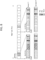
- FIG. 8 illustrates an example of a frame structure for sending a synchronization signal in a TDD frame.
- a PSS is transmitted in the third OFDM symbols of a third slot and thirteenth slot.
- An SSS is transmitted prior to three OFDM symbols in OFDM symbols in which a PSS is transmitted.
- a PBCH is transmitted in the first 4 OFDM symbols of a second slot in the first subframe.
- transmission information for example, data is easily distorted and changed while it is transmitted through a radio channel. Accordingly, a reference signal is required in order to demodulate such a transmission information without an error.
- the reference signal is a signal known to both a transmitter and a receiver and is transmitted along with transmission information. Since transmission information transmitted by a transmitter experiences a corresponding channel for each transmission antenna or layer, a reference signal may be allocated to each transmission antenna or layer. A reference signal for each transmission antenna or layer may be identified using resources, such as a frequency and code. A reference signal may be used for two purposes, that is, the demodulation and channel estimation of transmission information.
- a downlink reference signal may be divided into a cell-specific reference signal (CRS), an MBSFN (multimedia broadcast and multicast single frequency network) reference signal, a UE-specific reference signal (UE-specific RS, URS), a positioning reference signal (positioning RS, PRS), and a CSI reference signal (CSI-RS).
- CRS is a reference signal transmitted to all UEs within a cell and also called a common reference signal.
- the CRS may be used for the channel measurement of CQI feedback and the channel estimation of PDSCH.
- the MBSFN reference signal may be transmitted in a subframe allocated for MBSFN transmission.
- the URS is a reference signal received by a specific UE or specific UE group within a cell and may be called a demodulation reference signal (DM-RS).
- the DM-RS is chiefly used for a specific UE or specific UE group to perform data demodulation.
- the PRS may be used to estimate the location of UE.
- the CSI-RS is used for the channel estimation of the PDSCH of LTE-A UE.
- the CSI-RSs are deployed relatively sparsely in a frequency domain or time domain and may be punctured in the data region of a common subframe or MBSFN subframe.
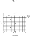
- FIG. 9 illustrates an example of a pattern in which CRSs are mapped to RBs if an eNodeB uses a single antenna port.
- R0 illustrates an RE to which a CRS transmitted by the antenna port number 0 of an eNodeB is mapped.
- the CRS is transmitted in all downlink subframes within a cell that supports PDSCH transmission.
- the CRS may be transmitted on antenna ports 0 to 3.
- a pseudo-random sequence r 1,ns (m) generated from a seed value based on a cell ID (identity) is subject to resource mapping as a complex-valued modulation symbol a (p) k,l .
- n s is a slot number within a single radio frame
- p is an antenna port
- l is an OFDM symbol number within the slot.
- K is a subcarrier index.
- l,k is represented as in the following equation.
- Equation 1 p denotes an antenna port, and n s denotes a slot number 0 or 1.
- N Cell ID a cell ID . Accordingly, cells having cell IDs 0, 6, 12, ..., that is, a multiple of 6, send CRSs in the same subcarrier location k.
- Equation 1 l is determined by the antenna port p, and may have a possible value of 0, 4, 7, or 11. Accordingly, the CRS is transmitted on an 0, 4, 7, 11 symbol.
- a resource element (RE) allocated to the CRS of a single antenna port may not be used to send another antenna port and needs to be configured to be zero. Furthermore, in an MBSFN (multicast-broadcast single frequency network) subframe, the CRS is transmitted only in a non-MBSFN region.
- MBSFN multicast-broadcast single frequency network
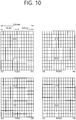
- FIG. 10 illustrates an example of RBs to which CSI-RSs are mapped in reference signals.
- a CSI-RS is used for channel measurement for the channel estimation and channel information of the PDSCH of LTE-A UE.
- CSI-RSs are deployed relatively sparsely in a frequency domain or time domain and may be punctured in the data region of a subframe or MBSFN subframe. If a CSI-RS is required to estimate a CSI, a CQI, PMI, and RI may be reported by UE.
- a CSI-RS is transmitted through a 1, 2, 4, or 8 antenna port.
- a CSI-RS reference may be made to Paragraph 6.10.5 of 3GPP (3rd Generation Partnership Project) TS 36.211 V10.1.0 (2011-03) "Technical Specification Group Radio Access Network; Evolved Universal Terrestrial Radio Access (E-UTRA); Physical channels and modulation (Release 8) .”
- a maximum of 32 different configurations may be proposed in order to reduce ICI (inter-cell interference) in a multi-cell environment including a heterogeneous network (HetNet) environment.
- a CSI-RS configuration is different depending on the number of antenna ports within a cell and a CP.
- a neighbor cell may have a different configuration to the greatest extent.
- a CSI-RS configuration may be divided into a case where it is applied to both an FDD frame and TDD frame and a case where it is applied to only a TDD frame depending on a frame structure.
- a plurality of CSI-RS configurations may be used.
- a zero or one CSI-RS configuration may be used for UE that assumes a non-zero power CSI-RS, and zero or some CSI-RS configurations may be used for UE that assumes a zero power CSI-RS.
- a CSI-RS configuration may be indicated by a high layer.
- a CSI-RS-Config IE (information element) transmitted through a high layer may indicate a CSI-RS configuration.
- the following table illustrates an example of a CSI-RS-Config IE.
- CSI-RS-Config-r10 SEQUENCE ⁇ csi-RS-r10 CHOICE ⁇ release NULL, setup SEQUENCE ⁇ antennaPortsCount-r10 ENUMERATED ⁇ an1, an2, an4, an8 ⁇ , resourceConfig-r10 INTEGER (0..31), subframeConfig-r10 INTEGER (0..154), p-C-r10 INTEGER (-8..15) ⁇ ⁇ OPTIONAL, -- Need ON zeroTxPowerCSI-RS-r10 CHOICE ⁇ release NULL, setup SEQUENCE ⁇ zeroTxPowerResourceConfigList-r10 BIT STRING (SIZE (16)), zeroTxPowerSubframeConfig-r10 INTEGER (0..154) ⁇ ⁇ OPTIONAL -- Need ON ⁇ -- ASN1STOP
- an "antennaPortsCount” field indicates the number of antenna ports used for the transmission of a CSI-RS.
- a “resourceConfig” field indicates a CSI-RS configuration.
- a “SubframeConfig” field and a “zeroTxPowerSubframeConfig” field indicate a subframe configuration in which a CSI-RS is transmitted.
- a "zeroTxPowerResourceConfigList” field indicates the configuration of a zero power CSI-RS.
- a CSI-RS configuration corresponding to bits configured to be 1 may be configured as a zero power CSI-RS.
- n s is a slot number within a radio frame, and 1 is an OFDM symbol number within the slot.
- c(i) is a pseudo random sequence and started from each OFDM symbol as c init indicated in Equation.
- N ID cell means a physical cell ID.
- a reference signal sequence r 1,ns (m) is mapped to a complex value modulation symbols a k,l (p) used as a reference symbol for an antenna port p.
- r 1,ns (m) and a k,l (p) may be represented as in the following equation.
- a k , l p w l " ⁇ r m
- k k ' + 12 m + ⁇ ⁇ 0 for p ⁇ 15,16
- normal cyclic prefix ⁇ 6 for p ⁇ 17,18 normal cyclic prefix ⁇ 1 for p ⁇ 19,20
- extended cyclic prefix l l ' + ⁇ l " CSIreference signal configurat ions 0 ⁇ 19 , normal cyclic prefix 2 l
- Equation 2 (k", l") and n s are given in Table 5 and Table 6 to be described later.
- a CSI-RS may be transmitted in a downlink slot in which (n s mod 2) satisfies the conditions of Table 5 and Table 6 (In this case, mod means modular operation. That is, (n s mod 2) means the remainder obtained by dividing n s by 2).
- the table 6 illustrates CSI-RS configurations in a normal CP and table 7 illustrates CSI-RS configuration in an extended CP.
- [Table 6] Number of configured CSI-RSs 1 or 2 4 8 CSI-RS configuration index (k',1') n s mod 2 (k',1') n s mod 2 (k',1') n s mod 2 TDD and FDD frame 0 (9,5) 0 (9,5) 0 (9,5) 0 9,5) 0 1 (11,2) 1 (11,2) 1 (11,2) 1 2 (9,2) 1 (9,2) 1 (9,2) 1 (9,2) 1 3 (7,2) 1 (7,2) 1 (7,2) 1 (4 (9,5) 1 (9,5) 1 (9,5) 1 9,5) 1 5 (8,5) 0 (8,5) 0 6 (10,2) 1 (10,2) 1 7 (8,2) 1 (8,2) 1 8 (6,2) 1 (6,2) 1 9 (8,5) 1 10 (3,5) 0 11 (2,5) 0 12 (5,2) 1 13 (4,2) 1 14
- UE may send a CSI-RS only in a downlink slot that satisfies the condition of ns mod 2. Furthermore, UE does not send a CSI-RS in a subframe in which the transmission of a special subframe, CSI-RS of a TDD frame collides against a synchronization signal, a PBCH (physical broadcast channel), and a system information block type 1 (SystemInformationBlockType1) or a subframe in which a paging message is transmitted.
- PBCH physical broadcast channel
- SystemInformationBlockType1 system information block type 1
- a resource element in which the CSI-RS of a single antenna port is transmitted is not used for the transmission of the CSI-RS of a PDSCH or another antenna port.
- CSI-RS-SubframeConfig I CSI-RS CSI-RS cycle T CSI-RS (subframe) CSI-RS subframe offset ⁇ CSI-RS (subframes) 0-4 5 I CSI-RS 5 - 14 10 I CSI-RS -5 15 - 34 20 I CSI-RS -15 35 - 74 40 I CSI-RS -35 75 - 154 80 I CSI-RS -75
- the cycle TCSI-RS and offset ⁇ CSI-RS of a subframe in which a CSI-RS is transmitted may be determined depending on a CSI-RS subframe configuration ICSI-RS.
- the CSI-RS subframe configuration may be any one of the "SubframeConfig" field and "ZeroTxPowerSubframeConfig" field of the CSI-RS-Config IE in the above table.
- the CSI-RS subframe configuration may be separately configured with respect to a non-zero power CSI-RS and a zero power CSI-RS.
- FIG. 10 illustrates resource elements used for CSI-RSs when a CSI-RS configuration index is 0 in a normal CP structure.
- Rp illustrates a resource element used for CSI-RS transmission on an antenna port p.
- a CSI-RS for antenna ports 15 and 16 is transmitted through resource elements corresponding to the third subcarrier (i.e., subcarrier index 2) of the sixth and the seventh OFDM symbols (i.e., OFDM symbol indices 5, 6) of a first slot.
- a CSI-RS for antenna ports 17 and 18 is transmitted through resource elements corresponding to the ninth subcarrier (i.e., subcarrier index 8) of the sixth and the seventh OFDM symbols (OFDM symbols indices 5, 6) of the first slot.
- a CSI-RS for antenna ports 19 and 20 is transmitted through the same resource elements as those in which the CSI-RS for the antenna ports 15 and 16 is transmitted.
- a CSI-RS for the antenna ports 21 and 22 is transmitted through the same resource elements as those in which the CSI-RS for the antenna ports 17 and 18 are transmitted.
- the UE may receive an RB to which R15 to R22 has been mapped. That is, the UE may receive a CSI-RS having a specific pattern.
- a small cell of which a cell coverage radius is small is added in the coverage of a legacy cell and that the small cell handles a greater amount of traffic.
- the legacy cell has a greater coverage than that of the small cell, and thus is also referred to as a macro cell.
- FIG. 11 illustrates a heterogeneous network environment in which a macro cell and a small cell co-exist and which is possibly used in a next-generation wireless communication system.
- FIG. 11 it is shown a heterogeneous network environment in which a macro cell served by a legacy eNodeB 200 overlaps with a small cell served by one or more small eNodeBs 300a, 300b, 300c, and 300d.
- the legacy eNodeB provides a greater coverage than the small eNodeB, and thus is also called a macro eNodeB (MeNB).
- MeNB macro eNodeB
- the macro cell and the MeNB may be used together.
- a UE having access to the macro cell 200 may be referred to as a macro UE.
- the macro UE receives a downlink signal from the MeNB, and transmits an uplink signal to the MeNB.
- coverage holes of the macro cell can be filled by configuring the macro cell as a primary cell (Pcell) and by configuring the small cell as a secondary cell (Scell).
- Pcell primary cell
- Scell secondary cell
- overall performance can be boosted by configuring the small cell as the Pcell and by configuring the macro cell as the Scell.
- a coverage size of the small cell may be decreased according to a situation.
- the small cell may be off and then on again according to the situation.
- FIG. 12 illustrates an example of a situation in which a small cell is densely deployed.
- FIG. 12 it is shown a situation in which a small cell is densely deployed in the coverage of a macro cell.
- a UE 100 may have difficulty to detect the small cells within a short time.
- the aforementioned cell detection is performed through PSS/SSS reception.
- the UE 100 may have difficult to entirely receive it at once.
- mutual interference occurs, which may cause difficulty for the UE 100 to receive it correctly.
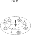
- FIG. 13 illustrates an example of transmitting a discovery signal by a small cell according to a disclosure of the present specification.
- one disclosure of the present specification proposes to transmit a new discovery signal (DS) in addition to the legacy PSS/SSS by a small cell so that a UE can effectively detect the small cells.
- the DS may also be called a discovery reference signal (DRS). Accordingly, the UE must perform a cell search procedure or a cell detection procedure by using the DS in addition to the legacy PSS/SSS.
- DRS discovery reference signal
- the DS may imply a signal periodically transmitted with a long period.
- the DS may also be transmitted by not only a small cell but also a remote radio head (RRH), a transmission point (TP), etc.
- RRH remote radio head
- TP transmission point
- the DS may have the following feature.
- the DS may be implemented with the following signals.
- the DS may be used for coarse time/frequency tracking and measuring.
- the DS must satisfy the following requirements.
- a period of the DS is determined by considering the following constraints.
- the CRS and the CSI-RS may be called respectively a DS-CRS (or DRS-CRS) and a DS-CSI-RS (or DRS-CSI-RS).
- the PRS may be called a DS-PRS (or DRS-PRS).
- a sequence and resource of the DRS-PSS and the DRS-SSS may be configured as similar as possible to the legacy PSS and the SSS.
- a difference with the legacy PSS/SSS may lie in that it is transmitted on a different scrambling initial parameter and/or resource location (e.g., different frequency/time resources).
- Respective signals constituting the discovery signal may be all transmitted according to the same transmission period/offset.
- respective components may be transmitted according to different transmission periods/offsets. For example, this will be described with reference to FIG. 14 .
- FIG. 14 illustrates an exemplary period of a discovery signal transmitted according to a disclosure of the present specification.
- the DRS-PSS when the discovery signal includes a DRS-PSS(and/or DRS-SSS) and a DRS-CSI-RS, the DRS-PSS (and/or DRS-SSS) may be transmitted for example with a period of 40msec, whereas the DRS-CSI-RS may be transmitted with a period of 80msec.
- the DRS-PSS and the DRS-SSS may be both transmitted, or 2) only the DRS-PSS may be transmitted, or 3) only the DRS-SSS may be transmitted.
- the description of the present invention is also applicable to all of the above three cases.
- a small cell may transmit a discovery signal both in an ON state and an OFF state. Due to transmission of a channel/signal or the like, a location of an OFDM symbol capable of transmitting a DRS-PSS and a DRS-SSS in the ON state is relatively restricted in comparison with a location of an OFDM symbol capable of performing transmission in an OFF state.
- the following description is applicable to both a case where only the DRS-PSS or the DRS-SSS is transmitted between the DRS-PSS and the DRS-SSS or a case where both of the DRS-PSS and the DRS-SSS are transmitted. In addition, it is also applicable to all cases where the DRS-PSS and/or DRS-PSS to be transmitted on multiple OFDM symbols are plural in number.
- a DRS-PSS may be transmitted on the same OFDM symbol location as the legacy PSS and the legacy SSS.
- the DRS-PSS (or DRS-SSS) must be transmitted by using the same RE source and sequence as the legacy PSS (or legacy SSS).
- the legacy UE recognizes this as the legacy PSS (legacy SSS).
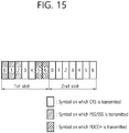
- Transmission locations of a DRS-PSS and a DRS-SSS may be determined by considering transmission locations of a PDCCH, a PSS, an SSS, a CRS, and a PBCH. More specifically, this will be described with reference to FIG. 15 .
- the transmission locations of the DRS-PSS and the DRS-SSS may be determined by considering transmission locations of a PDCCH, a PSS, an SSS, and a CRS and an OFDM symbol location of a PBCH transmitted on OFDM symbols #0, #1, #2, and #3 in a second slot.
- an OFDM symbol #3 in a first slot and OFDM symbols #5 and #6 in the second slot may be determined as a symbol capable of transmitting the DRS-PSS and the DRS-SSS.
- transmission locations of the DRS-PSS and the DRS-SSS may be determined by considering transmission locations of a PDCCH, a PSS, an SSS, and a DRS as shown in FIG. 15 .
- an OFDM symbol #3 in a first slot and OFDM symbols #2, #3, #5, and #6 in a second slot may be considered as a symbol capable of transmitting the DRS-PSS and the DRS-SSS.
- transmission locations of the DRS-PSS and the DRS-SSS may be determined by considering transmission locations of PDCCH and CRS.
- OFDM symbols #3, #5, and #6 in a first slot and OFDM symbols #2, #3, #5, and #6 in a second slot may be considered as a symbol capable of transmitting the DRS-PSS and the DRS-SSS.
- an OFDM symbol for transmitting a CSI-RS may be additionally considered.
- a location of an OFDM symbol capable of transmitting the CSI-RS may be considered in addition to the OFDM symbol capable of transmitting the DRS-PSS and DRS-SSS considered in the above options 1, 2, 3, and 4.
- a location of an OFDM symbol capable of transmitting the CSI-RS is OFDM symbols #5 and #6 in a first slot and OFDM symbols #2, #3, #5, and #6 in a second slot in case of FDD, and is OFDM symbols #5 and #6 in a first slot and OFDM symbols #1, #2, #3, #5, and #6 in a second slot in case of TDD. Therefore, the DRS-PSS and the DRS-SSS may be transmitted through an OFDM symbol location by excluding the location of the OFDM symbol capable of transmitting the CSI-RS from the OFDM symbol locations considered in the options 1 to 4.
- the location of the OFDM symbol capable of transmitting the CSI-RS is excluded, there may be a problem in that the number of symbols capable of transmitting the DRS-PSS and the DRS-SSS is insufficient.
- a transmission location of the PDCCH, the PSS, the SSS, the CRS, and the PBCH and a transmission location of the CSI-RS are considered in an FDD system, only an OFDM symbol #3 in a first slot is a symbol location that can be used to transmit the DRS-PSS and the DRS-SSS.
- the number of OFDM symbols capable of transmitting the DRS-PSS and the DRS-SSS is insufficient.
- the number of OFDM symbols capable of transmitting the PDCCH may be restricted. For example, it may be restricted that the PDCCH is transmitted through maximum one OFDM symbol or maximum two OFDM symbols on a subframe for transmitting the DRS-PSS and the DRS-SSS. Accordingly, the number of OFDM symbols capable of transmitting the DRS-PSS and the DRS-SSS may be increased.
- the UE may perform the following operation.
- the UE may first transmit the DRS-PSS and the DRS-SSS. For this, as to an overlapping RE region among transmission regions of the PDCCH and the DRS-PSS and DRS-SSS, the UE may assume that the PDCCH is punctured and the DRS-PSS and the DRS-SSS are transmitted.
- the UE may decide that a value received from the PCFICH has an error. That is, it may be decided that an error occurs in PCFICH reception, and reception of the DRS-PSS and the DRS-SSS may be performed in a region in which the OFDM symbol region for transmitting the PDCCH overlaps with the transmission region of the DRS-PSS and the DRS-SSS.
- the UE may assume that the DRS-PSS and the DRS-SSS are not transmitted in a corresponding subframe or in a corresponding OFDM symbol. That is, it may be decided that the PCFICH is correctly detected and it may be regarded that the PDCCH will be transmitted in a corresponding OFDM symbol region, and thus reception of the DRS-PSS and the DRS-SSS may not be performed in a corresponding subframe or a corresponding OFDM symbol.
- a DRS-PSS and/or a DRS-SSS may be transmitted through an OFDM symbol location determined as described above. If the DRS-PSS and the DRS-SSS are both transmitted, the DRS-PSS and the DRS-SSS may be both transmitted on a new location at which the legacy PSS and the legacy SSS are not transmitted, or only the DRS-PSS (or on the contrary, DRS-SSS) may be transmitted on a new OFDM symbol location described in the above section I and the DRS-SSS (or on the contrary, DRS-PSS) may be transmitted on an OFDM symbol location at which the legacy SSS (legacy PSS) is transmitted.
- the DRS-PSS (or on the contrary, DRS-SSS) may be transmitted on a new OFDM symbol location described above, or may be transmitted on an OFDM symbol location at which the legacy PSS (legacy SSS) is transmitted.
- DRS-SSS DRS-PSS
- DRS-PSS may be transmitted as a discovery signal between the DRS-PSS and the DRS-SSS, and the DRS-PSS (or on the contrary, DRS-SSS) may be transmitted on a new OFDM symbol mentioned in the above section I.
- a DRS-PSS (or DRS-SSS) of a specific cell may be transmitted on one of new OFDM symbol locations mentioned in the above section I.
- the DRS-PSS (or DRS-SSS) may be transmitted on a different OFDM symbol location in each cell.
- an OFDM symbol location on which the DRS-PSS (DRS-SSS) is transmitted may be determined by N ID (1) and/or N ID (2) or a cell ID of a cell for transmitting the DRS-PSS (or DRS-SSS).
- the DRS-PSS and the DRS-SSS may be transmitted on a new OFDM symbol location mentioned in the above section I.
- a DRS-PSS and DRS-SSS of a specific cell may be transmitted through one of new OFDM symbol locations mentioned in the above section I.
- the DRS-PSS and the DRS-SSS may be transmitted on a different OFDM symbol location in each cell.
- the OFDM symbol location on which the DRS-PSS and the DRS-SSS are transmitted may be determined by N ID (1) and/or N ID (2) or a cell ID of a cell for transmitting the DRS-PSS and the DRS-SSS transmitted on the different OFDM symbol location in each cell.
- a DRS-SSS and a DRS-SSS may be both transmitted as a discovery signal, whereas only the DRS-PSS (or DRS-SSS) may be transmitted on a new OFDM symbol location mentioned in the above section I and the DRS-SSS (or DRS-PSS) may be transmitted on an OFDM symbol location on which the legacy SSS (or legacy PSS) is transmitted.
- the location of the OFDM symbol on which the DRS-SSS (or DRS-PSS) is transmitted may be determined by N ID (1) and/or N ID (2) or a cell ID of a cell for transmitting the DRS-PSS and the DRS-SSS to decrease an influence of interference having an effect on the DRS-SSS (or DRS-PSS) by another cell.
- an OFDM symbol location of the DRS-PSS (DRS-SSS) is the same as the location of the legacy PSS (or legacy SSS)
- the OFDM symbol location of the DRS-SSS (or DRS-PSS) may be determined by N ID (2) .
- an OFDM symbol region for transmitting a DRS-SSS (or DRS-PSS) in a specific cell may be determined for example as follows.
- a location of an OFDM symbol for transmitting a DRS-SSS (or DRS-PSS) of a specific cell may be determined by N ID (2) .
- the DRS-SSS (or DRS-PSS) may be transmitted on an OFDM symbol #1 in a second slot if a value of N ID (2) mod 3 is 0, an OFDM symbol #2 of the second slot if a value of N ID (2) mod 3 is 1, and an OFDM symbol #3 of the second slot if a value of N ID (2) mod 3 is 2.
- a transmission method applicable to a case where the DRS-PSS and the DRS-SSS are both transmitted is also applicable to a case where multiple DRS-PSSs are transmitted.
- the two DRS-PSSs are transmitted as a discovery signal and the two DRS-PSSs are respectively a DRS-PSS-1 and a DRS-PSS-2
- a location at which the DRS-PSS is transmitted may be regarded as a location at which the DRS-PSS-1 is transmitted
- a location at which the DRS-SSS is transmitted may be regarded as a location at which the DRS-PSS-2 is transmitted.
- a small cell shared cell identification (ID) scenario environment is described to which disclosures of the present specification will be described hereinafter.
- 'base station' is used hereinafter as an inclusive term including a remote radio head (RRH), an eNB, a transmission point (TP), a reception point (RP), a relay, etc.
- RRH remote radio head
- TP transmission point
- RP reception point
- relay a relay
- DRS-PSS, DRS-SSS, DRS-CRS, DRS-CSI-RS, and DRS-PRS may respectively imply PSS, SSS, CRS, CSI-RS, and PRS constituting a discovery signal.
- a sequence and resource of DRS-PSS and DRS-SSS are configured as similar as possible to legacy PSS and SSS, and a difference with legacy PSS/SSS may lie in that it is transmitted on a different scrambling initial parameter(s) and/or resource location (e.g., different frequency/time resources).
- FIG. 16 illustrates an example of a small cell shared cell ID scenario environment.
- a "small cell shared cell-ID scenario” may imply a scenario in which multiple transmission points (TPs) in a specific (small cell) cluster/group perform transmission with the same physical cell-ID (PCID).
- TPs transmission points
- PCID physical cell-ID
- the PCID may imply a cell-specific ID used for PSS/SSS and CRS transmission similarly to the current LTE technique, or may be a separate cluster ID commonly used in a specific cluster.
- Unique identification information may be assigned for each TP to obtain a cell-splitting gain among the multiple TPs in the cluster, and this may be named as a TPID.
- each TPID may be used as a sequence scrambling initialization parameter (e.g., scramblingIdentity) of a reference signal (RS) for one of a discovery signal and CSI-RS transmitted from a corresponding TP, and may also be used for other TP-specific RS transmissions.
- RS reference signal
- a physical-layer cell identity N ID cell 3 N ID 1 + N ID 2 is thus uniquely defined by a N ID 1 in the range of 0 to 167, representing the physical-layer cell-identity group, and a number N ID 2 in the range of 0 to 2, representing the physical-layer identity within the physical-layer cell-identity group.
- the UE may receive DRS-PSS and DRS-SSS to acquire a PCID of each cell (TP). More specifically, the UE may detect the DRS-PSS to acquire N ID 2 , and may detect the DRS-SSS to acquire N ID 1 .
- N ID CSI used to generate a DRS-CSI-RS is called a DRS-CSI-RS scrambling ID. That is, the DRS-CSI-RS scrambling ID may refer to N ID CSI used to generate a CSI-RS sequence in the content of TS 36.211 described below.
- the pseudo-random sequence c(i ) is defined in Section 7.2.
- N ID CSI equals N ID cell unless configured by higher layers.
- the DRS-CSI-RS scrambling ID is a sequence scrambling initialization parameter, and may imply scramblingIdentity-r11 constituting CSI-RSConfigNZP IE(Information Element) in the content of TS 36.331 described below.
- the DRS-CSI-RS RE config implies a CSI reference signal configuration defined in Table 6.10.5.2-1, 6.10.5.2-2 of TS 36.211. That is, the DRS-CSI-RS RE config may imply resourceConfig-r11 constituting CSI-RSConfigNZP IE in TS 36.331.
- each TP transmits a TP-specific discovery RS (DRS).
- the DRS may consist of several RSs, and it is not assumed that each TP transmits several RSs.
- the DRS consists of DRS-PSS/DRS-SSS/DRS-CSI-RS/DRS-CRS
- the DRS-PSS/DRS-SSS/DRS-CRS may be transmitted in each TP or may be transmitted in representative TPs.
- the DRS-CSI-RS is included in the DRS transmitted by each TP for convenience of explanation, the present invention is not limited thereto (Other different TP-specific DRSs may be defined and used.
- TPs may be detected through DRS-CRS transmission in each TP.
- a value v-shift for transmitting the CRS may be used by being mapped to a TP scrambling ID.).
- the DRS-CSI-RS may be transmitted by using a different scrambling sequence initialization parameter and/or RE location for each TP.
- the present invention proposes a method of configuring a DRS-CSI-RS, and elements required when a UE detects the DRS-CSI-RS.
- proposed methods are described in the present invention by focusing on transmission of the DRS-CSI-RS, it is apparent that ideas of the present invention are also applicable to an RS element constituting a different discovery signal such as DRS-CRS, DRS-PRS, or the like and to a discovery signal having a different form.
- a UE may receive from an eNodeB a DRS measurement timing configuration (i.e., DMTC) which is timing information for a DRS measurement.
- the DRS measurement timing configuration may include a period and an offset value, and in addition, may also include a duration value.
- a resource and resource configuration (DRS-CSI-RS RE config) in which the DRS-CSI-RS is transmitted may follow the conventional resource and resource configuration in which a CSI-RS can be transmitted, or may be newly defined.
- a resource configuration table is called a DRS-CSI-RS resource configuration table.
- the present invention describes a DRS-CSI-RS transmission method based on the configuration table.
- a scrambling identity used in the DRS-CSI-RS may be different from a scrambling identity used in the CSI-RS, a range value thereof may be limited to [0 ... 503].
- the present invention describes a method in which the scrambling identity used in the DRS-CSI-RS is recognized by a terminal, and this will be described by roughly dividing into an implicit mechanism and an explicit mechanism.
- the scrambling identity may be based on a resource configuration table or resource by which a DRS-CSI-RS or information known to the terminal can be transmitted.
- the terminal must perform blind detection (BD) on [0 ... 503] scrambling IDs for a corresponding resource, and thus a complexity of the terminal is significantly increased in proportion to the number of DRS-CSI-RS locations. Therefore, it can be said that the present invention aims to limit the number of scrambling IDs to be searched by the terminal in each resource in order to allocate many orthogonal resources while not increasing BD complexity of the terminal.
- BD blind detection
- the disclosures of the present specification propose a method of configuring a DRS-CSI-RS when a CSI-RS (e.g., a DRS-CSI-RS) is used for a discovery signal in a small cell shared cell ID scenario environment.
- a CSI-RS e.g., a DRS-CSI-RS
- a disclosure of the present specification proposes a method of determining a scrambling ID of a discovery signal through an implicit mechanism.
- the first disclosure of the present specification proposes a method of determining a scrambling ID of a discovery signal through an implied or implicit mechanism, and a method of detecting the discovery signal by using the determined scrambling ID.
- the first disclosure of the present specification describes a DRS-CSI-RS for a case where the discovery signal has a form of CSI-RS (or is a CSI-RS based signal), it is apparent to those ordinarily skilled in the art that the first disclosure of the present specification is also applicable to a case where the discovery signal has other forms.
- the method may include: determining a scrambling identifier of the discovery signal for each of the multiple TPs on the basis of the PCID which is commonly used by the multiple TPs and a resource elements (RE) of each of discovery 32 signals transmitted from the respective multiple TPs; demodulating the discovery signal on each position of the RE by using the determined scrambling identifier to detect the discovery signal.
- PCID physical cell identifier
- the determining of the scrambling identifier for each of the multiple TPs may be achieved on the basis of the PCID and a resource configuration for the RE of each discovery signal.
- the discovery signal may be a signal based on one or more of a cell-specific reference signal (CRS), a channel-state information reference signal (CSI-RS), a primary synchronization signal (PSS), and a secondary synchronization signal (SSS).
- CRS cell-specific reference signal
- CSI-RS channel-state information reference signal
- PSS primary synchronization signal
- SSS secondary synchronization signal
- the resource configuration for the discovery signal is resourceConfig-r11 which is a CSI reference signal configuration constituting a CSI-RS-ConfigNZP information element (IE).
- the scrambling identifier may be scramblingIdentity-r11 constituting an SI-RS-ConfigNZP IE.
- the scrambling identifier may be determined on the basis of the PCID, a resource configuration for the RE of each discovery signal, and an offset.
- the offset may be configured through higher layer signaling.
- the offset may be configured differently for each PCID.
- the offset may be a value corresponding to a difference between a subframe position at which transmission of the discovery signal starts and a subframe position at which the discovery signal is transmitted.
- the offset may be determined on the basis of a subframe index.
- FIG. 17 is a flowchart showing a method of detecting a discovery signal according to a first disclosure of the present specification.
- a method of detecting a discovery signal is a method of detecting a discovery signal from multiple transmission points (TPs) using the same physical cell identifier (PCID), and may be achieved in the following steps.
- a terminal may determine a scrambling identifier of the discovery signal for each of the multiple TPs on the basis of the PCID which is commonly used by the multiple TPs and a resource element (RE) of each of the discovery signals transmitted from the respective multiple TPs (S110).
- PCID which is commonly used by the multiple TPs
- RE resource element
- the terminal may demodulate the discovery signal on each position of the RE by using the determined scrambling identifier to detect the discovery signal (S120).
- Determining method A-1 Determining based on PCID and DRS-CSI-RS RE config
- the determining method A-1 is a scheme for decreasing a complexity and overhead required when a user equipment (UE) or a terminal detects DRS-CSI-RS and for decreasing a load when an eNodeB has to perform an excessively great amount of configurations to the terminal, and relates to a method of determining a CSI-RS scrambling ID according to a PCID and a DRS-CSI-RS RE config which is a resource element configuration of the DRS-CSI-RS as follows.
- a DRS-CSI-RS scrambling ID of DRS-CSI-RS of a specific transmission point (TP) may be determined according to the PCID and the DRS-CSI-RS RE config. That is, the DRS-CSI-RS scrambling ID of the DRS-CSI-RS may differ depending on the PCID and the DRS-CSI-RS RE config.
- the DRS-CSI-RS scrambling ID may be equal to '(PCID + DRS-CSI-RS RE config + offset) mod 504'.
- a terminal is not configured separately with the DRS-CSI-RS scrambling ID.
- the scrambling ID may be configured according to a physical cell ID detected from the DRS-PSS and the DRS-SSS (or DRS-CRS), a location of a resource element (RE) in which the DRS-CSI-RS is transmitted, or a DRS-CSI-RS RE config.
- a configuration of an RE in which the DRS-CSI-RS can be transmitted may correspond to a "(x+PCID+offset1) mod 20"-th resource in the resource configuration table.
- the DRS-CSI-RS when the DRS-CSI-RS is transmitted in the same subframe as the DRS-PSS and the DRS-SSS and when the DRS-PSS and the DRS-SSS are transmitted through the same RE location as the legacy PSS and the legacy SSS, the DRS-CSI-RS cannot be transmitted in OFDM symbols #5 and #6 of a first slot in which the DRS-PSS and the DRS-SSS can be transmitted.
- CP normal cyclic prefix
- the DRS-CSI-RS RE config of the DRS-CSI-RS may be limited only to the remaining DRS-CSI-RS RE configs other than the DRS-CSI-RE config transmitted through the OFDM symbols #5 and #6 of the first slot (e.g., CSI-RS reference signal configurations 0, 5, 10, and 11).
- an offset value may be as follows.
- the aforementioned eNodeB may be an eNodeB for managing/controlling a primary cell (PCell) of the terminal, an eNodeB for managing/controlling a serving cell of the terminal, or an eNodeB for transmitting assistant information to the terminal.
- PCell primary cell
- eNodeB for managing/controlling a serving cell of the terminal
- eNodeB for transmitting assistant information to the terminal.
- the first disclosure of the present specification may be applied only in a shared cell-ID scenario.
- the DRS-CSI-RS scrambling ID may be equal to a PCID.
- the DRS-CSI-RS scrambling ID may be equal to (PCID + DRS-CSI-RS RE config + offset) mod 504, whereas in the non-shared cell-ID scenario, the offset value maybe equal to -1 ⁇ CSI-RS RE config.
- the DRS-CSI-RS scrambling ID may be equal to ([504/N] x DRS-CSI-RS RE config + PCID + offset) mod 504'.
- N is the total number of DRS-CSI-RS RE configs.
- the terminal is not configured separately with the DRS-CSI-RS scrambling ID.
- the scrambling ID may be configured according to a physical cell ID detected from the DRS-PSS and the DRS-SSS (or DRS-CRS), a location of a resource element (RE) in which the DRS-CSI-RS is transmitted, or a DRS-CSI-RS RE config.
- an offset value may be as follows.
- the aforementioned eNodeB may be an eNodeB for managing/controlling a PCell of the terminal, an eNodeB for managing/controlling a serving cell of the terminal, or an eNodeB for transmitting assistant information to the terminal.
- Determining method A-2 Determining based on PCID
- the range of the DRS-CSI-RS scrambling ID to be searched by the terminal is configured according to a PCID (or N ID (1) and/or N ID (2) ).
- a range of an available DRS-CSI-RS scrambling ID may be pre-defined in a form of a table or an equation according to a PCID value of a specific TP (or cell).
- the range of the available DRS-CSI-RS scrambling ID in the specific TP may be equal to ⁇ (504/M)x(PCID mod M), (504/M)x(PCID mod M)+1, (504/M)x(PCID mod M)+2, ..., (504/M)x(PCID mod M)+M-1 ⁇ .
- the terminal is not configured separately with the DRS-CSI-RS scrambling ID.
- the scrambling ID may be configured according to a physical cell ID detected from the DRS-PSS and the DRS-SSS (or DRS-CRS).
- a value M may be the number of DRS-CRI-RS RE configs.
- a normal CP when a normal CP is used, it may be configured to 20 in case of FDD, and may be configured to 32 in case of TDD.
- an extended CP when an extended CP is used, it may be configured to 16 in case of FDD, and may be configured to 28 in case of TDD.
- the value M may always be configured to 32 irrespective of the normal/extended CP and the FDD/TDD.
- the determining method A-2 may be applied only in the shared cell-ID scenario.
- the DRS-CSI-RS scrambling ID may be equal to the PCID.
- A-3 Determining based on PCID, DRS-CSI-RS RE config, and subframe index
- a scrambling ID of a DRS-CS-RS transmitted in a specific TP may be determined according to a PCID and/or a DRS-CSI-RS RE config and a timing index (e.g., a subframe index).
- a scrambling ID of the DRS-CSI-RS may vary depending on a timing at which the DRS-CSI-RS is transmitted.
- a timing index may be as follows.
- the first method suggests that whether a shared cell-ID scenario is used or a non-shared cell-ID scenario is used at a corresponding frequency is configured to a terminal through higher layer signaling for each frequency.
- the first method suggests to report whether a corresponding measurement object uses a shared cell-ID scenario or a non-shared cell-ID scenario for each measurement object defined in TS 36.331.
- MeasObjectEUTRA information regarding whether a corresponding measurement object uses the shared cell-ID scenario or the non-shared cell-ID scenario may be included in MeasObjectEUTRA described below.
- Second method Indication of RSRP/RSRQ measurement RS
- the second method suggests that, in order for a terminal to determine how to configure a DRS-CSI-RS scrambling ID, an eNodeB indicates a reference signal (RS) to the terminal to perform RSRP/RSRQ measurement through higher layer signaling.
- RS reference signal
- the second method suggests that the eNodeB reports whether the RSRP/RSRQ measurement will be performed using a DRS-CRS (or CRS) or using a DRS-CSI-RS (or CSI-RS) to the terminal through the higher layer signaling.
- the terminal may determine whether an operation to be performed is based on a non-shared cell-ID operation or a shared cell-ID operation.
- the terminal may interpret this as that the operation to be performed is based on the non-shared cell-ID operation.
- the terminal may assume that the DRS-CSI-RS scrambling ID is equal to a PCID.
- the terminal may interpret this as that the operation to be performed is based on the non-shared cell-ID operation.
- the terminal may assume that the DRS-CSI-RS scrambling ID is determined through the implied or implicit mechanism mentioned above in the first and second disclosures of the present specification.
- the terminal may assume that the DRS-CSI-RS scrambling ID is equal to (PCID + DRS-CSI-RS RE config + offset) mod 504.
- An indication which plays a role of reporting whether the DRS-CRS (or CRS) will be used or the DRS-CSI-RS (or CSI-RS) will be used to perform the aforementioned RSRP/RSRQ measurement may be configured for each frequency through a higher layer.
- the indication which plays a role of reporting whether the DRS-CRS (or CRS) will be used or the DRS-CSI-RS (or CSI-RS) will be used to perform the RSRP/RSRQ measurement may be included in MeasObj ectEUTRA.
- the aforementioned method may be applied when the DRS is configurable with the PSS/SSS/CSI-RS/CRS or the PSS/SSS/CRS or when the DRS is configurable with the PSS/SSS/CSI-RS/CRS or the PSS/SSS/CSI-RS.
- the third method suggests that, in order for a terminal to determine how to configure a DRS-CSI-RS scrambling ID, an eNodeB reports to a terminal through higher layer signaling whether the DRS-CSI-RS scrambling ID is: a) equal to a PCID; or b) determined through an implicit or explicit configuration mechanism based on the aforementioned first and second disclosures of the present specification
- the eNodeB when it is said that the eNodeB reports to the terminal through higher layer signaling that the DRS-CSI-RS scrambling ID is determined through the implicit or explicit configuration mechanism based on the aforementioned first and second disclosures of the present specification, it may mean that the eNodeB reports, for example, that the DRS-CSI-RS scrambling ID is equal to (PCID + DRS-CSI-RS RE config + offset) mod 504.
- An indication reporting whether the aforementioned DRS-CSI-RS scrambling ID is: a) equal to the PCID; or b) determined through the implicit or explicit mechanism based on the first and second disclosures of the aforementioned present specification may be configured for each frequency through a higher layer.
- an indication indicating whether the DRS-CSI-RS scrambling ID is: a) equal to the PCID; or b) determined through the implicit or explicit mechanism based on the first and second disclosures of the aforementioned present specification may be included in MeasObjectEUTRA.
- the terminal may determine that the offset value of the DRS-CSI-RS scrambling ID is equal to -1 ⁇ CSI-RS RE config (i.e., the DRS-CSI-RS scrambling ID is equal to the PCID), and thus may interpret this as that an operation to be performed is based on a non-shared cell-ID operation.
- the terminal may acquire the DRS-CSI-RS scrambling ID based on the PCID and the DRS-CSI-RS RE config by using the offset value configured from the higher layer, and may interpret this as that the operation to be performed is based on a shared cell-ID operation.
- the aforementioned configuration/indication may be configured for each frequency through a higher layer.
- the indication may be configured for each cell ID or for each cell ID list through the higher layer.
- the indication may be configured for each measurement object defined in TS 36.331.
- An eNodeB 200 includes a processor 201, a memory 202, and a radio frequency (RF) unit 203.
- the memory 202 is coupled to the processor 201, and stores a variety of information for driving the processor 201.
- the RF unit 203 is coupled to the processor 201, and transmits and/or receives a radio signal.
- the processor 201 implements the proposed functions, procedures, and/or methods. In the aforementioned embodiment, an operation of the eNodeB may be implemented by the processor 201.
- An MTC device 100 includes a processor 101, a memory 102, and an RF unit 103.
- the memory 102 is coupled to the processor 101, and stores a variety of information for driving the processor 101.
- the RF unit 103 is coupled to the processor 101, and transmits and/or receives a radio signal.
- the processor 101 implements the proposed functions, procedures, and/or methods.
- the processor may include Application-specific Integrated Circuits (ASICs), other chipsets, logic circuits, and/or data processors.
- the memory may include Read-Only Memory (ROM), Random Access Memory (RAM), flash memory, memory cards, storage media and/or other storage devices.
- the RF unit may include a baseband circuit for processing a radio signal.
- the above-described scheme may be implemented using a module (process or function) which performs the above function.
- the module may be stored in the memory and executed by the processor.
- the memory may be disposed to the processor internally or externally and connected to the processor using a variety of well-known means.
- a terminal for detecting a discovery signal from multiple transmission points (TPs) using the same physical cell identifier (PCID).
- the terminal may include: a radio frequency (RF) unit; and a processor for determining a scrambling identifier of the discovery signal for each of the multiple TPs on the basis of the PCID which is commonly used by the multiple TPs and a resource elements (RE) of each of discovery signals transmitted from the respective multiple TPs, and for demodulating the discovery signal on each position of the RE by using the determined scrambling identifier to detect the discovery signal.
- RF radio frequency
- RE resource elements
- the determining of the scrambling identifier for each of the multiple TPs may be achieved on the basis of the PCID and a resource configuration for the RE of each discovery signal.
- the discovery signal may be a signal based on one or more of a cell-specific reference signal (CRS), a channel-state information reference signal (CSI-RS), a primary synchronization signal (PSS), and a secondary synchronization signal (SSS).
- CRS cell-specific reference signal
- CSI-RS channel-state information reference signal
- PSS primary synchronization signal
- SSS secondary synchronization signal
- the resource configuration for the discovery signal may be resourceConfig-r11 which is a CSI reference signal configuration constituting a CSI-RS-ConfigNZP information element (IE).
- IE CSI-RS-ConfigNZP information element
- the scrambling identifier may be scramblingIdentity-r11 constituting an SI-RS-ConfigNZP IE.
- the scrambling identifier may be determined on the basis of the PCID, a resource configuration for the RE of each discovery signal, and an offset.
- the aforementioned conventional technical problem is solved. More specifically, according to the disclosure of the present specification, there is an advantage in that a scrambling identifier (ID) for a discovery signal is effectively determined, thereby decreasing an additional complexity and overhead required to detect the discovery signal.
- ID scrambling identifier
Description
- The present invention relates to mobile communication.
- 3rd generation partnership project (3GPP) long term evolution (LTE) evolved from a universal mobile telecommunications system (UMTS) is introduced as the 3GPP release 8. The 3GPP LTE uses orthogonal frequency division multiple access (OFDMA) in a downlink, and uses single carrier-frequency division multiple access (SC-FDMA) in an uplink. The 3GPP LTE employs multiple input multiple output (MIMO) having up to four antennas. In recent years, there is an ongoing discussion on 3GPP LTE-advanced (LTE-A) evolved from the 3GPP LTE.
- As disclosed in 3GPP TS 36.211 V10.4.0 (2011-12) "Evolved Universal Terrestrial Radio Access (E-UTRA); Physical Channels and Modulation (Release 10)", a physical channel of LTE may be classified into a downlink channel, i.e., a PDSCH (Physical Downlink Shared Channel) and a PDCCH (Physical Downlink Control Channel), and an uplink channel, i.e., a PUSCH (Physical Uplink Shared Channel) and a PUCCH (Physical Uplink Control Channel).
- Meanwhile, an environment in which a plurality of small-scale cells (or small cells) are implemented or a plurality of small cells and macro cells are used together may be considered or implemented in recent years.
- In this case, a small cell may be used as a primary cell (Pcell) of a specific user equipment (UE), and the small cell may be used only as a secondary cell (Scell).
- In addition, recently, in order for the UE to be able to more effectively discover densely located small cells, it is considered to generate and transmit a new discovery signal, i.e., a discovery signal (DS) and a discovery reference signal (DRS), in addition to the existing primary synchronization signal (PSS)/secondary synchronization signal (SSS).
- That is, in the small cell environment, it may be necessary to introduce a cell search procedure or cell discovery procedure using the discovery signal (DS or DRS).
- However, the introduction of the discovery signal may cause a problem in that a base station must provide a great amount of additional configuration information.
- Examples of prior art methods in the above context are disclosed in
WO 2013/172670 A1 ,WO 2013/143580 A1 ,US 2014/098751 A1 ,US 2013/336214 A1 ,WO 2013/133608 A1 and 3GPP TDoc "Views on network assistance for Rel. 12 discovery procedure", R1-141465, April 2014. - Accordingly, an object of the present invention is to solve the above-mentioned problems.
- In order to achieve the aforementioned object, according to a disclosure of the present specification, there is provided a method for detecting a discovery signal from multiple transmission points (TPs) using a physical cell identifier (PCID). The method is as defined in claim 1. In order to achieve the aforementioned object, there is also provided a user equipment (UE) for detecting a discovery signal from multiple TPs using a PCID as defined in claim 2.
- In the following, any embodiments not falling within the scope of the claims should be taken as examples or background information useful better understanding of the invention.
- According to a disclosure of the present specification, the aforementioned conventional technical problem is solved. More specifically, according to the disclosure of the present specification, there is an advantage in that a scrambling identifier (ID) for a discovery signal is effectively determined, thereby decreasing an additional complexity and overhead required to detect the discovery signal.
-
-
FIG. 1 is a wireless communication system. -
FIG. 2 illustrates a structure of a radio frame according to FDD in 3GPP LTE. -
FIG. 3 illustrates a structure of a downlink radio frame according to TDD in the 3GPP LTE. -
FIG. 4 is an exemplary diagram illustrating a resource grid for one uplink or downlink slot in the 3GPP LTE. -
FIG. 5 illustrates a structure of a downlink subframe. -
FIG. 6 . illustrates a structure of an uplink subframe in 3GPP LTE. -
FIG. 7 illustrates a frame structure for transmission of a synchronization signal in an FDD frame. -
FIG. 8 illustrates an example of a frame structure for sending a synchronization signal in a TDD frame. -
FIG. 9 illustrates an example of a pattern in which CRSs are mapped to RBs if an eNodeB uses a single antenna port. -
FIG. 10 illustrates an example of RBs to which CSI-RSs are mapped in reference signals. -
FIG. 11 illustrates a heterogeneous network environment in which a macro cell and a small cell co-exist and which is possibly used in a next-generation wireless communication system. -
FIG. 12 illustrates an example of a situation in which a small cell is densely deployed. -
FIG. 13 illustrates an example of transmitting a discovery signal by a small cell according to a disclosure of the present specification. -
FIG. 14 illustrates an exemplary period of a discovery signal transmitted according to a disclosure of the present specification. -
FIG. 15 illustrates a symbol on which a CRS, a PSS/SSS, and a PDCCH are transmitted according to a disclosure of the present specification. -
FIG. 16 illustrates an example of a small cell shared cell ID scenario environment in which small cells share a cell ID. -
FIG. 17 is a flowchart showing a method of detecting a discovery signal according to a first disclosure of the present specification. -
FIG. 18 is a block diagram of a wireless communication system according to an embodiment of the present invention. - Hereinafter, based on 3rd Generation Partnership Project (3GPP) long term evolution (LTE) or 3GPP LTE-advanced (LTE-A), the present invention will be applied. This is just an example, and the present invention may be applied to various wireless communication systems. Hereinafter, LTE includes LTE and/or LTE-A.
- The expression of the singular number in the present invention includes the meaning of the plural number unless the meaning of the singular number is definitely different from that of the plural number in the context. In the following description, the term 'include' or 'have' may represent the existence of a feature, a number, a step, an operation, a component, a part or the combination thereof described in the present invention, and may not exclude the existence or addition of another feature, another number, another step, another operation, another component, another part or the combination thereof.
- The terms 'first' and 'second' are used for the purpose of explanation about various components, and the components are not limited to the terms 'first' and 'second'. The terms 'first' and 'second' are only used to distinguish one component from another component. For example, a first component may be named as a second component without deviating from the scope of the present invention.
- It will be understood that when an element or layer is referred to as being "connected to" or "coupled to" another element or layer, it can be directly connected or coupled to the other element or layer or intervening elements or layers may be present. In contrast, when an element is referred to as being "directly connected to" or "directly coupled to" another element or layer, there are no intervening elements or layers present.
- Hereinafter, exemplary embodiments of the present invention will be described in greater detail with reference to the accompanying drawings. In describing the present invention, for ease of understanding, the same reference numerals are used to denote the same components throughout the drawings, and repetitive description on the same components will be omitted. Detailed description on well-known arts which are determined to make the gist of the invention unclear will be omitted. The accompanying drawings are provided to merely make the spirit of the invention readily understood, but not should be intended to be limiting of the invention.
- As used herein, 'base station' generally refers to a fixed station that communicates with a wireless device and may be denoted by other terms such as eNB (evolved-NodeB), BTS (base transceiver system), or access point.
- As used herein, 'user equipment (UE)' may be stationary or mobile, and may be denoted by other terms such as device, wireless device, terminal, MS (mobile station), UT (user terminal), SS (subscriber station), MT (mobile terminal) and etc.
- As seen with reference to
FIG. 1 , the wireless communication system includes at least one base station (BS) 20. Each base station 20 provides a communication service to specific geographical areas (generally, referred to as cells) 20a, 20b, and 20c. The cell can be further divided into a plurality of areas (sectors). - The UE generally belongs to one cell and the cell to which the UE belong is referred to as a serving cell. A base station that provides the communication service to the serving cell is referred to as a serving BS. Since the wireless communication system is a cellular system, another cell that neighbors to the serving cell is present. Another cell which neighbors to the serving cell is referred to a neighbor cell. A base station that provides the communication service to the neighbor cell is referred to as a neighbor BS. The serving cell and the neighbor cell are relatively decided based on the UE.
- Hereinafter, a downlink means communication from the base station 20 to the UE1 10 and an uplink means communication from the UE 10 to the base station 20. In the downlink, a transmitter may be a part of the base station 20 and a receiver may be a part of the UE 10. In the uplink, the transmitter may be a part of the UE 10 and the receiver may be a part of the base station 20.
- Meanwhile, the wireless communication system may be generally divided into a frequency division duplex (FDD) type and a time division duplex (TDD) type. According to the FDD type, uplink transmission and downlink transmission are achieved while occupying different frequency bands. According to the TDD type, the uplink transmission and the downlink transmission are achieved at different time while occupying the same frequency band. A channel response of the TDD type is substantially reciprocal. This means that a downlink channel response and an uplink channel response are approximately the same as each other in a given frequency area. Accordingly, in the TDD based wireless communication system, the downlink channel response may be acquired from the uplink channel response. In the TDD type, since an entire frequency band is time-divided in the uplink transmission and the downlink transmission, the downlink transmission by the base station and the uplink transmission by the terminal may not be performed simultaneously. In the TDD system in which the uplink transmission and the downlink transmission are divided by the unit of a subframe, the uplink transmission and the downlink transmission are performed in different subframes.
- Hereinafter, the LTE system will be described in detail.
- The radio frame of
FIG. 2 may be found in the section 5 of 3GPP TS 36.211 V10.4.0 (2011-12) "Evolved Universal Terrestrial Radio Access (E-UTRA); Physical Channels and Modulation (Release 10)". - The radio frame includes 10 sub-frames indexed 0 to 9. One sub-frame includes two consecutive slots. Accordingly, the radio frame includes 20 slots. The time taken for one sub-frame to be transmitted is denoted TTI (transmission time interval). For example, the length of one sub-frame may be 1ms, and the length of one slot may be 0.5ms.
- The structure of the radio frame is for exemplary purposes only, and thus the number of sub-frames included in the radio frame or the number of slots included in the sub-frame may change variously.
- Meanwhile, one slot may include a plurality of OFDM symbols. The number of OFDM symbols included in one slot may vary depending on a cyclic prefix (CP).
- For this, 3GPP TS 36.211 V10.4.0 (2011-23) "Evolved Universal Terrestrial Radio Access (E-UTRA); Physical Channels and Modulation (Release 8)", Ch. 4 may be referenced, and this is for TDD (time division duplex).
- Sub-frames having index #1 and index #6 are denoted special sub-frames, and include a DwPTS(Downlink Pilot Time Slot: DwPTS), a GP(Guard Period) and an UpPTS(Uplink Pilot Time Slot). The DwPTS is used for initial cell search, synchronization, or channel estimation in a terminal. The UpPTS is used for channel estimation in the base station and for establishing uplink transmission sync of the terminal. The GP is a period for removing interference that arises on uplink due to a multi-path delay of a downlink signal between uplink and downlink.
- In TDD, a DL (downlink) sub-frame and a UL (Uplink) co-exist in one radio frame.
- Table 1 shows an example of configuration of a radio frame.
[Table 1] UL-DL configuration Switch-point periodicity Subframe index 0 1 2 3 4 5 6 7 8 9 0 5 ms D S U U U D S U U U 1 5 ms D S U U D D S U U D 2 5 ms D S U D D D S U D D 3 10 ms D S U U U D D D D D 4 10 ms D S U U D D D D D D 5 10 ms D S U D D D D D D D 6 5 ms D S U U U D S U U D - 'D' denotes a DL sub-frame, 'U' a UL sub-frame, and 'S' a special sub-frame. When receiving a UL-DL configuration from the base station, the terminal may be aware of whether a sub-frame is a DL sub-frame or a UL sub-frame according to the configuration of the radio frame.
[Table 2] Special subframe configuration Normal CP in downlink Extended CP in downlink DwPTS UpPTS DwPTS UpPTS Normal CP in uplink Extended CP in uplink Normal CP in uplink Extended CP in uplink 0 6592∗Ts 2192∗Ts 2560∗Ts 7680∗Ts 2192∗Ts 2560∗Ts 1 19760∗Ts 20480∗Ts 2 21952∗Ts 23040∗Ts 3 24144∗Ts 25600∗Ts 4 26336∗Ts 7680∗Ts 4384∗Ts 5120∗ts 5 6592∗Ts 4384∗Ts 5120∗ts 20480∗Ts 6 19760∗Ts 23040∗Ts 7 21952∗Ts - 8 24144∗Ts - - Referring to
FIG. 4 , the uplink slot includes a plurality of OFDM (orthogonal frequency division multiplexing) symbols in the time domain and NRB resource blocks (RBs) in the frequency domain. For example, in the LTE system, the number of resource blocks (RBs), i.e., NRB, may be one from 6 to 110. - The resource block is a unit of resource allocation and includes a plurality of sub-carriers in the frequency domain. For example, if one slot includes seven OFDM symbols in the time domain and the resource block includes 12 sub-carriers in the frequency domain, one resource block may include 7x12 resource elements (REs).
- Meanwhile, the number of sub-carriers in one OFDM symbol may be one of 128, 256, 512, 1024, 1536, and 2048.
- In 3GPP LTE, the resource grid for one uplink slot shown in
FIG. 4 may also apply to the resource grid for the downlink slot. - In
FIG. 5 , assuming the normal CP, one slot includes seven OFDM symbols, by way of example. - The DL (downlink) sub-frame is split into a control region and a data region in the time domain. The control region includes up to first three OFDM symbols in the first slot of the sub-frame. However, the number of OFDM symbols included in the control region may be changed. A PDCCH (physical downlink control channel) and other control channels are assigned to the control region, and a PDSCH is assigned to the data region.
- The physical channels in 3GPP LTE may be classified into data channels such as PDSCH (physical downlink shared channel) and PUSCH (physical uplink shared channel) and control channels such as PDCCH (physical downlink control channel), PCFICH (physical control format indicator channel), PHICH (physical hybrid-ARQ indicator channel) and PUCCH (physical uplink control channel).
- The PCFICH transmitted in the first OFDM symbol of the sub-frame carries CIF (control format indicator) regarding the number (i.e., size of the control region) of OFDM symbols used for transmission of control channels in the sub-frame. The wireless device first receives the CIF on the PCFICH and then monitors the PDCCH.
- Unlike the PDCCH, the PCFICH is transmitted through a fixed PCFICH resource in the sub-frame without using blind decoding.
- The PHICH carries an ACK (positive-acknowledgement)/NACK (negative-acknowledgement) signal for a UL HARQ (hybrid automatic repeat request). The ACK/NACK signal for UL (uplink) data on the PUSCH transmitted by the wireless device is sent on the PHICH.
- The PBCH (physical broadcast channel) is transmitted in the first four OFDM symbols in the second slot of the first sub-frame of the radio frame. The PBCH carries system information necessary for the wireless device to communicate with the base station, and the system information transmitted through the PBCH is denoted MIB (master information block). In comparison, system information transmitted on the PDSCH indicated by the PDCCH is denoted SIB (system information block).
- The PDCCH may carry activation of VoIP (voice over internet protocol) and a set of transmission power control commands for individual UEs in some UE group, resource allocation of an upper layer control message such as a random access response transmitted on the PDSCH, system information on DL-SCH, paging information on PCH, resource allocation information of UL-SCH (uplink shared channel), and resource allocation and transmission format of DL-SCH (downlink-shared channel). A plurality of PDCCHs may be sent in the control region, and the terminal may monitor the plurality of PDCCHs. The PDCCH is transmitted on one CCE (control channel element) or aggregation of some consecutive CCEs. The CCE is a logical allocation unit used for providing a coding rate per radio channel's state to the PDCCH. The CCE corresponds to a plurality of resource element groups. Depending on the relationship between the number of CCEs and coding rates provided by the CCEs, the format of the PDCCH and the possible number of PDCCHs are determined.
- Control information transmitted through the PDCCH is referred to as downlink control information (DCI). The DCI may include resource allocation of the PDSCH (this is referred to as a DL grant), resource allocation of a PUSCH (this is referred to as a UL grant), a set of transmit power control commands for individual UEs in any UE group, and/or activation of a voice over Internet protocol (VoIP).
- The base station determines a PDCCH format according to the DCI to be sent to the terminal and adds a CRC (cyclic redundancy check) to control information. The CRC is masked with a unique identifier (RNTI; radio network temporary identifier) depending on the owner or purpose of the PDCCH. In case the PDCCH is for a specific terminal, the terminal's unique identifier, such as C-RNTI (cell-RNTI), may be masked to the CRC. Or, if the PDCCH is for a paging message, a paging indicator, for example, P-RNTI (paging-RNTI) may be masked to the CRC. If the PDCCH is for a system information block (SIB), a system information identifier, SI-RNTI (system information-RNTI), may be masked to the CRC. In order to indicate a random access response that is a response to the terminal's transmission of a random access preamble, an RA-RNTI (random access-RNTI) may be masked to the CRC.
- In 3GPP LTE, blind decoding is used for detecting a PDCCH. The blind decoding is a scheme of identifying whether a PDCCH is its own control channel by demasking a desired identifier to the CRC (cyclic redundancy check) of a received PDCCH (this is referred to as candidate PDCCH) and checking a CRC error. The base station determines a PDCCH format according to the DCI to be sent to the wireless device, then adds a CRC to the DCI, and masks a unique identifier (this is referred to as RNTI (radio network temporary identifier) to the CRC depending on the owner or purpose of the PDCCH.
- When a UE monitors the PDCCH based on the C-RNTI, the DCI format and the search space which is to be monitored are determined according to the transmission mode of the PDSCH. The table below represents an example of the PDCCH monitoring in which the C-RNTI is setup.
[Table 3] Transmission mode DCI format Search space Transmission mode of PDSCH according to PDCCH Transmission mode 1 DCI format 1A Public service and terminal specific Single antenna port, port 0 DCI format 1 Terminal specific Single antenna port, port 0 Transmission mode 2 DCI format 1A Public service and terminal specific Transmit diversity DCI format 1 Terminal specific Transmit diversity Transmission mode 3 DCI format 1A Public service and terminal specific Transmit diversity DCI format 2A Terminal specific CDD(Cyclic Delay Diversity) or transmit diversity Transmission mode 4 DCI format 1A Public service and terminal specific Transmit diversity DCI format 2 Terminal specific Closed-loop spatial multiplexing Transmission mode 5 DCI format 1A Public service and terminal specific Transmit diversity DCI format ID Terminal specific MU-MIMO(Multi-user Multiple Input Multiple Output) Transmission mode 6 DCI format 1A Public service and terminal specific Transmit diversity DCI format 1B Terminal specific Closed-loop spatial multiplexing Transmission mode 7 DCI format 1A Public service and terminal specific If the number of PBCH transmisison ports is 1, single antenna port, port 0. Otherwise, transmit diversity DCI format 1 Terminal specific Single antenna port, port 5 Transmission mode 8 DCI format 1A Public service and terminal specific If the number of PBCH transmisison ports is 1, single antenna port, port 0. Otherwise, transmit diversity DCI format 2B Terminal specific Dual layer transmisison (port 7 or 8), or single antenna port, port 7 or 8 Transmission mode 9 DCI format 1A Public service and terminal specific Non-MBSFN subframe: if the number of PBCH antenna ports is 1, port 0 is used as independent antenna port. Otherwise, transmit Diversity MBSFN subframe: port 7 as independent antenna port DCI format 2C Terminal specific 8 transmisison layers, ports 7-14 are used or port 7 or 8 is used as independent antenna port Transmission mode 10 DCI 1A Public service and terminal specific Non-MBSFN subframe: if the number of PBCH antenna ports is 1, port 0 is used as independent antenna port. Otherwise, transmit Diversity MBSFN subframe: port 7 as independent antenna port DCI format 2D Terminal specific 8 transmisison layers, ports 7-14 are used or port 7 or 8 is used as independent antenna port - The usage of the DCI format is classified as shown in Table 3 below.
[Table 4] DCI format Contents DCI format 0 Used in PUSCH scheduling DCI format 1 Used in scheduling of one PDSCH codeword DCI format 1A Used in compact scheduling of one PDSCH codeword and random access process DCI format 1B Used in compact scheduling of one PDSCH codeword having precoding information DCI format 1C Used in very compact scheduling of one PDSCH codeword DCI format ID Used in precoding and compact scheduling of one PDSCH codeword having power offset information DCI format 2 Used in PDSCH scheduling of terminals configured in closed-loop spatial multiplexing mode DCI format 2A Used in PDSCH scheduling of terminals configured in open-loop spatial multiplexing mode DCI format 2B DCI format 2B is used for resouce allocation for dual-layer beam-forming of PDSCH. DCI format 2C DCI format 2C is used for resouce allocation for closed-loop SU-MIMO or MU-MIMO operation to 8 lavers. DCI format 2D DCI format 2C is used for resouce allocation to 8 lavers. DCI format 3 Used to transmit TPC command of PUCCH and PUSCH having 2 bit power adjustments DCI format 3A Used to transmit TPC command of PUCCH and PUSCH having 1 bit power adjustment DCI format 4 Used in PUSCH scheduling of uplink (UP) operated in multi-antenna port transmisison mode -
FIG. 6 . illustrates a structure of an uplink subframe in 3GPP LTE. - Referring to
FIG. 6 , an uplink subframe may be divided into a control region and a data region in a frequency domain. The control region is allocated a PUCCH for transmission of uplink control information. The data region is allocated a PUSCH for transmission of data ( along with control information in some cases). - A PUCCH for one UE is allocated a RB pair in a subframe. RBs in the RB pair take up different subcarriers in each of first and second slots. A frequency occupied by the RBs in the RB pair allocated to the PUCCH changes with respect to a slot boundary, which is described as the RB pair allocated to the PUCCH having been frequency-hopped on the slot boundary.
- A UE transmits uplink control information through different subcarriers according to time, thereby obtaining a frequency diversity gain. m is a location index indicating the logical frequency-domain location of an RB pair allocated for a PUCCH in a subframe.
- Uplink control information transmitted on a PUCCH may include a HARQ ACK/NACK, a channel quality indicator (CQI) indicating the state of a downlink channel, a scheduling request (SR) which is an uplink radio resource allocation request, or the like.
- A PUSCH is mapped to a uplink shared channel (UL-SCH) as a transport channel. Uplink data transmitted on a PUSCH may be a transport block as a data block for a UL-SCH transmitted during a TTI. The transport block may be user information. Alternatively, the uplink data may be multiplexed data. The multiplexed data may be the transport block for the UL-SCH multiplexed with control information. For example, control information multiplexed with data may include a CQI, a precoding matrix indicator (PMI), an HARQ, a rank indicator (RI), or the like. Alternatively, the uplink data may include only control information.
- A carrier aggregation system is described hereinafter.
- A carrier aggregation system aggregates a plurality of component carriers (CCs). A conventional definition of a cell is changed according to carrier aggregation. According to carrier aggregation, a cell may denote a combination of a downlink component carrier and an uplink component carrier or a downlink component carrier alone.
- Further, in carrier aggregation, cells may be divided into a primary cell, a secondary cell, and a serving cell. A primary cell denotes a cell operating at a primary frequency, in which a UE performs an initial connection establishment procedure or a connection reestablishment procedure with a BS or which is designated as a primary cell in a handover procedure. A secondary cell denotes a cell operating at a secondary frequency, which is configured once RRC connection is established and is used to provide an additional radio resource.
- As described above, the carrier aggregation system may support a plurality of component carriers (CCs), that is, a plurality of serving cells, unlike a single carrier system.
- The carrier aggregation system may support cross-carrier scheduling. Cross-carrier scheduling is a scheduling method for performing resource allocation for a PDSCH transmitted through a different component carrier through a PDCCH transmitted through a specific component carrier and/or resource allocation for a PUSCH transmitted through a component carrier different from a component carrier basically linked with the specific component carrier.
- In LTE/LTE-A systems, synchronization with a cell is obtained through a synchronization signal (SS) in a cell search process.
- The synchronization signal is described in detail below with reference to
FIG. 7 . -
FIG. 7 illustrates a frame structure for the transmission of a synchronization signal in an FDD frame. - A slot number and a sub frame number starts with 0. UE may perform time and frequency synchronization based on a synchronization signal received from an eNodeB. In 3GPP LTE-A, a synchronization signal is used for cell search and may be divided into a primary synchronization signal (PSS) and a secondary synchronization signal (SSS). In 3GPP LTE-A, for a synchronization signal, reference may be made to Paragraph 6.11 of 3GPP TS V10.2.0 (2011-06).
- A PSS is used to obtain OFDM symbol synchronization or slot synchronization and associated with a physical-layer cell identity (PCI). Furthermore, an SSS is used to obtain frame synchronization. Furthermore, an SSS is used to detect a CP length and to obtain a physical layer cell group ID.
- A synchronization signal may be transmitted in a subframe No. 0 and a subframe No. 5 several time by taking into consideration 4.6ms, that is, the length of a GSM (global system for mobile communication) frame in order to facilitate inter-RAT (radio access technology) measurement. The boundary of the frame may be detected through an SSS. More specifically, in an FDD system, a PSS is transmitted in the last OFDM symbol of a slot No. 1 or a slot No. 10, and an SSS is transmitted in an OFDM symbol right before a PSS.
- A synchronization signal may send any one of a total of 504 physical cell IDs through a combination of three PSSs and 168 SSSs. A PBCH (physical broadcast channel) is transmitted in the first 4 OFDM symbols of the first slot. A synchronization signal and PBCH are transmitted within center 6 RBs within a system bandwidth so that UE can detect or demodulate the synchronization signal regardless of a transmission bandwidth. A physical channel in which a PSS is transmitted is called a P-SCH, and a physical channel in which an SSS is transmitted is called an S-SCH.
- In a TDD frame, a PSS is transmitted in the third OFDM symbols of a third slot and thirteenth slot. An SSS is transmitted prior to three OFDM symbols in OFDM symbols in which a PSS is transmitted. A PBCH is transmitted in the first 4 OFDM symbols of a second slot in the first subframe.
- A RS is described below.
- In general, transmission information, for example, data is easily distorted and changed while it is transmitted through a radio channel. Accordingly, a reference signal is required in order to demodulate such a transmission information without an error. The reference signal is a signal known to both a transmitter and a receiver and is transmitted along with transmission information. Since transmission information transmitted by a transmitter experiences a corresponding channel for each transmission antenna or layer, a reference signal may be allocated to each transmission antenna or layer. A reference signal for each transmission antenna or layer may be identified using resources, such as a frequency and code. A reference signal may be used for two purposes, that is, the demodulation and channel estimation of transmission information.
- A downlink reference signal may be divided into a cell-specific reference signal (CRS), an MBSFN (multimedia broadcast and multicast single frequency network) reference signal, a UE-specific reference signal (UE-specific RS, URS), a positioning reference signal (positioning RS, PRS), and a CSI reference signal (CSI-RS). The CRS is a reference signal transmitted to all UEs within a cell and also called a common reference signal. The CRS may be used for the channel measurement of CQI feedback and the channel estimation of PDSCH. The MBSFN reference signal may be transmitted in a subframe allocated for MBSFN transmission. The URS is a reference signal received by a specific UE or specific UE group within a cell and may be called a demodulation reference signal (DM-RS). The DM-RS is chiefly used for a specific UE or specific UE group to perform data demodulation. The PRS may be used to estimate the location of UE. The CSI-RS is used for the channel estimation of the PDSCH of LTE-A UE. The CSI-RSs are deployed relatively sparsely in a frequency domain or time domain and may be punctured in the data region of a common subframe or MBSFN subframe.
- Referring to
FIG. 9 , R0 illustrates an RE to which a CRS transmitted by the antenna port number 0 of an eNodeB is mapped. - The CRS is transmitted in all downlink subframes within a cell that supports PDSCH transmission. The CRS may be transmitted on antenna ports 0 to 3. The CRS may be defined only with respect to Δf=15 kHz. A pseudo-random sequence r1,ns(m) generated from a seed value based on a cell ID (identity) is subject to resource mapping as a complex-valued modulation symbol a(p) k,l. In this case, ns is a slot number within a single radio frame, p is an antenna port, and ℓ is an OFDM symbol number within the slot. K is a subcarrier index. ℓ,k is represented as in the following equation.

- In Equation 1, p denotes an antenna port, and ns denotes a slot number 0 or 1.
- k has 6 shifted indices according to a cell ID (NCell ID). Accordingly, cells having cell IDs 0, 6, 12, ..., that is, a multiple of 6, send CRSs in the same subcarrier location k.
- In Equation 1, ℓ is determined by the antenna port p, and may have a possible value of 0, 4, 7, or 11. Accordingly, the CRS is transmitted on an 0, 4, 7, 11 symbol.
- A resource element (RE) allocated to the CRS of a single antenna port may not be used to send another antenna port and needs to be configured to be zero. Furthermore, in an MBSFN (multicast-broadcast single frequency network) subframe, the CRS is transmitted only in a non-MBSFN region.
- A CSI-RS is used for channel measurement for the channel estimation and channel information of the PDSCH of LTE-A UE. CSI-RSs are deployed relatively sparsely in a frequency domain or time domain and may be punctured in the data region of a subframe or MBSFN subframe. If a CSI-RS is required to estimate a CSI, a CQI, PMI, and RI may be reported by UE.
- A CSI-RS is transmitted through a 1, 2, 4, or 8 antenna port. Antenna ports used in this case are p=15, p=15, 16, p=15 ,..., 18, and p=15 ,..., 22. That is, a CSI-RS may be transmitted through 1, 2, 4, 8 antenna ports. A CSI-RS may be defined with respect to only a subcarrier duration Δf=15 kHz. For a CSI-RS, reference may be made to Paragraph 6.10.5 of 3GPP (3rd Generation Partnership Project) TS 36.211 V10.1.0 (2011-03) "Technical Specification Group Radio Access Network; Evolved Universal Terrestrial Radio Access (E-UTRA); Physical channels and modulation (Release 8)."
- In the transmission of a CSI-RS, a maximum of 32 different configurations may be proposed in order to reduce ICI (inter-cell interference) in a multi-cell environment including a heterogeneous network (HetNet) environment. A CSI-RS configuration is different depending on the number of antenna ports within a cell and a CP. A neighbor cell may have a different configuration to the greatest extent. Furthermore, a CSI-RS configuration may be divided into a case where it is applied to both an FDD frame and TDD frame and a case where it is applied to only a TDD frame depending on a frame structure. In a single cell, a plurality of CSI-RS configurations may be used. A zero or one CSI-RS configuration may be used for UE that assumes a non-zero power CSI-RS, and zero or some CSI-RS configurations may be used for UE that assumes a zero power CSI-RS.
- A CSI-RS configuration may be indicated by a high layer. For example, a CSI-RS-Config IE (information element) transmitted through a high layer may indicate a CSI-RS configuration. The following table illustrates an example of a CSI-RS-Config IE.
[Table 5] CSI-RS-Config-r10 ::= SEQUENCE { csi-RS-r10 CHOICE { release NULL, setup SEQUENCE { antennaPortsCount-r10 ENUMERATED {an1, an2, an4, an8}, resourceConfig-r10 INTEGER (0..31), subframeConfig-r10 INTEGER (0..154), p-C-r10 INTEGER (-8..15) } } OPTIONAL, -- Need ON zeroTxPowerCSI-RS-r10 CHOICE { release NULL, setup SEQUENCE { zeroTxPowerResourceConfigList-r10 BIT STRING (SIZE (16)), zeroTxPowerSubframeConfig-r10 INTEGER (0..154) } } OPTIONAL -- Need ON } -- ASN1STOP - Referring to Table 5, an "antennaPortsCount" field indicates the number of antenna ports used for the transmission of a CSI-RS. A "resourceConfig" field indicates a CSI-RS configuration. A "SubframeConfig" field and a "zeroTxPowerSubframeConfig" field indicate a subframe configuration in which a CSI-RS is transmitted.
- A "zeroTxPowerResourceConfigList" field indicates the configuration of a zero power CSI-RS. In a 16-bit bitmap that configures the "zeroTxPowerResourceConfigList" field, a CSI-RS configuration corresponding to bits configured to be 1 may be configured as a zero power CSI-RS.
- The sequence r1,ns(m) of a CSI-RS may be generated as in the following equation.

- In Equation 2, ns is a slot number within a radio frame, and 1 is an OFDM symbol number within the slot. c(i) is a pseudo random sequence and started from each OFDM symbol as cinit indicated in Equation. NID cell means a physical cell ID.
- In subframes configured to send a CSI-RS, a reference signal sequence r1,ns(m) is mapped to a complex value modulation symbols ak,l (p) used as a reference symbol for an antenna port p.
- The relation between r1,ns(m) and ak,l (p) may be represented as in the following equation.

- In Equation 2, (k", l") and ns are given in Table 5 and Table 6 to be described later. A CSI-RS may be transmitted in a downlink slot in which (ns mod 2) satisfies the conditions of Table 5 and Table 6 (In this case, mod means modular operation. That is, (ns mod 2) means the remainder obtained by dividing ns by 2).
- The table 6 illustrates CSI-RS configurations in a normal CP and table 7 illustrates CSI-RS configuration in an extended CP.
[Table 6] Number of configured CSI-RSs 1 or 2 4 8 CSI-RS configuration index (k',1') ns mod 2 (k',1') ns mod 2 (k',1') ns mod 2 TDD and FDD frame 0 (9,5) 0 (9,5) 0 (9,5) 0 1 (11,2) 1 (11,2) 1 (11,2) 1 2 (9,2) 1 (9,2) 1 (9,2) 1 3 (7,2) 1 (7,2) 1 (7,2) 1 4 (9,5) 1 (9,5) 1 (9,5) 1 5 (8,5) 0 (8,5) 0 6 (10,2) 1 (10,2) 1 7 (8,2) 1 (8,2) 1 8 (6,2) 1 (6,2) 1 9 (8,5) 1 (8,5) 1 10 (3,5) 0 11 (2,5) 0 12 (5,2) 1 13 (4,2) 1 14 (3,2) 1 15 (2,2) 1 16 (1,2) 1 17 (0,2) 1 18 (3,5) 1 19 (2,5) 1 TDD frame 20 (11,1) 1 (11,1) 1 (11,1) 1 21 (9,1) 1 (9,1) 1 (9,1) 1 22 (7,1) 1 (7,1) 1 (7,1) 1 23 (10,1) 1 (10,1) 1 24 (8,1) 1 (8,1) 1 25 (6,1) 1 (6,1) 1 26 (5,1) 1 27 (4,1) 1 28 (3,1) 1 29 (2,1) 1 30 (1,1) 1 31 (0,1) 1 [Table 7] Number of configured CSI-RSs 1 or 2 4 8 CSI-RS configuration index (k',1') ns mod 2 (k',1') ns mod 2 (k',1') ns mod 2 TDD and FDD frame 0 (11,4) 0 (11,4) 0 (11,4) 0 1 (9,4) 0 (9,4) 0 (9,4) 0 2 (10,4) 1 (10,4) 1 (10,4) 1 3 (9,4) 1 (9,4) 1 (9,4) 1 4 (5,4) 0 (5,4) 0 5 (3,4) 0 (3,4) 0 6 (4,4) 1 (4,4) 1 7 (3,4) 1 (3,4) 1 8 (8,4) 0 9 (6,4) 0 10 (2,4) 0 11 (0,4) 0 12 (7,4) 1 13 (6,4) 1 14 (1,4) 1 15 (0,4) 1 TDD frame 16 (11,1) 1 (11,1) 1 (11,1) 1 17 (10,1) 1 (10,1) 1 (10,1) 1 18 (9,1) 1 (9,1) 1 (9,1) 1 19 (5,1) 1 (5,1) 1 20 (4,1) 1 (4,1) 1 21 (3,1) 1 (3,1) 1 22 (8,1) 1 23 (7,1) 1 24 (6,1) 1 25 (2,1) 1 26 (1,1) 1 27 (0,1) 1 - In the above two tables, UE may send a CSI-RS only in a downlink slot that satisfies the condition of ns mod 2. Furthermore, UE does not send a CSI-RS in a subframe in which the transmission of a special subframe, CSI-RS of a TDD frame collides against a synchronization signal, a PBCH (physical broadcast channel), and a system information block type 1 (SystemInformationBlockType1) or a subframe in which a paging messageis transmitted. Furthermore, in a se S, that is, S={15}, S={15, 16}, S={17, 18}, S={19, 20} or S={21, 22}, a resource element in which the CSI-RS of a single antenna port is transmitted is not used for the transmission of the CSI-RS of a PDSCH or another antenna port.

- The following table illustrates an example of a subframe configuration in which a CSI-RS is transmitted.
[Table 8] CSI-RS-SubframeConfig ICSI-RS CSI-RS cycle TCSI-RS (subframe) CSI-RS subframe offset ΔCSI-RS (subframes) 0-4 5 ICSI-RS 5 - 14 10 ICSI-RS-5 15 - 34 20 ICSI-RS-15 35 - 74 40 ICSI-RS-35 75 - 154 80 ICSI-RS-75 - Referring to Table 8, the cycle TCSI-RS and offset ΔCSI-RS of a subframe in which a CSI-RS is transmitted may be determined depending on a CSI-RS subframe configuration ICSI-RS. In Table 13, the CSI-RS subframe configuration may be any one of the "SubframeConfig" field and "ZeroTxPowerSubframeConfig" field of the CSI-RS-Config IE in the above table. The CSI-RS subframe configuration may be separately configured with respect to a non-zero power CSI-RS and a zero power CSI-RS.
-
FIG. 10 illustrates resource elements used for CSI-RSs when a CSI-RS configuration index is 0 in a normal CP structure. Rp illustrates a resource element used for CSI-RS transmission on an antenna port p. Referring toFIG. 11 , a CSI-RS for antenna ports 15 and 16 is transmitted through resource elements corresponding to the third subcarrier (i.e., subcarrier index 2) of the sixth and the seventh OFDM symbols (i.e., OFDM symbol indices 5, 6) of a first slot. A CSI-RS for antenna ports 17 and 18 is transmitted through resource elements corresponding to the ninth subcarrier (i.e., subcarrier index 8) of the sixth and the seventh OFDM symbols (OFDM symbols indices 5, 6) of the first slot. A CSI-RS for antenna ports 19 and 20 is transmitted through the same resource elements as those in which the CSI-RS for the antenna ports 15 and 16 is transmitted. A CSI-RS for the antenna ports 21 and 22 is transmitted through the same resource elements as those in which the CSI-RS for the antenna ports 17 and 18 are transmitted. - If a CSI-RS through eight antenna ports is transmitted to UE, the UE may receive an RB to which R15 to R22 has been mapped. That is, the UE may receive a CSI-RS having a specific pattern.
- Hereinafter, disclosures of the present specifications will be described.
- First, a small cell and a discovery signal will be described which are applicable to the disclosures of the present specification.
- Meanwhile, in a next-generation mobile communication system, it is expected that a small cell of which a cell coverage radius is small is added in the coverage of a legacy cell and that the small cell handles a greater amount of traffic. The legacy cell has a greater coverage than that of the small cell, and thus is also referred to as a macro cell. Hereinafter, it is described with reference to the drawing.
- Referring to
FIG. 11 , it is shown a heterogeneous network environment in which a macro cell served by a legacy eNodeB 200 overlaps with a small cell served by one or more small eNodeBs 300a, 300b, 300c, and 300d. The legacy eNodeB provides a greater coverage than the small eNodeB, and thus is also called a macro eNodeB (MeNB). In the present specification, the macro cell and the MeNB may be used together. A UE having access to the macro cell 200 may be referred to as a macro UE. The macro UE receives a downlink signal from the MeNB, and transmits an uplink signal to the MeNB. - In such a heterogeneous network, coverage holes of the macro cell can be filled by configuring the macro cell as a primary cell (Pcell) and by configuring the small cell as a secondary cell (Scell). In addition, overall performance can be boosted by configuring the small cell as the Pcell and by configuring the macro cell as the Scell.
- Meanwhile, since small cells are deployed as described above, an inter-cell interference problem may become more serious. To solve this problem, as illustrated, a coverage size of the small cell may be decreased according to a situation. Alternatively, the small cell may be off and then on again according to the situation.
- Referring to
FIG. 12 , it is shown a situation in which a small cell is densely deployed in the coverage of a macro cell. In this situation, a UE 100 may have difficulty to detect the small cells within a short time. In particular, the aforementioned cell detection is performed through PSS/SSS reception. However, when a great number of small cells transmit the PSS/SSS at the same timing, i.e., on subframes #0 and #5, the UE 100 may have difficult to entirely receive it at once. Furthermore, when the small cells simultaneously transmit the PSS/SSS on the subframes #0 and #5, mutual interference occurs, which may cause difficulty for the UE 100 to receive it correctly. - To solve the aforementioned problem, as can be seen from
FIG. 13 , one disclosure of the present specification proposes to transmit a new discovery signal (DS) in addition to the legacy PSS/SSS by a small cell so that a UE can effectively detect the small cells. The DS may also be called a discovery reference signal (DRS). Accordingly, the UE must perform a cell search procedure or a cell detection procedure by using the DS in addition to the legacy PSS/SSS. - Herein, the DS may imply a signal periodically transmitted with a long period.
- The DS may also be transmitted by not only a small cell but also a remote radio head (RRH), a transmission point (TP), etc.
- The DS may have the following feature.
- More cells can be detected in comparison with the legacy PSS/SSS and CRS.
- More cells can be detected within a short time, e.g., one subframe.
- Measurement can be performed within a short time, e.g., one subframe.
- Measurement is supported for a small cell performing an on/off operation.
- The DS may be implemented with the following signals.
- (a) PSS/SSS/CSI-RS/CRS or PSS/SSS/configurable CRS
- (b) PSS/SSS/CRS
- (c) PSS/SSS/CSI-RS
- (d) PSS/SSS/CSI-RS/CRS or PSS/SSS/configurable CSI-RS
- The DS may be used for coarse time/frequency tracking and measuring.
- Meanwhile, the DS must satisfy the following requirements.
- The DS must support coarse time synchronization with assumption of a very high initial timing error (e.g., +-2.5ms).
- The DS must support coarse frequency synchronization with assumption of a very high initial frequency error (e.g., 20KHz).
- The DS must support the detection of at least three cells.
- Meanwhile, a period of the DS is determined by considering the following constraints.
- Multiple measurement gap periods: 40msec, 80msec, 160msec, or 320msec
- Align with DRX cycle: 10, 20, 32, 40, 64, 80, 128, 160, 256, 320, 512, 640, 1024, 1280, 2048, 2560
- If the PSS/SSS are transmitted as a part of the discovery signal, the period of the discovery signal must be a multiple of 5msec, so that typical PSS/SSS transmitted in an on-state are replaced by the PSS/SSS of the discovery signal. However, this constraint may not be applied if the small cell does not transmit the discovery signal in the on-state. Alternatively, in order to minimize an influence of the legacy UE, not a UE improved according to the disclosure of the present specification, the PSS/SSS for the discovery signal may be additionally transmitted in addition to the legacy PSS/SSS. As such, the PSS/SSS additionally transmitted for the discovery signal in addition to the legacy PSS/SSS may also be called a DS-PSS (or DRS-PSS)/DS-SSS (or DRS-SSS). In this case, a cell ID based on the DS-PSS (or the DRS-PSS)/DS-SSS (or DRS-SSS) may be different from a cell ID based on the PSS/SSS.
- On the other hand, if one or more of the CRS and the CSI-RS is additionally transmitted for the discovery signal in addition to the conventional CRS, the CRS and the CSI-RS may be called respectively a DS-CRS (or DRS-CRS) and a DS-CSI-RS (or DRS-CSI-RS). In addition, if a PRS is additionally transmitted for the discovery signal other than the conventional PRS, the PRS may be called a DS-PRS (or DRS-PRS).
- Meanwhile, when a discovery signal (DS or DRS) transmitted by a specific small cell is transmitted in the aforementioned operations (a) to (d), a sequence and resource of the DRS-PSS and the DRS-SSS may be configured as similar as possible to the legacy PSS and the SSS. However, a difference with the legacy PSS/SSS may lie in that it is transmitted on a different scrambling initial parameter and/or resource location (e.g., different frequency/time resources).
- Respective signals (e.g., DRS-PSS, DRS-SSS, DRS-CRS, DRS-CSI-RS, and/or DRS-PRS) constituting the discovery signal may be all transmitted according to the same transmission period/offset. Alternatively, respective components may be transmitted according to different transmission periods/offsets. For example, this will be described with reference to
FIG. 14 . - As can be seen from
FIG. 14 , when the discovery signal includes a DRS-PSS(and/or DRS-SSS) and a DRS-CSI-RS, the DRS-PSS (and/or DRS-SSS) may be transmitted for example with a period of 40msec, whereas the DRS-CSI-RS may be transmitted with a period of 80msec. - The following description will focus on a method of configuring and transmitting the DRS-PSS and the DRS-SSS as a part of a discovery signal. It is apparent that this description is also applicable to other components of the discovery signal. For the discovery signal, 1) the DRS-PSS and the DRS-SSS may be both transmitted, or 2) only the DRS-PSS may be transmitted, or 3) only the DRS-SSS may be transmitted. The description of the present invention is also applicable to all of the above three cases.
- A small cell may transmit a discovery signal both in an ON state and an OFF state. Due to transmission of a channel/signal or the like, a location of an OFDM symbol capable of transmitting a DRS-PSS and a DRS-SSS in the ON state is relatively restricted in comparison with a location of an OFDM symbol capable of performing transmission in an OFF state.
- The following description is applicable to both a case where only the DRS-PSS or the DRS-SSS is transmitted between the DRS-PSS and the DRS-SSS or a case where both of the DRS-PSS and the DRS-SSS are transmitted. In addition, it is also applicable to all cases where the DRS-PSS and/or DRS-PSS to be transmitted on multiple OFDM symbols are plural in number.
- Although the following description focuses on a case where a normal CP is used in an FDD system, it is apparent that the similar principle is also applicable to a case where a TDD system or an extended CP is used.
- A DRS-PSS (DRS-SSS) may be transmitted on the same OFDM symbol location as the legacy PSS and the legacy SSS. In this case, the DRS-PSS (or DRS-SSS) must be transmitted by using the same RE source and sequence as the legacy PSS (or legacy SSS).
- In this case, when the DRS-PSS (or DRS-SSS) is transmitted in a region other than subframes #0 and #5, there may be a problem in that the legacy UE recognizes this as the legacy PSS (legacy SSS).
- Transmission locations of a DRS-PSS and a DRS-SSS may be determined by considering transmission locations of a PDCCH, a PSS, an SSS, a CRS, and a PBCH. More specifically, this will be described with reference to
FIG. 15 . - As can be seen from
FIG. 15 , when considering a case where a DRS-PSS and a DRS-SSS are transmitted in a subframe #0, the transmission locations of the DRS-PSS and the DRS-SSS may be determined by considering transmission locations of a PDCCH, a PSS, an SSS, and a CRS and an OFDM symbol location of a PBCH transmitted on OFDM symbols #0, #1, #2, and #3 in a second slot. In this case, an OFDM symbol #3 in a first slot and OFDM symbols #5 and #6 in the second slot may be determined as a symbol capable of transmitting the DRS-PSS and the DRS-SSS. - When considering a case where a DRS-PSS and a DRS-SSS are transmitted on a subframe #5, transmission locations of the DRS-PSS and the DRS-SSS may be determined by considering transmission locations of a PDCCH, a PSS, an SSS, and a DRS as shown in
FIG. 15 . In this case, an OFDM symbol #3 in a first slot and OFDM symbols #2, #3, #5, and #6 in a second slot may be considered as a symbol capable of transmitting the DRS-PSS and the DRS-SSS. - When considering a case where a DRS-PSS and a DRS-SSS are not transmitted on subframes #0 and #5, transmission locations of the DRS-PSS and the DRS-SSS may be determined by considering transmission locations of PDCCH and CRS. In this case, OFDM symbols #3, #5, and #6 in a first slot and OFDM symbols #2, #3, #5, and #6 in a second slot may be considered as a symbol capable of transmitting the DRS-PSS and the DRS-SSS.
- On the other hand, an OFDM symbol for transmitting a CSI-RS may be additionally considered.
- A location of an OFDM symbol capable of transmitting the CSI-RS may be considered in addition to the OFDM symbol capable of transmitting the DRS-PSS and DRS-SSS considered in the above options 1, 2, 3, and 4. A location of an OFDM symbol capable of transmitting the CSI-RS is OFDM symbols #5 and #6 in a first slot and OFDM symbols #2, #3, #5, and #6 in a second slot in case of FDD, and is OFDM symbols #5 and #6 in a first slot and OFDM symbols #1, #2, #3, #5, and #6 in a second slot in case of TDD. Therefore, the DRS-PSS and the DRS-SSS may be transmitted through an OFDM symbol location by excluding the location of the OFDM symbol capable of transmitting the CSI-RS from the OFDM symbol locations considered in the options 1 to 4.
- In this case, if the location of the OFDM symbol capable of transmitting the CSI-RS is excluded, there may be a problem in that the number of symbols capable of transmitting the DRS-PSS and the DRS-SSS is insufficient. For example, if a transmission location of the PDCCH, the PSS, the SSS, the CRS, and the PBCH and a transmission location of the CSI-RS are considered in an FDD system, only an OFDM symbol #3 in a first slot is a symbol location that can be used to transmit the DRS-PSS and the DRS-SSS. However, in this case, if it is intended to transmit both of the DRS-PSS and the DRS-SSS or if it is intended to decrease an influence of interference by varying a location of an OFDM symbol for transmitting the DRS-PSS and/or the DRS-SSS in each cell, the number of OFDM symbols capable of transmitting the DRS-PSS and the DRS-SSS is insufficient.
- For this, it may be considered to transmit the DRS-PSS and the DRS-SSS through an OFDM symbol region in which the PDCCH can be transmitted. In this case, in order to transmit the DRS-PSS and the DRS-SSS in the OFDM symbol region in which the PDCCH can be transmitted, the number of OFDM symbols capable of transmitting the PDCCH may be restricted. For example, it may be restricted that the PDCCH is transmitted through maximum one OFDM symbol or maximum two OFDM symbols on a subframe for transmitting the DRS-PSS and the DRS-SSS. Accordingly, the number of OFDM symbols capable of transmitting the DRS-PSS and the DRS-SSS may be increased. However, there may be a situation where a transmission region of an OFDM symbol for transmitting a PDCCH recognized by a UE (through a PCFICH) overlaps with a transmission region of the DRS-PSS and the DRS-SSS. In this case, the UE may perform the following operation.
- - If the OFDM symbol region for transmitting the PDCCH (recognized through the PCFICH) overlaps with an OFDM symbol region for transmitting the DRS-PSS and the DRS-SSS, the UE may first transmit the DRS-PSS and the DRS-SSS. For this, as to an overlapping RE region among transmission regions of the PDCCH and the DRS-PSS and DRS-SSS, the UE may assume that the PDCCH is punctured and the DRS-PSS and the DRS-SSS are transmitted.
- - If the OFDM symbol region for transmitting the PDCCH recognized through the PCFICH overlaps with the transmission region of the DRS-PSS and the DRS-SSS, the UE may decide that a value received from the PCFICH has an error. That is, it may be decided that an error occurs in PCFICH reception, and reception of the DRS-PSS and the DRS-SSS may be performed in a region in which the OFDM symbol region for transmitting the PDCCH overlaps with the transmission region of the DRS-PSS and the DRS-SSS.
- - If the OFDM symbol region for transmitting the PDCCH (recognized through the PCFICH) overlaps with the transmission region of the DRS-PSS and the DRS-SSS, the UE may assume that the DRS-PSS and the DRS-SSS are not transmitted in a corresponding subframe or in a corresponding OFDM symbol. That is, it may be decided that the PCFICH is correctly detected and it may be regarded that the PDCCH will be transmitted in a corresponding OFDM symbol region, and thus reception of the DRS-PSS and the DRS-SSS may not be performed in a corresponding subframe or a corresponding OFDM symbol.
- A DRS-PSS and/or a DRS-SSS may be transmitted through an OFDM symbol location determined as described above. If the DRS-PSS and the DRS-SSS are both transmitted, the DRS-PSS and the DRS-SSS may be both transmitted on a new location at which the legacy PSS and the legacy SSS are not transmitted, or only the DRS-PSS (or on the contrary, DRS-SSS) may be transmitted on a new OFDM symbol location described in the above section I and the DRS-SSS (or on the contrary, DRS-PSS) may be transmitted on an OFDM symbol location at which the legacy SSS (legacy PSS) is transmitted. If only the DRS-PSS (or on the contrary, DRS-SSS) is transmitted between the DRS-PSS and the DRS-SSS as a discovery signal (DS or DRS), the DRS-PSS (or on the contrary, DRS-SSS) may be transmitted on a new OFDM symbol location described above, or may be transmitted on an OFDM symbol location at which the legacy PSS (legacy SSS) is transmitted.
- Only a DRS-PSS (or on the contrary, DRS-SSS) may be transmitted as a discovery signal between the DRS-PSS and the DRS-SSS, and the DRS-PSS (or on the contrary, DRS-SSS) may be transmitted on a new OFDM symbol mentioned in the above section I. In this case, a DRS-PSS (or DRS-SSS) of a specific cell may be transmitted on one of new OFDM symbol locations mentioned in the above section I. Alternatively, the DRS-PSS (or DRS-SSS) may be transmitted on a different OFDM symbol location in each cell. In case of transmitting on the different OFDM symbol location in each cell, in particular, an OFDM symbol location on which the DRS-PSS (DRS-SSS) is transmitted may be determined by NID (1) and/or NID (2) or a cell ID of a cell for transmitting the DRS-PSS (or DRS-SSS).
- If a DRS-PSS and a DRS-SSS are both transmitted as a discovery signal, the DRS-PSS and the DRS-SSS may be transmitted on a new OFDM symbol location mentioned in the above section I. In this case, a DRS-PSS and DRS-SSS of a specific cell may be transmitted through one of new OFDM symbol locations mentioned in the above section I. Alternatively, the DRS-PSS and the DRS-SSS may be transmitted on a different OFDM symbol location in each cell. The OFDM symbol location on which the DRS-PSS and the DRS-SSS are transmitted may be determined by NID (1) and/or NID (2) or a cell ID of a cell for transmitting the DRS-PSS and the DRS-SSS transmitted on the different OFDM symbol location in each cell.
- A DRS-SSS and a DRS-SSS may be both transmitted as a discovery signal, whereas only the DRS-PSS (or DRS-SSS) may be transmitted on a new OFDM symbol location mentioned in the above section I and the DRS-SSS (or DRS-PSS) may be transmitted on an OFDM symbol location on which the legacy SSS (or legacy PSS) is transmitted. In this case, the location of the OFDM symbol on which the DRS-SSS (or DRS-PSS) is transmitted may be determined by NID (1) and/or NID (2) or a cell ID of a cell for transmitting the DRS-PSS and the DRS-SSS to decrease an influence of interference having an effect on the DRS-SSS (or DRS-PSS) by another cell. That is, for example, although an OFDM symbol location of the DRS-PSS (DRS-SSS) is the same as the location of the legacy PSS (or legacy SSS), the OFDM symbol location of the DRS-SSS (or DRS-PSS) may be determined by NID (2). In case of an FDD system using a normal CP, an OFDM symbol region for transmitting a DRS-SSS (or DRS-PSS) in a specific cell may be determined for example as follows.
- i) Among locations of OFDM symbols capable of transmitting the DRS-SSS (or DRS-PSS), a location of an OFDM symbol for transmitting a DRS-SSS (or DRS-PSS) of a specific cell may be determined randomly. A UE may blindly detect a candidate OFDM symbol location capable of transmitting the DRS-SSS (DRS-PSS).
- ii) Among locations of OFDM symbols capable of transmitting the DRS-SSS (or DRS-PSS), a location of an OFDM symbol for transmitting a DRS-SSS (or DRS-PSS) of a specific cell may be determined by NID (1). For example, the DRS-SSS (or DRS-PSS) may be transmitted on an OFDM symbol #1 in a second slot if a value of NID (1) mod 3 is 0, an OFDM symbol #2 of the second slot if a value of NID (1) mod 3 is 1, and an OFDM symbol #3 of the second slot if a value of NID (1) mod 3 is 2.
- Among locations of OFDM symbols capable of transmitting the DRS-SSS (or DRS-PSS), a location of an OFDM symbol for transmitting a DRS-SSS (or DRS-PSS) of a specific cell may be determined by NID (2). For example, the DRS-SSS (or DRS-PSS) may be transmitted on an OFDM symbol #1 in a second slot if a value of NID (2) mod 3 is 0, an OFDM symbol #2 of the second slot if a value of NID (2) mod 3 is 1, and an OFDM symbol #3 of the second slot if a value of NID (2) mod 3 is 2.
- Among the transmission methods described in the above section II, a transmission method applicable to a case where the DRS-PSS and the DRS-SSS are both transmitted is also applicable to a case where multiple DRS-PSSs are transmitted. When two DRS-PSSs are transmitted as a discovery signal and the two DRS-PSSs are respectively a DRS-PSS-1 and a DRS-PSS-2, in the above description, a location at which the DRS-PSS is transmitted may be regarded as a location at which the DRS-PSS-1 is transmitted, and a location at which the DRS-SSS is transmitted may be regarded as a location at which the DRS-PSS-2 is transmitted.
- A small cell shared cell identification (ID) scenario environment is described to which disclosures of the present specification will be described hereinafter.
- The term 'base station' is used hereinafter as an inclusive term including a remote radio head (RRH), an eNB, a transmission point (TP), a reception point (RP), a relay, etc. For convenience of explanation, the proposed method is described hereinafter on the basis of a 3GPP LTE system. However, a range of a system to which the proposed method is applied can be extended to another system other than the 3GPP LTE system.
- DRS-PSS, DRS-SSS, DRS-CRS, DRS-CSI-RS, and DRS-PRS may respectively imply PSS, SSS, CRS, CSI-RS, and PRS constituting a discovery signal.
- When DRS to be transmitted for a long-term by a specific cell is transmitted in the aforementioned options (a) to (d), a sequence and resource of DRS-PSS and DRS-SSS are configured as similar as possible to legacy PSS and SSS, and a difference with legacy PSS/SSS may lie in that it is transmitted on a different scrambling initial parameter(s) and/or resource location (e.g., different frequency/time resources).
- As shown in
FIG. 16 , a "small cell shared cell-ID scenario" may imply a scenario in which multiple transmission points (TPs) in a specific (small cell) cluster/group perform transmission with the same physical cell-ID (PCID). - In this case, the PCID may imply a cell-specific ID used for PSS/SSS and CRS transmission similarly to the current LTE technique, or may be a separate cluster ID commonly used in a specific cluster. Unique identification information may be assigned for each TP to obtain a cell-splitting gain among the multiple TPs in the cluster, and this may be named as a TPID.
- Representatively, each TPID may be used as a sequence scrambling initialization parameter (e.g., scramblingIdentity) of a reference signal (RS) for one of a discovery signal and CSI-RS transmitted from a corresponding TP, and may also be used for other TP-specific RS transmissions.
- A physical-layer cell identity


- In the disclosures of the present specification,


The reference-signal sequence rl,n (m) is defined by 
where n s is the slot number within a radio frame and l is the OFDM symbol number within the slot. The pseudo-random sequence c(i) is defined in Section 7.2. The pseudo-random sequence generator shall be initialised with 

The quantity 

- That is, the DRS-CSI-RS scrambling ID is a sequence scrambling initialization parameter, and may imply scramblingIdentity-r11 constituting CSI-RSConfigNZP IE(Information Element) in the content of TS 36.331 described below.

- In the present invention, the DRS-CSI-RS RE config implies a CSI reference signal configuration defined in Table 6.10.5.2-1, 6.10.5.2-2 of TS 36.211. That is, the DRS-CSI-RS RE config may imply resourceConfig-r11 constituting CSI-RSConfigNZP IE in TS 36.331.
- In the disclosures of the present specification, it is considered a situation in which each TP transmits a TP-specific discovery RS (DRS). The DRS may consist of several RSs, and it is not assumed that each TP transmits several RSs. For example, if it is assumed that the DRS consists of DRS-PSS/DRS-SSS/DRS-CSI-RS/DRS-CRS, the DRS-PSS/DRS-SSS/DRS-CRS may be transmitted in each TP or may be transmitted in representative TPs. Although it is assumed that the DRS-CSI-RS is included in the DRS transmitted by each TP for convenience of explanation, the present invention is not limited thereto (Other different TP-specific DRSs may be defined and used. For instance, TPs may be detected through DRS-CRS transmission in each TP. For example, a value v-shift for transmitting the CRS may be used by being mapped to a TP scrambling ID.).
- In this case, in particular, the DRS-CSI-RS may be transmitted by using a different scrambling sequence initialization parameter and/or RE location for each TP.
- The present invention proposes a method of configuring a DRS-CSI-RS, and elements required when a UE detects the DRS-CSI-RS. Although proposed methods are described in the present invention by focusing on transmission of the DRS-CSI-RS, it is apparent that ideas of the present invention are also applicable to an RS element constituting a different discovery signal such as DRS-CRS, DRS-PRS, or the like and to a discovery signal having a different form.
- A UE may receive from an eNodeB a DRS measurement timing configuration (i.e., DMTC) which is timing information for a DRS measurement. The DRS measurement timing configuration may include a period and an offset value, and in addition, may also include a duration value.
- When the DRS includes a DRS-CSI-RS, a resource and resource configuration (DRS-CSI-RS RE config) in which the DRS-CSI-RS is transmitted may follow the conventional resource and resource configuration in which a CSI-RS can be transmitted, or may be newly defined. When it follows the conventional resource configuration or follows the new resource configuration, a resource configuration table is called a DRS-CSI-RS resource configuration table. The present invention describes a DRS-CSI-RS transmission method based on the configuration table. In addition, although a scrambling identity used in the DRS-CSI-RS may be different from a scrambling identity used in the CSI-RS, a range value thereof may be limited to [0 ... 503]. The present invention describes a method in which the scrambling identity used in the DRS-CSI-RS is recognized by a terminal, and this will be described by roughly dividing into an implicit mechanism and an explicit mechanism.
- In the implicit mechanism, the scrambling identity may be based on a resource configuration table or resource by which a DRS-CSI-RS or information known to the terminal can be transmitted.
- In the explicit mechanism, a situation may be assumed in which information is directly given to the terminal through higher layer signaling.
- If the scrambling identity is not given in this manner, the terminal must perform blind detection (BD) on [0 ... 503] scrambling IDs for a corresponding resource, and thus a complexity of the terminal is significantly increased in proportion to the number of DRS-CSI-RS locations. Therefore, it can be said that the present invention aims to limit the number of scrambling IDs to be searched by the terminal in each resource in order to allocate many orthogonal resources while not increasing BD complexity of the terminal.
- Hereinafter, disclosures of the present specifications will be described in greater detail with reference to the drawings.
- The disclosures of the present specification propose a method of configuring a DRS-CSI-RS when a CSI-RS (e.g., a DRS-CSI-RS) is used for a discovery signal in a small cell shared cell ID scenario environment.
- More specifically, a disclosure of the present specification proposes a method of determining a scrambling ID of a discovery signal through an implicit mechanism.
- As described above, the first disclosure of the present specification proposes a method of determining a scrambling ID of a discovery signal through an implied or implicit mechanism, and a method of detecting the discovery signal by using the determined scrambling ID.
- In particular, although the first disclosure of the present specification describes a DRS-CSI-RS for a case where the discovery signal has a form of CSI-RS (or is a CSI-RS based signal), it is apparent to those ordinarily skilled in the art that the first disclosure of the present specification is also applicable to a case where the discovery signal has other forms.
- According to the first disclosure of the present specification, there is provided a method for detecting a discovery signal from multiple transmission points (TPs) using the same physical cell identifier (PCID). The method may include: determining a scrambling identifier of the discovery signal for each of the multiple TPs on the basis of the PCID which is commonly used by the multiple TPs and a resource elements (RE) of each of discovery 32 signals transmitted from the respective multiple TPs; demodulating the discovery signal on each position of the RE by using the determined scrambling identifier to detect the discovery signal.
- The determining of the scrambling identifier for each of the multiple TPs may be achieved on the basis of the PCID and a resource configuration for the RE of each discovery signal.
- In addition, the discovery signal may be a signal based on one or more of a cell-specific reference signal (CRS), a channel-state information reference signal (CSI-RS), a primary synchronization signal (PSS), and a secondary synchronization signal (SSS).
- In addition, if the discovery signal may be the signal based on the CSI-RS, the resource configuration for the discovery signal is resourceConfig-r11 which is a CSI reference signal configuration constituting a CSI-RS-ConfigNZP information element (IE).
- In addition, the scrambling identifier may be scramblingIdentity-r11 constituting an SI-RS-ConfigNZP IE.
- In addition, the scrambling identifier may be determined on the basis of the PCID, a resource configuration for the RE of each discovery signal, and an offset.
- Herein, the offset may be configured through higher layer signaling.
- In addition, the offset may be configured differently for each PCID.
- In addition, the offset may be a value corresponding to a difference between a subframe position at which transmission of the discovery signal starts and a subframe position at which the discovery signal is transmitted.
- In addition, the offset may be determined on the basis of a subframe index.
- Referring to
FIG. 17 , a method of detecting a discovery signal according to the first disclosure of the present specification is a method of detecting a discovery signal from multiple transmission points (TPs) using the same physical cell identifier (PCID), and may be achieved in the following steps. - First, a terminal may determine a scrambling identifier of the discovery signal for each of the multiple TPs on the basis of the PCID which is commonly used by the multiple TPs and a resource element (RE) of each of the discovery signals transmitted from the respective multiple TPs (S110).
- Next, the terminal may demodulate the discovery signal on each position of the RE by using the determined scrambling identifier to detect the discovery signal (S120).
- Hereinafter, a method of determining a scrambling ID will be described in greater detail according to a first disclosure of the present specification.
- The determining method A-1 is a scheme for decreasing a complexity and overhead required when a user equipment (UE) or a terminal detects DRS-CSI-RS and for decreasing a load when an eNodeB has to perform an excessively great amount of configurations to the terminal, and relates to a method of determining a CSI-RS scrambling ID according to a PCID and a DRS-CSI-RS RE config which is a resource element configuration of the DRS-CSI-RS as follows.
- A DRS-CSI-RS scrambling ID of DRS-CSI-RS of a specific transmission point (TP) may be determined according to the PCID and the DRS-CSI-RS RE config. That is, the DRS-CSI-RS scrambling ID of the DRS-CSI-RS may differ depending on the PCID and the DRS-CSI-RS RE config.
- According to the first example of the determining method A-1, the DRS-CSI-RS scrambling ID may be equal to '(PCID + DRS-CSI-RS RE config + offset) mod 504'.
- In this case, a terminal is not configured separately with the DRS-CSI-RS scrambling ID. Instead, the scrambling ID may be configured according to a physical cell ID detected from the DRS-PSS and the DRS-SSS (or DRS-CRS), a location of a resource element (RE) in which the DRS-CSI-RS is transmitted, or a DRS-CSI-RS RE config.
- In other words, in case of a DRS-CSI-RS having a scrambling ID=x, for example, if a resource configuration table of the DRS-CSI-RS has 20 entries in total, a configuration of an RE in which the DRS-CSI-RS can be transmitted may correspond to a "(x+PCID+offset1) mod 20"-th resource in the resource configuration table.
- In particular, in case of using a normal cyclic prefix (CP), when the DRS-CSI-RS is transmitted in the same subframe as the DRS-PSS and the DRS-SSS and when the DRS-PSS and the DRS-SSS are transmitted through the same RE location as the legacy PSS and the legacy SSS, the DRS-CSI-RS cannot be transmitted in OFDM symbols #5 and #6 of a first slot in which the DRS-PSS and the DRS-SSS can be transmitted.
- Therefore, the DRS-CSI-RS RE config of the DRS-CSI-RS may be limited only to the remaining DRS-CSI-RS RE configs other than the DRS-CSI-RE config transmitted through the OFDM symbols #5 and #6 of the first slot (e.g., CSI-RS reference signal configurations 0, 5, 10, and 11).
- In this case, an offset value may be as follows.
- It may be a value configured by the eNodeB to the terminal through higher layer signaling. In particular, the offset value may be a value configured to the terminal for each PCID (or for each frequency or for each PCID list). That is, the offset value may be different for each PCID.
- Alternatively, offset = NID (2) or offset = NID (1).
- Alternatively, the offset value may be a value configured differently for each PCID according to a specific equation. That is, the offset value may be expressed by f(PCID) (e.g., a function of PCID).
- Alternatively, the offset value may always be equal to 0.
- Alternatively, the offset value may be a value corresponding to an offset from a subframe position at which DRS transmission starts (or a start subframe position of a DMTC duration) to a subframe position at which DRS-CSI-RS is transmitted.
- Alternatively, the offset value may be equal to a subframe index, or may be a value determined by the subframe index.
- Herein, the aforementioned eNodeB may be an eNodeB for managing/controlling a primary cell (PCell) of the terminal, an eNodeB for managing/controlling a serving cell of the terminal, or an eNodeB for transmitting assistant information to the terminal.
- In addition, the first disclosure of the present specification may be applied only in a shared cell-ID scenario. In a non-shared cell-ID scenario, the DRS-CSI-RS scrambling ID may be equal to a PCID.
- In addition, in the shared cell-ID scenario, the DRS-CSI-RS scrambling ID may be equal to (PCID + DRS-CSI-RS RE config + offset) mod 504, whereas in the non-shared cell-ID scenario, the offset value maybe equal to -1 ∗CSI-RS RE config.
- According to the second example of the determining method A-1, the DRS-CSI-RS scrambling ID may be equal to ([504/N] x DRS-CSI-RS RE config + PCID + offset) mod 504'. In this case, N is the total number of DRS-CSI-RS RE configs.
- In this case, the terminal is not configured separately with the DRS-CSI-RS scrambling ID. Instead, the scrambling ID may be configured according to a physical cell ID detected from the DRS-PSS and the DRS-SSS (or DRS-CRS), a location of a resource element (RE) in which the DRS-CSI-RS is transmitted, or a DRS-CSI-RS RE config.
- In this case, an offset value may be as follows.
- It may be a value configured by the eNodeB to the terminal through higher layer signaling. In particular, the offset value may be a value configured to the terminal for each PCID (or for each frequency or for each PCID list). That is, the offset value may be different for each PCID.
- Alternatively, offset = NID (2) or offset = NID (1).
- Alternatively, the offset value may be a value configured differently for each PCID according to a specific equation. That is, the offset value may be expressed by f(PCID) (e.g., a function of PCID).
- Alternatively, the offset value may always be equal to 0.
- Alternatively, the offset value may be a value corresponding to an offset from a subframe position at which DRS transmission starts (or a start subframe position of a DMTC duration) to a subframe position at which DRS-CSI-RS is transmitted.
- Alternatively, the offset value may be equal to a subframe index, or may be a value determined by the subframe index.
- Herein, the aforementioned eNodeB may be an eNodeB for managing/controlling a PCell of the terminal, an eNodeB for managing/controlling a serving cell of the terminal, or an eNodeB for transmitting assistant information to the terminal.
- As another method capable of decreasing a range of a DRS-CSI-RS scrambling ID to be searched by a terminal, there may be a method in which the range of the DRS-CSI-RS scrambling ID to be searched by the terminal is configured according to a PCID (or NID (1) and/or NID (2)).
- For example, a range of an available DRS-CSI-RS scrambling ID may be pre-defined in a form of a table or an equation according to a PCID value of a specific TP (or cell).
- In addition, the range of the available DRS-CSI-RS scrambling ID in the specific TP may be equal to { (504/M)x(PCID mod M), (504/M)x(PCID mod M)+1, (504/M)x(PCID mod M)+2, ..., (504/M)x(PCID mod M)+M-1 }.
- In this case, the terminal is not configured separately with the DRS-CSI-RS scrambling ID. Instead, the scrambling ID may be configured according to a physical cell ID detected from the DRS-PSS and the DRS-SSS (or DRS-CRS).
- In this case, a value M may be the number of DRS-CRI-RS RE configs. For example, when a normal CP is used, it may be configured to 20 in case of FDD, and may be configured to 32 in case of TDD. When an extended CP is used, it may be configured to 16 in case of FDD, and may be configured to 28 in case of TDD. Alternatively, the value M may always be configured to 32 irrespective of the normal/extended CP and the FDD/TDD.
- The determining method A-2 may be applied only in the shared cell-ID scenario. In a non-shared cell-ID scenario, the DRS-CSI-RS scrambling ID may be equal to the PCID.
- A scrambling ID of a DRS-CS-RS transmitted in a specific TP may be determined according to a PCID and/or a DRS-CSI-RS RE config and a timing index (e.g., a subframe index).
- That is, the DRS-CSI-RS scrambling ID may be expressed by a function of the PCID and/or the DRS-CSI-RS RE config and the timing index (e.g., DRS-CSI-RS scrambling ID = f(PCID, DRS-CSI-RS RE config, timing index) or DRS-CSI-RS scrambling ID = f(PCID, timing index), or DRS-CSI-RS scrambling ID = f(DRS-CSI-RS RE config, timing index)).
- Therefore, even in case of the DRS-CSI-RS in which the same TP is transmitted through the same RE, a scrambling ID of the DRS-CSI-RS may vary depending on a timing at which the DRS-CSI-RS is transmitted.
- In particular, a timing index may be as follows.
- A timing index of a cell for transmitting a discovery signal (e.g., a subframe index, SFN)
- A timing index of a primary cell (PCell), serving cell, and secondary cell group (SCG) secondary PCell (sPCell) of the terminal (e.g., a subframe index, SFN).
- A timing index of a cell for transmitting assistance information and a discovery signal configuration to the terminal (e.g., a subframe index, SFN).
- In order for a terminal to determine how a DRS-CSI-RS scrambling ID is configured when a DRS-CSI-RS is detected, there is a need to know whether a corresponding TP belongs to a shared cell-ID scenario environment or belongs to a non-shared cell-ID scenario environment.
- The first method suggests that whether a shared cell-ID scenario is used or a non-shared cell-ID scenario is used at a corresponding frequency is configured to a terminal through higher layer signaling for each frequency.
- In addition, the first method suggests to report whether a corresponding measurement object uses a shared cell-ID scenario or a non-shared cell-ID scenario for each measurement object defined in TS 36.331.
- For this, information regarding whether a corresponding measurement object uses the shared cell-ID scenario or the non-shared cell-ID scenario may be included in MeasObjectEUTRA described below.

- The second method suggests that, in order for a terminal to determine how to configure a DRS-CSI-RS scrambling ID, an eNodeB indicates a reference signal (RS) to the terminal to perform RSRP/RSRQ measurement through higher layer signaling.
- In particular, the second method suggests that the eNodeB reports whether the RSRP/RSRQ measurement will be performed using a DRS-CRS (or CRS) or using a DRS-CSI-RS (or CSI-RS) to the terminal through the higher layer signaling.
- Accordingly, the terminal may determine whether an operation to be performed is based on a non-shared cell-ID operation or a shared cell-ID operation.
- In addition, in the following case, the terminal may interpret this as that the operation to be performed is based on the non-shared cell-ID operation.
- When the eNodeB provides an indication to the terminal to perform RSRP/RSRQ measurement using DRS-CRS (or CRS) through higher layer signaling.
- When the eNodeB does not provide an indication to the terminal to perform RSRP/RSRQ measurement using DRS-CSI-RS (or CSI-RS) through higher layer signaling.
- When the eNodeB provides an indication to the terminal not to perform RSRP/RSRQ measurement using DRS-CSI-RS (or CSI-RS) through higher layer signaling.
- In this case, the terminal may assume that the DRS-CSI-RS scrambling ID is equal to a PCID.
- Meanwhile, in the following case, the terminal may interpret this as that the operation to be performed is based on the non-shared cell-ID operation.
- When the eNodeB provides an indication to the terminal not to perform RSRP/RSRQ measurement using DRS-CSI-RS (or CSI-RS) through higher layer signaling.
- When the eNodeB does not provide an indication to the terminal to perform RSRP/RSRQ measurement using DRS-CSI-RS (or CSI-RS) through higher layer signaling.
- When the eNodeB provides an indication to the terminal to perform RSRP/RSRQ measurement using DRS-CRS (or CRS) through higher layer signaling.
- In this case, the terminal may assume that the DRS-CSI-RS scrambling ID is determined through the implied or implicit mechanism mentioned above in the first and second disclosures of the present specification.
- In addition, in this case, the terminal may assume that the DRS-CSI-RS scrambling ID is equal to (PCID + DRS-CSI-RS RE config + offset) mod 504.
- An indication which plays a role of reporting whether the DRS-CRS (or CRS) will be used or the DRS-CSI-RS (or CSI-RS) will be used to perform the aforementioned RSRP/RSRQ measurement may be configured for each frequency through a higher layer.
- Alternatively, it may be configured for each measurement object defined in TS 36.331. For this, in a corresponding measurement object, the indication which plays a role of reporting whether the DRS-CRS (or CRS) will be used or the DRS-CSI-RS (or CSI-RS) will be used to perform the RSRP/RSRQ measurement may be included in MeasObj ectEUTRA.
- The aforementioned method may be applied when the DRS is configurable with the PSS/SSS/CSI-RS/CRS or the PSS/SSS/CRS or when the DRS is configurable with the PSS/SSS/CSI-RS/CRS or the PSS/SSS/CSI-RS.
- The third method suggests that, in order for a terminal to determine how to configure a DRS-CSI-RS scrambling ID, an eNodeB reports to a terminal through higher layer signaling whether the DRS-CSI-RS scrambling ID is: a) equal to a PCID; or b) determined through an implicit or explicit configuration mechanism based on the aforementioned first and second disclosures of the present specification
- In this case, when it is said that the eNodeB reports to the terminal through higher layer signaling that the DRS-CSI-RS scrambling ID is determined through the implicit or explicit configuration mechanism based on the aforementioned first and second disclosures of the present specification, it may mean that the eNodeB reports, for example, that the DRS-CSI-RS scrambling ID is equal to (PCID + DRS-CSI-RS RE config + offset) mod 504.
- An indication reporting whether the aforementioned DRS-CSI-RS scrambling ID is: a) equal to the PCID; or b) determined through the implicit or explicit mechanism based on the first and second disclosures of the aforementioned present specification may be configured for each frequency through a higher layer.
- Alternatively, it may be configured for each measurement object defined in TS 36.331. For this, in a corresponding measurement object, an indication indicating whether the DRS-CSI-RS scrambling ID is: a) equal to the PCID; or b) determined through the implicit or explicit mechanism based on the first and second disclosures of the aforementioned present specification may be included in MeasObjectEUTRA.
- The fourth method suggests that, when a DRS-CSI-RS scrambling ID is equal to (PCID + DRS-CSI-RS RE config + offset) mod 504, an eNodeB reports to a terminal through higher layer signaling whether an offset value is: a) equal to -1 ∗CSI-RS RE config; or b) uses a value configured through higher layer signaling mentioned in the first disclosure of the present specification (or offset = NID (2) (or NID (1))).
- If the eNodeB reports to the terminal that the offset value is equal to -1 ∗CSI-RS RE config, the terminal may determine that the offset value of the DRS-CSI-RS scrambling ID is equal to -1 ∗CSI-RS RE config (i.e., the DRS-CSI-RS scrambling ID is equal to the PCID), and thus may interpret this as that an operation to be performed is based on a non-shared cell-ID operation.
- Meanwhile, if it is reported that the offset value is equal to the case b), the terminal may acquire the DRS-CSI-RS scrambling ID based on the PCID and the DRS-CSI-RS RE config by using the offset value configured from the higher layer, and may interpret this as that the operation to be performed is based on a shared cell-ID operation.
- The aforementioned configuration/indication may be configured for each frequency through a higher layer. Alternatively, the indication may be configured for each cell ID or for each cell ID list through the higher layer. In addition, the indication may be configured for each measurement object defined in TS 36.331.
- The aforementioned embodiments of the present invention can be implemented through various means. For example, the embodiments of the present invention can be implemented in hardware, firmware, software, combination of them, etc. Details thereof will be described with reference to the drawing.
- An eNodeB 200 includes a processor 201, a memory 202, and a radio frequency (RF) unit 203. The memory 202 is coupled to the processor 201, and stores a variety of information for driving the processor 201. The RF unit 203 is coupled to the processor 201, and transmits and/or receives a radio signal. The processor 201 implements the proposed functions, procedures, and/or methods. In the aforementioned embodiment, an operation of the eNodeB may be implemented by the processor 201.
- An MTC device 100 includes a processor 101, a memory 102, and an RF unit 103. The memory 102 is coupled to the processor 101, and stores a variety of information for driving the processor 101. The RF unit 103 is coupled to the processor 101, and transmits and/or receives a radio signal. The processor 101 implements the proposed functions, procedures, and/or methods.
- The processor may include Application-specific Integrated Circuits (ASICs), other chipsets, logic circuits, and/or data processors. The memory may include Read-Only Memory (ROM), Random Access Memory (RAM), flash memory, memory cards, storage media and/or other storage devices. The RF unit may include a baseband circuit for processing a radio signal. When the above-described embodiment is implemented in software, the above-described scheme may be implemented using a module (process or function) which performs the above function. The module may be stored in the memory and executed by the processor. The memory may be disposed to the processor internally or externally and connected to the processor using a variety of well-known means.
- According to a disclosure of the present specification, there is provided a terminal for detecting a discovery signal from multiple transmission points (TPs) using the same physical cell identifier (PCID). The terminal may include: a radio frequency (RF) unit; and a processor for determining a scrambling identifier of the discovery signal for each of the multiple TPs on the basis of the PCID which is commonly used by the multiple TPs and a resource elements (RE) of each of discovery signals transmitted from the respective multiple TPs, and for demodulating the discovery signal on each position of the RE by using the determined scrambling identifier to detect the discovery signal.
- Herein, the determining of the scrambling identifier for each of the multiple TPs may be achieved on the basis of the PCID and a resource configuration for the RE of each discovery signal.
- In addition, the discovery signal may be a signal based on one or more of a cell-specific reference signal (CRS), a channel-state information reference signal (CSI-RS), a primary synchronization signal (PSS), and a secondary synchronization signal (SSS).
- In addition, if the discovery signal is the signal based on the CSI-RS, the resource configuration for the discovery signal may be resourceConfig-r11 which is a CSI reference signal configuration constituting a CSI-RS-ConfigNZP information element (IE).
- In addition, the scrambling identifier may be scramblingIdentity-r11 constituting an SI-RS-ConfigNZP IE.
- In addition, the scrambling identifier may be determined on the basis of the PCID, a resource configuration for the RE of each discovery signal, and an offset.
- According to a disclosure of the present specification, the aforementioned conventional technical problem is solved. More specifically, according to the disclosure of the present specification, there is an advantage in that a scrambling identifier (ID) for a discovery signal is effectively determined, thereby decreasing an additional complexity and overhead required to detect the discovery signal.
Claims (2)
- A method for detecting a discovery signal from each of multiple transmission points, TPs, the method being performed by a user equipment, UE, (100) and comprising:when a same physical cell identifier, PCID, is commonly used by the multiple TPs, determining a scrambling identifier for the each of the multiple TPs based on the PCID and a resource element, RE, of each of discovery signals transmitted from the respective multiple TPs; anddetecting the discovery signal on each position of the RE based on the determined scrambling identifier,wherein the scrambling identifier is implicitly indicated by the PCID and a configuration for the RE,wherein the multiple TPs are in a small cell cluster group,wherein the discovery signal is a reference signal which is specific to the each of the multiple TPs,wherein the discovery signal includes a discovery reference signal-primary synchronization signal, DRS-PSS, a DRS-secondary synchronization signal, DRS-SSS, and a DRS-channel state information-reference signal, DRS-CSI-RS,wherein a normal cyclic prefix, CP, is used for the UE,wherein the DRS-CSI-RS is transmitted on a subframe on which the DRS-PSS and the DRS-SSS are transmitted,wherein the DRS-PSS is transmitted on a RE which is a same RE of a legacy PSS, and the DRS-SSS is transmitted on a RE which is a same RE of a legacy SSS,wherein the DRS-CSI-RS is transmitted on a RE except for a orthogonal frequency division multiplexing, OFDM, symbol #5 and a OFDM symbol #6 on which a transmission of the DRS-PSS and the DRS-SSS is permitted in a first slot, andwherein the configuration for the RE except for a configuration for a RE which is transmitted through the OFDM symbol #5 or the OFDM symbol #6 is used for the DRS-CSI-RS.
- A user equipment, UE, for detecting a discovery signal from each of multiple transmission points, TPs, the UE (100) comprising:a radio frequency, RF, unit (103); anda processor (101) configured to:when a same physical cell identifier, PCID, is commonly used by the multiple TPs, determine a scrambling identifier for each of the multiple TPs based on the PCID and a resource element, RE, of each of discovery signals transmitted from the respective multiple TPs, anddetect the discovery signal on each position of the RE based on the determined scrambling identifier,wherein the scrambling identifier is implicitly indicated by the same PCID and a configuration for the RE,wherein the multiple TPs are in a small cell cluster group,wherein the discovery signal is a reference signal which is specific to the each of the multiple TPs,wherein the discovery signal includes a discovery reference signal-primary synchronization signal, DRS-PSS, a DRS-secondary synchronization signal, DRS-SSS, and a DRS-channel state information-reference signal, DRS-CSI-RS,wherein a normal cyclic prefix, CP, is used for the UE,wherein the DRS-CSI-RS is transmitted on a subframe on which the DRS-PSS and the DRS-SSS are transmitted,wherein the DRS-PSS is transmitted on a RE which is a same RE of a legacy PSS, and the DRS-SSS is transmitted on a RE which is a same RE of a legacy SSS,wherein the DRS-CSI-RS is transmitted on a RE except for a orthogonal frequency division multiplexing, OFDM, symbol #5 and a OFDM symbol #6 on which a transmission of the DRS-PSS and the DRS-SSS is permitted in a first slot, andwherein the configuration for the RE except for a configuration for a RE which is transmitted through the OFDM symbol #5 or the OFDM symbol #6 is used for the DRS-CSI-RS.
Applications Claiming Priority (3)
| Application Number | Priority Date | Filing Date | Title |
|---|---|---|---|
| US201461981177P | 2014-04-17 | 2014-04-17 | |
| US201462036630P | 2014-08-13 | 2014-08-13 | |
| PCT/KR2015/003724 WO2015160171A1 (en) | 2014-04-17 | 2015-04-14 | Method and terminal for detecting discovery signal |
Publications (3)
| Publication Number | Publication Date |
|---|---|
| EP3148104A1 EP3148104A1 (en) | 2017-03-29 |
| EP3148104A4 EP3148104A4 (en) | 2017-11-22 |
| EP3148104B1 true EP3148104B1 (en) | 2021-11-10 |
Family
ID=54324302
Family Applications (1)
| Application Number | Title | Priority Date | Filing Date |
|---|---|---|---|
| EP15779546.9A Active EP3148104B1 (en) | 2014-04-17 | 2015-04-14 | Method and terminal for detecting discovery signal |
Country Status (3)
| Country | Link |
|---|---|
| US (1) | US10292091B2 (en) |
| EP (1) | EP3148104B1 (en) |
| WO (1) | WO2015160171A1 (en) |
Families Citing this family (12)
| Publication number | Priority date | Publication date | Assignee | Title |
|---|---|---|---|---|
| EP3114786A4 (en) * | 2014-03-04 | 2017-11-01 | LG Electronics Inc. | Method of receiving control information for receiving discovery reference signal and apparatus thereof |
| KR20150123679A (en) * | 2014-04-24 | 2015-11-04 | 한양대학교 산학협력단 | Methods for transceiving discovery signal and apparatues thereof |
| EP3059891B1 (en) * | 2015-02-17 | 2020-06-10 | Samsung Electronics Co., Ltd | Method and apparatus for communication using a plurality of cells in a wireless communication system |
| WO2017010773A1 (en) * | 2015-07-10 | 2017-01-19 | 엘지전자 주식회사 | Method and device for transmitting discovery reference signal in wireless access system supporting unlicensed band |
| US10652753B2 (en) * | 2015-07-24 | 2020-05-12 | Samsung Electronics Co., Ltd. | Method for transmitting control signal and channel in mobile communication system using unlicensed band |
| WO2017039739A1 (en) * | 2015-09-02 | 2017-03-09 | Intel IP Corporation | Methods and apparatuses for channel estimation for nb-pbch in nb-lte systems |
| WO2017074101A1 (en) * | 2015-10-30 | 2017-05-04 | Samsung Electronics Co., Ltd. | Method and device for transmitting and receiving signals |
| CN106658584B (en) | 2015-10-30 | 2022-02-15 | 北京三星通信技术研究有限公司 | Method and apparatus for signal transmission and reception and interference measurement |
| CN110476449B (en) * | 2017-03-24 | 2023-02-21 | 瑞典爱立信有限公司 | CSI-RS for AMM measurement |
| AU2017416331A1 (en) * | 2017-05-31 | 2019-12-12 | Huawei Technologies Co., Ltd. | Method for sending and detecting discovery signal, base station, and user equipment |
| US10652914B2 (en) | 2017-09-20 | 2020-05-12 | Qualcomm Incorporated | CSI-RS scrambling of subframes in a multi-subframe DRS |
| US11457472B2 (en) * | 2017-12-18 | 2022-09-27 | Samsung Electronics Co., Ltd. | Method and apparatus for initial access block on stand-alone NR unlicensed spectrum |
Family Cites Families (6)
| Publication number | Priority date | Publication date | Assignee | Title |
|---|---|---|---|---|
| KR20140140535A (en) | 2012-03-05 | 2014-12-09 | 엘지전자 주식회사 | Method and apparatus for transmitting or receiving downlink signal |
| CN104081680B (en) * | 2012-03-27 | 2017-09-12 | 富士通株式会社 | Wireless communication system, with transmission method within the system and base station and terminal |
| US9596064B2 (en) * | 2012-05-18 | 2017-03-14 | Lg Electronics Inc. | Method and apparatus for transmitting or receiving downlink signal |
| US11121834B2 (en) * | 2012-06-18 | 2021-09-14 | Samsung Electronics Co., Ltd. | Aperiodic and periodic CSI feedback modes for coordinated multi-point transmission |
| US9253768B2 (en) * | 2012-10-08 | 2016-02-02 | Qualcomm Incorporated | Reference signals for an enhanced physical downlink control channel |
| EP3050232B1 (en) * | 2013-09-27 | 2020-04-01 | Samsung Electronics Co., Ltd. | Method and apparatus for discovery signals for lte advanced |
-
2015
- 2015-04-14 WO PCT/KR2015/003724 patent/WO2015160171A1/en active Application Filing
- 2015-04-14 EP EP15779546.9A patent/EP3148104B1/en active Active
- 2015-04-14 US US15/123,547 patent/US10292091B2/en active Active
Non-Patent Citations (1)
| Title |
|---|
| None * |
Also Published As
| Publication number | Publication date |
|---|---|
| WO2015160171A1 (en) | 2015-10-22 |
| US10292091B2 (en) | 2019-05-14 |
| US20170078953A1 (en) | 2017-03-16 |
| EP3148104A4 (en) | 2017-11-22 |
| EP3148104A1 (en) | 2017-03-29 |
Similar Documents
| Publication | Publication Date | Title |
|---|---|---|
| US10750386B2 (en) | Method for performing measurement and terminal | |
| EP3148104B1 (en) | Method and terminal for detecting discovery signal | |
| EP3119018B1 (en) | Discovery signal receiving method and terminal | |
| US9648632B2 (en) | Communication method considering carrier type and apparatus for same | |
| EP3096476B1 (en) | Method for performing cell search procedure and user equipment for performing search procedure on basis of search signal in wireless communication system | |
| EP2827636B1 (en) | Method and apparatus for taking measurements on neighboring cells in wireless communication systems | |
| US20150003356A1 (en) | Demodulation-reference-signal transmission method and device in a wireless communication system | |
| US10237768B2 (en) | Method of measuring small cell and user equipment | |
| KR20170038836A (en) | Method of measuring small cell based on discovery signal, and user equipment | |
| US9807638B2 (en) | Method for reporting channel quality | |
| US10349307B2 (en) | Method and terminal for removing interference | |
| EP3190760B1 (en) | Method for receiving data from amorphous mimic cell and terminal thereof | |
| KR20170106898A (en) | Enhanced channel estimation method and user equipment performing the same |
Legal Events
| Date | Code | Title | Description |
|---|---|---|---|
| STAA | Information on the status of an ep patent application or granted ep patent |
Free format text: STATUS: THE INTERNATIONAL PUBLICATION HAS BEEN MADE |
|
| PUAI | Public reference made under article 153(3) epc to a published international application that has entered the european phase |
Free format text: ORIGINAL CODE: 0009012 |
|
| STAA | Information on the status of an ep patent application or granted ep patent |
Free format text: STATUS: REQUEST FOR EXAMINATION WAS MADE |
|
| PUAB | Information related to the publication of an a document modified or deleted |
Free format text: ORIGINAL CODE: 0009199EPPU |
|
| PUAI | Public reference made under article 153(3) epc to a published international application that has entered the european phase |
Free format text: ORIGINAL CODE: 0009012 |
|
| 17P | Request for examination filed |
Effective date: 20161004 |
|
| AK | Designated contracting states |
Kind code of ref document: A1 Designated state(s): AL AT BE BG CH CY CZ DE DK EE ES FI FR GB GR HR HU IE IS IT LI LT LU LV MC MK MT NL NO PL PT RO RS SE SI SK SM TR |
|
| AX | Request for extension of the european patent |
Extension state: BA ME |
|
| DAV | Request for validation of the european patent (deleted) | ||
| DAX | Request for extension of the european patent (deleted) | ||
| A4 | Supplementary search report drawn up and despatched |
Effective date: 20171024 |
|
| RIC1 | Information provided on ipc code assigned before grant |
Ipc: H04J 11/00 20060101AFI20171018BHEP Ipc: H04W 48/16 20090101ALI20171018BHEP Ipc: H04W 48/20 20090101ALI20171018BHEP Ipc: H04W 84/04 20090101ALN20171018BHEP Ipc: H04B 1/7073 20110101ALN20171018BHEP Ipc: H04L 27/26 20060101ALN20171018BHEP Ipc: H04B 1/7083 20110101ALN20171018BHEP Ipc: H04L 5/00 20060101ALI20171018BHEP |
|
| STAA | Information on the status of an ep patent application or granted ep patent |
Free format text: STATUS: EXAMINATION IS IN PROGRESS |
|
| 17Q | First examination report despatched |
Effective date: 20180927 |
|
| STAA | Information on the status of an ep patent application or granted ep patent |
Free format text: STATUS: EXAMINATION IS IN PROGRESS |
|
| RIC1 | Information provided on ipc code assigned before grant |
Ipc: H04J 11/00 20060101AFI20210325BHEP Ipc: H04B 1/7073 20110101ALI20210325BHEP Ipc: H04B 1/7083 20110101ALI20210325BHEP Ipc: H04L 5/00 20060101ALI20210325BHEP Ipc: H04L 5/14 20060101ALI20210325BHEP Ipc: H04W 48/16 20090101ALI20210325BHEP Ipc: H04W 48/20 20090101ALI20210325BHEP Ipc: H04L 25/03 20060101ALI20210325BHEP Ipc: H04L 27/26 20060101ALI20210325BHEP |
|
| GRAP | Despatch of communication of intention to grant a patent |
Free format text: ORIGINAL CODE: EPIDOSNIGR1 |
|
| STAA | Information on the status of an ep patent application or granted ep patent |
Free format text: STATUS: GRANT OF PATENT IS INTENDED |
|
| INTG | Intention to grant announced |
Effective date: 20210604 |
|
| GRAS | Grant fee paid |
Free format text: ORIGINAL CODE: EPIDOSNIGR3 |
|
| GRAA | (expected) grant |
Free format text: ORIGINAL CODE: 0009210 |
|
| STAA | Information on the status of an ep patent application or granted ep patent |
Free format text: STATUS: THE PATENT HAS BEEN GRANTED |
|
| AK | Designated contracting states |
Kind code of ref document: B1 Designated state(s): AL AT BE BG CH CY CZ DE DK EE ES FI FR GB GR HR HU IE IS IT LI LT LU LV MC MK MT NL NO PL PT RO RS SE SI SK SM TR |
|
| REG | Reference to a national code |
Ref country code: GB Ref legal event code: FG4D |
|
| REG | Reference to a national code |
Ref country code: AT Ref legal event code: REF Ref document number: 1447048 Country of ref document: AT Kind code of ref document: T Effective date: 20211115 Ref country code: CH Ref legal event code: EP |
|
| REG | Reference to a national code |
Ref country code: DE Ref legal event code: R096 Ref document number: 602015074907 Country of ref document: DE |
|
| REG | Reference to a national code |
Ref country code: IE Ref legal event code: FG4D |
|
| REG | Reference to a national code |
Ref country code: LT Ref legal event code: MG9D |
|
| REG | Reference to a national code |
Ref country code: NL Ref legal event code: MP Effective date: 20211110 |
|
| REG | Reference to a national code |
Ref country code: AT Ref legal event code: MK05 Ref document number: 1447048 Country of ref document: AT Kind code of ref document: T Effective date: 20211110 |
|
| PG25 | Lapsed in a contracting state [announced via postgrant information from national office to epo] |
Ref country code: RS Free format text: LAPSE BECAUSE OF FAILURE TO SUBMIT A TRANSLATION OF THE DESCRIPTION OR TO PAY THE FEE WITHIN THE PRESCRIBED TIME-LIMIT Effective date: 20211110 Ref country code: LT Free format text: LAPSE BECAUSE OF FAILURE TO SUBMIT A TRANSLATION OF THE DESCRIPTION OR TO PAY THE FEE WITHIN THE PRESCRIBED TIME-LIMIT Effective date: 20211110 Ref country code: FI Free format text: LAPSE BECAUSE OF FAILURE TO SUBMIT A TRANSLATION OF THE DESCRIPTION OR TO PAY THE FEE WITHIN THE PRESCRIBED TIME-LIMIT Effective date: 20211110 Ref country code: BG Free format text: LAPSE BECAUSE OF FAILURE TO SUBMIT A TRANSLATION OF THE DESCRIPTION OR TO PAY THE FEE WITHIN THE PRESCRIBED TIME-LIMIT Effective date: 20220210 Ref country code: AT Free format text: LAPSE BECAUSE OF FAILURE TO SUBMIT A TRANSLATION OF THE DESCRIPTION OR TO PAY THE FEE WITHIN THE PRESCRIBED TIME-LIMIT Effective date: 20211110 |
|
| PG25 | Lapsed in a contracting state [announced via postgrant information from national office to epo] |
Ref country code: IS Free format text: LAPSE BECAUSE OF FAILURE TO SUBMIT A TRANSLATION OF THE DESCRIPTION OR TO PAY THE FEE WITHIN THE PRESCRIBED TIME-LIMIT Effective date: 20220310 Ref country code: SE Free format text: LAPSE BECAUSE OF FAILURE TO SUBMIT A TRANSLATION OF THE DESCRIPTION OR TO PAY THE FEE WITHIN THE PRESCRIBED TIME-LIMIT Effective date: 20211110 Ref country code: PT Free format text: LAPSE BECAUSE OF FAILURE TO SUBMIT A TRANSLATION OF THE DESCRIPTION OR TO PAY THE FEE WITHIN THE PRESCRIBED TIME-LIMIT Effective date: 20220310 Ref country code: PL Free format text: LAPSE BECAUSE OF FAILURE TO SUBMIT A TRANSLATION OF THE DESCRIPTION OR TO PAY THE FEE WITHIN THE PRESCRIBED TIME-LIMIT Effective date: 20211110 Ref country code: NO Free format text: LAPSE BECAUSE OF FAILURE TO SUBMIT A TRANSLATION OF THE DESCRIPTION OR TO PAY THE FEE WITHIN THE PRESCRIBED TIME-LIMIT Effective date: 20220210 Ref country code: NL Free format text: LAPSE BECAUSE OF FAILURE TO SUBMIT A TRANSLATION OF THE DESCRIPTION OR TO PAY THE FEE WITHIN THE PRESCRIBED TIME-LIMIT Effective date: 20211110 Ref country code: LV Free format text: LAPSE BECAUSE OF FAILURE TO SUBMIT A TRANSLATION OF THE DESCRIPTION OR TO PAY THE FEE WITHIN THE PRESCRIBED TIME-LIMIT Effective date: 20211110 Ref country code: HR Free format text: LAPSE BECAUSE OF FAILURE TO SUBMIT A TRANSLATION OF THE DESCRIPTION OR TO PAY THE FEE WITHIN THE PRESCRIBED TIME-LIMIT Effective date: 20211110 Ref country code: GR Free format text: LAPSE BECAUSE OF FAILURE TO SUBMIT A TRANSLATION OF THE DESCRIPTION OR TO PAY THE FEE WITHIN THE PRESCRIBED TIME-LIMIT Effective date: 20220211 Ref country code: ES Free format text: LAPSE BECAUSE OF FAILURE TO SUBMIT A TRANSLATION OF THE DESCRIPTION OR TO PAY THE FEE WITHIN THE PRESCRIBED TIME-LIMIT Effective date: 20211110 |
|
| PG25 | Lapsed in a contracting state [announced via postgrant information from national office to epo] |
Ref country code: SM Free format text: LAPSE BECAUSE OF FAILURE TO SUBMIT A TRANSLATION OF THE DESCRIPTION OR TO PAY THE FEE WITHIN THE PRESCRIBED TIME-LIMIT Effective date: 20211110 Ref country code: SK Free format text: LAPSE BECAUSE OF FAILURE TO SUBMIT A TRANSLATION OF THE DESCRIPTION OR TO PAY THE FEE WITHIN THE PRESCRIBED TIME-LIMIT Effective date: 20211110 Ref country code: RO Free format text: LAPSE BECAUSE OF FAILURE TO SUBMIT A TRANSLATION OF THE DESCRIPTION OR TO PAY THE FEE WITHIN THE PRESCRIBED TIME-LIMIT Effective date: 20211110 Ref country code: EE Free format text: LAPSE BECAUSE OF FAILURE TO SUBMIT A TRANSLATION OF THE DESCRIPTION OR TO PAY THE FEE WITHIN THE PRESCRIBED TIME-LIMIT Effective date: 20211110 Ref country code: DK Free format text: LAPSE BECAUSE OF FAILURE TO SUBMIT A TRANSLATION OF THE DESCRIPTION OR TO PAY THE FEE WITHIN THE PRESCRIBED TIME-LIMIT Effective date: 20211110 Ref country code: CZ Free format text: LAPSE BECAUSE OF FAILURE TO SUBMIT A TRANSLATION OF THE DESCRIPTION OR TO PAY THE FEE WITHIN THE PRESCRIBED TIME-LIMIT Effective date: 20211110 |
|
| REG | Reference to a national code |
Ref country code: DE Ref legal event code: R097 Ref document number: 602015074907 Country of ref document: DE |
|
| PLBE | No opposition filed within time limit |
Free format text: ORIGINAL CODE: 0009261 |
|
| STAA | Information on the status of an ep patent application or granted ep patent |
Free format text: STATUS: NO OPPOSITION FILED WITHIN TIME LIMIT |
|
| 26N | No opposition filed |
Effective date: 20220811 |
|
| PG25 | Lapsed in a contracting state [announced via postgrant information from national office to epo] |
Ref country code: AL Free format text: LAPSE BECAUSE OF FAILURE TO SUBMIT A TRANSLATION OF THE DESCRIPTION OR TO PAY THE FEE WITHIN THE PRESCRIBED TIME-LIMIT Effective date: 20211110 |
|
| PG25 | Lapsed in a contracting state [announced via postgrant information from national office to epo] |
Ref country code: SI Free format text: LAPSE BECAUSE OF FAILURE TO SUBMIT A TRANSLATION OF THE DESCRIPTION OR TO PAY THE FEE WITHIN THE PRESCRIBED TIME-LIMIT Effective date: 20211110 |
|
| REG | Reference to a national code |
Ref country code: CH Ref legal event code: PL |
|
| GBPC | Gb: european patent ceased through non-payment of renewal fee |
Effective date: 20220414 |
|
| REG | Reference to a national code |
Ref country code: BE Ref legal event code: MM Effective date: 20220430 |
|
| PG25 | Lapsed in a contracting state [announced via postgrant information from national office to epo] |
Ref country code: MC Free format text: LAPSE BECAUSE OF FAILURE TO SUBMIT A TRANSLATION OF THE DESCRIPTION OR TO PAY THE FEE WITHIN THE PRESCRIBED TIME-LIMIT Effective date: 20211110 Ref country code: LU Free format text: LAPSE BECAUSE OF NON-PAYMENT OF DUE FEES Effective date: 20220414 Ref country code: LI Free format text: LAPSE BECAUSE OF NON-PAYMENT OF DUE FEES Effective date: 20220430 Ref country code: GB Free format text: LAPSE BECAUSE OF NON-PAYMENT OF DUE FEES Effective date: 20220414 Ref country code: FR Free format text: LAPSE BECAUSE OF NON-PAYMENT OF DUE FEES Effective date: 20220430 Ref country code: CH Free format text: LAPSE BECAUSE OF NON-PAYMENT OF DUE FEES Effective date: 20220430 |
|
| PG25 | Lapsed in a contracting state [announced via postgrant information from national office to epo] |
Ref country code: BE Free format text: LAPSE BECAUSE OF NON-PAYMENT OF DUE FEES Effective date: 20220430 |
|
| PG25 | Lapsed in a contracting state [announced via postgrant information from national office to epo] |
Ref country code: IE Free format text: LAPSE BECAUSE OF NON-PAYMENT OF DUE FEES Effective date: 20220414 |
|
| PG25 | Lapsed in a contracting state [announced via postgrant information from national office to epo] |
Ref country code: IT Free format text: LAPSE BECAUSE OF FAILURE TO SUBMIT A TRANSLATION OF THE DESCRIPTION OR TO PAY THE FEE WITHIN THE PRESCRIBED TIME-LIMIT Effective date: 20211110 |
|
| PGFP | Annual fee paid to national office [announced via postgrant information from national office to epo] |
Ref country code: DE Payment date: 20230306 Year of fee payment: 9 |
|
| PG25 | Lapsed in a contracting state [announced via postgrant information from national office to epo] |
Ref country code: HU Free format text: LAPSE BECAUSE OF FAILURE TO SUBMIT A TRANSLATION OF THE DESCRIPTION OR TO PAY THE FEE WITHIN THE PRESCRIBED TIME-LIMIT; INVALID AB INITIO Effective date: 20150414 |
|
| PG25 | Lapsed in a contracting state [announced via postgrant information from national office to epo] |
Ref country code: MK Free format text: LAPSE BECAUSE OF FAILURE TO SUBMIT A TRANSLATION OF THE DESCRIPTION OR TO PAY THE FEE WITHIN THE PRESCRIBED TIME-LIMIT Effective date: 20211110 Ref country code: CY Free format text: LAPSE BECAUSE OF FAILURE TO SUBMIT A TRANSLATION OF THE DESCRIPTION OR TO PAY THE FEE WITHIN THE PRESCRIBED TIME-LIMIT Effective date: 20211110 |