EP3144769B1 - Elektronische vorrichtung - Google Patents
Elektronische vorrichtung Download PDFInfo
- Publication number
- EP3144769B1 EP3144769B1 EP16189108.0A EP16189108A EP3144769B1 EP 3144769 B1 EP3144769 B1 EP 3144769B1 EP 16189108 A EP16189108 A EP 16189108A EP 3144769 B1 EP3144769 B1 EP 3144769B1
- Authority
- EP
- European Patent Office
- Prior art keywords
- magnetic
- edge segment
- electronic device
- magnetic sensor
- case
- Prior art date
- Legal status (The legal status is an assumption and is not a legal conclusion. Google has not performed a legal analysis and makes no representation as to the accuracy of the status listed.)
- Active
Links
- 230000005389 magnetism Effects 0.000 claims description 69
- 230000004907 flux Effects 0.000 claims description 25
- 229910000859 α-Fe Inorganic materials 0.000 claims description 4
- 229910000976 Electrical steel Inorganic materials 0.000 claims description 2
- 230000000694 effects Effects 0.000 description 9
- 238000001514 detection method Methods 0.000 description 6
- 239000000463 material Substances 0.000 description 6
- 238000005728 strengthening Methods 0.000 description 3
- 239000002184 metal Substances 0.000 description 2
- 230000035699 permeability Effects 0.000 description 2
- 230000035945 sensitivity Effects 0.000 description 2
- 238000010276 construction Methods 0.000 description 1
- 238000005516 engineering process Methods 0.000 description 1
- 230000000644 propagated effect Effects 0.000 description 1
Images


Classifications
-
- G—PHYSICS
- G06—COMPUTING; CALCULATING OR COUNTING
- G06F—ELECTRIC DIGITAL DATA PROCESSING
- G06F1/00—Details not covered by groups G06F3/00 - G06F13/00 and G06F21/00
- G06F1/16—Constructional details or arrangements
- G06F1/1613—Constructional details or arrangements for portable computers
- G06F1/1633—Constructional details or arrangements of portable computers not specific to the type of enclosures covered by groups G06F1/1615 - G06F1/1626
- G06F1/1675—Miscellaneous details related to the relative movement between the different enclosures or enclosure parts
- G06F1/1677—Miscellaneous details related to the relative movement between the different enclosures or enclosure parts for detecting open or closed state or particular intermediate positions assumed by movable parts of the enclosure, e.g. detection of display lid position with respect to main body in a laptop, detection of opening of the cover of battery compartment
-
- G—PHYSICS
- G06—COMPUTING; CALCULATING OR COUNTING
- G06F—ELECTRIC DIGITAL DATA PROCESSING
- G06F1/00—Details not covered by groups G06F3/00 - G06F13/00 and G06F21/00
- G06F1/16—Constructional details or arrangements
- G06F1/1613—Constructional details or arrangements for portable computers
- G06F1/1615—Constructional details or arrangements for portable computers with several enclosures having relative motions, each enclosure supporting at least one I/O or computing function
- G06F1/1616—Constructional details or arrangements for portable computers with several enclosures having relative motions, each enclosure supporting at least one I/O or computing function with folding flat displays, e.g. laptop computers or notebooks having a clamshell configuration, with body parts pivoting to an open position around an axis parallel to the plane they define in closed position
-
- G—PHYSICS
- G06—COMPUTING; CALCULATING OR COUNTING
- G06F—ELECTRIC DIGITAL DATA PROCESSING
- G06F1/00—Details not covered by groups G06F3/00 - G06F13/00 and G06F21/00
- G06F1/26—Power supply means, e.g. regulation thereof
- G06F1/32—Means for saving power
- G06F1/3203—Power management, i.e. event-based initiation of a power-saving mode
- G06F1/3206—Monitoring of events, devices or parameters that trigger a change in power modality
Definitions
- the disclosure relates to an electronic device, more particularly to an electronic device having one or more magnetic sensors.
- a notebook computer includes a display for displaying interesting contents to a viewer, and a host for receiving and processing this viewer's command.
- a notebook computer may further include a pivot or hinge, through which the display can be connected to the host and pivotable relative to the host.
- a notebook computer may further include a detection module to detect the switching-on-and-off of the display for power saving.
- the host may automatically turn off the screen of the display according to the signal issued by the detection module for power saving.
- an implementation of the detection module is carried out by a magnetic member and a magnetic sensing member.
- the magnetic sensing member detects the variations in magnetic force according to the variations in distance between itself and the magnetic member to learn of whether the display is covered or not.
- a pivot is typically made of metal, has permeability, and is easily magnetized. If the magnetic sensing member is too close to the pivot, the pivot will affect the relative position of the magnetic sensing member and the magnetic member for detection, and this affect may cause the display to be unintentionally turned off or on. If the magnetic sensing member is farther from the pivot, a stronger magnetic force will be required by the magnetic sensing member to sense the magnetic field caused by the magnetic member. As a result, a higher cost is required to design notebook computers.
- US 8,243,438 B2 discloses an electronic apparatus including a main body, a lid pivotably connected with a side of the main body, a magnetic detecting unit and a magnetic shield member.
- EP 2 395 731 A1 discloses an electronic device with a first and a second body, which are moveably connected to each other and a switch control component electrically connected to a magnetic sensor in the second body.
- a magnetically conducted body is arranged outside the second body and configured to guide a magnetic field caused by a magnetic member in the first body and the magnetic sensor is configured to detect a magnetic flux caused by the magnetic member.
- the disclosure provides an electronic device to resolve the above problems in the art.
- an electronic device includes a first body and a second body.
- the first body includes a first case and a magnetic member, and the magnetic member is disposed inside the first case.
- the second body includes a second case, a magnetic sensor, a magnetism guiding member and a switch control component, and the magnetic sensor, the magnetism guiding member and the switch control component are located inside the second case.
- the second case is connected to the first body, to be movable relative to the first body.
- the magnetic sensor is disposed on the magnetism guiding member, and the switch control component is electrically connected to the magnetic sensor.
- the magnetism guiding member guides a magnetic field caused by the magnetic member.
- the magnetic sensor detects a magnetic flux caused by the magnetic member. When the magnetic flux of the magnetic member detected by the magnetic sensor is larger than a first value, the switch control component controls the switching-on-or-off of a component.
- the first body has a first side
- the second body has a second side
- the electronic device further includes a pivot member pivotably connected to the first side of the first body and the second side of the second body.
- a distance between the magnetic member and the pivot member is substantially equal to a distance between the magnetic sensor and the pivot member.
- the first body is connected to the second body through the pivot member so that the first body is movable relative to the second body to be at a first position or a second position; and a distance between the magnetic sensor and the magnetic member at the first position is longer than another distance between the magnetic sensor and the magnetic member at the second position.
- the magnetic flux of the magnetic field of the magnetic member detected by the magnetic sensor is smaller than the first value when the first body is at the first position; and the magnetic flux of the magnetic field of the magnetic member detected by the magnetic sensor is larger than or substantially equal to the first value when the first body is at the second position.
- the magnetic flux of the magnetic member propagated by the pivot member and detected by the magnetic sensor is constantly smaller than the first value.
- the magnetism guiding member includes a permeance body and an extended member, and the extended member extends from a side of the permeance body.
- an edge of the extended member on a size far from the permeance body is an arc or has at least one break angle.
- an edge of the extended member on a size far from the permeance body includes a first edge segment, a second edge segment and a third edge segment, two ends of the second edge segment are respectively abut the first edge segment and the third edge segment, the first edge segment and the third edge segment abut the permeance body, an extension direction of the first edge segment has an angle with an extension direction of the third edge segment, and the first edge segment and the third edge segment are substantially straight.
- an edge of the extended member on a side far from the permeance body includes a first edge segment, a second edge segment and a third edge segment, two ends of the second edge segment respectively abut the first edge segment and the third edge segment, the first edge segment and the third edge segment abut the permeance body, and the first edge segment and the third edge segment are curves.
- the extended member has a symmetric shape.
- the extended member has an asymmetric shape.
- the permeance body is a quadrilateral plate.
- one or more magnetism guiding members are disposed to a magnetic sensor to extend and guide the magnetic field caused by one or more magnetic members, so the magnetic sensor can sense the magnetic field of the magnetic member as being far from the magnetic member. Therefore, the magnetic sensor and the one or more magnetic members can respectively be disposed at better positions to avoid the interference from other components and enhance the sensing accuracy. Also, a magnetic sensor having relatively-few power consumption is chosen as maintaining its sensing effect. Therefore, the disclosure may save power and reduce the design cost.
- the design of the appearance of magnetism guiding members can achieve an effect of strengthening magnetic force, so as to increase the detectable distance of the magnetic sensor and enhance the sensitivity of the magnetic sensor.
- Fig. 1 is a schematic stereoscopic view of an electronic device in an embodiment of the disclosure
- Fig. 2 is a schematic side view of the electronic device in Fig. 1 .
- An electronic device 1 includes a first body 10, a second body 20 and an electronic component 40.
- the first body 10 is connected to the second body 20, and the electronic component 40 is disposed to the first body 10 or the second body 20.
- the electronic component 40 is disposed to the first body 10.
- the electronic device 1 is a notebook computer, and the electronic component 40 is a display.
- the first body 10 of the electronic device 1 is a tablet computer, and the second body 20 is a base stand or an input platform.
- the electronic device 1 further includes a pivot member 30 used to pivotably connected to the first body 10 and the second body 20, so the first body 10 and the second body 20 can pivot on the pivot member 30 to be at a respective variety of positions.
- the material of the pivot member 30 is metal, so as to enhance the fixing effect.
- the first body 10 includes a first case 11 and a plurality of magnetic members 12.
- the magnetic members 12 are disposed inside the first case 11.
- the first case 11 has a first side 111 and a third side 113 opposite to the first side 111.
- the magnetic member 12 is a permanent magnet.
- the disclosure is not limited to the amount of the magnetic members 12 in the figure, and the amount of the magnetic members 12 can be changed according to a variety of requirements of design.
- the second body 20 includes a second case 21 and a plurality of magnetic sensors 22, a plurality of magnetism guiding members 23 and a switch control component 24.
- the second case 21 has an upper surface 211, a second side 212 and a fourth side 214 opposite to the second side 212.
- the second side 212 of the second case 21 is relatively-movably connected to the first side 111 of the first case 11.
- the first distance D1 between the magnetic member 12 and the pivot member 30 is substantially equal to the second distance D2 between the magnetic sensor 22 and the pivot member 30.
- the distance between the first side 111 of the first case 11 and the second side 212 of the second case 21 is constant, and the distance between the third side 113 of the first case 11 and the fourth side 214 of the second case 21 is varied with the rotation of the first body 10 relative to the second body 20 or the rotation of the second body 20 relative to the first body 10.
- the magnetic sensors 22, the magnetism guiding members 23 and the switch control component 24 are disposed inside the second case 21.
- the magnetic sensor 22 is disposed on the magnetism guiding member 23 and is located between the upper surface 211 and the magnetic guiding member 23, and the switch control component 24 is electrically connected to the magnetic sensors 22.
- the magnetism guiding member 23 is a permeable material, and the magnetism guiding member 23 is used to extend and guide the magnetic field caused by the magnetic member 12.
- the magnetic sensor 22 is used to detect the magnetic flux caused by the magnetic member 12.
- the magnetic sensor 22 is, for example, a Hall sensor, and the material of the magnetism guiding member 23 contains, for example, a permeable material that is not easily magnetized by the magnetic member 12.
- the material of the magnetism guiding member 23 is not limited to be a ferrite sheet or silicon steel.
- the switch control component 24 is an embedded controller. As a Hall sensor, when a magnetic field detected is larger than a first value, a first Hall voltage will be sent to the switch control component 24, so the switch control component 24 will turn off the electronic component 40; otherwise, when a magnetic field detected is smaller than or substantially equal to the first value, a second Hall voltage will be sent to the switch control component 24, so the switch control component 24 will turn on the electronic component 40.
- the magnetic sensor 22 since the magnetic sensor 22 is far from the pivot member 30, the magnetic flux of the magnetic member 12 guided by the pivot member 30 and detected by the magnetic sensor 22 is constantly smaller than the first value. Therefore, the magnetic field of the magnetic member 12 guided by the pivot member 30 would not affect the detection result of the magnetic sensor 22, resulting in the enhancement of the sensing accuracy of the magnetic sensor 22.
- a first Hall voltage will be sent to the switch control component 24, so the switch control component 24 will turn off the electronic component 40; and if the magnetic field detected by the magnetic sensor 22 is smaller than or substantially equal to a second value, the magnetic sensor 22 will send a second Hall voltage to the switch control component 24, so the switch control component 24 will turn off the electronic component 40.
- the above first value is substantially equal to or larger than the second value.
- the first value is 15 gausses
- the second value is 5 gausses
- a Hall sensor with magnetic hysteresis varies its output Hall voltage in response to a magnetic field, so the value of the magnetic flux detected by the Hall sensor is varied.
- disposing the magnetic sensor 22 to the magnetism guiding member 23 means that the magnetic sensor 22 is directly connected to the magnetism guiding member 23 or the magnetic sensor 22 is adjacent to but not connected to the magnetism guiding member 23. Therefore, the magnetism guiding member 23 is able to extend a magnetic field and guide it to the magnetic sensor 22.
- the disclosure is not limited to the amount of the magnetic sensors 22 and the amount of the magnetism guiding members 23 in the figure, and they can be designed according to a variety of requirements.
- the electronic device 1 further includes an input module 50 disposed to the second case 21.
- the input module 50 is a keyboard, but the disclosure is not limited thereto.
- the input module 50 is a touch panel.
- the operation of the electronic device 1 is illustrated below. Assume that initially, as shown in Fig. 2 , the magnetic sensor 22 and the magnetic member 12 have a first distance L1 therebetween and the electronic component 40 has been turned on.
- Fig. 3 is a schematic side view of the electronic device as the second body is at a position in an embodiment. Then, push the first body 10 so that the first body 10 rotates toward the second body 20.
- the first body 10 is at a first position relative to the second body 20, and the magnetic sensor 22 and the magnetic member 12 have a second distance L2 therebetween. Meanwhile, the magnetic flux of the magnetic member 12 detected by the magnetic sensor 22 is smaller than or substantially equal to the first value, so the electronic component 40 is kept turned-on.
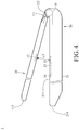
- Fig. 4 is a schematic side view of the electronic device as the second body is at another position in an embodiment.
- the first body 10 is at a second position relative to the second body 20.
- the magnetic sensor 22 and the magnetic member 12 have a second distance therebetween.
- the second distance L2 between the magnetic sensor 22 and the magnetic member 12 at the first position is longer than the third distance L3 between the magnetic sensor 22 and the magnetic member 12 at the second position.
- the magnetic flux of the magnetic member 12 detected by the magnetic sensor 22 is larger than the first value, so the switch control component 24 turns off the electronic component 40 by switching off the switch of the electronic component 40.
- the first body 10 is pivoted away from the fourth side 214 of the second case 21 of the second body 20 until the magnetic flux of the magnetic member 12 detected by the magnetic sensor 22 is smaller than or substantially equal to a certain value, so as to automatically turn on the electronic component 40.
- a control group is established, in which no magnetism guiding member 23 (e.g. ferrite sheet) is disposed as magnetic members 12 (e.g. permanent magnets) respectively have 1, 2, 3 and 4 cm distances with a magnetic sensor.
- the magnetic sensor senses that magnetic fluxes of the magnetic members 12 are respectively 70, 25, 3 and 2 gausses.
- an experimental group is established, in which magnetism guiding members 23 are disposed to a magnetic sensor as magnetic members 12 respectively have 1, 2, 3 and 4 cm distances with the magnetic sensor.
- the magnetic sensor senses that the magnetic fluxes of the magnetic members 12 are respectively 143, 78, 52 and 21 gausses.
- the magnetism guiding members 23 can enlarge and guide the magnetic field. Therefore, the electronic device 1 in the disclosure can be disposed with a magnetic sensor having relatively-few power consumption and a relatively-small size and still achieve the same sensing effect. Also, under the same power consumption, the magnetic sensor and the magnetic members 12 can be disposed far away from the pivot member, so as to avoid the interference from the permeability of the pivot member. Additionally, the dispositions of the magnetism guiding members 23 and the magnetic sensor can be designed according to a variety of conditions to achieve a small, light, thin electronic device 1.
- the disposition of the pivot member 30 does not limit the disclosure; in another embodiment, even if the pivot member 30 is removed, the disclosure still can control the switching of the switch of the electronic component 40 by employing the magnetic sensor 22 to monitor the magnetic field of the magnetic member 12 extended by the magnetism guiding member 23.
- one or more magnetism guiding members are disposed to one or more magnetic sensors to extend and guide the magnetic field caused by one or more magnetic members. Therefore, such a magnetic sensor still could sense the magnetic field of the magnetic member even if the magnetic sensor is far from the magnetic member. In this way, the magnetic sensor and the magnetic member can be disposed at a respective better position to avoid the interference from other components (such as a pivot member) and enhance the sensing accuracy. Moreover, a magnetic sensor having relatively-few power consumption is chosen as maintaining its sensing effect, so the disclosure may save power.
- the disclosure further provides a variety of designs for the appearance of the above magnetism guiding member 23 to increase the detectable distance of the above magnetic sensor 22 and enhance the sensitivity of the above magnetic sensor 22.
- the following exemplarily illustrates different designs of the magnetism guiding member 23 in different embodiments to, and however, the disclosure is not limited to these embodiments.
- FIG. 5A is a top view of a magnetism guiding member in an embodiment of the disclosure.
- the magnetism guiding member 23a includes a permeance body 231 and an extended member 232a.
- the extended member 232a extends from a side of the permeance body 231.
- An edge 233a of the extended member 232a on a side far from the permeance body 231 includes a first edge segment S1a, a second edge segment S2a and a third edge segment S3a.
- Two opposite ends of the second edge segment S2a respectively abut the first edge segment S1a and the third edge segment S3a, and the first edge segment S1a and the third edge segment S3a abut the permeance body 231.
- the first edge segment S1a and a first edge 2311 of the permeance body 231 adjacent to the first edge segment S1a have an angle ⁇ 1a therebetween
- the extension direction of the first edge segment S1a and the extension direction of the third edge segment S3a have an angle ⁇ 2a therebetween
- the third edge segment S3a and a second edge 2312 of the permeance body 231 adjacent to the third edge segment S3a have an angle ⁇ 3a therebetween.
- the permeance body 231 is, for example, but not limited to, a quadrilateral plate. In other embodiments, the shape of the permeance body 231 can be designed according to requirements of actual applications.
- first edge segment S1a and the third edge segment S3a are symmetric. In another embodiment, the first edge segment S1a and the third edge segment S3a are asymmetric.
- first edge segment S1a and the third edge segment S3a are not limited to be substantially straight. In other embodiments, at least one of the first edge segment S1a and the third edge segment S3a is a straight line, a curve or a combination thereof.
- first edge segment S1a and the third edge segment S3a are not limited to have the same distance. In other embodiments, the first edge segment S1a and the third edge segment S3a have different distances.
- the second edge segment S2a is substantially straight, but the disclosure is not limited thereto.
- the second edge segment S2a is a curve, such an arc, a curve constituted by arcs, or a curve constituted by at least one arc and at least one straight line.
- the length of the second edge segment S2a can be designed according to requirements of actual applications, and the disclosure has no limitation thereon.
- the second edge segment S2a can be configured to contact the magnetic sensor 22 in the aforementioned embodiments. In other embodiments, the second edge segment S2a can be adjacent to but not contact the magnetic sensor 22.
- angles ⁇ 1a and ⁇ 3a are substantially the same, but the disclosure is not limited thereto. In other embodiments, the angles ⁇ 1a and ⁇ 3a are different.
- the angle ⁇ 2a of the magnetism guiding member 23a is 40 degrees, but the disclosure is not limited thereto.
- the extension direction of the first edge segment S1b and the extension direction of the third edge segment S3b have an angle ⁇ 2b of 60 degrees therebetween;
- the extension direction of the first edge segment S1c and the extension direction of the third edge segment S3c have an angle ⁇ 2c of 90 degrees therebetween; and for the extended member 232d of the magnetism guiding member 23d as shown in FIG.
- the extension direction of the first edge segment S1d and the extension direction of the third edge segment S3d have an angle ⁇ 2d of 130 degrees therebetween.
- the disclosure does not limit the angle between the extension direction of the first edge segment and the extension direction of the third edge segment.
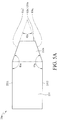
- FIG. 6 is a top view of a magnetism guiding member in another embodiment of the disclosure.
- the magnetism guiding member 23e includes a permeance body 231 and an extended member 232e.
- the extended member 232e extends from a side of the permeance body 231.
- An edge 233e of the extended member 232e on a side far from the permeance body 231 includes a first edge segment S1e, a second edge segment S2e and a third edge segment S3e.
- Two opposite ends of the second edge segment S2e respectively abut the first edge segment S1e and the third edge segment S3e, and the first edge segment S1e and the third edge segment S3e respectively abut a first edge 2311 and a second edge 2312 of the permeance body 231.
- first edge segment S1e and the third edge segment S3e are symmetric to each other. In another embodiment, the first edge segment S1e and the third edge segment S3e are asymmetric to each other.
- first edge segment S1e and the third edge segment S3e substantially have the same distance, but the disclosure is not limited thereto. In other embodiments, the first edge segment S1e and the third edge segment S3e have different distances.
- the second edge segment S2e is substantially straight, but the disclosure is not limited thereto.
- the second edge segment S2e can be a curve, such as an arc, a curve constituted by more than one arc, or a curve constituted by at least one arc and at least one straight line.
- the length of the second edge segment S2e can be designed according to requirements of actual applications, and the disclosure does not limit it.
- the second edge segment S2e can contact the magnetic sensor 22 in the aforementioned embodiments. In other embodiments, the second edge segment S2e can merely be adjacent to the magnetic sensor 22 but not contact it.
- the permeance body 231 is exemplarily a quadrilateral plate, but the disclosure is not limited thereto. In other embodiments, the shape of the permeance body 231 can be designed according to requirements of actual applications.
- the following exemplarily introduces the magnetism guiding ability of magnetism guiding members with different appearances by experiments.
- the following experiments are made by the following conditions: selecting a ferrite plate as the material of the magnetism guiding members 23a to 23e, selecting a permanent magnet as the magnetic member 12, selecting a Hall sensor as the magnetic sensor 22, and setting the distance between the magnetic member 12 and the magnetic sensor 22 to be constant.
- a control group is designed that the magnetic flux caused by the above magnetic member 12 is directly measured by the above magnetic sensor 22 without the disposition of any magnetism guiding member, and then the magnetic sensor 22 can obtain the magnetic flux of 15 gausses.
- different units of an experimental group are designed.
- the second edge segment S2a of the above magnetism guiding member 23a is connected to the magnetic sensor 22, and the magnetism guiding member 23a is disposed under the magnetic sensor 22.
- the second edge segment S2b of the above magnetism guiding member 23b is connected to the magnetic sensor 22, and the magnetism guiding member 23b is disposed under the magnetic sensor 22.
- the magnetic sensor 22, corresponding to the magnetism guiding member 23b that the extension direction of the first edge segment S1b and the extension direction of the third edge segment S3b have an angle ⁇ 2b of 60 degrees therebetween, can sense and obtain the magnetic flux of 35 gausses.
- the second edge segment S2c of the above magnetism guiding member 23c is connected to the magnetic sensor 22, and the magnetism guiding member 23c is disposed under the magnetic sensor 22.
- the magnetic sensor 22, corresponding to the magnetism guiding member 23c that the extension direction of the first edge segment S1c and the extension direction of the third edge segment S3c have an angle ⁇ 2c of 90 degrees therebetween, can sense and obtain the magnetic flux of 31 gausses.
- the second edge segment S2d of the above magnetism guiding member 23d is connected to the magnetic sensor 22, and the magnetism guiding member 23d is disposed under the magnetic sensor 22.
- the magnetic sensor 22, corresponding to the magnetism guiding member 23d that the extension direction of the first edge segment S1d and the extension direction of the third edge segment S3d have an angle ⁇ 2d of 130 degrees therebetween, can sense and obtain the magnetic flux of 24 gausses.
- the second edge segment S2be of the above magnetism guiding member 23e is connected to the magnetic sensor 22, and the magnetism guiding member 23e is disposed under the magnetic sensor 22. In this case, the magnetic sensor 22 corresponding to the magnetism guiding member 23e can sense and obtain the magnetic flux of 32 gausses.
- the various design of the appearance of magnetism guiding members can achieve an effect of strengthening magnetic force, especially magnetism guiding members that the extension direction of the first edge segment and the extension direction of the third edge segment have an angle ranging between 40 degrees and 130 degrees therebetween (e.g. the magnetism guiding members 23b, 23c and 23d) and magnetism guiding members having a semicircular construction with a cut portion (e.g. the magnetism guiding member 23e) have a better effect of strengthening magnetic force.
Landscapes
- Engineering & Computer Science (AREA)
- Theoretical Computer Science (AREA)
- Computer Hardware Design (AREA)
- Physics & Mathematics (AREA)
- General Engineering & Computer Science (AREA)
- General Physics & Mathematics (AREA)
- Human Computer Interaction (AREA)
- Mathematical Physics (AREA)
- Switches That Are Operated By Magnetic Or Electric Fields (AREA)
- Computing Systems (AREA)
- Transmission And Conversion Of Sensor Element Output (AREA)
Claims (13)
- Elektronische Vorrichtung (1) mit einem ersten Körper (10) und einem zweiten Körper (20), wobei der erste Körper (10) ein erstes Gehäuse (11) und ein in dem ersten Gehäuse (11) angeordnetes magnetisches Element (12) aufweist, wobei der zweite Körper (21) ein zweites Gehäuse (21) und einen Magnetsensor (22) und ein Schaltsteuerelement (24) aufweist, welche in dem zweiten Gehäuse (21) angeordnet sind, wobei das zweite Gehäuse (21) bewegbar mit dem ersten Körper (10) verbunden ist, wobei das Schaltsteuerelement (24) elektrisch mit dem Magnetsensor (22) verbunden ist, wobei:der zweite Körper (20) ein in dem zweiten Gehäuse (21) angeordnetes Magnetismusleitelement (23) aufweist, wobei der Magnetsensor (22) auf dem Magnetismusleitelement (23) angeordnet ist, wobei das zweite Gehäuse (21) des zweiten Körpers (20) eine Oberseite (211) aufweist, wobei der Magnetsensor (22) zwischen der Oberseite (211) und dem Magnetismusleitelement (23) derart angeordnet ist, dass der Magnetsensor (22) sich zwischen dem magnetischen Element (12) und dem Magnetismusleitelement (23) befindet, wenn das erste Gehäuse (11) des ersten Körpers (10) auf das zweite Gehäuse (21) des zweiten Körpers (20) geschlossen ist, wobei das Magnetismusleitelement (23) dazu ausgebildet ist, ein von dem magnetischen Element (12) bewirktes magnetisches Feld zu leiten, und wobei der Magnetsensor (22) dazu ausgebildet ist, einen von dem magnetischen Element (12) bewirkten Magnetfluss zu detektieren,wobei das Magnetismusleitelement einen Permeanzkörper (231) und ein Erweiterungselement (232a, 232b, 232c, 232d, 232e) aufweist, und wobei sich das Erweiterungselement von einer Seite des Permeanzkörper erstreckt, wobei ein dem Permeanzkörper abgewandter Rand des Erweiterungselements ein erstes Randsegment (S1a, S1b, S1c, S1d, S1e), ein zweites Randsegment (S2a, S2b, S2c, S2d, S2e) und ein drittes Randsegment (S3a, S3b, S3c, S3d, S3e) aufweist, wobei zwei Enden des zweiten Randsegments mit dem ersten Randsegment bzw. dem dritten Randsegment verbunden sind, wobei das erste Randsegment und das dritte Randsegment mit dem Permeanzkörper verbunden sind, wobei das erste Randsegment, das zweite Randsegment und das dritte Randsegment sich entlang derselben Ebene erstrecken, und wobei eine Erstreckungsrichtung des ersten Randsegments und eine Erstreckungsrichtung des dritten Randsegments zwischen sich einen Winkel (θ2a, θ2b, θ2c, θ2d) aufweisen, und wobei der Winkelbereich zwischen 40 Grad und 130 Grad liegt.
- Elektronische Vorrichtung (1) nach Anspruch 1, bei welcher der erste Körper (10) eine erste Seite aufweist, der zweite Körper (20) eine zweite Seite aufweist, und die elektronische Vorrichtung (1) ferner ein Schwenkelement (30) aufweist, das schwenkbar mit der ersten Seite des ersten Körpers (10) und der zweiten Seite des zweiten Körpers (20) verbunden ist.
- Elektronische Vorrichtung (1) nach Anspruch 2, bei welcher ein Abstand zwischen dem Magnetsensor (22) und dem Schwenkelement (30) im Wesentlichen gleich einem Abstand zwischen dem Magnetsensor (22) und dem Schwenkelement (30) ist.
- Elektronische Vorrichtung (1) nach Anspruch 2, bei welcher der erste Körper (10) mit dem zweiten Körper (20) durch ein Schwenkelement (30) verbunden ist, so dass der erste Körper (10) in Bezug auf den zweiten Körper (20) in eine erste Position oder eine zweite Position bewegbar ist, und wobei ein Abstand zwischen dem Magnetsensor (22) und dem magnetischen Element (12) in der ersten Position größer als ein anderer Abstand zwischen dem Magnetsensor (22) und dem magnetischen Element (12) in der zweiten Position ist.
- Elektronische Vorrichtung (1) nach Anspruch 1, bei welcher der Magnetsensor (22) ein Hall-Sensor ist.
- Elektronische Vorrichtung (1) nach Anspruch 1, bei welcher das magnetische Element (12) ein Permanentmagnet ist.
- Elektronische Vorrichtung (1) nach Anspruch 1, bei welcher das Magnetismusleitelement (23) aus Ferrit oder Siliziumstahl besteht.
- Elektronische Vorrichtung (1) nach Anspruch 1, bei welcher die elektronische Komponente (40) ein Display ist, und das Display an dem ersten Gehäuse (11) oder dem zweiten Gehäuse (21) angeordnet ist.
- Elektronische Vorrichtung (1) nach Anspruch 1, bei welcher ein auf der von dem Permeanzkörper (231) abgewandten Seite befindlicher Rand des Erweiterungselements ein Bogen ist oder mindestens einen Bruchwinkel/Öffnungswinkel aufweist.
- Elektronische Vorrichtung (1) nach Anspruch 9, bei welcher das erste Randsegment und das dritte Randsegment im Wesentlichen gerade sind.
- Elektronische Vorrichtung (1) nach Anspruch 1, bei welcher das erste Randsegment und das dritte Randsegment gebogen sind.
- Elektronische Vorrichtung (1) nach Anspruch 1, bei welcher das Erweiterungselement eine symmetrische Form oder eine asymmetrische Form aufweist.
- Elektronische Vorrichtung (1) nach Anspruch 1, bei welcher das Permeanzkörper (231) eine vierseitige Platte ist.
Applications Claiming Priority (2)
| Application Number | Priority Date | Filing Date | Title |
|---|---|---|---|
| TW104215241U TWM514096U (zh) | 2015-09-21 | 2015-09-21 | 電子裝置 |
| TW105211361U TWM535337U (zh) | 2016-07-27 | 2016-07-27 | 電子裝置 |
Publications (2)
| Publication Number | Publication Date |
|---|---|
| EP3144769A1 EP3144769A1 (de) | 2017-03-22 |
| EP3144769B1 true EP3144769B1 (de) | 2019-12-25 |
Family
ID=56939911
Family Applications (1)
| Application Number | Title | Priority Date | Filing Date |
|---|---|---|---|
| EP16189108.0A Active EP3144769B1 (de) | 2015-09-21 | 2016-09-16 | Elektronische vorrichtung |
Country Status (2)
| Country | Link |
|---|---|
| US (1) | US10338643B2 (de) |
| EP (1) | EP3144769B1 (de) |
Families Citing this family (7)
| Publication number | Priority date | Publication date | Assignee | Title |
|---|---|---|---|---|
| US11832100B2 (en) | 2017-05-16 | 2023-11-28 | Apple Inc. | Secure password sharing for wireless networks |
| CN108958375B (zh) * | 2018-06-25 | 2022-04-22 | 联想(北京)有限公司 | 一种形态检测方法、形态检测装置及电子设备 |
| CN109240521B (zh) * | 2018-09-21 | 2020-09-01 | 合肥京东方光电科技有限公司 | 主动式触控笔、触控输入系统及其驱动方法 |
| US10955494B2 (en) * | 2018-09-26 | 2021-03-23 | Apple Inc. | Magnetic field sensor in a portable electronic device |
| USD983194S1 (en) * | 2018-10-05 | 2023-04-11 | Samsung Display Co., Ltd. | Notebook computer |
| CN109213275B (zh) * | 2018-11-26 | 2020-10-02 | 英业达科技有限公司 | 笔记本电脑 |
| EP4365707A1 (de) * | 2021-08-10 | 2024-05-08 | Samsung Electronics Co., Ltd. | Elektronische vorrichtung mit hallsensor zur identifizierung des faltzustands |
Citations (2)
| Publication number | Priority date | Publication date | Assignee | Title |
|---|---|---|---|---|
| EP2395731A1 (de) * | 2010-06-10 | 2011-12-14 | Research In Motion Limited | Mobile drahtlose Kommunikationsvorrichtung mit magnetisch leitfähigem Körper und zugehöriges Verfahren |
| CN104157069A (zh) * | 2013-05-14 | 2014-11-19 | 北京嘉岳同乐极电子有限公司 | 高灵敏度磁传感器 |
Family Cites Families (4)
| Publication number | Priority date | Publication date | Assignee | Title |
|---|---|---|---|---|
| US6356741B1 (en) * | 1998-09-18 | 2002-03-12 | Allegro Microsystems, Inc. | Magnetic pole insensitive switch circuit |
| JP3811454B2 (ja) * | 2003-01-29 | 2006-08-23 | インターナショナル・ビジネス・マシーンズ・コーポレーション | 近接検出装置、ポータブルコンピュータ、近接検出方法、及びプログラム |
| CN100554885C (zh) * | 2005-04-19 | 2009-10-28 | 松下电器产业株式会社 | 位置传感器、光头装置、头部移动机构及位置控制系统 |
| CN101400247B (zh) * | 2007-09-26 | 2010-09-29 | 鸿富锦精密工业(深圳)有限公司 | 电子装置 |
-
2016
- 2016-09-16 EP EP16189108.0A patent/EP3144769B1/de active Active
- 2016-09-20 US US15/271,098 patent/US10338643B2/en not_active Expired - Fee Related
Patent Citations (2)
| Publication number | Priority date | Publication date | Assignee | Title |
|---|---|---|---|---|
| EP2395731A1 (de) * | 2010-06-10 | 2011-12-14 | Research In Motion Limited | Mobile drahtlose Kommunikationsvorrichtung mit magnetisch leitfähigem Körper und zugehöriges Verfahren |
| CN104157069A (zh) * | 2013-05-14 | 2014-11-19 | 北京嘉岳同乐极电子有限公司 | 高灵敏度磁传感器 |
Also Published As
| Publication number | Publication date |
|---|---|
| EP3144769A1 (de) | 2017-03-22 |
| US20170083055A1 (en) | 2017-03-23 |
| US10338643B2 (en) | 2019-07-02 |
Similar Documents
| Publication | Publication Date | Title |
|---|---|---|
| EP3144769B1 (de) | Elektronische vorrichtung | |
| US9798399B2 (en) | Side sensing for electronic devices | |
| US8988351B2 (en) | Input device, and electronic apparatus provided with same | |
| WO2015072498A1 (ja) | 電子機器 | |
| KR102047882B1 (ko) | 커버를 구비하는 전자 장치 | |
| EP1975762A1 (de) | Informationsverarbeitungsvorrichtung | |
| US9164614B2 (en) | Electronic device that invalidates touch input when relative movement between display screens is detected | |
| US20170084407A1 (en) | Button mechanism | |
| JP2011221675A (ja) | 携帯電子機器 | |
| JP2012212230A (ja) | 電子機器 | |
| CN102012724B (zh) | 一种终端设备及触摸屏 | |
| US9432490B2 (en) | Portable sliding electronic device operable to disable a touchscreen display when opening and closing the device | |
| JPWO2010047075A1 (ja) | 携帯装置における状態検出装置および方法 | |
| CN106790859B (zh) | 应用于智能终端设备的保护套 | |
| JPWO2014132965A1 (ja) | 携帯電子機器、その制御方法及びプログラム | |
| CN103677616A (zh) | 一种电子装置的操作方法 | |
| CN205899453U (zh) | 电子装置 | |
| KR101630767B1 (ko) | 홀 센서를 이용한 사용자 단말 및 이를 포함하는 센싱 시스템 | |
| TWI650527B (zh) | 可攜式電子裝置及控制方法 | |
| US20150074593A1 (en) | Portable electronic device and method for controlling displayed information thereof | |
| TWM535337U (zh) | 電子裝置 | |
| US20120176331A1 (en) | Rotation detection device and mobile terminal provided with same | |
| CN204925917U (zh) | 电子装置 | |
| CN205050106U (zh) | 用于触摸屏终端的智能传感器 | |
| JP2013175888A (ja) | 携帯型電子機器 |
Legal Events
| Date | Code | Title | Description |
|---|---|---|---|
| PUAI | Public reference made under article 153(3) epc to a published international application that has entered the european phase |
Free format text: ORIGINAL CODE: 0009012 |
|
| STAA | Information on the status of an ep patent application or granted ep patent |
Free format text: STATUS: THE APPLICATION HAS BEEN PUBLISHED |
|
| AK | Designated contracting states |
Kind code of ref document: A1 Designated state(s): AL AT BE BG CH CY CZ DE DK EE ES FI FR GB GR HR HU IE IS IT LI LT LU LV MC MK MT NL NO PL PT RO RS SE SI SK SM TR |
|
| AX | Request for extension of the european patent |
Extension state: BA ME |
|
| STAA | Information on the status of an ep patent application or granted ep patent |
Free format text: STATUS: REQUEST FOR EXAMINATION WAS MADE |
|
| 17P | Request for examination filed |
Effective date: 20170802 |
|
| RBV | Designated contracting states (corrected) |
Designated state(s): AL AT BE BG CH CY CZ DE DK EE ES FI FR GB GR HR HU IE IS IT LI LT LU LV MC MK MT NL NO PL PT RO RS SE SI SK SM TR |
|
| STAA | Information on the status of an ep patent application or granted ep patent |
Free format text: STATUS: EXAMINATION IS IN PROGRESS |
|
| 17Q | First examination report despatched |
Effective date: 20180410 |
|
| REG | Reference to a national code |
Ref country code: DE Ref legal event code: R079 Ref document number: 602016026731 Country of ref document: DE Free format text: PREVIOUS MAIN CLASS: G06F0001160000 Ipc: G06F0001328700 |
|
| GRAP | Despatch of communication of intention to grant a patent |
Free format text: ORIGINAL CODE: EPIDOSNIGR1 |
|
| STAA | Information on the status of an ep patent application or granted ep patent |
Free format text: STATUS: GRANT OF PATENT IS INTENDED |
|
| RIC1 | Information provided on ipc code assigned before grant |
Ipc: G06F 1/3206 20190101ALI20190620BHEP Ipc: G06F 1/16 20060101ALI20190620BHEP Ipc: G06F 1/32 20190101ALI20190620BHEP Ipc: G06F 1/3287 20190101AFI20190620BHEP |
|
| INTG | Intention to grant announced |
Effective date: 20190717 |
|
| RIN1 | Information on inventor provided before grant (corrected) |
Inventor name: WU, CHIEN-TE |
|
| GRAS | Grant fee paid |
Free format text: ORIGINAL CODE: EPIDOSNIGR3 |
|
| GRAA | (expected) grant |
Free format text: ORIGINAL CODE: 0009210 |
|
| STAA | Information on the status of an ep patent application or granted ep patent |
Free format text: STATUS: THE PATENT HAS BEEN GRANTED |
|
| AK | Designated contracting states |
Kind code of ref document: B1 Designated state(s): AL AT BE BG CH CY CZ DE DK EE ES FI FR GB GR HR HU IE IS IT LI LT LU LV MC MK MT NL NO PL PT RO RS SE SI SK SM TR |
|
| REG | Reference to a national code |
Ref country code: GB Ref legal event code: FG4D |
|
| REG | Reference to a national code |
Ref country code: CH Ref legal event code: EP |
|
| REG | Reference to a national code |
Ref country code: AT Ref legal event code: REF Ref document number: 1217834 Country of ref document: AT Kind code of ref document: T Effective date: 20200115 |
|
| REG | Reference to a national code |
Ref country code: DE Ref legal event code: R096 Ref document number: 602016026731 Country of ref document: DE |
|
| REG | Reference to a national code |
Ref country code: IE Ref legal event code: FG4D |
|
| REG | Reference to a national code |
Ref country code: NL Ref legal event code: FP |
|
| PG25 | Lapsed in a contracting state [announced via postgrant information from national office to epo] |
Ref country code: LT Free format text: LAPSE BECAUSE OF FAILURE TO SUBMIT A TRANSLATION OF THE DESCRIPTION OR TO PAY THE FEE WITHIN THE PRESCRIBED TIME-LIMIT Effective date: 20191225 Ref country code: NO Free format text: LAPSE BECAUSE OF FAILURE TO SUBMIT A TRANSLATION OF THE DESCRIPTION OR TO PAY THE FEE WITHIN THE PRESCRIBED TIME-LIMIT Effective date: 20200325 Ref country code: GR Free format text: LAPSE BECAUSE OF FAILURE TO SUBMIT A TRANSLATION OF THE DESCRIPTION OR TO PAY THE FEE WITHIN THE PRESCRIBED TIME-LIMIT Effective date: 20200326 Ref country code: LV Free format text: LAPSE BECAUSE OF FAILURE TO SUBMIT A TRANSLATION OF THE DESCRIPTION OR TO PAY THE FEE WITHIN THE PRESCRIBED TIME-LIMIT Effective date: 20191225 Ref country code: FI Free format text: LAPSE BECAUSE OF FAILURE TO SUBMIT A TRANSLATION OF THE DESCRIPTION OR TO PAY THE FEE WITHIN THE PRESCRIBED TIME-LIMIT Effective date: 20191225 Ref country code: BG Free format text: LAPSE BECAUSE OF FAILURE TO SUBMIT A TRANSLATION OF THE DESCRIPTION OR TO PAY THE FEE WITHIN THE PRESCRIBED TIME-LIMIT Effective date: 20200325 Ref country code: SE Free format text: LAPSE BECAUSE OF FAILURE TO SUBMIT A TRANSLATION OF THE DESCRIPTION OR TO PAY THE FEE WITHIN THE PRESCRIBED TIME-LIMIT Effective date: 20191225 |
|
| REG | Reference to a national code |
Ref country code: LT Ref legal event code: MG4D |
|
| PG25 | Lapsed in a contracting state [announced via postgrant information from national office to epo] |
Ref country code: RS Free format text: LAPSE BECAUSE OF FAILURE TO SUBMIT A TRANSLATION OF THE DESCRIPTION OR TO PAY THE FEE WITHIN THE PRESCRIBED TIME-LIMIT Effective date: 20191225 Ref country code: HR Free format text: LAPSE BECAUSE OF FAILURE TO SUBMIT A TRANSLATION OF THE DESCRIPTION OR TO PAY THE FEE WITHIN THE PRESCRIBED TIME-LIMIT Effective date: 20191225 |
|
| PG25 | Lapsed in a contracting state [announced via postgrant information from national office to epo] |
Ref country code: AL Free format text: LAPSE BECAUSE OF FAILURE TO SUBMIT A TRANSLATION OF THE DESCRIPTION OR TO PAY THE FEE WITHIN THE PRESCRIBED TIME-LIMIT Effective date: 20191225 |
|
| PG25 | Lapsed in a contracting state [announced via postgrant information from national office to epo] |
Ref country code: PT Free format text: LAPSE BECAUSE OF FAILURE TO SUBMIT A TRANSLATION OF THE DESCRIPTION OR TO PAY THE FEE WITHIN THE PRESCRIBED TIME-LIMIT Effective date: 20200520 Ref country code: EE Free format text: LAPSE BECAUSE OF FAILURE TO SUBMIT A TRANSLATION OF THE DESCRIPTION OR TO PAY THE FEE WITHIN THE PRESCRIBED TIME-LIMIT Effective date: 20191225 Ref country code: RO Free format text: LAPSE BECAUSE OF FAILURE TO SUBMIT A TRANSLATION OF THE DESCRIPTION OR TO PAY THE FEE WITHIN THE PRESCRIBED TIME-LIMIT Effective date: 20191225 Ref country code: CZ Free format text: LAPSE BECAUSE OF FAILURE TO SUBMIT A TRANSLATION OF THE DESCRIPTION OR TO PAY THE FEE WITHIN THE PRESCRIBED TIME-LIMIT Effective date: 20191225 |
|
| PG25 | Lapsed in a contracting state [announced via postgrant information from national office to epo] |
Ref country code: SK Free format text: LAPSE BECAUSE OF FAILURE TO SUBMIT A TRANSLATION OF THE DESCRIPTION OR TO PAY THE FEE WITHIN THE PRESCRIBED TIME-LIMIT Effective date: 20191225 Ref country code: IS Free format text: LAPSE BECAUSE OF FAILURE TO SUBMIT A TRANSLATION OF THE DESCRIPTION OR TO PAY THE FEE WITHIN THE PRESCRIBED TIME-LIMIT Effective date: 20200425 Ref country code: SM Free format text: LAPSE BECAUSE OF FAILURE TO SUBMIT A TRANSLATION OF THE DESCRIPTION OR TO PAY THE FEE WITHIN THE PRESCRIBED TIME-LIMIT Effective date: 20191225 |
|
| REG | Reference to a national code |
Ref country code: DE Ref legal event code: R097 Ref document number: 602016026731 Country of ref document: DE |
|
| PG25 | Lapsed in a contracting state [announced via postgrant information from national office to epo] |
Ref country code: ES Free format text: LAPSE BECAUSE OF FAILURE TO SUBMIT A TRANSLATION OF THE DESCRIPTION OR TO PAY THE FEE WITHIN THE PRESCRIBED TIME-LIMIT Effective date: 20191225 Ref country code: DK Free format text: LAPSE BECAUSE OF FAILURE TO SUBMIT A TRANSLATION OF THE DESCRIPTION OR TO PAY THE FEE WITHIN THE PRESCRIBED TIME-LIMIT Effective date: 20191225 |
|
| PLBE | No opposition filed within time limit |
Free format text: ORIGINAL CODE: 0009261 |
|
| STAA | Information on the status of an ep patent application or granted ep patent |
Free format text: STATUS: NO OPPOSITION FILED WITHIN TIME LIMIT |
|
| REG | Reference to a national code |
Ref country code: AT Ref legal event code: MK05 Ref document number: 1217834 Country of ref document: AT Kind code of ref document: T Effective date: 20191225 |
|
| PG25 | Lapsed in a contracting state [announced via postgrant information from national office to epo] |
Ref country code: SI Free format text: LAPSE BECAUSE OF FAILURE TO SUBMIT A TRANSLATION OF THE DESCRIPTION OR TO PAY THE FEE WITHIN THE PRESCRIBED TIME-LIMIT Effective date: 20191225 |
|
| 26N | No opposition filed |
Effective date: 20200928 |
|
| PG25 | Lapsed in a contracting state [announced via postgrant information from national office to epo] |
Ref country code: AT Free format text: LAPSE BECAUSE OF FAILURE TO SUBMIT A TRANSLATION OF THE DESCRIPTION OR TO PAY THE FEE WITHIN THE PRESCRIBED TIME-LIMIT Effective date: 20191225 Ref country code: IT Free format text: LAPSE BECAUSE OF FAILURE TO SUBMIT A TRANSLATION OF THE DESCRIPTION OR TO PAY THE FEE WITHIN THE PRESCRIBED TIME-LIMIT Effective date: 20191225 |
|
| PG25 | Lapsed in a contracting state [announced via postgrant information from national office to epo] |
Ref country code: PL Free format text: LAPSE BECAUSE OF FAILURE TO SUBMIT A TRANSLATION OF THE DESCRIPTION OR TO PAY THE FEE WITHIN THE PRESCRIBED TIME-LIMIT Effective date: 20191225 |
|
| PG25 | Lapsed in a contracting state [announced via postgrant information from national office to epo] |
Ref country code: MC Free format text: LAPSE BECAUSE OF FAILURE TO SUBMIT A TRANSLATION OF THE DESCRIPTION OR TO PAY THE FEE WITHIN THE PRESCRIBED TIME-LIMIT Effective date: 20191225 |
|
| REG | Reference to a national code |
Ref country code: CH Ref legal event code: PL |
|
| GBPC | Gb: european patent ceased through non-payment of renewal fee |
Effective date: 20200916 |
|
| REG | Reference to a national code |
Ref country code: BE Ref legal event code: MM Effective date: 20200930 |
|
| PG25 | Lapsed in a contracting state [announced via postgrant information from national office to epo] |
Ref country code: LU Free format text: LAPSE BECAUSE OF NON-PAYMENT OF DUE FEES Effective date: 20200916 |
|
| PG25 | Lapsed in a contracting state [announced via postgrant information from national office to epo] |
Ref country code: FR Free format text: LAPSE BECAUSE OF NON-PAYMENT OF DUE FEES Effective date: 20200930 |
|
| PG25 | Lapsed in a contracting state [announced via postgrant information from national office to epo] |
Ref country code: BE Free format text: LAPSE BECAUSE OF NON-PAYMENT OF DUE FEES Effective date: 20200930 Ref country code: CH Free format text: LAPSE BECAUSE OF NON-PAYMENT OF DUE FEES Effective date: 20200930 Ref country code: IE Free format text: LAPSE BECAUSE OF NON-PAYMENT OF DUE FEES Effective date: 20200916 Ref country code: LI Free format text: LAPSE BECAUSE OF NON-PAYMENT OF DUE FEES Effective date: 20200930 Ref country code: GB Free format text: LAPSE BECAUSE OF NON-PAYMENT OF DUE FEES Effective date: 20200916 |
|
| PGFP | Annual fee paid to national office [announced via postgrant information from national office to epo] |
Ref country code: NL Payment date: 20210915 Year of fee payment: 6 |
|
| PG25 | Lapsed in a contracting state [announced via postgrant information from national office to epo] |
Ref country code: TR Free format text: LAPSE BECAUSE OF FAILURE TO SUBMIT A TRANSLATION OF THE DESCRIPTION OR TO PAY THE FEE WITHIN THE PRESCRIBED TIME-LIMIT Effective date: 20191225 Ref country code: MT Free format text: LAPSE BECAUSE OF FAILURE TO SUBMIT A TRANSLATION OF THE DESCRIPTION OR TO PAY THE FEE WITHIN THE PRESCRIBED TIME-LIMIT Effective date: 20191225 Ref country code: CY Free format text: LAPSE BECAUSE OF FAILURE TO SUBMIT A TRANSLATION OF THE DESCRIPTION OR TO PAY THE FEE WITHIN THE PRESCRIBED TIME-LIMIT Effective date: 20191225 |
|
| PG25 | Lapsed in a contracting state [announced via postgrant information from national office to epo] |
Ref country code: MK Free format text: LAPSE BECAUSE OF FAILURE TO SUBMIT A TRANSLATION OF THE DESCRIPTION OR TO PAY THE FEE WITHIN THE PRESCRIBED TIME-LIMIT Effective date: 20191225 |
|
| PGFP | Annual fee paid to national office [announced via postgrant information from national office to epo] |
Ref country code: DE Payment date: 20220609 Year of fee payment: 7 |
|
| REG | Reference to a national code |
Ref country code: NL Ref legal event code: MM Effective date: 20221001 |
|
| PG25 | Lapsed in a contracting state [announced via postgrant information from national office to epo] |
Ref country code: NL Free format text: LAPSE BECAUSE OF NON-PAYMENT OF DUE FEES Effective date: 20221001 |
|
| REG | Reference to a national code |
Ref country code: DE Ref legal event code: R119 Ref document number: 602016026731 Country of ref document: DE |