EP3143790B1 - Zugriff auf einen kommunikationskanal in einem drahtloskommunikationsnetzwerk - Google Patents
Zugriff auf einen kommunikationskanal in einem drahtloskommunikationsnetzwerk Download PDFInfo
- Publication number
- EP3143790B1 EP3143790B1 EP14723084.1A EP14723084A EP3143790B1 EP 3143790 B1 EP3143790 B1 EP 3143790B1 EP 14723084 A EP14723084 A EP 14723084A EP 3143790 B1 EP3143790 B1 EP 3143790B1
- Authority
- EP
- European Patent Office
- Prior art keywords
- stas
- group
- time interval
- access
- communications channel
- Prior art date
- Legal status (The legal status is an assumption and is not a legal conclusion. Google has not performed a legal analysis and makes no representation as to the accuracy of the status listed.)
- Active
Links
- 238000004891 communication Methods 0.000 title claims description 108
- 230000005540 biological transmission Effects 0.000 claims description 78
- 238000000034 method Methods 0.000 claims description 57
- 238000012545 processing Methods 0.000 claims description 30
- 238000004590 computer program Methods 0.000 claims description 28
- 101100172132 Mus musculus Eif3a gene Proteins 0.000 claims description 9
- 101000741965 Homo sapiens Inactive tyrosine-protein kinase PRAG1 Proteins 0.000 claims 1
- 102100038659 Inactive tyrosine-protein kinase PRAG1 Human genes 0.000 claims 1
- VYLDEYYOISNGST-UHFFFAOYSA-N bissulfosuccinimidyl suberate Chemical compound O=C1C(S(=O)(=O)O)CC(=O)N1OC(=O)CCCCCCC(=O)ON1C(=O)C(S(O)(=O)=O)CC1=O VYLDEYYOISNGST-UHFFFAOYSA-N 0.000 description 11
- 230000007246 mechanism Effects 0.000 description 6
- 238000001228 spectrum Methods 0.000 description 6
- 238000010586 diagram Methods 0.000 description 4
- 230000011664 signaling Effects 0.000 description 4
- 230000008901 benefit Effects 0.000 description 3
- 230000001413 cellular effect Effects 0.000 description 3
- 230000003287 optical effect Effects 0.000 description 3
- 230000006870 function Effects 0.000 description 2
- PCHJSUWPFVWCPO-UHFFFAOYSA-N gold Chemical group [Au] PCHJSUWPFVWCPO-UHFFFAOYSA-N 0.000 description 2
- 230000002452 interceptive effect Effects 0.000 description 2
- 230000000116 mitigating effect Effects 0.000 description 2
- 238000013459 approach Methods 0.000 description 1
- 238000003491 array Methods 0.000 description 1
- 230000009286 beneficial effect Effects 0.000 description 1
- 230000008859 change Effects 0.000 description 1
- 230000001419 dependent effect Effects 0.000 description 1
- 230000001627 detrimental effect Effects 0.000 description 1
- 230000000694 effects Effects 0.000 description 1
- 238000005516 engineering process Methods 0.000 description 1
- 239000010931 gold Substances 0.000 description 1
- 229910052737 gold Inorganic materials 0.000 description 1
- 239000012561 harvest cell culture fluid Substances 0.000 description 1
- 230000006872 improvement Effects 0.000 description 1
- 238000002955 isolation Methods 0.000 description 1
- 230000007774 longterm Effects 0.000 description 1
- 238000005259 measurement Methods 0.000 description 1
- 238000012544 monitoring process Methods 0.000 description 1
- 238000005457 optimization Methods 0.000 description 1
- 230000002085 persistent effect Effects 0.000 description 1
- 230000035945 sensitivity Effects 0.000 description 1
- 239000007787 solid Substances 0.000 description 1
- 238000000638 solvent extraction Methods 0.000 description 1
Images


Classifications
-
- H—ELECTRICITY
- H04—ELECTRIC COMMUNICATION TECHNIQUE
- H04W—WIRELESS COMMUNICATION NETWORKS
- H04W74/00—Wireless channel access
- H04W74/04—Scheduled access
-
- H—ELECTRICITY
- H04—ELECTRIC COMMUNICATION TECHNIQUE
- H04W—WIRELESS COMMUNICATION NETWORKS
- H04W52/00—Power management, e.g. TPC [Transmission Power Control], power saving or power classes
- H04W52/04—TPC
- H04W52/30—TPC using constraints in the total amount of available transmission power
- H04W52/34—TPC management, i.e. sharing limited amount of power among users or channels or data types, e.g. cell loading
-
- H—ELECTRICITY
- H04—ELECTRIC COMMUNICATION TECHNIQUE
- H04W—WIRELESS COMMUNICATION NETWORKS
- H04W72/00—Local resource management
- H04W72/12—Wireless traffic scheduling
- H04W72/121—Wireless traffic scheduling for groups of terminals or users
-
- H—ELECTRICITY
- H04—ELECTRIC COMMUNICATION TECHNIQUE
- H04W—WIRELESS COMMUNICATION NETWORKS
- H04W52/00—Power management, e.g. TPC [Transmission Power Control], power saving or power classes
- H04W52/04—TPC
- H04W52/18—TPC being performed according to specific parameters
- H04W52/24—TPC being performed according to specific parameters using SIR [Signal to Interference Ratio] or other wireless path parameters
- H04W52/243—TPC being performed according to specific parameters using SIR [Signal to Interference Ratio] or other wireless path parameters taking into account interferences
-
- H—ELECTRICITY
- H04—ELECTRIC COMMUNICATION TECHNIQUE
- H04W—WIRELESS COMMUNICATION NETWORKS
- H04W84/00—Network topologies
- H04W84/02—Hierarchically pre-organised networks, e.g. paging networks, cellular networks, WLAN [Wireless Local Area Network] or WLL [Wireless Local Loop]
- H04W84/10—Small scale networks; Flat hierarchical networks
- H04W84/12—WLAN [Wireless Local Area Networks]
Definitions
- Embodiments presented herein relate to a wireless communications network, and particularly to a method, an access point, a computer program, and a computer program product for allocating access to a communications channel in the wireless communications network.
- communications networks there may be a challenge to obtain good performance and capacity for a given communications protocol, its parameters and the physical environment in which the communications network is deployed.
- IEEE 802.11 relates to communications standards for wireless local area networks.
- the maximum physical (PHY) layer bit rates of 802.11 have evolved from 2 Mb/s in IEEE 802.11-1997 to several Gb/s available with the current most amendment as represented by IEEE 802.11ac.
- IEEE 802.11n is a commonly used WLAN standard with support for multiple-input multiple-output (MIMO) compliant communications technologies, having a 40 MHz bandwidth and a maximum throughput in excess of 100 Mb/s.
- MIMO multiple-input multiple-output
- a typical WLAN deployment comprises a number of network nodes, referred to as access points (APs), and a number of wireless end-user transceiver terminals, referred to as stations (STAs), associated with one of these APs.
- An access point and the associated STAs are referred to as a basic service set (BSS).
- BSS basic service set
- channel access is typically performed in a distributed manner using a distributed coordinated function (DCF) or a variety thereof, such as Enhanced Distributed Channel Access (EDCA).
- DCF distributed coordinated function
- EDCA Enhanced Distributed Channel Access
- DCF and its descendants is that it is based on carrier sense multiple access with collision avoidance (CSMA/CA), meaning that a STA senses the channel and only if the channel is sensed to be idle is the STA allowed to transmit.
- CSMA/CA carrier sense multiple access with collision avoidance
- two or more APs may generate interference to each other in a geographical area.
- the number of APs per area unit is relatively small, it is often possible to allocate different channels (frequencies) to APs that are within mutual range. In this way the APs will not interfere with each other.
- the same channel may have to be reused such that APs and STAs using the same channel may interfere with each other.
- This kind of interference is commonly known as co-channel interference. Issues such as co-channel interference may also be expected to increase when wider channel are used since this implies that a smaller number of non-overlapping channels is available.
- OBSS overlapping BSS
- LTE Long-Term Evolution
- 3GPP 3rd Generation Partnership Project
- the OBSS may effectively lead to that many of the BSS will not carry any traffic because the channel is sensed being busy due to traffic in another BSS.
- the channel is essentially time-shared between different BSSs, potentially leading to poor system performance.
- a BSS may actually be quiet (i.e., in a state where no devices in the BSS transmit) although the sensed signal level is so low that successful transmission would have been possible.
- the threshold for where the channel is declared as busy may be increased. This is as such known in the art and sometimes referred to as dynamic sensitivity control (DSC).
- DSC dynamic sensitivity control
- DSC under certain circumstances may yield large improvement in terms of spectrum efficiency (as compared to when DSC is not used), DSC does not at all address the issue in WLAN that too much interference is generated due to the lack of power control.
- Oteri Advanced power control techniques for interference mitigation in dense 802.11 networks
- This mechanism may be used to coordinate transmissions between neighbouring BSSs to limit the interference experienced or caused by BSS-edge STAs to improve the overall throughput. This is achieved by limiting the transmission power in a neighbouring BSS when scheduling data to a BSS-edge STA. Effectively, STAs are divided into different groups. Associated with a group is a set of time slots when the channel may be accessed and a corresponding transmit power level.
- STAs that are close to the AP denoted center STAs
- center STAs are allowed to try to access the channel at all times, but are restricted to use a lower transmit power.
- STAs that are close to the edge of coverage denoted edge STAs
- edge STAs are allowed to use higher output power, but are restricted to use the channel during certain time slots.
- POWMAC Another existing mechanism for handling STAs, as disclosed in " A Single-Channel Solution for Transmission Power Control in Wireless Ad Hoc Networks", by Muqattash, A., and Krunz, M., in the Proceedings of ACM MobiHoc, 2004 is called POWMAC, according to which the sending STAs adjust the transmission powers of data packets to allow for some interference margin at the receiving STAs. Information about this interference margin is included in the CTS packet and is used to limit the transmission power of potentially interfering STAs in the vicinity of a receiver, rather than muting such STAs. Multiple interference-limited transmissions in the vicinity of a receiver are allowed to overlap in time. This mechanism does not explicitly address issues with OBSS problem but instead targets the spatial reuse in a mobile Ad-Hoc networks.
- An object of embodiments herein is to provide efficient handling of overlapping basic service sets in wireless communications networks.
- the proposed mechanisms may result in an increased number of hidden nodes, thus significantly increasing the number of collisions within a BSS, and thereby reducing the efficiency within a BSS.
- the hidden node problem or hidden terminal problem occurs when a node, such as a station, is visible from an access point (AP), but not from one or more of the other nodes communicating with that AP. This may for example lead to difficulties in media access control. It could therefore be advantageous to enable efficient handling of OBBSs in wireless communications networks that achieves the benefits of fractional CSMA/CA but without increasing the probability for hidden nodes.
- a method for allocating access to a communications channel in a wireless communications network is performed by an access point (AP) in the wireless communications network.
- the AP is associated with stations (STAs).
- the method comprises grouping the STAs of the AP in at least two groups of STAs, each group being associated with a minimum transmission power level needed by the AP to communicate with the STAs in that group. Equivalently, since the channel is assumed to be reciprocal, each group of STAs is associated with a minimum transmission power level needed by the STAs to communicate with the AP.
- the method comprises allocating a first time interval for a first group of STAs associated with highest minimum transmission power to access the communications channel concurrently with a third time interval being allocated by another AP for a third group of STAs associated with lowest minimum transmission power level needed by said another AP to communicate with the third group of STAs to access the communications channel.
- the method comprises allocating a second time interval, non-overlapping with the first time interval, for a second group of STAs associated with lowest minimum transmission power to access the communications channel concurrently with a fourth time interval being allocated by said another AP for a fourth group of STAs associated with highest minimum transmission power level needed by said another AP to communicate with the fourth group of STAs to access the communications channel.
- this enables improved spectrum efficiency with a minimum of coordination between the APs.
- the coordination may be totally transparent for the STAs, but merely require power control to be supported.
- the method is also applicable when the STAs do not support power control.
- an AP for allocating access to a communications channel in a wireless communications network.
- the AP comprises a processing unit.
- the processing unit is configured to group STAs associated with the AP in at least two groups of STAs, each group being associated with a minimum transmission power level needed by the AP to communicate with the STAs in that group.
- the processing unit is configured to allocate a first time interval for a first group of STAs associated with highest minimum transmission power to access the communications channel concurrently with a third time interval being allocated by another AP for a third group of STAs associated with lowest minimum transmission power level needed by said another AP to communicate with the third group of STAs to access the communications channel.
- the processing unit is configured to allocate a second time interval, non-overlapping with the first time interval, for a second group of STAs associated with lowest minimum transmission power to access the communications channel concurrently with a fourth time interval being allocated by said another AP for a fourth group of STAs associated with highest minimum transmission power level needed by said another AP to communicate with the fourth group of STAs to access the communications channel.
- a computer program for allocating access to a communications channel in a wireless communications network comprising computer program code which, when run on a processing unit, causes the processing unit to perform a method according to the first aspect.
- a computer program product comprising a computer program according to the third aspect and a computer readable means on which the computer program is stored.
- any feature of the first, second, third and fourth aspects may be applied to any other aspect, wherever appropriate.
- any advantage of the first aspect may equally apply to the second, third, and/or fourth aspect, respectively, and vice versa.
- Other objectives, features and advantages of the enclosed embodiments will be apparent from the following detailed disclosure, from the attached dependent claims as well as from the drawings.
- Fig 1a is a schematic diagram illustrating a communications network 10a where embodiments presented herein can be applied.
- the communications network 10a comprises network nodes in the form of access points (APs) 11a, 11b.
- the APs 11a-b are configured to provide network coverage to wireless end-user stations (STAs) 12a-k.
- the STAs 12a-k may be any combination of hand-held wireless transceiver devices, such as mobile phones, smartphones, tablet computer, or laptop computers or the like, or other types of user equipment (UE).
- the APs 11a-b thus act as radio base stations for the STAs 12a-k.
- Each 12a-k is configured to be operatively connected to at least one AP 11a-b via a wireless link (not explicitly illustrated).
- the communications network 10a further comprises a core network 14.
- the APs 11a-b are operatively connected to the core network 14.
- the core network 14 is in turn operatively connected to an Internet Protocol (IP) based service network 15.
- IP Internet Protocol
- the 12a-k are thereby enabled to access content and services as provided by the IP based service network 15.
- the communications network 10a may comprise an optional controller node 19.
- the controller node 19 may be part of the core network 14.
- the controller node 19 may be operatively connected to the APs 11a-b and be configured to collect information from the APs 11a-b and provide information to the APs 11a-b.
- the controller node 19 may thereby be configured to instruct at least one AP 11a-b to allocate time intervals for STAs to access a communications channel in the communications network 10a.
- the communications network 10a may be a wireless local area network (WLAN).
- WLANs basic access to the communications channel is based on carrier sense multiple access with collision avoidance (CSMA/CA).
- CSMA/CA carrier sense multiple access with collision avoidance
- DCF distributed coordination function
- the embodiments disclosed herein relate to allocating access to a communications channel in a wireless communications network.
- an access point AP
- a method performed by the AP a computer program comprising code, for example in the form of a computer program product, that when run on a processing unit, causes the processing unit to perform the method.
- FIG 2a schematically illustrates, in terms of a number of functional units, the components of an access point (AP) 11a, 11b according to an embodiment.
- a processing unit 21 is provided using any combination of one or more of a suitable central processing unit (CPU), multiprocessor, microcontroller, digital signal processor (DSP), application specific integrated circuit (ASIC), field programmable gate arrays (FPGA) etc., capable of executing software instructions stored in a computer program product 31 (as in Fig 3 ), e.g. in the form of a storage medium 23.
- the storage medium 23 may also comprise persistent storage, which, for example, can be any single one or combination of magnetic memory, optical memory, solid state memory or even remotely mounted memory.
- the AP 11a, 11b may further comprise a communications interface 22 for communications with another AP 11a, 11b, the core network 14, the controller node 19, and at least one station 12a-n.
- the communications interface 22 may comprise one or more transmitters and receivers, comprising analogue and digital components such as a digital-to-analogue converter and an analogue-to-digital converter, a suitable number of antennas for radio communications, and a suitable number of ports for wired communications.
- the processing unit 21 controls the general operation of the AP 11a, 11b e.g. by sending data and control signals to the communications interface 22 and the storage medium 23, by receiving data and reports from the communications interface 22, and by retrieving data and instructions from the storage medium 23.
- Fig 2b schematically illustrates, in terms of a number of functional modules, the components of an access point (AP) 11a, 11b according to an embodiment.
- the AP 11a, 11b of Fig 2b comprises a number of functional modules; a group module 21a, and an allocate module 21b.
- the AP 11a, 11b of Fig 2b may further comprises a number of optional functional modules, such as any of a set up module 21c, a send/receive module 21d, an allow module 21e, an acquire module 21f,, and an assign module 21g.
- the functionality of each functional module 21a-h will be further disclosed below in the context of which the functional modules 21a-h may be used.
- each functional module 21a-h may be implemented in hardware or in software.
- the processing unit 21 may thus be configured to from the storage medium 23 fetch instructions as provided by a functional module 21a-h and to execute these instructions, thereby performing any steps as will be disclosed hereinafter.
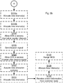
- Figs 4 and 5 are flow chart illustrating embodiments of methods for allocating access to a communications channel in a wireless communications network.
- the methods are performed by the processing unit 21.
- the methods are advantageously provided as computer programs 32.
- Fig 3 shows one example of a computer program product 31 comprising computer readable means 33.
- a computer program 32 can be stored, which computer program 32 can cause the processing unit 21 and thereto operatively coupled entities and devices, such as the communications interface 22 and the storage medium 23, to execute methods according to embodiments described herein.
- the computer program 32 and/or computer program product 31 may thus provide means for performing any steps as herein disclosed.
- the computer program product 31 is illustrated as an optical disc, such as a CD (compact disc) or a DVD (digital versatile disc) or a Blu-Ray disc.
- the computer program product 31 could also be embodied as a memory, such as a random access memory (RAM), a read-only memory (ROM), an erasable programmable read-only memory (EPROM), or an electrically erasable programmable read-only memory (EEPROM) and more particularly as a non-volatile storage medium of a device in an external memory such as a USB (Universal Serial Bus) memory.
- RAM random access memory
- ROM read-only memory
- EPROM erasable programmable read-only memory
- EEPROM electrically erasable programmable read-only memory
- the computer program 32 is here schematically shown as a track on the depicted optical disk, the computer program 32 can be stored in any way which is suitable for the computer program product 31.
- Fig 4 illustrating a method for allocating access to a communications channel in a wireless communications network 10a-c according to an embodiment.
- the method is performed by an access point (AP) 11a in the wireless communications network.
- the AP 11a is configured such that the stations (STAs) 12a, ...12f are associated with the AP 11a.
- the method comprises grouping, in a step S102, the STAs 12a-f of the AP 11a in at least two groups of STAs.
- Each group of STAs is associated with a minimum transmission power level needed by the AP to communicate with the STAs in that group.
- each group of STAs may be associated with a minimum transmission power level needed by the STAs in a group to communicate with the AP.
- the processing unit 21 of the AP 11a is configured to perform step S102, for example by implementing functionality of the group module 21a.
- the STAs 12a-f are grouped according to a power level criterion.
- the method comprises allocating, in a step S104, a first time interval for a first group of STAs.
- the first group of STAs is associated with highest minimum transmission power of the at least two groups of the AP 11a to access the communications channel.
- the first time interval is concurrent with a third time interval allocated by another AP 11b for a third group of STAs.
- the third group of STAs is associated with lowest minimum transmission power level needed by said another AP to communicate with the third group of STAs to access the communications channel.
- the processing unit 21 of the AP 11a is configured to perform step S104, for example by implementing functionality of the allocate module 21b.
- the method comprises allocating, in a step S106, a second time interval, non-overlapping with the first time interval, for a second group of STAs.
- the second group of STAs is associated with lowest minimum transmission power of the at least two groups of he AP 11a to access the communications channel.
- the second time interval is concurrent with a fourth time interval being allocated by said another AP for a fourth group of STAs.
- the fourth group of STAs is associated with highest minimum transmission power level needed by said another AP to communicate with the fourth group of STAs to access the communications channel.
- the processing unit 21 of the AP 11a is configured to perform step S106, for example by implementing functionality of the allocate module 21b.
- the method is based on two general principles.
- the first principle relates to conventional power control in the sense that a STA or AP should not transmit using higher transmit power than necessary.
- the second principle relates to coordinating the scheduling (i.e., the allocation of time intervals when STAs are allowed to access the communications channel) between different BSS such that the STAs that require high transmit power (either in DL, but even more in UL) are scheduled at different time instants. This allows for a reuse factor that effectively is close to one at the same time as it allows transmission to and from STAs with high transmit powers.
- access to the communications channel may be based on carrier sense multiple access with collision avoidance (CSMA/CA).
- CSMA/CA carrier sense multiple access with collision avoidance
- OFDMA Orthogonal Frequency-Division Multiple Access
- UL i.e., the transmission from a STA 12a-l to an AP 11a-b.
- the wireless communications network 10a-c may be a wireless local area network (WLAN).
- WLAN wireless local area network
- the herein disclosed methods are applicable for STAs operating in different modes.
- the STAs 12a-f of the AP 11a may be STAs in idle mode or in connected mode and being within a coverage area 17a of the AP 11a.
- STAs without power control may be grouped in the first group.
- the allocating in any of steps S104 and S106 may further be based on additional information, properties, etc.
- the allocating in any of steps S104 and S106 may based on at least one of location information, measured interference, and packet loss for the STAs of the AP. Further such additional information, properties, etc. will be disclosed below.
- FIG. 5 illustrating methods for allocating access to a communications channel in a wireless communications network according to further embodiments.
- allocating the first time interval in step S104 and the second time interval in step S106 may involve setting up time slots to at least some of the STAs of the AP 11a.
- the method may therefore comprise an optional step S108a of setting up time slots for when STAs in the first group are allowed to transmit; and/or an optional step S108b of setting up time slots for when STAs in the second group are allowed to transmit.
- the processing unit 21 of the AP 11a may be configured to perform any of steps S108a and S108b, for example by implementing functionality of the set up module 21c.
- allocating the first time interval in step S104 and the second time interval in step S106 may involve allowing at least some of the STAs of the AP 11a to respond to previous transmissions from the AP 11a.
- the method may therefore comprise an optional step S110 of allowing STAs in at least one of the first group and the second group to transmit at least one of an acknowledgement (ACK) report and a negative acknowledgement (NACK) report to the AP 11a.
- ACK acknowledgement
- NACK negative acknowledgement
- the processing unit 21 of the AP 11a may be configured to perform step S110, for example by implementing functionality of the allow module 21e.
- steps S104 and S106 may further be based on additional information, properties, etc. Further examples relating thereto will now be disclosed.
- the allocating may therefore be based on resource information.
- the method may therefore comprise an optional step S112a of acquiring resource information regarding a transmit resources need for the STAs of the AP; and an optional step S114a of allocating at least one of the first time interval and the second time interval based on the acquired resource information.
- the processing unit 21 of the AP 11a may be configured to perform any of steps S112a and S114a, for example by implementing functionality of the acquire module 21f and the allocate module 21b.
- the allocating may be based on allocation information.
- the method may therefore comprise an optional step S112b of acquiring allocation information regarding allocation of STAs of said another AP 11b from said another AP 11b; and an optional step S114b of allocating at least one of the first time interval and the second time interval based on the acquired allocation information.
- the processing unit 21 of the AP 11a may be configured to perform step any of steps S112b and S114b, for example by implementing functionality of the acquire module 21f and the allocate module 21b.
- the first time interval and/or the second time interval may be based on regular time intervals.
- the method may therefore comprise an optional step S116 of allowing STAs in at least one of the first group and the second group to access the communications channel at regular time intervals.
- the processing unit 21 of the AP 11a may be configured to perform step S116, for example by implementing functionality of the allow module 21e.
- the first time interval and/or the second time interval may be based on when in time a beacon signal is transmitted by one of the AP 11a and said another AP 11b
- the method may therefore comprise an optional step S118 of sending a beacon signal; and an optional step S120 of allowing STAs in at least one of the first group and the second group to access the communications channel after a predetermined time interval from when the beacon signal was sent.
- the processing unit 21 of the AP 11a may be configured to perform any of steps S122 and S124, for example by implementing functionality of the send/receive module 21d and the allow module 21e.
- the first time interval and/or the second time interval may be based on a time allocation pattern.
- the method may therefore comprise an optional step S122 of acquiring a time allocation pattern; and an optional step S124 of allocating at least one of the first time interval and the second time interval based on the acquired time allocation pattern.
- the processing unit 21 of the AP 11a may be configured to perform any of steps S122 and S124, for example by implementing functionality of the acquire module 21f and the allocate module 21b.
- the acquired time allocation pattern may be a courtesy contention window pattern (CCWP).
- the first time interval and/or the second time interval may be based on control information from a controller node 19.
- the method may therefore comprise an optional step S126 of receiving control information from a controller node 19; and an optional step S132 of allocating at least one of the first time interval and the second time interval based on the acquired control information.
- the processing unit 21 of the AP 11a may be configured to perform any of steps S126 and S128, for example by implementing functionality of the send/receive module 21d and the allocate module 21b.
- the method may comprise an optional step S130 of assigning a modulation and coding scheme (MCS) to at least one STA in the first group, thereby moving the at least one STA to the second group. For example, by assigning another MSC to at least one STA in the second group, the at least one STA may be moved to the first group.
- MCS modulation and coding scheme
- the processing unit 21 of the AP 11a may be configured to perform step S130, for example by implementing functionality of the assign module 21g.
- Fig 1b illustrating a situation with two APs 11a-b and a number of STAs 12a-l associated with a respective AP 11a-b.
- STAs 12a-f are associated with AP 11a
- STAs 12g-l are associated with AP 11b.
- AP 11a and STAs 12a-f thus form a BSS
- AP 11b and STAs 12g-l thus form another BSS.
- the dashed lines 16a, 16b illustrate the network coverage areas of an AP 11a-b in case a lower transmit power level is used (corresponding to a lowest minimum transmission power being needed by STAs to access the communications channel) and the solid lines 17a, 17b illustrate the network coverage areas in case a higher transmit power level is used (corresponding to a highest minimum transmission power being needed by STAs to access the communications channel).
- the first time interval is in step S104 allocated for a first group of STAs consisting of STA 12f for AP 11a; and the second time interval is in step S106 allocated for a second group of STAs consisting of STA 12a-e for AP 11a.
- the third group of STAs associated with AP 11b consists of STAs 12h-l; and the fourth group of STAs associated with AP 11b consists of STA 12g.
- the STAs that are close to respective AP 11a-b may be able to communicate as they may be able to ensure that the C/I is sufficiently large. This, however, still means that there are issues for the STAs that are far from respective AP 11a-b (in the illustrative example of Fig 1b these are STA 12f and STA 12g). Since DSC exploits that the C/I will be sufficiently larger although the interference, I, is large, DSC will not help for the STAs far from the APs.
- the above short-coming of DSC in the state of the art is circumvented by using coordinated power control as follows based at least on performing steps S102, S104, and S106 as disclosed above.
- AP 11a and AP 11b may exchange information concerning how much of the total time is needed for the STAs 12f, 12g that need to transmit at the higher transmission power and in addition agree on non-overlapping timeslots when STAs 12f, 12g in respective BSSs may use the higher transmission power.
- the relative size of the allocated time intervals for STAs in the different groups may therefore be based on the resource needs for the STAs associated with a time interval. For example, if the resource needs for low power STAs is much larger than that for high power STAs, the relative time allocated to low power STAs may be large compared to that allocated to the high power STAs. For the example, for illustrative and non-limiting purposes it is assumed that STA12f (belonging to AP 11a) needs 20% of the time, whereas STA 12g (of AP 11b) needs 25% of the time.
- the needed time may depend on the required throughput as well as what modulation and coding scheme (MCS) can be used.
- MCS modulation and coding scheme
- AP 11a and AP 11b may then determine a schedule with a period of e.g., 20 ms where AP 11a can schedule STA 12f during the first 4 ms of every such period, and where AP 11b can schedule STA 12g from 4 ms to 9 ms of every such period.
- Scheduling here implies setting up different time slots in which different devices of the wireless communications network are allowed to initiate a transmission by accessing the communications channel of the wireless communications network.
- the time slots may be set up by first performing the allocating as in steps S104 and S106.
- the AP 11a-b handling the schedule of transmit slots knows when to transmit to certain STAs 12a-l.
- STAs 12a-l For STAs 12a-l transmitting to the AP 11a-b they will be made aware of when they are allowed to perform such transmissions according to the schedule (or allocation) set up by the serving AP 11a-b (i.e., AP 11a for STAs 12a-f and AP 11b for STAs 12g-l). This information may be shared with the STAs 12a-l in different ways. Examples include, but are not limited to, direct scheduling commands from the AP 11a-b, signalling of the schedule by the AP 11a-b, signalling of the schedule relative to some other events, such as beacon frames, or other ways to determine the schedule based on parameters known by the STA 12a-l, for example in cases of pseudo random schedules.
- AP 11a may thus schedule STA 12f.
- AP 11a may also schedule any of the other STAs 12a-e if found beneficial for some reason.
- AP 11b may schedule any of STAs 12h-l, but may not schedule STA 12g since this would cause too low C/I for STA 12f and this period is aimed for protecting the transmission to STA 12f.
- AP 11b may schedule STA 12g.
- AP 11a may during this time schedule any STA except STA 12f, since STA 12f is transmitting at the higher transmission power and may thus disturb STA 12g currently being scheduled.
- the two APs 11a-b exchange information about, and agreed on when, higher output powers may be used.
- This first particular embodiment is also applicable to situations with more than two APs 11a, 11b, 11c, such as in the illustrative non-limiting example of Fig 1c .
- the APs 11a-c may communicate via a wired backhaul or by using wireless links.
- the time intervals allocated to STAs using the lower transmission power is not over lapping with the time intervals allocated for the STAs using the higher transmission power for the same AP.
- This is in contrast to the proposal in Oteri .
- One issue with the proposal in Oteri is that it will potentially cause a detrimental hidden node problem. As an example, suppose that all STAs 12a-f associated with AP 11a would be allowed to transmit during the same time interval. Since, for instance, STA 12c and STA 12e are far away from STA 12f, STA 12c and STA 12e may be hidden for STA 12f.
- the first particular embodiment may be implemented using restrictive access windows (RAWs), as described in IEEE 802.11ah, D1.2.
- RAWs restrictive access windows
- a first AP 11a is configured to schedule high power transmission (by performing step S104) at regular intervals, e.g. during 10ms directly following a beacon transmission.
- Other APs 11b-c may in this way predict when the high power transmissions associated with the BSS of AP 11a may occur and may select non-overlapping time intervals for using the higher output power, e.g. the 10ms directly following the time interval selected by the first AP 11a.
- the different APs 11a-c are configured to use specific pattern for when they are allowed to use certain output powers. For instance, in case of only two power levels, an AP 11a-c may use the higher output power only during certain time instants. Such a pattern may be a courtesy contention window pattern, CCWP. These patterns may be selected such that the patterns for each AP 11a-c overlap as little as possible. As a specific example, it is for illustrative and non-limiting purposes assumed that an AP 11a-c is allowed to use the higher output power during two 5 ms slots between every two beacon transmissions (100 ms).
- the AP 11a-c uses two slots that may be selected in a pseudo random fashion (according, for example according to the CCWP). If several APs 11a-c potentially interfere with one another, the APs 11a-c may use different CCWPs.
- the CCWPs pattern may be determined such that when the pattern indicate that a high transmission power may be used by a STAs associated with a specific AP, then the STAs only allowed to use the lower output power are not allowed to contend for the communications channel in order to avoid the hidden node problem.
- the CCWPs can be made perfectly orthogonal such that the time intervals do not overlap. For the example above with 20 slots and two slots for each AP 11a-c, this means that 10 APs 11a-c may be supported with perfectly orthogonal CCWPs. When the number of needed slots is larger, the CCWPs may not be perfectly orthogonal, but instead the CCWPs may be determined such that they overlap as little as possible.
- the CCWP may for example be based on so-called Gold Sequences (or Gold Codes), which are sometime used in spread spectrum systems.
- the different APs 11a-c may be provided with a suitable CCWP from a controller node 19.
- the APs 11a-c may themselves determine suitable CCWP patterns.
- the CCWPs may be selected at random, or an AP 11a-c may try to determine what CCWP patterns are already used by overlapping BSSs, and based on this select a suitable CCWP.
- Another possibility in the non-controlled deployment is for each AP 11a-b to distribute its CCWP to all other APs 11a-c.
- each particular AP 11a-c may be configured to optimize a new CCWP based on transmission and/or reception requirements for STAs associated with the particular AP or based on such requirements for the particular AP itself.
- This new CCWP may again be distributed to all other APs 11a-c. This procedure may be iterated a predetermined number of times, or until some value representing the optimization of CCWP has converged to a limit.
- the coordination has been performed amongst the APs 11a-c, and optionally by a controller node 19. All the above disclosed particular embodiments may be regarded as being concerned with the actual scheduling. There may be different ways for the APs 11a-c, or optionally the controller node 19, to obtain information needed for this scheduling; all of the above disclosed particular embodiments are applicable regardless of how this information is obtained. As one example, the information may be collected by the APs 11a-c without any input from the involved STAs 12a-l. As another example, information from one or several STAs 12a-l may be used in addition or alternatively to the information directly available at the AP 11a-c.
- these STAs 12a-l may preferably be put in the group using the highest output power. If the number of STAs 12a-l not supporting power control is large, this may imply that these groups will become larger and make the scheduling more difficult. For example, either it may need to be accepted that there will be transmissions where more than one AP 11a-c schedule high power STAs, or it may need to be accepted that the high power STAs will be given less time for transmission. This approach is applicable for all of the above disclosed particular embodiments.
- Fig 1c schematically illustrates a communications system 10c.
- STA 12a-e are associated with AP 11a
- STA g-j are associated with AP 11b
- STA m-n are associated with AP 11c.
- STA 12b, STA 12j, and STA 12m are sufficiently close to their respective AP 11a-c to us a lower transmission power, whereas the other STAs need to use a higher output power.
- Fig 1c is also schematically illustrated a further, intermediate power level, as represented by the network coverage areas 18a, 18b, 18c.
- STA 12c may be enable to access the communications channel using a transmission power being lower than the highest minimum transmission power level and higher than the lowest minimum transmission power level.
- STA 12c may be grouped in a further group being associated with an intermediate minimum transmission power level needed by the AP 11a to communicate with the STA 12c in that group.
- This further group of STAs may be allocated a further time interval for accessing the communications channel. This further time interval may be non-overlapping with at least one of the first time interval and the second time interval.
- STA 12d will only cause interference to the BSS represented by AP 11c; and STA 12e will only cause interference to the BSS represented by AP 11b. Consequently, it would be possible to allow at least some of the high power STAs 12a, 12d, 12e, 12g, 12h, 12n to in some cases transmit concurrently (or simultaneously).
- this information may, for example, be used to give 50% of the high power time to the BSS represented by AP 11a and 50% of the high transmission power time to the BSS represented by AP 11b, and in addition allowing STA 12b to transmit during the high power time interval of the BSS represented by AP 11b.
- the BSS represented by AP 11a could be active 100% of the time and the BSS represented by AP 11b could be active 50% of the time. This means that in total, the high power STAs effectively would be allowed more than 100% airtime. Without this information, whatever the actual scheduling, the 100% needs to be shared among the high power STAs.
- not only the required power is considered when scheduling the STAs 12a-n, but also information about how STAs12a-may potentially interfere with each other.
- this information may be obtained. Examples of how this information may be obtained include, but are not limited to, direct measurements of the interference levels that different STAs 12a-n cause to one another, and by obtaining information of the locations of the STAs 12a-n (in which case the path loss may be estimated and through this the interference may be estimated). Information may also be obtained indirectly by monitoring packet loss through collisions and in that way correlate when certain STAs 12a-n transmit and when collisions take place at specific STAs 12a-n.
- the STAs 12a-n have been divided in two groups; high power STAs and low power STAs, and then scheduling among the APs 11a-c for when the high power STAs are allowed transmit (and when corresponding APs can transmit with high power) has been performed.
- the time interval when a specific AP 11a-c is not allowed to use the highest transmission power was then allocated to the STAs using the lower output power. In Oteri this is done differently in that the low power STAs are allowed to access the channel at all times.
- the APs 11a-c also takes this information into account when grouping the STAs into high power STAs and low power STAs. Specifically, in case the required capacity for the high power STAs cannot be met, the APs 11a-c may be configured to change one or more of the high power STAs into low power STAs by mandating a lower MCS so that the wireless link between such STAs and the AP can be maintained but with a lower Signal-to-interference-ratio (SIR). Changing the allocated timing of high power STAs versus low power STAs may also be an option, but may require coordination between the BSSs. According to the fifth particular embodiment, there is not a direct relation between the needed transmission power and the path loss, but rather there is direct relation between the needed transmission power and the required received power, which in turn will depend on the selected MCS.
- SIR Signal-to-interference-ratio
- AP and STA has bee used to denote the network node (base station) and the mobile stations (user equipment; UE), respectively.
- AP Access Point
- STA Station
- the herein disclosed embodiments are not limited to this standard, but may be applied also to other standards, mutatis mutandis.
- PHY physical layer
- OFDM orthogonal frequency division multiplexing
- DSSS direct sequence spread spectrum
- Signalling needed for ensuring that the STAs do transmit at suitable time is transmitted from the AP to the STAs.
- the signalling may be provided in each packet, e.g. the MAC header of the packet, but it may also be transmitted less frequent, e.g. by the AP sending dedicated control packets, either to STAs individually or using e.g. multi-cast.
Landscapes
- Engineering & Computer Science (AREA)
- Computer Networks & Wireless Communication (AREA)
- Signal Processing (AREA)
- Mobile Radio Communication Systems (AREA)
Claims (19)
- Verfahren zur Zuweisung von Zugriff auf einen Kommunikationskanal in einem drahtlosen Kommunikationsnetzwerk (10a, 10b, 10c), wobei das Verfahren von einem Zugangspunkt, AP, (11a) im drahtlosen Kommunikationsnetzwerk und assoziierten Stationen, STAs, (12a, ...12f) durchgeführt wird und die folgenden Schritte umfasst:Einteilen (S102) der STAs des APs in mindestens zwei Gruppen von STAs, wobei jede Gruppe mit einem Mindest-Sendeleistungspegel assoziiert ist, der vom AP zum Kommunizieren mit den STAs in dieser Gruppe benötigt wird;Zuweisen (S104) eines ersten Zeitintervalls für eine erste Gruppe von STAs, die mit der höchsten Mindest-Sendeleistung assoziiert ist, um auf den Kommunikationskanal zuzugreifen, gleichzeitig mit einem dritten Zeitintervall, das von einem anderen AP (11b) für eine dritte Gruppe von STAs zugewiesen wird, die mit dem niedrigsten Mindest-Sendeleistungspegel assoziiert ist, der vom anderen AP zum Kommunizieren mit der dritten Gruppe von STAs benötigt wird, um auf den Kommunikationskanal zuzugreifen; undZuweisen (S106) eines zweiten, sich mit dem ersten Zeitintervall nicht überlappenden Zeitintervalls für eine zweite Gruppe von STAs, die mit der niedrigsten Mindest-Sendeleistung assoziiert ist, um auf den Kommunikationskanal zuzugreifen, gleichzeitig mit einem vierten Zeitintervall, das vom anderen AP (11b) für eine vierte Gruppe von STAs zugewiesen wird, die mit dem höchsten Mindest-Sendeleistungspegel assoziiert ist, der vom anderen AP zum Kommunizieren mit der vierten Gruppe von STAs benötigt wird, um auf den Kommunikationskanal zuzugreifen.
- Verfahren nach Anspruch 1, ferner umfassend:Festlegen von Zeitschlitzen (S108a), in welchen STAs in der ersten Gruppe senden dürfen; und/oderFestlegen von Zeitschlitzen (S108b), in welchen STAs in der zweiten Gruppe senden dürfen.
- Verfahren nach Anspruch 1, ferner umfassend:Zulassen (S110), dass STAs in mindestens einer von der ersten Gruppe und der zweiten Gruppe mindestens eine von einer Bestätigungs, ACK,-Meldung und einer Negativbestätigungs, NACK,-Meldung an den AP senden.
- Verfahren nach Anspruch 1, ferner umfassend:Einholen (S112a) von Ressourceninformationen hinsichtlich eines Senderessourcenbedarfs für die STAs des APs; und:Zuweisen (S114a) mindestens eines von dem ersten Zeitintervall und dem zweiten Zeitintervall basierend auf den eingeholten Ressourceninformationen.
- Verfahren nach Anspruch 1, ferner umfassend:Einholen (S112b) von Zuweisungsinformationen hinsichtlich einer Zuweisung von STAs des anderen APS vom anderen AP; und:Zuweisen (S114a) mindestens eines von dem ersten Zeitintervall und dem zweiten Zeitintervall basierend auf den eingeholten Dispositionsinformationen.
- Verfahren nach Anspruch 1, ferner umfassend:Zulassen (S116), dass STAs in mindestens einer von der ersten Gruppe und der zweiten Gruppe in regelmäßigen Intervallen auf den Kommunikationskanal zugreifen.
- Verfahren nach Anspruch 1, ferner umfassend:Senden (S118) eines Bakensignals; undZulassen (S120), dass STAs in mindestens einer von der ersten Gruppe und der zweiten Gruppe nach einem vorbestimmten Zeitintervall ab dem Sendezeitpunkt des Bakensignals auf den Kommunikationskanal zugreifen.
- Verfahren nach Anspruch 1, ferner umfassend:Einholen (S122) eines Zeitzuweisungsmusters; undZuweisen (S124) mindestens eines von dem ersten Zeitintervall und dem zweiten Zeitintervall basierend auf dem eingeholten Zeitzuweisungsmuster.
- Verfahren nach Anspruch 8, wobei das Zeitzuweisungsmuster ein Höflichkeitskonfliktfenstermuster, CCWP, ist.
- Verfahren nach Anspruch 1, ferner umfassend:Empfangen (S126) von Steuerinformationen von einem Steuerungsknoten; undZuweisen (S114a) mindestens eines von dem ersten Zeitintervall und dem zweiten Zeitintervall basierend auf den eingeholten Steuerinformationen.
- Verfahren nach Anspruch 1, wobei STAs ohne Leistungssteuerung in die erste Gruppe eingeteilt werden.
- Verfahren nach Anspruch 1, wobei das Zuweisen ferner auf mindestens einem von Standortinformationen, gemessener Interferenz oder Paketverlust für die STAs des APs basiert.
- Verfahren nach Anspruch 1, ferner umfassend:Zuordnen (S130) eines Modulations- und Codierungsschemas, MCS, zu mindestens einer STA in der ersten Gruppe, um dadurch die mindestens eine STA in die zweite Gruppe zu verlegen.
- Verfahren nach Anspruch 1, wobei der Zugriff auf den Kommunikationskanal auf Vielfachzugriff mit Trägerkennung und mit Kollisionsvermeidung, CSMA/CA, basiert.
- Verfahren nach Anspruch 1, wobei das drahtlose Kommunikationsnetzwerk ein drahtloses lokales Netzwerk, WLAN, ist.
- Verfahren nach Anspruch 1, wobei die STAs des APs STAs im Ruhemodus oder im angeschlossenen Modus und innerhalb des Versorgungsgebiets (17a) des APs sind.
- Zugangspunkt, AP, (11a) zum Zuweisen von Zugriff auf einen Kommunikationskanal in einem drahtlosen Kommunikationsnetzwerk (10a, 10b, 10c), wobei der AP eine Verarbeitungseinheit (21) umfasst, die konfiguriert ist zum:Einteilen von STAs, die mit dem AP assoziiert sind, in mindestens zwei Gruppen von STAs, (12a-f) wobei jede Gruppe mit einem Mindest-Sendeleistungspegel assoziiert ist, der vom AP zum Kommunizieren mit den STAs in dieser Gruppe benötigt wird;Zuweisen eines ersten Zeitintervalls für eine erste Gruppe von STAs, die mit der höchsten Mindest-Sendeleistung assoziiert ist, um auf den Kommunikationskanal zuzugreifen, gleichzeitig mit einem dritten Zeitintervall, das von einem anderen AP (11b) für eine dritte Gruppe von STAs zugewiesen wird, die mit dem niedrigsten Mindest-Sendeleistungspegel assoziiert ist, der vom anderen AP zum Kommunizieren mit der dritten Gruppe von STAs benötigt wird, um auf den Kommunikationskanal zuzugreifen; undZuweisen eines zweiten, sich mit dem ersten Zeitintervall nicht überlappenden Zeitintervalls für eine zweite Gruppe von STAs, die mit der niedrigsten Mindest-Sendeleistung assoziiert ist, um auf den Kommunikationskanal zuzugreifen, gleichzeitig mit einem vierten Zeitintervall, das von einem anderen AP (11b) für eine vierte Gruppe von STAs zugewiesen wird, die mit dem höchsten Mindest-Sendeleistungspegel assoziiert ist, der vom anderen AP zum Kommunizieren mit der vierten Gruppe von STAs benötigt wird, um auf den Kommunikationskanal zuzugreifen.
- Computerprogramm (32) zum Zuweisen von Zugriff auf einen Kommunikationskanal in einem drahtlosen Kommunikationsnetzwerk (10a, 10b, 10c), wobei das Computerprogramm Computercode umfasst, der bei Ausführung auf einer Verarbeitungseinheit (21) in einem Zugangspunkt, AP, die Verarbeitungseinheit veranlasst zum:Einteilen (S102) von Stationen, STAs, (12a-f), die mit einem Zugangspunkt, AP, (11a) assoziiert sind, in mindestens zwei Gruppen von STAs, wobei jede Gruppe mit einem Mindest-Sendeleistungspegel assoziiert ist, der vom AP zum Kommunizieren mit den STAs in dieser Gruppe benötigt wird;Zuweisen (S104) eines ersten Zeitintervalls für eine erste Gruppe von STAs, die mit der höchsten Mindest-Sendeleistung assoziiert ist, um auf den Kommunikationskanal zuzugreifen, gleichzeitig mit einem dritten Zeitintervall, das von einem anderen AP (11b) für eine dritte Gruppe von STAs zugewiesen wird, die mit dem niedrigsten Mindest-Sendeleistungspegel assoziiert ist, der vom anderen AP zum Kommunizieren mit der dritten Gruppe von STAs benötigt wird, um auf den Kommunikationskanal zuzugreifen; undZuweisen (S106) eines zweiten, sich mit dem ersten Zeitintervall nicht überlappenden Zeitintervalls für eine zweite Gruppe von STAs, die mit der niedrigsten Mindest-Sendeleistung assoziiert ist, um auf den Kommunikationskanal zuzugreifen, gleichzeitig mit einem vierten Zeitintervall, das von einem anderen AP (11b) für eine vierte Gruppe von STAs zugewiesen wird, die mit dem höchsten Mindest-Sendeleistungspegel assoziiert ist, der vom anderen AP zum Kommunizieren mit der vierten Gruppe von STAs benötigt wird, um auf den Kommunikationskanal zuzugreifen.
- Computerprogrammprodukt (31), umfassend ein Computerprogramm (32) nach Anspruch 18 und ein computerlesbares Mittel (33), auf welchem das Computerprogramm gespeichert ist.
Applications Claiming Priority (1)
| Application Number | Priority Date | Filing Date | Title |
|---|---|---|---|
| PCT/EP2014/059615 WO2015172805A1 (en) | 2014-05-12 | 2014-05-12 | Access to a communications channel in a wireless communications network |
Publications (2)
| Publication Number | Publication Date |
|---|---|
| EP3143790A1 EP3143790A1 (de) | 2017-03-22 |
| EP3143790B1 true EP3143790B1 (de) | 2018-03-21 |
Family
ID=50687502
Family Applications (1)
| Application Number | Title | Priority Date | Filing Date |
|---|---|---|---|
| EP14723084.1A Active EP3143790B1 (de) | 2014-05-12 | 2014-05-12 | Zugriff auf einen kommunikationskanal in einem drahtloskommunikationsnetzwerk |
Country Status (5)
| Country | Link |
|---|---|
| US (1) | US10342041B2 (de) |
| EP (1) | EP3143790B1 (de) |
| JP (1) | JP6387115B2 (de) |
| BR (1) | BR112016026108B1 (de) |
| WO (1) | WO2015172805A1 (de) |
Families Citing this family (11)
| Publication number | Priority date | Publication date | Assignee | Title |
|---|---|---|---|---|
| US10257806B2 (en) * | 2013-11-11 | 2019-04-09 | Marvell World Trade Ltd. | Medium access control for multi-channel OFDM in a wireless local area network |
| US10425937B2 (en) * | 2014-06-22 | 2019-09-24 | Lg Electronics Inc. | Method and apparatus for transmitting and receiving signal by full-duplex base station in wireless communication system |
| US10257840B2 (en) | 2014-10-22 | 2019-04-09 | Telefonaktiebolaget Lm Ericsson (Publ) | Operation of wireless local area network in the presence of periodic interference |
| WO2016086366A1 (zh) * | 2014-12-03 | 2016-06-09 | 华为技术有限公司 | 使用频谱资源进行通信的方法和通信设备 |
| CN105101432B (zh) * | 2015-05-29 | 2018-09-14 | 珠海市魅族科技有限公司 | 一种无线通信方法及设备 |
| US11038566B2 (en) | 2017-01-06 | 2021-06-15 | Telefonaktiebolaget Lm Ericsson (Publ) | Precoding a transmission from a multi-panel antenna array |
| JP7188729B2 (ja) * | 2018-03-02 | 2022-12-13 | 株式会社国際電気通信基礎技術研究所 | 無線通信方法、および、プログラム |
| JP7022965B2 (ja) * | 2018-07-04 | 2022-02-21 | 日本電信電話株式会社 | 無線通信システム、無線通信方法および無線基地局 |
| US11202288B2 (en) * | 2019-09-06 | 2021-12-14 | Cisco Technology, Inc. | Forming channel device groups within a citizens broadband radio service band |
| US11690083B2 (en) | 2020-06-09 | 2023-06-27 | Qualcomm Incorporated | Grouping user equipment based on downlink power |
| US11627574B2 (en) | 2020-06-09 | 2023-04-11 | Qualcomm Incorporated | Grouping user equipment based on downlink power |
Family Cites Families (9)
| Publication number | Priority date | Publication date | Assignee | Title |
|---|---|---|---|---|
| GB0420658D0 (en) * | 2004-09-16 | 2004-10-20 | Nokia Corp | Scheduling data transmissions in a wireless communications network |
| US20070291702A1 (en) * | 2004-10-19 | 2007-12-20 | Hideo Nanba | Base Station Apparatus,Wireless Communication System,And Wireless Transmission Method |
| CN101043693B (zh) | 2006-03-23 | 2011-05-11 | 华为技术有限公司 | 一种在小区间消除干扰的方法及系统 |
| JP2008160182A (ja) * | 2006-12-20 | 2008-07-10 | Toshiba Corp | 無線通信機システムおよびその無線通信シーケンス |
| WO2010050899A1 (en) * | 2008-10-28 | 2010-05-06 | Agency For Science, Technology And Research | A method of optimising bandwidth allocation in a wireless communication network |
| FR2949928A1 (fr) * | 2009-09-08 | 2011-03-11 | Thomson Licensing | Procede d'emission mis en œuvre par un nœud et procede de reception correspondant |
| US9031032B2 (en) | 2009-10-05 | 2015-05-12 | Futurewei Technologies, Inc. | System and method for inter-cell interference coordination |
| JP5687997B2 (ja) * | 2011-11-10 | 2015-03-25 | 日本電信電話株式会社 | 無線通信システム |
| JP5503627B2 (ja) * | 2011-12-02 | 2014-05-28 | 株式会社日立製作所 | 無線通信システム及び方法、基地局装置 |
-
2014
- 2014-05-12 EP EP14723084.1A patent/EP3143790B1/de active Active
- 2014-05-12 BR BR112016026108-9A patent/BR112016026108B1/pt active IP Right Grant
- 2014-05-12 WO PCT/EP2014/059615 patent/WO2015172805A1/en active Application Filing
- 2014-05-12 US US15/310,748 patent/US10342041B2/en active Active
- 2014-05-12 JP JP2016567248A patent/JP6387115B2/ja active Active
Also Published As
| Publication number | Publication date |
|---|---|
| WO2015172805A1 (en) | 2015-11-19 |
| US20170086224A1 (en) | 2017-03-23 |
| BR112016026108A2 (de) | 2017-08-15 |
| JP2017516403A (ja) | 2017-06-15 |
| EP3143790A1 (de) | 2017-03-22 |
| JP6387115B2 (ja) | 2018-09-05 |
| US10342041B2 (en) | 2019-07-02 |
| BR112016026108B1 (pt) | 2023-02-23 |
Similar Documents
| Publication | Publication Date | Title |
|---|---|---|
| EP3143790B1 (de) | Zugriff auf einen kommunikationskanal in einem drahtloskommunikationsnetzwerk | |
| US10548157B2 (en) | Unlicensed spectrum scheduling method and device, and user equipment UE | |
| EP2992625B1 (de) | Kanalsatzzuteilung in einer frequenz-multiplexierten kommunikation in dichten drahtlosen umgebungen | |
| EP2992729B1 (de) | Verfahren, vorrichtungen und computerprogramm für peer-to-peer- und ap-multiplexing | |
| US9622249B2 (en) | Apparatus and method to set a control channel configuration in a communication system | |
| US20130136013A1 (en) | Handshaking Protocol Using Bursts in OFDMA Frame Structure | |
| CN117939607A (zh) | 跨基本服务集(bss)控制发射功率 | |
| US20220232580A1 (en) | User Device and Method with Beam Management Enhancements | |
| CA3109422C (en) | Network-assisted clear channel assessment bandwidth adaptation mechanism | |
| CN110313191B (zh) | 先说后听过程的重新配置 | |
| WO2017153630A1 (en) | Protecting transmissions in wireless network | |
| JP2020123815A (ja) | 無線基地局および無線通信方法 | |
| Saurav | Support for LTE operation in unlicensed bands |
Legal Events
| Date | Code | Title | Description |
|---|---|---|---|
| PUAI | Public reference made under article 153(3) epc to a published international application that has entered the european phase |
Free format text: ORIGINAL CODE: 0009012 |
|
| 17P | Request for examination filed |
Effective date: 20161123 |
|
| AK | Designated contracting states |
Kind code of ref document: A1 Designated state(s): AL AT BE BG CH CY CZ DE DK EE ES FI FR GB GR HR HU IE IS IT LI LT LU LV MC MK MT NL NO PL PT RO RS SE SI SK SM TR |
|
| AX | Request for extension of the european patent |
Extension state: BA ME |
|
| RIN1 | Information on inventor provided before grant (corrected) |
Inventor name: MESTANOV, FILIP Inventor name: LINDHEIMER, CHRISTOFER Inventor name: NILSSON, THOMAS Inventor name: SOEDER, JOHAN Inventor name: HIERTZ, GUIDO Inventor name: WANG, MENG Inventor name: KAPETANOVIC, DZEVDAN Inventor name: NORDSTROEM, ERIC Inventor name: WILHELMSSON, LEIF Inventor name: PERSSON, HAKAN |
|
| DAX | Request for extension of the european patent (deleted) | ||
| GRAP | Despatch of communication of intention to grant a patent |
Free format text: ORIGINAL CODE: EPIDOSNIGR1 |
|
| INTG | Intention to grant announced |
Effective date: 20171103 |
|
| GRAS | Grant fee paid |
Free format text: ORIGINAL CODE: EPIDOSNIGR3 |
|
| GRAA | (expected) grant |
Free format text: ORIGINAL CODE: 0009210 |
|
| AK | Designated contracting states |
Kind code of ref document: B1 Designated state(s): AL AT BE BG CH CY CZ DE DK EE ES FI FR GB GR HR HU IE IS IT LI LT LU LV MC MK MT NL NO PL PT RO RS SE SI SK SM TR |
|
| REG | Reference to a national code |
Ref country code: GB Ref legal event code: FG4D |
|
| REG | Reference to a national code |
Ref country code: CH Ref legal event code: EP |
|
| REG | Reference to a national code |
Ref country code: AT Ref legal event code: REF Ref document number: 982400 Country of ref document: AT Kind code of ref document: T Effective date: 20180415 |
|
| REG | Reference to a national code |
Ref country code: IE Ref legal event code: FG4D |
|
| REG | Reference to a national code |
Ref country code: DE Ref legal event code: R096 Ref document number: 602014022602 Country of ref document: DE |
|
| REG | Reference to a national code |
Ref country code: FR Ref legal event code: PLFP Year of fee payment: 5 |
|
| REG | Reference to a national code |
Ref country code: NL Ref legal event code: MP Effective date: 20180321 |
|
| PG25 | Lapsed in a contracting state [announced via postgrant information from national office to epo] |
Ref country code: HR Free format text: LAPSE BECAUSE OF FAILURE TO SUBMIT A TRANSLATION OF THE DESCRIPTION OR TO PAY THE FEE WITHIN THE PRESCRIBED TIME-LIMIT Effective date: 20180321 Ref country code: LT Free format text: LAPSE BECAUSE OF FAILURE TO SUBMIT A TRANSLATION OF THE DESCRIPTION OR TO PAY THE FEE WITHIN THE PRESCRIBED TIME-LIMIT Effective date: 20180321 Ref country code: NO Free format text: LAPSE BECAUSE OF FAILURE TO SUBMIT A TRANSLATION OF THE DESCRIPTION OR TO PAY THE FEE WITHIN THE PRESCRIBED TIME-LIMIT Effective date: 20180621 Ref country code: FI Free format text: LAPSE BECAUSE OF FAILURE TO SUBMIT A TRANSLATION OF THE DESCRIPTION OR TO PAY THE FEE WITHIN THE PRESCRIBED TIME-LIMIT Effective date: 20180321 Ref country code: CY Free format text: LAPSE BECAUSE OF FAILURE TO SUBMIT A TRANSLATION OF THE DESCRIPTION OR TO PAY THE FEE WITHIN THE PRESCRIBED TIME-LIMIT Effective date: 20180321 |
|
| REG | Reference to a national code |
Ref country code: LT Ref legal event code: MG4D |
|
| REG | Reference to a national code |
Ref country code: AT Ref legal event code: MK05 Ref document number: 982400 Country of ref document: AT Kind code of ref document: T Effective date: 20180321 |
|
| PG25 | Lapsed in a contracting state [announced via postgrant information from national office to epo] |
Ref country code: GR Free format text: LAPSE BECAUSE OF FAILURE TO SUBMIT A TRANSLATION OF THE DESCRIPTION OR TO PAY THE FEE WITHIN THE PRESCRIBED TIME-LIMIT Effective date: 20180622 Ref country code: SE Free format text: LAPSE BECAUSE OF FAILURE TO SUBMIT A TRANSLATION OF THE DESCRIPTION OR TO PAY THE FEE WITHIN THE PRESCRIBED TIME-LIMIT Effective date: 20180321 Ref country code: LV Free format text: LAPSE BECAUSE OF FAILURE TO SUBMIT A TRANSLATION OF THE DESCRIPTION OR TO PAY THE FEE WITHIN THE PRESCRIBED TIME-LIMIT Effective date: 20180321 Ref country code: RS Free format text: LAPSE BECAUSE OF FAILURE TO SUBMIT A TRANSLATION OF THE DESCRIPTION OR TO PAY THE FEE WITHIN THE PRESCRIBED TIME-LIMIT Effective date: 20180321 Ref country code: BG Free format text: LAPSE BECAUSE OF FAILURE TO SUBMIT A TRANSLATION OF THE DESCRIPTION OR TO PAY THE FEE WITHIN THE PRESCRIBED TIME-LIMIT Effective date: 20180621 |
|
| PG25 | Lapsed in a contracting state [announced via postgrant information from national office to epo] |
Ref country code: RO Free format text: LAPSE BECAUSE OF FAILURE TO SUBMIT A TRANSLATION OF THE DESCRIPTION OR TO PAY THE FEE WITHIN THE PRESCRIBED TIME-LIMIT Effective date: 20180321 Ref country code: IT Free format text: LAPSE BECAUSE OF FAILURE TO SUBMIT A TRANSLATION OF THE DESCRIPTION OR TO PAY THE FEE WITHIN THE PRESCRIBED TIME-LIMIT Effective date: 20180321 Ref country code: AL Free format text: LAPSE BECAUSE OF FAILURE TO SUBMIT A TRANSLATION OF THE DESCRIPTION OR TO PAY THE FEE WITHIN THE PRESCRIBED TIME-LIMIT Effective date: 20180321 Ref country code: PL Free format text: LAPSE BECAUSE OF FAILURE TO SUBMIT A TRANSLATION OF THE DESCRIPTION OR TO PAY THE FEE WITHIN THE PRESCRIBED TIME-LIMIT Effective date: 20180321 Ref country code: NL Free format text: LAPSE BECAUSE OF FAILURE TO SUBMIT A TRANSLATION OF THE DESCRIPTION OR TO PAY THE FEE WITHIN THE PRESCRIBED TIME-LIMIT Effective date: 20180321 Ref country code: ES Free format text: LAPSE BECAUSE OF FAILURE TO SUBMIT A TRANSLATION OF THE DESCRIPTION OR TO PAY THE FEE WITHIN THE PRESCRIBED TIME-LIMIT Effective date: 20180321 Ref country code: EE Free format text: LAPSE BECAUSE OF FAILURE TO SUBMIT A TRANSLATION OF THE DESCRIPTION OR TO PAY THE FEE WITHIN THE PRESCRIBED TIME-LIMIT Effective date: 20180321 |
|
| PG25 | Lapsed in a contracting state [announced via postgrant information from national office to epo] |
Ref country code: AT Free format text: LAPSE BECAUSE OF FAILURE TO SUBMIT A TRANSLATION OF THE DESCRIPTION OR TO PAY THE FEE WITHIN THE PRESCRIBED TIME-LIMIT Effective date: 20180321 Ref country code: SM Free format text: LAPSE BECAUSE OF FAILURE TO SUBMIT A TRANSLATION OF THE DESCRIPTION OR TO PAY THE FEE WITHIN THE PRESCRIBED TIME-LIMIT Effective date: 20180321 Ref country code: CZ Free format text: LAPSE BECAUSE OF FAILURE TO SUBMIT A TRANSLATION OF THE DESCRIPTION OR TO PAY THE FEE WITHIN THE PRESCRIBED TIME-LIMIT Effective date: 20180321 Ref country code: SK Free format text: LAPSE BECAUSE OF FAILURE TO SUBMIT A TRANSLATION OF THE DESCRIPTION OR TO PAY THE FEE WITHIN THE PRESCRIBED TIME-LIMIT Effective date: 20180321 |
|
| REG | Reference to a national code |
Ref country code: CH Ref legal event code: PL |
|
| PG25 | Lapsed in a contracting state [announced via postgrant information from national office to epo] |
Ref country code: PT Free format text: LAPSE BECAUSE OF FAILURE TO SUBMIT A TRANSLATION OF THE DESCRIPTION OR TO PAY THE FEE WITHIN THE PRESCRIBED TIME-LIMIT Effective date: 20180723 |
|
| REG | Reference to a national code |
Ref country code: DE Ref legal event code: R097 Ref document number: 602014022602 Country of ref document: DE |
|
| PLBE | No opposition filed within time limit |
Free format text: ORIGINAL CODE: 0009261 |
|
| STAA | Information on the status of an ep patent application or granted ep patent |
Free format text: STATUS: NO OPPOSITION FILED WITHIN TIME LIMIT |
|
| REG | Reference to a national code |
Ref country code: BE Ref legal event code: MM Effective date: 20180531 |
|
| PG25 | Lapsed in a contracting state [announced via postgrant information from national office to epo] |
Ref country code: DK Free format text: LAPSE BECAUSE OF FAILURE TO SUBMIT A TRANSLATION OF THE DESCRIPTION OR TO PAY THE FEE WITHIN THE PRESCRIBED TIME-LIMIT Effective date: 20180321 Ref country code: MC Free format text: LAPSE BECAUSE OF FAILURE TO SUBMIT A TRANSLATION OF THE DESCRIPTION OR TO PAY THE FEE WITHIN THE PRESCRIBED TIME-LIMIT Effective date: 20180321 |
|
| REG | Reference to a national code |
Ref country code: IE Ref legal event code: MM4A |
|
| 26N | No opposition filed |
Effective date: 20190102 |
|
| PG25 | Lapsed in a contracting state [announced via postgrant information from national office to epo] |
Ref country code: LI Free format text: LAPSE BECAUSE OF NON-PAYMENT OF DUE FEES Effective date: 20180531 Ref country code: CH Free format text: LAPSE BECAUSE OF NON-PAYMENT OF DUE FEES Effective date: 20180531 |
|
| PG25 | Lapsed in a contracting state [announced via postgrant information from national office to epo] |
Ref country code: LU Free format text: LAPSE BECAUSE OF NON-PAYMENT OF DUE FEES Effective date: 20180512 |
|
| PG25 | Lapsed in a contracting state [announced via postgrant information from national office to epo] |
Ref country code: IE Free format text: LAPSE BECAUSE OF NON-PAYMENT OF DUE FEES Effective date: 20180512 |
|
| PG25 | Lapsed in a contracting state [announced via postgrant information from national office to epo] |
Ref country code: BE Free format text: LAPSE BECAUSE OF NON-PAYMENT OF DUE FEES Effective date: 20180531 Ref country code: SI Free format text: LAPSE BECAUSE OF FAILURE TO SUBMIT A TRANSLATION OF THE DESCRIPTION OR TO PAY THE FEE WITHIN THE PRESCRIBED TIME-LIMIT Effective date: 20180321 |
|
| PG25 | Lapsed in a contracting state [announced via postgrant information from national office to epo] |
Ref country code: MT Free format text: LAPSE BECAUSE OF NON-PAYMENT OF DUE FEES Effective date: 20180512 |
|
| PG25 | Lapsed in a contracting state [announced via postgrant information from national office to epo] |
Ref country code: TR Free format text: LAPSE BECAUSE OF FAILURE TO SUBMIT A TRANSLATION OF THE DESCRIPTION OR TO PAY THE FEE WITHIN THE PRESCRIBED TIME-LIMIT Effective date: 20180321 |
|
| PG25 | Lapsed in a contracting state [announced via postgrant information from national office to epo] |
Ref country code: MK Free format text: LAPSE BECAUSE OF NON-PAYMENT OF DUE FEES Effective date: 20180321 Ref country code: HU Free format text: LAPSE BECAUSE OF FAILURE TO SUBMIT A TRANSLATION OF THE DESCRIPTION OR TO PAY THE FEE WITHIN THE PRESCRIBED TIME-LIMIT; INVALID AB INITIO Effective date: 20140512 |
|
| PG25 | Lapsed in a contracting state [announced via postgrant information from national office to epo] |
Ref country code: IS Free format text: LAPSE BECAUSE OF FAILURE TO SUBMIT A TRANSLATION OF THE DESCRIPTION OR TO PAY THE FEE WITHIN THE PRESCRIBED TIME-LIMIT Effective date: 20180721 |
|
| PGFP | Annual fee paid to national office [announced via postgrant information from national office to epo] |
Ref country code: FR Payment date: 20230525 Year of fee payment: 10 Ref country code: DE Payment date: 20230530 Year of fee payment: 10 |
|
| PGFP | Annual fee paid to national office [announced via postgrant information from national office to epo] |
Ref country code: GB Payment date: 20230529 Year of fee payment: 10 |