EP3140895B1 - Apparatus for distributing power - Google Patents
Apparatus for distributing power Download PDFInfo
- Publication number
- EP3140895B1 EP3140895B1 EP15789985.7A EP15789985A EP3140895B1 EP 3140895 B1 EP3140895 B1 EP 3140895B1 EP 15789985 A EP15789985 A EP 15789985A EP 3140895 B1 EP3140895 B1 EP 3140895B1
- Authority
- EP
- European Patent Office
- Prior art keywords
- power
- outlet
- strip
- configuration device
- cable
- Prior art date
- Legal status (The legal status is an assumption and is not a legal conclusion. Google has not performed a legal analysis and makes no representation as to the accuracy of the status listed.)
- Active
Links
Images


Classifications
-
- H—ELECTRICITY
- H05—ELECTRIC TECHNIQUES NOT OTHERWISE PROVIDED FOR
- H05K—PRINTED CIRCUITS; CASINGS OR CONSTRUCTIONAL DETAILS OF ELECTRIC APPARATUS; MANUFACTURE OF ASSEMBLAGES OF ELECTRICAL COMPONENTS
- H05K7/00—Constructional details common to different types of electric apparatus
- H05K7/14—Mounting supporting structure in casing or on frame or rack
- H05K7/1485—Servers; Data center rooms, e.g. 19-inch computer racks
- H05K7/1488—Cabinets therefor, e.g. chassis or racks or mechanical interfaces between blades and support structures
- H05K7/1492—Cabinets therefor, e.g. chassis or racks or mechanical interfaces between blades and support structures having electrical distribution arrangements, e.g. power supply or data communications
-
- G—PHYSICS
- G06—COMPUTING; CALCULATING OR COUNTING
- G06F—ELECTRIC DIGITAL DATA PROCESSING
- G06F1/00—Details not covered by groups G06F3/00 - G06F13/00 and G06F21/00
- G06F1/26—Power supply means, e.g. regulation thereof
- G06F1/266—Arrangements to supply power to external peripherals either directly from the computer or under computer control, e.g. supply of power through the communication port, computer controlled power-strips
-
- H—ELECTRICITY
- H01—ELECTRIC ELEMENTS
- H01R—ELECTRICALLY-CONDUCTIVE CONNECTIONS; STRUCTURAL ASSOCIATIONS OF A PLURALITY OF MUTUALLY-INSULATED ELECTRICAL CONNECTING ELEMENTS; COUPLING DEVICES; CURRENT COLLECTORS
- H01R25/00—Coupling parts adapted for simultaneous co-operation with two or more identical counterparts, e.g. for distributing energy to two or more circuits
- H01R25/006—Coupling parts adapted for simultaneous co-operation with two or more identical counterparts, e.g. for distributing energy to two or more circuits the coupling part being secured to apparatus or structure, e.g. duplex wall receptacle
-
- G—PHYSICS
- G06—COMPUTING; CALCULATING OR COUNTING
- G06F—ELECTRIC DIGITAL DATA PROCESSING
- G06F2200/00—Indexing scheme relating to G06F1/04 - G06F1/32
- G06F2200/26—Indexing scheme relating to G06F1/26
- G06F2200/261—PC controlled powerstrip
-
- H—ELECTRICITY
- H01—ELECTRIC ELEMENTS
- H01R—ELECTRICALLY-CONDUCTIVE CONNECTIONS; STRUCTURAL ASSOCIATIONS OF A PLURALITY OF MUTUALLY-INSULATED ELECTRICAL CONNECTING ELEMENTS; COUPLING DEVICES; CURRENT COLLECTORS
- H01R25/00—Coupling parts adapted for simultaneous co-operation with two or more identical counterparts, e.g. for distributing energy to two or more circuits
- H01R25/003—Coupling parts adapted for simultaneous co-operation with two or more identical counterparts, e.g. for distributing energy to two or more circuits the coupling part being secured only to wires or cables
-
- Y—GENERAL TAGGING OF NEW TECHNOLOGICAL DEVELOPMENTS; GENERAL TAGGING OF CROSS-SECTIONAL TECHNOLOGIES SPANNING OVER SEVERAL SECTIONS OF THE IPC; TECHNICAL SUBJECTS COVERED BY FORMER USPC CROSS-REFERENCE ART COLLECTIONS [XRACs] AND DIGESTS
- Y02—TECHNOLOGIES OR APPLICATIONS FOR MITIGATION OR ADAPTATION AGAINST CLIMATE CHANGE
- Y02D—CLIMATE CHANGE MITIGATION TECHNOLOGIES IN INFORMATION AND COMMUNICATION TECHNOLOGIES [ICT], I.E. INFORMATION AND COMMUNICATION TECHNOLOGIES AIMING AT THE REDUCTION OF THEIR OWN ENERGY USE
- Y02D10/00—Energy efficient computing, e.g. low power processors, power management or thermal management
Definitions
- the present disclosure generally relates to the field of distributing power, and more particularly to an apparatus for distributing power.
- a power distribution unit is typically employed for a particular power input and a particular power output.
- a typical power distribution unit may include one or multiple input power feeds and a set of outlet groups designed to support a particular fixed output.
- WO2008/036848A2 discloses a power distribution system for distributing power to one or more electronic components.
- US2004/190241A1 discloses a network system and computer component device rack having an integrated AC power distribution system.
- EP1835793A2 discloses a modular electronic equipment system including a plurality of equipment racks.
- the present disclosure is directed to an apparatus for distributing power which includes a power configuration device configured to couple with at least one input power feed and including a host box configuration configured for a particular power characteristic and an outlet power strip.
- the outlet power strip includes a set of outlet power groups configured to supply a particular output power characteristic.
- the power configuration device is configured to removably couple with the outlet power strip via a cable that includes a connector device.
- the cable includes twelve live conductors and two ground conductors.
- the connector device of the cable is configured to connect with a corresponding connector device associated with the outlet power strip.
- the apparatus for distributing power may provide that the power configuration device may only be changed when necessary and the outlet power strip may only be changed when necessary, creating a modular power system for computer and data storage equipment which may allow for efficient and cost-effective power distribution modifications.
- Apparatus 100 may include a power configuration device 110 and an outlet power strip 130.
- Apparatus 100 may further include a cable 120, the cable 120 including a connector device 125 configured to removably couple the power configuration device 110 with the outlet power strip 130.
- Power configuration device 110 is configured to couple with at least one input power feed and may include a host box configuration configured for a particular power characteristic.
- power configuration device 110 may couple with a single or multiple input power feed.
- Input power feed may be a single phase or three phase alternating current (AC) input power and may vary in current, such as 16 Amperes to 50 Amperes.
- Input power feed(s) may include a plug or plugs to connect to the mains supply.
- Power configuration device 130 may include various host box configurations configured for a particular power characteristic.
- the particular power characteristic may include single phase power, three phase wye power, or three phase delta power received by the power configuration device 110 and may include a particular current and a particular voltage.
- Various host box configurations may allow one or more input power feeds and may include zero or one or more circuit breakers.
- various host box configurations may include zero, one, two or six circuit breakers.
- the form factor of the power configuration device 110 may remain a fixed size. This may allow replacement of power configuration devices without the need for adjustment or modification of the area surrounding the power configuration device 110.
- Outlet power strip 110 may include a set of outlet power groups configured to supply a particular output power characteristic.
- the particular output characteristic may include a single phase supply at a particular voltage and a particular current, such as 230 Volts and 16-20 Amperes.
- Each outlet power group may include an electrical outlet and each outlet power strip may include a plurality of outlet power groups. It is further contemplated that each outlet power group may include different types of electrical outlets. For example, the electrical outlets may include C13 receptacles and C19 receptacles. It is contemplated that the wiring of the outlet power strip 110 may allow it to universally connect and operate with various types of input supplies, including single phase, three phase wye and three phase delta power supplies.
- Cable 120 may include one or more conductors and may be held together with an overall sheath. Cable 120 may include a connector device 125. In one embodiment, cable 120 may include twelve live conductors and two ground conductors. It is contemplated that cable 120 and connector device 125 may be the same for all the host box configurations depicted in FIGS. 9-16 . Connector device 125 is configured to allow connectivity to the twelve live conductors and two ground connectors. Power configuration device 110 or outlet power strip 130 may include a corresponding connector device which may easily connect with connector device 125 to allow easy connection and removal. It is contemplated that connector device 125 may include one or both of male and female connector parts while the corresponding connector device may include corresponding one or both of male and female connector parts.
- cable 120 may include a second connector device (not shown) and may connect to power configuration device 110 and outlet power strip 130 via corresponding connector devices associated with each of the power configuration device 110 or outlet power strip 130.
- power configuration device 110 may be operatively coupled to the outlet power strip 130 via a hardwired connection, removing the requirement of a cable with a connection device 125.
- Power configuration device 110 may include a housing and outlet power strip 130 may include a separate housing, distinct from the housing of the power configuration device. Cable 120 may couple the power configuration device 110 and outlet power strip 130. Because power configuration device 110 and outlet power strip 130 may be separate, modular units and include separate housings, each can be removed and replaced without the requirement of replacing the other unit. This may provide a modular power system for computer and data storage equipment which may allow for efficient and cost-effective power distribution modifications.
- Power configuration device 110 may receive input power via an input power feed 210.
- Power configuration device 110 may be coupled to an outlet power strip 130 via cable 120 and connector device 125.
- Outlet power strip 130 may include a corresponding connector device which is configured to mate and connect with connector device 125.
- Power configuration device 110 may be sized in a similar form factor to house all the various types of host box configurations in order to allow replacement of a power configuration device 110 in a particular area. It is contemplated that connections of cables 120 and 210 to the power configuration device 110 may be implemented through connector devices 125 whereby the power configuration device 110 may further include corresponding connector devices. Additionally, power distribution units may include visual indicators and ports to describe information such as current usage and other power-related information. This information may be presented on a display of the power configuration device 110. It is further contemplated that ports to allow network connectivity and communication with the power configuration device 110 may be included. It is further contemplated that the power configuration device 110 may include a wireless transceiver, such as WI-FI transceiver, to allow communication of power-related information associated with the power configuration device 110 to provide remote monitoring.
- WI-FI transceiver such as Wi-FI transceiver
- Outlet power strip 130 may include a plurality of electrical outlets, such as receptacles to provide power for electrical equipment.
- Outlet power strip 130 may be formed as a long, narrow device that may include a corresponding connector device at a top side of the outlet power strip 130.
- the placement of a corresponding connector device at a top side of outlet power strip 130 may allow easier connection with cable 120 and connector device 125 which may come from above the outlet power strip 130 in a rack or cabinet environment.
- outlet power strip 130 may include a hard-wired connection to cable 120 whereby cable 120 and connector device 125 may easily connect with power configuration device 110. It should be understood that the outlet power strip 130 may be formed in a different form factor and location of the corresponding connector device may vary without departing from the scope and intent of the present disclosure.
- Connector device 125 may be a universal connector and may support transfer of power from the various host box configurations of power configuration device 110 to the outlet power strip 130.
- FIG. 6 an exploded view of a connector device 125 coupled with a corresponding connector device associated with an outlet power strip 130 in accordance with an embodiment of the present disclosure is shown. It is contemplated that connector device 125 may include one or both of male and female connector parts while the corresponding connector device may include corresponding one or both of male and female connector parts. It should be understood that the views depicted in FIGS. 5 and 6 may only represent embodiments and various types of connector assemblies may be employed without departing from the scope and intent of the present disclosure.
- FIG. 7 a diagram of exemplary host box configurations and input power feeds in accordance with an embodiment of the present disclosure is shown. Diagram also shows exemplary total power available along with the power for each outlet group is shown. It is contemplated that the number of input power feeds may be one, two or three according to various embodiments of the present disclosure to provide single phase power, three phase wye power and three phase delta power. While these host box configurations are described, it is contemplated that additional host box configurations could be employed without departing from the scope and intent of the present disclosure.
- Outlet power strip 130A, 130B may be configured to provide the desired output power, through a plurality of outlet groups, based upon the host box configuration of a power configuration device 110.
- this may reduce the need to purchase breakers, cables and plugs when IT equipment is modified.
- multiple power feeds may be combined to create higher density power in a cabinet while conserving space, preventing the need for four or six power distribution units.
- outlet power strip 130A, 130B may be configured to fit and mount within a rack or cabinet, however, the size and form factor may be adjusted without departing from the scope and intent of the present disclosure.
- a power configuration device 110 may be swapped with a power configuration device 110 with a different host box configuration, such as a host box configuration depicted in FIGS. 9-16 .
- Adjustment of the power configuration device 110 with one including a different host box configuration may allow efficient adjustment of the input power from one or more power feeds to the outlet power strip 130. For example, if the output power was to remain the same, such as 2.93kW per outlet group but the number of feeds was changed from two input power feeds to three input power feeds, then the power configuration device 110 as depicted in FIG.
- the power configuration device 110 could be changed with the power configuration device 110 as depicted in FIG. 11 .
- this could occur without any change to the outlet power strip 130, reducing waste and inefficiency.
- the change in the power configuration device 110 could be implemented without the need to modify the outlet power strip 130, the structure supplying the power feeds, or the surrounding area as the form factor of the power configuration device 110 will not have changed.
- an outlet power strip 130A may be swapped with another outlet power strip 130B if a different output is necessary, for example, a different type of outlet or numbers of different types of outlets.
- the outlet power strip 130 may be swapped. This may be achieved without any change to the power configuration device 110, the cable 120 or cable connector 125. Rather, a new outlet power strip 130B, for example, may replace the old outlet power strip 130A, for example, and may be easily connected to the power configuration device 110 via the cable 120 and cable connector 125.
- Busway 105 may be configured to support one or more power feeds. It is contemplated that power configuration device 110 may be operable as a busway tap device whereby power configuration device 110 may connect to at least one power feed supported in busway 105 and supply power via cable 120 and connector device 125 to an outlet power strip 130. It is contemplated that power configuration device 110 may include the host box configurations as shown in FIGS. 9-16 and may be removably connectable to the busway 105.
- apparatus 100for distributing power may be implemented in a variety of alternative embodiments.
- the exemplary host box configurations depict exemplary voltage, current and power values.
- the apparatus for distributing power is not limited to just the host box configurations depicted. Rather, other types of host box configurations may be employed, those that include other current, voltage and power values.
- some of the host box configurations describe a 230 Volt input. It should be understood that there is a range of other voltages that could be employed, such as 110 volts or 240 volts. Other current values and corresponding power values may also be employed without departing from the scope and intent of the present disclosure.
Landscapes
- Engineering & Computer Science (AREA)
- General Engineering & Computer Science (AREA)
- Computer Hardware Design (AREA)
- Theoretical Computer Science (AREA)
- Physics & Mathematics (AREA)
- General Physics & Mathematics (AREA)
- Microelectronics & Electronic Packaging (AREA)
- Details Of Connecting Devices For Male And Female Coupling (AREA)
- Connector Housings Or Holding Contact Members (AREA)
Description
- The present disclosure generally relates to the field of distributing power, and more particularly to an apparatus for distributing power.
- Many electronic devices, particularly computer and data storage equipment, are supplied power from an alternating current (AC) power source. For computer and data storage equipment, a power distribution unit (PDU) is typically employed. A typical power distribution unit is configured for a particular power input and a particular power output. A typical power distribution unit may include one or multiple input power feeds and a set of outlet groups designed to support a particular fixed output. Often, when the computer or data storage equipment has a modification, it may be necessary to change the power distribution unit. However, the modification may or may not require a change in the power supplied to the power distribution unit.
WO2008/036848A2 discloses a power distribution system for distributing power to one or more electronic components.
US2004/190241A1 discloses a network system and computer component device rack having an integrated AC power distribution system.
EP1835793A2 discloses a modular electronic equipment system including a plurality of equipment racks. - There is disclosed apparatus for distributing power as set out in
claim 1. - Accordingly, the present disclosure is directed to an apparatus for distributing power which includes a power configuration device configured to couple with at least one input power feed and including a host box configuration configured for a particular power characteristic and an outlet power strip. The outlet power strip includes a set of outlet power groups configured to supply a particular output power characteristic. The power configuration device is configured to removably couple with the outlet power strip via a cable that includes a connector device. The cable includes twelve live conductors and two ground conductors. The connector device of the cable is configured to connect with a corresponding connector device associated with the outlet power strip. The apparatus for distributing power may provide that the power configuration device may only be changed when necessary and the outlet power strip may only be changed when necessary, creating a modular power system for computer and data storage equipment which may allow for efficient and cost-effective power distribution modifications.
- It is to be understood that both the foregoing general description and the following detailed description are exemplary and explanatory only and are not necessarily restrictive of the present disclosure. The accompanying drawings, which are incorporated in and constitute a part of the specification, illustrate subject matter of the disclosure. Together, the descriptions and the drawings serve to explain the principles of the disclosure.
- The numerous advantages of the disclosure may be better understood by those skilled in the art by reference to the accompanying figures in which:
-
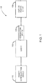
FIG. 1 depicts a block diagram of an apparatus for distributing power in accordance with an embodiment of the present disclosure; -
FIG. 2 depicts an exemplary apparatus for distributing power in accordance with an embodiment of the present disclosure; -
FIG. 3 depicts an exploded view of a power configuration device in accordance with an embodiment of the disclosure; -
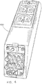
FIG. 4 depicts an exploded view of an outlet power strip in accordance with an embodiment of the present disclosure; -
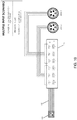
FIG. 5 depicts an exploded view of a connector device in accordance with an embodiment of the present disclosure; -
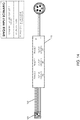
FIG. 6 depicts an exploded view of a connector device coupled with an outlet power strip in accordance with an embodiment of the present disclosure; -
FIG. 7 depicts a diagram of exemplary host box configurations and input power feeds in accordance with an embodiment of the present disclosure; -
FIG. 8 depicts various outlet power strips in accordance with embodiment of the present disclosure; -
FIGS. 9-16 depict exploded views of the various host box configurations that may be employed in a power configuration device in accordance with an embodiment of the present disclosure; and -
FIG. 17 depicts a power configuration device operable with a busway system in accordance with embodiment of the present disclosure. - Reference will now be made in detail to the subject matter disclosed, which is illustrated in the accompanying drawings.
- Referring to
FIG. 1 , a block diagram of anapparatus 100 for distributing power in accordance with an embodiment of the present disclosure is shown.Apparatus 100 may include apower configuration device 110 and anoutlet power strip 130.Apparatus 100 may further include acable 120, thecable 120 including aconnector device 125 configured to removably couple thepower configuration device 110 with theoutlet power strip 130. -
Power configuration device 110 is configured to couple with at least one input power feed and may include a host box configuration configured for a particular power characteristic. For example,power configuration device 110 may couple with a single or multiple input power feed. Input power feed may be a single phase or three phase alternating current (AC) input power and may vary in current, such as 16 Amperes to 50 Amperes. Input power feed(s) may include a plug or plugs to connect to the mains supply.Power configuration device 130 may include various host box configurations configured for a particular power characteristic. The particular power characteristic may include single phase power, three phase wye power, or three phase delta power received by thepower configuration device 110 and may include a particular current and a particular voltage. Various host box configurations may allow one or more input power feeds and may include zero or one or more circuit breakers. For example, various host box configurations may include zero, one, two or six circuit breakers. However, it is contemplated that the form factor of thepower configuration device 110 may remain a fixed size. This may allow replacement of power configuration devices without the need for adjustment or modification of the area surrounding thepower configuration device 110. -
Outlet power strip 110 may include a set of outlet power groups configured to supply a particular output power characteristic. The particular output characteristic may include a single phase supply at a particular voltage and a particular current, such as 230 Volts and 16-20 Amperes. Each outlet power group may include an electrical outlet and each outlet power strip may include a plurality of outlet power groups. It is further contemplated that each outlet power group may include different types of electrical outlets. For example, the electrical outlets may include C13 receptacles and C19 receptacles. It is contemplated that the wiring of theoutlet power strip 110 may allow it to universally connect and operate with various types of input supplies, including single phase, three phase wye and three phase delta power supplies. -
Cable 120 may include one or more conductors and may be held together with an overall sheath.Cable 120 may include aconnector device 125. In one embodiment,cable 120 may include twelve live conductors and two ground conductors. It is contemplated thatcable 120 andconnector device 125 may be the same for all the host box configurations depicted inFIGS. 9-16 .Connector device 125 is configured to allow connectivity to the twelve live conductors and two ground connectors.Power configuration device 110 oroutlet power strip 130 may include a corresponding connector device which may easily connect withconnector device 125 to allow easy connection and removal. It is contemplated thatconnector device 125 may include one or both of male and female connector parts while the corresponding connector device may include corresponding one or both of male and female connector parts. In an alternative embodiment,cable 120 may include a second connector device (not shown) and may connect topower configuration device 110 andoutlet power strip 130 via corresponding connector devices associated with each of thepower configuration device 110 oroutlet power strip 130. In an alternative embodiment,power configuration device 110 may be operatively coupled to theoutlet power strip 130 via a hardwired connection, removing the requirement of a cable with aconnection device 125. -
Power configuration device 110 may include a housing andoutlet power strip 130 may include a separate housing, distinct from the housing of the power configuration device.Cable 120 may couple thepower configuration device 110 andoutlet power strip 130. Becausepower configuration device 110 andoutlet power strip 130 may be separate, modular units and include separate housings, each can be removed and replaced without the requirement of replacing the other unit. This may provide a modular power system for computer and data storage equipment which may allow for efficient and cost-effective power distribution modifications. - Referring to
FIG. 2 , anexemplary apparatus 100 for distributing power in accordance with an embodiment of the present disclosure is shown.Power configuration device 110 may receive input power via aninput power feed 210.Power configuration device 110 may be coupled to anoutlet power strip 130 viacable 120 andconnector device 125.Outlet power strip 130 may include a corresponding connector device which is configured to mate and connect withconnector device 125. - Referring to
FIG. 3 , an exploded view of apower configuration device 110 in accordance with an embodiment of the disclosure is shown.Power configuration device 110 may be sized in a similar form factor to house all the various types of host box configurations in order to allow replacement of apower configuration device 110 in a particular area. It is contemplated that connections ofcables power configuration device 110 may be implemented throughconnector devices 125 whereby thepower configuration device 110 may further include corresponding connector devices. Additionally, power distribution units may include visual indicators and ports to describe information such as current usage and other power-related information. This information may be presented on a display of thepower configuration device 110. It is further contemplated that ports to allow network connectivity and communication with thepower configuration device 110 may be included. It is further contemplated that thepower configuration device 110 may include a wireless transceiver, such as WI-FI transceiver, to allow communication of power-related information associated with thepower configuration device 110 to provide remote monitoring. - Referring to
FIG. 4 , an exploded view of anoutlet power strip 130 in accordance with an embodiment of the present disclosure is shown.Outlet power strip 130 may include a plurality of electrical outlets, such as receptacles to provide power for electrical equipment.Outlet power strip 130 may be formed as a long, narrow device that may include a corresponding connector device at a top side of theoutlet power strip 130. In an embodiment, the placement of a corresponding connector device at a top side ofoutlet power strip 130 may allow easier connection withcable 120 andconnector device 125 which may come from above theoutlet power strip 130 in a rack or cabinet environment. Alternatively,outlet power strip 130 may include a hard-wired connection tocable 120 wherebycable 120 andconnector device 125 may easily connect withpower configuration device 110. It should be understood that theoutlet power strip 130 may be formed in a different form factor and location of the corresponding connector device may vary without departing from the scope and intent of the present disclosure. - Referring to
FIG. 5 , an exploded view of aconnector device 125 in accordance with an embodiment of the present disclosure is shown.Connector device 125 may be a universal connector and may support transfer of power from the various host box configurations ofpower configuration device 110 to theoutlet power strip 130. Referring toFIG. 6 , an exploded view of aconnector device 125 coupled with a corresponding connector device associated with anoutlet power strip 130 in accordance with an embodiment of the present disclosure is shown. It is contemplated thatconnector device 125 may include one or both of male and female connector parts while the corresponding connector device may include corresponding one or both of male and female connector parts. It should be understood that the views depicted inFIGS. 5 and6 may only represent embodiments and various types of connector assemblies may be employed without departing from the scope and intent of the present disclosure. - Referring to
FIG. 7 , a diagram of exemplary host box configurations and input power feeds in accordance with an embodiment of the present disclosure is shown. Diagram also shows exemplary total power available along with the power for each outlet group is shown. It is contemplated that the number of input power feeds may be one, two or three according to various embodiments of the present disclosure to provide single phase power, three phase wye power and three phase delta power. While these host box configurations are described, it is contemplated that additional host box configurations could be employed without departing from the scope and intent of the present disclosure. - Referring to
FIG. 8 , various outlet power strips in accordance with embodiment of the present disclosure are shown.Outlet power strip power configuration device 110. Advantageously, this may reduce the need to purchase breakers, cables and plugs when IT equipment is modified. Additionally, multiple power feeds may be combined to create higher density power in a cabinet while conserving space, preventing the need for four or six power distribution units. It is contemplated thatoutlet power strip - Referring to
FIGS. 9-16 , exploded views of the various host box configurations employed in thepower configuration device 110 in accordance with an embodiment of the present disclosure are shown. Advantageously, apower configuration device 110 may be swapped with apower configuration device 110 with a different host box configuration, such as a host box configuration depicted inFIGS. 9-16 . Adjustment of thepower configuration device 110 with one including a different host box configuration may allow efficient adjustment of the input power from one or more power feeds to theoutlet power strip 130. For example, if the output power was to remain the same, such as 2.93kW per outlet group but the number of feeds was changed from two input power feeds to three input power feeds, then thepower configuration device 110 as depicted inFIG. 10 could be changed with thepower configuration device 110 as depicted inFIG. 11 . Advantageously, this could occur without any change to theoutlet power strip 130, reducing waste and inefficiency. Additionally, the change in thepower configuration device 110 could be implemented without the need to modify theoutlet power strip 130, the structure supplying the power feeds, or the surrounding area as the form factor of thepower configuration device 110 will not have changed. - Additionally, referring once again to
FIG. 8 , anoutlet power strip 130A may be swapped with anotheroutlet power strip 130B if a different output is necessary, for example, a different type of outlet or numbers of different types of outlets. Advantageously, if an IT modification requires a different output power characteristic, such as a type of outlet, theoutlet power strip 130 may be swapped. This may be achieved without any change to thepower configuration device 110, thecable 120 orcable connector 125. Rather, a newoutlet power strip 130B, for example, may replace the oldoutlet power strip 130A, for example, and may be easily connected to thepower configuration device 110 via thecable 120 andcable connector 125. - Referring to
FIG. 17 , apower configuration device 110 operable with a busway system in accordance with embodiment of the present disclosure is shown.Busway 105 may be configured to support one or more power feeds. It is contemplated thatpower configuration device 110 may be operable as a busway tap device wherebypower configuration device 110 may connect to at least one power feed supported inbusway 105 and supply power viacable 120 andconnector device 125 to anoutlet power strip 130. It is contemplated thatpower configuration device 110 may include the host box configurations as shown inFIGS. 9-16 and may be removably connectable to thebusway 105. - It is contemplated that apparatus 100for distributing power may be implemented in a variety of alternative embodiments. For example, the exemplary host box configurations (referenced in
FIGS. 9-16 ) depict exemplary voltage, current and power values. In such a fashion, it can be understood the way in which apparatus for distributing power may be employed with a variety of host box configurations. However, it should be understood that the apparatus for distributing power is not limited to just the host box configurations depicted. Rather, other types of host box configurations may be employed, those that include other current, voltage and power values. For example, some of the host box configurations describe a 230 Volt input. It should be understood that there is a range of other voltages that could be employed, such as 110 volts or 240 volts. Other current values and corresponding power values may also be employed without departing from the scope and intent of the present disclosure. - It is believed that the present disclosure and many of its attendant advantages will be understood by the foregoing description, and it will be apparent that various changes may be made in the form, construction and arrangement of the components without departing from the disclosed subject matter or without sacrificing all of its material advantages. The form described is merely explanatory, and it is the intention of the following claims to encompass and include such changes.
Claims (7)
- An apparatus for distributing power, comprising:a power configuration device (110), the power configuration device configured to couple with at least one input power feed and including a host box configuration configured for a particular power characteristic;an outlet power strip (130), wherein the outlet power strip includes a set of outlet power groups configured to supply a particular output power characteristic; anda cable (120) including a connector device (125) configured to removably couple the power configuration device (110) with the outlet power strip (130), the cable including twelve live conductors and two ground conductors, wherein the connector device of the cable is configured to connect with a corresponding connector device associated with the outlet power strip.
- The apparatus of claim 1, wherein the host box configuration includes at least one of zero circuit breaker, one circuit breaker, two circuit breakers or six circuit breakers.
- The apparatus of claim 1, wherein the particular power characteristic includes at least one of single phase power, three phase wye power, or three phase delta power; and optionally, wherein the particular power characteristic includes a particular current and a particular voltage.
- The apparatus of claim 1, wherein the particular output power characteristic is a desired amount of power supplied to each group of the set of outlet power groups.
- The apparatus of claim 1, wherein the power configuration device (110) is either configured as a busway tap device, or, includes a housing and the outlet power strip (130) includes a second housing.
- The apparatus of claim 1, wherein an outlet power group includes at least one electrical outlet.
- The apparatus of claim 1 wherein the corresponding connector device (125) of the outlet power strip (130) is located on a top side of the outlet power strip (130).
Applications Claiming Priority (2)
| Application Number | Priority Date | Filing Date | Title |
|---|---|---|---|
| US201461989083P | 2014-05-06 | 2014-05-06 | |
| PCT/US2015/029522 WO2015171805A1 (en) | 2014-05-06 | 2015-05-06 | Apparatus for distributing power |
Publications (3)
| Publication Number | Publication Date |
|---|---|
| EP3140895A1 EP3140895A1 (en) | 2017-03-15 |
| EP3140895A4 EP3140895A4 (en) | 2017-12-20 |
| EP3140895B1 true EP3140895B1 (en) | 2019-07-10 |
Family
ID=54368625
Family Applications (1)
| Application Number | Title | Priority Date | Filing Date |
|---|---|---|---|
| EP15789985.7A Active EP3140895B1 (en) | 2014-05-06 | 2015-05-06 | Apparatus for distributing power |
Country Status (3)
| Country | Link |
|---|---|
| US (1) | US10154610B2 (en) |
| EP (1) | EP3140895B1 (en) |
| WO (1) | WO2015171805A1 (en) |
Families Citing this family (2)
| Publication number | Priority date | Publication date | Assignee | Title |
|---|---|---|---|---|
| CN113437552A (en) * | 2020-03-19 | 2021-09-24 | 阿里巴巴集团控股有限公司 | Power distribution unit and installation method thereof, cabinet and data center |
| US11973326B2 (en) * | 2020-12-22 | 2024-04-30 | Vertiv Corporation | Power distribution box |
Family Cites Families (20)
| Publication number | Priority date | Publication date | Assignee | Title |
|---|---|---|---|---|
| US5214314A (en) * | 1988-12-22 | 1993-05-25 | Siemens Energy & Automation, Inc. | Electrical distribution busway and bus plug arrangement |
| US7171461B2 (en) | 1996-07-23 | 2007-01-30 | Server Technology, Inc. | Network remote power management outlet strip |
| US6628009B1 (en) * | 2000-10-06 | 2003-09-30 | The Root Group, Inc. | Load balanced polyphase power distributing system |
| US6937461B1 (en) | 2001-11-28 | 2005-08-30 | Donahue, Iv William F. | Modular power distribution unit, module for the power distribution unit, and method of using the same |
| US6882530B2 (en) | 2003-03-31 | 2005-04-19 | Sun Microsystems, Inc. | Integrated component rack and AC power distribution |
| US7144264B2 (en) * | 2003-11-10 | 2006-12-05 | Pent Technologies, Inc. | Add-on electrical distribution assembly |
| US20070046103A1 (en) * | 2005-07-12 | 2007-03-01 | Belady Christian L | System for distributing AC power wthin an equipment rack |
| US7542268B2 (en) | 2006-03-17 | 2009-06-02 | Eaton Corporation | Modular electronic systems and methods using flexible power distribution unit interface |
| US7606014B2 (en) | 2006-06-16 | 2009-10-20 | American Power Conversion Corporation | Apparatus and method for scalable power distribution |
| US7619868B2 (en) | 2006-06-16 | 2009-11-17 | American Power Conversion Corporation | Apparatus and method for scalable power distribution |
| US20080093927A1 (en) | 2006-09-20 | 2008-04-24 | Server Technology, Inc. | Modular power distribution unit system |
| DE202006015827U1 (en) | 2006-10-16 | 2006-12-07 | Knürr AG | Power-bus bar system for casings and cupboards in information technology has a basic structure to conduct power and a module for distributing and supplying power |
| US7940504B2 (en) | 2007-06-21 | 2011-05-10 | American Power Conversion Corporation | Apparatus and method for scalable power distribution |
| US7697268B2 (en) | 2007-08-09 | 2010-04-13 | Haworth, Inc. | Modular electrical distribution system for a building |
| DE112009000697B4 (en) | 2008-03-19 | 2021-08-12 | Vertiv Corporation | Customizable power strip |
| US8039997B2 (en) | 2009-02-04 | 2011-10-18 | Thermocabinet, Llc | Power supply strip for electronic equipment |
| CA2861086C (en) | 2011-01-15 | 2018-02-20 | Gregory J. Marcinek | Power distribution unit |
| US8622756B2 (en) | 2011-05-18 | 2014-01-07 | Ole Falk Smed | Multi-function power strip |
| US8708736B2 (en) | 2012-02-01 | 2014-04-29 | Dell Products L.P. | Systems and methods for coupling AC power to a rack-level power infrastructure |
| US8902569B1 (en) * | 2012-07-27 | 2014-12-02 | Amazon Technologies, Inc. | Rack power distribution unit with detachable cables |
-
2015
- 2015-05-06 US US14/705,739 patent/US10154610B2/en active Active
- 2015-05-06 WO PCT/US2015/029522 patent/WO2015171805A1/en active Application Filing
- 2015-05-06 EP EP15789985.7A patent/EP3140895B1/en active Active
Non-Patent Citations (1)
| Title |
|---|
| None * |
Also Published As
| Publication number | Publication date |
|---|---|
| WO2015171805A1 (en) | 2015-11-12 |
| US10154610B2 (en) | 2018-12-11 |
| EP3140895A1 (en) | 2017-03-15 |
| EP3140895A4 (en) | 2017-12-20 |
| US20150325967A1 (en) | 2015-11-12 |
Similar Documents
| Publication | Publication Date | Title |
|---|---|---|
| US9733682B2 (en) | Scalable computing rack power distribution unit | |
| US10050803B2 (en) | Method for providing USB power over ethernet | |
| US20060146581A1 (en) | Power distribution device | |
| US6826036B2 (en) | Modular power distribution system for use in computer equipment racks | |
| US8500465B1 (en) | Adaptive cable connection system | |
| US7830043B1 (en) | Adaptable computer rack for power distribution | |
| EP3235103B1 (en) | Modular uninterruptible power supply and power distribution system | |
| US8039997B2 (en) | Power supply strip for electronic equipment | |
| US20140183977A1 (en) | Plug and Power Distribution and Control Apparatus | |
| US20140247537A1 (en) | Medium Voltage Power Distribution in Data Centers | |
| US20080309160A1 (en) | Modular blade enclosure power subsystem disign | |
| US9727100B1 (en) | Power distribution unit/power outlet unit for a distributed computing system | |
| EP3140895B1 (en) | Apparatus for distributing power | |
| US20130072070A1 (en) | Power distribution unit and power input module thereof | |
| US20130249286A1 (en) | Power supply device for server cabinets | |
| CN105870789A (en) | Data center busbar system | |
| CA2861086C (en) | Power distribution unit | |
| US20220200250A1 (en) | Power distribution box | |
| US20220385045A1 (en) | Blind-mated power distribution units | |
| US20150370297A1 (en) | Modular power distribution for computing systems | |
| US9972468B2 (en) | Information technology racks having integrated bus plugs and related systems and busways | |
| CN103324264A (en) | Power supply device of cabinet | |
| JP6202591B2 (en) | Power distribution equipment | |
| US20210313829A1 (en) | Power strip with integrated automatic transfer switch | |
| CN101800384B (en) | Power supply control distribution device especial for telecommunication |
Legal Events
| Date | Code | Title | Description |
|---|---|---|---|
| STAA | Information on the status of an ep patent application or granted ep patent |
Free format text: STATUS: THE INTERNATIONAL PUBLICATION HAS BEEN MADE |
|
| PUAI | Public reference made under article 153(3) epc to a published international application that has entered the european phase |
Free format text: ORIGINAL CODE: 0009012 |
|
| STAA | Information on the status of an ep patent application or granted ep patent |
Free format text: STATUS: REQUEST FOR EXAMINATION WAS MADE |
|
| 17P | Request for examination filed |
Effective date: 20161031 |
|
| AK | Designated contracting states |
Kind code of ref document: A1 Designated state(s): AL AT BE BG CH CY CZ DE DK EE ES FI FR GB GR HR HU IE IS IT LI LT LU LV MC MK MT NL NO PL PT RO RS SE SI SK SM TR |
|
| AX | Request for extension of the european patent |
Extension state: BA ME |
|
| DAV | Request for validation of the european patent (deleted) | ||
| DAX | Request for extension of the european patent (deleted) | ||
| A4 | Supplementary search report drawn up and despatched |
Effective date: 20171122 |
|
| RIC1 | Information provided on ipc code assigned before grant |
Ipc: G06F 1/26 20060101ALI20171116BHEP Ipc: H02J 3/12 20060101AFI20171116BHEP Ipc: H05K 7/14 20060101ALI20171116BHEP Ipc: H01R 25/00 20060101ALI20171116BHEP Ipc: H02J 9/00 20060101ALI20171116BHEP |
|
| RAP1 | Party data changed (applicant data changed or rights of an application transferred) |
Owner name: LIEBERT CORPORATION |
|
| RAP1 | Party data changed (applicant data changed or rights of an application transferred) |
Owner name: VERTIV CORPORATION |
|
| GRAP | Despatch of communication of intention to grant a patent |
Free format text: ORIGINAL CODE: EPIDOSNIGR1 |
|
| STAA | Information on the status of an ep patent application or granted ep patent |
Free format text: STATUS: GRANT OF PATENT IS INTENDED |
|
| INTG | Intention to grant announced |
Effective date: 20190107 |
|
| GRAS | Grant fee paid |
Free format text: ORIGINAL CODE: EPIDOSNIGR3 |
|
| GRAA | (expected) grant |
Free format text: ORIGINAL CODE: 0009210 |
|
| STAA | Information on the status of an ep patent application or granted ep patent |
Free format text: STATUS: THE PATENT HAS BEEN GRANTED |
|
| AK | Designated contracting states |
Kind code of ref document: B1 Designated state(s): AL AT BE BG CH CY CZ DE DK EE ES FI FR GB GR HR HU IE IS IT LI LT LU LV MC MK MT NL NO PL PT RO RS SE SI SK SM TR |
|
| REG | Reference to a national code |
Ref country code: GB Ref legal event code: FG4D |
|
| REG | Reference to a national code |
Ref country code: CH Ref legal event code: EP Ref country code: AT Ref legal event code: REF Ref document number: 1154525 Country of ref document: AT Kind code of ref document: T Effective date: 20190715 |
|
| REG | Reference to a national code |
Ref country code: DE Ref legal event code: R096 Ref document number: 602015033605 Country of ref document: DE |
|
| REG | Reference to a national code |
Ref country code: IE Ref legal event code: FG4D |
|
| REG | Reference to a national code |
Ref country code: NL Ref legal event code: FP |
|
| REG | Reference to a national code |
Ref country code: LT Ref legal event code: MG4D |
|
| REG | Reference to a national code |
Ref country code: AT Ref legal event code: MK05 Ref document number: 1154525 Country of ref document: AT Kind code of ref document: T Effective date: 20190710 |
|
| PG25 | Lapsed in a contracting state [announced via postgrant information from national office to epo] |
Ref country code: FI Free format text: LAPSE BECAUSE OF FAILURE TO SUBMIT A TRANSLATION OF THE DESCRIPTION OR TO PAY THE FEE WITHIN THE PRESCRIBED TIME-LIMIT Effective date: 20190710 Ref country code: AT Free format text: LAPSE BECAUSE OF FAILURE TO SUBMIT A TRANSLATION OF THE DESCRIPTION OR TO PAY THE FEE WITHIN THE PRESCRIBED TIME-LIMIT Effective date: 20190710 Ref country code: NO Free format text: LAPSE BECAUSE OF FAILURE TO SUBMIT A TRANSLATION OF THE DESCRIPTION OR TO PAY THE FEE WITHIN THE PRESCRIBED TIME-LIMIT Effective date: 20191010 Ref country code: SE Free format text: LAPSE BECAUSE OF FAILURE TO SUBMIT A TRANSLATION OF THE DESCRIPTION OR TO PAY THE FEE WITHIN THE PRESCRIBED TIME-LIMIT Effective date: 20190710 Ref country code: PT Free format text: LAPSE BECAUSE OF FAILURE TO SUBMIT A TRANSLATION OF THE DESCRIPTION OR TO PAY THE FEE WITHIN THE PRESCRIBED TIME-LIMIT Effective date: 20191111 Ref country code: BG Free format text: LAPSE BECAUSE OF FAILURE TO SUBMIT A TRANSLATION OF THE DESCRIPTION OR TO PAY THE FEE WITHIN THE PRESCRIBED TIME-LIMIT Effective date: 20191010 Ref country code: HR Free format text: LAPSE BECAUSE OF FAILURE TO SUBMIT A TRANSLATION OF THE DESCRIPTION OR TO PAY THE FEE WITHIN THE PRESCRIBED TIME-LIMIT Effective date: 20190710 Ref country code: LT Free format text: LAPSE BECAUSE OF FAILURE TO SUBMIT A TRANSLATION OF THE DESCRIPTION OR TO PAY THE FEE WITHIN THE PRESCRIBED TIME-LIMIT Effective date: 20190710 |
|
| PG25 | Lapsed in a contracting state [announced via postgrant information from national office to epo] |
Ref country code: RS Free format text: LAPSE BECAUSE OF FAILURE TO SUBMIT A TRANSLATION OF THE DESCRIPTION OR TO PAY THE FEE WITHIN THE PRESCRIBED TIME-LIMIT Effective date: 20190710 Ref country code: AL Free format text: LAPSE BECAUSE OF FAILURE TO SUBMIT A TRANSLATION OF THE DESCRIPTION OR TO PAY THE FEE WITHIN THE PRESCRIBED TIME-LIMIT Effective date: 20190710 Ref country code: GR Free format text: LAPSE BECAUSE OF FAILURE TO SUBMIT A TRANSLATION OF THE DESCRIPTION OR TO PAY THE FEE WITHIN THE PRESCRIBED TIME-LIMIT Effective date: 20191011 Ref country code: ES Free format text: LAPSE BECAUSE OF FAILURE TO SUBMIT A TRANSLATION OF THE DESCRIPTION OR TO PAY THE FEE WITHIN THE PRESCRIBED TIME-LIMIT Effective date: 20190710 Ref country code: LV Free format text: LAPSE BECAUSE OF FAILURE TO SUBMIT A TRANSLATION OF THE DESCRIPTION OR TO PAY THE FEE WITHIN THE PRESCRIBED TIME-LIMIT Effective date: 20190710 Ref country code: IS Free format text: LAPSE BECAUSE OF FAILURE TO SUBMIT A TRANSLATION OF THE DESCRIPTION OR TO PAY THE FEE WITHIN THE PRESCRIBED TIME-LIMIT Effective date: 20191110 |
|
| PG25 | Lapsed in a contracting state [announced via postgrant information from national office to epo] |
Ref country code: TR Free format text: LAPSE BECAUSE OF FAILURE TO SUBMIT A TRANSLATION OF THE DESCRIPTION OR TO PAY THE FEE WITHIN THE PRESCRIBED TIME-LIMIT Effective date: 20190710 |
|
| PG25 | Lapsed in a contracting state [announced via postgrant information from national office to epo] |
Ref country code: RO Free format text: LAPSE BECAUSE OF FAILURE TO SUBMIT A TRANSLATION OF THE DESCRIPTION OR TO PAY THE FEE WITHIN THE PRESCRIBED TIME-LIMIT Effective date: 20190710 Ref country code: EE Free format text: LAPSE BECAUSE OF FAILURE TO SUBMIT A TRANSLATION OF THE DESCRIPTION OR TO PAY THE FEE WITHIN THE PRESCRIBED TIME-LIMIT Effective date: 20190710 Ref country code: PL Free format text: LAPSE BECAUSE OF FAILURE TO SUBMIT A TRANSLATION OF THE DESCRIPTION OR TO PAY THE FEE WITHIN THE PRESCRIBED TIME-LIMIT Effective date: 20190710 Ref country code: DK Free format text: LAPSE BECAUSE OF FAILURE TO SUBMIT A TRANSLATION OF THE DESCRIPTION OR TO PAY THE FEE WITHIN THE PRESCRIBED TIME-LIMIT Effective date: 20190710 |
|
| PG25 | Lapsed in a contracting state [announced via postgrant information from national office to epo] |
Ref country code: SK Free format text: LAPSE BECAUSE OF FAILURE TO SUBMIT A TRANSLATION OF THE DESCRIPTION OR TO PAY THE FEE WITHIN THE PRESCRIBED TIME-LIMIT Effective date: 20190710 Ref country code: SM Free format text: LAPSE BECAUSE OF FAILURE TO SUBMIT A TRANSLATION OF THE DESCRIPTION OR TO PAY THE FEE WITHIN THE PRESCRIBED TIME-LIMIT Effective date: 20190710 Ref country code: CZ Free format text: LAPSE BECAUSE OF FAILURE TO SUBMIT A TRANSLATION OF THE DESCRIPTION OR TO PAY THE FEE WITHIN THE PRESCRIBED TIME-LIMIT Effective date: 20190710 Ref country code: IS Free format text: LAPSE BECAUSE OF FAILURE TO SUBMIT A TRANSLATION OF THE DESCRIPTION OR TO PAY THE FEE WITHIN THE PRESCRIBED TIME-LIMIT Effective date: 20200224 |
|
| REG | Reference to a national code |
Ref country code: DE Ref legal event code: R097 Ref document number: 602015033605 Country of ref document: DE |
|
| PLBE | No opposition filed within time limit |
Free format text: ORIGINAL CODE: 0009261 |
|
| STAA | Information on the status of an ep patent application or granted ep patent |
Free format text: STATUS: NO OPPOSITION FILED WITHIN TIME LIMIT |
|
| PG2D | Information on lapse in contracting state deleted |
Ref country code: IS |
|
| 26N | No opposition filed |
Effective date: 20200603 |
|
| PG25 | Lapsed in a contracting state [announced via postgrant information from national office to epo] |
Ref country code: SI Free format text: LAPSE BECAUSE OF FAILURE TO SUBMIT A TRANSLATION OF THE DESCRIPTION OR TO PAY THE FEE WITHIN THE PRESCRIBED TIME-LIMIT Effective date: 20190710 |
|
| PG25 | Lapsed in a contracting state [announced via postgrant information from national office to epo] |
Ref country code: LI Free format text: LAPSE BECAUSE OF NON-PAYMENT OF DUE FEES Effective date: 20200531 Ref country code: MC Free format text: LAPSE BECAUSE OF FAILURE TO SUBMIT A TRANSLATION OF THE DESCRIPTION OR TO PAY THE FEE WITHIN THE PRESCRIBED TIME-LIMIT Effective date: 20190710 Ref country code: CH Free format text: LAPSE BECAUSE OF NON-PAYMENT OF DUE FEES Effective date: 20200531 |
|
| REG | Reference to a national code |
Ref country code: BE Ref legal event code: MM Effective date: 20200531 |
|
| PG25 | Lapsed in a contracting state [announced via postgrant information from national office to epo] |
Ref country code: LU Free format text: LAPSE BECAUSE OF NON-PAYMENT OF DUE FEES Effective date: 20200506 |
|
| PG25 | Lapsed in a contracting state [announced via postgrant information from national office to epo] |
Ref country code: BE Free format text: LAPSE BECAUSE OF NON-PAYMENT OF DUE FEES Effective date: 20200531 |
|
| PG25 | Lapsed in a contracting state [announced via postgrant information from national office to epo] |
Ref country code: MT Free format text: LAPSE BECAUSE OF FAILURE TO SUBMIT A TRANSLATION OF THE DESCRIPTION OR TO PAY THE FEE WITHIN THE PRESCRIBED TIME-LIMIT Effective date: 20190710 Ref country code: CY Free format text: LAPSE BECAUSE OF FAILURE TO SUBMIT A TRANSLATION OF THE DESCRIPTION OR TO PAY THE FEE WITHIN THE PRESCRIBED TIME-LIMIT Effective date: 20190710 |
|
| PG25 | Lapsed in a contracting state [announced via postgrant information from national office to epo] |
Ref country code: MK Free format text: LAPSE BECAUSE OF FAILURE TO SUBMIT A TRANSLATION OF THE DESCRIPTION OR TO PAY THE FEE WITHIN THE PRESCRIBED TIME-LIMIT Effective date: 20190710 |
|
| P01 | Opt-out of the competence of the unified patent court (upc) registered |
Effective date: 20230621 |
|
| PGFP | Annual fee paid to national office [announced via postgrant information from national office to epo] |
Ref country code: NL Payment date: 20230526 Year of fee payment: 9 Ref country code: IT Payment date: 20230519 Year of fee payment: 9 Ref country code: IE Payment date: 20230529 Year of fee payment: 9 Ref country code: FR Payment date: 20230525 Year of fee payment: 9 Ref country code: DE Payment date: 20230530 Year of fee payment: 9 |
|
| PGFP | Annual fee paid to national office [announced via postgrant information from national office to epo] |
Ref country code: GB Payment date: 20230529 Year of fee payment: 9 |