EP3139195B1 - Remote target identification using laser doppler vibrometry - Google Patents
Remote target identification using laser doppler vibrometry Download PDFInfo
- Publication number
- EP3139195B1 EP3139195B1 EP16186868.2A EP16186868A EP3139195B1 EP 3139195 B1 EP3139195 B1 EP 3139195B1 EP 16186868 A EP16186868 A EP 16186868A EP 3139195 B1 EP3139195 B1 EP 3139195B1
- Authority
- EP
- European Patent Office
- Prior art keywords
- interferometer
- optical circulator
- telescope
- target
- laser device
- Prior art date
- Legal status (The legal status is an assumption and is not a legal conclusion. Google has not performed a legal analysis and makes no representation as to the accuracy of the status listed.)
- Active
Links
- 230000003287 optical effect Effects 0.000 claims description 34
- 238000000034 method Methods 0.000 claims description 16
- 238000001514 detection method Methods 0.000 claims description 15
- 230000000694 effects Effects 0.000 claims 2
- 238000012544 monitoring process Methods 0.000 claims 2
- 230000005540 biological transmission Effects 0.000 description 9
- 230000003595 spectral effect Effects 0.000 description 6
- 230000033001 locomotion Effects 0.000 description 5
- 238000012360 testing method Methods 0.000 description 4
- 230000008859 change Effects 0.000 description 3
- 238000010586 diagram Methods 0.000 description 3
- 238000005259 measurement Methods 0.000 description 3
- 239000013307 optical fiber Substances 0.000 description 3
- 230000001427 coherent effect Effects 0.000 description 2
- 238000011161 development Methods 0.000 description 2
- 239000000835 fiber Substances 0.000 description 2
- 238000000926 separation method Methods 0.000 description 2
- 230000003044 adaptive effect Effects 0.000 description 1
- 230000002238 attenuated effect Effects 0.000 description 1
- 230000035559 beat frequency Effects 0.000 description 1
- 230000008901 benefit Effects 0.000 description 1
- 230000008878 coupling Effects 0.000 description 1
- 238000010168 coupling process Methods 0.000 description 1
- 238000005859 coupling reaction Methods 0.000 description 1
- 230000001066 destructive effect Effects 0.000 description 1
- 238000006073 displacement reaction Methods 0.000 description 1
- 238000005516 engineering process Methods 0.000 description 1
- 230000005284 excitation Effects 0.000 description 1
- 231100001261 hazardous Toxicity 0.000 description 1
- 238000004599 local-density approximation Methods 0.000 description 1
- 238000012986 modification Methods 0.000 description 1
- 230000004048 modification Effects 0.000 description 1
- 230000002085 persistent effect Effects 0.000 description 1
- 238000012545 processing Methods 0.000 description 1
- 238000003672 processing method Methods 0.000 description 1
- 230000005855 radiation Effects 0.000 description 1
- 230000009467 reduction Effects 0.000 description 1
- 230000004044 response Effects 0.000 description 1
- 239000004065 semiconductor Substances 0.000 description 1
- 238000004611 spectroscopical analysis Methods 0.000 description 1
- 238000000411 transmission spectrum Methods 0.000 description 1
Images


Classifications
-
- G—PHYSICS
- G01—MEASURING; TESTING
- G01H—MEASUREMENT OF MECHANICAL VIBRATIONS OR ULTRASONIC, SONIC OR INFRASONIC WAVES
- G01H9/00—Measuring mechanical vibrations or ultrasonic, sonic or infrasonic waves by using radiation-sensitive means, e.g. optical means
-
- G—PHYSICS
- G01—MEASURING; TESTING
- G01H—MEASUREMENT OF MECHANICAL VIBRATIONS OR ULTRASONIC, SONIC OR INFRASONIC WAVES
- G01H13/00—Measuring resonant frequency
-
- G—PHYSICS
- G01—MEASURING; TESTING
- G01P—MEASURING LINEAR OR ANGULAR SPEED, ACCELERATION, DECELERATION, OR SHOCK; INDICATING PRESENCE, ABSENCE, OR DIRECTION, OF MOVEMENT
- G01P3/00—Measuring linear or angular speed; Measuring differences of linear or angular speeds
- G01P3/36—Devices characterised by the use of optical means, e.g. using infrared, visible, or ultraviolet light
-
- G—PHYSICS
- G01—MEASURING; TESTING
- G01S—RADIO DIRECTION-FINDING; RADIO NAVIGATION; DETERMINING DISTANCE OR VELOCITY BY USE OF RADIO WAVES; LOCATING OR PRESENCE-DETECTING BY USE OF THE REFLECTION OR RERADIATION OF RADIO WAVES; ANALOGOUS ARRANGEMENTS USING OTHER WAVES
- G01S17/00—Systems using the reflection or reradiation of electromagnetic waves other than radio waves, e.g. lidar systems
- G01S17/02—Systems using the reflection of electromagnetic waves other than radio waves
- G01S17/50—Systems of measurement based on relative movement of target
- G01S17/58—Velocity or trajectory determination systems; Sense-of-movement determination systems
-
- G—PHYSICS
- G01—MEASURING; TESTING
- G01S—RADIO DIRECTION-FINDING; RADIO NAVIGATION; DETERMINING DISTANCE OR VELOCITY BY USE OF RADIO WAVES; LOCATING OR PRESENCE-DETECTING BY USE OF THE REFLECTION OR RERADIATION OF RADIO WAVES; ANALOGOUS ARRANGEMENTS USING OTHER WAVES
- G01S7/00—Details of systems according to groups G01S13/00, G01S15/00, G01S17/00
- G01S7/48—Details of systems according to groups G01S13/00, G01S15/00, G01S17/00 of systems according to group G01S17/00
- G01S7/4802—Details of systems according to groups G01S13/00, G01S15/00, G01S17/00 of systems according to group G01S17/00 using analysis of echo signal for target characterisation; Target signature; Target cross-section
-
- G—PHYSICS
- G01—MEASURING; TESTING
- G01S—RADIO DIRECTION-FINDING; RADIO NAVIGATION; DETERMINING DISTANCE OR VELOCITY BY USE OF RADIO WAVES; LOCATING OR PRESENCE-DETECTING BY USE OF THE REFLECTION OR RERADIATION OF RADIO WAVES; ANALOGOUS ARRANGEMENTS USING OTHER WAVES
- G01S7/00—Details of systems according to groups G01S13/00, G01S15/00, G01S17/00
- G01S7/48—Details of systems according to groups G01S13/00, G01S15/00, G01S17/00 of systems according to group G01S17/00
- G01S7/481—Constructional features, e.g. arrangements of optical elements
- G01S7/4811—Constructional features, e.g. arrangements of optical elements common to transmitter and receiver
- G01S7/4812—Constructional features, e.g. arrangements of optical elements common to transmitter and receiver transmitted and received beams following a coaxial path
Definitions
- This disclosure generally relates to systems and methods for identifying a moving target at a remote location.
- this disclosure relates to measuring vibrations of a moving target for the purpose of target identification.
- radar devices To track a moving target, radar devices typically detect the motion of the target based upon Doppler information provided by the radar signals that are reflected off the moving target.
- the movement of the target in a radial direction, relative to the radar device causes the radar signals that reflect off the moving target to return to the radar device with a frequency that is different than the frequency that was transmitted by the radar device.
- the radial movement of the target changes the frequency of the radar signal an amount that is proportional to the relative velocity of the target such that the change in frequency of the radar signal may be used to determine the location and speed of the moving target and to accordingly track the moving target.
- a laser Doppler vibrometer can be used to make noncontact vibration measurements of a surface.
- the laser beam from the LDV is directed at the surface of interest, and the vibration amplitude and frequency are extracted from the laser light reflected from the surface by detecting the Doppler shift due to the motion of that surface.
- the output of an LDV is generally a continuous analog voltage that is directly proportional to the target velocity component along the direction of the laser beam.
- a typical vibrometer comprises a two-beam laser interferometer that measures the frequency (or phase) difference between an internal reference beam and a test beam.
- the test beam is directed at the target, and scattered light from the target is collected and interfered with the reference beam on a photodetector, typically a photodiode.
- a photodetector typically a photodiode.
- Most commercial vibrometers work in a heterodyne regime by adding a known frequency shift (typically 30-40 MHz) to one of the beams. This frequency shift is usually generated by a Bragg cell, or an acousto-optic modulator.
- the beam from the laser which has a frequency f o , is divided into a reference beam and a test beam using a beamsplitter.
- the test beam then passes through the Bragg cell, which adds a frequency shift f b .
- This frequency shifted beam is then directed toward the target.
- the initial frequency of the laser is very high (>10 14 Hz), which is higher than the response of the detector.
- the detector does respond, however, to the beat frequency between the two beams, which is at f b + f d (typically in the tens of MHz range).
- the output of the photodetector is a standard frequency-modulated signal, with the Bragg cell frequency as the carrier frequency, and the Doppler shift as the modulation frequency. This signal can be demodulated to derive the velocity versus time of the vibrating target.
- the LDV described in the previous paragraph has at least the following limitations:
- the subject matter disclosed in detail below is directed to an LDV architecture and detection technique that can remotely identify targets based on their natural vibration frequencies using a scanning (i.e., tunable) Fabry-Perot interferometer.
- the proposed systems and methods can have stand-off distances longer than the coherence length of the laser by using spectroscopic detection methods instead of coherent heterodyne detection using a local oscillator. Pulsed lasers can be used which have high power output.
- the speed of the detectable target is not limited. Also the mixing efficiency of the return signal can be improved.
- the systems and methods disclosed herein can be used in surveillance of remote targets.
- the surveillance can be from ground-based, airborne, or space-based platforms.
- the system could be directed at military, industrial (including hazardous environments), urban, commercial, and other targets of opportunity.
- FIG. 1 is a block diagram identifying some components of and showing an architecture of a laser Doppler vibrometer in accordance with one embodiment.
- the system depicted in FIG. 1 comprises: a laser device 2; an optical circulator 6 having a Port P1 optically coupled to the laser device 2 by means of an optical coupler 4; a telescope 8 optically coupled to a Port P2 of the optical circulator 6; a scanning (i.e., tunable) Fabry-Perot interferometer 12 optically coupled to a Port P3 of the optical circulator 6; a photodetector 14 (e.g., a photodiode) optically coupled to the Fabry-Perot interferometer 12; and a signal processor 16 electrically coupled to the photodetector 14.
- a laser device 2 an optical circulator 6 having a Port P1 optically coupled to the laser device 2 by means of an optical coupler 4
- a telescope 8 optically coupled to a Port P2 of the optical circulator 6
- the telescope can be used to direct laser light toward a target 10 and then recapture returning laser light reflected or scattered by target 10. That recaptured laser light enters Port P2 and then exits Port P3 of the optical circulator 6.
- the laser light exiting Port P3 of the optical circulator 6 enters the Fabry-Perot interferometer 12.
- some of the laser light emitted by the laser source 2 is directed by the optical circulator 6 to the Fabry-Perot interferometer 12.
- the Fabry-Perot interferometer 12 typically comprises an optically transparent medium (e.g., air or optical fiber) in a cavity 22 partly defined by two parallel highly reflecting mirrors 14 and 16.
- a length of single-mode optical fiber, placed in the cavity 22 may extend between the mirrors 14 and 16.
- the mirrors 14 and 16 are configured so that some incident light is reflected and some incident light is transmitted.
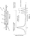
- the arrow A in FIG. 2 represents laser light from the optical circulator 6 (see FIG. 1 ) which is impinging on the mirror 14 (the portion of that incident light which is reflected by mirror 14 is not indicated in FIG. 2 ).
- the double-headed arrow B in FIG. 2 represents internally reflected laser light inside the cavity 22.
- the arrow C in FIG. 2 represents laser light transmitted by the Fabry-Perot interferometer 12 to the photodetector 14.
- the transmission spectrum of the Fabry-Perot interferometer 12 as a function of wavelength exhibits peaks of large transmission corresponding to resonances of the interferometer.
- the transmission function of the Fabry-Pérot interferometer 12 is caused by interference between the multiple reflections of light between the two reflecting mirrors 12 and 14. Constructive interference occurs if the transmitted beams are in phase, and this corresponds to a high-transmission peak of the interferometer. If the transmitted beams are out-of-phase, destructive interference occurs and this corresponds to a transmission minimum. Maximum transmission occurs when the optical path length difference between each transmitted beam is an integer multiple of the wavelength. The wavelength separation between adjacent transmission peaks is called the free spectral range of the interferometer.
- the Fabry-Pérot interferometer 12 passes wavelengths that are equal to integer fractions of the cavity length; all other wavelengths are attenuated.
- the Fabry-Perot interferometer 12 further comprises a plurality of piezoelectric transducers 18, which can be employed to change the length of the cavity 22 between mirrors 14 and 16, and thereby tune the wavelength of the Fabry-Pérot interferometer 12 so that it acts as a filter.
- the lengths of the piezoelectric transducers 18 are typically changed by application of a positive variable voltage to the piezoelectric transducers 18.
- the distance between the mirrors 14 and 16 can be tuned in order to change the wavelengths which will be passed by the scanning Fabry-Perot interferometer 12.
- the scanning Fabry-Pérot interferometer 12 is controlled to have a pass band which corresponds to the wavelengths that are used in the measurement. More specifically, the distance between the mirrors 14 and 16 is controlled by the signal processor 16, which supplies varying scanning voltages to the piezoelectric transducers 18 via a voltage supply line 20. In this manner the Fabry-Perot interferometer 12 is controlled to scan its pass band through a required wavelength range, such as the wavelength range depicted in FIG. 3 ,
- FIG. 3 is a graph showing the detection voltages (vertical axis) produced by the photodetector 14 in dependence on the intensity of laser light passed through the Fabry-Pérot interferometer 12 as the scanning voltage (horizontal axis) is varied.
- the laser light leaked to the Fabry-Pérot interferometer 12 from the laser source 2 by the optical circulator 6 produces a transmission peak centered at scanning voltage V 1 .
- This transmission peak at scanning voltage V 1 is treated as the reference signal by the signal processor 16.
- the rest of the laser light from laser source 2 is passed by the optical circulator 6 to the telescope 8, which directs the resulting laser beam toward the target 10.
- the laser light returned to the telescope 8 from the target 10 is then passed via the optical circulator 6 to the Fabry-Pérot interferometer 12, which scans the incoming laser light as the cavity length is being changed.
- the resulting output from the Fabry-Pérot interferometer 12 causes the photodetector 14 to produce transmission peaks at scanning voltages V 2 , V 3 , and V 4 .
- the difference between the scanning voltages V 1 and V 3 is a measure of the Doppler shift produced by the velocity component of the center of mass of the target 10 along the line of sight of the telescope 8, whereas the transmission peaks (indicated by dashed lines in FIG. 3 ) centered at scanning voltages V 2 and V 4 are caused by surface vibrations of the target 10.
- the scanning speed is controlled by the signal processor 16 in such a way that during the scan, a predetermined total amount of transmitted light is received after the Fabry-Pérot interferometer 12 at each wavelength of radiation.
- FIG. 4 is a flowchart identifying steps of a method for identifying a remote target using a tunable interferometer in accordance with one embodiment.
- the operation of the laser Doppler vibrometer starts with a monochromatic, low noise, high spectral purity laser.
- the laser light emitted by laser source 2 is directed toward and propagates into Port P1 of the optical circulator (step 24). Some of the laser light entering the optical circulator via Port P1 exits Port P2 and is sent to the telescope 8; other laser light is leaked via Port P3 to the Fabry-Pérot interferometer 12 (step 26).
- the propagation could be in optical fiber or air/vacuum.
- the leakage light from Port P1 to Port P3 is used as the reference signal by the signal processor 16.
- Light exiting Port P2 is coupled into the telescope and propagates to the target (step 28). Laser light reflecting from the target is Doppler shifted and re-captured by the telescope (step 30). The recaptured laser light enters Port P2 and exits through Port P3 of the optical circulator 6 and is sent to the Fabry-Pérot interferometer 12 (step 32).
- the Fabry-Pérot interferometer 12 is tuned by applying a voltage (scanning voltage) to the piezoelectric transducers (step 34).
- the scanning voltage changes the length of the piezoelectric transducers, hence changing the distance between the two mirrors 14 and 16 inside the Fabry-Perot interferometer 12.
- the distance between the two mirrors determines the wavelength of light that gets through.
- Any laser light that is not filtered out by the Fabry-Pérot interferometer 12 is detected by the photodetector 14 (e.g., a photodiode), which converts the light intensity into a voltage (detection voltage) (step 36).
- the photodetector 14 e.g., a photodiode
- the signal processor 16 monitors the detection voltage as a function of the scanning voltage (step 38). It identifies the scanning voltages where the peak detection voltages occur (step 40). The differences in scanning voltages where the peaks occur are then compared to a calibration table to determine the relative speed of the target as well as the resonant vibration frequency of the target (step 42). Based on the detected resonant frequency the target can be identified (step 44).
- FIG. 5 is a graph showing the laser Doppler shift (in MHz) as a function of the surface vibration frequency (Hz) and the associated surface speed (m/s). Assuming for the sake of illustration that the system detects a surface vibration on a target having a vibration frequency of 1 kHz and a peak displacement of 1 mm, the resulting peak surface speed will be 1 m/s, as indicated by the vertical dashed line in FIG. 5 . A surface speed of 1 m/s would produce a Doppler shift of approximately 1 MHz, as indicated by the horizontal dashed line in FIG. 5 . A properly designed scanning Fabry-Pérot interferometer can easily detect this 1-MHz shift.
- the system disclosed above can be used at distances of tens or hundreds of kilometers to identify and differentiate targets based on their natural vibration frequencies. Recent advances in laser power output and spectral purity could enable new applications.
- a commercially available fiber laser at 1.55- ⁇ m, 10-W continuous wave output, and spectral width ⁇ 1 kHz provides a coherence length of at least 100 km.
- Using the laser radar equation (10-cm aperture) one can calculate that a 50-km distance separation (100-km round trip) would result in a shot noise limited signal-to-noise ratio (SNR) of ⁇ 300X or 25 dB. This is better than the 20-dB SNR typically required for standard optical signal processing methods.
- One proposed application of this technology is to detect decoy warheads on intercontinental ballistic missiles (ICBM).
- ICBM intercontinental ballistic missiles
- the detection modality assumption is that the actual warheads have different masses from the decoy ones, hence different natural vibration frequencies.
- the excitation energy comes from the rocket engines or aerodynamic forces coupling during reentry.
- the biggest challenge is that at Mach 10, a 50-km standoff gives the defender only 15 seconds to track, identify, and target.
- Another proposed application is to use laser Doppler vibrometry for persistent surveillance from ground-based, airborne, or space-based platforms.
- the system could be directed at military and industrial targets of opportunities. For example, the vibration frequency of a missile silo lid could be monitored to determine if it is occupied.
- spectroscopic detection techniques such as Fabry-Pérot and laser comb spectroscopy are required. Atmospheric turbulence could be corrected using adaptive optics, or alternatively considered as part of the random noise floor in the signal processing of long duration data.
Landscapes
- Physics & Mathematics (AREA)
- Engineering & Computer Science (AREA)
- General Physics & Mathematics (AREA)
- Computer Networks & Wireless Communication (AREA)
- Radar, Positioning & Navigation (AREA)
- Remote Sensing (AREA)
- Electromagnetism (AREA)
- Power Engineering (AREA)
- Measurement Of Mechanical Vibrations Or Ultrasonic Waves (AREA)
- Optical Radar Systems And Details Thereof (AREA)
Description
- This disclosure generally relates to systems and methods for identifying a moving target at a remote location. In particular, this disclosure relates to measuring vibrations of a moving target for the purpose of target identification.
- To track a moving target, radar devices typically detect the motion of the target based upon Doppler information provided by the radar signals that are reflected off the moving target. The movement of the target in a radial direction, relative to the radar device, causes the radar signals that reflect off the moving target to return to the radar device with a frequency that is different than the frequency that was transmitted by the radar device. Specifically, the radial movement of the target changes the frequency of the radar signal an amount that is proportional to the relative velocity of the target such that the change in frequency of the radar signal may be used to determine the location and speed of the moving target and to accordingly track the moving target.
- A laser Doppler vibrometer (LDV) can be used to make noncontact vibration measurements of a surface. The laser beam from the LDV is directed at the surface of interest, and the vibration amplitude and frequency are extracted from the laser light reflected from the surface by detecting the Doppler shift due to the motion of that surface. The output of an LDV is generally a continuous analog voltage that is directly proportional to the target velocity component along the direction of the laser beam.
- A typical vibrometer comprises a two-beam laser interferometer that measures the frequency (or phase) difference between an internal reference beam and a test beam. The test beam is directed at the target, and scattered light from the target is collected and interfered with the reference beam on a photodetector, typically a photodiode. Most commercial vibrometers work in a heterodyne regime by adding a known frequency shift (typically 30-40 MHz) to one of the beams. This frequency shift is usually generated by a Bragg cell, or an acousto-optic modulator. In vibrometers of this type, the beam from the laser, which has a frequency fo, is divided into a reference beam and a test beam using a beamsplitter. The test beam then passes through the Bragg cell, which adds a frequency shift fb. This frequency shifted beam is then directed toward the target. The motion of the target adds a Doppler shift to the beam given by fd = 2*v(t)*cos(α)/A, where v(t) is the velocity of the target as a function of time, α is the angle between the laser beam and the velocity vector, and λ is the wavelength of the light. Light scatters from the target in all directions, but some portion of the light is collected by the LDV and reflected by the beamsplitter to the photodetector. This light has a frequency equal to fo + fb + fd. This scattered light is combined with the reference beam at the photodetector. The initial frequency of the laser is very high (>1014 Hz), which is higher than the response of the detector. The detector does respond, however, to the beat frequency between the two beams, which is at fb + fd (typically in the tens of MHz range). The output of the photodetector is a standard frequency-modulated signal, with the Bragg cell frequency as the carrier frequency, and the Doppler shift as the modulation frequency. This signal can be demodulated to derive the velocity versus time of the vibrating target.
- The LDV described in the previous paragraph has at least the following limitations:
- (1) The acousto-optic modulator Bragg cell has a maximum modulation frequency of ~400 MHz, whereas a Mach 10 target has a Doppler shift of 4.4 GHz.
- (2) The detection range is limited by the laser coherence length. Coherent heterodyne detection requires stand-off distances at less than half the laser coherence length.
- (3) Mixing efficiency is low due to the complex optical train, namely beam splitters, which allow only part of the return signal to participate in the intermediate frequency mixing.
- It would be desirable to provide an LDV for target identification which does not have the foregoing limitations.
- Rodrigo, Peter John et al: 'Influence of laser frequency noise on scanning Fabry-Perot interferometer based laser Doppler velocimetry", Optomechatronic micro/nano devices and components II: 8-10 October 2007, Proceedings of SPIE, vol. 8992, 8 March 2014 discloses a study of the performance of a scanning Fabry-Perot interferometer based laser Doppler velocimeter (sFPI-LDV) and comparison of two candidate 1.5 um singlefrequency laser sources for the system - a fiber laser (FL) and a semiconductor laser (SL).
- The subject matter disclosed in detail below is directed to an LDV architecture and detection technique that can remotely identify targets based on their natural vibration frequencies using a scanning (i.e., tunable) Fabry-Perot interferometer. The proposed systems and methods can have stand-off distances longer than the coherence length of the laser by using spectroscopic detection methods instead of coherent heterodyne detection using a local oscillator. Pulsed lasers can be used which have high power output. In addition, by not using an acousto-optic modulator, the speed of the detectable target is not limited. Also the mixing efficiency of the return signal can be improved.
- The invention is set out in the appended set of claims.
- The systems and methods disclosed herein can be used in surveillance of remote targets. The surveillance can be from ground-based, airborne, or space-based platforms. The system could be directed at military, industrial (including hazardous environments), urban, commercial, and other targets of opportunity.
- Other aspects of systems and methods which use laser Doppler vibrometry to identify remote targets based on their natural vibration frequencies are disclosed below.
-
-
FIG. 1 is a block diagram identifying some components of and showing an architecture of a laser Doppler vibrometer in accordance with one embodiment. -
FIG. 2 is a diagram representing a conceptual view of a scanning Fabry-Perot interferometer in accordance with one embodiment. -
FIG. 3 is a graph showing the scanning voltage produced by the photodetector in dependence on the intensity of light passed through the scanning Fabry-Perot interferometer depicted inFIG. 1 . -
FIG. 4 is a flowchart identifying steps of a method for identifying a remote target using a tunable interferometer in accordance with one embodiment. -
FIG. 5 is a graph showing the laser Doppler shift (in MHz) as a function of the surface vibration frequency (Hz) and the associated surface speed (m/s). - Reference will hereinafter be made to the drawings in which similar elements in different drawings bear the same reference numerals.
- Illustrative embodiments of a laser Doppler vibrometer suitable for tracking and identifying a remote target will be described in some detail below. However, not all features of an actual implementation are described in this specification. A person skilled in the art will appreciate that in the development of any such actual embodiment, numerous implementationspecific decisions must be made to achieve the developer's specific goals, such as compliance with system-related and business-related constraints, which will vary from one implementation to another. Moreover, it will be appreciated that such a development effort might be complex and timeconsuming, but would nevertheless be a routine undertaking for those of ordinary skill in the art having the benefit of this disclosure.
-
FIG. 1 is a block diagram identifying some components of and showing an architecture of a laser Doppler vibrometer in accordance with one embodiment. The system depicted inFIG. 1 comprises: alaser device 2; anoptical circulator 6 having a Port P1 optically coupled to thelaser device 2 by means of anoptical coupler 4; a telescope 8 optically coupled to a Port P2 of theoptical circulator 6; a scanning (i.e., tunable) Fabry-Perot interferometer 12 optically coupled to a Port P3 of theoptical circulator 6; a photodetector 14 (e.g., a photodiode) optically coupled to the Fabry-Perot interferometer 12; and asignal processor 16 electrically coupled to thephotodetector 14. The telescope can be used to direct laser light toward atarget 10 and then recapture returning laser light reflected or scattered bytarget 10. That recaptured laser light enters Port P2 and then exits Port P3 of theoptical circulator 6. The laser light exiting Port P3 of theoptical circulator 6 enters the Fabry-Perot interferometer 12. In addition, some of the laser light emitted by thelaser source 2 is directed by theoptical circulator 6 to the Fabry-Perot interferometer 12. - As depicted in
FIG. 2 , the Fabry-Perot interferometer 12 typically comprises an optically transparent medium (e.g., air or optical fiber) in acavity 22 partly defined by two parallel highly reflectingmirrors cavity 22, may extend between themirrors mirrors FIG. 2 represents laser light from the optical circulator 6 (seeFIG. 1 ) which is impinging on the mirror 14 (the portion of that incident light which is reflected bymirror 14 is not indicated inFIG. 2 ). The double-headed arrow B inFIG. 2 represents internally reflected laser light inside thecavity 22. The arrow C inFIG. 2 represents laser light transmitted by the Fabry-Perot interferometer 12 to thephotodetector 14. - The transmission spectrum of the Fabry-
Perot interferometer 12 as a function of wavelength exhibits peaks of large transmission corresponding to resonances of the interferometer. The transmission function of the Fabry-Pérot interferometer 12 is caused by interference between the multiple reflections of light between the two reflectingmirrors Pérot interferometer 12 passes wavelengths that are equal to integer fractions of the cavity length; all other wavelengths are attenuated. - Still referring to
FIG. 2 , the Fabry-Perot interferometer 12 further comprises a plurality ofpiezoelectric transducers 18, which can be employed to change the length of thecavity 22 betweenmirrors Pérot interferometer 12 so that it acts as a filter. The lengths of thepiezoelectric transducers 18 are typically changed by application of a positive variable voltage to thepiezoelectric transducers 18. Thus the distance between themirrors Perot interferometer 12. - In the embodiment depicted in
FIG. 1 , the scanning Fabry-Pérot interferometer 12 is controlled to have a pass band which corresponds to the wavelengths that are used in the measurement. More specifically, the distance between themirrors signal processor 16, which supplies varying scanning voltages to thepiezoelectric transducers 18 via avoltage supply line 20. In this manner the Fabry-Perot interferometer 12 is controlled to scan its pass band through a required wavelength range, such as the wavelength range depicted inFIG. 3 , -
FIG. 3 is a graph showing the detection voltages (vertical axis) produced by thephotodetector 14 in dependence on the intensity of laser light passed through the Fabry-Pérot interferometer 12 as the scanning voltage (horizontal axis) is varied. In the example, depicted inFIG. 3 , the laser light leaked to the Fabry-Pérot interferometer 12 from thelaser source 2 by theoptical circulator 6 produces a transmission peak centered at scanning voltage V1. This transmission peak at scanning voltage V1 is treated as the reference signal by thesignal processor 16. The rest of the laser light fromlaser source 2 is passed by theoptical circulator 6 to the telescope 8, which directs the resulting laser beam toward thetarget 10. The laser light returned to the telescope 8 from thetarget 10 is then passed via theoptical circulator 6 to the Fabry-Pérot interferometer 12, which scans the incoming laser light as the cavity length is being changed. In the example depicted inFIG. 3 , the resulting output from the Fabry-Pérot interferometer 12 causes thephotodetector 14 to produce transmission peaks at scanning voltages V2, V3, and V4. The difference between the scanning voltages V1 and V3 is a measure of the Doppler shift produced by the velocity component of the center of mass of thetarget 10 along the line of sight of the telescope 8, whereas the transmission peaks (indicated by dashed lines inFIG. 3 ) centered at scanning voltages V2 and V4 are caused by surface vibrations of thetarget 10. - The scanning speed is controlled by the
signal processor 16 in such a way that during the scan, a predetermined total amount of transmitted light is received after the Fabry-Pérot interferometer 12 at each wavelength of radiation. By programming suitable scanning rate functions, it is possible to provide target specific spectral measurements for several properties of the target. -
FIG. 4 is a flowchart identifying steps of a method for identifying a remote target using a tunable interferometer in accordance with one embodiment. The operation of the laser Doppler vibrometer starts with a monochromatic, low noise, high spectral purity laser. The laser light emitted bylaser source 2 is directed toward and propagates into Port P1 of the optical circulator (step 24). Some of the laser light entering the optical circulator via Port P1 exits Port P2 and is sent to the telescope 8; other laser light is leaked via Port P3 to the Fabry-Pérot interferometer 12 (step 26). The propagation could be in optical fiber or air/vacuum. The leakage light from Port P1 to Port P3 is used as the reference signal by thesignal processor 16. Light exiting Port P2 is coupled into the telescope and propagates to the target (step 28). Laser light reflecting from the target is Doppler shifted and re-captured by the telescope (step 30). The recaptured laser light enters Port P2 and exits through Port P3 of theoptical circulator 6 and is sent to the Fabry-Pérot interferometer 12 (step 32). - The Fabry-
Pérot interferometer 12 is tuned by applying a voltage (scanning voltage) to the piezoelectric transducers (step 34). The scanning voltage changes the length of the piezoelectric transducers, hence changing the distance between the twomirrors Perot interferometer 12. The distance between the two mirrors determines the wavelength of light that gets through. Any laser light that is not filtered out by the Fabry-Pérot interferometer 12 is detected by the photodetector 14 (e.g., a photodiode), which converts the light intensity into a voltage (detection voltage) (step 36). - The
signal processor 16 monitors the detection voltage as a function of the scanning voltage (step 38). It identifies the scanning voltages where the peak detection voltages occur (step 40). The differences in scanning voltages where the peaks occur are then compared to a calibration table to determine the relative speed of the target as well as the resonant vibration frequency of the target (step 42). Based on the detected resonant frequency the target can be identified (step 44). -
FIG. 5 is a graph showing the laser Doppler shift (in MHz) as a function of the surface vibration frequency (Hz) and the associated surface speed (m/s). Assuming for the sake of illustration that the system detects a surface vibration on a target having a vibration frequency of 1 kHz and a peak displacement of 1 mm, the resulting peak surface speed will be 1 m/s, as indicated by the vertical dashed line inFIG. 5 . A surface speed of 1 m/s would produce a Doppler shift of approximately 1 MHz, as indicated by the horizontal dashed line inFIG. 5 . A properly designed scanning Fabry-Pérot interferometer can easily detect this 1-MHz shift. - The system disclosed above can be used at distances of tens or hundreds of kilometers to identify and differentiate targets based on their natural vibration frequencies. Recent advances in laser power output and spectral purity could enable new applications. For example, a commercially available fiber laser at 1.55-µm, 10-W continuous wave output, and spectral width <1 kHz provides a coherence length of at least 100 km. Using the laser radar equation (10-cm aperture), one can calculate that a 50-km distance separation (100-km round trip) would result in a shot noise limited signal-to-noise ratio (SNR) of ~300X or 25 dB. This is better than the 20-dB SNR typically required for standard optical signal processing methods. Lasers with <1-Hz spectral widths exist.
- One proposed application of this technology is to detect decoy warheads on intercontinental ballistic missiles (ICBM). The detection modality assumption is that the actual warheads have different masses from the decoy ones, hence different natural vibration frequencies. The excitation energy comes from the rocket engines or aerodynamic forces coupling during reentry. The biggest challenge is that at
Mach 10, a 50-km standoff gives the defender only 15 seconds to track, identify, and target. - Another proposed application is to use laser Doppler vibrometry for persistent surveillance from ground-based, airborne, or space-based platforms. The system could be directed at military and industrial targets of opportunities. For example, the vibration frequency of a missile silo lid could be monitored to determine if it is occupied. For distances larger than the coherence length, spectroscopic detection techniques such as Fabry-Pérot and laser comb spectroscopy are required. Atmospheric turbulence could be corrected using adaptive optics, or alternatively considered as part of the random noise floor in the signal processing of long duration data.
- While systems and methods that use laser Doppler vibrometers to track and identify remote targets have been described with reference to various embodiments, it will be understood by those skilled in the art that various changes may be made and equivalents may be substituted for elements thereof without departing from the teachings herein. In addition, many modifications may be made to adapt the concepts and reductions to practice disclosed herein to a particular situation. Accordingly, it is intended that the subject matter covered by the claims not be limited to the disclosed embodiments.
- The method claims set forth hereinafter should not be construed to require that the steps recited therein be performed in alphabetical order or in the order in which they are recited. Nor should they be construed to exclude any portions of two or more steps being performed concurrently or alternatingly.
Claims (15)
- A system comprising:a laser device (2);an optical circulator (6) optically coupled to said laser device;a telescope (8) optically coupled to said optical circulator;a tunable interferometer (12) optically coupled to said optical circulator;a photodetector (14) optically coupled to said tunable interferometer; anda signal processor (16) electrically coupled to said photodetector, wherein said tunable interferometer is a scanning Fabry-Perot interferometer comprising a plurality of piezoelectric transducers (18), and said signal processor is electrically coupled to said piezoelectric transducers, and wherein said signal processor is configured to supply scanning voltages to said piezoelectric transducers which have the effect of adjusting a wavelength of said tunable interferometer so that the wavelength varies within a range of wavelengths that includes a wavelength of light emitted by said laser device and a wavelength of light which was first emitted by said laser device and then Doppler shifted by a target (10),wherein said signal processor (16) is configured to perform the following operations:(a) monitoring (38) a detection voltage produced by said photodetector (14) as a function of the scanning voltages supplied to said piezoelectric transducers (18);(b) identifying (40) scanning voltages where peak detection voltages occur;(c) comparing (42) differences in scanning voltages where the peaks occur to reference voltages in a calibration table to determine the relative speed of the target (10) as well as the resonant vibration frequency of the target; and(d) identifying (44) the target based on the resonant vibration frequency determined in operation (c).
- The system as recited in claim 1, wherein said tunable interferometer (12) is configured to detect Doppler shifts within a range that includes 1 MHz.
- The system as recited in any of claims 1-2, wherein said optical circulator (6) is configured to pass a first portion of light emitted by said laser device (2) to said telescope (8) and a second portion of light emitted by said laser device to said tunable interferometer (12).
- The system as recited in any of claims 1-3, wherein said optical circulator (6) is configured to pass light from said telescope (8) to said tunable interferometer (12).
- The system as recited in any of claims 1-4, comprising a ground-based platform that supports at least said laser device (2), said optical circulator (6), said telescope (8), said tunable interferometer (12), and said photodetector (14).
- The system as recited in any of claims 1-4, comprising an airborne platform that supports at least said laser device (2), said optical circulator (6), said telescope (8), said tunable interferometer (12), and said photodetector (14).
- The system as recited in any of claims 1-4, comprising a space-based platform that supports at least said laser device (2), said optical circulator (6), said telescope (8), said tunable interferometer (12), and said photodetector (14).
- A method comprising:directing (24) laser light into an optical circulator (6);sending (26) respective portions of said laser light to a telescope (8) and to an interferometer (12);directing (28) the laser light received from the optical circulator by the telescope toward a target (10);recapturing (30) laser light reflected from the target using the telescope;sending (32) recaptured laser light from the telescope to the interferometer via the optical circulator;supplying (34) scanning voltages to piezoelectric transducers (18) of the interferometer; andphotodetecting (36) recaptured laser light that passes through the interferometer,wherein said interferometer is a scanning Fabry-Perot interferometer comprising said piezoelectric transducers, and a signal processor (16) is electrically coupled to said piezoelectric transducers, andwherein said signal processor supplies the scanning voltages to said piezoelectric transducers which have the effect of adjusting a wavelength of said interferometer so that the wavelength varies within a range of wavelengths that includes a wavelength of said laser light emitted by a laser device (2) and a wavelength of light which was first emitted by said laser device and then Doppler shifted by the target,wherein said signal processor (16) performs the following operations:(a) monitoring (38) a detection voltage as a function of the scanning voltages supplied to said piezoelectric transducers (18);(b) identifying (40) scanning voltages where peak detection voltages occur;(c) comparing (42) differences in scanning voltages where the peaks occur to reference voltages in a calibration table to determine the relative speed of the target (10) as well as the resonant vibration frequency of the target; and(d) identifying (44) the target based on the resonant vibration frequency determined in operation (c).
- The method as recited in claim 8, wherein said interferometer (12) detects Doppler shifts within a range that includes 1 MHz.
- The method as recited in any of claims 8-9, wherein said optical circulator (6) passes a first portion of said laser light emitted by said laser device (2) to said telescope (8).
- The method as recited in any of claims 8-10, wherein said optical circulator (6) passes a second portion of said laser light emitted by said laser device (2) to said interferometer (12).
- The method as recited in any of claims 8-11, wherein said optical circulator (6) passes said recaptured laser light from said telescope (8) to said interferometer (12).
- The method as recited in any of claims 8-12, wherein a ground-based platform supports at least said laser device (2), said optical circulator (6), said telescope (8), said interferometer (12), and a photodetector (14).
- The method as recited in any of claims 8-12, wherein an airborne platform supports at least said laser device (2), said optical circulator (6), said telescope (8), said interferometer (12), and a photodetector (14).
- The method as recited in any of claims 8-12, wherein a space-based platform supports at least said laser device (2), said optical circulator (6), said telescope (8), said interferometer (12), and a photodetector (14).
Applications Claiming Priority (1)
| Application Number | Priority Date | Filing Date | Title |
|---|---|---|---|
| US14/843,685 US10156473B2 (en) | 2015-09-02 | 2015-09-02 | Remote target identification using laser Doppler vibrometry |
Publications (2)
| Publication Number | Publication Date |
|---|---|
| EP3139195A1 EP3139195A1 (en) | 2017-03-08 |
| EP3139195B1 true EP3139195B1 (en) | 2022-04-13 |
Family
ID=56852207
Family Applications (1)
| Application Number | Title | Priority Date | Filing Date |
|---|---|---|---|
| EP16186868.2A Active EP3139195B1 (en) | 2015-09-02 | 2016-09-01 | Remote target identification using laser doppler vibrometry |
Country Status (3)
| Country | Link |
|---|---|
| US (1) | US10156473B2 (en) |
| EP (1) | EP3139195B1 (en) |
| JP (1) | JP6674353B2 (en) |
Families Citing this family (13)
| Publication number | Priority date | Publication date | Assignee | Title |
|---|---|---|---|---|
| CN108139270B (en) * | 2015-10-02 | 2021-06-08 | 浜松光子学株式会社 | Optical detection device |
| CN107479046B (en) * | 2017-07-06 | 2019-09-06 | 北京空间机电研究所 | A kind of spaceborne tunable multichannel Fabry-Perot frequency discriminator block |
| US11650294B2 (en) * | 2018-03-28 | 2023-05-16 | Murata Manufacturing Co., Ltd. | Fabry-pérot element in lidar device |
| US11400544B2 (en) | 2018-06-08 | 2022-08-02 | Hewlett-Packard Development Company, L.P. | Selective laser melting (SLM) additive manufacturing |
| CN109374914A (en) * | 2018-09-18 | 2019-02-22 | 西安工业大学 | Larger Dynamic measurement range all -fiber Doppler speed measuring device |
| CN112867912B (en) | 2018-10-22 | 2024-01-23 | Drs网络和成像系统公司 | Integrated optical quantum weak measurement amplification sensor for remote sensing |
| CN110108349B (en) * | 2019-05-23 | 2022-04-22 | 中国科学院光电研究院 | Laser vibration meter |
| CN110440899B (en) * | 2019-08-09 | 2024-02-06 | 大连理工大学 | Common-path dual-wavelength quadrature phase demodulation system |
| CN113138012A (en) * | 2020-01-17 | 2021-07-20 | 中国海洋大学 | Laser radar remote measurement detection method for vibration of wind driven generator |
| CN111721968B (en) * | 2020-06-03 | 2022-06-28 | 华东师范大学 | Method for measuring gas flow velocity based on double-optical comb system |
| WO2022093815A1 (en) | 2020-10-27 | 2022-05-05 | Drs Network & Imaging Systems, Llc | Optical gyroscope with weak measurement amplification readout |
| CN114838803B (en) * | 2022-04-29 | 2023-11-10 | 北京杏林睿光科技有限公司 | Vibration measuring device and vibration measuring method |
| CN115979263B (en) * | 2023-03-21 | 2023-06-02 | 中国人民解放军国防科技大学 | Navigation method and system for low-altitude flight carrier |
Family Cites Families (16)
| Publication number | Priority date | Publication date | Assignee | Title |
|---|---|---|---|---|
| US3968362A (en) | 1975-08-11 | 1976-07-06 | Honeywell Inc. | Optical system for laser doppler homodyne detection |
| US5192979A (en) | 1984-09-26 | 1993-03-09 | Siemens Aktiengesellschaft | Method and apparatus for recognizing and identifying targets |
| JPH049687A (en) * | 1990-04-27 | 1992-01-14 | Nippon Steel Corp | Laser doppler speedmeter |
| US5434668A (en) | 1992-04-01 | 1995-07-18 | Electronics & Space Corp. | Laser vibrometer identification friend-or-foe (IFF) system |
| CN1089443C (en) * | 1998-04-24 | 2002-08-21 | 中国科学院上海光学精密机械研究所 | Incoherent laser radar system atmospheric sounding |
| JP3513432B2 (en) * | 1999-07-27 | 2004-03-31 | 三菱重工業株式会社 | Optical frequency domain reflection measuring device and optical frequency domain reflection measuring method |
| US6657732B2 (en) | 2001-05-04 | 2003-12-02 | Hrl Laboratories, Llc | Vibrometer system using a two input beam phase conjugate mirror |
| US6728645B1 (en) | 2003-01-07 | 2004-04-27 | Electro-Optics Research & Development Ltd. | Method and system for automatic identification of objects type according to their characteristic spectrum of vibration frequencies |
| US7477398B2 (en) | 2003-03-31 | 2009-01-13 | Metrolaser, Inc. | Multi-beam heterodyne laser doppler vibrometer |
| EP1879015B1 (en) | 2005-03-02 | 2018-08-01 | Japan Science and Technology Agency | Heterodyne laser doppler probe and measurement system using the same |
| US7554670B2 (en) | 2006-01-18 | 2009-06-30 | Seagate Technology Llc | Surface inspection by double pass laser doppler vibrometry |
| EP2201342A2 (en) | 2007-10-03 | 2010-06-30 | Dublin Institute of Technology | A multipoint laser doppler vibrometer |
| JP2012184967A (en) * | 2011-03-03 | 2012-09-27 | Canon Inc | Wavelength scanning interferometer |
| CN103344947A (en) | 2013-06-04 | 2013-10-09 | 四川大学 | Micro-motion target characteristic extraction method based on micro-Doppler effect |
| CN103499820B (en) | 2013-09-27 | 2015-09-09 | 中国科学技术大学 | A kind of closed loop control method of all-fiber direct detection Doppler lidar for wind measurement |
| CN103605124B (en) | 2013-11-05 | 2015-11-25 | 中国科学技术大学 | A kind of quickly calibrated system and method for Direct-detection Doppler lidar |
-
2015
- 2015-09-02 US US14/843,685 patent/US10156473B2/en active Active
-
2016
- 2016-08-23 JP JP2016162739A patent/JP6674353B2/en active Active
- 2016-09-01 EP EP16186868.2A patent/EP3139195B1/en active Active
Also Published As
| Publication number | Publication date |
|---|---|
| US20170059392A1 (en) | 2017-03-02 |
| US10156473B2 (en) | 2018-12-18 |
| JP6674353B2 (en) | 2020-04-01 |
| JP2017049243A (en) | 2017-03-09 |
| EP3139195A1 (en) | 2017-03-08 |
Similar Documents
| Publication | Publication Date | Title |
|---|---|---|
| EP3139195B1 (en) | Remote target identification using laser doppler vibrometry | |
| US9702975B2 (en) | Lidar measuring system and lidar measuring method | |
| US10598769B2 (en) | Coaxial direct-detection LIDAR-system | |
| CA2800267C (en) | Method and apparatus for a pulsed coherent laser range finder | |
| US6388739B1 (en) | Self-referencing microdoppler ladar receiver and associated detection method | |
| US11531111B2 (en) | 360 degrees field of view scanning lidar with no movable parts | |
| CA3141211C (en) | Frequency modulated scanning lidar with 360 degrees field of view | |
| EP3218741B1 (en) | System and method for measuring doppler effect utilizing elastic and inelastic light scattering | |
| US11906665B2 (en) | Method for scanning a transmitted beam through a 360° field-of-view (FOV) | |
| JP7329995B2 (en) | LASER DOPPLER RADAR DEVICE AND WIND SPEED CALCULATION METHOD | |
| Renhorn et al. | Coherent laser radar for vibrometry: robust design and adaptive signal processing | |
| US11768291B1 (en) | High dynamic range ranging interferometer | |
| Onori et al. | A dual-frequency coherent noise lidar for robust range-Doppler measurements | |
| Sturm et al. | A technique for removing platform vibration noise from a pulsed ladar vibration sensor | |
| IL286820A (en) | Method and system for mapping and range detection |
Legal Events
| Date | Code | Title | Description |
|---|---|---|---|
| PUAI | Public reference made under article 153(3) epc to a published international application that has entered the european phase |
Free format text: ORIGINAL CODE: 0009012 |
|
| STAA | Information on the status of an ep patent application or granted ep patent |
Free format text: STATUS: REQUEST FOR EXAMINATION WAS MADE |
|
| 17P | Request for examination filed |
Effective date: 20160901 |
|
| AK | Designated contracting states |
Kind code of ref document: A1 Designated state(s): AL AT BE BG CH CY CZ DE DK EE ES FI FR GB GR HR HU IE IS IT LI LT LU LV MC MK MT NL NO PL PT RO RS SE SI SK SM TR |
|
| AX | Request for extension of the european patent |
Extension state: BA ME |
|
| STAA | Information on the status of an ep patent application or granted ep patent |
Free format text: STATUS: EXAMINATION IS IN PROGRESS |
|
| 17Q | First examination report despatched |
Effective date: 20200130 |
|
| STAA | Information on the status of an ep patent application or granted ep patent |
Free format text: STATUS: EXAMINATION IS IN PROGRESS |
|
| REG | Reference to a national code |
Ref country code: DE Ref legal event code: R079 Ref document number: 602016071001 Country of ref document: DE Free format text: PREVIOUS MAIN CLASS: G01S0007481000 Ipc: G01S0017580000 |
|
| GRAP | Despatch of communication of intention to grant a patent |
Free format text: ORIGINAL CODE: EPIDOSNIGR1 |
|
| STAA | Information on the status of an ep patent application or granted ep patent |
Free format text: STATUS: GRANT OF PATENT IS INTENDED |
|
| GRAJ | Information related to disapproval of communication of intention to grant by the applicant or resumption of examination proceedings by the epo deleted |
Free format text: ORIGINAL CODE: EPIDOSDIGR1 |
|
| GRAP | Despatch of communication of intention to grant a patent |
Free format text: ORIGINAL CODE: EPIDOSNIGR1 |
|
| RIC1 | Information provided on ipc code assigned before grant |
Ipc: G01H 9/00 20060101ALI20210927BHEP Ipc: G01H 13/00 20060101ALI20210927BHEP Ipc: G01S 7/48 20060101ALI20210927BHEP Ipc: G01S 7/481 20060101ALI20210927BHEP Ipc: G01S 17/58 20060101AFI20210927BHEP |
|
| STAA | Information on the status of an ep patent application or granted ep patent |
Free format text: STATUS: GRANT OF PATENT IS INTENDED |
|
| INTG | Intention to grant announced |
Effective date: 20211013 |
|
| INTG | Intention to grant announced |
Effective date: 20211104 |
|
| GRAS | Grant fee paid |
Free format text: ORIGINAL CODE: EPIDOSNIGR3 |
|
| GRAA | (expected) grant |
Free format text: ORIGINAL CODE: 0009210 |
|
| STAA | Information on the status of an ep patent application or granted ep patent |
Free format text: STATUS: THE PATENT HAS BEEN GRANTED |
|
| AK | Designated contracting states |
Kind code of ref document: B1 Designated state(s): AL AT BE BG CH CY CZ DE DK EE ES FI FR GB GR HR HU IE IS IT LI LT LU LV MC MK MT NL NO PL PT RO RS SE SI SK SM TR |
|
| REG | Reference to a national code |
Ref country code: GB Ref legal event code: FG4D |
|
| REG | Reference to a national code |
Ref country code: CH Ref legal event code: EP |
|
| REG | Reference to a national code |
Ref country code: DE Ref legal event code: R096 Ref document number: 602016071001 Country of ref document: DE |
|
| REG | Reference to a national code |
Ref country code: IE Ref legal event code: FG4D |
|
| REG | Reference to a national code |
Ref country code: AT Ref legal event code: REF Ref document number: 1483817 Country of ref document: AT Kind code of ref document: T Effective date: 20220515 |
|
| REG | Reference to a national code |
Ref country code: LT Ref legal event code: MG9D |
|
| REG | Reference to a national code |
Ref country code: NL Ref legal event code: MP Effective date: 20220413 |
|
| REG | Reference to a national code |
Ref country code: AT Ref legal event code: MK05 Ref document number: 1483817 Country of ref document: AT Kind code of ref document: T Effective date: 20220413 |
|
| PG25 | Lapsed in a contracting state [announced via postgrant information from national office to epo] |
Ref country code: NL Free format text: LAPSE BECAUSE OF FAILURE TO SUBMIT A TRANSLATION OF THE DESCRIPTION OR TO PAY THE FEE WITHIN THE PRESCRIBED TIME-LIMIT Effective date: 20220413 |
|
| PG25 | Lapsed in a contracting state [announced via postgrant information from national office to epo] |
Ref country code: SE Free format text: LAPSE BECAUSE OF FAILURE TO SUBMIT A TRANSLATION OF THE DESCRIPTION OR TO PAY THE FEE WITHIN THE PRESCRIBED TIME-LIMIT Effective date: 20220413 Ref country code: PT Free format text: LAPSE BECAUSE OF FAILURE TO SUBMIT A TRANSLATION OF THE DESCRIPTION OR TO PAY THE FEE WITHIN THE PRESCRIBED TIME-LIMIT Effective date: 20220816 Ref country code: NO Free format text: LAPSE BECAUSE OF FAILURE TO SUBMIT A TRANSLATION OF THE DESCRIPTION OR TO PAY THE FEE WITHIN THE PRESCRIBED TIME-LIMIT Effective date: 20220713 Ref country code: LT Free format text: LAPSE BECAUSE OF FAILURE TO SUBMIT A TRANSLATION OF THE DESCRIPTION OR TO PAY THE FEE WITHIN THE PRESCRIBED TIME-LIMIT Effective date: 20220413 Ref country code: HR Free format text: LAPSE BECAUSE OF FAILURE TO SUBMIT A TRANSLATION OF THE DESCRIPTION OR TO PAY THE FEE WITHIN THE PRESCRIBED TIME-LIMIT Effective date: 20220413 Ref country code: GR Free format text: LAPSE BECAUSE OF FAILURE TO SUBMIT A TRANSLATION OF THE DESCRIPTION OR TO PAY THE FEE WITHIN THE PRESCRIBED TIME-LIMIT Effective date: 20220714 Ref country code: FI Free format text: LAPSE BECAUSE OF FAILURE TO SUBMIT A TRANSLATION OF THE DESCRIPTION OR TO PAY THE FEE WITHIN THE PRESCRIBED TIME-LIMIT Effective date: 20220413 Ref country code: ES Free format text: LAPSE BECAUSE OF FAILURE TO SUBMIT A TRANSLATION OF THE DESCRIPTION OR TO PAY THE FEE WITHIN THE PRESCRIBED TIME-LIMIT Effective date: 20220413 Ref country code: BG Free format text: LAPSE BECAUSE OF FAILURE TO SUBMIT A TRANSLATION OF THE DESCRIPTION OR TO PAY THE FEE WITHIN THE PRESCRIBED TIME-LIMIT Effective date: 20220713 Ref country code: AT Free format text: LAPSE BECAUSE OF FAILURE TO SUBMIT A TRANSLATION OF THE DESCRIPTION OR TO PAY THE FEE WITHIN THE PRESCRIBED TIME-LIMIT Effective date: 20220413 |
|
| PG25 | Lapsed in a contracting state [announced via postgrant information from national office to epo] |
Ref country code: RS Free format text: LAPSE BECAUSE OF FAILURE TO SUBMIT A TRANSLATION OF THE DESCRIPTION OR TO PAY THE FEE WITHIN THE PRESCRIBED TIME-LIMIT Effective date: 20220413 Ref country code: PL Free format text: LAPSE BECAUSE OF FAILURE TO SUBMIT A TRANSLATION OF THE DESCRIPTION OR TO PAY THE FEE WITHIN THE PRESCRIBED TIME-LIMIT Effective date: 20220413 Ref country code: LV Free format text: LAPSE BECAUSE OF FAILURE TO SUBMIT A TRANSLATION OF THE DESCRIPTION OR TO PAY THE FEE WITHIN THE PRESCRIBED TIME-LIMIT Effective date: 20220413 Ref country code: IS Free format text: LAPSE BECAUSE OF FAILURE TO SUBMIT A TRANSLATION OF THE DESCRIPTION OR TO PAY THE FEE WITHIN THE PRESCRIBED TIME-LIMIT Effective date: 20220813 |
|
| REG | Reference to a national code |
Ref country code: DE Ref legal event code: R097 Ref document number: 602016071001 Country of ref document: DE |
|
| PG25 | Lapsed in a contracting state [announced via postgrant information from national office to epo] |
Ref country code: SM Free format text: LAPSE BECAUSE OF FAILURE TO SUBMIT A TRANSLATION OF THE DESCRIPTION OR TO PAY THE FEE WITHIN THE PRESCRIBED TIME-LIMIT Effective date: 20220413 Ref country code: SK Free format text: LAPSE BECAUSE OF FAILURE TO SUBMIT A TRANSLATION OF THE DESCRIPTION OR TO PAY THE FEE WITHIN THE PRESCRIBED TIME-LIMIT Effective date: 20220413 Ref country code: RO Free format text: LAPSE BECAUSE OF FAILURE TO SUBMIT A TRANSLATION OF THE DESCRIPTION OR TO PAY THE FEE WITHIN THE PRESCRIBED TIME-LIMIT Effective date: 20220413 Ref country code: EE Free format text: LAPSE BECAUSE OF FAILURE TO SUBMIT A TRANSLATION OF THE DESCRIPTION OR TO PAY THE FEE WITHIN THE PRESCRIBED TIME-LIMIT Effective date: 20220413 Ref country code: DK Free format text: LAPSE BECAUSE OF FAILURE TO SUBMIT A TRANSLATION OF THE DESCRIPTION OR TO PAY THE FEE WITHIN THE PRESCRIBED TIME-LIMIT Effective date: 20220413 Ref country code: CZ Free format text: LAPSE BECAUSE OF FAILURE TO SUBMIT A TRANSLATION OF THE DESCRIPTION OR TO PAY THE FEE WITHIN THE PRESCRIBED TIME-LIMIT Effective date: 20220413 |
|
| PLBE | No opposition filed within time limit |
Free format text: ORIGINAL CODE: 0009261 |
|
| STAA | Information on the status of an ep patent application or granted ep patent |
Free format text: STATUS: NO OPPOSITION FILED WITHIN TIME LIMIT |
|
| 26N | No opposition filed |
Effective date: 20230116 |
|
| PG25 | Lapsed in a contracting state [announced via postgrant information from national office to epo] |
Ref country code: AL Free format text: LAPSE BECAUSE OF FAILURE TO SUBMIT A TRANSLATION OF THE DESCRIPTION OR TO PAY THE FEE WITHIN THE PRESCRIBED TIME-LIMIT Effective date: 20220413 |
|
| PG25 | Lapsed in a contracting state [announced via postgrant information from national office to epo] |
Ref country code: MC Free format text: LAPSE BECAUSE OF FAILURE TO SUBMIT A TRANSLATION OF THE DESCRIPTION OR TO PAY THE FEE WITHIN THE PRESCRIBED TIME-LIMIT Effective date: 20220413 |
|
| REG | Reference to a national code |
Ref country code: CH Ref legal event code: PL |
|
| REG | Reference to a national code |
Ref country code: BE Ref legal event code: MM Effective date: 20220930 |
|
| PG25 | Lapsed in a contracting state [announced via postgrant information from national office to epo] |
Ref country code: SI Free format text: LAPSE BECAUSE OF FAILURE TO SUBMIT A TRANSLATION OF THE DESCRIPTION OR TO PAY THE FEE WITHIN THE PRESCRIBED TIME-LIMIT Effective date: 20220413 |
|
| P01 | Opt-out of the competence of the unified patent court (upc) registered |
Effective date: 20230516 |
|
| PG25 | Lapsed in a contracting state [announced via postgrant information from national office to epo] |
Ref country code: LU Free format text: LAPSE BECAUSE OF NON-PAYMENT OF DUE FEES Effective date: 20220901 |
|
| PG25 | Lapsed in a contracting state [announced via postgrant information from national office to epo] |
Ref country code: LI Free format text: LAPSE BECAUSE OF NON-PAYMENT OF DUE FEES Effective date: 20220930 Ref country code: IE Free format text: LAPSE BECAUSE OF NON-PAYMENT OF DUE FEES Effective date: 20220901 Ref country code: CH Free format text: LAPSE BECAUSE OF NON-PAYMENT OF DUE FEES Effective date: 20220930 |
|
| PG25 | Lapsed in a contracting state [announced via postgrant information from national office to epo] |
Ref country code: BE Free format text: LAPSE BECAUSE OF NON-PAYMENT OF DUE FEES Effective date: 20220930 |
|
| PGFP | Annual fee paid to national office [announced via postgrant information from national office to epo] |
Ref country code: GB Payment date: 20230927 Year of fee payment: 8 |
|
| PGFP | Annual fee paid to national office [announced via postgrant information from national office to epo] |
Ref country code: FR Payment date: 20230925 Year of fee payment: 8 Ref country code: DE Payment date: 20230927 Year of fee payment: 8 |
|
| PG25 | Lapsed in a contracting state [announced via postgrant information from national office to epo] |
Ref country code: IT Free format text: LAPSE BECAUSE OF FAILURE TO SUBMIT A TRANSLATION OF THE DESCRIPTION OR TO PAY THE FEE WITHIN THE PRESCRIBED TIME-LIMIT Effective date: 20220413 |
|
| PG25 | Lapsed in a contracting state [announced via postgrant information from national office to epo] |
Ref country code: HU Free format text: LAPSE BECAUSE OF FAILURE TO SUBMIT A TRANSLATION OF THE DESCRIPTION OR TO PAY THE FEE WITHIN THE PRESCRIBED TIME-LIMIT; INVALID AB INITIO Effective date: 20160901 |
|
| PG25 | Lapsed in a contracting state [announced via postgrant information from national office to epo] |
Ref country code: CY Free format text: LAPSE BECAUSE OF FAILURE TO SUBMIT A TRANSLATION OF THE DESCRIPTION OR TO PAY THE FEE WITHIN THE PRESCRIBED TIME-LIMIT Effective date: 20220413 |