EP3137735B1 - Distributed acoustic sensing using low pulse repetition rates - Google Patents
Distributed acoustic sensing using low pulse repetition rates Download PDFInfo
- Publication number
- EP3137735B1 EP3137735B1 EP15785873.9A EP15785873A EP3137735B1 EP 3137735 B1 EP3137735 B1 EP 3137735B1 EP 15785873 A EP15785873 A EP 15785873A EP 3137735 B1 EP3137735 B1 EP 3137735B1
- Authority
- EP
- European Patent Office
- Prior art keywords
- das
- optical fiber
- acoustic
- sections
- light
- Prior art date
- Legal status (The legal status is an assumption and is not a legal conclusion. Google has not performed a legal analysis and makes no representation as to the accuracy of the status listed.)
- Active
Links
- 239000013307 optical fiber Substances 0.000 claims description 56
- 238000000034 method Methods 0.000 claims description 18
- 238000012545 processing Methods 0.000 claims description 14
- 238000005070 sampling Methods 0.000 claims description 5
- 230000036962 time dependent Effects 0.000 claims description 5
- 238000012544 monitoring process Methods 0.000 description 6
- 239000000835 fiber Substances 0.000 description 5
- 230000007423 decrease Effects 0.000 description 3
- 238000004519 manufacturing process Methods 0.000 description 2
- 238000002168 optical frequency-domain reflectometry Methods 0.000 description 2
- 238000000253 optical time-domain reflectometry Methods 0.000 description 2
- 238000001069 Raman spectroscopy Methods 0.000 description 1
- 230000015572 biosynthetic process Effects 0.000 description 1
- 230000001427 coherent effect Effects 0.000 description 1
- 238000005553 drilling Methods 0.000 description 1
- 230000000694 effects Effects 0.000 description 1
- 238000005259 measurement Methods 0.000 description 1
- 238000012986 modification Methods 0.000 description 1
- 230000004048 modification Effects 0.000 description 1
- 230000010355 oscillation Effects 0.000 description 1
- 230000003534 oscillatory effect Effects 0.000 description 1
- 230000000149 penetrating effect Effects 0.000 description 1
- 230000000737 periodic effect Effects 0.000 description 1
- 238000011084 recovery Methods 0.000 description 1
- 230000035945 sensitivity Effects 0.000 description 1
- 230000002277 temperature effect Effects 0.000 description 1
- 238000012360 testing method Methods 0.000 description 1
Images


Classifications
-
- H—ELECTRICITY
- H04—ELECTRIC COMMUNICATION TECHNIQUE
- H04B—TRANSMISSION
- H04B10/00—Transmission systems employing electromagnetic waves other than radio-waves, e.g. infrared, visible or ultraviolet light, or employing corpuscular radiation, e.g. quantum communication
- H04B10/25—Arrangements specific to fibre transmission
-
- G—PHYSICS
- G01—MEASURING; TESTING
- G01V—GEOPHYSICS; GRAVITATIONAL MEASUREMENTS; DETECTING MASSES OR OBJECTS; TAGS
- G01V1/00—Seismology; Seismic or acoustic prospecting or detecting
- G01V1/22—Transmitting seismic signals to recording or processing apparatus
- G01V1/226—Optoseismic systems
-
- H—ELECTRICITY
- H04—ELECTRIC COMMUNICATION TECHNIQUE
- H04B—TRANSMISSION
- H04B10/00—Transmission systems employing electromagnetic waves other than radio-waves, e.g. infrared, visible or ultraviolet light, or employing corpuscular radiation, e.g. quantum communication
- H04B10/07—Arrangements for monitoring or testing transmission systems; Arrangements for fault measurement of transmission systems
- H04B10/075—Arrangements for monitoring or testing transmission systems; Arrangements for fault measurement of transmission systems using an in-service signal
- H04B10/079—Arrangements for monitoring or testing transmission systems; Arrangements for fault measurement of transmission systems using an in-service signal using measurements of the data signal
- H04B10/0795—Performance monitoring; Measurement of transmission parameters
Description
- Distributed acoustic sensing (DAS) systems use optical fiber as a sensing element. In general, a light source introduces light in the optical fiber, and resulting reflected or scattered light is detected to obtain the acoustic information. Different types of scattered light result when the light is transmitted in the optical fiber. For example, the photons may be elastically scattered in a phenomenon known as Rayleigh scattering. Raman and Brillouin scatter are types of inelastic scatter that also result and are distinguished from Rayleigh scatter and from each other based on their frequency shift. When one or more reflectors (e.g., fiber Bragg gratings (FBGs)) are arranged at one or more portions of the optical fiber, the transmitted light is reflected at a wavelength that is affected by the reflector. The reflected or scattered light may be used to determine parameters such as temperature, strain, and acoustics along the optical fiber.
-
US 2014/025319 , over which the independent claims are characterized, discloses a method for monitoring a structure using an optical fiber based distributed acoustic sensor extending along the structure. -
WO 2014/201316 discloses an apparatus and method for correcting the wavenumber sensitivity of a distributed fiber optic sensor. -
US 2013/298665 discloses a method for monitoring a well treatment using a distributed acoustic strain sensor in a monitoring well. - According to an aspect of the present invention there is provided a distributed acoustic sensing system as claimed in
claim 1. - According to another aspect there is provided a method of obtaining acoustic levels using a distributed acoustic sensing system as claimed in claim 9.
- Referring now to the drawings wherein like elements are numbered alike in the several Figures:
-
FIG. 1 is a cross-sectional illustration of a borehole and a distributed acoustic sensing (DAS) system according to embodiments of the invention; -
FIG. 2 details the DAS system shown inFIG. 1 according to one embodiment of the invention; -
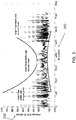
FIG. 3 illustrates an exemplary amplitude plot that indicates acoustic levels according to embodiments of the invention; -
FIG. 4 illustrates an exemplary amplitude plot that indicates strain, which is proportional to acoustic levels, according to an embodiment of the invention; and -
FIG. 5 is a process flow of a method of determining acoustic level using the DAS system according to embodiments of the invention. - As noted above, a distributed acoustic sensing (DAS) system may be used to obtain acoustic information and other information in a given environment. An exemplary application is a downhole exploration or production effort. Typically, the DAS signal (return based on transmitting light into the optical fiber) includes a low frequency component that is largely due to temperature changes and a high frequency component due to acoustic sources. Embodiments of the systems and methods described herein relate to processing the low frequency component to obtain acoustic levels. According to the embodiments, low pulse repetition rates may be used such that overall data volume may be reduced.
-
FIG. 1 is a cross-sectional illustration of aborehole 1 and a distributed acoustic sensing (DAS)system 100 according to embodiments of the invention. The arrangement shown inFIG. 1 is one exemplary use of theDAS system 100. While theDAS system 100 may be used in other environments and in other sub-surface arrangements, theexemplary DAS system 100 shown inFIG. 1 is arranged to measure acoustic levels in aborehole 1 penetrating theearth 3 including aformation 4. A set oftools 10 may be lowered into theborehole 1 by astring 2. In embodiments of the invention, thestring 2 may be a casing string, production string, an armored wireline, a slickline, coiled tubing, or a work string. In measure-while-drilling (MWD) embodiments, thestring 2 may be a drill string, and a drill would be included below thetools 10. Information from the sensors and measurement devices included in the set oftools 10 may be sent to the surface for processing by thesurface processing system 130 via a fiber link or telemetry. The surface processing system 130 (e.g., computing device) includes one or more processors and one or more memory devices in addition to an input interface and an output device. TheDAS system 100 includes an optical fiber 110 (the device under test, DUT). Embodiments of theoptical fiber 110 are further detailed below. TheDAS system 100 also includes asurface interrogation unit 120, further discussed with reference toFIG. 2 . -
FIG. 2 details theDAS system 100 shown inFIG. 1 according to the invention. TheDAS system 100 includes aninterrogation unit 120, alight source 210, and one ormore photodetectors 220 to receive the reflected signals or scatter from theoptical fiber 110. Theinterrogation unit 120 may be disposed at the surface in the exemplary embodiment shown inFIG. 1 . Theinterrogation unit 120 includes aprocessing system 230 with one or more processors and memory devices to process the scatter resulting from illuminating theoptical fiber 110 with afiber core 117. Alternately, thephotodetectors 220 may output the reflection information to thesurface processing system 130 for processing. Theinterrogation unit 120 typically includes additional elements such as a circulator (not shown) to direct light from thelight source 210 into theoptical fiber 110 and scatter or reflection generated in theoptical fiber 110 to the one ormore photodetectors 220. The light source may be a coherent light source in which light waves are in phase with one another. According to one embodiment, thelight source 210 may be a laser and may emit pulses of light at the same wavelength and amplitude. According to an alternate embodiment, thelight source 210 may be a swept-wavelength laser and may emit pulses of light having a range of wavelengths. Thephotodetector 220 detects a DAS signal resulting from the incident light pulses being emitted into theoptical fiber 110. According to an embodiment of the invention, the DAS signal is a measure of interference among the Rayleigh scatter originating from multiple nearby points in theoptical fiber 110 over time (a number of samples of interference signals from a particular length of the optical fiber 110). According to another embodiment, the DAS signal is a measure of interference among reflections resulting from fiber Bragg gratings (FBGs) within theoptical fiber 110. The DAS signal is processed to determine the acoustic information as detailed below. - The processing of the DAS signal to obtain acoustic information is based on a recognition that the amplitude of the low frequency DAS signal (used to determine temperature) may be used to map acoustic intensity. The low frequency DAS signal generally refers to the portion or component of the DAS signal that is less than 10 Hertz (Hz). The frequency of this low frequency component decreases as pulse width of the light pulse transmitted by the
light source 210 decreases. The DAS signal may be modeled as a Fabry-Perot interferometer and is given by:
photodetector 220. L is the pulse length of the light pulse emitted by the light source 210 (e.g., laser), λ is the wavelength of the light emitted by thelight source 210 at the given instant of time t. Over a period of time, the value of λ may be constant according to one embodiment or may vary over a range of wavelengths (may sweep a range of wavelengths) according to another embodiment. n0 is the refractive index of theoptical fiber 110. dn/dT is the change in the refractive index with temperature and is approximately 1e-5 per degree Celsius (°C-1). ΔT(t) is the time dependent change in temperature, and ε(t) is the time dependent strain. This time dependent strain component provides the acoustic information. TheDAS system 100 only measures the real component of the DAS signal, but the ideal signal produced in the optical fiber 110 (e.g., by Rayleigh scatter) is a complex number. The imaginary portion of the DAS signal may be approximated using a Hilbert transform of thephotodetector 220 measured data as:


optical fiber 110 are determined based on the amplitude of the temperature induced signals (e.g., Rayleigh scatter). - When the wavelength λ is changing over time based on the embodiment that uses a swept-wavelength laser, for example, EQ. 1 may be used to derive EQ. 4 and obtain acoustic levels regardless of whether temperature is constant or changing over time. However, when the wavelength is constant based on the embodiment that uses a constant wavelength
light source 210, if the temperature is constant (ΔT(t)=0), then the DAS signal does not include a low frequency component due to temperature effects, and EQ. 4 cannot be used to easily obtain the acoustic levels. When EQ. 4 is used to obtain the acoustic levels (because temperature is not constant or because a swept-wavelength light source 210 is used) instead of using high frequency components, as is currently done, then relatively much lower data acquisition rates may be used, and acoustic monitoring is facilitated over relatively much longer distances. As an example, a typical DAS data sampling rate may be 5 kilo Hertz (kHz) while theDAS system 100 according to embodiments discussed herein may acquire the DAS signal (e.g., Rayleigh scatter) at 50 Hz, thereby facilitating the storage and processing of a much lower volume of data. In addition, the typical DAS data sampling rate would suffer from the effects of aliasing if low data acquisition rates were used to monitor acoustics over long distances. However, theDAS system 100 described herein facilitates monitoring acoustic levels over long distances. This is because, when using theDAS system 100 to monitor broadband flow noise in theborehole 1, for example, the low frequency monitoring described above should be relatively insensitive to aliasing. -
FIG. 3 illustrates an exemplary amplitude plot that indicates acoustic levels according to embodiments of the invention. InFIG. 3 , time is shown along theaxis 310, and average DAS amplitude, the time-averaged amplitude of the interference of Rayleigh scatter signals resulting from two or more points in a length of theoptical fiber 110, is shown along theaxis 320. High acoustic levels are indicated by relatively smaller fringe depth and low acoustic levels are indicated by relatively larger fringe depth, as shown. That is, EQ. 1 involves non-linear frequency mixing between low frequency temperature induced signals and higher frequency acoustic signals. As the acoustic levels increase in amplitude, the level of mixing increases such that the low frequency signals get mixed up to higher frequencies. For example, if theDAS system 100 is measuring an acoustic signal at 100 Hz and a temperature change is causing a low frequency component at 1 Hz, at low acoustic amplitudes, theDAS system 100 will measure the 1 Hz and the 100 Hz components at their correct frequencies. As the acoustic signal amplitude increases, frequency mixing occurs, resulting in sum and difference frequencies (99Hz and 101 Hz) in addition to the true signals at 1 Hz and 100 Hz. Above a certain amplitude for the acoustic signal, the signals at 1 Hz and 100 Hz are completed converted into the sum and difference frequencies (99 Hz and 101 Hz), and the low frequency (1 Hz) is no longer measured. This depletion of low frequency signals facilitates the low frequency signals becoming sensitive to the level of the high frequency acoustic signals. The Rayleigh backscatter originating from the multiple proximate pointson theoptical fiber 110 is oscillatory as a function of time. The depth of the oscillations is inversely proportional to the acoustic strain applied to theoptical fiber 110, as illustrated inFIG. 4 . -
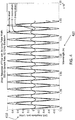
FIG. 4 illustrates an exemplary amplitude plot that indicates strain, which is proportional to acoustic levels, according to an embodiment of the invention. The DAS amplitude, indicated on theaxis 410, is obtained for a variable wavelength, indicated on theaxis 420, that is swept (varied over a range of values). The DAS signal is obtained with a 500 Hz sample rate, and the acoustic strain is a sine wave of 52.12 Hz. AsFIG. 4 illustrates, as the strain increases, the DAS amplitude decreases. The strain, which affects the DAS amplitude, is an indicator of the acoustic level at the point along theoptical fiber 110 at which the DAS signal (interference of Rayleigh scatter) originated. In the case of using alight source 210 with a swept wavelength, the frequency of the DAS signal is controlled through the wavelength sweep rate. Thus, recovery of the low frequency component of the DAS signal may not be necessary because the DAS signal may be a low frequency signal. In that case, the acoustic amplitude is recovered through the fringe depth related to the entire DAS signal. The processing described above with reference to a length (of proximate points) on theoptical fiber 110 may be repeated at different areas or sections (interference signals from different sections along theoptical fiber 110 may be measured) such that acoustic levels at different periodic or random intervals along theoptical fiber 110 may be monitored. -
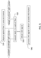
FIG. 5 is a process flow of a method of determining acoustic level using theDAS system 100 according to embodiments of the invention. Atblock 510, disposing theoptical fiber 110 in the area of interest includes disposing theoptical fiber 110 in aborehole 1 or another area in which acoustic levels are to be measured and monitored. Atblock 520, transmitting light into theoptical fiber 110 includes using a constant wavelengthlight source 210 or a swept wavelengthlight source 210. When the temperature is constant, the swept wavelengthlight source 210 must be used to obtain acoustic levels according to EQ. 4. While the embodiment detailed herein for interrogating theoptical fiber 110 with thelight source 210 to generate the DAS signal relates to optical time domain reflectometry (OTDR), optical frequency domain reflectometry (OFDR) may be used in alternate embodiments. Once the DAS signal is obtained, the processing described herein to obtain the acoustic levels applies to both embodiments. Atblock 530, obtaining the DAS signal includes one ormore photodetectors 220 measuring interference of Rayleigh backscatter or reflections originating at two or more points within a given length along theoptical fiber 110 based on the incident light transmitted into theoptical fiber 110. Atblock 540, processing the DAS signal to obtain acoustic information (in the given area) includes using EQ. 4 to determine acoustic levels based on amplitude as shown in exemplaryFIGs. 3 and4 . As noted above, when the DAS signal is obtained in more than one area of theoptical fiber 110, the acoustic levels at the multiple areas of theoptical fiber 110 may be determined and monitored. - While one or more embodiments have been shown and described, modifications may be made thereto without departing from the scope of the invention as defined by the appended claims.
Claims (14)
- A distributed acoustic sensing, DAS, system (100) to obtain acoustic levels, comprising:an optical fiber (110);a light source (210) configured to inject light into the optical fiber (110);a photodetector (220) configured to sample a DAS signal in each section of one or more sections of the optical fiber (110) resulting from two or more points within the section on the optical fiber (110) over a period of time; anda processor (230, 130) configured to process only a low frequency portion of the DAS signal to obtain the acoustic levels at each of the one or more sections on the optical fiber (110) over the period of time, the low frequency portion of the DAS signal being less than 10 Hz;characterized in that:the processor (230, 130) is configured to obtain the acoustic levels at each of the one or more sections based on:
 where DAS' = DAS + i∗Hilbert(DAS),Hilbert(DAS) is the Hilbert transform of the DAS signal, Temp is a temperature component of the DAS signal, Acoust is an acoustic component of the DAS signal, and B is a constant.
 - The system according to claim 1, wherein the light source (210) is configured to emit light pulses at a constant wavelength.
- The system according to claim 2, wherein the light source (210) is configured to emit the light pulses at the constant wavelength when temperature varies over time at the two or more points of the one or more sections of the optical fiber (110).
- The system according to claim 1, wherein the light source (210) is configured to emit pulses of light that sweep a range of wavelengths.
- The system according to claim 1, wherein the photodetector (220) is configured to sample the DAS signal at each section of the one or more sections of the optical fiber (110) by measuring interference between an intensity of Rayleigh backscatter originating at the two or more points within the section of the optical fiber (110).
- The system according to claim 1, wherein the photodetector (220) is configured to sample the DAS signal at each section of the one or more sections of the optical fiber (110) by measuring interference between an intensity of reflections originating at the two or more points within the section of the optical fiber (110).
- The system according to claim 1, wherein the DAS signal at each of the one or more areas resulting from the two or more points is given by:

- The system according to claim 1, wherein the optical fiber (110) is disposed in a borehole (1), and the processor (230, 130) is configured to determine the acoustic levels at one or more sections along the optical fiber (110) corresponding with one or more positions in the borehole (1).
- A method of obtaining acoustic levels using a distributed acoustic sensing, DAS,
system (100), the method comprising:disposing an optical fiber (110) in an area in which the acoustic levels are to be determined (510);injecting light into the optical fiber (110) with a light source (210) (520);sampling, using a photodetector (220), a DAS signal at each section of one or more sections of the optical fiber (110) originating from two or more points within the section of the optical fiber (110) over a period of time (530); andprocessing, using a processor (230, 130), only a low frequency portion of the DAS signal, the processing including obtaining the acoustic levels at each of the one or more sections of the optical fiber (110) over the period of time, the low frequency portion of the DAS signal being less than 10 Hz (540);characterized in that:the processor (230, 130) obtaining the acoustic levels at each of the one or more sections is based on: where DAS' = DAS + i∗Hilbert(DAS),Hilbert(DAS) is the Hilbert transform of the DAS signal, Temp is a temperature component of the DAS signal, Acoust is an acoustic component of the DAS signal, and B is a constant.
 - The method according to claim 9, wherein the injecting the light includes emitting light pulses at a constant wavelength.
- The method according to claim 10, wherein the emitting the light pulses at the constant wavelength is done when temperature values vary over time at the two or more points of the one or more sections of the optical fiber (110).
- The method according to claim 9, wherein the injecting the light includes emitting pulses of light that sweep a range of wavelengths.
- The method according to claim 9, wherein the photodetector (220) sampling the DAS signal at each section of the one or more sections includes the photodetector (220) measuring interference of an intensity of Rayleigh backscatter originating at the two or more points within the section of the optical fiber (110).
- The method according to claim 9, wherein the protodetector (220) sampling the DAS signal at each section of the one or more sections includes the photodetector (220) measuring interference of an intensity of reflections originating at the two or more points within the section of the optical fiber (110).
Applications Claiming Priority (2)
| Application Number | Priority Date | Filing Date | Title |
|---|---|---|---|
| US201461986217P | 2014-04-30 | 2014-04-30 | |
| PCT/US2015/022425 WO2015167701A1 (en) | 2014-04-30 | 2015-03-25 | Distributed acoustic sensing using low pulse repetition rates |
Publications (3)
| Publication Number | Publication Date |
|---|---|
| EP3137735A1 EP3137735A1 (en) | 2017-03-08 |
| EP3137735A4 EP3137735A4 (en) | 2018-01-10 |
| EP3137735B1 true EP3137735B1 (en) | 2021-08-04 |
Family
ID=54355986
Family Applications (1)
| Application Number | Title | Priority Date | Filing Date |
|---|---|---|---|
| EP15785873.9A Active EP3137735B1 (en) | 2014-04-30 | 2015-03-25 | Distributed acoustic sensing using low pulse repetition rates |
Country Status (4)
| Country | Link |
|---|---|
| US (1) | US9634766B2 (en) |
| EP (1) | EP3137735B1 (en) |
| CA (1) | CA2946279C (en) |
| WO (1) | WO2015167701A1 (en) |
Families Citing this family (12)
| Publication number | Priority date | Publication date | Assignee | Title |
|---|---|---|---|---|
| US11698288B2 (en) | 2018-11-14 | 2023-07-11 | Saudi Arabian Oil Company | Signal to noise ratio management |
| EP3757523B1 (en) * | 2019-06-28 | 2022-08-03 | Alcatel Submarine Networks | Method and apparatus for suppression of noise due to transmitted signal instability in a coherent fiber optical sensor system |
| US11339636B2 (en) | 2020-05-04 | 2022-05-24 | Saudi Arabian Oil Company | Determining the integrity of an isolated zone in a wellbore |
| US11519767B2 (en) | 2020-09-08 | 2022-12-06 | Saudi Arabian Oil Company | Determining fluid parameters |
| US11920469B2 (en) | 2020-09-08 | 2024-03-05 | Saudi Arabian Oil Company | Determining fluid parameters |
| US20220128383A1 (en) * | 2020-10-08 | 2022-04-28 | Nec Laboratories America, Inc | OTDR measurement via wavelength/frequency sweeping in phase-sensitive DAS/DVS systems |
| US11530597B2 (en) | 2021-02-18 | 2022-12-20 | Saudi Arabian Oil Company | Downhole wireless communication |
| US11603756B2 (en) | 2021-03-03 | 2023-03-14 | Saudi Arabian Oil Company | Downhole wireless communication |
| US11644351B2 (en) | 2021-03-19 | 2023-05-09 | Saudi Arabian Oil Company | Multiphase flow and salinity meter with dual opposite handed helical resonators |
| US11913464B2 (en) | 2021-04-15 | 2024-02-27 | Saudi Arabian Oil Company | Lubricating an electric submersible pump |
| US11619114B2 (en) | 2021-04-15 | 2023-04-04 | Saudi Arabian Oil Company | Entering a lateral branch of a wellbore with an assembly |
| US20230122262A1 (en) * | 2021-10-15 | 2023-04-20 | Nec Laboratories America, Inc | Distributed acoustic sensing sensitivity enhancement using mimo sampling and phase recombination |
Family Cites Families (13)
| Publication number | Priority date | Publication date | Assignee | Title |
|---|---|---|---|---|
| US6763306B2 (en) * | 2002-11-18 | 2004-07-13 | The United States Of America As Represented By The Secretary Of The Navy | Method of using ocean acoustic sensors for coastal earthquake prediction |
| US8379297B2 (en) * | 2006-05-30 | 2013-02-19 | Weatherford/Lamb, Inc. | Wavelength swept light source and filter based on sweep function, and its method of operation |
| US7719923B2 (en) | 2006-06-05 | 2010-05-18 | Westerngeco L.L.C. | Low frequency model estimation |
| US8737165B2 (en) | 2010-10-01 | 2014-05-27 | Westerngeco L.L.C. | Interferometric seismic data processing for a towed marine survey |
| WO2012054635A2 (en) | 2010-10-19 | 2012-04-26 | Weatherford/Lamb, Inc. | Monitoring using distributed acoustic sensing (das) technology |
| WO2012087604A2 (en) * | 2010-12-21 | 2012-06-28 | Shell Oil Company | System and method for moniitoring strain & pressure |
| GB201104423D0 (en) | 2011-03-16 | 2011-04-27 | Qinetiq Ltd | Subsurface monitoring using distributed accoustic sensors |
| US20130113629A1 (en) * | 2011-11-04 | 2013-05-09 | Schlumberger Technology Corporation | Phase sensitive coherent otdr with multi-frequency interrogation |
| GB201212701D0 (en) * | 2012-07-17 | 2012-08-29 | Silixa Ltd | Structure monitoring |
| US9677957B2 (en) * | 2012-11-27 | 2017-06-13 | Senek Instrument LLC | Serial fiber Bragg grating interrogator with a pulsed laser for reflection spectrum measurement |
| EP3450678B1 (en) * | 2013-01-16 | 2020-01-15 | Saudi Arabian Oil Company | Method and apparatus for in-well wireless control using infrasound sources |
| WO2014201313A1 (en) * | 2013-06-13 | 2014-12-18 | Schlumberger Canada Limited | Fiber optic distributed vibration sensing with directional sensitivity |
| GB2515564A (en) * | 2013-06-28 | 2014-12-31 | Optasense Holdings Ltd | Improvements in fibre optic distributed sensing |
-
2015
- 2015-03-20 US US14/664,277 patent/US9634766B2/en active Active
- 2015-03-25 WO PCT/US2015/022425 patent/WO2015167701A1/en active Application Filing
- 2015-03-25 EP EP15785873.9A patent/EP3137735B1/en active Active
- 2015-03-25 CA CA2946279A patent/CA2946279C/en active Active
Also Published As
| Publication number | Publication date |
|---|---|
| CA2946279C (en) | 2018-11-06 |
| US9634766B2 (en) | 2017-04-25 |
| WO2015167701A1 (en) | 2015-11-05 |
| EP3137735A1 (en) | 2017-03-08 |
| EP3137735A4 (en) | 2018-01-10 |
| CA2946279A1 (en) | 2015-11-05 |
| US20150318920A1 (en) | 2015-11-05 |
Similar Documents
| Publication | Publication Date | Title |
|---|---|---|
| EP3137735B1 (en) | Distributed acoustic sensing using low pulse repetition rates | |
| US10208586B2 (en) | Temperature sensing using distributed acoustic sensing | |
| AU2017230721B2 (en) | Measuring downhole temperature by combining DAS/DTS data | |
| EP3111042B1 (en) | Distributed acoustic sensing gauge length effect mitigation | |
| EP3134615B1 (en) | Attenuation correction for distributed temperature sensors using antistokes to rayleigh ratio | |
| CA3055290C (en) | Measurement of temperature using combination of rayleigh and raman backscatter interferometry | |
| AU2012321271B2 (en) | Distance measurement using incoherent optical reflectometry | |
| US20120237205A1 (en) | System and method to compensate for arbitrary optical fiber lead-ins in an optical frequency domain reflectometry system | |
| CA2874446C (en) | Depth correction based on optical path measurements | |
| EP3132239B1 (en) | Distributed temperature sensor enhancement by stimulated raman suppression | |
| NO20160605A1 (en) | Use of Bragg Gratings with Coherent OTDR |
Legal Events
| Date | Code | Title | Description |
|---|---|---|---|
| STAA | Information on the status of an ep patent application or granted ep patent |
Free format text: STATUS: THE INTERNATIONAL PUBLICATION HAS BEEN MADE |
|
| PUAI | Public reference made under article 153(3) epc to a published international application that has entered the european phase |
Free format text: ORIGINAL CODE: 0009012 |
|
| STAA | Information on the status of an ep patent application or granted ep patent |
Free format text: STATUS: REQUEST FOR EXAMINATION WAS MADE |
|
| 17P | Request for examination filed |
Effective date: 20161118 |
|
| AK | Designated contracting states |
Kind code of ref document: A1 Designated state(s): AL AT BE BG CH CY CZ DE DK EE ES FI FR GB GR HR HU IE IS IT LI LT LU LV MC MK MT NL NO PL PT RO RS SE SI SK SM TR |
|
| AX | Request for extension of the european patent |
Extension state: BA ME |
|
| RIN1 | Information on inventor provided before grant (corrected) |
Inventor name: JOHNSTON, WILLIAM |
|
| DAV | Request for validation of the european patent (deleted) | ||
| DAX | Request for extension of the european patent (deleted) | ||
| REG | Reference to a national code |
Ref country code: DE Ref legal event code: R079 Ref document number: 602015071960 Country of ref document: DE Free format text: PREVIOUS MAIN CLASS: E21B0047000000 Ipc: G01V0001220000 |
|
| A4 | Supplementary search report drawn up and despatched |
Effective date: 20171213 |
|
| RIC1 | Information provided on ipc code assigned before grant |
Ipc: G01V 1/22 20060101AFI20171207BHEP Ipc: H04B 10/25 20130101ALI20171207BHEP |
|
| GRAP | Despatch of communication of intention to grant a patent |
Free format text: ORIGINAL CODE: EPIDOSNIGR1 |
|
| STAA | Information on the status of an ep patent application or granted ep patent |
Free format text: STATUS: GRANT OF PATENT IS INTENDED |
|
| INTG | Intention to grant announced |
Effective date: 20210304 |
|
| RAP3 | Party data changed (applicant data changed or rights of an application transferred) |
Owner name: BAKER HUGHES HOLDINGS LLC |
|
| GRAS | Grant fee paid |
Free format text: ORIGINAL CODE: EPIDOSNIGR3 |
|
| GRAA | (expected) grant |
Free format text: ORIGINAL CODE: 0009210 |
|
| STAA | Information on the status of an ep patent application or granted ep patent |
Free format text: STATUS: THE PATENT HAS BEEN GRANTED |
|
| AK | Designated contracting states |
Kind code of ref document: B1 Designated state(s): AL AT BE BG CH CY CZ DE DK EE ES FI FR GB GR HR HU IE IS IT LI LT LU LV MC MK MT NL NO PL PT RO RS SE SI SK SM TR |
|
| REG | Reference to a national code |
Ref country code: GB Ref legal event code: FG4D |
|
| REG | Reference to a national code |
Ref country code: AT Ref legal event code: REF Ref document number: 1417530 Country of ref document: AT Kind code of ref document: T Effective date: 20210815 |
|
| REG | Reference to a national code |
Ref country code: CH Ref legal event code: EP |
|
| REG | Reference to a national code |
Ref country code: DE Ref legal event code: R096 Ref document number: 602015071960 Country of ref document: DE |
|
| REG | Reference to a national code |
Ref country code: IE Ref legal event code: FG4D |
|
| REG | Reference to a national code |
Ref country code: LT Ref legal event code: MG9D |
|
| REG | Reference to a national code |
Ref country code: NL Ref legal event code: MP Effective date: 20210804 |
|
| REG | Reference to a national code |
Ref country code: AT Ref legal event code: MK05 Ref document number: 1417530 Country of ref document: AT Kind code of ref document: T Effective date: 20210804 |
|
| REG | Reference to a national code |
Ref country code: NO Ref legal event code: T2 Effective date: 20210804 |
|
| PG25 | Lapsed in a contracting state [announced via postgrant information from national office to epo] |
Ref country code: HR Free format text: LAPSE BECAUSE OF FAILURE TO SUBMIT A TRANSLATION OF THE DESCRIPTION OR TO PAY THE FEE WITHIN THE PRESCRIBED TIME-LIMIT Effective date: 20210804 Ref country code: SE Free format text: LAPSE BECAUSE OF FAILURE TO SUBMIT A TRANSLATION OF THE DESCRIPTION OR TO PAY THE FEE WITHIN THE PRESCRIBED TIME-LIMIT Effective date: 20210804 Ref country code: RS Free format text: LAPSE BECAUSE OF FAILURE TO SUBMIT A TRANSLATION OF THE DESCRIPTION OR TO PAY THE FEE WITHIN THE PRESCRIBED TIME-LIMIT Effective date: 20210804 Ref country code: FI Free format text: LAPSE BECAUSE OF FAILURE TO SUBMIT A TRANSLATION OF THE DESCRIPTION OR TO PAY THE FEE WITHIN THE PRESCRIBED TIME-LIMIT Effective date: 20210804 Ref country code: ES Free format text: LAPSE BECAUSE OF FAILURE TO SUBMIT A TRANSLATION OF THE DESCRIPTION OR TO PAY THE FEE WITHIN THE PRESCRIBED TIME-LIMIT Effective date: 20210804 Ref country code: PT Free format text: LAPSE BECAUSE OF FAILURE TO SUBMIT A TRANSLATION OF THE DESCRIPTION OR TO PAY THE FEE WITHIN THE PRESCRIBED TIME-LIMIT Effective date: 20211206 Ref country code: LT Free format text: LAPSE BECAUSE OF FAILURE TO SUBMIT A TRANSLATION OF THE DESCRIPTION OR TO PAY THE FEE WITHIN THE PRESCRIBED TIME-LIMIT Effective date: 20210804 Ref country code: AT Free format text: LAPSE BECAUSE OF FAILURE TO SUBMIT A TRANSLATION OF THE DESCRIPTION OR TO PAY THE FEE WITHIN THE PRESCRIBED TIME-LIMIT Effective date: 20210804 Ref country code: BG Free format text: LAPSE BECAUSE OF FAILURE TO SUBMIT A TRANSLATION OF THE DESCRIPTION OR TO PAY THE FEE WITHIN THE PRESCRIBED TIME-LIMIT Effective date: 20211104 |
|
| PG25 | Lapsed in a contracting state [announced via postgrant information from national office to epo] |
Ref country code: PL Free format text: LAPSE BECAUSE OF FAILURE TO SUBMIT A TRANSLATION OF THE DESCRIPTION OR TO PAY THE FEE WITHIN THE PRESCRIBED TIME-LIMIT Effective date: 20210804 Ref country code: LV Free format text: LAPSE BECAUSE OF FAILURE TO SUBMIT A TRANSLATION OF THE DESCRIPTION OR TO PAY THE FEE WITHIN THE PRESCRIBED TIME-LIMIT Effective date: 20210804 Ref country code: GR Free format text: LAPSE BECAUSE OF FAILURE TO SUBMIT A TRANSLATION OF THE DESCRIPTION OR TO PAY THE FEE WITHIN THE PRESCRIBED TIME-LIMIT Effective date: 20211105 |
|
| PG25 | Lapsed in a contracting state [announced via postgrant information from national office to epo] |
Ref country code: NL Free format text: LAPSE BECAUSE OF FAILURE TO SUBMIT A TRANSLATION OF THE DESCRIPTION OR TO PAY THE FEE WITHIN THE PRESCRIBED TIME-LIMIT Effective date: 20210804 |
|
| PG25 | Lapsed in a contracting state [announced via postgrant information from national office to epo] |
Ref country code: DK Free format text: LAPSE BECAUSE OF FAILURE TO SUBMIT A TRANSLATION OF THE DESCRIPTION OR TO PAY THE FEE WITHIN THE PRESCRIBED TIME-LIMIT Effective date: 20210804 |
|
| REG | Reference to a national code |
Ref country code: DE Ref legal event code: R097 Ref document number: 602015071960 Country of ref document: DE |
|
| PG25 | Lapsed in a contracting state [announced via postgrant information from national office to epo] |
Ref country code: SM Free format text: LAPSE BECAUSE OF FAILURE TO SUBMIT A TRANSLATION OF THE DESCRIPTION OR TO PAY THE FEE WITHIN THE PRESCRIBED TIME-LIMIT Effective date: 20210804 Ref country code: SK Free format text: LAPSE BECAUSE OF FAILURE TO SUBMIT A TRANSLATION OF THE DESCRIPTION OR TO PAY THE FEE WITHIN THE PRESCRIBED TIME-LIMIT Effective date: 20210804 Ref country code: RO Free format text: LAPSE BECAUSE OF FAILURE TO SUBMIT A TRANSLATION OF THE DESCRIPTION OR TO PAY THE FEE WITHIN THE PRESCRIBED TIME-LIMIT Effective date: 20210804 Ref country code: EE Free format text: LAPSE BECAUSE OF FAILURE TO SUBMIT A TRANSLATION OF THE DESCRIPTION OR TO PAY THE FEE WITHIN THE PRESCRIBED TIME-LIMIT Effective date: 20210804 Ref country code: CZ Free format text: LAPSE BECAUSE OF FAILURE TO SUBMIT A TRANSLATION OF THE DESCRIPTION OR TO PAY THE FEE WITHIN THE PRESCRIBED TIME-LIMIT Effective date: 20210804 Ref country code: AL Free format text: LAPSE BECAUSE OF FAILURE TO SUBMIT A TRANSLATION OF THE DESCRIPTION OR TO PAY THE FEE WITHIN THE PRESCRIBED TIME-LIMIT Effective date: 20210804 |
|
| PLBE | No opposition filed within time limit |
Free format text: ORIGINAL CODE: 0009261 |
|
| STAA | Information on the status of an ep patent application or granted ep patent |
Free format text: STATUS: NO OPPOSITION FILED WITHIN TIME LIMIT |
|
| 26N | No opposition filed |
Effective date: 20220506 |
|
| PG25 | Lapsed in a contracting state [announced via postgrant information from national office to epo] |
Ref country code: IT Free format text: LAPSE BECAUSE OF FAILURE TO SUBMIT A TRANSLATION OF THE DESCRIPTION OR TO PAY THE FEE WITHIN THE PRESCRIBED TIME-LIMIT Effective date: 20210804 |
|
| PG25 | Lapsed in a contracting state [announced via postgrant information from national office to epo] |
Ref country code: SI Free format text: LAPSE BECAUSE OF FAILURE TO SUBMIT A TRANSLATION OF THE DESCRIPTION OR TO PAY THE FEE WITHIN THE PRESCRIBED TIME-LIMIT Effective date: 20210804 |
|
| REG | Reference to a national code |
Ref country code: DE Ref legal event code: R119 Ref document number: 602015071960 Country of ref document: DE |
|
| PG25 | Lapsed in a contracting state [announced via postgrant information from national office to epo] |
Ref country code: MC Free format text: LAPSE BECAUSE OF FAILURE TO SUBMIT A TRANSLATION OF THE DESCRIPTION OR TO PAY THE FEE WITHIN THE PRESCRIBED TIME-LIMIT Effective date: 20210804 |
|
| REG | Reference to a national code |
Ref country code: CH Ref legal event code: PL |
|
| REG | Reference to a national code |
Ref country code: BE Ref legal event code: MM Effective date: 20220331 |
|
| PG25 | Lapsed in a contracting state [announced via postgrant information from national office to epo] |
Ref country code: LU Free format text: LAPSE BECAUSE OF NON-PAYMENT OF DUE FEES Effective date: 20220325 Ref country code: LI Free format text: LAPSE BECAUSE OF NON-PAYMENT OF DUE FEES Effective date: 20220331 Ref country code: IE Free format text: LAPSE BECAUSE OF NON-PAYMENT OF DUE FEES Effective date: 20220325 Ref country code: FR Free format text: LAPSE BECAUSE OF NON-PAYMENT OF DUE FEES Effective date: 20220331 Ref country code: DE Free format text: LAPSE BECAUSE OF NON-PAYMENT OF DUE FEES Effective date: 20221001 Ref country code: CH Free format text: LAPSE BECAUSE OF NON-PAYMENT OF DUE FEES Effective date: 20220331 |
|
| PG25 | Lapsed in a contracting state [announced via postgrant information from national office to epo] |
Ref country code: BE Free format text: LAPSE BECAUSE OF NON-PAYMENT OF DUE FEES Effective date: 20220331 |
|
| PGFP | Annual fee paid to national office [announced via postgrant information from national office to epo] |
Ref country code: NO Payment date: 20230223 Year of fee payment: 9 |
|
| P01 | Opt-out of the competence of the unified patent court (upc) registered |
Effective date: 20230526 |
|
| PG25 | Lapsed in a contracting state [announced via postgrant information from national office to epo] |
Ref country code: HU Free format text: LAPSE BECAUSE OF FAILURE TO SUBMIT A TRANSLATION OF THE DESCRIPTION OR TO PAY THE FEE WITHIN THE PRESCRIBED TIME-LIMIT; INVALID AB INITIO Effective date: 20150325 |
|
| PG25 | Lapsed in a contracting state [announced via postgrant information from national office to epo] |
Ref country code: MK Free format text: LAPSE BECAUSE OF FAILURE TO SUBMIT A TRANSLATION OF THE DESCRIPTION OR TO PAY THE FEE WITHIN THE PRESCRIBED TIME-LIMIT Effective date: 20210804 Ref country code: CY Free format text: LAPSE BECAUSE OF FAILURE TO SUBMIT A TRANSLATION OF THE DESCRIPTION OR TO PAY THE FEE WITHIN THE PRESCRIBED TIME-LIMIT Effective date: 20210804 |
|
| PGFP | Annual fee paid to national office [announced via postgrant information from national office to epo] |
Ref country code: GB Payment date: 20240221 Year of fee payment: 10 |