EP3126783B1 - Device for measuring at least one physical quantity of an electric installation - Google Patents
Device for measuring at least one physical quantity of an electric installation Download PDFInfo
- Publication number
- EP3126783B1 EP3126783B1 EP15719789.8A EP15719789A EP3126783B1 EP 3126783 B1 EP3126783 B1 EP 3126783B1 EP 15719789 A EP15719789 A EP 15719789A EP 3126783 B1 EP3126783 B1 EP 3126783B1
- Authority
- EP
- European Patent Office
- Prior art keywords
- sensor
- current
- conductors
- pair
- voltage
- Prior art date
- Legal status (The legal status is an assumption and is not a legal conclusion. Google has not performed a legal analysis and makes no representation as to the accuracy of the status listed.)
- Active
Links
- 238000009434 installation Methods 0.000 title claims description 10
- 238000005259 measurement Methods 0.000 claims description 89
- 239000004020 conductor Substances 0.000 claims description 87
- 238000004891 communication Methods 0.000 claims description 41
- 238000012545 processing Methods 0.000 claims description 36
- 238000010616 electrical installation Methods 0.000 claims description 32
- 230000000295 complement effect Effects 0.000 claims description 18
- 101150066284 DET2 gene Proteins 0.000 claims description 16
- 102000012677 DET1 Human genes 0.000 claims description 14
- 101150113651 DET1 gene Proteins 0.000 claims description 14
- 230000000875 corresponding effect Effects 0.000 claims description 12
- 238000000034 method Methods 0.000 claims description 7
- 230000002441 reversible effect Effects 0.000 claims description 6
- 238000011144 upstream manufacturing Methods 0.000 claims description 5
- 230000008569 process Effects 0.000 claims description 4
- 230000002596 correlated effect Effects 0.000 claims description 2
- XEEYBQQBJWHFJM-UHFFFAOYSA-N Iron Chemical compound [Fe] XEEYBQQBJWHFJM-UHFFFAOYSA-N 0.000 description 4
- 230000005540 biological transmission Effects 0.000 description 4
- 238000005516 engineering process Methods 0.000 description 4
- 238000001514 detection method Methods 0.000 description 3
- 238000004458 analytical method Methods 0.000 description 2
- 238000010586 diagram Methods 0.000 description 2
- 230000000694 effects Effects 0.000 description 2
- 229910052742 iron Inorganic materials 0.000 description 2
- 230000005355 Hall effect Effects 0.000 description 1
- PXHVJJICTQNCMI-UHFFFAOYSA-N Nickel Chemical group [Ni] PXHVJJICTQNCMI-UHFFFAOYSA-N 0.000 description 1
- XUIMIQQOPSSXEZ-UHFFFAOYSA-N Silicon Chemical group [Si] XUIMIQQOPSSXEZ-UHFFFAOYSA-N 0.000 description 1
- 240000008042 Zea mays Species 0.000 description 1
- 238000013459 approach Methods 0.000 description 1
- 230000002457 bidirectional effect Effects 0.000 description 1
- 238000007664 blowing Methods 0.000 description 1
- 239000003990 capacitor Substances 0.000 description 1
- 230000001427 coherent effect Effects 0.000 description 1
- 238000010276 construction Methods 0.000 description 1
- 238000012937 correction Methods 0.000 description 1
- 230000008878 coupling Effects 0.000 description 1
- 238000010168 coupling process Methods 0.000 description 1
- 238000005859 coupling reaction Methods 0.000 description 1
- 238000013461 design Methods 0.000 description 1
- 238000011161 development Methods 0.000 description 1
- 230000005684 electric field Effects 0.000 description 1
- 238000011156 evaluation Methods 0.000 description 1
- 238000001914 filtration Methods 0.000 description 1
- 230000036039 immunity Effects 0.000 description 1
- 230000010354 integration Effects 0.000 description 1
- 239000000696 magnetic material Substances 0.000 description 1
- 238000004519 manufacturing process Methods 0.000 description 1
- 238000012986 modification Methods 0.000 description 1
- 230000004048 modification Effects 0.000 description 1
- 238000012544 monitoring process Methods 0.000 description 1
- 230000010363 phase shift Effects 0.000 description 1
- 230000035945 sensitivity Effects 0.000 description 1
- 238000013518 transcription Methods 0.000 description 1
- 230000035897 transcription Effects 0.000 description 1
- 238000012795 verification Methods 0.000 description 1
Images


Classifications
-
- G—PHYSICS
- G01—MEASURING; TESTING
- G01R—MEASURING ELECTRIC VARIABLES; MEASURING MAGNETIC VARIABLES
- G01R19/00—Arrangements for measuring currents or voltages or for indicating presence or sign thereof
-
- G—PHYSICS
- G01—MEASURING; TESTING
- G01R—MEASURING ELECTRIC VARIABLES; MEASURING MAGNETIC VARIABLES
- G01R15/00—Details of measuring arrangements of the types provided for in groups G01R17/00 - G01R29/00, G01R33/00 - G01R33/26 or G01R35/00
- G01R15/14—Adaptations providing voltage or current isolation, e.g. for high-voltage or high-current networks
- G01R15/18—Adaptations providing voltage or current isolation, e.g. for high-voltage or high-current networks using inductive devices, e.g. transformers
-
- G—PHYSICS
- G01—MEASURING; TESTING
- G01D—MEASURING NOT SPECIALLY ADAPTED FOR A SPECIFIC VARIABLE; ARRANGEMENTS FOR MEASURING TWO OR MORE VARIABLES NOT COVERED IN A SINGLE OTHER SUBCLASS; TARIFF METERING APPARATUS; MEASURING OR TESTING NOT OTHERWISE PROVIDED FOR
- G01D21/00—Measuring or testing not otherwise provided for
- G01D21/02—Measuring two or more variables by means not covered by a single other subclass
-
- G—PHYSICS
- G01—MEASURING; TESTING
- G01D—MEASURING NOT SPECIALLY ADAPTED FOR A SPECIFIC VARIABLE; ARRANGEMENTS FOR MEASURING TWO OR MORE VARIABLES NOT COVERED IN A SINGLE OTHER SUBCLASS; TARIFF METERING APPARATUS; MEASURING OR TESTING NOT OTHERWISE PROVIDED FOR
- G01D3/00—Indicating or recording apparatus with provision for the special purposes referred to in the subgroups
- G01D3/02—Indicating or recording apparatus with provision for the special purposes referred to in the subgroups with provision for altering or correcting the law of variation
- G01D3/022—Indicating or recording apparatus with provision for the special purposes referred to in the subgroups with provision for altering or correcting the law of variation having an ideal characteristic, map or correction data stored in a digital memory
-
- G—PHYSICS
- G01—MEASURING; TESTING
- G01R—MEASURING ELECTRIC VARIABLES; MEASURING MAGNETIC VARIABLES
- G01R15/00—Details of measuring arrangements of the types provided for in groups G01R17/00 - G01R29/00, G01R33/00 - G01R33/26 or G01R35/00
- G01R15/14—Adaptations providing voltage or current isolation, e.g. for high-voltage or high-current networks
- G01R15/18—Adaptations providing voltage or current isolation, e.g. for high-voltage or high-current networks using inductive devices, e.g. transformers
- G01R15/181—Adaptations providing voltage or current isolation, e.g. for high-voltage or high-current networks using inductive devices, e.g. transformers using coils without a magnetic core, e.g. Rogowski coils
-
- G—PHYSICS
- G01—MEASURING; TESTING
- G01R—MEASURING ELECTRIC VARIABLES; MEASURING MAGNETIC VARIABLES
- G01R31/00—Arrangements for testing electric properties; Arrangements for locating electric faults; Arrangements for electrical testing characterised by what is being tested not provided for elsewhere
- G01R31/50—Testing of electric apparatus, lines, cables or components for short-circuits, continuity, leakage current or incorrect line connections
- G01R31/66—Testing of connections, e.g. of plugs or non-disconnectable joints
- G01R31/67—Testing the correctness of wire connections in electric apparatus or circuits
Description
La présente invention concerne un dispositif de mesure d'au moins une grandeur physique d'une installation électrique, comportant au moins un capteur agencé pour mesurer au moins ladite grandeur physique et délivrer au moins un signal représentatif de ladite grandeur physique, et au moins une unité de mesure agencée pour recevoir ledit signal et le traiter pour délivrer au moins une valeur de mesure exploitable, ledit capteur et ladite unité de mesure étant connectés entre eux par au moins un câble de connexion, ledit câble de connexion comportant au moins trois paires de conducteurs, dont une première paire de conducteurs, appelée paire de mesure, agencée pour transmettre ledit signal représentatif de ladite grandeur physique mesurée par ledit capteur, une deuxième paire de conducteurs, appelée paire d'alimentation, agencée pour alimenter électriquement ledit capteur par ladite unité de mesure, et une troisième paire de conducteurs, appelée paire de communication, agencée pour transmettre au moins un signal complémentaire entre ledit capteur et ladite unité de mesure, et ledit capteur comportant des moyens d'encodage agencés pour caractériser ledit capteur et transmettre à ladite unité de mesure via ladite paire de communication au moins un signal complémentaire correspondant à au moins une caractéristique d'identification dudit capteur.The present invention relates to a device for measuring at least one physical quantity of an electrical installation, comprising at least one sensor arranged to measure at least said physical quantity and deliver at least one signal representative of said physical quantity, and at least one measurement unit arranged to receive said signal and process it to deliver at least one exploitable measurement value, said sensor and said measurement unit being connected together by at least one connection cable, said connection cable comprising at least three pairs of conductors, a first pair of conductors, called measurement pair, arranged to transmit said signal representative of said physical quantity measured by said sensor, a second pair of conductors, called supply pair, arranged to electrically supply said sensor by said unit and a third pair of conductors, called a communication pair ion, arranged to transmit at least one complementary signal between said sensor and said measurement unit, and said sensor comprising encoding means arranged to characterize said sensor and transmit to said measurement unit via said communication pair at least one complementary signal corresponding to at least one identification characteristic of said sensor.
Lors de la mise en place de dispositifs de mesure de puissance sur une installation électrique, la phase de configuration et de vérification de l'installation est souvent source d'erreurs, en particulier sur les réseaux triphasés. En effet, cette mise en place nécessite de placer des capteurs de courant et/ou de tension sur les conducteurs ou phases de l'installation électrique et de raccorder ces capteurs à des unités de mesure qui peuvent être déportées. Par conséquent, les erreurs commises dans cette phase d'installation sont principalement dues à un mauvais branchement des voies de mesure de courant et des voies de mesure de tension entre les capteurs et les unités de mesure, à un calibre de capteur déclaré erroné, à une inversion de polarité des capteurs de courant, etc. Ces erreurs sont parfois difficiles à corriger et peuvent même, dans certains cas, passer inaperçues pendant un certain temps, ce qui peut conduire à des valeurs de mesure fausses et par conséquent à des décisions erronées dans la gestion de l'installation électrique.When installing power measurement devices on an electrical installation, the configuration and verification phase of the installation is often a source of errors, in particular on three-phase networks. Indeed, this implementation requires placing current and / or voltage sensors on the conductors or phases of the electrical installation and connecting these sensors to measurement units who can be deported. Consequently, the errors made in this installation phase are mainly due to improper connection of the current measurement channels and the voltage measurement channels between the sensors and the measurement units, to a sensor rating declared to be incorrect, to reverse polarity of current sensors, etc. These errors are sometimes difficult to correct and can even go unnoticed for some time, which can lead to false measurement values and therefore to incorrect decisions in the management of the electrical installation.
Par ailleurs, les dispositifs de mesure de puissance sont de plus en plus précis tout en restant raisonnables en termes de coût. A l'inverse, les capteurs de courant de précision restent chers, car ils sont basés sur des matériaux magnétiques coûteux et volumineux. En associant des données de calibration précises à des capteurs de courant simples, qui sont des capteurs analogiques, peu chers et intrinsèquement peu précis, il est possible d'obtenir une précision accrue. Toutefois, ces données de calibration doivent être transmises au dispositif de mesure, sinon les valeurs mesurées resteront imprécises. Cette contrainte suppose une certaine complexité du capteur de courant, qui induit forcément un surcoût pas toujours justifié au regard de l'application considérée.Furthermore, power measurement devices are becoming more and more precise while remaining reasonable in terms of cost. Conversely, precision current sensors remain expensive, since they are based on expensive and bulky magnetic materials. By combining precise calibration data with simple current sensors, which are inexpensive and inherently inaccurate analog sensors, increased accuracy can be achieved. However, this calibration data must be transmitted to the measuring device, otherwise the measured values will remain imprecise. This constraint supposes a certain complexity of the current sensor, which necessarily induces an additional cost which is not always justified with regard to the application considered.
Il existe certains capteurs de courant qui communiquent leurs données de calibration aux dispositifs de mesure auxquels ils sont raccordés. La publication
D'autres documents pertinents de l'état de la technique sont
Or, il n'existe pas à l'heure actuelle dans le domaine de la mesure de puissance d'une installation électrique, de capteurs de courant ou de tension bon marché, fournissant des informations complémentaires aux dispositifs de mesure auxquelles ils sont raccordés. Les dispositifs de mesure utilisent aujourd'hui dans leur très grande majorité des capteurs de courant sous la forme de transformateurs de courant ayant un circuit secondaire en ampère, dont la valeur nominale est de 5A ou 1A, sans capteur auxiliaire intégré. On constate une tendance à aller vers des transformateurs de courant ayant un circuit secondaire en tension, dont la valeur la plus couramment utilisée est de 1/3V. Cette évolution permet de baisser le prix des transformateurs de courant en réduisant la taille des circuits magnétiques, mais n'apporte aucune nouveauté en termes de fonctionnalité. L'utilisateur doit toujours configurer le type de capteur raccordé : capteur de courant ou capteur de tension, ainsi que ses données de calibrage. Il peut toujours se tromper de polarité. Et aucune fonction supplémentaire ne peut être apportée par ce type de capteurs. Pour corriger les erreurs de branchement, on fait appel en général à une analyse de la relation de phase entre courant et tension. Mais cette approche suppose la présence d'un courant significatif et d'une connaissance à priori du facteur de puissance de la charge. Cette correction de branchement ne peut donc pas être effectuée aisément avant la mise en service, alors même que les tableaux électriques sont souvent pré-câblés avant même d'être livrés. Il serait donc avantageux de pouvoir vérifier que l'intégralité du câblage a été correctement réalisée avant la mise en service de l'installation électrique.However, in the field of power measurement of an electrical installation, there are currently no inexpensive current or voltage sensors providing additional information to the measurement devices to which they are connected. Measuring devices use today in their very large majority of current sensors in the form of current transformers having a secondary circuit in amperes, whose nominal value is 5A or 1A, without integrated auxiliary sensor. There is a tendency to go towards current transformers having a secondary voltage circuit, the most commonly used value of which is 1 / 3V. This development makes it possible to lower the price of current transformers by reducing the size of the magnetic circuits, but brings nothing new in terms of functionality. The user must always configure the type of sensor connected: current sensor or voltage sensor, as well as their calibration data. It can always have the wrong polarity. And no additional function can be provided by this type of sensor. To correct connection errors, an analysis of the phase relationship between current and voltage is generally used. But this approach supposes the presence of a significant current and a priori knowledge of the power factor of the load. This connection correction cannot therefore be carried out easily before commissioning, even though the electrical panels are often pre-wired before even being delivered. It would therefore be advantageous to be able to verify that all of the wiring has been correctly carried out before putting the electrical installation into service.
Les solutions actuellement disponibles sur le marché ne sont pas totalement satisfaisantes.The solutions currently available on the market are not entirely satisfactory.
La présente invention vise à pallier ces inconvénients en proposant un dispositif de mesure intelligent, modulaire, économique, adapté aussi bien à des capteurs simples analogiques qu'à des capteurs évolués numériques, dans le but d'améliorer la qualité et la précision des mesures sans renchérir le coût des capteurs ou en utilisant des capteurs bon marché, en rendant possible la reconnaissance automatique des capteurs quel que soit leur type par les dispositifs de mesure, permettant de contrôler le bon fonctionnement des capteurs et d'éviter les erreurs de transcription du calibre des capteurs, le type de capteurs, les erreurs de câblage, ainsi que les fraudes par détection de l'absence d'un capteur notamment.The present invention aims to overcome these drawbacks by proposing an intelligent, modular, economical measurement device, suitable for both simple analog sensors and advanced digital sensors, with the aim of improving the quality and precision of measurements without increase the cost of the sensors or by using inexpensive sensors, by making possible the automatic recognition of the sensors whatever their type by the measuring devices, making it possible to control the correct functioning of the sensors and to avoid errors in transcription of the caliber of sensors, the type of sensors, wiring errors, as well as fraud by detecting the absence of a sensor in particular.
Dans ce but, l'invention concerne un dispositif de mesure selon la revendication indépendente 1.To this end, the invention relates to a measuring device according to independent claim 1.
Si le capteur est analogique, alors il comporte avantageusement deux résistances dont les valeurs de résistance sont choisies en fonction d'au moins une caractéristique d'identification dudit capteur. Dans ce cas, l'unité de mesure comporte deux autres résistances agencées pour former avec les deux résistances dudit capteur, deux ponts diviseurs connectés d'une part à ladite paire d'alimentation et d'autre part à ladite paire de communication pour délivrer aux bornes de ladite paire de communication au moins un signal complémentaire de tension sous forme analogique représentatif de ladite caractéristique d'identification dudit capteur.If the sensor is analog, then it advantageously comprises two resistors, the resistance values of which are chosen as a function of at least one characteristic identifying said sensor. In this case, the measurement unit comprises two other resistors arranged to form with the two resistors of said sensor, two dividing bridges connected on the one hand to said supply pair and on the other hand to said communication pair to deliver to the terminals of said communication pair at least one additional voltage signal in analog form representative of said identification characteristic of said sensor.
Si le capteur est numérique, alors il comporte avantageusement une unité de traitement dans laquelle est enregistrée au moins une caractéristique d'identification dudit capteur, cette unité de traitement étant connectée d'une part à ladite paire d'alimentation et d'autre part à au moins un des conducteurs de la paire de communication pour délivrer au moins un signal complémentaire sous forme numérique représentatif de ladite caractéristique d'identification dudit capteur.If the sensor is digital, then it advantageously comprises a processing unit in which at least one identification characteristic of said sensor is recorded, this processing unit being connected on the one hand to said power supply pair and on the other hand to at least one of the conductors of the pair of communication to deliver at least one complementary signal in digital form representative of said identification characteristic of said sensor.
Les moyens d'encodage peuvent être agencés pour transmettre à ladite unité de mesure via ladite paire de communication plusieurs signaux complémentaires correspondant à plusieurs caractéristiques d'identification dudit capteur permettant à ladite unité de mesure de reconnaître ledit capteur, ces caractéristiques d'identification pouvant être choisies dans le groupe comprenant la tension nominale du capteur, le courant nominal du capteur, les données de calibrage du capteur, la courbe de compensation des erreurs de gain du capteur, la courbe de compensation des erreurs de phase du capteur.The encoding means can be arranged to transmit to said measurement unit via said communication pair several complementary signals corresponding to several identification characteristics of said sensor allowing said measurement unit to recognize said sensor, these identification characteristics being able to be chosen from the group comprising the nominal sensor voltage, the nominal sensor current, the sensor calibration data, the sensor gain error compensation curve, the sensor phase error compensation curve.
Ladite unité de mesure peut comporter en outre deux résistances connectées respectivement entre les conducteurs desdites paires de mesure et d'alimentation pour polariser les conducteurs de ladite paire de mesure et détecter la présence dudit capteur.Said measurement unit may further comprise two resistors connected respectively between the conductors of said measurement and supply pairs to polarize the conductors of said measurement pair and detect the presence of said sensor.
La paire de communication peut être agencée pour véhiculer sur l'un de ses conducteurs au moins un premier signal complémentaire représentatif d'au moins une caractéristique d'identification dudit capteur et sur l'autre de ses conducteurs au moins un second signal complémentaire correspondant à une grandeur physique auxiliaire de ladite installation électrique.The communication pair can be arranged to convey on one of its conductors at least a first complementary signal representative of at least one identification characteristic of said sensor and on the other of its conductors at least a second complementary signal corresponding to an auxiliary physical quantity of said electrical installation.
D'une manière préférentielle, le capteur est un capteur de courant agencé pour mesurer le courant sur un des conducteurs de ladite installation électrique.Preferably, the sensor is a current sensor arranged to measure the current on one of the conductors of said electrical installation.
Dans première une variante de réalisation, le dispositif de mesure peut comporter au moins un capteur de tension auxiliaire agencé pour mesurer une valeur de tension auxiliaire représentative de la tension présente sur le conducteur dont on mesure le courant par ledit capteur de courant, cette valeur de tension auxiliaire formant une grandeur physique auxiliaire véhiculée sur un des conducteurs de ladite paire de communication.In a first variant embodiment, the measuring device may comprise at least one auxiliary voltage sensor arranged to measure an auxiliary voltage value representative of the voltage present on the conductor, the current of which is measured by said current sensor, this value of auxiliary voltage forming an auxiliary physical quantity conveyed on one of the conductors of said communication pair.
Ce capteur de tension auxiliaire peut être intégré audit capteur de courant ou monté en série entre ledit capteur de courant et ladite unité de mesure et connecté à chacun d'eux par au moins un câble de connexion.This auxiliary voltage sensor can be integrated into said current sensor or connected in series between said current sensor and said measurement unit and connected to each of them by at least one connection cable.
Ce capteur de tension auxiliaire peut comporter au moins un sélecteur agencé pour inverser automatiquement le sens du branchement dudit capteur de tension auxiliaire entre ledit capteur de courant et ladite unité de mesure en cas d'erreur de branchement.This auxiliary voltage sensor may include at least one selector arranged to automatically reverse the direction of connection of said auxiliary voltage sensor between said current sensor and said measurement unit in the event of a connection error.
Dans une seconde variante de réalisation, le capteur de courant peut comporter au moins un capteur de courant de fuite à la terre à très basse fréquence par rapport à la fréquence du réseau alimentant ladite installation électrique, agencé pour mesurer une valeur de courant de fuite à la terre avec une bande passante incluant au moins la fréquence du réseau d'alimentation, cette valeur de courant de fuite à la terre formant une grandeur physique auxiliaire véhiculée sur un des conducteurs de ladite paire de communication.In a second variant embodiment, the current sensor can comprise at least one earth leakage current sensor at very low frequency relative to the frequency of the network supplying said electrical installation, arranged to measure a leakage current value at earth with a bandwidth including at least the frequency of the supply network, this value of earth leakage current forming an auxiliary physical quantity carried on one of the conductors of said communication pair.
Dans une troisième variante de réalisation, le capteur de courant peut comporter au moins un capteur de température agencé pour mesurer la température dudit capteur de courant, cette température formant une grandeur physique auxiliaire véhiculée sur un des conducteurs de ladite paire de communication.In a third variant embodiment, the current sensor can comprise at least one temperature sensor arranged to measure the temperature of said current sensor, this temperature forming an auxiliary physical quantity conveyed on one of the conductors of said communication pair.
Dans une quatrième variante de réalisation, le capteur de courant peut comporter au moins un capteur de courant additionnel agencé pour effectuer une deuxième mesure de courant sur le conducteur de ladite installation électrique, cette deuxième mesure de courant formant une grandeur physique véhiculée sur un des conducteurs de ladite paire de communication pour vérifier le bon fonctionnement dudit capteur de courant par comparaison de cette deuxième mesure de courant avec celle effectuée par ledit capteur de courant.In a fourth alternative embodiment, the current sensor can comprise at least one additional current sensor arranged to perform a second current measurement on the conductor of said electrical installation, this second current measurement forming a physical quantity conveyed on one of the conductors of said communication pair to verify the proper functioning of said current sensor by comparison of this second current measurement with that carried out by said current sensor.
De manière préférentielle, l'unité de mesure comporte une unité de traitement contenant au moins une table de correspondances entre des caractéristiques d'identification et des capteurs, et l'unité de traitement est connectée à ladite paire de communication pour recevoir au moins le signal complémentaire représentatif de ladite caractéristique d'identification lui permettant de reconnaître automatiquement le capteur qui est branché à ladite unité de mesure et de délivrer une valeur corrélée exploitable de ladite grandeur physique mesurée.Preferably, the measurement unit comprises a processing unit containing at least one correspondence table between identification characteristics and sensors, and the processing unit is connected to said communication pair to receive at least the signal complementary representative of said identification characteristic allowing it to automatically recognize the sensor which is connected to said measurement unit and to deliver an exploitable correlated value of said measured physical quantity.
Le dispositif de mesure comporte avantageusement N capteurs de courant, pourvus chacun d'un capteur de tension auxiliaire, et N capteurs de tension agencés pour mesurer respectivement le courant et la tension sur N conducteurs de ladite installation électrique. Dans ce cas, l'unité de mesure peut comporter un module de corrélation agencé pour mettre en correspondance la mesure de tension qui correspond à la mesure de la tension auxiliaire effectuée sur un même conducteur de ladite installation électrique et pallier automatiquement les éventuelles erreurs de branchement desdits capteurs.The measuring device advantageously comprises N current sensors, each provided with an auxiliary voltage sensor, and N voltage sensors arranged to measure respectively the current and the voltage on N conductors of said electrical installation. In this case, the measurement unit may include a correlation module arranged to match the voltage measurement which corresponds to the measurement of the auxiliary voltage carried out on the same conductor of said electrical installation and automatically compensate for any connection errors of said sensors.
Le but de l'invention est également atteint par l'utilisation du dispositif de mesure décrit précédemment pour détecter une tentative de fraude sur ledit dispositif de mesure par détection d'une incohérence sur les signaux transmis via ledit câble de connexion entre ledit capteur et ladite unité de mesure.The object of the invention is also achieved by using the measuring device described above to detect an attempted fraud on said measuring device by detecting an inconsistency on the signals transmitted via said connection cable between said sensor and said unit of measure.
Le but de l'invention est également atteint par l'utilisation du dispositif de mesure pour détecter l'ouverture d'un dispositif de coupure disposé en amont d'une installation électrique si d'une part le capteur de tension est connecté en amont dudit dispositif de coupure et si d'autre part le capteur de courant pourvu de son capteur de tension auxiliaire est connecté en aval dudit dispositif de coupure.The object of the invention is also achieved by the use of the measuring device to detect the opening of a cut-off device arranged upstream of an electrical installation if on the one hand the voltage sensor is connected upstream of said cut-off device and if, on the other hand, the current sensor provided with its auxiliary voltage sensor is connected downstream of said cut-off device.
La présente invention et ses avantages apparaîtront mieux dans la description suivante de plusieurs modes de réalisation donnés à titre d'exemple non limitatif, en référence aux dessins annexés, dans lesquels:
- la
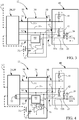
figure 1 représente un premier dispositif de mesure selon l'invention pourvu d'un capteur de courant simple avec encodage réalisé par deux résistances disposées dans ledit capteur, - la
figure 2 représente un deuxième dispositif de mesure selon l'invention pourvu d'un capteur de courant évolué sous la forme d'un intégrateur sur une boucle de Rogowski et d'un capteur de tension auxiliaire sous la forme d'une électrode de détection de tension, - la
figure 3 représente un troisième dispositif de mesure selon l'invention pourvu d'un capteur de tension auxiliaire séparé du capteur de courant, - la
figure 4 représente un quatrième dispositif de mesure selon l'invention, similaire à celui de lafigure 3 , mais comportant un sélecteur pour rendre le capteur de tension auxiliaire réversible, - la
figure 5 représente un dispositif de mesure selon l'invention raccordé à une installation électrique triphasée montrant une erreur de branchement entre les voies de tension et de courant correspondant aux phases L2 et L3, et - la
figure 6 est un diagramme des signaux de tension de l'installation triphasée de lafigure 5 et du signal de tension auxiliaire Vaux mesuré par le dispositif de mesure selon l'invention pourvu d'un module de corrélation recherchant automatiquement la voie de tension correspondant le mieux à la tension auxiliaire mesurée.
- the
figure 1 represents a first measuring device according to the invention provided with a simple current sensor with encoding produced by two resistors arranged in said sensor, - the
figure 2 represents a second measuring device according to the invention provided with an advanced current sensor in the form of an integrator on a Rogowski loop and an auxiliary voltage sensor in the form of a voltage detection electrode, - the
figure 3 represents a third measuring device according to the invention provided with an auxiliary voltage sensor separate from the current sensor, - the
figure 4 shows a fourth measuring device according to the invention, similar to that of thefigure 3 , but comprising a selector to make the auxiliary voltage sensor reversible, - the
figure 5 represents a measuring device according to the invention connected to a three-phase electrical installation showing a connection error between the voltage and current channels corresponding to the phases L2 and L3, and - the
figure 6 is a diagram of the voltage signals of the three-phase installation of thefigure 5 and of the auxiliary voltage signal Vaux measured by the measuring device according to the invention provided with a correlation module automatically searching for the voltage channel best corresponding to the measured auxiliary voltage.
En référence aux figures, le dispositif de mesure 10-13 selon l'invention comporte un capteur 20, 20' agencé pour mesurer au moins une grandeur physique d'une installation électrique et une unité de mesure 40 couplée audit capteur 20, 20' par un câble de connexion 50 particulier. Le capteur est dans l'exemple décrit et illustré un capteur de courant 20, 20' agencé pour mesurer le courant sur un des conducteurs L1 de l'installation électrique, mais peut concerner tout autre type de capteur. Le capteur de courant 20, 20' utilise des technologies existantes, telles qu'un transformateur de courant, une boucle de Rogowski, des capteurs à base de mesure champ magnétique telle que l'effet Hall ou le système « Fluxgate », ou similaire, et délivre un signal représentatif du courant mesuré, ce signal étant généralement de forme analogique. Ce capteur 20, 20' peut être aussi bien un capteur simple analogique, qu'un capteur évolué numérique. L'unité de mesure 40 est conçue pour pouvoir être connectée à tout type de capteur 20, 20' et constitue ainsi un module standard identique pour chacune des configurations illustrées dans les figures. Elle comporte notamment une unité de traitement 45, représentée uniquement sur la
Le câble de connexion 50 utilisé pour connecter le capteur de courant 20, 20' et l'unité de mesure 40 est un câble modulaire qui comporte six positions et six contacts, habituellement connu sous le nom de câble RJ12 ou tout câble similaire. Ce type de câble RJ12, également appelé Registered Jack 12, est un standard international utilisé par des appareils téléphoniques fixes. Il est également utilisé dans le domaine des réseaux locaux. Il présente trois paires de conducteurs 51, 52, 53. Une première paire de conducteurs 51 est utilisée pour la transmission différentielle d'un signal analogique représentatif d'une grandeur à mesurer provenant dudit capteur de courant 20, 20', est appelée par la suite « paire de mesure », et est raccordée à l'unité de traitement 45. Une deuxième paire de conducteurs 52 est utilisée pour l'alimentation du capteur 20, 20' par l'unité de mesure 40, et est appelée par la suite « paire d'alimentation ». Une troisième paire de conducteurs 53 est utilisée pour transmettre des informations complémentaires sous la forme de signaux DET1, DET2 indifféremment analogiques et numériques entre le capteur de courant 20, 20' et l'unité de mesure 40, est appelée par la suite « paire de communication » et est raccordée à l'unité de traitement 45. Bien entendu, tout autre système de connexion comportant au moins trois paires de conducteurs peut être utilisé.The
Les conducteurs 51+, 51- de la paire de mesure 51 sont polarisés par l'unité de mesure 40 à l'aide de deux résistances 41, 42 de forte valeur par rapport à la résistance de sortie maximale du capteur de courant 20, 20'. Une première résistance 41 est connectée entre un des conducteurs 51+ de la paire de mesure 51 et le conducteur 52+ de polarité positive de la paire d'alimentation 52, et la seconde résistance 42 est connectée entre le deuxième conducteur 51- de la paire de mesure 51 et le conducteur 52- de polarité négative de la paire d'alimentation 52. Lorsqu'aucun capteur de courant n'est raccordé à l'unité de mesure 40, la tension différentielle sur la paire de mesure 51 est quasi constante et voisine de la tension de la paire d'alimentation 52. Lorsqu'un capteur de courant 20, 20' est raccordé, et du fait de la faible impédance de sortie du capteur de courant 20, 20', la tension différentielle sur la paire de mesure 51 est l'image du signal à mesurer. Etant donné que le dispositif de mesure 10-13 est destiné à la mesure de signaux alternatifs, la mesure de la valeur moyenne de ce signal de tension différentielle permet en conséquence de détecter la présence d'un capteur de courant 20, 20'.The
La
L'unité de traitement 45 est programmable et comporte notamment une table de correspondances entre des caractéristiques d'identification et des capteur de courants 20, 20' permettant de faire la corrélation avec les signaux complémentaires DET1, DET2 qu'elle reçoit via la paire de communication 53 lui permettant de reconnaître automatiquement le type de capteur de courant 20, 20' raccordé à ladite unité de mesure 40 et donc de délivrer une valeur corrélée exploitable de la grandeur physique mesurée par ledit capteur de courant 20, 20'.Le convertisseur analogique/numérique (non représenté) intégré dans l'unité de traitement 45 fournit soit une valeur numérique permettant de déterminer le ratio de résistances 23/25 et 24/26 si le capteur 20 est analogique, soit par comparaison à un seuil avec ou sans hystérésis une séquence de valeurs binaires si le capteur 20' est numérique, comporte l'unité de traitement 60 et transmet les données d'identification sous forme de séquence de données binaires.The
La
Lorsque le capteur de courant 20' est constitué d'une boucle de Rogowski 27 associée à son intégrateur 28, comme c'est le cas dans la
La
La
Le dispositif de mesure 10-13 tel qu'il vient d'être décrit est polyvalent et doté de fonctions intelligentes. Il est notamment capable de différencier un capteur de courant simple analogique 20, dont l'encodage est effectué par de simples résistances 23 à 26, d'un capteur de courant évolué numérique 20' dont l'encodage est effectué par une unité de traitement 60. Pour ce faire, l'unité de traitement 45 prévue dans l'unité de mesure 40 est agencée pour détecter une activité, par la présence d'un signal binaire DET1, sur le conducteur 53a de la paire de communication 53 supportant éventuellement la transmission numérique dans le cas d'un capteur de courant évolué numérique 20'. Si au bout d'un certain temps, elle ne détecte aucune activité cohérente sur ce conducteur 53a, elle tente d'identifier un capteur de courant simple analogique 20 en fonction des niveaux moyens de tension détectés entre le conducteur 53a de la paire de communication 53 et le conducteur 52- de polarité négative de la paire d'alimentation 52. Si elle ne peut pas mettre en correspondance un capteur de courant simple analogique 20 avec les niveaux moyens de tension détectés, elle relance une recherche d'un capteur de courant évolué numérique 20'.The measuring device 10-13 as just described is versatile and has intelligent functions. It is in particular capable of differentiating a simple analog
Lorsque le dispositif de mesure 11-13 comporte un capteur de courant 20' évolué numérique, par exemple selon la
Il est également possible d'utiliser le conducteur 53b de la paire de communication 53 pour véhiculer un signal complémentaire DET2 correspondant à une grandeur physique additionnelle ou auxiliaire de l'installation électrique et se présentant par exemple sous une forme analogique. Comme on l'a vu en référence aux
L'unité de traitement 45 de l'unité de mesure 40 peut comporter un module de corrélation permettant de détecter automatiquement quelle est la voie de tension qui correspond au capteur de courant 20' pourvu d'un capteur de tension auxiliaire 30, en recherchant laquelle des tensions nominales V1, V2, V3 connectées à l'unité de traitement 45 présente le maximum de corrélation avec le signal de tension auxiliaire Vaux. La
Dans cette configuration, le signal auxiliaire Vaux, image de la tension sur un des conducteurs L1 sur lequel on mesure l'intensité, peut également être utilisé pour détecter l'ouverture d'un organe de coupure (tel qu'un disjoncteur) ou la fusion d'un fusible pour déclencher une alerte ou similaire, si les capteurs de tension 30' alimentant les voies de tension V1, V2, V3 de l'unité de traitement 45 sont connectés aux phases L1, L2, L3 en amont du dispositif de coupure et si les capteurs de courant 20' comportant un capteur de tension auxiliaire 30 sont connectés en aval dudit dispositif de coupure.In this configuration, the auxiliary signal Vaux, image of the voltage on one of the conductors L1 on which the intensity is measured, can also be used to detect the opening of a breaking device (such as a circuit breaker) or the blowing of a fuse to trigger an alert or the like, if the voltage sensors 30 'supplying the voltage channels V1, V2, V3 of the
Le dispositif de mesure 10-13 selon l'invention utilise des composants électriques et électroniques disponibles sur le marché. Il est rendu intelligent grâce à l'intégration d'unités de traitement 45, 60 programmables et à une communication indifféremment analogique et numérique entre les capteurs de courant 20, 20' et l'unité de mesure 40 qui constitue un module standardisé. De ce fait, le dispositif de mesure 10-13 est modulaire, polyvalent et s'adapte à tout type de capteurs de courant 20, 20' de manière automatique, et de la même manière à tout autre type de capteurs équivalents. Cette conception ouvre de nouvelles perspectives d'exploitation des grandeurs physiques d'une installation électrique et permet ainsi des applications multiples tendant vers une plus grande sécurité et une meilleure fiabilité des données mesurées.The measuring device 10-13 according to the invention uses electrical and electronic components available on the market. It is made intelligent thanks to the integration of
A titre d'exemple, dans le cadre d'une application de comptage d'énergie, l'utilisation du dispositif de mesure 10-13 selon l'invention rend la fraude particulièrement délicate. En effet, ce dispositif de mesure 10-13 est capable de détecter l'absence d'un capteur de courant grâce aux résistances 41, 42 prévues dans l'unité de mesure 40, le calibre nominal d'un capteur de courant, le remplacement d'un capteur de courant en contrôlant le numéro de série, les incohérences entre les tensions mesurées directement par le dispositif de mesure 40 connecté au(x) capteur de courant(s) 20, 20', ledit dispositif de mesure 40 étant en fait un compteur d'énergie, et celles détectées par le capteur de tension auxiliaire 30, etc.For example, in the context of an energy metering application, the use of the measuring device 10-13 according to the invention makes fraud particularly delicate. Indeed, this measurement device 10-13 is capable of detecting the absence of a current sensor thanks to the
De même, l'exploitation d'un signal auxiliaire peut permettre également d'améliorer la fiabilité de la recherche de défauts à la terre dans les installations électriques isolées de la terre. Dans ce cas, le capteur de courant comporte un capteur de courant de fuite à la terre. Le signal utile pour mesurer les défauts résistifs à la terre est en général un signal de courant à très basse fréquence, de faible amplitude, qui est souvent superposé à un signal de courant présent sur le conducteur à la fréquence du réseau, d'amplitude beaucoup plus élevée. Pour pouvoir traiter correctement le signal utile à très basse fréquence, on effectue un filtrage passe-bas du signal global afin de pouvoir correctement amplifier le signal de courant à très basse fréquence. Cependant, le signal de courant de fuite à la terre de l'installation à contrôler peut présenter une composante à la fréquence du réseau (50Hz par exemple) qui peut être d'amplitude beaucoup plus forte que la composante à basse fréquence transmise sur la paire de mesure 51. Cette composante à la fréquence du réseau peut fournir des informations intéressantes, en particulier pour vérifier l'absence de saturation du capteur de courant de fuite à la terre et que le capteur de courant de fuite à la terre est bien utilisé dans une gamme de courant compatible avec l'application de recherche de défauts résistifs à la terre. Le conducteur 53b de la paire de communication 53 peut donc être utilisé pour fournir l'image non filtrée du courant de fuite à la terre et pour déclencher le cas échéant une alerte.Likewise, the use of an auxiliary signal can also make it possible to improve the reliability of the search for earth faults in electrical installations isolated from earth. In this case, the current sensor includes an earth leakage current sensor. The signal useful for measuring resistive earth faults is generally a very low frequency current signal, of small amplitude, which is often superimposed on a current signal present on the conductor at the network frequency, of much higher amplitude. To be able to correctly process the useful signal at very low frequency, a low-pass filtering of the overall signal is carried out in order to be able to correctly amplify the current signal at very low frequency. However, the earth leakage current signal of the installation to be checked may have a component at the network frequency (50Hz for example) which can be of much greater amplitude than the low frequency component transmitted on the pair. 51. This component at the network frequency can provide interesting information, in particular to check the absence of saturation of the earth leakage current sensor and that the earth leakage current sensor is well used in a current range compatible with the earth fault resistive fault finding application. The
Un autre exemple d'exploitation d'un signal auxiliaire peut être un signal fournissant une information sur la même grandeur physique que celle déjà mesurée, par exemple un signal de courant, mais obtenu de manière différente et moins précise par un capteur de courant additionnel bon marché. La comparaison des deux signaux représentatifs d'une même grandeur physique peut permettre de détecter une défaillance du capteur de courant 20, 20' principal et trouve donc sa place dans des dispositifs de mesure 10-13 pour lesquels la sécurité de fonctionnement est un critère important.Another example of using an auxiliary signal can be a signal providing information on the same physical quantity as that already measured, for example a current signal, but obtained in a different and less precise manner by a good additional current sensor. market. The comparison of two signals representative of the same physical quantity can make it possible to detect a failure of the main
Ces différents exemples de réalisation montrent parfaitement bien la grande flexibilité d'utilisation de ce dispositif de mesure 10-13 ainsi que ses possibilités d'exploitation grâce notamment au câble de connexion 50 reliant les capteurs de courant 20, 20' et le capteur de tension auxiliaire 30 à l'unité de mesure 40 permettant de véhiculer des informations autres que les valeurs des grandeurs mesurées par lesdits capteurs, ces autres informations pouvant être infinies et utilisées pour assurer de multiples fonctions telles que la détection d'anomalie, de fraude et/ou de coupure, le contrôle, la surveillance, la sécurité, etc.These different exemplary embodiments perfectly show the great flexibility of use of this measuring device 10-13 as well as its possibilities of operation thanks in particular to the
La présente invention n'est pas limitée aux exemples de réalisation décrits mais s'étend à toute modification et variante évidentes pour un homme du métier tout en restant dans l'étendue de la protection définie dans les revendications annexées.The present invention is not limited to the embodiments described but extends to any modification and variant obvious to a person skilled in the art while remaining within the scope of the protection defined in the appended claims.
Claims (18)
- Device (10-13) for measuring at least one physical quantity of an electric installation, comprising at least one sensor (20, 20') arranged to measure at least the said physical quantity and to deliver at least one signal representative of the said physical quantity, and at least one measuring unit (40) arranged to receive the said signal and process it to deliver at least one usable measured value, the said sensor and the said measuring unit being connected to each other by at least one connecting cable (50), the said connecting cable (50) comprising at least three conductor pairs, a first conductor pair (51+, 51-), called measuring pair (51), arranged to transmit said signal representative of the said physical quantity measured by the said sensor (20, 20'), a second pair of conductors (52+, 52-), called power supply pair (52), arranged to supply power to the said sensor (20), 20') by the said measuring unit (40), and a third pair of conductors (53a, 53b), called communication pair (53), arranged to transmit at least one complementary signal (DET1, DET2) between the said sensor (20, 20') and the said measuring unit (40), the said sensor (20, 20') comprising encoding means (23, 24; 60) arranged to characterize the said sensor and transmit to the said measuring unit (40) via the said communication pair (53) at least one complementary signal (DET1, DET2) corresponding to at least one identification characteristic of the said sensor, the said measuring unit (40) comprising in addition encoding means (25, 26) complementary to the encoding means (23, 24, 60) provided in the said sensor (20, 20'),
characterized in that the said measuring unit (10-13) is modular and adaptable both to a simple analog sensor (20) and to an advanced digital sensor (20'), in that said measuring unit (40) is designed to be connectable to any type of sensor (20, 20') and constitutes a standard module, and in that the said measuring unit (40) further comprises a processing unit (45) incorporating an analog/digital converter connected to said communication pair (53) for receiving and processing said at least one complementary signal (DET1, DET2) transmitted on at least one of the conductors (53a, 53b) of said communication pair (53), this signal being indifferently an analog signal or a digital signal and being representative of at least one identification characteristic of said sensor allowing said measuring unit (40) to automatically recognize the sensor (20, 20') between a simple analog sensor (20) and an advanced digital sensor (20') which is connected to said measuring unit (40), and to deliver a correlated usable value of said measured physical quantity. - Measuring device according to claim 1, characterized in that said sensor (20) is analog and comprises two resistors (23, 24) whose resistance values are chosen as a function of at least one identification characteristic of said sensor, and in that the encoding means of said measuring unit (40) comprises two other resistors (25, 26) arranged to form with the two resistors (23, 24) of said sensor (20), two voltage divider bridges connected on the one hand to said supply pair (52) and on the other hand to said communication pair (53) in order to deliver at the terminals of said communication pair (53) to the processing unit (45) of said measuring unit (40) at least one complementary voltage signal (DET1, DET2) in analog form representative of said identification characteristic of said sensor (20).
- Measuring device according to claim 1, characterized in that said sensor (20') is digital and comprises a processing unit (60) in which at least one identification characteristic of said sensor (20') is recorded, said processing unit being connected on the one hand to said power supply pair (52) and on the other hand to at least one of the conductors (53a) of the communication pair (53) in order to deliver to the processing unit (45) of said measuring unit (40) at least one additional signal (DET1, DET2) in digital form representative of said identification characteristic of said sensor (20').
- Measuring device according to any one of the preceding claims, characterized in that said encoding means (23, 24; 60) of said sensors (20, 20') are arranged to transmit to the processing unit (45) of said measuring unit (40) via said communication pair (53) a plurality of complementary signals (DET1, DET2) corresponding to a plurality of identification characteristics of said sensor enabling said measuring unit (40) to recognize said sensor (20, 20') between a single analog sensor (20) and an advanced digital sensor (20'), said identification characteristics of said sensor (20, 20') being selected from the group comprising the nominal voltage of the sensor, the nominal current of the sensor, the calibration data of the sensor, the compensation curve for the gain errors of the sensor, the compensation curve for the phase errors of the sensor.
- Measuring device according to claim 1, characterized in that said measuring unit (40) comprises two resistors (41, 42) connected respectively between the conductors (51+, 52+; 51-, 52-) of said measuring (51) and supply (52) pairs for polarizing the conductors (51+, 51-) of said measuring pair (51) and detecting the presence of said sensor (20, 20').
- Measuring device according to claim 1, characterized in that said communication pair (53) is arranged to carry on one of its conductors (53a) at least one first complementary signal (DET1) representing at least one identification characteristic of said sensor (20, 20') and on the other of its conductors (53b) at least one second complementary signal (DET2) corresponding to an auxiliary physical quantity of said electrical installation.
- Measuring device according to any of the preceding claims, characterized in that said sensor (20, 20') is a current sensor arranged to measure the current on one of the conductors (L1) of said electrical installation.
- Measuring device according to claim 7, characterized in that it comprises at least one auxiliary voltage sensor (30) arranged to measure an auxiliary voltage value representing the voltage present on the conductor (LI) whose current is measured by said current sensor (20, 20'), this auxiliary voltage value forming an auxiliary physical quantity carried on one of the conductors (53b) of said communication pair (53).
- Measuring device according to claim 8, characterized in that said auxiliary voltage sensor (30) is integrated with said current sensor (20, 20').
- Measuring device according to claim 8, characterized in that said auxiliary voltage sensor (30) is connected in series between said current sensor (20, 20') and said measuring unit (40) and connected to each of them by at least one connecting cable (50).
- Measuring device according to claim 10, characterized in that said auxiliary voltage sensor (30) comprises at least one selector (70) arranged to automatically reverse the direction of connection of said auxiliary voltage sensor (30) between said current sensor (20, 20') and said measuring unit (40) in the event of a connection error.
- Measuring device according to claim 7, characterized in that said current sensor (20, 20') comprises at least one earth leakage current sensor with a very low frequency relative to the frequency of the network supplying said electrical installation, arranged to measure an earth leakage current value with a bandwidth including at least the frequency of the supply network, this earth leakage current value forming an auxiliary physical quantity conveyed on one of the conductors (53b) of said communication pair (53).
- Measuring device according to claim 7, characterized in that said current sensor (20, 20') comprises at least one temperature sensor arranged to measure the temperature of said current sensor, this temperature forming an auxiliary physical quantity carried on one of the conductors (53b) of said communication pair (53).
- Measuring device according to claim 7, characterized in that said current sensor (20, 20') comprises at least one additional current sensor arranged to carry out a second current measurement on the conductor (L1) of said electrical installation, this second current measurement forming a physical quantity conveyed on one of the conductors (53b) of said communication pair (53) in order to check the correct operation of said current sensor (20, 20') by comparing this second current measurement with that carried out by said current sensor (20, 20').
- Measuring device according to claim 1, characterized in that said processing unit (45) provided in the measuring unit (40) comprises at least one table of correspondences between identification characteristics and sensors (20, 20').
- Measuring device according to claim 8, characterized in that it comprises N current sensors (20, 20'), each provided with an auxiliary voltage sensor (30), and N voltage sensors (30') arranged to measure respectively the current and the voltage on N conductors (L1, L2, L3) of said electrical installation, and in that said measuring unit (40) comprises a correlation module arranged to correlate the voltage measurement (V1, V2, V3) corresponding to the measurement of the auxiliary voltage (Vaux1, Vaux2, Vaux3) carried out on the same conductor (L1, L2, L3) of said electrical installation and to automatically compensate for possible connection errors of said sensors (20, 20', 30').
- Use of the measuring device (10-13) according to any of the preceding claims for detecting an attempt of fraud on said measuring device (10-13) by detecting an inconsistency in the signals transmitted via said connecting cable (50) between said sensor (20, 20') and said measuring unit (40).
- Use of the measuring device (10-13) according to claim 16 for detecting the opening of a disconnection device arranged upstream of an electrical installation if, on the one hand, the voltage sensor (30') is connected upstream of the disconnection device and if, on the other hand, the current sensor (20') provided with its auxiliary voltage sensor (30) is connected downstream of the disconnection device.
Applications Claiming Priority (2)
| Application Number | Priority Date | Filing Date | Title |
|---|---|---|---|
| FR1452853A FR3019303B1 (en) | 2014-04-01 | 2014-04-01 | DEVICE FOR MEASURING AT LEAST ONE PHYSICAL SIZE OF AN ELECTRICAL INSTALLATION |
| PCT/FR2015/050793 WO2015150671A1 (en) | 2014-04-01 | 2015-03-27 | Device for measuring at least one physical quantity of an electric installation |
Publications (2)
| Publication Number | Publication Date |
|---|---|
| EP3126783A1 EP3126783A1 (en) | 2017-02-08 |
| EP3126783B1 true EP3126783B1 (en) | 2020-05-06 |
Family
ID=50829188
Family Applications (1)
| Application Number | Title | Priority Date | Filing Date |
|---|---|---|---|
| EP15719789.8A Active EP3126783B1 (en) | 2014-04-01 | 2015-03-27 | Device for measuring at least one physical quantity of an electric installation |
Country Status (5)
| Country | Link |
|---|---|
| US (1) | US9857396B2 (en) |
| EP (1) | EP3126783B1 (en) |
| CN (1) | CN106133533B (en) |
| FR (1) | FR3019303B1 (en) |
| WO (1) | WO2015150671A1 (en) |
Families Citing this family (18)
| Publication number | Priority date | Publication date | Assignee | Title |
|---|---|---|---|---|
| US9949692B2 (en) | 2012-12-21 | 2018-04-24 | Canary Medical Inc. | Stent graft monitoring assembly and method of use thereof |
| WO2015200718A1 (en) | 2014-06-25 | 2015-12-30 | Hunter William L | Devices, systems and methods for using and monitoring tubes in body passageways |
| WO2015200722A2 (en) | 2014-06-25 | 2015-12-30 | Parker, David, W. | Devices, systems and methods for using and monitoring orthopedic hardware |
| CA2998709A1 (en) | 2014-09-17 | 2016-03-24 | Canary Medical Inc. | Devices, systems and methods for using and monitoring medical devices |
| FR3033647B1 (en) | 2015-03-10 | 2019-07-26 | Socomec | CURRENT SENSOR FOR MEASURING ALTERNATING CURRENT |
| US11497964B1 (en) | 2015-09-17 | 2022-11-15 | Canary Medical Switzerland Ag | Devices, systems and methods for using and monitoring sports equipment and sports activities |
| US11042916B1 (en) | 2016-02-29 | 2021-06-22 | Canary Medical Inc. | Computer-based marketplace for information |
| US11191479B2 (en) | 2016-03-23 | 2021-12-07 | Canary Medical Inc. | Implantable reporting processor for an alert implant |
| AU2017237099B2 (en) | 2016-03-23 | 2022-05-26 | Canary Medical Inc. | Implantable reporting processor for an alert implant |
| US10178178B2 (en) * | 2016-09-21 | 2019-01-08 | Semiconductor Components Industries, Llc | Low power sensor communication using two or fewer wires |
| FR3074914B1 (en) | 2017-12-07 | 2019-11-29 | Socomec | METHOD FOR DETECTING THE CONDITION OF AN ELECTRICAL PROTECTION DEVICE IN AN ELECTRICAL INSTALLATION AND DETECTION DEVICE IMPLEMENTING SAID METHOD |
| DE102018204129B3 (en) * | 2018-03-19 | 2019-07-04 | Siemens Aktiengesellschaft | Method and device for measuring an alternating current with a Rogowski current transformer |
| US10381995B1 (en) * | 2018-07-19 | 2019-08-13 | Nxp B.V. | Vehicle radio interference sensor device |
| EP4152539B1 (en) * | 2018-09-27 | 2024-05-15 | Siemens Aktiengesellschaft | Arrangement and method for a low voltage alternating current circuit |
| CN111856310B (en) * | 2019-04-03 | 2023-08-29 | 深圳富联富桂精密工业有限公司 | Power Distribution Unit Monitoring System |
| CN112213634B (en) * | 2020-10-26 | 2023-05-09 | 浙江天正电气股份有限公司 | Method and device for detecting running state of circuit breaker |
| DE102021201810A1 (en) * | 2021-02-25 | 2022-08-25 | Siemens Aktiengesellschaft | Low-voltage circuit breaker and power measurement arrangement |
| CN113078676B (en) * | 2021-04-02 | 2023-04-18 | 新风光电子科技股份有限公司 | Control method of current sensor direction and current loop decoupling direction interlocking mechanism |
Family Cites Families (10)
| Publication number | Priority date | Publication date | Assignee | Title |
|---|---|---|---|---|
| DE3743846A1 (en) * | 1987-12-23 | 1989-07-13 | Porsche Ag | TRANSDUCERS |
| FR2629465B1 (en) | 1988-03-30 | 1992-02-21 | Norsolor Sa | FLEXIBLE THERMOPLASTIC COMPOSITIONS BASED ON ETHYLENE COPOLYMER AND SATURED POLYESTER AND ARTICLES CONTAINING THEM |
| US5218298A (en) * | 1992-03-02 | 1993-06-08 | Allegro Microsystems Inc. | Two-terminal-hall-sensors monitoring system for providing decoded magnetic field amplitude signals and system diagnostic signals |
| US5839094A (en) * | 1995-06-30 | 1998-11-17 | Ada Technologies, Inc. | Portable data collection device with self identifying probe |
| EP1471359A4 (en) * | 2002-01-30 | 2010-08-11 | Bridgestone Corp | Measured value output device, measured value monitor, current value output device, and current monitor |
| US7373356B2 (en) * | 2002-08-14 | 2008-05-13 | National Instruments Corporation | Transducer specification database |
| KR101075018B1 (en) * | 2009-12-28 | 2011-10-19 | 전자부품연구원 | Apparatus of processing sensor data for vehicle using eXtensible Markup Language (XML), and method for the same |
| US8442787B2 (en) * | 2010-04-30 | 2013-05-14 | Infineon Technologies Ag | Apparatus, sensor circuit, and method for operating an apparatus or a sensor circuit |
| US8736468B2 (en) * | 2011-12-16 | 2014-05-27 | Lear Corporation | Method and system for monitoring for variation of converter voltage reference |
| US8866627B2 (en) * | 2012-07-20 | 2014-10-21 | Eaton Corporation | Method and apparatus of identifying or locating current sensors |
-
2014
- 2014-04-01 FR FR1452853A patent/FR3019303B1/en active Active
-
2015
- 2015-03-27 US US15/125,250 patent/US9857396B2/en active Active
- 2015-03-27 CN CN201580016559.6A patent/CN106133533B/en active Active
- 2015-03-27 WO PCT/FR2015/050793 patent/WO2015150671A1/en active Application Filing
- 2015-03-27 EP EP15719789.8A patent/EP3126783B1/en active Active
Non-Patent Citations (1)
| Title |
|---|
| None * |
Also Published As
| Publication number | Publication date |
|---|---|
| FR3019303B1 (en) | 2019-06-14 |
| US20170138986A1 (en) | 2017-05-18 |
| CN106133533A (en) | 2016-11-16 |
| WO2015150671A1 (en) | 2015-10-08 |
| EP3126783A1 (en) | 2017-02-08 |
| US9857396B2 (en) | 2018-01-02 |
| FR3019303A1 (en) | 2015-10-02 |
| CN106133533B (en) | 2019-04-16 |
Similar Documents
| Publication | Publication Date | Title |
|---|---|---|
| EP3126783B1 (en) | Device for measuring at least one physical quantity of an electric installation | |
| EP2648008B1 (en) | Insulation monitoring system for secured electric power system | |
| EP2169799B1 (en) | Directional detection of a ground fault | |
| EP0518785B1 (en) | Device for checking and measuring the insulation of a power line having an insulated neutral conductor | |
| EP3126854B1 (en) | Method of measuring the energy consumption of the branches of an electrical network and measurement equipment implementing said method | |
| CA2315896C (en) | Electronic circuit for monitoring voltage variation | |
| WO2019110711A1 (en) | Method for detecting the state of an electronic protective appliance in an electrical facility and detection device implementing said method | |
| EP3361268B1 (en) | Monitoring circuit of an electrical power network | |
| EP0537066B1 (en) | Method for the selective detection of resistive defects in power-distribution networks | |
| EP2910958A1 (en) | Detecting a fault, in particular a transient fault, in an electrical network | |
| FR2996311A1 (en) | METHOD AND DEVICE FOR DETERMINING THE CHARACTERISTICS OF AN ISOLATION FAULT | |
| FR2672744A1 (en) | SELECTIVE AND AUTOMATIC ELECTRIC SECURITY DEVICE. | |
| EP2954339B1 (en) | Device for signal processing in an electrical installation | |
| US11493546B2 (en) | Connection test device and method for checking an intermittent impedance variation | |
| WO2018158511A1 (en) | Redundant and dissimilar system for monitoring the status of control contactors of an aircraft control stick | |
| FR3029294B1 (en) | METHOD FOR DETECTING AN INCOHERENCE BETWEEN A CONTROLLED STATE AND A REAL STATE OF A CUTTING MEMBER | |
| EP4300112A1 (en) | Detection of loss of neutral | |
| FR2761154A1 (en) | INSTALLATION FOR DETECTING AND LOCATING LIQUID LEAKS | |
| FR2747198A1 (en) | Device for detection of serial faults in electric installations | |
| FR2827676A1 (en) | Power stage diagnostic system uses supply divider and two processor inputs | |
| EP3015873A1 (en) | Method for detecting a fraudulent attempt to bypass a meter | |
| FR2761160A1 (en) | Actuator sensor interface bus defect detector | |
| FR2873449A1 (en) | METHOD FOR DETECTING DEFECTS ON INTERNAL CONNECTIONS OF AN INTEGRATED CIRCUIT AND CORRESPONDING DEVICE |
Legal Events
| Date | Code | Title | Description |
|---|---|---|---|
| STAA | Information on the status of an ep patent application or granted ep patent |
Free format text: STATUS: THE INTERNATIONAL PUBLICATION HAS BEEN MADE |
|
| PUAI | Public reference made under article 153(3) epc to a published international application that has entered the european phase |
Free format text: ORIGINAL CODE: 0009012 |
|
| STAA | Information on the status of an ep patent application or granted ep patent |
Free format text: STATUS: REQUEST FOR EXAMINATION WAS MADE |
|
| 17P | Request for examination filed |
Effective date: 20161006 |
|
| AK | Designated contracting states |
Kind code of ref document: A1 Designated state(s): AL AT BE BG CH CY CZ DE DK EE ES FI FR GB GR HR HU IE IS IT LI LT LU LV MC MK MT NL NO PL PT RO RS SE SI SK SM TR |
|
| AX | Request for extension of the european patent |
Extension state: BA ME |
|
| DAV | Request for validation of the european patent (deleted) | ||
| DAX | Request for extension of the european patent (deleted) | ||
| GRAP | Despatch of communication of intention to grant a patent |
Free format text: ORIGINAL CODE: EPIDOSNIGR1 |
|
| STAA | Information on the status of an ep patent application or granted ep patent |
Free format text: STATUS: GRANT OF PATENT IS INTENDED |
|
| INTG | Intention to grant announced |
Effective date: 20190911 |
|
| GRAS | Grant fee paid |
Free format text: ORIGINAL CODE: EPIDOSNIGR3 |
|
| GRAJ | Information related to disapproval of communication of intention to grant by the applicant or resumption of examination proceedings by the epo deleted |
Free format text: ORIGINAL CODE: EPIDOSDIGR1 |
|
| GRAL | Information related to payment of fee for publishing/printing deleted |
Free format text: ORIGINAL CODE: EPIDOSDIGR3 |
|
| STAA | Information on the status of an ep patent application or granted ep patent |
Free format text: STATUS: REQUEST FOR EXAMINATION WAS MADE |
|
| GRAP | Despatch of communication of intention to grant a patent |
Free format text: ORIGINAL CODE: EPIDOSNIGR1 |
|
| STAA | Information on the status of an ep patent application or granted ep patent |
Free format text: STATUS: GRANT OF PATENT IS INTENDED |
|
| INTC | Intention to grant announced (deleted) | ||
| INTG | Intention to grant announced |
Effective date: 20200131 |
|
| GRAA | (expected) grant |
Free format text: ORIGINAL CODE: 0009210 |
|
| STAA | Information on the status of an ep patent application or granted ep patent |
Free format text: STATUS: THE PATENT HAS BEEN GRANTED |
|
| AK | Designated contracting states |
Kind code of ref document: B1 Designated state(s): AL AT BE BG CH CY CZ DE DK EE ES FI FR GB GR HR HU IE IS IT LI LT LU LV MC MK MT NL NO PL PT RO RS SE SI SK SM TR |
|
| REG | Reference to a national code |
Ref country code: GB Ref legal event code: FG4D Free format text: NOT ENGLISH |
|
| REG | Reference to a national code |
Ref country code: CH Ref legal event code: EP Ref country code: AT Ref legal event code: REF Ref document number: 1267488 Country of ref document: AT Kind code of ref document: T Effective date: 20200515 |
|
| REG | Reference to a national code |
Ref country code: IE Ref legal event code: FG4D Free format text: LANGUAGE OF EP DOCUMENT: FRENCH |
|
| REG | Reference to a national code |
Ref country code: DE Ref legal event code: R096 Ref document number: 602015052171 Country of ref document: DE |
|
| REG | Reference to a national code |
Ref country code: LT Ref legal event code: MG4D |
|
| REG | Reference to a national code |
Ref country code: NL Ref legal event code: MP Effective date: 20200506 |
|
| PG25 | Lapsed in a contracting state [announced via postgrant information from national office to epo] |
Ref country code: PT Free format text: LAPSE BECAUSE OF FAILURE TO SUBMIT A TRANSLATION OF THE DESCRIPTION OR TO PAY THE FEE WITHIN THE PRESCRIBED TIME-LIMIT Effective date: 20200907 Ref country code: IS Free format text: LAPSE BECAUSE OF FAILURE TO SUBMIT A TRANSLATION OF THE DESCRIPTION OR TO PAY THE FEE WITHIN THE PRESCRIBED TIME-LIMIT Effective date: 20200906 Ref country code: LT Free format text: LAPSE BECAUSE OF FAILURE TO SUBMIT A TRANSLATION OF THE DESCRIPTION OR TO PAY THE FEE WITHIN THE PRESCRIBED TIME-LIMIT Effective date: 20200506 Ref country code: SE Free format text: LAPSE BECAUSE OF FAILURE TO SUBMIT A TRANSLATION OF THE DESCRIPTION OR TO PAY THE FEE WITHIN THE PRESCRIBED TIME-LIMIT Effective date: 20200506 Ref country code: GR Free format text: LAPSE BECAUSE OF FAILURE TO SUBMIT A TRANSLATION OF THE DESCRIPTION OR TO PAY THE FEE WITHIN THE PRESCRIBED TIME-LIMIT Effective date: 20200807 Ref country code: FI Free format text: LAPSE BECAUSE OF FAILURE TO SUBMIT A TRANSLATION OF THE DESCRIPTION OR TO PAY THE FEE WITHIN THE PRESCRIBED TIME-LIMIT Effective date: 20200506 Ref country code: NO Free format text: LAPSE BECAUSE OF FAILURE TO SUBMIT A TRANSLATION OF THE DESCRIPTION OR TO PAY THE FEE WITHIN THE PRESCRIBED TIME-LIMIT Effective date: 20200806 |
|
| PG25 | Lapsed in a contracting state [announced via postgrant information from national office to epo] |
Ref country code: LV Free format text: LAPSE BECAUSE OF FAILURE TO SUBMIT A TRANSLATION OF THE DESCRIPTION OR TO PAY THE FEE WITHIN THE PRESCRIBED TIME-LIMIT Effective date: 20200506 Ref country code: HR Free format text: LAPSE BECAUSE OF FAILURE TO SUBMIT A TRANSLATION OF THE DESCRIPTION OR TO PAY THE FEE WITHIN THE PRESCRIBED TIME-LIMIT Effective date: 20200506 Ref country code: BG Free format text: LAPSE BECAUSE OF FAILURE TO SUBMIT A TRANSLATION OF THE DESCRIPTION OR TO PAY THE FEE WITHIN THE PRESCRIBED TIME-LIMIT Effective date: 20200806 Ref country code: RS Free format text: LAPSE BECAUSE OF FAILURE TO SUBMIT A TRANSLATION OF THE DESCRIPTION OR TO PAY THE FEE WITHIN THE PRESCRIBED TIME-LIMIT Effective date: 20200506 |
|
| REG | Reference to a national code |
Ref country code: AT Ref legal event code: MK05 Ref document number: 1267488 Country of ref document: AT Kind code of ref document: T Effective date: 20200506 |
|
| PG25 | Lapsed in a contracting state [announced via postgrant information from national office to epo] |
Ref country code: AL Free format text: LAPSE BECAUSE OF FAILURE TO SUBMIT A TRANSLATION OF THE DESCRIPTION OR TO PAY THE FEE WITHIN THE PRESCRIBED TIME-LIMIT Effective date: 20200506 Ref country code: NL Free format text: LAPSE BECAUSE OF FAILURE TO SUBMIT A TRANSLATION OF THE DESCRIPTION OR TO PAY THE FEE WITHIN THE PRESCRIBED TIME-LIMIT Effective date: 20200506 |
|
| PG25 | Lapsed in a contracting state [announced via postgrant information from national office to epo] |
Ref country code: EE Free format text: LAPSE BECAUSE OF FAILURE TO SUBMIT A TRANSLATION OF THE DESCRIPTION OR TO PAY THE FEE WITHIN THE PRESCRIBED TIME-LIMIT Effective date: 20200506 Ref country code: AT Free format text: LAPSE BECAUSE OF FAILURE TO SUBMIT A TRANSLATION OF THE DESCRIPTION OR TO PAY THE FEE WITHIN THE PRESCRIBED TIME-LIMIT Effective date: 20200506 Ref country code: SM Free format text: LAPSE BECAUSE OF FAILURE TO SUBMIT A TRANSLATION OF THE DESCRIPTION OR TO PAY THE FEE WITHIN THE PRESCRIBED TIME-LIMIT Effective date: 20200506 Ref country code: ES Free format text: LAPSE BECAUSE OF FAILURE TO SUBMIT A TRANSLATION OF THE DESCRIPTION OR TO PAY THE FEE WITHIN THE PRESCRIBED TIME-LIMIT Effective date: 20200506 Ref country code: CZ Free format text: LAPSE BECAUSE OF FAILURE TO SUBMIT A TRANSLATION OF THE DESCRIPTION OR TO PAY THE FEE WITHIN THE PRESCRIBED TIME-LIMIT Effective date: 20200506 Ref country code: RO Free format text: LAPSE BECAUSE OF FAILURE TO SUBMIT A TRANSLATION OF THE DESCRIPTION OR TO PAY THE FEE WITHIN THE PRESCRIBED TIME-LIMIT Effective date: 20200506 Ref country code: DK Free format text: LAPSE BECAUSE OF FAILURE TO SUBMIT A TRANSLATION OF THE DESCRIPTION OR TO PAY THE FEE WITHIN THE PRESCRIBED TIME-LIMIT Effective date: 20200506 |
|
| REG | Reference to a national code |
Ref country code: DE Ref legal event code: R097 Ref document number: 602015052171 Country of ref document: DE |
|
| PG25 | Lapsed in a contracting state [announced via postgrant information from national office to epo] |
Ref country code: SK Free format text: LAPSE BECAUSE OF FAILURE TO SUBMIT A TRANSLATION OF THE DESCRIPTION OR TO PAY THE FEE WITHIN THE PRESCRIBED TIME-LIMIT Effective date: 20200506 Ref country code: PL Free format text: LAPSE BECAUSE OF FAILURE TO SUBMIT A TRANSLATION OF THE DESCRIPTION OR TO PAY THE FEE WITHIN THE PRESCRIBED TIME-LIMIT Effective date: 20200506 |
|
| PLBE | No opposition filed within time limit |
Free format text: ORIGINAL CODE: 0009261 |
|
| STAA | Information on the status of an ep patent application or granted ep patent |
Free format text: STATUS: NO OPPOSITION FILED WITHIN TIME LIMIT |
|
| 26N | No opposition filed |
Effective date: 20210209 |
|
| PG25 | Lapsed in a contracting state [announced via postgrant information from national office to epo] |
Ref country code: SI Free format text: LAPSE BECAUSE OF FAILURE TO SUBMIT A TRANSLATION OF THE DESCRIPTION OR TO PAY THE FEE WITHIN THE PRESCRIBED TIME-LIMIT Effective date: 20200506 |
|
| PG25 | Lapsed in a contracting state [announced via postgrant information from national office to epo] |
Ref country code: MC Free format text: LAPSE BECAUSE OF FAILURE TO SUBMIT A TRANSLATION OF THE DESCRIPTION OR TO PAY THE FEE WITHIN THE PRESCRIBED TIME-LIMIT Effective date: 20200506 |
|
| REG | Reference to a national code |
Ref country code: CH Ref legal event code: PL |
|
| REG | Reference to a national code |
Ref country code: BE Ref legal event code: MM Effective date: 20210331 |
|
| PG25 | Lapsed in a contracting state [announced via postgrant information from national office to epo] |
Ref country code: IE Free format text: LAPSE BECAUSE OF NON-PAYMENT OF DUE FEES Effective date: 20210327 Ref country code: LI Free format text: LAPSE BECAUSE OF NON-PAYMENT OF DUE FEES Effective date: 20210331 Ref country code: LU Free format text: LAPSE BECAUSE OF NON-PAYMENT OF DUE FEES Effective date: 20210327 Ref country code: CH Free format text: LAPSE BECAUSE OF NON-PAYMENT OF DUE FEES Effective date: 20210331 |
|
| PG25 | Lapsed in a contracting state [announced via postgrant information from national office to epo] |
Ref country code: BE Free format text: LAPSE BECAUSE OF NON-PAYMENT OF DUE FEES Effective date: 20210331 |
|
| PGFP | Annual fee paid to national office [announced via postgrant information from national office to epo] |
Ref country code: FR Payment date: 20230324 Year of fee payment: 9 |
|
| PG25 | Lapsed in a contracting state [announced via postgrant information from national office to epo] |
Ref country code: HU Free format text: LAPSE BECAUSE OF FAILURE TO SUBMIT A TRANSLATION OF THE DESCRIPTION OR TO PAY THE FEE WITHIN THE PRESCRIBED TIME-LIMIT; INVALID AB INITIO Effective date: 20150327 |
|
| PGFP | Annual fee paid to national office [announced via postgrant information from national office to epo] |
Ref country code: IT Payment date: 20230309 Year of fee payment: 9 |
|
| PG25 | Lapsed in a contracting state [announced via postgrant information from national office to epo] |
Ref country code: CY Free format text: LAPSE BECAUSE OF FAILURE TO SUBMIT A TRANSLATION OF THE DESCRIPTION OR TO PAY THE FEE WITHIN THE PRESCRIBED TIME-LIMIT Effective date: 20200506 |
|
| P01 | Opt-out of the competence of the unified patent court (upc) registered |
Effective date: 20230527 |
|
| PG25 | Lapsed in a contracting state [announced via postgrant information from national office to epo] |
Ref country code: MK Free format text: LAPSE BECAUSE OF FAILURE TO SUBMIT A TRANSLATION OF THE DESCRIPTION OR TO PAY THE FEE WITHIN THE PRESCRIBED TIME-LIMIT Effective date: 20200506 |
|
| PGFP | Annual fee paid to national office [announced via postgrant information from national office to epo] |
Ref country code: DE Payment date: 20240307 Year of fee payment: 10 Ref country code: GB Payment date: 20240325 Year of fee payment: 10 |