EP3125984B1 - Catheter structures for reducing fluoroscopy usage during endovascular procedures - Google Patents
Catheter structures for reducing fluoroscopy usage during endovascular procedures Download PDFInfo
- Publication number
- EP3125984B1 EP3125984B1 EP15716350.2A EP15716350A EP3125984B1 EP 3125984 B1 EP3125984 B1 EP 3125984B1 EP 15716350 A EP15716350 A EP 15716350A EP 3125984 B1 EP3125984 B1 EP 3125984B1
- Authority
- EP
- European Patent Office
- Prior art keywords
- catheter
- vasculature
- treatment area
- balloon
- marking
- Prior art date
- Legal status (The legal status is an assumption and is not a legal conclusion. Google has not performed a legal analysis and makes no representation as to the accuracy of the status listed.)
- Active
Links
- 238000002594 fluoroscopy Methods 0.000 title claims description 35
- 238000000034 method Methods 0.000 title description 26
- 210000005166 vasculature Anatomy 0.000 claims description 58
- 238000005516 engineering process Methods 0.000 claims description 24
- 239000003814 drug Substances 0.000 claims description 5
- 229940079593 drug Drugs 0.000 claims description 5
- 239000003550 marker Substances 0.000 claims description 5
- 238000003780 insertion Methods 0.000 description 11
- 230000037431 insertion Effects 0.000 description 11
- 238000002399 angioplasty Methods 0.000 description 6
- 239000000463 material Substances 0.000 description 6
- 230000003902 lesion Effects 0.000 description 4
- 230000000149 penetrating effect Effects 0.000 description 4
- 238000013151 thrombectomy Methods 0.000 description 4
- 230000001684 chronic effect Effects 0.000 description 3
- 239000012530 fluid Substances 0.000 description 3
- 239000003086 colorant Substances 0.000 description 2
- 238000012986 modification Methods 0.000 description 2
- 230000004048 modification Effects 0.000 description 2
- 0 C*C[C@@]1C=C=*C1CI Chemical compound C*C[C@@]1C=C=*C1CI 0.000 description 1
- FAPWRFPIFSIZLT-UHFFFAOYSA-M Sodium chloride Chemical compound [Na+].[Cl-] FAPWRFPIFSIZLT-UHFFFAOYSA-M 0.000 description 1
- 230000004075 alteration Effects 0.000 description 1
- 230000009286 beneficial effect Effects 0.000 description 1
- 239000002872 contrast media Substances 0.000 description 1
- 230000001419 dependent effect Effects 0.000 description 1
- 230000007613 environmental effect Effects 0.000 description 1
- 238000013152 interventional procedure Methods 0.000 description 1
- 238000002608 intravascular ultrasound Methods 0.000 description 1
- 238000004519 manufacturing process Methods 0.000 description 1
- 230000001453 nonthrombogenic effect Effects 0.000 description 1
- 230000008447 perception Effects 0.000 description 1
- 230000002035 prolonged effect Effects 0.000 description 1
- 230000005855 radiation Effects 0.000 description 1
- 239000011780 sodium chloride Substances 0.000 description 1
Images


Classifications
-
- A—HUMAN NECESSITIES
- A61—MEDICAL OR VETERINARY SCIENCE; HYGIENE
- A61B—DIAGNOSIS; SURGERY; IDENTIFICATION
- A61B17/00—Surgical instruments, devices or methods, e.g. tourniquets
- A61B17/32—Surgical cutting instruments
- A61B17/3205—Excision instruments
- A61B17/3207—Atherectomy devices working by cutting or abrading; Similar devices specially adapted for non-vascular obstructions
-
- A—HUMAN NECESSITIES
- A61—MEDICAL OR VETERINARY SCIENCE; HYGIENE
- A61M—DEVICES FOR INTRODUCING MEDIA INTO, OR ONTO, THE BODY; DEVICES FOR TRANSDUCING BODY MEDIA OR FOR TAKING MEDIA FROM THE BODY; DEVICES FOR PRODUCING OR ENDING SLEEP OR STUPOR
- A61M25/00—Catheters; Hollow probes
- A61M25/01—Introducing, guiding, advancing, emplacing or holding catheters
- A61M25/09—Guide wires
-
- A—HUMAN NECESSITIES
- A61—MEDICAL OR VETERINARY SCIENCE; HYGIENE
- A61M—DEVICES FOR INTRODUCING MEDIA INTO, OR ONTO, THE BODY; DEVICES FOR TRANSDUCING BODY MEDIA OR FOR TAKING MEDIA FROM THE BODY; DEVICES FOR PRODUCING OR ENDING SLEEP OR STUPOR
- A61M25/00—Catheters; Hollow probes
- A61M25/10—Balloon catheters
- A61M25/104—Balloon catheters used for angioplasty
-
- A—HUMAN NECESSITIES
- A61—MEDICAL OR VETERINARY SCIENCE; HYGIENE
- A61B—DIAGNOSIS; SURGERY; IDENTIFICATION
- A61B17/00—Surgical instruments, devices or methods, e.g. tourniquets
- A61B17/22—Implements for squeezing-off ulcers or the like on the inside of inner organs of the body; Implements for scraping-out cavities of body organs, e.g. bones; Calculus removers; Calculus smashing apparatus; Apparatus for removing obstructions in blood vessels, not otherwise provided for
- A61B2017/22051—Implements for squeezing-off ulcers or the like on the inside of inner organs of the body; Implements for scraping-out cavities of body organs, e.g. bones; Calculus removers; Calculus smashing apparatus; Apparatus for removing obstructions in blood vessels, not otherwise provided for with an inflatable part, e.g. balloon, for positioning, blocking, or immobilisation
-
- A—HUMAN NECESSITIES
- A61—MEDICAL OR VETERINARY SCIENCE; HYGIENE
- A61B—DIAGNOSIS; SURGERY; IDENTIFICATION
- A61B90/00—Instruments, implements or accessories specially adapted for surgery or diagnosis and not covered by any of the groups A61B1/00 - A61B50/00, e.g. for luxation treatment or for protecting wound edges
- A61B90/06—Measuring instruments not otherwise provided for
- A61B2090/062—Measuring instruments not otherwise provided for penetration depth
-
- A—HUMAN NECESSITIES
- A61—MEDICAL OR VETERINARY SCIENCE; HYGIENE
- A61F—FILTERS IMPLANTABLE INTO BLOOD VESSELS; PROSTHESES; DEVICES PROVIDING PATENCY TO, OR PREVENTING COLLAPSING OF, TUBULAR STRUCTURES OF THE BODY, e.g. STENTS; ORTHOPAEDIC, NURSING OR CONTRACEPTIVE DEVICES; FOMENTATION; TREATMENT OR PROTECTION OF EYES OR EARS; BANDAGES, DRESSINGS OR ABSORBENT PADS; FIRST-AID KITS
- A61F2/00—Filters implantable into blood vessels; Prostheses, i.e. artificial substitutes or replacements for parts of the body; Appliances for connecting them with the body; Devices providing patency to, or preventing collapsing of, tubular structures of the body, e.g. stents
- A61F2/95—Instruments specially adapted for placement or removal of stents or stent-grafts
- A61F2/958—Inflatable balloons for placing stents or stent-grafts
-
- A—HUMAN NECESSITIES
- A61—MEDICAL OR VETERINARY SCIENCE; HYGIENE
- A61F—FILTERS IMPLANTABLE INTO BLOOD VESSELS; PROSTHESES; DEVICES PROVIDING PATENCY TO, OR PREVENTING COLLAPSING OF, TUBULAR STRUCTURES OF THE BODY, e.g. STENTS; ORTHOPAEDIC, NURSING OR CONTRACEPTIVE DEVICES; FOMENTATION; TREATMENT OR PROTECTION OF EYES OR EARS; BANDAGES, DRESSINGS OR ABSORBENT PADS; FIRST-AID KITS
- A61F2250/00—Special features of prostheses classified in groups A61F2/00 - A61F2/26 or A61F2/82 or A61F9/00 or A61F11/00 or subgroups thereof
- A61F2250/0058—Additional features; Implant or prostheses properties not otherwise provided for
- A61F2250/0096—Markers and sensors for detecting a position or changes of a position of an implant, e.g. RF sensors, ultrasound markers
- A61F2250/0097—Visible markings, e.g. indicia
-
- A—HUMAN NECESSITIES
- A61—MEDICAL OR VETERINARY SCIENCE; HYGIENE
- A61M—DEVICES FOR INTRODUCING MEDIA INTO, OR ONTO, THE BODY; DEVICES FOR TRANSDUCING BODY MEDIA OR FOR TAKING MEDIA FROM THE BODY; DEVICES FOR PRODUCING OR ENDING SLEEP OR STUPOR
- A61M25/00—Catheters; Hollow probes
- A61M2025/0008—Catheters; Hollow probes having visible markings on its surface, i.e. visible to the naked eye, for any purpose, e.g. insertion depth markers, rotational markers or identification of type
-
- A—HUMAN NECESSITIES
- A61—MEDICAL OR VETERINARY SCIENCE; HYGIENE
- A61M—DEVICES FOR INTRODUCING MEDIA INTO, OR ONTO, THE BODY; DEVICES FOR TRANSDUCING BODY MEDIA OR FOR TAKING MEDIA FROM THE BODY; DEVICES FOR PRODUCING OR ENDING SLEEP OR STUPOR
- A61M25/00—Catheters; Hollow probes
- A61M25/01—Introducing, guiding, advancing, emplacing or holding catheters
- A61M2025/0183—Rapid exchange or monorail catheters
-
- A—HUMAN NECESSITIES
- A61—MEDICAL OR VETERINARY SCIENCE; HYGIENE
- A61M—DEVICES FOR INTRODUCING MEDIA INTO, OR ONTO, THE BODY; DEVICES FOR TRANSDUCING BODY MEDIA OR FOR TAKING MEDIA FROM THE BODY; DEVICES FOR PRODUCING OR ENDING SLEEP OR STUPOR
- A61M25/00—Catheters; Hollow probes
- A61M25/10—Balloon catheters
- A61M2025/1043—Balloon catheters with special features or adapted for special applications
- A61M2025/1079—Balloon catheters with special features or adapted for special applications having radio-opaque markers in the region of the balloon
Definitions
- This disclosure relates generally to interventional medical procedures, such as angioplasty, and, more particularly, to a catheter structure with markings to reduce the usage of fluoroscopy during the procedure.
- a clinician performing an endovascular procedure such as angioplasty, will typically use fluoroscopy in the course of performing a diagnostic angiogram to assess the location of a treatment area (such as where a lesion or blockage is present in the vasculature).
- a treatment area such as where a lesion or blockage is present in the vasculature.
- the clinician Upon gaining guidewire access to the vasculature using additional fluoroscopy, and then inserting the catheter along the guidewire, the clinician will then typically use even more fluoroscopy, either continuously or intermittently (e.g., "spot checking), in order to confirm the catheter has reached the location of the treatment area.
- spot checking e.g., "spot checking”
- US 5,114,401 B teaches an apparatus and methods for initial or replacement central venous catherization using a flexible guidewire with markings thereon and substantially translucent non-thrombogenic catheter. The marks on the guidewire are used to establish and maintain as constant the position of the guidewire.
- US 6,273,895 B1 teaches an apparatus for measuring a desired length of a prosthetic device which is to be implanted in a body cavity of a patient.
- the apparatus generally includes a helically coiled stent formed of a resiliently deformable material, a plunger which is connected to the proximal end of the stent, a sheath which slides over the plunger and stent when the plunger and sheath are used to insert and removably deploy the stent into the body cavity, and a scale for measuring an indication of the length of the stent once removably deployed in the body cavity.
- a catheter assembly for providing precise placement of a catheter distal end at a desired location within the patient vasculature is disclosed in US 2008/0255475 A1 .
- the catheter assembly comprises a catheter including an elongate body that defines a proximal end, a distal end, and a lumen extending therebetween.
- a guidewire is included and is configured for being received within the lumen of the catheter and for guiding the catheter through the patient vasculature.
- the guidewire includes a plurality of depth markings along at least a portion of a length of a guidewire.
- the present invention relates to the kit for treating the treatment area in a vasculature of a patient according to claim 1.
- the dependent claims relate to preferred embodiments.
- One example is to provide a catheter structure, such as a balloon catheter, guidewire, or the like, with markings perceptible outside of the vasculature for use in determining at a location external to the body the position of the catheter structure relative to a treatment area.
- a catheter structure such as a balloon catheter, guidewire, or the like
- the apparatus may include a catheter structure having a shaft including a first distal portion adapted for positioning at the treatment area and a proximal portion including a marking perceptible by the clinician external to the vasculature without the use of fluoroscopy, the marking being representative of a length from a pre-determined starting point on the catheter structure. Consequently, the markings may be used to position the catheter structure a distance in the vasculature corresponding to the length with minimal use of fluoroscopy.
- the marking may comprise a plurality of regularly spaced marks or irregularly spaced marks.
- the marking may be printed on the catheter structure.
- the markings may comprise a plurality of first marks and at least one second mark different from the plurality of first marks.
- the first marks may comprise spaced bands and the second mark may comprise an alphanumerical indicia.
- the marking may be provided adjacent a hub associated with the catheter structure.
- the marking may be luminescent, such as chemiluminescent or photoluminescent.
- the catheter structure may comprise a balloon adjacent to a tip including the pre-determined starting point.
- One or more radiopaque markings may be adjacent to the balloon.
- the catheter structure may include a treatment element selected from the group consisting of a drug, a stent, a graft, a cutter, a focused force wire, or any combination thereof. Additionally, the catheter structure may comprise a guidewire, and may be adapted for slidably receiving the guidewire.
- an apparatus for treating a treatment area at an intravascular location in a body may include a catheter including a shaft having a distal portion including a balloon and a proximal portion including at least one marking arranged for being viewed at a reference point external to the body for identifying a distance from the treatment area to the reference point.
- the balloon may further include a treatment element
- a stent selected from the group consisting of a stent, a graft, a cutter, a focused force wire, or any combination thereof.
- the method may comprise inserting a distal portion of a guidewire to the treatment area, determining a position of a first marking on a proximal portion of the guidewire relative to a reference point, and inserting a catheter a distance corresponding to the first marking.
- a further example relates to an apparatus for use by a clinician in treating the vasculature.
- the apparatus may include a catheter structure having a shaft including a first distal portion adapted for positioning at the treatment area and a proximal portion, and means external to the vasculature for determining a length from a pre-determined starting point on the catheter structure, whereby the determining means may be used to position the catheter structure a distance in the vasculature corresponding to the length with minimal use of fluoroscopy.
- Another example comprises a catheter including a ruler.
- a further example comprises a guidewire including a ruler.
- a catheter comprising a ruler may be provided and/or used in combination with a guidewire comprising a ruler.
- a crossing catheter including a plurality of markings for determining a distance of insertion into a patient's vasculature.
- the plurality of markings may comprise a ruler.
- An additional example relates to a method of forming a catheter structure.
- the method may comprise comprising providing a marking perceptible to a clinician on a first portion of the catheter structure external to the vasculature to provide a representation of an amount a second portion of the catheter structure has been inserted into the vasculature.
- the providing step may comprise printing the marking on the catheter structure.
- the providing step may further comprise providing a plurality of first marks and at least one second mark different from the plurality of first marks.
- the first marks may comprise spaced bands and the second mark may comprise an alphanumerical indicia.
- the amount represents a total distance the second portion of the catheter structure has been inserted into the vasculature from a reference point external to the vasculature.
- kits for the treatment of a treatment area in a patient's vasculature may be provided together in a kit for the treatment of a treatment area in a patient's vasculature.
- a kit for treating a treatment area in the vasculature may include a first crossing catheter having a first shaft including a first distal portion adapted for positioning at or selected from the group consisting of a stent, a graft, a cutter, a focused force wire, or any combination thereof.
- Another example relates to a method of treating a treatment area in a body.
- the method may comprise inserting a distal portion of a guidewire to the treatment area, determining a position of a first marking on a proximal portion of the guidewire relative to a reference point, and inserting a catheter a distance corresponding to the first marking.
- a further example relates to an apparatus for use by a clinician in treating the vasculature.
- the apparatus may include a catheter structure having a shaft including a first distal portion adapted for positioning at the treatment area and a proximal portion, and means external to the vasculature for determining a length from a pre-determined starting point on the catheter structure, whereby the determining means may be used to position the catheter structure a distance in the vasculature corresponding to the length with minimal use of fluoroscopy.
- Another example comprises a catheter including a ruler.
- a further example comprises a guidewire including a ruler.
- a catheter comprising a ruler is provided in combination with a guidewire comprising a ruler.
- a crossing catheter including a plurality of markings for determining a distance of insertion into a patient's vasculature.
- the plurality of markings may comprise a ruler.
- An additional example relates to a method of forming a catheter structure.
- the method may comprise comprising providing a marking perceptible to a clinician on a first portion of the catheter structure external to the vasculature to provide a representation of an amount a second portion of the catheter structure has been inserted into the vasculature.
- the providing step may comprise printing the marking on the catheter structure.
- the providing step may further comprise providing a plurality of first marks and at least one second mark different from the plurality of first marks.
- the first marks may comprise spaced bands and the second mark may comprise an alphanumerical indicia.
- the amount represents a total distance the second portion of the catheter structure has been inserted into the vasculature from a reference point external to the vasculature.
- kits for the treatment of a treatment area in a patient's vasculature may include a first crossing catheter having a first shaft including a first distal portion adapted for positioning at or including a first distal portion adapted for positioning at or near the treatment area and a first proximal portion including a first marking at a first location, and a second catheter having a second shaft including a second distal portion adapted for positioning at the treatment area and a second proximal portion including a second marking at a second location substantially matching a first location of the first marking.
- the second distal portion of the second catheter comprises a balloon.
- the second catheter may comprise a treatment element selected from the group consisting of a drug, a stent, a graft, a cutter, a focused force wire, or any combination thereof.
- the crossing catheter may be adapted for penetrating into or through an occlusion at the treatment area.
- kits for treating a treatment area in the vasculature comprising a first crossing catheter having a first shaft including a first distal portion adapted for positioning at or near the treatment area and a first proximal portion including a first marking at a first location corresponding to a first margin of the treatment area and a second marking at a second location corresponding to a second margin of the treatment area, and a second catheter having a second shaft including a second distal portion adapted for positioning at the treatment area and a second proximal portion including a third marking at a third location substantially matching the first location or the second location on the first, crossing catheter.
- the second catheter may further include a fourth marking on the second proximal portion at a fourth location corresponding to the other of the first location or the second location on the first, crossing catheter.
- the second catheter may include a technology selected from the group consisting of an artherectomy technology, a thrombectomy technology, a PTA technology, a stent technology, and any combination of the foregoing.
- the crossing catheter may be adapted to penetrate into an occlusion or the occlusion at the treatment area.
- the crossing catheter may be adapted to apply energy for penetrating into an occlusion or the occlusion.
- the crossing catheter comprises a cutter, a vibrator, a source of light, a source of fluid, a nozzle, a rigid or tapered distal tip, or any combination of the foregoing.
- a kit for treating a treatment area in a vasculature of a patient.
- the kit of this further example may comprise a first crossing catheter having a first shaft including a first distal portion adapted for positioning at the treatment area and a first proximal portion including a plurality of first markings perceptible by the clinician external to the vasculature without the use of fluoroscopy, each of the plurality of first markings being representative of a length from a first predetermined starting point on the first crossing catheter, and a second catheter having a second shaft including a second distal portion adapted for positioning at the treatment area and a second proximal portion including a plurality of second markings perceptible by the clinician external to the vasculature without the use of fluoroscopy, each of the plurality of second markings being representative of a length from a second predetermined starting point of the second catheter, wherein a distance between the first predetermined starting point and each of the first markings corresponds to a distance between the
- the plurality of first markings may be spaced at regular intervals from one another.
- Each of the first shaft and the second shaft may further include alphanumeric markings corresponding to each of the first markings and the second markings.
- At least one of the first markings or the second markings may be chemiluminescent or photoluminescent.
- at least one of the first markings or the second markings comprises spaced bands.
- the second catheter may comprise a balloon adjacent a tip including the second predetermined starting point.
- a radiopaque marker may be adjacent the balloon.
- a kit for treating a treatment area in a vasculature of a patient comprises a first crossing catheter having a first shaft including a first distal portion adapted for positioning at the treatment area and a first proximal portion including a first ruler thereon.
- the first ruler may be perceptible by the clinician external to the vasculature without the use of fluoroscopy for measuring a distance from a first predetermined starting point on the first crossing catheter.
- a second catheter having a second shaft including a second distal portion adapted is for positioning at the treatment area and a second proximal portion including a second ruler thereon.
- the second ruler is also perceptible by the clinician external to the vasculature without the use of fluoroscopy for measuring a distance from a second predetermined starting point of the second catheter.
- a further example relates to a kit for treating a treatment area in a vasculature of a patient comprising a first crossing catheter having a first shaft including first means for measuring a plurality of first distances from a first predetermined point on the first shaft, and a second catheter having a second shaft including second means for measuring a plurality of second distances from a second predetermined point on the second shaft, wherein the first means for measuring and the second means for measuring are are perceptible by the clinician external to the vasculature without the use of fluoroscopy (and may, for example, be non-radiopaque in nature), and wherein each of the plurality of first distances corresponds to at least one of the plurality of second distances.
- the second catheter may comprise a balloon adjacent a distal end of the second shaft, and wherein the second predetermined point may be an end of the balloon.
- the second catheter may further comprise a radiopaque marker adjacent the balloon.
- An embodiment is a kit for treating a treatment area in a vasculature of a patient.
- the kit comprises a guidewire having a first distal portion adapted for positioning at or near the treatment area and a first proximal portion including a plurality of first markings perceptible by the clinician external to the vasculature without the use of fluoroscopy, each of the plurality of first markings being representative of a length from a first predetermined starting point on the catheter, and a catheter having a shaft including second distal portion adapted for positioning at the treatment area and a second proximal portion including a plurality of second markings perceptible by the clinician external to the vasculature without the use of fluoroscopy, each of the plurality of second markings being representative of a length from a second predetermined starting point of the second catheter, wherein a distance between the first predetermined starting point and each of the first markings corresponds to a distance between the second predetermined starting point and each of the second markings.
- the catheter comprises a balloon.
- the balloon is located at a distal end of the catheter, and the second predetermined starting point may be located at a proximal end or a distal end of the balloon.
- a radiopaque marker may be adjacent the balloon.
- the kit may also be provided such that the catheter comprises a treatment element selected from the group consisting of a drug, a stent, a graft, a cutter, a focused force wire, or any combination thereof.
- the catheter may include a technology selected from the group consisting of an artherectomy technology, a thrombectomy technology, a PTA technology, a stent technology, and any combination of the foregoing.
- the plurality of first markings may be spaced at regular intervals from one another.
- the guidewire and the catheter may further include alphanumeric markings corresponding to each of the first markings and the second markings. At least one of the first markings or the second markings may be chemiluminescent or photoluminescent. In another aspect, at least one of the first markings or the second markings may comprise spaced bands.
- a kit for treating a treatment area in a vasculature of a patient comprises a guidewire including a first distal portion adapted for positioning at the treatment area and a first proximal portion including a first ruler thereon.
- the first ruler is perceptible by the clinician external to the vasculature without the use of fluoroscopy, and may be non-radiopaque.
- the first ruler may be adapted for measuring a distance from a first predetermined starting point on the guidewire, and a catheter having a shaft including a second distal portion adapted for positioning at the treatment area and a second proximal portion including a second ruler thereon.
- the second ruler may be perceptible by the clinician external to the vasculature without the use of fluoroscopy, such as for example, being non-radiopaque.
- the second ruler may be adapted for measuring a distance from a second predetermined starting point of the catheter.
- a still further example relates to a kit for treating a treatment area in a vasculature of a patient.
- the kit comprises a guidewire including first means for measuring a plurality of first distances from a first predetermined point on the guidewire, and a catheter including second means for measuring a plurality of second distances from a second predetermined point on the catheter.
- the first means for measuring and the second means for measuring may be non-radiopaque in nature and are perceptible by the clinician external to the vasculature without the use of fluoroscopy.
- Each of the plurality of first distances may correspond (e.g., be equal to) at least one of the plurality of second distances.
- the catheter may comprise a balloon adjacent a distal end of the catheter, and the second predetermined point may be an end of the balloon.
- the catheter may further comprise a radiopaque marker adjacent the balloon.
- a device for treating a treatment area in the vasculature of a patient comprising a crossing catheter having a shaft including a distal portion adapted for positioning at or near the treatment area and a proximal portion including a plurality of markings, said markings being visible external to the patient's body without the use of fluoroscopy.
- the plurality of markings may comprise a first marking at a first location corresponding to a first margin of the treatment area and a second marking at a second location corresponding to a second margin of the treatment area.
- each of the plurality of markings may be representative of at least one known length from a predetermined starting point on the crossing catheter. These plurality of markings may be spaced at regular intervals from one another.
- the shaft may additionally include alphanumeric markings corresponding to each of the plurality of markings.
- At least one of the markings may be chemiluminescent or photoluminescent. Furthermore, at least one of the markings may comprise a spaced band.
- a device for treating a treatment area in a vasculature of a patient comprising a crossing catheter having a shaft including a distal portion adapted for positioning at the treatment area and a proximal portion including a ruler thereon, said ruler being perceptible by the clinician external to the vasculature without the use of fluoroscopy for measuring a distance from a predetermined starting point on the crossing catheter.
- the crossing catheter may be adapted for penetrating into or through an occlusion at the treatment area.
- a marking perceptible by the clinician external to the vasculature without the use of fluoroscopy may be a non-radiopaque marking.
- the catheter 10 includes a distal portion 11 with an actuatable element in the form of a balloon 12 mounted on a catheter tube 14.
- the balloon 12 has an intermediate section 16, or "barrel" having the working surface W, and end sections 18, 20.
- the end sections 18, 20 reduce in diameter to join the intermediate section 16 to the catheter tube 14 (and thus sections 18, 20 are generally termed cones or cone sections).
- the balloon 12 is sealed to catheter tube 14 at balloon ends (proximal 15a and distal 15b) on the end sections 18, 20 to allow the inflation of the balloon 12 via one or more inflation lumens 17 extending within catheter tube 14 and communicating with the interior of the balloon 12.
- Balloon 12 may include a single or multi-layered balloon wall 28.
- the balloon 12 may be a non-compliant balloon having a balloon wall 28 that maintains its size and shape in one or more directions when the balloon is inflated.
- the balloon 12 in such case also has a predetermined surface area that remains constant during and after inflation, also has a predetermined length and pre-determined circumference that each, or together, remain constant during and after inflation.
- the balloon 12 could be semi-compliant or compliant instead, depending on the particular use.
- the catheter 10 may also be adapted for use in connection with resolving chronic total occlusions or artherectomy, and thus may be provided with a cutter or cutting element.
- the catheter 10 may also be used in connection with a drug, a cutting element, a stent, a graft, or like treatment.
- the catheter 10 may be provided with a marking 30 perceptible along a portion external to the vasculature during the procedure, such as on or along tube 14.
- the marking 30 may comprise a plurality of spaced marks 32, such as circular or partially circular (e.g., 1-359 degrees) bands surrounding the shaft 14 and positioned at pre-determined intervals. These marks 32 may extend from adjacent the connector 27 to the proximal end 15a of the balloon 12, or any portion thereof (which is considered the "proximal portion" of the catheter 10, as contrasted with the distal portion including the balloon 12).
- the marks 32 may be evenly or unevenly spaced (e.g., the marks may get progressively closer along the length of the shaft 24).
- the marks 32 may be of a single color, such as for example black as shown in Figure 5 , but as shown in Figure 6 may also be provided in different shades or colors.
- the marks 32 may also comprise hash lines with gradations identified by numbers, letters, or symbols and, thus, may effectively form a ruler. In any case, the marks 32 may be non-radiopaque or otherwise may not be adapted to fluoresce.
- the marking 30 may also comprise a biocompatible chemiluminescent or photoluminescent material that may be easily viewed in the low light conditions often present during a procedure involving fluoroscopy.
- the marking 30 may be provided in a manner that allows for tactile perception, such as in the forms of notches, bumps, ridges, recesses, or like structures that can be counted even when not directly visible.
- the marking 30 may be incorporated directly into the material of the tube 14 or placed thereon (including possibly by using printing techniques).
- the marking 30 is provided on the catheter 10 in the form of spaced marks 32, each of which represents a known distance from a pre-determined, fixed location on the catheter 10.
- the fixed location is the distal tip P, which thus may be considered the starting point S in terms of the measured distance (but the starting point S could be located elsewhere on a structure connected to the catheter 10, such as at the balloon distal end 15b, along the body of the balloon 12, or at the balloon proximal end 15a, as non-limiting examples).
- Each mark 32 may then represent a fixed distance in from the starting point S, such as mark 32 at point D indicating a distance of 20 centimeters (which is simply an exemplary value).
- Point D+1 represents a further distance, such as 21 centimeters, in a known increment (which could be centimeters, but could also be millimeters, meters, inches, feet, etc. or portions thereof - the particular units are not considered to be important).
- the marks 32 may be provided up to a pre-determined end point E, such as D+75 from the starting point S, which in this case represents 95 centimeters (but again, may be any value depending on the desired scale, catheter length, procedure, etc.).
- the catheter 10 may also be provided with one or more secondary markings 34 in the form of printed indicia representative of distance, such as in the form of alphanumeric characters.
- the number "30" may be printed on the shaft as an indication of the distance from the zero point Z, which here is thirty centimeters (but again is simply an example). This allows the clinician to assess the value for adjacent marks 32 quickly, even when provided in a form that does not admit to being perceptable as a particular distance (e.g., a band).
- a catheter 100 including the marking 30 may be inserted in to a vessel V to a particular treatment area A, which is shown as comprising a lesion L but may take other forms (e.g, a chronic total occlusion, or a location at which the application of a stent, graft, or the like, is desired). This may be done following an assessment of the location of the treatment area, such as by performing a diagnostic angiogram. Inserting the catheter 100 may involve viewing the passing marks 32 during insertion through the introducer I, and either counting them or stopping the insertion process when a known distance is reached.
- Radiopaque markers such as bands 102, may optionally be provided to aid in confirming the location using fluoroscopy, the use of which has otherwise been minimized as the result of using the marking 30 to position the catheter 100.
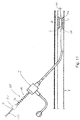
- An alternative aspect of the disclosure is to provide a catheter structure in the form of a guidewire 200 with a marking 230, which may be along a portion external to the body during the procedure.
- the marking 230 may comprise a plurality of spaced marks 232, such as bands. These marks 232 may extend from adjacent a distal end 200a of the guidewire 200 to a proximal end 200b, or any portion thereof.
- the marks 232 may be evenly or unevenly spaced (e.g., the marks may get progressively closer along the length of the guidewire 200).
- the marks 232 may be of a single color, such as for example black, or may be provided in different shades or colors.
- the marks 232 may also comprise hash lines with gradations identified by numbers, letters, or symbols, and thus may effectively form a ruler.
- the marks 232 may be non-radiopaque or may otherwise not be visible under fluoroscopy.
- the marking 230 may also comprise a biocompatible chemiluminescent or photoluminescent material that may be easily viewed in the low light conditions often present during a procedure involving fluoroscopy.
- the marking 230 may be provided in a manner that allows for tactile engagement, such as in the forms of notches, bumps, ridges, recesses, or like structures that can be counted even when not directly visible.
- the marking 230 may be incorporated into the material of the guidewire 200 or placed thereon (including possibly by using printing techniques).
- Each mark 232 may then represent a fixed distance in from the starting point S, such as mark 232 at point B indicating a distance of 20 centimeters (which is simply an exemplary value).
- Point D+1 represents a further distance, such as 21 centimeters, in a known increment (which could be centimeters, but could also be millimeters, meters, inches, feet, etc. or any divisions thereof - the particular units are not considered to be important).
- the marks 232 may be provided up to a pre-determined point D+75 from the starting point S, which in this case represents a distance of 95 centimeters (but again, may be any value depending on the desired scale, catheter length, procedure, etc.).
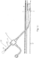
- a guidewire 200 including the marking 230 may be inserted in to a vessel V to a particular location, such as adjacent to a treatment area A.
- This may include a lesion L, as shown, but as noted above may take other forms (e.g, a chronic total occlusion).
- an assessment of the location of the treatment area such as by performing a diagnostic angiogram, may be completed.
- Inserting the guidewire 200 may involve viewing the passing marks 232 during insertion through the introducer I, and either counting them or stopping the insertion process when a known distance is reached (note references S as starting point, D as a first mark, and E as the end point mark). At the point where the marking 230 (such as mark 232') corresponds to the intended distance of insertion, the clinician is assured that the treatment area A has been reached. In the case where the guidewire 200 includes at least partially radiopaque markers, the location may be confirmed using fluoroscopy, the use of which has otherwise been minimized as the result of using the marking 230 to position the guidewire 200 in the vasculature.
- the clinician may choose an appropriate treatment device, such as a catheter (including those examples mentioned here; see catheter 100 in Figure 11 ) having a suitable length.
- the marking 230 may also then be used in positioning the catheter 100 at the treatment area A by using the marks 232 to determine the insertion distance, such as with respect to a reference point F on the guidewire 200 and thereby potentially further reduce the amount of fluoroscopy required.
- the technology disclosed herein may be applied to various types of catheters, without limitation.
- it may be applied to guide catheters, diagnostic catheters, IVUS catheters, OCT catheters, as well as all crossing or thrombectomy catheters (including those using mechanical (e.g., rigid tips, cutters, etc.), laser, fluid, or vibration energy to penetrate through blockages or occlusions).
- crossing catheter 300 may be used to gain access to a desired treatment area A, such as by penetrating through an occlusion O.
- the clinician may note a first mark (such as mark M) on the catheter 300 (such as external to the vasculature) corresponding to the distance of insertion of the catheter at the proximal end or margin X of the treatment area A (which may be relative to an external structure, such as a point on a sheath, introducer I, or the like).
- a second mark 332 such as mark N
- the first and second marks M, N together thus define the length of the treatment area A, and can be measured external to the vasculature in for developing the treatment plan or otherwise.
- a second catheter 400 with a marking 430 comprising corresponding or matching marks 432 may be inserted the precise distance necessary to place the corresponding portion of the catheter 400 for providing the particular treatment at a location corresponding to the treatment area A.
- This may be achieved by noting the relative location of the corresponding marks (such as M, N, which as noted above may be color coded, specially arranged or shaped, identified by an alphanumeric indicator (such as to form a ruler)) or otherwise indicated to correspond to the marks 332 on the crossing catheter 300).
- the technology is a PTA technology including treatment T in the form of an inflatable balloon and an associated guidewire 200 passing through the opening in the occlusion O formed using the crossing catheter 300, but as noted could take other forms.
- this process can be done repeatedly using different types of catheters for different uses, but having matching marking technology, all without the prolonged use of fluoroscopy in order to determine whether the treatment area A has been reached and the associated time involvement.
- the overall length of the procedure may this be reduced, which is especially beneficial since patients requiring the most serious interventions (e.g., CTOs) are usually the least able to tolerate lengthy procedures.
- crossing catheter 300 and second catheter 400 may be provided as a kit. This arrangement would aid the clinician in assuring that the marks are precisely matched, which may of course be done during the manufacturing process.
Landscapes
- Health & Medical Sciences (AREA)
- Life Sciences & Earth Sciences (AREA)
- Heart & Thoracic Surgery (AREA)
- Engineering & Computer Science (AREA)
- Biomedical Technology (AREA)
- Animal Behavior & Ethology (AREA)
- Veterinary Medicine (AREA)
- Public Health (AREA)
- General Health & Medical Sciences (AREA)
- Anesthesiology (AREA)
- Hematology (AREA)
- Pulmonology (AREA)
- Biophysics (AREA)
- Vascular Medicine (AREA)
- Child & Adolescent Psychology (AREA)
- Surgery (AREA)
- Nuclear Medicine, Radiotherapy & Molecular Imaging (AREA)
- Medical Informatics (AREA)
- Molecular Biology (AREA)
- Cardiology (AREA)
- Oral & Maxillofacial Surgery (AREA)
- Transplantation (AREA)
- Media Introduction/Drainage Providing Device (AREA)
Description
- This disclosure relates generally to interventional medical procedures, such as angioplasty, and, more particularly, to a catheter structure with markings to reduce the usage of fluoroscopy during the procedure.
- A clinician performing an endovascular procedure, such as angioplasty, will typically use fluoroscopy in the course of performing a diagnostic angiogram to assess the location of a treatment area (such as where a lesion or blockage is present in the vasculature). Upon gaining guidewire access to the vasculature using additional fluoroscopy, and then inserting the catheter along the guidewire, the clinician will then typically use even more fluoroscopy, either continuously or intermittently (e.g., "spot checking), in order to confirm the catheter has reached the location of the treatment area. As can be appreciated, this conventional approach increases the exposure of the patient and others, including the clinician and assistants, to fluoroscopy and, hence, radiation, which is generally desired to be avoided to the greatest extent possible.
- Accordingly, a need exists for a manner in which to position a catheter structure into the vasculature at a treatment area while reducing the amount or frequency of fluoroscopy used.
-
US 5,114,401 B teaches an apparatus and methods for initial or replacement central venous catherization using a flexible guidewire with markings thereon and substantially translucent non-thrombogenic catheter. The marks on the guidewire are used to establish and maintain as constant the position of the guidewire. Further,US 6,273,895 B1 teaches an apparatus for measuring a desired length of a prosthetic device which is to be implanted in a body cavity of a patient. The apparatus generally includes a helically coiled stent formed of a resiliently deformable material, a plunger which is connected to the proximal end of the stent, a sheath which slides over the plunger and stent when the plunger and sheath are used to insert and removably deploy the stent into the body cavity, and a scale for measuring an indication of the length of the stent once removably deployed in the body cavity. - Moreover, a catheter assembly for providing precise placement of a catheter distal end at a desired location within the patient vasculature is disclosed in
US 2008/0255475 A1 . The catheter assembly comprises a catheter including an elongate body that defines a proximal end, a distal end, and a lumen extending therebetween. A guidewire is included and is configured for being received within the lumen of the catheter and for guiding the catheter through the patient vasculature. The guidewire includes a plurality of depth markings along at least a portion of a length of a guidewire. - The present invention relates to the kit for treating the treatment area in a vasculature of a patient according to
claim 1. The dependent claims relate to preferred embodiments. - The examples do not comprise all features of
claim 1. - One example is to provide a catheter structure, such as a balloon catheter, guidewire, or the like, with markings perceptible outside of the vasculature for use in determining at a location external to the body the position of the catheter structure relative to a treatment area.
- One example relates to an apparatus for use by a clinician in treating the vasculature. The apparatus may include a catheter structure having a shaft including a first distal portion adapted for positioning at the treatment area and a proximal portion including a marking perceptible by the clinician external to the vasculature without the use of fluoroscopy, the marking being representative of a length from a pre-determined starting point on the catheter structure. Consequently, the markings may be used to position the catheter structure a distance in the vasculature corresponding to the length with minimal use of fluoroscopy.
- The marking may comprise a plurality of regularly spaced marks or irregularly spaced marks. In one aspect, the marking may be printed on the catheter structure. The markings may comprise a plurality of first marks and at least one second mark different from the plurality of first marks. For example, the first marks may comprise spaced bands and the second mark may comprise an alphanumerical indicia. The marking may be provided adjacent a hub associated with the catheter structure. In a further aspect, the marking may be luminescent, such as chemiluminescent or photoluminescent.
- In a further example, the catheter structure may comprise a balloon adjacent to a tip including the pre-determined starting point. One or more radiopaque markings may be adjacent to the balloon.
- The catheter structure may include a treatment element selected from the group consisting of a drug, a stent, a graft, a cutter, a focused force wire, or any combination thereof. Additionally, the catheter structure may comprise a guidewire, and may be adapted for slidably receiving the guidewire.
- In another example, an apparatus for treating a treatment area at an intravascular location in a body is disclosed. The apparatus may include a catheter including a shaft having a distal portion including a balloon and a proximal portion including at least one marking arranged for being viewed at a reference point external to the body for identifying a distance from the treatment area to the reference point. The balloon may further include a treatment element
- selected from the group consisting of a stent, a graft, a cutter, a focused force wire, or any combination thereof.
- Another example, relates to a method of treating a treatment area in a body. The method may comprise inserting a distal portion of a guidewire to the treatment area, determining a position of a first marking on a proximal portion of the guidewire relative to a reference point, and inserting a catheter a distance corresponding to the first marking.
- A further example, relates to an apparatus for use by a clinician in treating the vasculature. The apparatus may include a catheter structure having a shaft including a first distal portion adapted for positioning at the treatment area and a proximal portion, and means external to the vasculature for determining a length from a pre-determined starting point on the catheter structure, whereby the determining means may be used to position the catheter structure a distance in the vasculature corresponding to the length with minimal use of fluoroscopy.
- Another example comprises a catheter including a ruler. A further example comprises a guidewire including a ruler. A catheter comprising a ruler may be provided and/or used in combination with a guidewire comprising a ruler.
- In another example, a crossing catheter is provided including a plurality of markings for determining a distance of insertion into a patient's vasculature. The plurality of markings may comprise a ruler.
- An additional example, relates to a method of forming a catheter structure. The method may comprise comprising providing a marking perceptible to a clinician on a first portion of the catheter structure external to the vasculature to provide a representation of an amount a second portion of the catheter structure has been inserted into the vasculature. The providing step may comprise printing the marking on the catheter structure. The providing step may further comprise providing a plurality of first marks and at least one second mark different from the plurality of first marks. The first marks may comprise spaced bands and the second mark may comprise an alphanumerical indicia. In one aspect, the amount represents a total distance the second portion of the catheter structure has been inserted into the vasculature from a reference point external to the vasculature.
- Any of the catheters and/or guidewires disclosed herein may be provided together in a kit for the treatment of a treatment area in a patient's vasculature. For example, a kit for treating a treatment area in the vasculature. The kit may include a first crossing catheter having a first shaft including a first distal portion adapted for positioning at or selected from the group consisting of a stent, a graft, a cutter, a focused force wire, or any combination thereof.
- Another example relates to a method of treating a treatment area in a body. The method may comprise inserting a distal portion of a guidewire to the treatment area, determining a position of a first marking on a proximal portion of the guidewire relative to a reference point, and inserting a catheter a distance corresponding to the first marking.
- A further example relates to an apparatus for use by a clinician in treating the vasculature. The apparatus may include a catheter structure having a shaft including a first distal portion adapted for positioning at the treatment area and a proximal portion, and means external to the vasculature for determining a length from a pre-determined starting point on the catheter structure, whereby the determining means may be used to position the catheter structure a distance in the vasculature corresponding to the length with minimal use of fluoroscopy.
- Another example comprises a catheter including a ruler. A further example comprises a guidewire including a ruler. A catheter comprising a ruler is provided in combination with a guidewire comprising a ruler.
- In another example, a crossing catheter is provided including a plurality of markings for determining a distance of insertion into a patient's vasculature. The plurality of markings may comprise a ruler.
- An additional example relates to a method of forming a catheter structure. The method may comprise comprising providing a marking perceptible to a clinician on a first portion of the catheter structure external to the vasculature to provide a representation of an amount a second portion of the catheter structure has been inserted into the vasculature. The providing step may comprise printing the marking on the catheter structure. The providing step may further comprise providing a plurality of first marks and at least one second mark different from the plurality of first marks. The first marks may comprise spaced bands and the second mark may comprise an alphanumerical indicia. In one aspect, the amount represents a total distance the second portion of the catheter structure has been inserted into the vasculature from a reference point external to the vasculature.
- Any of the catheters and/or guidewires disclosed herein may be provided together in a kit for the treatment of a treatment area in a patient's vasculature. For example, a kit for treating a treatment area in the vasculature. The kit may include a first crossing catheter having a first shaft including a first distal portion adapted for positioning at or including a first distal portion adapted for positioning at or near the treatment area and a first proximal portion including a first marking at a first location, and a second catheter having a second shaft including a second distal portion adapted for positioning at the treatment area and a second proximal portion including a second marking at a second location substantially matching a first location of the first marking. Each of the first marking and the second marking may be visible external to the patient's body without the use of fluoroscopy. In one aspect, the second distal portion of the second catheter comprises a balloon. The second catheter may comprise a treatment element selected from the group consisting of a drug, a stent, a graft, a cutter, a focused force wire, or any combination thereof. Furthermore, the crossing catheter may be adapted for penetrating into or through an occlusion at the treatment area.
- Another example relates to a kit for treating a treatment area in the vasculature, comprising a first crossing catheter having a first shaft including a first distal portion adapted for positioning at or near the treatment area and a first proximal portion including a first marking at a first location corresponding to a first margin of the treatment area and a second marking at a second location corresponding to a second margin of the treatment area, and a second catheter having a second shaft including a second distal portion adapted for positioning at the treatment area and a second proximal portion including a third marking at a third location substantially matching the first location or the second location on the first, crossing catheter. The second catheter may further include a fourth marking on the second proximal portion at a fourth location corresponding to the other of the first location or the second location on the first, crossing catheter. In one aspect, the second catheter may include a technology selected from the group consisting of an artherectomy technology, a thrombectomy technology, a PTA technology, a stent technology, and any combination of the foregoing. In any of the above examples, the crossing catheter may be adapted to penetrate into an occlusion or the occlusion at the treatment area. The crossing catheter may be adapted to apply energy for penetrating into an occlusion or the occlusion. In a further aspect, the crossing catheter comprises a cutter, a vibrator, a source of light, a source of fluid, a nozzle, a rigid or tapered distal tip, or any combination of the foregoing.
- In still a further example, a kit is disclosed for treating a treatment area in a vasculature of a patient. The kit of this further example may comprise a first crossing catheter having a first shaft including a first distal portion adapted for positioning at the treatment area and a first proximal portion including a plurality of first markings perceptible by the clinician external to the vasculature without the use of fluoroscopy, each of the plurality of first markings being representative of a length from a first predetermined starting point on the first crossing catheter, and a second catheter having a second shaft including a second distal portion adapted for positioning at the treatment area and a second proximal portion including a plurality of second markings perceptible by the clinician external to the vasculature without the use of fluoroscopy, each of the plurality of second markings being representative of a length from a second predetermined starting point of the second catheter, wherein a distance between the first predetermined starting point and each of the first markings corresponds to a distance between the second predetermined starting point and each of the second markings.
- In this example, the plurality of first markings may be spaced at regular intervals from one another. Each of the first shaft and the second shaft may further include alphanumeric markings corresponding to each of the first markings and the second markings. At least one of the first markings or the second markings may be chemiluminescent or photoluminescent. In one aspect, at least one of the first markings or the second markings comprises spaced bands.
- The second catheter may comprise a balloon adjacent a tip including the second predetermined starting point. In addition, a radiopaque marker may be adjacent the balloon.
- In another example, a kit for treating a treatment area in a vasculature of a patient is disclosed. The kit comprises a first crossing catheter having a first shaft including a first distal portion adapted for positioning at the treatment area and a first proximal portion including a first ruler thereon. The first ruler may be perceptible by the clinician external to the vasculature without the use of fluoroscopy for measuring a distance from a first predetermined starting point on the first crossing catheter. A second catheter having a second shaft including a second distal portion adapted is for positioning at the treatment area and a second proximal portion including a second ruler thereon. The second ruler is also perceptible by the clinician external to the vasculature without the use of fluoroscopy for measuring a distance from a second predetermined starting point of the second catheter.
- A further example relates to a kit for treating a treatment area in a vasculature of a patient comprising a first crossing catheter having a first shaft including first means for measuring a plurality of first distances from a first predetermined point on the first shaft, and a second catheter having a second shaft including second means for measuring a plurality of second distances from a second predetermined point on the second shaft, wherein the first means for measuring and the second means for measuring are are perceptible by the clinician external to the vasculature without the use of fluoroscopy (and may, for example, be non-radiopaque in nature), and wherein each of the plurality of first distances corresponds to at least one of the plurality of second distances. The second catheter may comprise a balloon adjacent a distal end of the second shaft, and wherein the second predetermined point may be an end of the balloon. The second catheter may further comprise a radiopaque marker adjacent the balloon.
- An embodiment is a kit for treating a treatment area in a vasculature of a patient. The kit comprises a guidewire having a first distal portion adapted for positioning at or near the treatment area and a first proximal portion including a plurality of first markings perceptible by the clinician external to the vasculature without the use of fluoroscopy, each of the plurality of first markings being representative of a length from a first predetermined starting point on the catheter, and a catheter having a shaft including second distal portion adapted for positioning at the treatment area and a second proximal portion including a plurality of second markings perceptible by the clinician external to the vasculature without the use of fluoroscopy, each of the plurality of second markings being representative of a length from a second predetermined starting point of the second catheter, wherein a distance between the first predetermined starting point and each of the first markings corresponds to a distance between the second predetermined starting point and each of the second markings.
- The catheter comprises a balloon. The balloon is located at a distal end of the catheter, and the second predetermined starting point may be located at a proximal end or a distal end of the balloon. In addition, a radiopaque marker may be adjacent the balloon.
- The kit may also be provided such that the catheter comprises a treatment element selected from the group consisting of a drug, a stent, a graft, a cutter, a focused force wire, or any combination thereof. The catheter may include a technology selected from the group consisting of an artherectomy technology, a thrombectomy technology, a PTA technology, a stent technology, and any combination of the foregoing.
- The plurality of first markings may be spaced at regular intervals from one another.
- The guidewire and the catheter may further include alphanumeric markings corresponding to each of the first markings and the second markings. At least one of the first markings or the second markings may be chemiluminescent or photoluminescent. In another aspect, at least one of the first markings or the second markings may comprise spaced bands.
- As disclosed in another example, a kit for treating a treatment area in a vasculature of a patient comprises a guidewire including a first distal portion adapted for positioning at the treatment area and a first proximal portion including a first ruler thereon. The first ruler is perceptible by the clinician external to the vasculature without the use of fluoroscopy, and may be non-radiopaque. The first ruler may be adapted for measuring a distance from a first predetermined starting point on the guidewire, and a catheter having a shaft including a second distal portion adapted for positioning at the treatment area and a second proximal portion including a second ruler thereon. The second ruler may be perceptible by the clinician external to the vasculature without the use of fluoroscopy, such as for example, being non-radiopaque. The second ruler may be adapted for measuring a distance from a second predetermined starting point of the catheter.
- A still further example relates to a kit for treating a treatment area in a vasculature of a patient. The kit comprises a guidewire including first means for measuring a plurality of first distances from a first predetermined point on the guidewire, and a catheter including second means for measuring a plurality of second distances from a second predetermined point on the catheter. The first means for measuring and the second means for measuring may be non-radiopaque in nature and are perceptible by the clinician external to the vasculature without the use of fluoroscopy. Each of the plurality of first distances may correspond (e.g., be equal to) at least one of the plurality of second distances. The catheter may comprise a balloon adjacent a distal end of the catheter, and the second predetermined point may be an end of the balloon. The catheter may further comprise a radiopaque marker adjacent the balloon.
- In another example, a device for treating a treatment area in the vasculature of a patient is disclosed, said device comprising a crossing catheter having a shaft including a distal portion adapted for positioning at or near the treatment area and a proximal portion including a plurality of markings, said markings being visible external to the patient's body without the use of fluoroscopy.
- In one example, the plurality of markings may comprise a first marking at a first location corresponding to a first margin of the treatment area and a second marking at a second location corresponding to a second margin of the treatment area.
- In another example, each of the plurality of markings may be representative of at least one known length from a predetermined starting point on the crossing catheter. These plurality of markings may be spaced at regular intervals from one another. The shaft may additionally include alphanumeric markings corresponding to each of the plurality of markings.
- In any of the above embodiments and examples, at least one of the markings may be chemiluminescent or photoluminescent. Furthermore, at least one of the markings may comprise a spaced band.
- In a further example, a device for treating a treatment area in a vasculature of a patient is disclosed, said device comprising a crossing catheter having a shaft including a distal portion adapted for positioning at the treatment area and a proximal portion including a ruler thereon, said ruler being perceptible by the clinician external to the vasculature without the use of fluoroscopy for measuring a distance from a predetermined starting point on the crossing catheter.
- In any of the above examples, the crossing catheter may be adapted for penetrating into or through an occlusion at the treatment area.
- In any of the above embodiments and examples, a marking perceptible by the clinician external to the vasculature without the use of fluoroscopy may be a non-radiopaque marking.
-
-
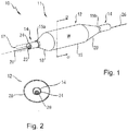
Figure 1 is a perspective view of a catheter and balloon according to an example disclosed herein. -
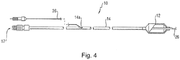
Figure 2 is a cross-section of the balloon ofFigure 1 along line 2-2. -
Figure 3 is a further perspective of the catheter and balloon according to an example disclosed herein. -
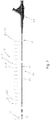
Figure 4 is an elevational view of a catheter and guidewire according to a further embodiment disclosed herein. -
Figure 5 and Figure 6 show details of a catheter structure according to an example of the present disclosure. -
Figure 7 shows details of a catheter structure according to a further example of the present disclosure. -
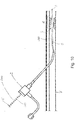
Figure 8 shows one way of using a catheter structure according to an example of the present disclosure. -
Figure 9 shows details of a catheter structure in the form of a guidewire according to another aspect of the disclosure. -
Figure 10 andFigure 11 show a way of using the guidewire ofFigure 9 according to an embodiment. -
Figure 12 ,Figure 13 , andFigure 14 show one way of using a marked crossing catheter in combination with another catheter according to a further example. - The description provided below and in regard to the figures applies to all embodiments and examples unless noted otherwise, and features common to each embodiment and examples are similarly shown and numbered.
- Provided is a catheter structure in the form of a
tubular catheter 10 capable of being actuated in some manner in order to provide a treatment. In this one example for purposes of illustration, thecatheter 10 includes a distal portion 11 with an actuatable element in the form of aballoon 12 mounted on acatheter tube 14. Referring toFigures 1, 2 , and3 , theballoon 12 has anintermediate section 16, or "barrel" having the working surface W, and endsections end sections intermediate section 16 to the catheter tube 14 (and thussections balloon 12 is sealed tocatheter tube 14 at balloon ends (proximal 15a and distal 15b) on theend sections balloon 12 via one ormore inflation lumens 17 extending withincatheter tube 14 and communicating with the interior of theballoon 12. - The
catheter tube 14 also includes an elongated,tubular shaft 24 forming alumen 23 that directs another catheter structure, such asguidewire 26, through thecatheter 10. As illustrated inFigure 3 , thisguidewire 26 may be inserted through afirst port 25 of aconnector 27, such as a hub, into thelumen 23 to achieve an "over the wire" (OTW) arrangement, but could also be provided in a "rapid exchange" configuration in which theguidewire 26 enters the lumen through alateral opening 14a closer to the distal end (seeFigure 4 ). Asecond port 29 may also be associated withcatheter 10, such as by way ofconnector 27, for introducing a fluid (e.g., saline, a contrast agent, or both) into the interior of theballoon 12 via theinflation lumen 17. -
Balloon 12 may include a single ormulti-layered balloon wall 28. Theballoon 12 may be a non-compliant balloon having aballoon wall 28 that maintains its size and shape in one or more directions when the balloon is inflated. Theballoon 12 in such case also has a predetermined surface area that remains constant during and after inflation, also has a predetermined length and pre-determined circumference that each, or together, remain constant during and after inflation. However, theballoon 12 could be semi-compliant or compliant instead, depending on the particular use. Thecatheter 10 may also be adapted for use in connection with resolving chronic total occlusions or artherectomy, and thus may be provided with a cutter or cutting element. Thecatheter 10 may also be used in connection with a drug, a cutting element, a stent, a graft, or like treatment. - In order to provide an enhanced locatability during an interventional procedure while minimizing the use of fluoroscopy, the
catheter 10 may be provided with a marking 30 perceptible along a portion external to the vasculature during the procedure, such as on or alongtube 14. As shown inFigure 5 , the marking 30 may comprise a plurality of spacedmarks 32, such as circular or partially circular (e.g., 1-359 degrees) bands surrounding theshaft 14 and positioned at pre-determined intervals. Thesemarks 32 may extend from adjacent theconnector 27 to theproximal end 15a of theballoon 12, or any portion thereof (which is considered the "proximal portion" of thecatheter 10, as contrasted with the distal portion including the balloon 12). - The
marks 32 may be evenly or unevenly spaced (e.g., the marks may get progressively closer along the length of the shaft 24). Themarks 32 may be of a single color, such as for example black as shown inFigure 5 , but as shown inFigure 6 may also be provided in different shades or colors. Themarks 32 may also comprise hash lines with gradations identified by numbers, letters, or symbols and, thus, may effectively form a ruler. In any case, themarks 32 may be non-radiopaque or otherwise may not be adapted to fluoresce. - The marking 30 may also comprise a biocompatible chemiluminescent or photoluminescent material that may be easily viewed in the low light conditions often present during a procedure involving fluoroscopy. Alternatively or additionally, the marking 30 may be provided in a manner that allows for tactile perception, such as in the forms of notches, bumps, ridges, recesses, or like structures that can be counted even when not directly visible. In any case, the marking 30 may be incorporated directly into the material of the
tube 14 or placed thereon (including possibly by using printing techniques). - A further example is shown in
Figure 7 . In this example, it can be understood that the marking 30 is provided on thecatheter 10 in the form of spacedmarks 32, each of which represents a known distance from a pre-determined, fixed location on thecatheter 10. In this one illustrated example, the fixed location is the distal tip P, which thus may be considered the starting point S in terms of the measured distance (but the starting point S could be located elsewhere on a structure connected to thecatheter 10, such as at the balloondistal end 15b, along the body of theballoon 12, or at the balloonproximal end 15a, as non-limiting examples). Eachmark 32 may then represent a fixed distance in from the starting point S, such asmark 32 at point D indicating a distance of 20 centimeters (which is simply an exemplary value). Point D+1 represents a further distance, such as 21 centimeters, in a known increment (which could be centimeters, but could also be millimeters, meters, inches, feet, etc. or portions thereof - the particular units are not considered to be important). Themarks 32 may be provided up to a pre-determined end point E, such as D+75 from the starting point S, which in this case represents 95 centimeters (but again, may be any value depending on the desired scale, catheter length, procedure, etc.). - Optionally, the
catheter 10 may also be provided with one or more secondary markings 34 in the form of printed indicia representative of distance, such as in the form of alphanumeric characters. For example, between marking D+10 and marking D+11 in the illustrated example, the number "30" may be printed on the shaft as an indication of the distance from the zero point Z, which here is thirty centimeters (but again is simply an example). This allows the clinician to assess the value foradjacent marks 32 quickly, even when provided in a form that does not admit to being perceptable as a particular distance (e.g., a band). The use of characters (e.g., X = 10 cm, L = 50, C=100) is also possible to determine the distance, as is the use of a key in connection therewith (e.g., A=10 cm, B=50 cm, C=100 cm). - In use, and with reference to
Figure 8 , acatheter 100 including the marking 30 may be inserted in to a vessel V to a particular treatment area A, which is shown as comprising a lesion L but may take other forms (e.g, a chronic total occlusion, or a location at which the application of a stent, graft, or the like, is desired). This may be done following an assessment of the location of the treatment area, such as by performing a diagnostic angiogram. Inserting thecatheter 100 may involve viewing the passing marks 32 during insertion through the introducer I, and either counting them or stopping the insertion process when a known distance is reached. At the point where the marking 30 (such as mark 32') corresponds to the intended distance of insertion, the clinician is assured that the treatment area A has been reached by the distal portion of the catheter 10 (especially when the tip P reflects the starting point S, in which case the known length of the lesion L and the known length of theballoon 12 or other treatment may be used to achieve proper positioning using simple math). Radiopaque markers, such asbands 102, may optionally be provided to aid in confirming the location using fluoroscopy, the use of which has otherwise been minimized as the result of using the marking 30 to position thecatheter 100. - An alternative aspect of the disclosure is to provide a catheter structure in the form of a guidewire 200 with a marking 230, which may be along a portion external to the body during the procedure. As shown in
Figure 9 , the marking 230 may comprise a plurality of spaced marks 232, such as bands. These marks 232 may extend from adjacent a distal end 200a of the guidewire 200 to a proximal end 200b, or any portion thereof. - The marks 232 may be evenly or unevenly spaced (e.g., the marks may get progressively closer along the length of the guidewire 200). The marks 232 may be of a single color, such as for example black, or may be provided in different shades or colors. The marks 232 may also comprise hash lines with gradations identified by numbers, letters, or symbols, and thus may effectively form a ruler. The marks 232 may be non-radiopaque or may otherwise not be visible under fluoroscopy.
- The marking 230 may also comprise a biocompatible chemiluminescent or photoluminescent material that may be easily viewed in the low light conditions often present during a procedure involving fluoroscopy. Alternatively or additionally, the marking 230 may be provided in a manner that allows for tactile engagement, such as in the forms of notches, bumps, ridges, recesses, or like structures that can be counted even when not directly visible. In any case, the marking 230 may be incorporated into the material of the guidewire 200 or placed thereon (including possibly by using printing techniques).
- Each mark 232 may then represent a fixed distance in from the starting point S, such as mark 232 at point B indicating a distance of 20 centimeters (which is simply an exemplary value). Point D+1 represents a further distance, such as 21 centimeters, in a known increment (which could be centimeters, but could also be millimeters, meters, inches, feet, etc. or any divisions thereof - the particular units are not considered to be important). The marks 232 may be provided up to a pre-determined point D+75 from the starting point S, which in this case represents a distance of 95 centimeters (but again, may be any value depending on the desired scale, catheter length, procedure, etc.).
- In use, with reference to
Figure 10 , a guidewire 200 including the marking 230 may be inserted in to a vessel V to a particular location, such as adjacent to a treatment area A. This may include a lesion L, as shown, but as noted above may take other forms (e.g, a chronic total occlusion). Prior to the insertion, an assessment of the location of the treatment area, such as by performing a diagnostic angiogram, may be completed. - Inserting the guidewire 200 may involve viewing the passing marks 232 during insertion through the introducer I, and either counting them or stopping the insertion process when a known distance is reached (note references S as starting point, D as a first mark, and E as the end point mark). At the point where the marking 230 (such as mark 232') corresponds to the intended distance of insertion, the clinician is assured that the treatment area A has been reached. In the case where the guidewire 200 includes at least partially radiopaque markers, the location may be confirmed using fluoroscopy, the use of which has otherwise been minimized as the result of using the marking 230 to position the guidewire 200 in the vasculature.
- With knowledge of the distance to the treatment area A thus provided by the marking 230 on the guidewire 200, the clinician may choose an appropriate treatment device, such as a catheter (including those examples mentioned here; see
catheter 100 inFigure 11 ) having a suitable length. The marking 230 may also then be used in positioning thecatheter 100 at the treatment area A by using the marks 232 to determine the insertion distance, such as with respect to a reference point F on the guidewire 200 and thereby potentially further reduce the amount of fluoroscopy required. - The technology disclosed herein may be applied to various types of catheters, without limitation. For example, it may be applied to guide catheters, diagnostic catheters, IVUS catheters, OCT catheters, as well as all crossing or thrombectomy catheters (including those using mechanical (e.g., rigid tips, cutters, etc.), laser, fluid, or vibration energy to penetrate through blockages or occlusions). In one particular example, and with reference to
Figure 12 , such acrossing catheter 300 may be used to gain access to a desired treatment area A, such as by penetrating through an occlusion O. - Using the marking 330 comprised of marks 332 (which may be the same form as
marks 32 or 232) in connection with such acrossing catheter 300, the clinician may note a first mark (such as mark M) on the catheter 300 (such as external to the vasculature) corresponding to the distance of insertion of the catheter at the proximal end or margin X of the treatment area A (which may be relative to an external structure, such as a point on a sheath, introducer I, or the like). Once the crossingcatheter 300 is advanced to the end of the treatment area A, such as at the distal end or margin Y of the occlusion O (seeFigure 13 ), a second mark 332 (such as mark N) on the crossingcatheter 300 may be noted. The first and second marks M, N together thus define the length of the treatment area A, and can be measured external to the vasculature in for developing the treatment plan or otherwise. - Subsequently, a
second catheter 400 with a marking 430 comprising corresponding or matching marks 432 (such as, for example, a catheter including artherectomy technology (e.g., any of orbital, rotational, laser, and directional devices), thrombectomy technology, PTA technology, stent technology, or any other technology) may be inserted the precise distance necessary to place the corresponding portion of thecatheter 400 for providing the particular treatment at a location corresponding to the treatment area A. This may be achieved by noting the relative location of the corresponding marks (such as M, N, which as noted above may be color coded, specially arranged or shaped, identified by an alphanumeric indicator (such as to form a ruler)) or otherwise indicated to correspond to the marks 332 on the crossing catheter 300). In the illustrated example, the technology is a PTA technology including treatment T in the form of an inflatable balloon and an associated guidewire 200 passing through the opening in the occlusion O formed using the crossingcatheter 300, but as noted could take other forms. - As should be appreciated, this process can be done repeatedly using different types of catheters for different uses, but having matching marking technology, all without the prolonged use of fluoroscopy in order to determine whether the treatment area A has been reached and the associated time involvement. The overall length of the procedure may this be reduced, which is especially beneficial since patients requiring the most serious interventions (e.g., CTOs) are usually the least able to tolerate lengthy procedures.
- As can be further appreciated, the crossing
catheter 300 andsecond catheter 400 may be provided as a kit. This arrangement would aid the clinician in assuring that the marks are precisely matched, which may of course be done during the manufacturing process. - While the disclosure presents certain embodiments and examples to illustrate the inventive concepts, numerous modifications, alterations, and changes to the described embodiments are possible without departing from the scope, as defined in the appended claims. For example, any ranges and numerical values provided in the various embodiments are subject to variation due to tolerances, due to variations in environmental factors and material quality, and due to modifications of the structure and shape of the balloon, and thus can be considered to be approximate and the term "approximately" means that the relevant value can, at minimum, vary because of such factors. Also, the drawings, while illustrating the inventive concepts, are not to scale, and should not be limited to any particular sizes or dimensions. Accordingly, it is intended that the present disclosure not be limited to the described embodiments, but that it has the full scope defined by the language of the following claims, and equivalents thereof.
Claims (4)
- A kit for treating a treatment area in a vasculature of a patient, said kit comprising:a guidewire (200) including a first distal portion adapted for positioning at the treatment area (A) and a first proximal portion including a first ruler (230) thereon, said first ruler being perceptible by the clinician external to the vasculature without the use of fluoroscopy, said first ruler adapted for measuring a distance from a first predetermined starting point (S) on the guidewire; anda catheter (100) having a shaft including a second distal portion adapted for positioning at the treatment area (A) and a second proximal portion including a second ruler thereon, said second ruler (30) being perceptible by the clinician external to the vasculature without the use of fluoroscopy, said second ruler adapted for measuring a distance from a second predetermined starting point (S) on the catheter, characterized in that the catheter comprises a balloon (12) adjacent a distal end of the catheter, and wherein the second predetermined point (S) is an end of the balloon (15a, b).
- The kit according to claim 1, wherein the catheter (100) further comprises a radiopaque marker adjacent the balloon.
- The kit according to any one of the foregoing claims, wherein the catheter comprises a treatment element selected from the group consisting of a drug, a stent, a graft, a cutter, a focused force wire, or any combination thereof.
- The kit according to any one of the foregoing claims, wherein the catheter includes a technology selected from the group consisting of an artherectomy technology, athrombectomy technology, a PTA technology, a stent technology, and any combination of the foregoing.
Applications Claiming Priority (3)
| Application Number | Priority Date | Filing Date | Title |
|---|---|---|---|
| US201461972580P | 2014-03-31 | 2014-03-31 | |
| US201462083745P | 2014-11-24 | 2014-11-24 | |
| PCT/US2015/023574 WO2015153599A1 (en) | 2014-03-31 | 2015-03-31 | Catheter structures for reducing fluoroscopy usage during endovascular procedures |
Publications (2)
| Publication Number | Publication Date |
|---|---|
| EP3125984A1 EP3125984A1 (en) | 2017-02-08 |
| EP3125984B1 true EP3125984B1 (en) | 2021-07-28 |
Family
ID=52829460
Family Applications (1)
| Application Number | Title | Priority Date | Filing Date |
|---|---|---|---|
| EP15716350.2A Active EP3125984B1 (en) | 2014-03-31 | 2015-03-31 | Catheter structures for reducing fluoroscopy usage during endovascular procedures |
Country Status (13)
| Country | Link |
|---|---|
| US (1) | US11458286B2 (en) |
| EP (1) | EP3125984B1 (en) |
| JP (2) | JP2017512587A (en) |
| KR (1) | KR102364071B1 (en) |
| CN (1) | CN106456938A (en) |
| AU (4) | AU2015240941B2 (en) |
| BR (1) | BR112016021726B1 (en) |
| CA (1) | CA2944354C (en) |
| CL (1) | CL2016002335A1 (en) |
| MX (1) | MX2016012730A (en) |
| NZ (1) | NZ724237A (en) |
| RU (2) | RU2686297C2 (en) |
| WO (1) | WO2015153599A1 (en) |
Families Citing this family (12)
| Publication number | Priority date | Publication date | Assignee | Title |
|---|---|---|---|---|
| DE202014100863U1 (en) * | 2014-02-26 | 2014-03-14 | Cormedics Medizintechnik GmbH | Guidewire for medical devices |
| US11922823B2 (en) | 2016-01-24 | 2024-03-05 | C.R. Bard, Inc. | Demonstration apparatus for a medical device and related method |
| EP3295983A1 (en) | 2016-09-20 | 2018-03-21 | Imds R&D Bv | Trapping catheter and kit and method for preparing a trapping catheter |
| US10512756B2 (en) | 2017-01-12 | 2019-12-24 | Cardiac Dimensions Pty. Ltd. | Sizing catheters |
| US11369772B2 (en) * | 2017-09-28 | 2022-06-28 | C.R. Bard, Inc. | Catheter with movable indicator |
| US11096757B2 (en) | 2018-06-28 | 2021-08-24 | Medtronic, Inc. | Implantable medical lead indicators |
| CN211884905U (en) | 2019-08-22 | 2020-11-10 | 贝克顿·迪金森公司 | Balloon dilatation catheter and balloon thereof |
| KR102450520B1 (en) * | 2020-05-22 | 2022-10-05 | 박용범 | Varicose vein surgery kit |
| CN114601449A (en) * | 2020-12-07 | 2022-06-10 | 深圳市先健呼吸科技有限公司 | Measuring device |
| RU208940U1 (en) * | 2021-09-09 | 2022-01-24 | Ашот Михайлович Григорьян | Device for temporary balloon occlusion of the infrarenal aorta |
| KR20230039252A (en) * | 2021-09-14 | 2023-03-21 | 박현수 | intravenous catheter |
| KR102596967B1 (en) * | 2021-09-14 | 2023-10-31 | 박현수 | arterial catheter |
Family Cites Families (98)
| Publication number | Priority date | Publication date | Assignee | Title |
|---|---|---|---|---|
| US550238A (en) | 1895-11-26 | Horace russel allen | ||
| JPS52473Y1 (en) * | 1970-12-29 | 1977-01-07 | ||
| US4133303A (en) | 1977-04-28 | 1979-01-09 | The Kendall Company | Hemostatic catheter and method |
| US4776347A (en) | 1980-05-20 | 1988-10-11 | E. R. Squibb & Sons, Inc. | Device for devloping control of spincter-type muscles |
| DE3361309D1 (en) | 1982-02-05 | 1986-01-09 | British Telecomm | Laser light sources |
| US4464175A (en) | 1982-08-25 | 1984-08-07 | Altman Alan R | Multipurpose tamponade and thrombosclerotherapy tube |
| US5030227A (en) | 1988-06-02 | 1991-07-09 | Advanced Surgical Intervention, Inc. | Balloon dilation catheter |
| US4981470A (en) | 1989-06-21 | 1991-01-01 | Synectics Medical, Inc. | Intraesophageal catheter with pH sensor |
| US5021043A (en) | 1989-09-11 | 1991-06-04 | C. R. Bard, Inc. | Method and catheter for dilatation of the lacrimal system |
| US5209730A (en) | 1989-12-19 | 1993-05-11 | Scimed Life Systems, Inc. | Method for placement of a balloon dilatation catheter across a stenosis and apparatus therefor |
| US5114401A (en) * | 1990-02-23 | 1992-05-19 | New England Deaconess Hospital Corporation | Method for central venous catheterization |
| US5109869A (en) | 1991-01-22 | 1992-05-05 | Baxter International Inc. | Disposable uterine sound device |
| US5437290A (en) | 1991-09-06 | 1995-08-01 | Board Of Trustees Of The Leland Stanford Jr. University | System and method for monitoring intraluminal device position |
| US5324269A (en) | 1991-09-19 | 1994-06-28 | Baxter International Inc. | Fully exchangeable dual lumen over-the-wire dilatation catheter with rip seam |
| US5163927A (en) | 1991-10-17 | 1992-11-17 | Imagyn Medical, Inc. | Linear eversion catheter system with position indicating indicia |
| WO1993020876A1 (en) | 1992-04-14 | 1993-10-28 | Du-Med B.V. | Electronic catheter displacement sensor |
| US5836895A (en) | 1995-01-09 | 1998-11-17 | Arzco Medical Systems, Inc. | Esophageal catheter with gauge |
| EP0723786A1 (en) | 1995-01-30 | 1996-07-31 | Cardiovascular Concepts, Inc. | Lesion measurement catheter and method |
| US5591128A (en) | 1995-03-03 | 1997-01-07 | Sithole; Deborah I. | Gastrostomy tube |
| CA2223399C (en) * | 1995-06-06 | 2003-08-05 | Corvita Corporation | Endovascular measuring apparatus, loading and deployment means |
| US5657764A (en) | 1995-08-30 | 1997-08-19 | Uromed Corporation | Device and method for determining the length of a urethra |
| US5864961A (en) | 1996-09-04 | 1999-02-02 | Vaughan; Ward P. | Urethral probe for diagnosing stress incontinence |
| US6494848B1 (en) | 1996-12-19 | 2002-12-17 | St. Jude Medical Puerto Rico B.V. | Measuring device for use with a hemostatic puncture closure device |
| US5851210A (en) | 1997-03-21 | 1998-12-22 | Torossian; Richard | Stent delivery system and method |
| JPH10323386A (en) | 1997-03-21 | 1998-12-08 | Nippon Sherwood Medical Ind Ltd | Antibacterial catheter against blood coagulation |
| US6143016A (en) * | 1997-04-21 | 2000-11-07 | Advanced Cardiovascular Systems, Inc. | Sheath and method of use for a stent delivery system |
| DE19732965A1 (en) | 1997-07-31 | 1999-02-18 | Knoerig Joachim Michael Dr | Balloon catheter |
| WO1999016495A1 (en) | 1997-10-01 | 1999-04-08 | Boston Scientific Limited | Preinsertion measurement of catheters |
| US6450989B2 (en) | 1998-04-27 | 2002-09-17 | Artemis Medical, Inc. | Dilating and support apparatus with disease inhibitors and methods for use |
| US6210338B1 (en) | 1998-08-21 | 2001-04-03 | Aga Medical Corp. | Sizing catheter for measuring cardiovascular structures |
| US6241678B1 (en) | 1998-08-21 | 2001-06-05 | Aga Medical Corporation | Sizing catheter for measuring septal defects |
| GB2355797A (en) | 1999-10-26 | 2001-05-02 | Anthony James Ivor Scriven | A guidewire having measurement markings |
| US6575932B1 (en) | 1999-12-02 | 2003-06-10 | Ottawa Heart Institute | Adjustable multi-balloon local delivery device |
| WO2001072221A1 (en) | 2000-03-27 | 2001-10-04 | Wilson-Cook Medical Inc. | Apparatus for measuring esophageal sphincter compliance |
| US6620114B2 (en) | 2000-10-05 | 2003-09-16 | Scimed Life Systems, Inc. | Guidewire having a marker segment for length assessment |
| US6884257B1 (en) | 2000-11-28 | 2005-04-26 | Advanced Cardiovascular Systems, Inc. | Stent delivery system with adjustable length balloon |
| US7766894B2 (en) | 2001-02-15 | 2010-08-03 | Hansen Medical, Inc. | Coaxial catheter system |
| WO2003000120A2 (en) | 2001-06-22 | 2003-01-03 | Abbeymoor Medical, Inc. | Urethral profiling device & methodology |
| US6645233B1 (en) | 2001-09-27 | 2003-11-11 | Gregory M. Ayers | Drainage tube with heat transfer function and methods of use |
| US6981942B2 (en) * | 2001-11-19 | 2006-01-03 | University Of Medicine And Dentristy Of New Jersey | Temporary blood circulation assist device |
| JP4118069B2 (en) * | 2002-03-25 | 2008-07-16 | テルモ株式会社 | Guide wire |
| US20030208101A1 (en) * | 2002-05-03 | 2003-11-06 | Cecchi Michael D. | Embryo-implanting catheter control system and method of the same |
| US7022103B2 (en) | 2002-07-23 | 2006-04-04 | Gerard Cappiello | Apparatus and method of identifying rectovaginal fistulas |
| US20040068190A1 (en) | 2002-10-04 | 2004-04-08 | Cespedes Eduardo Ignacio | Imaging catheter with indicia and methods of use |
| US20040176682A1 (en) | 2003-03-03 | 2004-09-09 | Murphy Kieran P. | Method and apparatus for reducing exposure to an imaging beam |
| US20040253281A1 (en) | 2003-06-12 | 2004-12-16 | Atrium Medical Corp. | Therapeutic markings applied to tissue |
| US20050010138A1 (en) | 2003-07-11 | 2005-01-13 | Mangiardi Eric K. | Lumen-measuring devices and method |
| DE602004014623D1 (en) | 2003-07-31 | 2008-08-07 | Wilson Cook Medical Inc | System for introducing a prosthesis |
| US7867271B2 (en) | 2003-11-20 | 2011-01-11 | Advanced Cardiovascular Systems, Inc. | Rapid-exchange delivery systems for self-expanding stents |
| US20110004057A1 (en) | 2004-04-21 | 2011-01-06 | Acclarent, Inc. | Systems and methods for transnasal dilation of passageways in the ear, nose or throat |
| US7549997B2 (en) | 2004-05-28 | 2009-06-23 | Davis Jr Thomas William | Body canal dilation system |
| US20060015039A1 (en) | 2004-07-19 | 2006-01-19 | Cassidy Kenneth T | Guidewire bearing markings simplifying catheter selection |
| US20060052766A1 (en) | 2004-09-08 | 2006-03-09 | Beth Israel Deaconess Medical Center, Inc. | Color-coded medical tubes and post-insertion monitoring thereof |
| US20060116658A1 (en) | 2004-11-30 | 2006-06-01 | Kimberly-Clark Worldwide, Inc. | Multi-lumen stoma measuring device and method for using same |
| US7211110B2 (en) | 2004-12-09 | 2007-05-01 | Edwards Lifesciences Corporation | Diagnostic kit to assist with heart valve annulus adjustment |
| US20080188803A1 (en) | 2005-02-03 | 2008-08-07 | Jang G David | Triple-profile balloon catheter |
| GB0505723D0 (en) | 2005-03-19 | 2005-04-27 | Smiths Group Plc | Tube placement apparatus and methods |
| US8556851B2 (en) | 2005-07-05 | 2013-10-15 | Angioslide Ltd. | Balloon catheter |
| JP4707140B2 (en) | 2005-07-15 | 2011-06-22 | 朝日インテック株式会社 | Medical treatment tool |
| JP5030180B2 (en) | 2005-07-21 | 2012-09-19 | タイコ ヘルスケア グループ リミテッド パートナーシップ | System and method for treating anatomical hollow structures |
| US8114113B2 (en) | 2005-09-23 | 2012-02-14 | Acclarent, Inc. | Multi-conduit balloon catheter |
| US9101742B2 (en) | 2005-10-28 | 2015-08-11 | Baxter International Inc. | Gastrointestinal applicator and method of using same |
| US20080243068A1 (en) * | 2005-12-29 | 2008-10-02 | Kamal Ramzipoor | Methods and apparatus for treatment of venous insufficiency |
| RU57123U1 (en) * | 2006-03-07 | 2006-10-10 | Государственное образовательное учреждение высшего профессионального образования "Ивановская государственная медицинская академия Федерального агентства по здравоохранению и социальному развитию" | Cylinder catheter with tags for intraoperative endobiliary dilatation |
| US7520876B2 (en) | 2006-04-21 | 2009-04-21 | Entellus Medical, Inc. | Device and method for treatment of sinusitis |
| WO2008007350A1 (en) | 2006-07-09 | 2008-01-17 | Paieon Inc. | A tool and method for optimal positioning of a device within a tubular organ |
| US20080097404A1 (en) * | 2006-08-16 | 2008-04-24 | Abbott Laboratories | Catheter having markers to indicate rotational orientation |
| US20080045896A1 (en) | 2006-08-17 | 2008-02-21 | Abott Laboratories | Catheter having intermediate position markers |
| EP2061544A2 (en) | 2006-09-13 | 2009-05-27 | Wilson-Cook Medical Inc. | Medical catheter with stress riser at access port to reduce rupture force |
| US8080031B2 (en) | 2007-01-16 | 2011-12-20 | Radiadyne Llc | Minimally invasive rectal balloon apparatus |
| US20080172033A1 (en) | 2007-01-16 | 2008-07-17 | Entellus Medical, Inc. | Apparatus and method for treatment of sinusitis |
| WO2008091652A2 (en) | 2007-01-24 | 2008-07-31 | Acclarent, Inc. | Methods, devices and systems for treatment and/or diagnosis of disorder of the ear, nose and throat |
| WO2008131017A2 (en) | 2007-04-16 | 2008-10-30 | C. R. Bard, Inc. | Guidewire-assisted catheter placement system |
| US8118757B2 (en) | 2007-04-30 | 2012-02-21 | Acclarent, Inc. | Methods and devices for ostium measurement |
| US20090054760A1 (en) | 2007-08-24 | 2009-02-26 | Burke Harry B | Catheter for Enhanced Image Location Detection |
| US8211055B2 (en) | 2007-09-12 | 2012-07-03 | Cook Medical Technologies Llc | Drug eluting balloon |
| US20090131785A1 (en) | 2007-11-15 | 2009-05-21 | University Of Florida Research Foundation, Inc. | Variable occlusional balloon catheter assembly |
| CA2635157A1 (en) | 2008-06-17 | 2009-12-17 | Antoine Trubiano | Catheter device for the control of liquid discharge from the urinary bladder by a user person |
| EP2300092A4 (en) | 2008-06-17 | 2011-07-06 | Antoine Trubiano | Catheter device for the control of liquid discharge from the urinary bladder by a user person |
| CN201223627Y (en) | 2008-07-26 | 2009-04-22 | 兰天星 | Disposable extradural anesthesia catheter |
| DE102009018837B4 (en) | 2009-04-28 | 2011-07-21 | Charité - Universitätsmedizin Berlin, 10117 | Transfusion indwelling catheter and method for testing a transfusion system |
| CN201519356U (en) | 2009-05-25 | 2010-07-07 | 王国胜 | Reinforced anesthetic/pain treatment catheter |
| US9174021B2 (en) | 2010-05-07 | 2015-11-03 | Carefusion 2200, Inc. | Catheter allowing variable dosing of an active agent |
| EP2616129A1 (en) * | 2010-09-17 | 2013-07-24 | Abbott Cardiovascular Systems Inc. | Length and diameter adjustable balloon catheter |
| CN201840763U (en) | 2010-11-08 | 2011-05-25 | 张萍 | Safety inflatable cervical dilator |
| US9084558B2 (en) | 2011-02-07 | 2015-07-21 | Syntervention, Inc. | Angular rotation guidance device for a surgical instrument |
| GB201102867D0 (en) * | 2011-02-18 | 2011-04-06 | Univ Leicester | Catheter and method |
| US20120316589A1 (en) * | 2011-06-07 | 2012-12-13 | Cook Medical Technologies Llc | Balloon catheter with raised elements and visual marker |
| EP2825089A1 (en) | 2012-03-15 | 2015-01-21 | Flip Technologies Limited | A balloon catheter and a system and a method for determining the distance of a site in a human or animal body from a datum location |
| WO2013146544A1 (en) | 2012-03-27 | 2013-10-03 | テルモ株式会社 | Introducer |
| CN109675175B (en) | 2012-07-24 | 2022-09-09 | 明讯科技有限公司 | Balloon catheter |
| CA2881945A1 (en) * | 2012-08-23 | 2014-02-27 | Volcano Corporation | Device, system, and method for anatomical lesion length estimation |
| US9198835B2 (en) | 2012-09-07 | 2015-12-01 | Covidien Lp | Catheter with imaging assembly with placement aid and related methods therefor |
| EP3925655B1 (en) * | 2012-12-31 | 2023-07-12 | Clearstream Technologies Limited | Catheter with markings to facilitate alignment |
| CN104968389B (en) * | 2012-12-31 | 2018-11-06 | 明讯科技有限公司 | Radiate impermeable foley's tube and the seal wire for facilitating alignment |
| US10149957B2 (en) | 2013-10-03 | 2018-12-11 | University Of Utah Research Foundation | Tracheal intubation system including a laryngoscope |
| US20150148601A1 (en) * | 2013-11-26 | 2015-05-28 | Boston Scientific Scimed, Inc. | Catheters with indented markers |
| US10940299B2 (en) * | 2015-08-10 | 2021-03-09 | Gyms Acmi, Inc. | Center marker for dilatation balloon |
-
2015
- 2015-03-31 CN CN201580017362.4A patent/CN106456938A/en active Pending
- 2015-03-31 NZ NZ724237A patent/NZ724237A/en unknown
- 2015-03-31 BR BR112016021726-8A patent/BR112016021726B1/en active IP Right Grant
- 2015-03-31 RU RU2016141624A patent/RU2686297C2/en active
- 2015-03-31 RU RU2019112030A patent/RU2019112030A/en unknown
- 2015-03-31 MX MX2016012730A patent/MX2016012730A/en unknown
- 2015-03-31 WO PCT/US2015/023574 patent/WO2015153599A1/en active Application Filing
- 2015-03-31 AU AU2015240941A patent/AU2015240941B2/en active Active
- 2015-03-31 US US15/301,141 patent/US11458286B2/en active Active
- 2015-03-31 EP EP15716350.2A patent/EP3125984B1/en active Active
- 2015-03-31 CA CA2944354A patent/CA2944354C/en active Active
- 2015-03-31 JP JP2016559993A patent/JP2017512587A/en active Pending
- 2015-03-31 KR KR1020167026802A patent/KR102364071B1/en active IP Right Grant
-
2016
- 2016-09-15 CL CL2016002335A patent/CL2016002335A1/en unknown
-
2020
- 2020-01-09 AU AU2020200172A patent/AU2020200172B2/en active Active
- 2020-10-15 AU AU2020256411A patent/AU2020256411B2/en active Active
-
2021
- 2021-01-28 AU AU2021200515A patent/AU2021200515B2/en active Active
- 2021-03-17 JP JP2021043303A patent/JP2021098132A/en active Pending
Non-Patent Citations (1)
| Title |
|---|
| None * |
Also Published As
| Publication number | Publication date |
|---|---|
| CN106456938A (en) | 2017-02-22 |
| AU2015240941B2 (en) | 2019-10-10 |
| RU2016141624A3 (en) | 2018-11-06 |
| BR112016021726B1 (en) | 2022-03-15 |
| KR20160140657A (en) | 2016-12-07 |
| US20170021139A1 (en) | 2017-01-26 |
| MX2016012730A (en) | 2016-12-12 |
| EP3125984A1 (en) | 2017-02-08 |
| CA2944354C (en) | 2021-08-03 |
| WO2015153599A8 (en) | 2016-08-18 |
| JP2017512587A (en) | 2017-05-25 |
| WO2015153599A1 (en) | 2015-10-08 |
| JP2021098132A (en) | 2021-07-01 |
| US11458286B2 (en) | 2022-10-04 |
| BR112016021726A2 (en) | 2017-08-15 |
| AU2015240941A1 (en) | 2016-09-29 |
| NZ763104A (en) | 2022-03-25 |
| AU2020200172B2 (en) | 2020-11-12 |
| CL2016002335A1 (en) | 2017-03-10 |
| KR102364071B1 (en) | 2022-02-16 |
| CA2944354A1 (en) | 2015-10-08 |
| AU2020200172A1 (en) | 2020-01-30 |
| RU2016141624A (en) | 2018-05-07 |
| AU2021200515B2 (en) | 2022-03-24 |
| AU2020256411B2 (en) | 2022-07-21 |
| AU2021200515A1 (en) | 2021-02-25 |
| RU2019112030A (en) | 2019-05-06 |
| NZ724237A (en) | 2020-07-31 |
| AU2020256411A1 (en) | 2020-11-12 |
| RU2686297C2 (en) | 2019-04-24 |
Similar Documents
| Publication | Publication Date | Title |
|---|---|---|
| AU2020200172B2 (en) | Catheter structures for reducing fluoroscopy usage during endovascular procedures | |
| AU2019271900B2 (en) | Catheter with markings to facilitate alignment | |
| KR102143444B1 (en) | Balloon catheter with enhanced locatability | |
| JP2022188274A (en) | Catheter with movable indicator | |
| NZ763104B2 (en) | Catheter structures for reducing fluoroscopy usage during endovascular procedures |
Legal Events
| Date | Code | Title | Description |
|---|---|---|---|
| STAA | Information on the status of an ep patent application or granted ep patent |
Free format text: STATUS: THE INTERNATIONAL PUBLICATION HAS BEEN MADE |
|
| PUAI | Public reference made under article 153(3) epc to a published international application that has entered the european phase |
Free format text: ORIGINAL CODE: 0009012 |
|
| STAA | Information on the status of an ep patent application or granted ep patent |
Free format text: STATUS: REQUEST FOR EXAMINATION WAS MADE |
|
| 17P | Request for examination filed |
Effective date: 20161031 |
|
| AK | Designated contracting states |
Kind code of ref document: A1 Designated state(s): AL AT BE BG CH CY CZ DE DK EE ES FI FR GB GR HR HU IE IS IT LI LT LU LV MC MK MT NL NO PL PT RO RS SE SI SK SM TR |
|
| AX | Request for extension of the european patent |
Extension state: BA ME |
|
| DAV | Request for validation of the european patent (deleted) | ||
| DAX | Request for extension of the european patent (deleted) | ||
| GRAP | Despatch of communication of intention to grant a patent |
Free format text: ORIGINAL CODE: EPIDOSNIGR1 |
|
| STAA | Information on the status of an ep patent application or granted ep patent |
Free format text: STATUS: GRANT OF PATENT IS INTENDED |
|
| RIC1 | Information provided on ipc code assigned before grant |
Ipc: A61B 90/00 20160101ALN20201118BHEP Ipc: A61M 25/01 20060101AFI20201118BHEP Ipc: A61M 25/10 20130101ALI20201118BHEP Ipc: A61M 25/09 20060101ALI20201118BHEP Ipc: A61F 2/95 20130101ALN20201118BHEP |
|
| GRAJ | Information related to disapproval of communication of intention to grant by the applicant or resumption of examination proceedings by the epo deleted |
Free format text: ORIGINAL CODE: EPIDOSDIGR1 |
|
| INTG | Intention to grant announced |
Effective date: 20201217 |
|
| STAA | Information on the status of an ep patent application or granted ep patent |
Free format text: STATUS: REQUEST FOR EXAMINATION WAS MADE |
|
| INTC | Intention to grant announced (deleted) | ||
| GRAP | Despatch of communication of intention to grant a patent |
Free format text: ORIGINAL CODE: EPIDOSNIGR1 |
|
| STAA | Information on the status of an ep patent application or granted ep patent |
Free format text: STATUS: GRANT OF PATENT IS INTENDED |
|
| RIC1 | Information provided on ipc code assigned before grant |
Ipc: A61M 25/09 20060101ALI20210212BHEP Ipc: A61F 2/95 20130101ALN20210212BHEP Ipc: A61B 90/00 20160101ALN20210212BHEP Ipc: A61M 25/10 20130101ALI20210212BHEP Ipc: A61M 25/01 20060101AFI20210212BHEP |
|
| INTG | Intention to grant announced |
Effective date: 20210323 |
|
| GRAS | Grant fee paid |
Free format text: ORIGINAL CODE: EPIDOSNIGR3 |
|
| GRAA | (expected) grant |
Free format text: ORIGINAL CODE: 0009210 |
|
| STAA | Information on the status of an ep patent application or granted ep patent |
Free format text: STATUS: THE PATENT HAS BEEN GRANTED |
|
| RAP3 | Party data changed (applicant data changed or rights of an application transferred) |
Owner name: CLEARSTREAM TECHNOLOGIES LIMITED |
|
| AK | Designated contracting states |
Kind code of ref document: B1 Designated state(s): AL AT BE BG CH CY CZ DE DK EE ES FI FR GB GR HR HU IE IS IT LI LT LU LV MC MK MT NL NO PL PT RO RS SE SI SK SM TR |
|
| REG | Reference to a national code |
Ref country code: GB Ref legal event code: FG4D |
|
| REG | Reference to a national code |
Ref country code: CH Ref legal event code: EP |
|
| REG | Reference to a national code |
Ref country code: AT Ref legal event code: REF Ref document number: 1414136 Country of ref document: AT Kind code of ref document: T Effective date: 20210815 |
|
| REG | Reference to a national code |
Ref country code: IE Ref legal event code: FG4D |
|
| REG | Reference to a national code |
Ref country code: DE Ref legal event code: R096 Ref document number: 602015071679 Country of ref document: DE |
|
| REG | Reference to a national code |
Ref country code: LT Ref legal event code: MG9D |
|
| REG | Reference to a national code |
Ref country code: NL Ref legal event code: MP Effective date: 20210728 |
|
| REG | Reference to a national code |
Ref country code: AT Ref legal event code: MK05 Ref document number: 1414136 Country of ref document: AT Kind code of ref document: T Effective date: 20210728 |
|
| PG25 | Lapsed in a contracting state [announced via postgrant information from national office to epo] |
Ref country code: FI Free format text: LAPSE BECAUSE OF FAILURE TO SUBMIT A TRANSLATION OF THE DESCRIPTION OR TO PAY THE FEE WITHIN THE PRESCRIBED TIME-LIMIT Effective date: 20210728 Ref country code: ES Free format text: LAPSE BECAUSE OF FAILURE TO SUBMIT A TRANSLATION OF THE DESCRIPTION OR TO PAY THE FEE WITHIN THE PRESCRIBED TIME-LIMIT Effective date: 20210728 Ref country code: PT Free format text: LAPSE BECAUSE OF FAILURE TO SUBMIT A TRANSLATION OF THE DESCRIPTION OR TO PAY THE FEE WITHIN THE PRESCRIBED TIME-LIMIT Effective date: 20211129 Ref country code: NO Free format text: LAPSE BECAUSE OF FAILURE TO SUBMIT A TRANSLATION OF THE DESCRIPTION OR TO PAY THE FEE WITHIN THE PRESCRIBED TIME-LIMIT Effective date: 20211028 Ref country code: NL Free format text: LAPSE BECAUSE OF FAILURE TO SUBMIT A TRANSLATION OF THE DESCRIPTION OR TO PAY THE FEE WITHIN THE PRESCRIBED TIME-LIMIT Effective date: 20210728 Ref country code: BG Free format text: LAPSE BECAUSE OF FAILURE TO SUBMIT A TRANSLATION OF THE DESCRIPTION OR TO PAY THE FEE WITHIN THE PRESCRIBED TIME-LIMIT Effective date: 20211028 Ref country code: AT Free format text: LAPSE BECAUSE OF FAILURE TO SUBMIT A TRANSLATION OF THE DESCRIPTION OR TO PAY THE FEE WITHIN THE PRESCRIBED TIME-LIMIT Effective date: 20210728 Ref country code: LT Free format text: LAPSE BECAUSE OF FAILURE TO SUBMIT A TRANSLATION OF THE DESCRIPTION OR TO PAY THE FEE WITHIN THE PRESCRIBED TIME-LIMIT Effective date: 20210728 Ref country code: RS Free format text: LAPSE BECAUSE OF FAILURE TO SUBMIT A TRANSLATION OF THE DESCRIPTION OR TO PAY THE FEE WITHIN THE PRESCRIBED TIME-LIMIT Effective date: 20210728 Ref country code: SE Free format text: LAPSE BECAUSE OF FAILURE TO SUBMIT A TRANSLATION OF THE DESCRIPTION OR TO PAY THE FEE WITHIN THE PRESCRIBED TIME-LIMIT Effective date: 20210728 Ref country code: HR Free format text: LAPSE BECAUSE OF FAILURE TO SUBMIT A TRANSLATION OF THE DESCRIPTION OR TO PAY THE FEE WITHIN THE PRESCRIBED TIME-LIMIT Effective date: 20210728 |
|
| PG25 | Lapsed in a contracting state [announced via postgrant information from national office to epo] |
Ref country code: PL Free format text: LAPSE BECAUSE OF FAILURE TO SUBMIT A TRANSLATION OF THE DESCRIPTION OR TO PAY THE FEE WITHIN THE PRESCRIBED TIME-LIMIT Effective date: 20210728 Ref country code: LV Free format text: LAPSE BECAUSE OF FAILURE TO SUBMIT A TRANSLATION OF THE DESCRIPTION OR TO PAY THE FEE WITHIN THE PRESCRIBED TIME-LIMIT Effective date: 20210728 Ref country code: GR Free format text: LAPSE BECAUSE OF FAILURE TO SUBMIT A TRANSLATION OF THE DESCRIPTION OR TO PAY THE FEE WITHIN THE PRESCRIBED TIME-LIMIT Effective date: 20211029 |
|
| PG25 | Lapsed in a contracting state [announced via postgrant information from national office to epo] |
Ref country code: DK Free format text: LAPSE BECAUSE OF FAILURE TO SUBMIT A TRANSLATION OF THE DESCRIPTION OR TO PAY THE FEE WITHIN THE PRESCRIBED TIME-LIMIT Effective date: 20210728 |
|
| REG | Reference to a national code |
Ref country code: DE Ref legal event code: R097 Ref document number: 602015071679 Country of ref document: DE |
|
| PG25 | Lapsed in a contracting state [announced via postgrant information from national office to epo] |
Ref country code: SM Free format text: LAPSE BECAUSE OF FAILURE TO SUBMIT A TRANSLATION OF THE DESCRIPTION OR TO PAY THE FEE WITHIN THE PRESCRIBED TIME-LIMIT Effective date: 20210728 Ref country code: SK Free format text: LAPSE BECAUSE OF FAILURE TO SUBMIT A TRANSLATION OF THE DESCRIPTION OR TO PAY THE FEE WITHIN THE PRESCRIBED TIME-LIMIT Effective date: 20210728 Ref country code: RO Free format text: LAPSE BECAUSE OF FAILURE TO SUBMIT A TRANSLATION OF THE DESCRIPTION OR TO PAY THE FEE WITHIN THE PRESCRIBED TIME-LIMIT Effective date: 20210728 Ref country code: EE Free format text: LAPSE BECAUSE OF FAILURE TO SUBMIT A TRANSLATION OF THE DESCRIPTION OR TO PAY THE FEE WITHIN THE PRESCRIBED TIME-LIMIT Effective date: 20210728 Ref country code: CZ Free format text: LAPSE BECAUSE OF FAILURE TO SUBMIT A TRANSLATION OF THE DESCRIPTION OR TO PAY THE FEE WITHIN THE PRESCRIBED TIME-LIMIT Effective date: 20210728 Ref country code: AL Free format text: LAPSE BECAUSE OF FAILURE TO SUBMIT A TRANSLATION OF THE DESCRIPTION OR TO PAY THE FEE WITHIN THE PRESCRIBED TIME-LIMIT Effective date: 20210728 |
|
| PLBE | No opposition filed within time limit |
Free format text: ORIGINAL CODE: 0009261 |
|
| STAA | Information on the status of an ep patent application or granted ep patent |
Free format text: STATUS: NO OPPOSITION FILED WITHIN TIME LIMIT |
|
| 26N | No opposition filed |
Effective date: 20220429 |
|
| PG25 | Lapsed in a contracting state [announced via postgrant information from national office to epo] |
Ref country code: MC Free format text: LAPSE BECAUSE OF FAILURE TO SUBMIT A TRANSLATION OF THE DESCRIPTION OR TO PAY THE FEE WITHIN THE PRESCRIBED TIME-LIMIT Effective date: 20210728 |
|
| REG | Reference to a national code |
Ref country code: CH Ref legal event code: PL |
|
| REG | Reference to a national code |
Ref country code: BE Ref legal event code: MM Effective date: 20220331 |
|
| PG25 | Lapsed in a contracting state [announced via postgrant information from national office to epo] |
Ref country code: LU Free format text: LAPSE BECAUSE OF NON-PAYMENT OF DUE FEES Effective date: 20220331 Ref country code: LI Free format text: LAPSE BECAUSE OF NON-PAYMENT OF DUE FEES Effective date: 20220331 Ref country code: CH Free format text: LAPSE BECAUSE OF NON-PAYMENT OF DUE FEES Effective date: 20220331 |
|
| PG25 | Lapsed in a contracting state [announced via postgrant information from national office to epo] |
Ref country code: BE Free format text: LAPSE BECAUSE OF NON-PAYMENT OF DUE FEES Effective date: 20220331 |
|
| PGFP | Annual fee paid to national office [announced via postgrant information from national office to epo] |
Ref country code: FR Payment date: 20230222 Year of fee payment: 9 |
|
| PGFP | Annual fee paid to national office [announced via postgrant information from national office to epo] |
Ref country code: IT Payment date: 20230221 Year of fee payment: 9 |
|
| PG25 | Lapsed in a contracting state [announced via postgrant information from national office to epo] |
Ref country code: HU Free format text: LAPSE BECAUSE OF FAILURE TO SUBMIT A TRANSLATION OF THE DESCRIPTION OR TO PAY THE FEE WITHIN THE PRESCRIBED TIME-LIMIT; INVALID AB INITIO Effective date: 20150331 |
|
| PGFP | Annual fee paid to national office [announced via postgrant information from national office to epo] |
Ref country code: IE Payment date: 20240222 Year of fee payment: 10 |
|
| PG25 | Lapsed in a contracting state [announced via postgrant information from national office to epo] |
Ref country code: MK Free format text: LAPSE BECAUSE OF FAILURE TO SUBMIT A TRANSLATION OF THE DESCRIPTION OR TO PAY THE FEE WITHIN THE PRESCRIBED TIME-LIMIT Effective date: 20210728 Ref country code: CY Free format text: LAPSE BECAUSE OF FAILURE TO SUBMIT A TRANSLATION OF THE DESCRIPTION OR TO PAY THE FEE WITHIN THE PRESCRIBED TIME-LIMIT Effective date: 20210728 |
|
| PGFP | Annual fee paid to national office [announced via postgrant information from national office to epo] |
Ref country code: DE Payment date: 20240220 Year of fee payment: 10 Ref country code: GB Payment date: 20240220 Year of fee payment: 10 |