EP3125810B1 - Surgical instrument with shiftable transmission - Google Patents
Surgical instrument with shiftable transmission Download PDFInfo
- Publication number
- EP3125810B1 EP3125810B1 EP15772379.2A EP15772379A EP3125810B1 EP 3125810 B1 EP3125810 B1 EP 3125810B1 EP 15772379 A EP15772379 A EP 15772379A EP 3125810 B1 EP3125810 B1 EP 3125810B1
- Authority
- EP
- European Patent Office
- Prior art keywords
- end effector
- gear
- state
- freedom
- camshaft
- Prior art date
- Legal status (The legal status is an assumption and is not a legal conclusion. Google has not performed a legal analysis and makes no representation as to the accuracy of the status listed.)
- Active
Links
- 230000005540 biological transmission Effects 0.000 title claims description 50
- 239000012636 effector Substances 0.000 claims description 112
- 230000007246 mechanism Effects 0.000 claims description 58
- 210000000707 wrist Anatomy 0.000 claims description 22
- 238000005096 rolling process Methods 0.000 claims description 2
- 238000000034 method Methods 0.000 description 24
- 238000001356 surgical procedure Methods 0.000 description 20
- 230000033001 locomotion Effects 0.000 description 12
- 230000008569 process Effects 0.000 description 6
- 230000008878 coupling Effects 0.000 description 5
- 238000010168 coupling process Methods 0.000 description 5
- 238000005859 coupling reaction Methods 0.000 description 5
- 238000003384 imaging method Methods 0.000 description 5
- 238000002432 robotic surgery Methods 0.000 description 5
- 230000004048 modification Effects 0.000 description 4
- 238000012986 modification Methods 0.000 description 4
- 230000000712 assembly Effects 0.000 description 3
- 238000000429 assembly Methods 0.000 description 3
- 238000010276 construction Methods 0.000 description 3
- 238000002405 diagnostic procedure Methods 0.000 description 3
- 238000002324 minimally invasive surgery Methods 0.000 description 3
- 230000007704 transition Effects 0.000 description 3
- 210000003815 abdominal wall Anatomy 0.000 description 2
- 238000004891 communication Methods 0.000 description 2
- 230000006835 compression Effects 0.000 description 2
- 238000007906 compression Methods 0.000 description 2
- 238000010586 diagram Methods 0.000 description 2
- 230000000694 effects Effects 0.000 description 2
- 210000004247 hand Anatomy 0.000 description 2
- 230000008447 perception Effects 0.000 description 2
- 238000012545 processing Methods 0.000 description 2
- 238000011084 recovery Methods 0.000 description 2
- 208000002847 Surgical Wound Diseases 0.000 description 1
- 230000004075 alteration Effects 0.000 description 1
- 210000003484 anatomy Anatomy 0.000 description 1
- 230000008859 change Effects 0.000 description 1
- 230000002939 deleterious effect Effects 0.000 description 1
- 238000011161 development Methods 0.000 description 1
- 230000006870 function Effects 0.000 description 1
- 238000002357 laparoscopic surgery Methods 0.000 description 1
- 230000003287 optical effect Effects 0.000 description 1
- 230000002980 postoperative effect Effects 0.000 description 1
- 230000000135 prohibitive effect Effects 0.000 description 1
- 230000035807 sensation Effects 0.000 description 1
- 238000012360 testing method Methods 0.000 description 1
- 238000012549 training Methods 0.000 description 1
Images


Classifications
-
- A—HUMAN NECESSITIES
- A61—MEDICAL OR VETERINARY SCIENCE; HYGIENE
- A61B—DIAGNOSIS; SURGERY; IDENTIFICATION
- A61B34/00—Computer-aided surgery; Manipulators or robots specially adapted for use in surgery
- A61B34/30—Surgical robots
-
- A—HUMAN NECESSITIES
- A61—MEDICAL OR VETERINARY SCIENCE; HYGIENE
- A61B—DIAGNOSIS; SURGERY; IDENTIFICATION
- A61B34/00—Computer-aided surgery; Manipulators or robots specially adapted for use in surgery
- A61B34/70—Manipulators specially adapted for use in surgery
-
- A—HUMAN NECESSITIES
- A61—MEDICAL OR VETERINARY SCIENCE; HYGIENE
- A61B—DIAGNOSIS; SURGERY; IDENTIFICATION
- A61B17/00—Surgical instruments, devices or methods, e.g. tourniquets
- A61B17/28—Surgical forceps
- A61B17/29—Forceps for use in minimally invasive surgery
-
- A—HUMAN NECESSITIES
- A61—MEDICAL OR VETERINARY SCIENCE; HYGIENE
- A61B—DIAGNOSIS; SURGERY; IDENTIFICATION
- A61B34/00—Computer-aided surgery; Manipulators or robots specially adapted for use in surgery
- A61B34/30—Surgical robots
- A61B34/37—Master-slave robots
-
- B—PERFORMING OPERATIONS; TRANSPORTING
- B25—HAND TOOLS; PORTABLE POWER-DRIVEN TOOLS; MANIPULATORS
- B25J—MANIPULATORS; CHAMBERS PROVIDED WITH MANIPULATION DEVICES
- B25J9/00—Programme-controlled manipulators
- B25J9/16—Programme controls
- B25J9/1656—Programme controls characterised by programming, planning systems for manipulators
- B25J9/1669—Programme controls characterised by programming, planning systems for manipulators characterised by special application, e.g. multi-arm co-operation, assembly, grasping
-
- A—HUMAN NECESSITIES
- A61—MEDICAL OR VETERINARY SCIENCE; HYGIENE
- A61B—DIAGNOSIS; SURGERY; IDENTIFICATION
- A61B17/00—Surgical instruments, devices or methods, e.g. tourniquets
- A61B2017/00477—Coupling
-
- A—HUMAN NECESSITIES
- A61—MEDICAL OR VETERINARY SCIENCE; HYGIENE
- A61B—DIAGNOSIS; SURGERY; IDENTIFICATION
- A61B34/00—Computer-aided surgery; Manipulators or robots specially adapted for use in surgery
- A61B34/30—Surgical robots
- A61B2034/305—Details of wrist mechanisms at distal ends of robotic arms
Definitions
- Minimally invasive medical techniques are intended to reduce the amount of extraneous tissue that is damaged during diagnostic or surgical procedures, thereby reducing patient recovery time, discomfort, and deleterious side effects.
- One effect of minimally invasive surgery for example, is reduced post-operative hospital recovery times. Because the average hospital stay for a standard surgery is typically significantly longer than the average stay for an analogous minimally invasive surgery, increased use of minimally invasive techniques could save millions of dollars in hospital costs each year. While many of the surgeries performed each year in the United States could potentially be performed in a minimally invasive manner, only a portion of the current surgeries use these advantageous techniques due to limitations in minimally invasive surgical instruments and the additional surgical training involved in mastering them.
- Minimally invasive telesurgical systems have been developed to increase a surgeon's dexterity and avoid some of the limitations on traditional minimally invasive techniques.
- the surgeon uses some form of remote control (e.g., a servomechanism or the like) to manipulate surgical instrument movements, rather than directly holding and moving the instruments by hand.
- the surgeon can be provided with an image of the surgical site at a surgical workstation. While viewing a two or three dimensional image of the surgical site on a display, the surgeon performs the surgical procedures on the patient by manipulating master control devices, which in turn control motion of the servo-mechanically operated instruments.
- the servomechanism used for telesurgery will often accept input from two master controllers (one for each of the surgeon's hands) and may include two or more robotic arms on each of which a surgical instrument is mounted. Operative communication between master controllers and associated robotic arm and instrument assemblies is typically achieved through a control system.
- the control system typically includes at least one processor that relays input commands from the master controllers to the associated robotic arm and instrument assemblies and back from the instrument and arm assemblies to the associated master controllers in the case of, for example, force feedback or the like.
- One example of a robotic surgical system is the DA VINCI® system available from Intuitive Surgical, Inc. of Sunnyvale, California, USA.
- the driven linkage or "slave” is often called a robotic surgical manipulator, and exemplary linkage arrangements for use as a robotic surgical manipulator during minimally invasive robotic surgery are described in U.S. Pat. Nos. 7,594,912 ; 6,758,843 ; 6,246,200 ; and 5,800,423 .
- These linkages often make use of a parallelogram arrangement to hold an instrument having a shaft.
- Such a manipulator structure can constrain movement of the instrument so that the instrument pivots about a remote center of manipulation positioned in space along the length of the rigid shaft.
- an end effector of the surgical instrument can be positioned safely by moving the proximal end of the shaft using the manipulator linkage without imposing potentially dangerous forces against the abdominal wall.
- Alternative manipulator structures are described, for example, in U.S. Pat. Nos. 7,763,015 ; 6,702,805 ; 6,676,669 ; 5,855,583 ; 5,808,665 ; 5,445,166 ; and 5,184,601 .
- a variety of structural arrangements can also be used to support and position the robotic surgical manipulator and the surgical instrument at the surgical site during robotic surgery.
- Supporting linkage mechanisms sometimes referred to as set-up joints, or set-up joint arms, are often used to position and align each manipulator with the respective incision point in a patient's body.
- the supporting linkage mechanism facilitates the alignment of a surgical manipulator with a desired surgical incision point and targeted anatomy. Exemplary supporting linkage mechanisms are described in U.S. Pat. Nos. 6,246,200 and 6,788,018 .
- US 2011/290856 discloses a surgical instrument.
- Various examples of the surgical instrument include an end effector that has a moveable cutting implement.
- a main drive shaft assembly operably interfaces with the end effector for transmitting an actuation motion to the movable cutting implement therein.
- a gear drive train is connected to the main drive shaft assembly. The gear drive train is actuated by a motor that is configured to receive control signals from a robotic system.
- the present invention provides a surgical tool as set out in the appended claims.
- Many embodiments are directed to a surgical tool comprising an elongated shaft having a proximal end and distal end.
- a surgical end effector is located about the distal end.
- the surgical end effector may include a plurality of effector mechanisms, each effector mechanism having one or a plurality of degree of freedoms (DOFs).
- An effector body may also be located at the proximal end.
- the effector body may include a plurality of motor interfaces for driving the plurality of effector mechanisms.
- the plurality of motor interfaces may include a first motor interface.
- a transmission may be coupled between the effector body and the surgical end effector. The transmission may be configured to shift coupling of the first motor interface between only a portion of the plurality of effector mechanisms and associated DOFs.
- a surgical tool comprising an elongated shaft having a proximal end and distal end.
- a surgical end effector is located at the distal end of the shaft.
- the surgical end effector has a plurality of end effector components each associated with a unique mechanical degree of freedom.
- the plurality of end effector components has a first end effector component and a second end effector component.
- a drive mechanism is located at the proximal end of the shaft.
- the drive mechanism has a first motor interface and a transmission.
- the transmission includes a shift mechanism movable between a first state and a second state. In the first state the first motor interface is coupled via the transmission to drive the first end effector component without driving the second end effector component.
- the shift mechanism includes a rotatable camshaft (180) comprising a plurality of camshaft lobes that comprise a pair of lobes for powering and locking in each of the first state and the second state, and wherein a first position of the rotatable camshaft corresponds to the first state and a second position of the rotatable camshaft corresponds to the second state.
- the drive mechanism includes a second motor interface coupled to shift the shift mechanism between the first state and the second state.
- the plurality of end effector components comprises a third end effector component; the shift mechanism is movable to a third state, in the first state and in the second state the first motor interface not driving the third end effector component, and in the third state the first motor interface being coupled via the transmission to drive the third end effector component without driving the first and second end effector components.
- the drive mechanism includes a second motor interface coupled to shift the shift mechanism between the first state, the second state, and the third state.
- the first end effector component may be associated with a first end effector mechanical degree of freedom
- the second end effector component is associated with a second end effector mechanical degree of freedom
- the drive mechanism may include a second motor interface coupled to drive a third end effector mechanical degree of freedom, a third motor interface coupled to drive a fourth end effector mechanical degree of freedom, and a fourth motor interface coupled to drive a fifth end effector mechanical degree of freedom.
- the first, second, third, fourth, and fifth mechanical degrees of freedom of the end effector are each unique.
- the plurality of end effector components includes a third end effector component associated with a sixth end effector mechanical degree of freedom.
- the first, second, third, fourth, fifth, and sixth mechanical degrees of freedom of the end effector are each unique.
- the drive mechanism includes a fifth motor interface coupled to shift the shift mechanism between the first state and the second state.
- the shift mechanism may include a rotatable camshaft, where a first position of the camshaft corresponding to the first state, and a second position of the camshaft corresponding to the second state.
- the drive mechanism further includes a second motor interface coupled to drive the camshaft.
- the transmission may include a rotatable camshaft.
- the camshaft can include a first camshaft position for shifting coupling of the first motor interface to a first DOF of the plurality of DOFs; a second camshaft position for shifting coupling of the first motor interface to a second DOF of the plurality of DOFs; and a third camshaft position for shifting coupling of the first motor interface to a third DOF of the plurality of DOFs.
- the drive mechanism further includes a second, third, fourth, and fifth motor interface, wherein the camshaft is driven by the second motor interface.
- the plurality of DOFs further includes a fourth DOF coupled exclusively with the third motor interface; a fifth DOF coupled exclusively with the fourth motor interface; and a sixth DOF coupled exclusively with the fifth motor interface.
- the surgical end effector can include a gripping device having a surgical tool, wherein the surgical end effector includes a wrist, the wrist being able to pitch, yaw, and roll the gripping device with respect to a remotely controlled arm.
- the first DOF is a mechanism for rolling the wrist; the second DOF is a mechanism for actuating the surgical tool; the third DOF is a mechanism for actuating the gripping device with high force relative to the sixth DOF; the fourth DOF is a mechanism for causing the wrist to yaw; the fifth DOF is a mechanism for causing the wrist to pitch; and the sixth DOF is a mechanism for actuating the gripping device with low force relative to the third DOF.
- the camshaft includes a plurality of camshaft lobes.
- the plurality of camshaft lobes includes a pair of lobes for powering and locking each of the first, second, and third DOFs.
- the transmission includes a first gear train for driving the first DOF, a second gear train for driving the second DOF, and a third gear train for driving the third DOF.
- the first gear train includes a first input gear; a first output gear ultimately coupled with the first input gear; a first rocker arm moveably engaged with the camshaft for engaging and disengaging the first input gear with the first output gear; a first locker arm moveably engaged with the camshaft for locking and unlocking the first output gear.
- the second gear train includes a second input gear; a second output gear ultimately coupled with the second input gear; a second rocker arm moveably engaged with the camshaft for engaging and disengaging the second input gear with the second output gear; and a second locker arm moveably engaged with the camshaft for locking and unlocking the second output gear.
- the third gear train includes a third input gear; a third output gear ultimately coupled with the third input gear; a third rocker arm moveably engaged with the camshaft for engaging and disengaging the third input gear with the third output gear; a third locker arm moveably engaged with the camshaft for locking and unlocking the third output gear.
- the first output gear may be coupled to a main shaft extending along and rotatable about an axis, and wherein the second and third output gears are held within the main shaft and rotate with the main shaft about the axis.
- the second output gear may be coupled to an first output shaft that extends within the main shaft
- the third output gear may be coupled to an second output shaft that extends within the main shaft
- first, second, and third gear trains may be arranged along a common axis that is parallel with the camshaft.
- a transmission of a surgical device is shifted to engage one of a plurality of shiftable effector outputs to a surgical end effector of the surgical device.
- the surgical device may include a plurality of non-shiftable outputs.
- the surgical device may be connected to a remote controlled arm.
- the remote controlled arm may have a plurality of motors including a first motor for driving the transmission and a plurality of dedicated motors for driving the plurality of non-shiftable outputs.
- the one engaged shiftable effector output can be driven with the first motor to drive a corresponding effector mechanism of the surgical end effector.
- a method in a surgical device comprising at least one of a first motor interface, a transmission, and an end effector comprising a first and a second component.
- the method includes operating the transmission in a first state, shifting the transmission from the first state to a second state, operating the transmission in the second state. and shifting the transmission from the second state to the first state.
- the transmission couples the first motor interface to the first component of the end effector and decouples the first motor interface from the second component of the end effector.
- the transmission couples the first motor interface with the second component of the end effector and decouples the first motor interface from the first component of the end effector.
- At least one of the plurality of non-shiftable effector outputs of the surgical end effector may be driven using a dedicated motor.
- shifting the transmission is caused by driving a camshaft of the transmission using a second motor.
- driving the camshaft is caused by rotating the camshaft to sequentially engage one of a plurality of gear trains.
- the camshaft is rotated to move a plurality of rocker arms that engage a plurality of gear trains of the transmission.
- rotating the camshaft causes at least one of the non-engaged gear trains to become locked.
- shifting can only occur sequentially along the plurality of gear trains.
- the plurality of effector shiftable outputs includes a first shiftable output for actuating the roll DOF, and high force grip DOF, and a tool actuation DOF.
- the wherein the plurality of dedicated DOFs comprises a yaw DOF, pitch DOF, and a low force grip DOF.
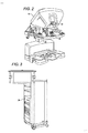
- FIG. 1 is a plan view illustration of a Minimally Invasive Robotic Surgical (MIRS) system 10, typically used for performing a minimally invasive diagnostic or surgical procedure on a Patient 12 who is lying down on an Operating table 14.
- the system can include a Surgeon's Console 16 for use by a Surgeon 18 during the procedure.
- One or more Assistants 20 may also participate in the procedure.
- the MIRS system 10 can further include a Patient Side Cart 22 (surgical robot) and an Electronics Cart 24.
- the Patient Side Cart 22 can manipulate at least one removably coupled tool assembly 26 (hereinafter simply referred to as a "tool") through a minimally invasive incision in the body of the Patient 12 while the Surgeon 18 views the surgical site through the Console 16.
- An image of the surgical site can be obtained by an endoscope 28, such as a stereoscopic endoscope, which can be manipulated by the Patient Side Cart 22 to orient the endoscope 28.
- the Electronics Cart 24 can be used to process the images of the surgical site for subsequent display to the Surgeon 18 through the Surgeon's Console 16.
- the number of surgical tools 26 used at one time will generally depend on the diagnostic or surgical procedure and the space constraints within the operating room among other factors. If it is necessary to change one or more of the tools 26 being used during a procedure, an Assistant 20 may remove the tool 26 from the Patient Side Cart 22, and replace it with another tool 26 from a tray 30 in the operating room.
- FIG. 2 is a perspective view of the Surgeon's Console 16.
- the Surgeon's Console 16 includes a left eye display 32 and a right eye display 34 for presenting the Surgeon 18 with a coordinated stereo view of the surgical site that enables depth perception.
- the Console 16 further includes one or more input control devices 36, which in turn cause the Patient Side Cart 22 (shown in FIG. 1 ) to manipulate one or more tools.
- the input control devices 36 can provide the same degrees of freedom as their associated tools 26 (shown in FIG. 1 ) to provide the Surgeon with telepresence, or the perception that the input control devices 36 are integral with the tools 26 so that the Surgeon has a strong sense of directly controlling the tools 26.
- position, force, and tactile feedback sensors may be employed to transmit position, force, and tactile sensations from the tools 26 back to the Surgeon's hands through the input control devices 36.
- the Surgeon's Console 16 is usually located in the same room as the patient so that the Surgeon may directly monitor the procedure, be physically present if necessary, and speak to an Assistant directly rather than over the telephone or other communication medium. However, the Surgeon can be located in a different room, a completely different building, or other remote location from the Patient allowing for remote surgical procedures.
- FIG. 3 is a perspective view of the Electronics Cart 24.
- the Electronics Cart 24 can be coupled with the endoscope 28 and can include a processor to process captured images for subsequent display, such as to a Surgeon on the Surgeon's Console, or on another suitable display located locally and/or remotely.
- the Electronics Cart 24 can process the captured images to present the Surgeon with coordinated stereo images of the surgical site.
- Such coordination can include alignment between the opposing images and can include adjusting the stereo working distance of the stereoscopic endoscope.
- image processing can include the use of previously determined camera calibration parameters to compensate for imaging errors of the image capture device, such as optical aberrations.
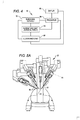
- FIG. 4 diagrammatically illustrates a robotic surgery system 50 (such as MIRS system 10 of FIG. 1 ).
- a Surgeon's Console 52 (such as Surgeon's Console 16 in FIG. 1 ) can be used by a Surgeon to control a Patient Side Cart (Surgical Robot) 54 (such as Patent Side Cart 22 in FIG. 1 ) during a minimally invasive procedure.
- the Patient Side Cart 54 can use an imaging device, such as a stereoscopic endoscope, to capture images of the procedure site and output the captured images to an Electronics Cart 56 (such as the Electronics Cart 24 in FIG. 1 ).
- the Electronics Cart 56 can process the captured images in a variety of ways prior to any subsequent display.
- the Electronics Cart 56 can overlay the captured images with a virtual control interface prior to displaying the combined images to the Surgeon via the Surgeon's Console 52.
- the Patient Side Cart 54 can output the captured images for processing outside the Electronics Cart 56.
- the Patient Side Cart 54 can output the captured images to a processor 58, which can be used to process the captured images.
- the images can also be processed by a combination the Electronics Cart 56 and the processor 58, which can be coupled together to process the captured images jointly, sequentially, and/or combinations thereof.
- One or more separate displays 60 can also be coupled with the processor 58 and/or the Electronics Cart 56 for local and/or remote display of images, such as images of the procedure site, or other related images.
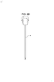
- FIGS. 5A and 5B show a Patient Side Cart 22 and a surgical tool 62, respectively.
- the surgical tool 62 is an example of the surgical tools 26.
- the Patient Side Cart 22 shown provides for the manipulation of three surgical tools 26 and an imaging device 28, such as a stereoscopic endoscope used for the capture of images of the site of the procedure. Manipulation is provided by robotic mechanisms having a number of robotic joints.
- the imaging device 28 and the surgical tools 26 can be positioned and manipulated through incisions in the patient so that a kinematic remote center is maintained at the incision to minimize the size of the incision.
- Images of the surgical site can include images of the distal ends of the surgical tools 26 when they are positioned within the field-of-view of the imaging device 28.
- Each tool 26 is detachable from and carried by a respective surgical manipulator 31, which is located at the distal end of one or more of the robotic joints.
- the surgical manipulator 31 provides a moveable platform for moving the entirety of a tool 26 with respect to the Patient Side Cart 22, via movement of the robotic joints.
- the surgical manipulator 31 also provides power to operate the tool 26 using one or more mechanical and/or electrical interfaces.
- An example of such a carriage assembly is found at U.S. Patent Publication No. US 2013/0325034 , (Atty. Docket No. ISRG04330/US).
- FIG. 6 is a simplified schematic diagram of a telesurgically controlled surgery system surgical system 100.
- the surgical system 100 includes a surgeon console 102, which for example can be the Surgeon's Console 52.
- the surgeon console 102 drives a patient side cart 104, which for example can be the Patient Side Cart 22.
- the patient side cart 104 includes a surgical manipulator 106, which for example can be the surgical manipulator 31.
- the surgical manipulator 106 includes a motor unit 108 and a surgical tool 110.
- the motor unit 108 is a carriage assembly that holds 5 motors. In some embodiments only 5 motors are used, while in other embodiments more or less than 5 motors can be used.
- the motor unit 108 includes a plurality of motors, which can be assigned to different mechanisms.
- the motor unit 108 includes a power motor 112, camshaft motor 114, pitch motor 116, yaw motor 118, and low-force grip motor 120, although these motors can be used for different purposes depending on the attached instrument.
- each motor is an electric motor that mechanically and electrically couples with corresponding inputs of the surgical tool 110.
- the motor unit 108 may be located at a proximal end of the surgical tool 110 in a shared chassis with the surgical tool, as generally depicted by the proximal housing shown at FIG. 5B .
- the tool 110 for example, can be the tool 26 described above.
- An example of a tool usable as tool 110 is at Int'l. Pub. No. WO 2011/060318 (Attorney Docket No.: ISRG02360/PCT).
- the tool 110 is an elongated effector unit 122 that includes three discrete inputs that each mechanically couple with the pitch motor 116, yaw motor 118, and a low-force grip motor 120 by way of the surgical manipulator 106.
- the tool 110 also includes a transmission 124, which mechanically couples with the power motor 112 and the camshaft motor 114.
- a surgical end effector 126 is located at the distal end of the effector unit 122.
- the surgical end effector 126 and effector unit 122 are connected by way of a moveable wrist.
- An example of such a wrist is shown at U.S. Patent Publication No. US 2011/0118709 (Attorney Docket No. ISRG02350/US).
- the surgical end effector can be characterized by a plurality of discrete but interrelated mechanisms, with each mechanism providing a degree of freedom (DOF) for the surgical end effector 126.
- DOF degree of freedom
- a DOF is one or more interrelated mechanisms for affecting a corresponding movement.
- the DOFs endow the surgical end effector 126 with different modes of operation that can operate concurrently or discretely.
- the wrist enables the surgical end effector 126 to pitch and yaw with respect to the surgical manipulator 106, and accordingly includes a pitch DOF 128 and a yaw DOF 130.
- the surgical end effector 126 also includes a roll DOF 132 rotating surgical end effector about an elongated axis.
- the surgical end effector 126 may include a clamping and cutting mechanism, such as a surgical stapler.
- a clamping mechanism such as a surgical stapler.
- An example of such a clamping mechanism is shown at U.S. Patent Publication No. 2011-0118778 A1 , (Attorney Docket No. ISRG02330/US).
- the clamping mechanism can grip according to two modes, and accordingly includes two DOFs.
- a low-force DOF 132 e.g., a cable actuated mechanism
- the low-force DOF 132 is useful for staging the surgical end effector for a cutting or stapling operation.
- a high-force DOF 134 (e.g., a lead screw actuated mechanism) operates to further open the clamp or close the clamp onto tissue with relatively high force, for example, to tourniquet tissue in preparation for a cutting or stapling operation.
- the surgical end effector 126 employs a tool actuation DOF 138 to further affect the tissue, for example a stapling, cutting, and/or cauterizing device.
- each of the pitch DOF 128, yaw DOF 130, and low force grip DOF 139 is discretely paired with a motor, and can operate independently and concurrently with respect to other DOFs.
- the high force DOF 126, roll DOF 132, and tool actuation DOF 138 share a single input with the power motor 112, via the transmission. Accordingly, only one of the high force DOF 126, roll DOF 132, and tool actuation DOF 138 can operate at one time, since coupling with the power motor 112 occurs discretely.
- the camshaft motor 114 is actuated to shift output of the power motor 112 between the high force DOF 126, roll DOF 132, and tool actuation DOF 138. Accordingly, the transmission 124 advantageously allows a greater amount of DOFs than an arrangement where each motor is dedicated to a single DOF.
- Embodiments of invention relate to a system and an exemplary method, not forming part of the invention, to control the 6 degrees of freedom (6 DOFs) of a stapler instrument with the 5 inputs allowable from a motor carriage. It takes one of the five inputs to use as a shifter, which then allows another input to be selectively engaged to three different stapler DOFs.
- the six DOFs of a stapler instrument can include wrist roll, wrist pitch, wrist yaw, low-force grip (toggle), high-force grip (clamp), and tool actuation (stapler fire). Wrist pitch, yaw, and low-force grip may be cable actuated, while roll, clamp, and fire are driven by independent sets of coaxial gears.
- the transmission can include three main modes: roll, clamp/unclamp, and fire. Wrist rotation, pitch, yaw, and low-force grip are all under active servo control, and the high-force grip and fire DOFS are coupled to the roll axis.
- the driven input is selectively coupled to wrist roll, clamp, and/or fire. This is done through the use of idler gears that can be rotated in and out of engagement with the appropriate stapler DOF. Additionally, there is a method to lock each DOF to ground through the use of a lever arm. These lever arms are controlled by the shifting input, which can be a camshaft with the appropriate number and shapes of lobes. During a roll movement of the wrist, it is necessary for the clamp and fire input rings to rotate along with the roll gear. Because of this constraint, the gear ratios between the instrument input and the input rings and roll gear are all the same.
- the system can be configured so that all transitions move only one function at a time. This way all transitions are testable for safety.
- the roll gear is locked. To avoid the necessity of the wrist needing to be positioned such that the roll gear is aligned with the teeth of the locking arm, there is a secondary friction lock on this DOF.
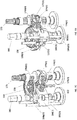
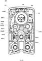
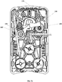
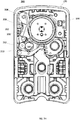
- FIGS. 7A through 7H respectively show perspective and cross-sections of a transmission assembly 140.
- the transmission includes a gear train for each of the high force DOF 126, roll DOF 132, and tool actuation DOF 138.
- a first gear train 142 is located at the proximal end of the transmission assembly 140.
- the first gear train 142 drives the roll DOF 132 by axially rotating a main shaft 144.
- the main shaft 144 includes an axial passageway 146 for routing control cables to the surgical end effector 126.
- the main shaft 144 is directly rotated by driving external gear teeth 147 of a proximal gear 148.
- a second gear train 150 is located directly adjacent to the first gear train 142, at a mid-portion of the transmission assembly 140.
- the second gear train 150 drives the high force grip DOF 126 by rotation of a middle shaft 152 with respect to the main shaft 144.
- the middle shaft 152 is held by the main shaft 144 and accordingly is rotated with the main shaft 144. Put another way, the axis of rotation of the middle shaft 152 can orbit about the axis of rotation of the main shaft 144.
- the middle shaft 152 is directly connected to a middle internal gear 154, which in turn is driven by internal gear teeth (not shown in this view) of a middle gear 156.
- the middle gear 156 also includes external gear teeth 158 for directly driving the middle gear 156, ultimately by way of the power motor 112.
- the external gear teeth 158 of the middle gear 156 are configured identically to the external gear teeth 147 of the proximal gear 148. Accordingly, if driven synchronously, assuming identical input gears, there is no relative movement between the middle gear 156 and the proximal gear 148, and accordingly the middle shaft 152 is not driven with respect to main shaft 144.
- the middle gear 156 (together with a distal gear 166 described below) can be configured to synchronously rotate with the main shaft 144 when both the middle gear 156 and are and proximal gear 148 are synchronously engaged with the power motor 112.
- rotation of the middle gear 156 does not result in rotation of the middle internal gear 154, since the middle gear 156 is not allowed to roll with respect to the main shaft 144.
- the middle gear 156 clocks with the main shaft 144, and thus cannot move asynchronously with respect to the main shaft 144 to move the middle shaft 152.
- the second gear train 150 includes a second disengaged state, in which the middle gear 156 is physically disengaged from the power motor 112 and physically locked, and thereby cannot rotate cannot drive the middle internal gear 154.
- the proximal gear 148 and main shaft 144 are locked and therefore cannot rotate.
- the axis of rotation of the middle internal gear 154 cannot orbit about the axis of rotation of the main shaft 144.
- the middle internal gear 154 can spin about its own axis of rotation. Accordingly, in the engaged state, the middle gear 156 rotates with respect to the main shaft 144, and thereby drives the middle internal gear 154, ultimately by way of the power motor 112.
- a third gear train 160 is located at a distal portion of the transmission assembly 140, and is largely configured in the same manner as the second gear train 150.
- the third gear train 160 drives the tool actuation DOF 138 by rotation of a distal shaft 162 with respect to the main shaft 144.
- the distal shaft 162 is held by the main shaft 144 and accordingly rotates with the main shaft 144.
- the axis of rotation of the distal shaft 162 can orbit about the axis of rotation of the main shaft 144.
- the distal shaft 162 is directly connected to a distal internal gear 164, which in turn is driven by internal gear teeth (not shown in this view) of a distal gear 166.
- the distal gear 166 also includes external gear teeth 168 for directly driving the distal gear 166, ultimately by way of the power motor 112.
- the external teeth 168 of the distal gear 162 are configured in the same manner as the external gear teeth 147 of the proximal gear 148, as well as the external gear teeth 158 of the middle gear 156. Accordingly, when driven synchronously, there is no relative movement between the distal gear 166, middle gear 156 and proximal gear 148.
- an external portion of the main shaft 144 holds the distal gear 166 by way of two bearings.
- the distal gear 166 (together with the middle gear 156) can be configured to synchronously rotate with the main shaft 144 when both the distal gear 166 and are and proximal gear 148 are synchronously engaged with the power motor 112.
- rotation of the distal gear 166 does not result in rotation of the distal internal gear 164, since the distal gear 166 is not allowed to roll with respect to the main shaft 144.
- the distal gear 166 clocks with the main shaft 144, and thus cannot move asynchronously with respect to the main shaft 144 to move the distal shaft 162.
- the third gear train 160 includes a second disengaged state, in which the distal gear 166 is physically disengaged from the power motor 112 and physically locked, and thereby cannot rotate cannot drive the distal internal gear 164.
- the proximal gear 148 and main shaft 144 are locked and therefore cannot rotate.
- the axis of rotation of the distal internal gear 164 cannot orbit about the axis of rotation of the main shaft 144.
- the distal internal gear 164 can spin about its own axis of rotation. Accordingly, in the engaged state, the distal gear 166 rotates with respect to the main shaft 144, and thereby drives the distal internal gear 164, ultimately by way of the power motor 112.
- FIGS. 7B-D a representative cross section and perspective views of the second gear train 150 is shown.
- FIGS. 7C and 7D have portions of the other gear trains removed to allow greater understanding of how a single gear train is configured.
- the first gear train 142 and third gear train 160 are configured in the same manner, accordingly, the following description applies in kind to FIGS. 7E and 7F , which respectively show representative cross-sections of those gear trains.
- FIGS. 7E and 7F which respectively show representative cross-sections of those gear trains.
- common numbering for similar parts between the gear trains is used.
- locker arm 188(II) refers to the locker arm of the second gear train 150
- locker arm 188(III) refers to the locker arm of the third gear train.
- Each gear train operates essentially in the same manner, however, according to differing timing as determined by respective cam lobes of a shared camshaft as described below.
- a greater housing 170 of the surgical tool 110 holds the transmission assembly 140.
- the power motor 112 drives a first input gear 172(II) via input shaft 173, as shown at FIGS. 7C and 7D , which is shared for each of the gear trains.
- the first input gear 172(II) is meshed with an idler gear 174(11), which in turn meshes with a second input gear 176(II) that can mesh with the middle gear 156.
- the idler gear 174(II) and second input gear 176(II) are on an arm 177(II), as shown at FIGS. 7C and 7D , that rotates about the first input gear 172(II).
- the second input gear 176(II) is positioned at the downward portion of the arc, and thereby is not meshed with the middle gear 156.
- the second input gear 176(II) can be moved to engage the second input gear 176(II) with the middle gear 156.
- a compression spring (not shown) is loaded between the second input gear shaft and housing 170 to bias the second input gear 176(II) towards the middle gear 156 such that middle gear 156 is engaged to power motor 112.
- a camshaft 180 is disposed along the gear trains.
- the camshaft 180 generally includes at least two cam lobes per drive chain. The lobes rotate to engage and disengage a DOF mechanism with a gear train.
- the camshaft 180 is rotated by the camshaft motor 114 to selectively place the cam lobes into desired positions.
- a first cam lobe 182(II) rotates to engage a bearing 183(II) of a rocker arm 184(II).
- the rocker arm 184(II) is moveable about a rocker pivot 184p(II).
- the rocker arm 184(II) extends to engage a gear shaft 176S(II), as shown at FIGS. 7C and 7D , of the second input gear 176(II).
- the second input gear 176(II) is engaged with the middle gear 156 as shown, due to the bias of the compression spring (not shown).
- a second cam lobe 186(II) rotates to engage a surface 187(II) of a locker arm 188(II), which pivots about locker arm pivot 190(II).
- the locker arm 188(II) includes a toothed portion 192(II) that can be moved to mesh the toothed portion 192(II) with the middle gear 156.
- a spring 157 is loaded between the locker arm 188(II) and housing 170 to bias the toothed portion 192(II) away from the middle gear 156.
- a manual unclamp feature is provided. In some embodiments, this can be accomplished by the user manually rotating the camshaft 180 to the high force grip DOF state, as described below. As shown at FIG. 7G , an interlock cam lobe 194 of camshaft 180 is moveable to a high state to move an interlock flag 196 that is rotatable and connected to a one-way clutch 198, which ultimately interfaces with the middle shaft 152. The end of the one-way clutch 198 is accessible by a handheld tool, such as a wrench, through a passage in the housing 170.
- the interlock flag 196 blocks the passage unless a high portion of the interlock cam lobe 194 is lifting the interlock flag 196 as shown.
- the interlock flag 196 provides the user access to drive the middle shaft 152 via the one-way clutch 198 in a direction that only allows for the jaws to be unclamped.
- FIG. 7H depicts a friction lock mechanism 200, which acts as a secondary shaft braking system with respect to the locker arms 188(I-III).
- a friction lock arm 202 pivots about a pivot 204 and includes a brake surface 206.
- the friction lock arm 202 is biased by a spring 208 to place the brake surface 206 against a portion of shaft 144, as shown. In this position, the shaft 144 cannot roll.
- a friction lock cam lobe 210 of the camshaft 180 includes a high portion and a low portion. The shaft 144 will remain braked as long as the low portion of the friction lock cam lobe 210 is against a bearing 212 that positioned on the friction lock arm 202. The high portion can be rotated to lift a bearing 212 to position the friction lock arm away from the shaft 144. In that position, the shaft 144 is allowed to roll.
- the toothed portion 192(I-III) is moved to engage the respective proximal gear 148, middle gear 156, or distal gear 166.
- This position locks the middle gear 156 with the locker arm 188, and accordingly, the middle gear 156 cannot move.
- One purpose of locking the middle gear 156 is to lock the last position of the high force grip DOF into a locked state. Generally, each gear train is locked in a similar manner, thus preventing unwanted movement.
- the camshaft 180 is configured to operate the gear trains in harmony, which is achieved through camshaft timing.
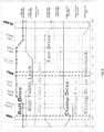
- FIG. 8 shows a cam state chart for operation of the transmission 140.
- the gear trains share a common camshaft, which for example is the camshaft 180 shown in FIGS. 7B-7D .
- the camshaft 180 provides each gear train with at least two lobes, e.g., the first cam lobe 182(I-III) and second cam lobe 186(I-III) operate with the first, second and third gear trains.
- some gear trains can include more lobes.
- the first gear train includes a third lobe to operate a friction lock.
- additional lobes can be included as safely mechanisms to back drive DOFs in case of a system failure.
- each gear train is operated by a power cam and a locker cam.
- each cam has a low state and a high state, with transitions ramps in between. The duration of each low and high state is based on the desired duration of operation of an object being lifted (e.g., the locker arm 188(I-III) and the rocker arm 184(I-III).
- a high state of the first cam lobe 182(I-III) means that the first cam lobe 182(I-III) is positioned such that an associated gear train is engaged with the power motor 112, while a low state of the first cam lobe 182(I-III) means disengagement.
- a high state of the second cam lobe 186(I-III) means that the second cam lobe 186(I-III) is positioned such that an associated gear train is engaged with an associated locker arm 188(I-III), while a low state of the second cam lobe 186(I-III) means disengagement.
- the outputs of the middle and distal gear trains not necessarily tied to the DOFs shown, and hence are interchangeable.
- the cam state chart shows the low and high state for each cam over 360 degrees of rotation.
- the transmission 140 is configured to supply power for operation of the roll DOF 132 (ROLL).
- cam lobes 182(I-III) for each gear train is at a high state and cam lobes 186(I-III) for each gear train is at a low state.
- the first gear train 142 is unlocked and engaged with the power motor 112.
- the locker arm 188(1) of the first gear train 142 is disengaged from the proximal gear 148 and the second input gear is engaged with the proximal gear 148.
- the second gear train 150 and the third gear train 160 are also unlocked, and the middle gear 156 and distal gear 166 remain in contact with the power motor.
- the friction cam lobe 210 for actuating the friction lock arm 202 is driven to a low state to allow the shaft 144 to turn.
- the middle gear 156 and distal gear 166 are required to rotate in sync with the proximal gear 148, since the middle internal gear 154 and distal internal gear 164 are held within and rotate with the shaft 144. In this manner, relative movement is avoided between the middle gear 156/middle internal gear 154 and the distal gear 166/distal internal gear 164, thereby preventing operation of the middle shaft 152 and distal shaft 162. Accordingly, although the middle gear 156 and distal gear 166 remain engaged with the power motor 112 and thus are turned during a roll operation, the second gear train 150 and the third gear train 160 do not operate respective DOFs.
- an "in cannula brake check” can be performed at approximately 40 degrees of rotation of the camshaft 180.
- the friction lock arm 202 remains engaged with the shaft 144 but the locker arm 188(1) of the first gear train becomes disengaged, while the first gear train 142 remains engaged with the power motor 112. Because the locker arm 188(1) is disengaged, this allows the system to self-test the friction lock mechanism 200 by attempting to roll the braked shaft 144. If the shaft 144 is able to roll in this condition, it may be indicative that the friction lock mechanism 200 is malfunctioning.
- the transmission is shifted to provide power to the tool actuation DOF 138 (FIRE).
- the first cam lobe 182(I) of the first gear train 142 and the first cam lobe 182(III) of the third gear train 160 are at lows states and the first cam lobe 182(II) of the second gear train 150 is high.
- the second input gears of the first gear train 142 and the third gear train 160 are respectively disengaged from the proximal gear 148 and the distal gear 166, while the second input gear of the second gear train 150 is engaged with the middle gear 156.
- the middle gear 156 receives power from the power motor 112.
- the second cam lobe 186(1) of the first gear train 142 and the second cam lobe 186(III) of the third gear train 160 are at high states, and the second cam lobe 186(II) of of the second gear train 150 is at a low state.
- the locker arm 188(1) of the first gear train 142 and the locker arm 188(III) of the third gear train 160 are respectively engaged with the proximal gear 148 and the distal gear 166, while the locker arm 188(II) of the second gear train 150 is disengaged from the middle gear 156.
- the middle gear 156 is free to turn.
- the transmission is configured to provide power to the high force grip DOF 136 (CLAMP).
- CLAMP high force grip DOF 136
- the first cam lobe 182(1) of the first gear train 142 and the first cam lobe 182(II) of the second gear train 150 are at low states and the first cam lobe 182(III) of the third gear train 160 is at a high state.
- the second input gears of the first gear train 142 and the second gear train 150 are respectively disengaged from the proximal gear 148 and the middle gear 156, while the second input gear of the second gear train 150 is engaged with the middle gear 156.
- the distal gear 166 receives power from the power motor 112.
- the second cam lobe 186(1) of the first gear train 142 and the second cam lobe 186(II) of second gear train 150 are at high states and the second cam lobe 186(III) of the third gear train 160 is at a low state.
- the locker arm 188(1) of the first gear train 142 and the locker arm 188(II) of the second gear train 150 are respectively engaged with the proximal gear 148 and the distal gear 156, while the locker arm 188(III) of the third gear train 160 is disengaged from the distal gear 166.
- the interlock cam lobe 194 is driven to a high state, as described above with reference to FIG. 7G . This moves the interlock flag 196, and allows the user access to manually back drive the second gear train in case of a system failure.
Description
- Minimally invasive medical techniques are intended to reduce the amount of extraneous tissue that is damaged during diagnostic or surgical procedures, thereby reducing patient recovery time, discomfort, and deleterious side effects. One effect of minimally invasive surgery, for example, is reduced post-operative hospital recovery times. Because the average hospital stay for a standard surgery is typically significantly longer than the average stay for an analogous minimally invasive surgery, increased use of minimally invasive techniques could save millions of dollars in hospital costs each year. While many of the surgeries performed each year in the United States could potentially be performed in a minimally invasive manner, only a portion of the current surgeries use these advantageous techniques due to limitations in minimally invasive surgical instruments and the additional surgical training involved in mastering them.
- Minimally invasive telesurgical systems have been developed to increase a surgeon's dexterity and avoid some of the limitations on traditional minimally invasive techniques. In telesurgery, the surgeon uses some form of remote control (e.g., a servomechanism or the like) to manipulate surgical instrument movements, rather than directly holding and moving the instruments by hand. In telesurgery systems, the surgeon can be provided with an image of the surgical site at a surgical workstation. While viewing a two or three dimensional image of the surgical site on a display, the surgeon performs the surgical procedures on the patient by manipulating master control devices, which in turn control motion of the servo-mechanically operated instruments.
- The servomechanism used for telesurgery will often accept input from two master controllers (one for each of the surgeon's hands) and may include two or more robotic arms on each of which a surgical instrument is mounted. Operative communication between master controllers and associated robotic arm and instrument assemblies is typically achieved through a control system. The control system typically includes at least one processor that relays input commands from the master controllers to the associated robotic arm and instrument assemblies and back from the instrument and arm assemblies to the associated master controllers in the case of, for example, force feedback or the like. One example of a robotic surgical system is the DA VINCI® system available from Intuitive Surgical, Inc. of Sunnyvale, California, USA.
- A variety of structural arrangements can be used to support the surgical instrument at the surgical site during robotic surgery. The driven linkage or "slave" is often called a robotic surgical manipulator, and exemplary linkage arrangements for use as a robotic surgical manipulator during minimally invasive robotic surgery are described in
U.S. Pat. Nos. 7,594,912 ;6,758,843 ;6,246,200 ; and5,800,423 . These linkages often make use of a parallelogram arrangement to hold an instrument having a shaft. Such a manipulator structure can constrain movement of the instrument so that the instrument pivots about a remote center of manipulation positioned in space along the length of the rigid shaft. By aligning the remote center of manipulation with the incision point to the internal surgical site (for example, with a trocar or cannula at an abdominal wall during laparoscopic surgery), an end effector of the surgical instrument can be positioned safely by moving the proximal end of the shaft using the manipulator linkage without imposing potentially dangerous forces against the abdominal wall. Alternative manipulator structures are described, for example, inU.S. Pat. Nos. 7,763,015 ;6,702,805 ;6,676,669 ;5,855,583 ;5,808,665 ;5,445,166 ; and5,184,601 . - A variety of structural arrangements can also be used to support and position the robotic surgical manipulator and the surgical instrument at the surgical site during robotic surgery. Supporting linkage mechanisms, sometimes referred to as set-up joints, or set-up joint arms, are often used to position and align each manipulator with the respective incision point in a patient's body. The supporting linkage mechanism facilitates the alignment of a surgical manipulator with a desired surgical incision point and targeted anatomy. Exemplary supporting linkage mechanisms are described in
U.S. Pat. Nos. 6,246,200 and6,788,018 . - While the new telesurgical systems and devices have proven highly effective and advantageous, still further improvements are desirable. In general, improved minimally invasive robotic surgery systems are desirable. Often, new surgical instruments are developed for use on existing telesurgical system platforms. Thus, the instrument is required to adapt to the telesurgical system, since development of a new telesurgical system for a particular surgical application is cost prohibitive. However, issues arise when existing telesurgical platforms do not have the required amount of motor outputs for all of the mechanisms of a particular surgical instrument. Thus, there is a need to adapt new surgical devices to existing telesurgical systems without limiting the surgical capabilities and without requiring modification to the existing telesurgical systems.
-
US 2011/290856 discloses a surgical instrument. Various examples of the surgical instrument include an end effector that has a moveable cutting implement. A main drive shaft assembly operably interfaces with the end effector for transmitting an actuation motion to the movable cutting implement therein. A gear drive train is connected to the main drive shaft assembly. The gear drive train is actuated by a motor that is configured to receive control signals from a robotic system. - The present invention provides a surgical tool as set out in the appended claims. Many embodiments are directed to a surgical tool comprising an elongated shaft having a proximal end and distal end. A surgical end effector is located about the distal end. The surgical end effector may include a plurality of effector mechanisms, each effector mechanism having one or a plurality of degree of freedoms (DOFs). An effector body may also be located at the proximal end. The effector body may include a plurality of motor interfaces for driving the plurality of effector mechanisms. For example, the plurality of motor interfaces may include a first motor interface. A transmission may be coupled between the effector body and the surgical end effector. The transmission may be configured to shift coupling of the first motor interface between only a portion of the plurality of effector mechanisms and associated DOFs.
- Many embodiments are directed to a surgical tool comprising an elongated shaft having a proximal end and distal end. A surgical end effector is located at the distal end of the shaft. The surgical end effector has a plurality of end effector components each associated with a unique mechanical degree of freedom. The plurality of end effector components has a first end effector component and a second end effector component. A drive mechanism is located at the proximal end of the shaft. The drive mechanism has a first motor interface and a transmission. The transmission includes a shift mechanism movable between a first state and a second state. In the first state the first motor interface is coupled via the transmission to drive the first end effector component without driving the second end effector component. In the second state the first motor interface being coupled via the transmission to drive the second end effector component without driving the first end effector component, wherein the shift mechanism includes a rotatable camshaft (180) comprising a plurality of camshaft lobes that comprise a pair of lobes for powering and locking in each of the first state and the second state, and wherein a first position of the rotatable camshaft corresponds to the first state and a second position of the rotatable camshaft corresponds to the second state.
- In many embodiments, the drive mechanism includes a second motor interface coupled to shift the shift mechanism between the first state and the second state.
- In many embodiments, the plurality of end effector components comprises a third end effector component; the shift mechanism is movable to a third state, in the first state and in the second state the first motor interface not driving the third end effector component, and in the third state the first motor interface being coupled via the transmission to drive the third end effector component without driving the first and second end effector components.
- In many embodiments, the drive mechanism includes a second motor interface coupled to shift the shift mechanism between the first state, the second state, and the third state.
- In many embodiments, the first end effector component may be associated with a first end effector mechanical degree of freedom, and the second end effector component is associated with a second end effector mechanical degree of freedom. The drive mechanism may include a second motor interface coupled to drive a third end effector mechanical degree of freedom, a third motor interface coupled to drive a fourth end effector mechanical degree of freedom, and a fourth motor interface coupled to drive a fifth end effector mechanical degree of freedom. The first, second, third, fourth, and fifth mechanical degrees of freedom of the end effector are each unique.
- In many embodiments, the plurality of end effector components includes a third end effector component associated with a sixth end effector mechanical degree of freedom. The first, second, third, fourth, fifth, and sixth mechanical degrees of freedom of the end effector are each unique.
- In many embodiments, the drive mechanism includes a fifth motor interface coupled to shift the shift mechanism between the first state and the second state.
- In many embodiments, the shift mechanism may include a rotatable camshaft, where a first position of the camshaft corresponding to the first state, and a second position of the camshaft corresponding to the second state.
- In many embodiments, the drive mechanism further includes a second motor interface coupled to drive the camshaft.
- In many embodiments, the transmission may include a rotatable camshaft. The camshaft can include a first camshaft position for shifting coupling of the first motor interface to a first DOF of the plurality of DOFs; a second camshaft position for shifting coupling of the first motor interface to a second DOF of the plurality of DOFs; and a third camshaft position for shifting coupling of the first motor interface to a third DOF of the plurality of DOFs.
- In many embodiments, the drive mechanism further includes a second, third, fourth, and fifth motor interface, wherein the camshaft is driven by the second motor interface.
- In many embodiments, the plurality of DOFs further includes a fourth DOF coupled exclusively with the third motor interface; a fifth DOF coupled exclusively with the fourth motor interface; and a sixth DOF coupled exclusively with the fifth motor interface.
- In many embodiment, the surgical end effector can include a gripping device having a surgical tool, wherein the surgical end effector includes a wrist, the wrist being able to pitch, yaw, and roll the gripping device with respect to a remotely controlled arm.
- In many embodiments, the first DOF is a mechanism for rolling the wrist; the second DOF is a mechanism for actuating the surgical tool; the third DOF is a mechanism for actuating the gripping device with high force relative to the sixth DOF; the fourth DOF is a mechanism for causing the wrist to yaw; the fifth DOF is a mechanism for causing the wrist to pitch; and the sixth DOF is a mechanism for actuating the gripping device with low force relative to the third DOF.
- In many embodiments, the camshaft includes a plurality of camshaft lobes.
- In many embodiments, the plurality of camshaft lobes includes a pair of lobes for powering and locking each of the first, second, and third DOFs.
- In many embodiments, the transmission includes a first gear train for driving the first DOF, a second gear train for driving the second DOF, and a third gear train for driving the third DOF.
- In many embodiments, the first gear train includes a first input gear; a first output gear ultimately coupled with the first input gear; a first rocker arm moveably engaged with the camshaft for engaging and disengaging the first input gear with the first output gear; a first locker arm moveably engaged with the camshaft for locking and unlocking the first output gear.
- In many embodiments, the second gear train includes a second input gear; a second output gear ultimately coupled with the second input gear; a second rocker arm moveably engaged with the camshaft for engaging and disengaging the second input gear with the second output gear; and a second locker arm moveably engaged with the camshaft for locking and unlocking the second output gear.
- In many embodiments, the third gear train includes a third input gear; a third output gear ultimately coupled with the third input gear; a third rocker arm moveably engaged with the camshaft for engaging and disengaging the third input gear with the third output gear; a third locker arm moveably engaged with the camshaft for locking and unlocking the third output gear.
- In many embodiments, the first output gear may be coupled to a main shaft extending along and rotatable about an axis, and wherein the second and third output gears are held within the main shaft and rotate with the main shaft about the axis.
- In many embodiments, the second output gear may be coupled to an first output shaft that extends within the main shaft, and the third output gear may be coupled to an second output shaft that extends within the main shaft.
- In many embodiments, the first, second, and third gear trains may be arranged along a common axis that is parallel with the camshaft.
- Many examples, not part of the invention, are directed to a method for shifting a transmission of a remotely controlled surgical apparatus. In the method, a transmission of a surgical device is shifted to engage one of a plurality of shiftable effector outputs to a surgical end effector of the surgical device. The surgical device may include a plurality of non-shiftable outputs. The surgical device may be connected to a remote controlled arm. The remote controlled arm may have a plurality of motors including a first motor for driving the transmission and a plurality of dedicated motors for driving the plurality of non-shiftable outputs. The one engaged shiftable effector output can be driven with the first motor to drive a corresponding effector mechanism of the surgical end effector.
- Many examples, not part of the invention, are directed to a method in a surgical device comprising at least one of a first motor interface, a transmission, and an end effector comprising a first and a second component. The method includes operating the transmission in a first state, shifting the transmission from the first state to a second state, operating the transmission in the second state. and shifting the transmission from the second state to the first state. In the first state, the transmission couples the first motor interface to the first component of the end effector and decouples the first motor interface from the second component of the end effector. In the second state, the transmission couples the first motor interface with the second component of the end effector and decouples the first motor interface from the first component of the end effector.
- In many embodiments, at least one of the plurality of non-shiftable effector outputs of the surgical end effector may be driven using a dedicated motor.
- In many embodiments, shifting the transmission is caused by driving a camshaft of the transmission using a second motor.
- In many embodiments, driving the camshaft is caused by rotating the camshaft to sequentially engage one of a plurality of gear trains.
- In many embodiments, the camshaft is rotated to move a plurality of rocker arms that engage a plurality of gear trains of the transmission.
- In many embodiments, rotating the camshaft causes at least one of the non-engaged gear trains to become locked.
- In many embodiments, shifting can only occur sequentially along the plurality of gear trains.
- In many embodiments, the plurality of effector shiftable outputs includes a first shiftable output for actuating the roll DOF, and high force grip DOF, and a tool actuation DOF.
- In many embodiments, the wherein the plurality of dedicated DOFs comprises a yaw DOF, pitch DOF, and a low force grip DOF.
-
-
FIG. 1 is a plan view of a minimally invasive telesurgically controlled surgery system being used to perform a surgery, in accordance with many embodiments. -
FIG. 2 is a perspective view of a surgeon's control console for a telesurgically controlled surgery system, in accordance with many embodiments. -
FIG. 3 is a perspective view of a telesurgically controlled surgery system electronics cart, in accordance with many embodiments. -
FIG. 4 diagrammatically illustrates a telesurgically controlled surgery system, in accordance with many embodiments. -
FIG. 5A is a partial view of a patient side cart of a telesurgically controlled surgery system, in accordance with many embodiments. -
FIG. 5B is a front view of a telesurgically operated surgery tool, in accordance with many embodiments. -
FIG. 6 is a simplified schematic diagram of a telesurgically controlled surgery system surgical system, in accordance with many embodiments. -
FIGS. 7A-7H are longitudinal and axial cross-sections of a transmission assembly of a telesurgically operated surgery tool, in accordance with many embodiments. -
FIG. 8 shows a cam state chart for operation of the of a transmission assembly of a telesurgically operated surgery tool, in accordance with many embodiments. - In the following description, various embodiments of the present invention will be described. For purposes of explanation, specific configurations and details are set forth in order to provide a thorough understanding of the embodiments. However, it will also be apparent to one skilled in the art that the present invention may be practiced without the specific details. Furthermore, well-known features may be omitted or simplified in order not to obscure the embodiment being described.
- Referring now to the drawings, in which like reference numerals represent like parts throughout the several views,
FIG. 1 is a plan view illustration of a Minimally Invasive Robotic Surgical (MIRS)system 10, typically used for performing a minimally invasive diagnostic or surgical procedure on aPatient 12 who is lying down on an Operating table 14. The system can include a Surgeon'sConsole 16 for use by aSurgeon 18 during the procedure. One ormore Assistants 20 may also participate in the procedure. TheMIRS system 10 can further include a Patient Side Cart 22 (surgical robot) and anElectronics Cart 24. ThePatient Side Cart 22 can manipulate at least one removably coupled tool assembly 26 (hereinafter simply referred to as a "tool") through a minimally invasive incision in the body of thePatient 12 while theSurgeon 18 views the surgical site through theConsole 16. An image of the surgical site can be obtained by anendoscope 28, such as a stereoscopic endoscope, which can be manipulated by thePatient Side Cart 22 to orient theendoscope 28. TheElectronics Cart 24 can be used to process the images of the surgical site for subsequent display to theSurgeon 18 through the Surgeon'sConsole 16. The number ofsurgical tools 26 used at one time will generally depend on the diagnostic or surgical procedure and the space constraints within the operating room among other factors. If it is necessary to change one or more of thetools 26 being used during a procedure, anAssistant 20 may remove thetool 26 from thePatient Side Cart 22, and replace it with anothertool 26 from atray 30 in the operating room. -
FIG. 2 is a perspective view of the Surgeon'sConsole 16. The Surgeon'sConsole 16 includes a left eye display 32 and aright eye display 34 for presenting theSurgeon 18 with a coordinated stereo view of the surgical site that enables depth perception. TheConsole 16 further includes one or moreinput control devices 36, which in turn cause the Patient Side Cart 22 (shown inFIG. 1 ) to manipulate one or more tools. Theinput control devices 36 can provide the same degrees of freedom as their associated tools 26 (shown inFIG. 1 ) to provide the Surgeon with telepresence, or the perception that theinput control devices 36 are integral with thetools 26 so that the Surgeon has a strong sense of directly controlling thetools 26. To this end, position, force, and tactile feedback sensors (not shown) may be employed to transmit position, force, and tactile sensations from thetools 26 back to the Surgeon's hands through theinput control devices 36. - The Surgeon's
Console 16 is usually located in the same room as the patient so that the Surgeon may directly monitor the procedure, be physically present if necessary, and speak to an Assistant directly rather than over the telephone or other communication medium. However, the Surgeon can be located in a different room, a completely different building, or other remote location from the Patient allowing for remote surgical procedures. -
FIG. 3 is a perspective view of theElectronics Cart 24. TheElectronics Cart 24 can be coupled with theendoscope 28 and can include a processor to process captured images for subsequent display, such as to a Surgeon on the Surgeon's Console, or on another suitable display located locally and/or remotely. For example, where a stereoscopic endoscope is used, theElectronics Cart 24 can process the captured images to present the Surgeon with coordinated stereo images of the surgical site. Such coordination can include alignment between the opposing images and can include adjusting the stereo working distance of the stereoscopic endoscope. As another example, image processing can include the use of previously determined camera calibration parameters to compensate for imaging errors of the image capture device, such as optical aberrations. -
FIG. 4 diagrammatically illustrates a robotic surgery system 50 (such asMIRS system 10 ofFIG. 1 ). As discussed above, a Surgeon's Console 52 (such as Surgeon'sConsole 16 inFIG. 1 ) can be used by a Surgeon to control a Patient Side Cart (Surgical Robot) 54 (such asPatent Side Cart 22 inFIG. 1 ) during a minimally invasive procedure. ThePatient Side Cart 54 can use an imaging device, such as a stereoscopic endoscope, to capture images of the procedure site and output the captured images to an Electronics Cart 56 (such as theElectronics Cart 24 inFIG. 1 ). As discussed above, the Electronics Cart 56 can process the captured images in a variety of ways prior to any subsequent display. For example, the Electronics Cart 56 can overlay the captured images with a virtual control interface prior to displaying the combined images to the Surgeon via the Surgeon'sConsole 52. ThePatient Side Cart 54 can output the captured images for processing outside the Electronics Cart 56. For example, thePatient Side Cart 54 can output the captured images to aprocessor 58, which can be used to process the captured images. The images can also be processed by a combination the Electronics Cart 56 and theprocessor 58, which can be coupled together to process the captured images jointly, sequentially, and/or combinations thereof. One or moreseparate displays 60 can also be coupled with theprocessor 58 and/or the Electronics Cart 56 for local and/or remote display of images, such as images of the procedure site, or other related images. -
FIGS. 5A and5B show aPatient Side Cart 22 and asurgical tool 62, respectively. Thesurgical tool 62 is an example of thesurgical tools 26. ThePatient Side Cart 22 shown provides for the manipulation of threesurgical tools 26 and animaging device 28, such as a stereoscopic endoscope used for the capture of images of the site of the procedure. Manipulation is provided by robotic mechanisms having a number of robotic joints. Theimaging device 28 and thesurgical tools 26 can be positioned and manipulated through incisions in the patient so that a kinematic remote center is maintained at the incision to minimize the size of the incision. Images of the surgical site can include images of the distal ends of thesurgical tools 26 when they are positioned within the field-of-view of theimaging device 28. Eachtool 26 is detachable from and carried by a respectivesurgical manipulator 31, which is located at the distal end of one or more of the robotic joints. Thesurgical manipulator 31 provides a moveable platform for moving the entirety of atool 26 with respect to thePatient Side Cart 22, via movement of the robotic joints. Thesurgical manipulator 31 also provides power to operate thetool 26 using one or more mechanical and/or electrical interfaces. An example of such a carriage assembly is found at U.S. Patent Publication No.US 2013/0325034 , (Atty. Docket No. ISRG04330/US). -
FIG. 6 is a simplified schematic diagram of a telesurgically controlled surgery systemsurgical system 100. Thesurgical system 100 includes asurgeon console 102, which for example can be the Surgeon'sConsole 52. Thesurgeon console 102 drives apatient side cart 104, which for example can be thePatient Side Cart 22. Thepatient side cart 104 includes asurgical manipulator 106, which for example can be thesurgical manipulator 31. - The
surgical manipulator 106 includes amotor unit 108 and asurgical tool 110. Themotor unit 108 is a carriage assembly that holds 5 motors. In some embodiments only 5 motors are used, while in other embodiments more or less than 5 motors can be used. Here, themotor unit 108 includes a plurality of motors, which can be assigned to different mechanisms. Here, themotor unit 108 includes apower motor 112,camshaft motor 114,pitch motor 116,yaw motor 118, and low-force grip motor 120, although these motors can be used for different purposes depending on the attached instrument. Generally, each motor is an electric motor that mechanically and electrically couples with corresponding inputs of thesurgical tool 110. In some embodiments, themotor unit 108 may be located at a proximal end of thesurgical tool 110 in a shared chassis with the surgical tool, as generally depicted by the proximal housing shown atFIG. 5B . - The
tool 110 for example, can be thetool 26 described above. An example of a tool usable astool 110 is at Int'l. Pub. No.WO 2011/060318 (Attorney Docket No.: ISRG02360/PCT). Here, thetool 110 is anelongated effector unit 122 that includes three discrete inputs that each mechanically couple with thepitch motor 116,yaw motor 118, and a low-force grip motor 120 by way of thesurgical manipulator 106. Thetool 110 also includes atransmission 124, which mechanically couples with thepower motor 112 and thecamshaft motor 114. - A
surgical end effector 126 is located at the distal end of theeffector unit 122. Thesurgical end effector 126 andeffector unit 122 are connected by way of a moveable wrist. An example of such a wrist is shown at U.S. Patent Publication No.US 2011/0118709 (Attorney Docket No. ISRG02350/US). In simplistic terms, the surgical end effector can be characterized by a plurality of discrete but interrelated mechanisms, with each mechanism providing a degree of freedom (DOF) for thesurgical end effector 126. As used herein, a DOF is one or more interrelated mechanisms for affecting a corresponding movement. The DOFs endow thesurgical end effector 126 with different modes of operation that can operate concurrently or discretely. For example, the wrist enables thesurgical end effector 126 to pitch and yaw with respect to thesurgical manipulator 106, and accordingly includes apitch DOF 128 and ayaw DOF 130. Thesurgical end effector 126 also includes aroll DOF 132 rotating surgical end effector about an elongated axis. - The
surgical end effector 126 may include a clamping and cutting mechanism, such as a surgical stapler. An example of such a clamping mechanism is shown atU.S. Patent Publication No. 2011-0118778 A1 , (Attorney Docket No. ISRG02330/US). The clamping mechanism can grip according to two modes, and accordingly includes two DOFs. A low-force DOF 132 (e.g., a cable actuated mechanism) operates to toggle the clamp with low force to gently manipulate tissue. The low-force DOF 132 is useful for staging the surgical end effector for a cutting or stapling operation. A high-force DOF 134 (e.g., a lead screw actuated mechanism) operates to further open the clamp or close the clamp onto tissue with relatively high force, for example, to tourniquet tissue in preparation for a cutting or stapling operation. Once clamped, thesurgical end effector 126 employs atool actuation DOF 138 to further affect the tissue, for example a stapling, cutting, and/or cauterizing device. - As shown, the
pitch motor 116,yaw motor 118, and low force grip motor 120 drive thepitch DOF 128,yaw DOF 130, and low force grip DOF 139, respectively. Accordingly, each of thepitch DOF 128,yaw DOF 130, and low force grip DOF 139 is discretely paired with a motor, and can operate independently and concurrently with respect to other DOFs. - However, the
high force DOF 126, rollDOF 132, andtool actuation DOF 138 share a single input with thepower motor 112, via the transmission. Accordingly, only one of thehigh force DOF 126, rollDOF 132, andtool actuation DOF 138 can operate at one time, since coupling with thepower motor 112 occurs discretely. Thecamshaft motor 114 is actuated to shift output of thepower motor 112 between thehigh force DOF 126, rollDOF 132, andtool actuation DOF 138. Accordingly, thetransmission 124 advantageously allows a greater amount of DOFs than an arrangement where each motor is dedicated to a single DOF. - Embodiments of invention relate to a system and an exemplary method, not forming part of the invention, to control the 6 degrees of freedom (6 DOFs) of a stapler instrument with the 5 inputs allowable from a motor carriage. It takes one of the five inputs to use as a shifter, which then allows another input to be selectively engaged to three different stapler DOFs. The six DOFs of a stapler instrument can include wrist roll, wrist pitch, wrist yaw, low-force grip (toggle), high-force grip (clamp), and tool actuation (stapler fire). Wrist pitch, yaw, and low-force grip may be cable actuated, while roll, clamp, and fire are driven by independent sets of coaxial gears. In use, the transmission can include three main modes: roll, clamp/unclamp, and fire. Wrist rotation, pitch, yaw, and low-force grip are all under active servo control, and the high-force grip and fire DOFS are coupled to the roll axis.
- In many embodiments, the driven input is selectively coupled to wrist roll, clamp, and/or fire. This is done through the use of idler gears that can be rotated in and out of engagement with the appropriate stapler DOF. Additionally, there is a method to lock each DOF to ground through the use of a lever arm. These lever arms are controlled by the shifting input, which can be a camshaft with the appropriate number and shapes of lobes. During a roll movement of the wrist, it is necessary for the clamp and fire input rings to rotate along with the roll gear. Because of this constraint, the gear ratios between the instrument input and the input rings and roll gear are all the same. That way, during the following state, all of the rings/gears are engaged, and therefore rotate together, so the fire and high-force grip drive shafts do not turn with respect to the wrist. The system can be configured so that all transitions move only one function at a time. This way all transitions are testable for safety. When transitioning out of following, the roll gear is locked. To avoid the necessity of the wrist needing to be positioned such that the roll gear is aligned with the teeth of the locking arm, there is a secondary friction lock on this DOF.
-
FIGS. 7A through 7H respectively show perspective and cross-sections of atransmission assembly 140. The transmission includes a gear train for each of thehigh force DOF 126, rollDOF 132, andtool actuation DOF 138. - With attention to
FIG. 7A , afirst gear train 142 is located at the proximal end of thetransmission assembly 140. Thefirst gear train 142 drives theroll DOF 132 by axially rotating amain shaft 144. Themain shaft 144 includes anaxial passageway 146 for routing control cables to thesurgical end effector 126. Themain shaft 144 is directly rotated by drivingexternal gear teeth 147 of aproximal gear 148. - A
second gear train 150 is located directly adjacent to thefirst gear train 142, at a mid-portion of thetransmission assembly 140. Thesecond gear train 150 drives the highforce grip DOF 126 by rotation of amiddle shaft 152 with respect to themain shaft 144. Themiddle shaft 152 is held by themain shaft 144 and accordingly is rotated with themain shaft 144. Put another way, the axis of rotation of themiddle shaft 152 can orbit about the axis of rotation of themain shaft 144. - The
middle shaft 152 is directly connected to a middleinternal gear 154, which in turn is driven by internal gear teeth (not shown in this view) of amiddle gear 156. Themiddle gear 156 also includesexternal gear teeth 158 for directly driving themiddle gear 156, ultimately by way of thepower motor 112. Theexternal gear teeth 158 of themiddle gear 156 are configured identically to theexternal gear teeth 147 of theproximal gear 148. Accordingly, if driven synchronously, assuming identical input gears, there is no relative movement between themiddle gear 156 and theproximal gear 148, and accordingly themiddle shaft 152 is not driven with respect tomain shaft 144. - An external portion of the
main shaft 144 holds themiddle gear 156 by way of two bearings. In a first disengaged state of thesecond gear train 150, the middle gear 156 (together with adistal gear 166 described below) can be configured to synchronously rotate with themain shaft 144 when both themiddle gear 156 and are andproximal gear 148 are synchronously engaged with thepower motor 112. In the first disengaged state, rotation of themiddle gear 156 does not result in rotation of the middleinternal gear 154, since themiddle gear 156 is not allowed to roll with respect to themain shaft 144. Put another way, in the first disengaged state, themiddle gear 156 clocks with themain shaft 144, and thus cannot move asynchronously with respect to themain shaft 144 to move themiddle shaft 152. As discussed further below, thesecond gear train 150 includes a second disengaged state, in which themiddle gear 156 is physically disengaged from thepower motor 112 and physically locked, and thereby cannot rotate cannot drive the middleinternal gear 154. - In an engaged state of the second gear train 150 (with the power motor 112), the
proximal gear 148 andmain shaft 144 are locked and therefore cannot rotate. Thus, the axis of rotation of the middleinternal gear 154 cannot orbit about the axis of rotation of themain shaft 144. However, the middleinternal gear 154 can spin about its own axis of rotation. Accordingly, in the engaged state, themiddle gear 156 rotates with respect to themain shaft 144, and thereby drives the middleinternal gear 154, ultimately by way of thepower motor 112. - A
third gear train 160 is located at a distal portion of thetransmission assembly 140, and is largely configured in the same manner as thesecond gear train 150. Thethird gear train 160 drives thetool actuation DOF 138 by rotation of adistal shaft 162 with respect to themain shaft 144. Thedistal shaft 162 is held by themain shaft 144 and accordingly rotates with themain shaft 144. In the general manner as thesecond gear train 150, the axis of rotation of thedistal shaft 162 can orbit about the axis of rotation of themain shaft 144. - The
distal shaft 162 is directly connected to a distalinternal gear 164, which in turn is driven by internal gear teeth (not shown in this view) of adistal gear 166. Thedistal gear 166 also includesexternal gear teeth 168 for directly driving thedistal gear 166, ultimately by way of thepower motor 112. Theexternal teeth 168 of thedistal gear 162 are configured in the same manner as theexternal gear teeth 147 of theproximal gear 148, as well as theexternal gear teeth 158 of themiddle gear 156. Accordingly, when driven synchronously, there is no relative movement between thedistal gear 166,middle gear 156 andproximal gear 148. - An external portion of the
main shaft 144 holds thedistal gear 166 by way of two bearings. In a first disengaged state of thethird gear train 160, the distal gear 166 (together with the middle gear 156) can be configured to synchronously rotate with themain shaft 144 when both thedistal gear 166 and are andproximal gear 148 are synchronously engaged with thepower motor 112. In the first disengaged state, rotation of thedistal gear 166 does not result in rotation of the distalinternal gear 164, since thedistal gear 166 is not allowed to roll with respect to themain shaft 144. Put another way, in the first disengaged state, thedistal gear 166 clocks with themain shaft 144, and thus cannot move asynchronously with respect to themain shaft 144 to move thedistal shaft 162. As discussed further below, thethird gear train 160 includes a second disengaged state, in which thedistal gear 166 is physically disengaged from thepower motor 112 and physically locked, and thereby cannot rotate cannot drive the distalinternal gear 164. - In an engaged state of the third gear train 160 (with the power motor 112), the
proximal gear 148 andmain shaft 144 are locked and therefore cannot rotate. In this manner, the axis of rotation of the distalinternal gear 164 cannot orbit about the axis of rotation of themain shaft 144. However, the distalinternal gear 164 can spin about its own axis of rotation. Accordingly, in the engaged state, thedistal gear 166 rotates with respect to themain shaft 144, and thereby drives the distalinternal gear 164, ultimately by way of thepower motor 112. - With attention to
FIGS. 7B-D , a representative cross section and perspective views of thesecond gear train 150 is shown.FIGS. 7C and 7D have portions of the other gear trains removed to allow greater understanding of how a single gear train is configured. Thefirst gear train 142 andthird gear train 160 are configured in the same manner, accordingly, the following description applies in kind toFIGS. 7E and7F , which respectively show representative cross-sections of those gear trains. To avoid unnecessary repetition, common numbering for similar parts between the gear trains is used. For example, locker arm 188(II) refers to the locker arm of thesecond gear train 150, and locker arm 188(III) refers to the locker arm of the third gear train. Each gear train operates essentially in the same manner, however, according to differing timing as determined by respective cam lobes of a shared camshaft as described below. - A
greater housing 170 of thesurgical tool 110 holds thetransmission assembly 140. Thepower motor 112 drives a first input gear 172(II) viainput shaft 173, as shown atFIGS. 7C and 7D , which is shared for each of the gear trains. The first input gear 172(II) is meshed with an idler gear 174(11), which in turn meshes with a second input gear 176(II) that can mesh with themiddle gear 156. The idler gear 174(II) and second input gear 176(II) are on an arm 177(II), as shown atFIGS. 7C and 7D , that rotates about the first input gear 172(II). As shown, the second input gear 176(II) is positioned at the downward portion of the arc, and thereby is not meshed with themiddle gear 156. The second input gear 176(II) can be moved to engage the second input gear 176(II) with themiddle gear 156. A compression spring (not shown) is loaded between the second input gear shaft andhousing 170 to bias the second input gear 176(II) towards themiddle gear 156 such thatmiddle gear 156 is engaged topower motor 112. - A
camshaft 180 is disposed along the gear trains. Thecamshaft 180 generally includes at least two cam lobes per drive chain. The lobes rotate to engage and disengage a DOF mechanism with a gear train. Thecamshaft 180 is rotated by thecamshaft motor 114 to selectively place the cam lobes into desired positions. - A first cam lobe 182(II) rotates to engage a bearing 183(II) of a rocker arm 184(II). The rocker arm 184(II) is moveable about a
rocker pivot 184p(II). The rocker arm 184(II) extends to engage agear shaft 176S(II), as shown atFIGS. 7C and 7D , of the second input gear 176(II). When a low portion of the first cam lobe 182(II) is engaged with the rocker arm 184(II), the second input gear 176(II) is engaged with themiddle gear 156 as shown, due to the bias of the compression spring (not shown). - As shown, when a high portion of the first cam lobe 182(II) engages the bearing 183(II), the rocker arm 184(II) is moved downwardly about the
rocker pivot 184p(II). Due to the engagement of the rocker arm 184(II) and the secondinput gear shaft 176S(II), this downward motion disengages the second input gear 176(II) from the middle gear 156(II). Accordingly, in this position of the first cam lobe 182(II), power applied to the first input gear is not translated to themiddle gear 156. - A second cam lobe 186(II) rotates to engage a surface 187(II) of a locker arm 188(II), which pivots about locker arm pivot 190(II). The locker arm 188(II) includes a toothed portion 192(II) that can be moved to mesh the toothed portion 192(II) with the
middle gear 156. Aspring 157, as shown atFIG. 7D , is loaded between the locker arm 188(II) andhousing 170 to bias the toothed portion 192(II) away from themiddle gear 156. - As shown, when a low portion of the second cam lobe 186(II) engages the surface 187(II) of the locker arm 188(II), the toothed portion 192(II) is moved away from the
middle gear 156. Accordingly, in this position themiddle gear 156 is unlocked and allowed to rotate. - In the case of a system failure while the stapler is clamped on tissue, a manual unclamp feature is provided. In some embodiments, this can be accomplished by the user manually rotating the
camshaft 180 to the high force grip DOF state, as described below. As shown atFIG. 7G , aninterlock cam lobe 194 ofcamshaft 180 is moveable to a high state to move aninterlock flag 196 that is rotatable and connected to a one-way clutch 198, which ultimately interfaces with themiddle shaft 152. The end of the one-way clutch 198 is accessible by a handheld tool, such as a wrench, through a passage in thehousing 170. Theinterlock flag 196 blocks the passage unless a high portion of theinterlock cam lobe 194 is lifting theinterlock flag 196 as shown. At the clamp state, theinterlock flag 196 provides the user access to drive themiddle shaft 152 via the one-way clutch 198 in a direction that only allows for the jaws to be unclamped. -
FIG. 7H depicts afriction lock mechanism 200, which acts as a secondary shaft braking system with respect to the locker arms 188(I-III). Afriction lock arm 202 pivots about apivot 204 and includes abrake surface 206. Thefriction lock arm 202 is biased by aspring 208 to place thebrake surface 206 against a portion ofshaft 144, as shown. In this position, theshaft 144 cannot roll. A frictionlock cam lobe 210 of thecamshaft 180 includes a high portion and a low portion. Theshaft 144 will remain braked as long as the low portion of the frictionlock cam lobe 210 is against a bearing 212 that positioned on thefriction lock arm 202. The high portion can be rotated to lift abearing 212 to position the friction lock arm away from theshaft 144. In that position, theshaft 144 is allowed to roll. - When a high portion of the second cam lobe 186(I-III) engages the surface 187(1-III) of the locker arm 188(I-III), the toothed portion 192(I-III) is moved to engage the respective
proximal gear 148,middle gear 156, ordistal gear 166. This position locks themiddle gear 156 with thelocker arm 188, and accordingly, themiddle gear 156 cannot move. One purpose of locking themiddle gear 156 is to lock the last position of the high force grip DOF into a locked state. Generally, each gear train is locked in a similar manner, thus preventing unwanted movement. - The
camshaft 180 is configured to operate the gear trains in harmony, which is achieved through camshaft timing.FIG. 8 shows a cam state chart for operation of thetransmission 140. As discussed previously, the gear trains share a common camshaft, which for example is thecamshaft 180 shown inFIGS. 7B-7D . Thecamshaft 180 provides each gear train with at least two lobes, e.g., the first cam lobe 182(I-III) and second cam lobe 186(I-III) operate with the first, second and third gear trains. However, some gear trains can include more lobes. For example, in some embodiments, the first gear train includes a third lobe to operate a friction lock. And as shown inFIG. 7G , additional lobes can be included as safely mechanisms to back drive DOFs in case of a system failure. - Generally, for each gear train, one cam lobe is operable to control power engagement and the other cam lobe is operable to lock the gear train. Accordingly, each gear train is operated by a power cam and a locker cam. In simplistic terms, each cam has a low state and a high state, with transitions ramps in between. The duration of each low and high state is based on the desired duration of operation of an object being lifted (e.g., the locker arm 188(I-III) and the rocker arm 184(I-III). For the purposes of this disclosure, a high state of the first cam lobe 182(I-III) means that the first cam lobe 182(I-III) is positioned such that an associated gear train is engaged with the
power motor 112, while a low state of the first cam lobe 182(I-III) means disengagement. Similarly, a high state of the second cam lobe 186(I-III) means that the second cam lobe 186(I-III) is positioned such that an associated gear train is engaged with an associated locker arm 188(I-III), while a low state of the second cam lobe 186(I-III) means disengagement. It should also be understood that the outputs of the middle and distal gear trains not necessarily tied to the DOFs shown, and hence are interchangeable. - The cam state chart shows the low and high state for each cam over 360 degrees of rotation. At 0 degrees of rotation, the
transmission 140 is configured to supply power for operation of the roll DOF 132 (ROLL). As shown, cam lobes 182(I-III) for each gear train is at a high state and cam lobes 186(I-III) for each gear train is at a low state. Accordingly, thefirst gear train 142 is unlocked and engaged with thepower motor 112. In this manner, the locker arm 188(1) of thefirst gear train 142 is disengaged from theproximal gear 148 and the second input gear is engaged with theproximal gear 148. Thesecond gear train 150 and thethird gear train 160 are also unlocked, and themiddle gear 156 anddistal gear 166 remain in contact with the power motor. In addition, thefriction cam lobe 210 for actuating thefriction lock arm 202 is driven to a low state to allow theshaft 144 to turn. - As described above, during engagement of the
roll DOF 132, themiddle gear 156 anddistal gear 166 are required to rotate in sync with theproximal gear 148, since the middleinternal gear 154 and distalinternal gear 164 are held within and rotate with theshaft 144. In this manner, relative movement is avoided between themiddle gear 156/middleinternal gear 154 and thedistal gear 166/distalinternal gear 164, thereby preventing operation of themiddle shaft 152 anddistal shaft 162. Accordingly, although themiddle gear 156 anddistal gear 166 remain engaged with thepower motor 112 and thus are turned during a roll operation, thesecond gear train 150 and thethird gear train 160 do not operate respective DOFs. - In addition, an "in cannula brake check" can be performed at approximately 40 degrees of rotation of the
camshaft 180. In this mode, thefriction lock arm 202 remains engaged with theshaft 144 but the locker arm 188(1) of the first gear train becomes disengaged, while thefirst gear train 142 remains engaged with thepower motor 112. Because the locker arm 188(1) is disengaged, this allows the system to self-test thefriction lock mechanism 200 by attempting to roll the brakedshaft 144. If theshaft 144 is able to roll in this condition, it may be indicative that thefriction lock mechanism 200 is malfunctioning. - At approximately -150 degrees of rotation of the
camshaft 180, the transmission is shifted to provide power to the tool actuation DOF 138 (FIRE). Here, the first cam lobe 182(I) of thefirst gear train 142 and the first cam lobe 182(III) of thethird gear train 160 are at lows states and the first cam lobe 182(II) of thesecond gear train 150 is high. In this manner, the second input gears of thefirst gear train 142 and thethird gear train 160 are respectively disengaged from theproximal gear 148 and thedistal gear 166, while the second input gear of thesecond gear train 150 is engaged with themiddle gear 156. Thus, only themiddle gear 156 receives power from thepower motor 112. - As shown, the second cam lobe 186(1) of the
first gear train 142 and the second cam lobe 186(III) of thethird gear train 160 are at high states, and the second cam lobe 186(II) of of thesecond gear train 150 is at a low state. In this manner, the locker arm 188(1) of thefirst gear train 142 and the locker arm 188(III) of thethird gear train 160 are respectively engaged with theproximal gear 148 and thedistal gear 166, while the locker arm 188(II) of thesecond gear train 150 is disengaged from themiddle gear 156. Thus, only themiddle gear 156 is free to turn. - At approximately 170 degrees of rotation of the
camshaft 180, the transmission is configured to provide power to the high force grip DOF 136 (CLAMP). Here, the first cam lobe 182(1) of thefirst gear train 142 and the first cam lobe 182(II) of thesecond gear train 150 are at low states and the first cam lobe 182(III) of thethird gear train 160 is at a high state. In this manner, the second input gears of thefirst gear train 142 and thesecond gear train 150 are respectively disengaged from theproximal gear 148 and themiddle gear 156, while the second input gear of thesecond gear train 150 is engaged with themiddle gear 156. Thus, only thedistal gear 166 receives power from thepower motor 112. - In addition, the second cam lobe 186(1) of the
first gear train 142 and the second cam lobe 186(II) ofsecond gear train 150 are at high states and the second cam lobe 186(III) of thethird gear train 160 is at a low state. In this manner, the locker arm 188(1) of thefirst gear train 142 and the locker arm 188(II) of thesecond gear train 150 are respectively engaged with theproximal gear 148 and thedistal gear 156, while the locker arm 188(III) of thethird gear train 160 is disengaged from thedistal gear 166. Further, theinterlock cam lobe 194 is driven to a high state, as described above with reference toFIG. 7G . This moves theinterlock flag 196, and allows the user access to manually back drive the second gear train in case of a system failure. - Thus, while the invention is susceptible to various modifications and alternative constructions, certain illustrated embodiments thereof are shown in the drawings and have been described above in detail. It should be understood, however, that there is no intention to limit the invention to the specific form or forms disclosed, but on the contrary, the intention is to cover all modifications, alternative constructions, and equivalents falling within the scope of the invention, as defined in the appended claims.
- The terms "comprising," "having," "including," and "containing" are to be construed as open-ended terms (i.e., meaning "including, but not limited to,") unless otherwise noted. The term "connected" is to be construed as partly or wholly contained within, attached to, or joined together, even if there is something intervening. The use of any and all examples, or exemplary language (e.g., "such as") provided herein, is intended merely to better illuminate embodiments of the invention and does not pose a limitation on the scope of the invention unless otherwise claimed. No language in the specification should be construed as indicating any non-claimed element as essential to the practice of the invention.
- Preferred embodiments of this invention are described herein, including the best mode known to the inventors for carrying out the invention. Variations of those preferred embodiments may become apparent to those of ordinary skill in the art upon reading the foregoing description. The inventors expect skilled artisans to employ such variations as appropriate, and the inventors intend for the invention to be practiced otherwise than as specifically described herein. Accordingly, this invention includes all modifications and equivalents of the subject matter recited in the claims appended hereto as permitted by applicable law.
Claims (15)
- A surgical tool (110) comprising:an elongated shaft having a proximal end and distal end;a surgical end effector (126) at the distal end of the shaft, the surgical end effector (126) comprising a plurality of end effector components each associated with a unique mechanical degree of freedom, the plurality of end effector components comprising a first end effector component and a second end effector component; anda drive mechanism at the proximal end of the shaft; and the drive mechanism comprising a first motor interface and a transmission (124), the transmission comprising a shift mechanism movable between a first state and a second state, in the first state the first motor interface being coupled via the transmission to drive the first end effector component without driving the second end effector component, and in the second state the first motor interface being coupled via the transmission to drive the second end effector component without driving the first end effector component;and characterized in thatthe shift mechanism includes a rotatable camshaft (180) comprising a plurality of camshaft lobes that comprise at least a pair of lobes, one lobe being in an engaging position and the other lobe being in a disengaging position for powering and locking a respective end effector component in each of the first state and the second state, and wherein a first position of the rotatable camshaft (180) corresponds to the first state and a second position of the rotatable camshaft (180) corresponds to the second state.
- The surgical tool (110) of claim 1: wherein
the drive mechanism includes a second motor interface coupled to shift the shift mechanism between the first state and the second state. - The surgical tool (110) of claim 1:wherein the plurality of end effector components comprises a third end effector component;wherein the shift mechanism is movable to a third state, in the first state and in the second state the first motor interface not driving the third end effector component, and in the third state the first motor interface being coupled via the transmission (124) to drive the third end effector component without driving the first and second end effector components; andwherein the drive mechanism includes a second motor interface coupled to shift the shift mechanism between the first state, the second state, and the third state.
- The surgical tool (110) of claim 1:
wherein the drive mechanism further includes a second motor interface coupled to drive the camshaft. - The surgical tool (110) of claim 1: wherein
the first end effector component is associated with a first end effector mechanical degree of freedom, and the second end effector component is associated with a second end effector mechanical degree of freedom;
wherein the drive mechanism comprises a second motor interface coupled to drive a third end effector mechanical degree of freedom, a third motor interface coupled to drive a fourth end effector mechanical degree of freedom, and a fourth motor interface coupled to drive a fifth end effector mechanical degree of freedom; and
wherein the first, second, third, fourth, and fifth mechanical degrees of freedom of the end effector are each unique. - The surgical tool (110) of claim 5:wherein the plurality of end effector components comprises a third end effector component associated with a sixth end effector mechanical degree of freedom; andwherein the first, second, third, fourth, fifth, and sixth mechanical degrees of freedom of the end effector are each unique.
- The surgical tool (110) of claim 6:
wherein the drive mechanism includes a fifth motor interface coupled to shift the shift mechanism between the first state and the second state. - The surgical tool (110) of claim 7: wherein the surgical end effector (126) comprises a gripping device having a surgical tool, wherein the surgical end effector (126) includes a wrist, the wrist being able to pitch, yaw, and roll the gripping device with respect to a remotely controlled arm.
- The surgical tool (110) of claim 8:wherein the first end effector mechanical degree of freedom is for rolling the wrist;wherein the second end effector mechanical degree of freedom is for actuating the surgical tool;wherein the third end effector mechanical degree of freedom is for actuating the gripping device with high force relative to the sixth end effector mechanical degree of freedom;wherein the fourth end effector mechanical degree of freedom is for causing the wrist to yaw;wherein the fifth end effector mechanical degree of freedom is for causing the wrist to pitch; andwherein the sixth end effector mechanical degree of freedom is for actuating the gripping device with low force relative to the third end effector mechanical degree of freedom.
- The surgical tool (110) of claim 9: wherein the plurality of camshaft lobes comprises a pair of lobes for powering and locking each of the first, second, and third end effector mechanical degrees of freedom.
- The surgical tool (110) of claim 10: wherein the transmission (124) comprises a first gear train for driving the first end effector mechanical degree of freedom, a second gear train for driving the second end effector mechanical degree of freedom, and a third gear train for driving the third end effector mechanical degree of freedom.
- The surgical tool (110) of claim 11:wherein the first gear train comprises:a first input gear,a first output gear ultimately coupled with the first input gear,a first rocker arm moveably engaged with the camshaft for engaging and disengaging the first input gear with the first output gear, anda first locker arm moveably engaged with the camshaft for locking and unlocking the first output gear;wherein the second gear train comprises:a second input gear,a second output gear ultimately coupled with the second input gear,a second rocker arm moveably engaged with the camshaft for engaging and disengaging the second input gear with the second output gear, anda second locker arm moveably engaged with the camshaft for locking and unlocking the second output gear; andwherein the third gear train comprises:a third input gear,a third output gear ultimately coupled with the third input gear,a third rocker arm moveably engaged with the camshaft for engaging and disengaging the third input gear with the third output gear, anda third locker arm moveably engaged with the camshaft for locking and unlocking the third output gear.
- The surgical tool (110) of claim 12: wherein the first output gear is coupled to a main shaft extending along and rotatable about an axis: and wherein the second and third output gears are held within the main shaft and rotate with the main shaft about the axis.
- The surgical tool (110) of claim 13:
wherein the second output gear is coupled to an first output shaft that extends within the main shaft, wherein the third output gear is coupled to an second output shaft that extends within the main shaft. - The surgical tool (110) of claim 12: wherein the first, second, and third gear trains are arranged along a common axis that is parallel with the camshaft.
Priority Applications (1)
| Application Number | Priority Date | Filing Date | Title |
|---|---|---|---|
| EP21151266.0A EP3906880A1 (en) | 2014-03-31 | 2015-03-31 | Surgical instrument with shiftable transmission |
Applications Claiming Priority (2)
| Application Number | Priority Date | Filing Date | Title |
|---|---|---|---|
| US201461973257P | 2014-03-31 | 2014-03-31 | |
| PCT/US2015/023636 WO2015153642A1 (en) | 2014-03-31 | 2015-03-31 | Surgical instrument with shiftable transmission |
Related Child Applications (2)
| Application Number | Title | Priority Date | Filing Date |
|---|---|---|---|
| EP21151266.0A Division EP3906880A1 (en) | 2014-03-31 | 2015-03-31 | Surgical instrument with shiftable transmission |
| EP21151266.0A Division-Into EP3906880A1 (en) | 2014-03-31 | 2015-03-31 | Surgical instrument with shiftable transmission |
Publications (3)
| Publication Number | Publication Date |
|---|---|
| EP3125810A1 EP3125810A1 (en) | 2017-02-08 |
| EP3125810A4 EP3125810A4 (en) | 2017-11-29 |
| EP3125810B1 true EP3125810B1 (en) | 2021-02-24 |
Family
ID=54241226
Family Applications (2)
| Application Number | Title | Priority Date | Filing Date |
|---|---|---|---|
| EP21151266.0A Pending EP3906880A1 (en) | 2014-03-31 | 2015-03-31 | Surgical instrument with shiftable transmission |
| EP15772379.2A Active EP3125810B1 (en) | 2014-03-31 | 2015-03-31 | Surgical instrument with shiftable transmission |
Family Applications Before (1)
| Application Number | Title | Priority Date | Filing Date |
|---|---|---|---|
| EP21151266.0A Pending EP3906880A1 (en) | 2014-03-31 | 2015-03-31 | Surgical instrument with shiftable transmission |
Country Status (6)
| Country | Link |
|---|---|
| US (3) | US10610313B2 (en) |
| EP (2) | EP3906880A1 (en) |
| JP (1) | JP6725426B2 (en) |
| KR (3) | KR102395579B1 (en) |
| CN (2) | CN106163445B (en) |
| WO (1) | WO2015153642A1 (en) |
Families Citing this family (645)
| Publication number | Priority date | Publication date | Assignee | Title |
|---|---|---|---|---|
| US9060770B2 (en) | 2003-05-20 | 2015-06-23 | Ethicon Endo-Surgery, Inc. | Robotically-driven surgical instrument with E-beam driver |
| US20070084897A1 (en) | 2003-05-20 | 2007-04-19 | Shelton Frederick E Iv | Articulating surgical stapling instrument incorporating a two-piece e-beam firing mechanism |
| US11890012B2 (en) | 2004-07-28 | 2024-02-06 | Cilag Gmbh International | Staple cartridge comprising cartridge body and attached support |
| US8215531B2 (en) | 2004-07-28 | 2012-07-10 | Ethicon Endo-Surgery, Inc. | Surgical stapling instrument having a medical substance dispenser |
| US11246590B2 (en) | 2005-08-31 | 2022-02-15 | Cilag Gmbh International | Staple cartridge including staple drivers having different unfired heights |
| US11484312B2 (en) | 2005-08-31 | 2022-11-01 | Cilag Gmbh International | Staple cartridge comprising a staple driver arrangement |
| US10159482B2 (en) | 2005-08-31 | 2018-12-25 | Ethicon Llc | Fastener cartridge assembly comprising a fixed anvil and different staple heights |
| US9237891B2 (en) | 2005-08-31 | 2016-01-19 | Ethicon Endo-Surgery, Inc. | Robotically-controlled surgical stapling devices that produce formed staples having different lengths |
| US7669746B2 (en) | 2005-08-31 | 2010-03-02 | Ethicon Endo-Surgery, Inc. | Staple cartridges for forming staples having differing formed staple heights |
| US7934630B2 (en) | 2005-08-31 | 2011-05-03 | Ethicon Endo-Surgery, Inc. | Staple cartridges for forming staples having differing formed staple heights |
| US20070106317A1 (en) | 2005-11-09 | 2007-05-10 | Shelton Frederick E Iv | Hydraulically and electrically actuated articulation joints for surgical instruments |
| US11224427B2 (en) | 2006-01-31 | 2022-01-18 | Cilag Gmbh International | Surgical stapling system including a console and retraction assembly |
| US20110295295A1 (en) | 2006-01-31 | 2011-12-01 | Ethicon Endo-Surgery, Inc. | Robotically-controlled surgical instrument having recording capabilities |
| US8708213B2 (en) | 2006-01-31 | 2014-04-29 | Ethicon Endo-Surgery, Inc. | Surgical instrument having a feedback system |
| US11793518B2 (en) | 2006-01-31 | 2023-10-24 | Cilag Gmbh International | Powered surgical instruments with firing system lockout arrangements |
| US7845537B2 (en) | 2006-01-31 | 2010-12-07 | Ethicon Endo-Surgery, Inc. | Surgical instrument having recording capabilities |
| US20120292367A1 (en) | 2006-01-31 | 2012-11-22 | Ethicon Endo-Surgery, Inc. | Robotically-controlled end effector |
| US8186555B2 (en) | 2006-01-31 | 2012-05-29 | Ethicon Endo-Surgery, Inc. | Motor-driven surgical cutting and fastening instrument with mechanical closure system |
| US7753904B2 (en) | 2006-01-31 | 2010-07-13 | Ethicon Endo-Surgery, Inc. | Endoscopic surgical instrument with a handle that can articulate with respect to the shaft |
| US8820603B2 (en) | 2006-01-31 | 2014-09-02 | Ethicon Endo-Surgery, Inc. | Accessing data stored in a memory of a surgical instrument |
| US11278279B2 (en) | 2006-01-31 | 2022-03-22 | Cilag Gmbh International | Surgical instrument assembly |
| US20110024477A1 (en) | 2009-02-06 | 2011-02-03 | Hall Steven G | Driven Surgical Stapler Improvements |
| US8992422B2 (en) | 2006-03-23 | 2015-03-31 | Ethicon Endo-Surgery, Inc. | Robotically-controlled endoscopic accessory channel |
| US20070225562A1 (en) | 2006-03-23 | 2007-09-27 | Ethicon Endo-Surgery, Inc. | Articulating endoscopic accessory channel |
| US8322455B2 (en) | 2006-06-27 | 2012-12-04 | Ethicon Endo-Surgery, Inc. | Manually driven surgical cutting and fastening instrument |
| US10568652B2 (en) | 2006-09-29 | 2020-02-25 | Ethicon Llc | Surgical staples having attached drivers of different heights and stapling instruments for deploying the same |
| US8720766B2 (en) | 2006-09-29 | 2014-05-13 | Ethicon Endo-Surgery, Inc. | Surgical stapling instruments and staples |
| US8684253B2 (en) | 2007-01-10 | 2014-04-01 | Ethicon Endo-Surgery, Inc. | Surgical instrument with wireless communication between a control unit of a robotic system and remote sensor |
| US11291441B2 (en) | 2007-01-10 | 2022-04-05 | Cilag Gmbh International | Surgical instrument with wireless communication between control unit and remote sensor |
| US8652120B2 (en) | 2007-01-10 | 2014-02-18 | Ethicon Endo-Surgery, Inc. | Surgical instrument with wireless communication between control unit and sensor transponders |
| US20080169332A1 (en) | 2007-01-11 | 2008-07-17 | Shelton Frederick E | Surgical stapling device with a curved cutting member |
| US11039836B2 (en) | 2007-01-11 | 2021-06-22 | Cilag Gmbh International | Staple cartridge for use with a surgical stapling instrument |
| US7673782B2 (en) | 2007-03-15 | 2010-03-09 | Ethicon Endo-Surgery, Inc. | Surgical stapling instrument having a releasable buttress material |
| US8893946B2 (en) | 2007-03-28 | 2014-11-25 | Ethicon Endo-Surgery, Inc. | Laparoscopic tissue thickness and clamp load measuring devices |
| US8931682B2 (en) | 2007-06-04 | 2015-01-13 | Ethicon Endo-Surgery, Inc. | Robotically-controlled shaft based rotary drive systems for surgical instruments |
| US11564682B2 (en) | 2007-06-04 | 2023-01-31 | Cilag Gmbh International | Surgical stapler device |
| US7753245B2 (en) | 2007-06-22 | 2010-07-13 | Ethicon Endo-Surgery, Inc. | Surgical stapling instruments |
| US11849941B2 (en) | 2007-06-29 | 2023-12-26 | Cilag Gmbh International | Staple cartridge having staple cavities extending at a transverse angle relative to a longitudinal cartridge axis |
| RU2493788C2 (en) | 2008-02-14 | 2013-09-27 | Этикон Эндо-Серджери, Инк. | Surgical cutting and fixing instrument, which has radio-frequency electrodes |
| US7866527B2 (en) | 2008-02-14 | 2011-01-11 | Ethicon Endo-Surgery, Inc. | Surgical stapling apparatus with interlockable firing system |
| US8758391B2 (en) | 2008-02-14 | 2014-06-24 | Ethicon Endo-Surgery, Inc. | Interchangeable tools for surgical instruments |
| US8636736B2 (en) | 2008-02-14 | 2014-01-28 | Ethicon Endo-Surgery, Inc. | Motorized surgical cutting and fastening instrument |
| US7819298B2 (en) | 2008-02-14 | 2010-10-26 | Ethicon Endo-Surgery, Inc. | Surgical stapling apparatus with control features operable with one hand |
| US9179912B2 (en) | 2008-02-14 | 2015-11-10 | Ethicon Endo-Surgery, Inc. | Robotically-controlled motorized surgical cutting and fastening instrument |
| US8573465B2 (en) | 2008-02-14 | 2013-11-05 | Ethicon Endo-Surgery, Inc. | Robotically-controlled surgical end effector system with rotary actuated closure systems |
| US20130153641A1 (en) | 2008-02-15 | 2013-06-20 | Ethicon Endo-Surgery, Inc. | Releasable layer of material and surgical end effector having the same |
| US11272927B2 (en) | 2008-02-15 | 2022-03-15 | Cilag Gmbh International | Layer arrangements for surgical staple cartridges |
| US9386983B2 (en) | 2008-09-23 | 2016-07-12 | Ethicon Endo-Surgery, Llc | Robotically-controlled motorized surgical instrument |
| US8210411B2 (en) | 2008-09-23 | 2012-07-03 | Ethicon Endo-Surgery, Inc. | Motor-driven surgical cutting instrument |
| US11648005B2 (en) | 2008-09-23 | 2023-05-16 | Cilag Gmbh International | Robotically-controlled motorized surgical instrument with an end effector |
| US9005230B2 (en) | 2008-09-23 | 2015-04-14 | Ethicon Endo-Surgery, Inc. | Motorized surgical instrument |
| US8608045B2 (en) | 2008-10-10 | 2013-12-17 | Ethicon Endo-Sugery, Inc. | Powered surgical cutting and stapling apparatus with manually retractable firing system |
| US8517239B2 (en) | 2009-02-05 | 2013-08-27 | Ethicon Endo-Surgery, Inc. | Surgical stapling instrument comprising a magnetic element driver |
| US8444036B2 (en) | 2009-02-06 | 2013-05-21 | Ethicon Endo-Surgery, Inc. | Motor driven surgical fastener device with mechanisms for adjusting a tissue gap within the end effector |
| BRPI1008667A2 (en) | 2009-02-06 | 2016-03-08 | Ethicom Endo Surgery Inc | improvement of the operated surgical stapler |
| US8663220B2 (en) | 2009-07-15 | 2014-03-04 | Ethicon Endo-Surgery, Inc. | Ultrasonic surgical instruments |
| US11090104B2 (en) | 2009-10-09 | 2021-08-17 | Cilag Gmbh International | Surgical generator for ultrasonic and electrosurgical devices |
| US8220688B2 (en) | 2009-12-24 | 2012-07-17 | Ethicon Endo-Surgery, Inc. | Motor-driven surgical cutting instrument with electric actuator directional control assembly |
| US8851354B2 (en) | 2009-12-24 | 2014-10-07 | Ethicon Endo-Surgery, Inc. | Surgical cutting instrument that analyzes tissue thickness |
| US8783543B2 (en) | 2010-07-30 | 2014-07-22 | Ethicon Endo-Surgery, Inc. | Tissue acquisition arrangements and methods for surgical stapling devices |
| US9629814B2 (en) | 2010-09-30 | 2017-04-25 | Ethicon Endo-Surgery, Llc | Tissue thickness compensator configured to redistribute compressive forces |
| US9517063B2 (en) | 2012-03-28 | 2016-12-13 | Ethicon Endo-Surgery, Llc | Movable member for use with a tissue thickness compensator |
| US10945731B2 (en) | 2010-09-30 | 2021-03-16 | Ethicon Llc | Tissue thickness compensator comprising controlled release and expansion |
| US9700317B2 (en) | 2010-09-30 | 2017-07-11 | Ethicon Endo-Surgery, Llc | Fastener cartridge comprising a releasable tissue thickness compensator |
| US11298125B2 (en) | 2010-09-30 | 2022-04-12 | Cilag Gmbh International | Tissue stapler having a thickness compensator |
| US9301753B2 (en) | 2010-09-30 | 2016-04-05 | Ethicon Endo-Surgery, Llc | Expandable tissue thickness compensator |
| US11849952B2 (en) | 2010-09-30 | 2023-12-26 | Cilag Gmbh International | Staple cartridge comprising staples positioned within a compressible portion thereof |
| US9386988B2 (en) | 2010-09-30 | 2016-07-12 | Ethicon End-Surgery, LLC | Retainer assembly including a tissue thickness compensator |
| US9364233B2 (en) | 2010-09-30 | 2016-06-14 | Ethicon Endo-Surgery, Llc | Tissue thickness compensators for circular surgical staplers |
| US20120080336A1 (en) | 2010-09-30 | 2012-04-05 | Ethicon Endo-Surgery, Inc. | Staple cartridge comprising staples positioned within a compressible portion thereof |
| US11812965B2 (en) | 2010-09-30 | 2023-11-14 | Cilag Gmbh International | Layer of material for a surgical end effector |
| US9211120B2 (en) | 2011-04-29 | 2015-12-15 | Ethicon Endo-Surgery, Inc. | Tissue thickness compensator comprising a plurality of medicaments |
| US9220501B2 (en) | 2010-09-30 | 2015-12-29 | Ethicon Endo-Surgery, Inc. | Tissue thickness compensators |
| US8695866B2 (en) | 2010-10-01 | 2014-04-15 | Ethicon Endo-Surgery, Inc. | Surgical instrument having a power control circuit |
| AU2012250197B2 (en) | 2011-04-29 | 2017-08-10 | Ethicon Endo-Surgery, Inc. | Staple cartridge comprising staples positioned within a compressible portion thereof |
| US11207064B2 (en) | 2011-05-27 | 2021-12-28 | Cilag Gmbh International | Automated end effector component reloading system for use with a robotic system |
| US9072535B2 (en) | 2011-05-27 | 2015-07-07 | Ethicon Endo-Surgery, Inc. | Surgical stapling instruments with rotatable staple deployment arrangements |
| US9044230B2 (en) | 2012-02-13 | 2015-06-02 | Ethicon Endo-Surgery, Inc. | Surgical cutting and fastening instrument with apparatus for determining cartridge and firing motion status |
| RU2014143258A (en) | 2012-03-28 | 2016-05-20 | Этикон Эндо-Серджери, Инк. | FABRIC THICKNESS COMPENSATOR CONTAINING MANY LAYERS |
| MX350846B (en) | 2012-03-28 | 2017-09-22 | Ethicon Endo Surgery Inc | Tissue thickness compensator comprising capsules defining a low pressure environment. |
| BR112014024194B1 (en) | 2012-03-28 | 2022-03-03 | Ethicon Endo-Surgery, Inc | STAPLER CARTRIDGE SET FOR A SURGICAL STAPLER |
| US11871901B2 (en) | 2012-05-20 | 2024-01-16 | Cilag Gmbh International | Method for situational awareness for surgical network or surgical network connected device capable of adjusting function based on a sensed situation or usage |
| US9101358B2 (en) | 2012-06-15 | 2015-08-11 | Ethicon Endo-Surgery, Inc. | Articulatable surgical instrument comprising a firing drive |
| US9282974B2 (en) | 2012-06-28 | 2016-03-15 | Ethicon Endo-Surgery, Llc | Empty clip cartridge lockout |
| EP2866686A1 (en) | 2012-06-28 | 2015-05-06 | Ethicon Endo-Surgery, Inc. | Empty clip cartridge lockout |
| US9289256B2 (en) | 2012-06-28 | 2016-03-22 | Ethicon Endo-Surgery, Llc | Surgical end effectors having angled tissue-contacting surfaces |
| US11197671B2 (en) | 2012-06-28 | 2021-12-14 | Cilag Gmbh International | Stapling assembly comprising a lockout |
| US20140001231A1 (en) | 2012-06-28 | 2014-01-02 | Ethicon Endo-Surgery, Inc. | Firing system lockout arrangements for surgical instruments |
| US20140005718A1 (en) | 2012-06-28 | 2014-01-02 | Ethicon Endo-Surgery, Inc. | Multi-functional powered surgical device with external dissection features |
| US20140005705A1 (en) | 2012-06-29 | 2014-01-02 | Ethicon Endo-Surgery, Inc. | Surgical instruments with articulating shafts |
| US9364230B2 (en) | 2012-06-28 | 2016-06-14 | Ethicon Endo-Surgery, Llc | Surgical stapling instruments with rotary joint assemblies |
| BR112014032776B1 (en) | 2012-06-28 | 2021-09-08 | Ethicon Endo-Surgery, Inc | SURGICAL INSTRUMENT SYSTEM AND SURGICAL KIT FOR USE WITH A SURGICAL INSTRUMENT SYSTEM |
| US9393037B2 (en) | 2012-06-29 | 2016-07-19 | Ethicon Endo-Surgery, Llc | Surgical instruments with articulating shafts |
| US9408622B2 (en) | 2012-06-29 | 2016-08-09 | Ethicon Endo-Surgery, Llc | Surgical instruments with articulating shafts |
| BR112015021082B1 (en) | 2013-03-01 | 2022-05-10 | Ethicon Endo-Surgery, Inc | surgical instrument |
| MX368026B (en) | 2013-03-01 | 2019-09-12 | Ethicon Endo Surgery Inc | Articulatable surgical instruments with conductive pathways for signal communication. |
| US10470762B2 (en) | 2013-03-14 | 2019-11-12 | Ethicon Llc | Multi-function motor for a surgical instrument |
| US9629629B2 (en) | 2013-03-14 | 2017-04-25 | Ethicon Endo-Surgey, LLC | Control systems for surgical instruments |
| US10149680B2 (en) | 2013-04-16 | 2018-12-11 | Ethicon Llc | Surgical instrument comprising a gap setting system |
| BR112015026109B1 (en) | 2013-04-16 | 2022-02-22 | Ethicon Endo-Surgery, Inc | surgical instrument |
| US10550918B2 (en) | 2013-08-15 | 2020-02-04 | Intuitive Surgical Operations, Inc. | Lever actuated gimbal plate |
| JP6416260B2 (en) | 2013-08-23 | 2018-10-31 | エシコン エルエルシー | Firing member retractor for a powered surgical instrument |
| US20150053746A1 (en) | 2013-08-23 | 2015-02-26 | Ethicon Endo-Surgery, Inc. | Torque optimization for surgical instruments |
| US9962161B2 (en) | 2014-02-12 | 2018-05-08 | Ethicon Llc | Deliverable surgical instrument |
| JP6462004B2 (en) | 2014-02-24 | 2019-01-30 | エシコン エルエルシー | Fastening system with launcher lockout |
| US9839423B2 (en) | 2014-02-24 | 2017-12-12 | Ethicon Llc | Implantable layers and methods for modifying the shape of the implantable layers for use with a surgical fastening instrument |
| BR112016021943B1 (en) | 2014-03-26 | 2022-06-14 | Ethicon Endo-Surgery, Llc | SURGICAL INSTRUMENT FOR USE BY AN OPERATOR IN A SURGICAL PROCEDURE |
| US10201364B2 (en) | 2014-03-26 | 2019-02-12 | Ethicon Llc | Surgical instrument comprising a rotatable shaft |
| US9804618B2 (en) | 2014-03-26 | 2017-10-31 | Ethicon Llc | Systems and methods for controlling a segmented circuit |
| US9820738B2 (en) | 2014-03-26 | 2017-11-21 | Ethicon Llc | Surgical instrument comprising interactive systems |
| KR102395579B1 (en) | 2014-03-31 | 2022-05-09 | 인튜어티브 서지컬 오퍼레이션즈 인코포레이티드 | Surgical instrument with shiftable transmission |
| US9737355B2 (en) | 2014-03-31 | 2017-08-22 | Ethicon Llc | Controlling impedance rise in electrosurgical medical devices |
| WO2015153636A1 (en) * | 2014-04-01 | 2015-10-08 | Intuitive Surgical Operations, Inc. | Control input accuracy for teleoperated surgical instrument |
| US9833241B2 (en) | 2014-04-16 | 2017-12-05 | Ethicon Llc | Surgical fastener cartridges with driver stabilizing arrangements |
| US20150297222A1 (en) | 2014-04-16 | 2015-10-22 | Ethicon Endo-Surgery, Inc. | Fastener cartridges including extensions having different configurations |
| US9801627B2 (en) | 2014-09-26 | 2017-10-31 | Ethicon Llc | Fastener cartridge for creating a flexible staple line |
| BR112016023825B1 (en) | 2014-04-16 | 2022-08-02 | Ethicon Endo-Surgery, Llc | STAPLE CARTRIDGE FOR USE WITH A SURGICAL STAPLER AND STAPLE CARTRIDGE FOR USE WITH A SURGICAL INSTRUMENT |
| JP6636452B2 (en) | 2014-04-16 | 2020-01-29 | エシコン エルエルシーEthicon LLC | Fastener cartridge including extension having different configurations |
| BR112016023807B1 (en) | 2014-04-16 | 2022-07-12 | Ethicon Endo-Surgery, Llc | CARTRIDGE SET OF FASTENERS FOR USE WITH A SURGICAL INSTRUMENT |
| US10045781B2 (en) | 2014-06-13 | 2018-08-14 | Ethicon Llc | Closure lockout systems for surgical instruments |
| US11311294B2 (en) | 2014-09-05 | 2022-04-26 | Cilag Gmbh International | Powered medical device including measurement of closure state of jaws |
| BR112017004361B1 (en) | 2014-09-05 | 2023-04-11 | Ethicon Llc | ELECTRONIC SYSTEM FOR A SURGICAL INSTRUMENT |
| US9737301B2 (en) | 2014-09-05 | 2017-08-22 | Ethicon Llc | Monitoring device degradation based on component evaluation |
| US10105142B2 (en) | 2014-09-18 | 2018-10-23 | Ethicon Llc | Surgical stapler with plurality of cutting elements |
| JP6648119B2 (en) | 2014-09-26 | 2020-02-14 | エシコン エルエルシーEthicon LLC | Surgical stapling buttress and accessory materials |
| US11523821B2 (en) | 2014-09-26 | 2022-12-13 | Cilag Gmbh International | Method for creating a flexible staple line |
| US10076325B2 (en) | 2014-10-13 | 2018-09-18 | Ethicon Llc | Surgical stapling apparatus comprising a tissue stop |
| US9924944B2 (en) | 2014-10-16 | 2018-03-27 | Ethicon Llc | Staple cartridge comprising an adjunct material |
| US11141153B2 (en) | 2014-10-29 | 2021-10-12 | Cilag Gmbh International | Staple cartridges comprising driver arrangements |
| US10517594B2 (en) | 2014-10-29 | 2019-12-31 | Ethicon Llc | Cartridge assemblies for surgical staplers |
| US11504192B2 (en) | 2014-10-30 | 2022-11-22 | Cilag Gmbh International | Method of hub communication with surgical instrument systems |
| US9844376B2 (en) | 2014-11-06 | 2017-12-19 | Ethicon Llc | Staple cartridge comprising a releasable adjunct material |
| US10736636B2 (en) | 2014-12-10 | 2020-08-11 | Ethicon Llc | Articulatable surgical instrument system |
| US9943309B2 (en) | 2014-12-18 | 2018-04-17 | Ethicon Llc | Surgical instruments with articulatable end effectors and movable firing beam support arrangements |
| US9844375B2 (en) | 2014-12-18 | 2017-12-19 | Ethicon Llc | Drive arrangements for articulatable surgical instruments |
| US10085748B2 (en) | 2014-12-18 | 2018-10-02 | Ethicon Llc | Locking arrangements for detachable shaft assemblies with articulatable surgical end effectors |
| US10188385B2 (en) | 2014-12-18 | 2019-01-29 | Ethicon Llc | Surgical instrument system comprising lockable systems |
| US9987000B2 (en) | 2014-12-18 | 2018-06-05 | Ethicon Llc | Surgical instrument assembly comprising a flexible articulation system |
| US9844374B2 (en) | 2014-12-18 | 2017-12-19 | Ethicon Llc | Surgical instrument systems comprising an articulatable end effector and means for adjusting the firing stroke of a firing member |
| US10117649B2 (en) | 2014-12-18 | 2018-11-06 | Ethicon Llc | Surgical instrument assembly comprising a lockable articulation system |
| BR112017012996B1 (en) | 2014-12-18 | 2022-11-08 | Ethicon Llc | SURGICAL INSTRUMENT WITH AN ANvil WHICH IS SELECTIVELY MOVABLE ABOUT AN IMMOVABLE GEOMETRIC AXIS DIFFERENT FROM A STAPLE CARTRIDGE |
| US9993258B2 (en) | 2015-02-27 | 2018-06-12 | Ethicon Llc | Adaptable surgical instrument handle |
| US9931118B2 (en) | 2015-02-27 | 2018-04-03 | Ethicon Endo-Surgery, Llc | Reinforced battery for a surgical instrument |
| US11154301B2 (en) | 2015-02-27 | 2021-10-26 | Cilag Gmbh International | Modular stapling assembly |
| US10180463B2 (en) | 2015-02-27 | 2019-01-15 | Ethicon Llc | Surgical apparatus configured to assess whether a performance parameter of the surgical apparatus is within an acceptable performance band |
| US9901342B2 (en) | 2015-03-06 | 2018-02-27 | Ethicon Endo-Surgery, Llc | Signal and power communication system positioned on a rotatable shaft |
| US10687806B2 (en) | 2015-03-06 | 2020-06-23 | Ethicon Llc | Adaptive tissue compression techniques to adjust closure rates for multiple tissue types |
| JP2020121162A (en) | 2015-03-06 | 2020-08-13 | エシコン エルエルシーEthicon LLC | Time dependent evaluation of sensor data to determine stability element, creep element and viscoelastic element of measurement |
| US10245033B2 (en) | 2015-03-06 | 2019-04-02 | Ethicon Llc | Surgical instrument comprising a lockable battery housing |
| US9808246B2 (en) | 2015-03-06 | 2017-11-07 | Ethicon Endo-Surgery, Llc | Method of operating a powered surgical instrument |
| US10052044B2 (en) | 2015-03-06 | 2018-08-21 | Ethicon Llc | Time dependent evaluation of sensor data to determine stability, creep, and viscoelastic elements of measures |
| US10441279B2 (en) | 2015-03-06 | 2019-10-15 | Ethicon Llc | Multiple level thresholds to modify operation of powered surgical instruments |
| US9993248B2 (en) | 2015-03-06 | 2018-06-12 | Ethicon Endo-Surgery, Llc | Smart sensors with local signal processing |
| US10617412B2 (en) | 2015-03-06 | 2020-04-14 | Ethicon Llc | System for detecting the mis-insertion of a staple cartridge into a surgical stapler |
| US9924961B2 (en) | 2015-03-06 | 2018-03-27 | Ethicon Endo-Surgery, Llc | Interactive feedback system for powered surgical instruments |
| US10045776B2 (en) | 2015-03-06 | 2018-08-14 | Ethicon Llc | Control techniques and sub-processor contained within modular shaft with select control processing from handle |
| US10433844B2 (en) | 2015-03-31 | 2019-10-08 | Ethicon Llc | Surgical instrument with selectively disengageable threaded drive systems |
| EP4190264A1 (en) | 2015-06-11 | 2023-06-07 | Intuitive Surgical Operations, Inc. | Systems and methods for instrument engagement |
| US10052102B2 (en) | 2015-06-18 | 2018-08-21 | Ethicon Llc | Surgical end effectors with dual cam actuated jaw closing features |
| US10835249B2 (en) | 2015-08-17 | 2020-11-17 | Ethicon Llc | Implantable layers for a surgical instrument |
| US10098642B2 (en) | 2015-08-26 | 2018-10-16 | Ethicon Llc | Surgical staples comprising features for improved fastening of tissue |
| US10238386B2 (en) | 2015-09-23 | 2019-03-26 | Ethicon Llc | Surgical stapler having motor control based on an electrical parameter related to a motor current |
| US10076326B2 (en) | 2015-09-23 | 2018-09-18 | Ethicon Llc | Surgical stapler having current mirror-based motor control |
| US10085751B2 (en) | 2015-09-23 | 2018-10-02 | Ethicon Llc | Surgical stapler having temperature-based motor control |
| US10327769B2 (en) | 2015-09-23 | 2019-06-25 | Ethicon Llc | Surgical stapler having motor control based on a drive system component |
| US10105139B2 (en) | 2015-09-23 | 2018-10-23 | Ethicon Llc | Surgical stapler having downstream current-based motor control |
| US10363036B2 (en) | 2015-09-23 | 2019-07-30 | Ethicon Llc | Surgical stapler having force-based motor control |
| US10299878B2 (en) | 2015-09-25 | 2019-05-28 | Ethicon Llc | Implantable adjunct systems for determining adjunct skew |
| US10285699B2 (en) | 2015-09-30 | 2019-05-14 | Ethicon Llc | Compressible adjunct |
| US11058475B2 (en) | 2015-09-30 | 2021-07-13 | Cilag Gmbh International | Method and apparatus for selecting operations of a surgical instrument based on user intention |
| US11890015B2 (en) | 2015-09-30 | 2024-02-06 | Cilag Gmbh International | Compressible adjunct with crossing spacer fibers |
| US10980539B2 (en) | 2015-09-30 | 2021-04-20 | Ethicon Llc | Implantable adjunct comprising bonded layers |
| US10561420B2 (en) | 2015-09-30 | 2020-02-18 | Ethicon Llc | Tubular absorbable constructs |
| US10595930B2 (en) | 2015-10-16 | 2020-03-24 | Ethicon Llc | Electrode wiping surgical device |
| US10292704B2 (en) | 2015-12-30 | 2019-05-21 | Ethicon Llc | Mechanisms for compensating for battery pack failure in powered surgical instruments |
| US10265068B2 (en) | 2015-12-30 | 2019-04-23 | Ethicon Llc | Surgical instruments with separable motors and motor control circuits |
| US10368865B2 (en) | 2015-12-30 | 2019-08-06 | Ethicon Llc | Mechanisms for compensating for drivetrain failure in powered surgical instruments |
| FR3046543B1 (en) * | 2016-01-07 | 2018-02-02 | Robocath | ROBOTISABLE MODULE FOR DRIVING AN ELONGATED SOFT MEDICAL DEVICE, MEDICAL ROBOT AND SYSTEM COMPRISING SUCH A MODULE |
| US11229450B2 (en) | 2016-01-15 | 2022-01-25 | Cilag Gmbh International | Modular battery powered handheld surgical instrument with motor drive |
| US11229471B2 (en) | 2016-01-15 | 2022-01-25 | Cilag Gmbh International | Modular battery powered handheld surgical instrument with selective application of energy based on tissue characterization |
| US10653413B2 (en) | 2016-02-09 | 2020-05-19 | Ethicon Llc | Surgical instruments with an end effector that is highly articulatable relative to an elongate shaft assembly |
| US11213293B2 (en) | 2016-02-09 | 2022-01-04 | Cilag Gmbh International | Articulatable surgical instruments with single articulation link arrangements |
| CN108882932B (en) | 2016-02-09 | 2021-07-23 | 伊西康有限责任公司 | Surgical instrument with asymmetric articulation configuration |
| US10258331B2 (en) | 2016-02-12 | 2019-04-16 | Ethicon Llc | Mechanisms for compensating for drivetrain failure in powered surgical instruments |
| US11224426B2 (en) | 2016-02-12 | 2022-01-18 | Cilag Gmbh International | Mechanisms for compensating for drivetrain failure in powered surgical instruments |
| US10448948B2 (en) | 2016-02-12 | 2019-10-22 | Ethicon Llc | Mechanisms for compensating for drivetrain failure in powered surgical instruments |
| US10617413B2 (en) | 2016-04-01 | 2020-04-14 | Ethicon Llc | Closure system arrangements for surgical cutting and stapling devices with separate and distinct firing shafts |
| US11064997B2 (en) | 2016-04-01 | 2021-07-20 | Cilag Gmbh International | Surgical stapling instrument |
| US10492783B2 (en) | 2016-04-15 | 2019-12-03 | Ethicon, Llc | Surgical instrument with improved stop/start control during a firing motion |
| US11179150B2 (en) | 2016-04-15 | 2021-11-23 | Cilag Gmbh International | Systems and methods for controlling a surgical stapling and cutting instrument |
| US10426467B2 (en) | 2016-04-15 | 2019-10-01 | Ethicon Llc | Surgical instrument with detection sensors |
| US10456137B2 (en) | 2016-04-15 | 2019-10-29 | Ethicon Llc | Staple formation detection mechanisms |
| US10405859B2 (en) | 2016-04-15 | 2019-09-10 | Ethicon Llc | Surgical instrument with adjustable stop/start control during a firing motion |
| US11607239B2 (en) | 2016-04-15 | 2023-03-21 | Cilag Gmbh International | Systems and methods for controlling a surgical stapling and cutting instrument |
| US10357247B2 (en) | 2016-04-15 | 2019-07-23 | Ethicon Llc | Surgical instrument with multiple program responses during a firing motion |
| US10335145B2 (en) | 2016-04-15 | 2019-07-02 | Ethicon Llc | Modular surgical instrument with configurable operating mode |
| US10828028B2 (en) | 2016-04-15 | 2020-11-10 | Ethicon Llc | Surgical instrument with multiple program responses during a firing motion |
| US11317917B2 (en) | 2016-04-18 | 2022-05-03 | Cilag Gmbh International | Surgical stapling system comprising a lockable firing assembly |
| US20170296173A1 (en) | 2016-04-18 | 2017-10-19 | Ethicon Endo-Surgery, Llc | Method for operating a surgical instrument |
| US10363037B2 (en) | 2016-04-18 | 2019-07-30 | Ethicon Llc | Surgical instrument system comprising a magnetic lockout |
| US10456193B2 (en) | 2016-05-03 | 2019-10-29 | Ethicon Llc | Medical device with a bilateral jaw configuration for nerve stimulation |
| US20190231451A1 (en) | 2016-07-14 | 2019-08-01 | Intuitive Surgical Operations, Inc. | Geared roll drive for medical instrument |
| US11007024B2 (en) | 2016-07-14 | 2021-05-18 | Intuitive Surgical Operations, Inc. | Geared grip actuation for medical instruments |
| US10016246B2 (en) * | 2016-08-16 | 2018-07-10 | Ethicon Llc | Methods, systems, and devices for controlling a motor of a robotic surgical system |
| US9943377B2 (en) | 2016-08-16 | 2018-04-17 | Ethicon Endo-Surgery, Llc | Methods, systems, and devices for causing end effector motion with a robotic surgical system |
| US10478256B2 (en) * | 2016-08-16 | 2019-11-19 | Ethicon Llc | Robotics tool bailouts |
| WO2018052810A1 (en) * | 2016-09-15 | 2018-03-22 | Intuitive Surgical Operations, Inc. | Medical device drive system |
| WO2018052806A1 (en) | 2016-09-15 | 2018-03-22 | Intuitive Surgical Operations, Inc. | Medical device drive system |
| US10251716B2 (en) * | 2016-12-19 | 2019-04-09 | Ethicon Llc | Robotic surgical system with selective motion control decoupling |
| US10888322B2 (en) | 2016-12-21 | 2021-01-12 | Ethicon Llc | Surgical instrument comprising a cutting member |
| US10426471B2 (en) | 2016-12-21 | 2019-10-01 | Ethicon Llc | Surgical instrument with multiple failure response modes |
| US10568626B2 (en) | 2016-12-21 | 2020-02-25 | Ethicon Llc | Surgical instruments with jaw opening features for increasing a jaw opening distance |
| JP2020501779A (en) | 2016-12-21 | 2020-01-23 | エシコン エルエルシーEthicon LLC | Surgical stapling system |
| US10779823B2 (en) | 2016-12-21 | 2020-09-22 | Ethicon Llc | Firing member pin angle |
| US20180168633A1 (en) | 2016-12-21 | 2018-06-21 | Ethicon Endo-Surgery, Llc | Surgical stapling instruments and staple-forming anvils |
| US10682138B2 (en) | 2016-12-21 | 2020-06-16 | Ethicon Llc | Bilaterally asymmetric staple forming pocket pairs |
| CN110099619B (en) | 2016-12-21 | 2022-07-15 | 爱惜康有限责任公司 | Lockout device for surgical end effector and replaceable tool assembly |
| US20180168618A1 (en) | 2016-12-21 | 2018-06-21 | Ethicon Endo-Surgery, Llc | Surgical stapling systems |
| JP7010956B2 (en) | 2016-12-21 | 2022-01-26 | エシコン エルエルシー | How to staple tissue |
| US11134942B2 (en) | 2016-12-21 | 2021-10-05 | Cilag Gmbh International | Surgical stapling instruments and staple-forming anvils |
| US11419606B2 (en) | 2016-12-21 | 2022-08-23 | Cilag Gmbh International | Shaft assembly comprising a clutch configured to adapt the output of a rotary firing member to two different systems |
| US10675026B2 (en) | 2016-12-21 | 2020-06-09 | Ethicon Llc | Methods of stapling tissue |
| US20180168608A1 (en) | 2016-12-21 | 2018-06-21 | Ethicon Endo-Surgery, Llc | Surgical instrument system comprising an end effector lockout and a firing assembly lockout |
| US20180168625A1 (en) | 2016-12-21 | 2018-06-21 | Ethicon Endo-Surgery, Llc | Surgical stapling instruments with smart staple cartridges |
| US20180168615A1 (en) | 2016-12-21 | 2018-06-21 | Ethicon Endo-Surgery, Llc | Method of deforming staples from two different types of staple cartridges with the same surgical stapling instrument |
| US10973516B2 (en) | 2016-12-21 | 2021-04-13 | Ethicon Llc | Surgical end effectors and adaptable firing members therefor |
| US11191539B2 (en) | 2016-12-21 | 2021-12-07 | Cilag Gmbh International | Shaft assembly comprising a manually-operable retraction system for use with a motorized surgical instrument system |
| US10980536B2 (en) | 2016-12-21 | 2021-04-20 | Ethicon Llc | No-cartridge and spent cartridge lockout arrangements for surgical staplers |
| US11076926B2 (en) | 2017-03-21 | 2021-08-03 | Intuitive Surgical Operations, Inc. | Manual release for medical device drive system |
| US11382638B2 (en) | 2017-06-20 | 2022-07-12 | Cilag Gmbh International | Closed loop feedback control of motor velocity of a surgical stapling and cutting instrument based on measured time over a specified displacement distance |
| US10881396B2 (en) | 2017-06-20 | 2021-01-05 | Ethicon Llc | Surgical instrument with variable duration trigger arrangement |
| US11071554B2 (en) | 2017-06-20 | 2021-07-27 | Cilag Gmbh International | Closed loop feedback control of motor velocity of a surgical stapling and cutting instrument based on magnitude of velocity error measurements |
| US11090046B2 (en) | 2017-06-20 | 2021-08-17 | Cilag Gmbh International | Systems and methods for controlling displacement member motion of a surgical stapling and cutting instrument |
| USD879809S1 (en) | 2017-06-20 | 2020-03-31 | Ethicon Llc | Display panel with changeable graphical user interface |
| US10368864B2 (en) | 2017-06-20 | 2019-08-06 | Ethicon Llc | Systems and methods for controlling displaying motor velocity for a surgical instrument |
| US10779820B2 (en) | 2017-06-20 | 2020-09-22 | Ethicon Llc | Systems and methods for controlling motor speed according to user input for a surgical instrument |
| US10888321B2 (en) | 2017-06-20 | 2021-01-12 | Ethicon Llc | Systems and methods for controlling velocity of a displacement member of a surgical stapling and cutting instrument |
| US11653914B2 (en) | 2017-06-20 | 2023-05-23 | Cilag Gmbh International | Systems and methods for controlling motor velocity of a surgical stapling and cutting instrument according to articulation angle of end effector |
| US10390841B2 (en) | 2017-06-20 | 2019-08-27 | Ethicon Llc | Control of motor velocity of a surgical stapling and cutting instrument based on angle of articulation |
| US10327767B2 (en) | 2017-06-20 | 2019-06-25 | Ethicon Llc | Control of motor velocity of a surgical stapling and cutting instrument based on angle of articulation |
| US10881399B2 (en) | 2017-06-20 | 2021-01-05 | Ethicon Llc | Techniques for adaptive control of motor velocity of a surgical stapling and cutting instrument |
| USD879808S1 (en) | 2017-06-20 | 2020-03-31 | Ethicon Llc | Display panel with graphical user interface |
| US10813639B2 (en) | 2017-06-20 | 2020-10-27 | Ethicon Llc | Closed loop feedback control of motor velocity of a surgical stapling and cutting instrument based on system conditions |
| US10980537B2 (en) | 2017-06-20 | 2021-04-20 | Ethicon Llc | Closed loop feedback control of motor velocity of a surgical stapling and cutting instrument based on measured time over a specified number of shaft rotations |
| US11517325B2 (en) | 2017-06-20 | 2022-12-06 | Cilag Gmbh International | Closed loop feedback control of motor velocity of a surgical stapling and cutting instrument based on measured displacement distance traveled over a specified time interval |
| US10307170B2 (en) | 2017-06-20 | 2019-06-04 | Ethicon Llc | Method for closed loop control of motor velocity of a surgical stapling and cutting instrument |
| US10646220B2 (en) | 2017-06-20 | 2020-05-12 | Ethicon Llc | Systems and methods for controlling displacement member velocity for a surgical instrument |
| US10624633B2 (en) | 2017-06-20 | 2020-04-21 | Ethicon Llc | Systems and methods for controlling motor velocity of a surgical stapling and cutting instrument |
| USD890784S1 (en) | 2017-06-20 | 2020-07-21 | Ethicon Llc | Display panel with changeable graphical user interface |
| US10856869B2 (en) | 2017-06-27 | 2020-12-08 | Ethicon Llc | Surgical anvil arrangements |
| US11266405B2 (en) | 2017-06-27 | 2022-03-08 | Cilag Gmbh International | Surgical anvil manufacturing methods |
| US10772629B2 (en) | 2017-06-27 | 2020-09-15 | Ethicon Llc | Surgical anvil arrangements |
| US20180368844A1 (en) | 2017-06-27 | 2018-12-27 | Ethicon Llc | Staple forming pocket arrangements |
| US11324503B2 (en) | 2017-06-27 | 2022-05-10 | Cilag Gmbh International | Surgical firing member arrangements |
| US10993716B2 (en) | 2017-06-27 | 2021-05-04 | Ethicon Llc | Surgical anvil arrangements |
| USD851762S1 (en) | 2017-06-28 | 2019-06-18 | Ethicon Llc | Anvil |
| US11259805B2 (en) | 2017-06-28 | 2022-03-01 | Cilag Gmbh International | Surgical instrument comprising firing member supports |
| USD906355S1 (en) | 2017-06-28 | 2020-12-29 | Ethicon Llc | Display screen or portion thereof with a graphical user interface for a surgical instrument |
| EP4070740A1 (en) | 2017-06-28 | 2022-10-12 | Cilag GmbH International | Surgical instrument comprising selectively actuatable rotatable couplers |
| US11246592B2 (en) | 2017-06-28 | 2022-02-15 | Cilag Gmbh International | Surgical instrument comprising an articulation system lockable to a frame |
| USD854151S1 (en) | 2017-06-28 | 2019-07-16 | Ethicon Llc | Surgical instrument shaft |
| US11484310B2 (en) | 2017-06-28 | 2022-11-01 | Cilag Gmbh International | Surgical instrument comprising a shaft including a closure tube profile |
| US10695057B2 (en) | 2017-06-28 | 2020-06-30 | Ethicon Llc | Surgical instrument lockout arrangement |
| USD869655S1 (en) | 2017-06-28 | 2019-12-10 | Ethicon Llc | Surgical fastener cartridge |
| US10765427B2 (en) | 2017-06-28 | 2020-09-08 | Ethicon Llc | Method for articulating a surgical instrument |
| US11564686B2 (en) | 2017-06-28 | 2023-01-31 | Cilag Gmbh International | Surgical shaft assemblies with flexible interfaces |
| US10716614B2 (en) | 2017-06-28 | 2020-07-21 | Ethicon Llc | Surgical shaft assemblies with slip ring assemblies with increased contact pressure |
| US10211586B2 (en) | 2017-06-28 | 2019-02-19 | Ethicon Llc | Surgical shaft assemblies with watertight housings |
| US10903685B2 (en) | 2017-06-28 | 2021-01-26 | Ethicon Llc | Surgical shaft assemblies with slip ring assemblies forming capacitive channels |
| US10258418B2 (en) | 2017-06-29 | 2019-04-16 | Ethicon Llc | System for controlling articulation forces |
| US10932772B2 (en) | 2017-06-29 | 2021-03-02 | Ethicon Llc | Methods for closed loop velocity control for robotic surgical instrument |
| US11007022B2 (en) | 2017-06-29 | 2021-05-18 | Ethicon Llc | Closed loop velocity control techniques based on sensed tissue parameters for robotic surgical instrument |
| US10398434B2 (en) | 2017-06-29 | 2019-09-03 | Ethicon Llc | Closed loop velocity control of closure member for robotic surgical instrument |
| US10898183B2 (en) | 2017-06-29 | 2021-01-26 | Ethicon Llc | Robotic surgical instrument with closed loop feedback techniques for advancement of closure member during firing |
| US11944300B2 (en) | 2017-08-03 | 2024-04-02 | Cilag Gmbh International | Method for operating a surgical system bailout |
| US11974742B2 (en) | 2017-08-03 | 2024-05-07 | Cilag Gmbh International | Surgical system comprising an articulation bailout |
| US11471155B2 (en) | 2017-08-03 | 2022-10-18 | Cilag Gmbh International | Surgical system bailout |
| US11304695B2 (en) | 2017-08-03 | 2022-04-19 | Cilag Gmbh International | Surgical system shaft interconnection |
| USD917500S1 (en) | 2017-09-29 | 2021-04-27 | Ethicon Llc | Display screen or portion thereof with graphical user interface |
| USD907648S1 (en) | 2017-09-29 | 2021-01-12 | Ethicon Llc | Display screen or portion thereof with animated graphical user interface |
| US10743872B2 (en) | 2017-09-29 | 2020-08-18 | Ethicon Llc | System and methods for controlling a display of a surgical instrument |
| USD907647S1 (en) | 2017-09-29 | 2021-01-12 | Ethicon Llc | Display screen or portion thereof with animated graphical user interface |
| US10729501B2 (en) | 2017-09-29 | 2020-08-04 | Ethicon Llc | Systems and methods for language selection of a surgical instrument |
| US10765429B2 (en) | 2017-09-29 | 2020-09-08 | Ethicon Llc | Systems and methods for providing alerts according to the operational state of a surgical instrument |
| US11399829B2 (en) | 2017-09-29 | 2022-08-02 | Cilag Gmbh International | Systems and methods of initiating a power shutdown mode for a surgical instrument |
| US10796471B2 (en) | 2017-09-29 | 2020-10-06 | Ethicon Llc | Systems and methods of displaying a knife position for a surgical instrument |
| WO2019070734A1 (en) * | 2017-10-02 | 2019-04-11 | Intuitive Surgical Operations, Inc. | End effector force feedback to master controller |
| US11311342B2 (en) | 2017-10-30 | 2022-04-26 | Cilag Gmbh International | Method for communicating with surgical instrument systems |
| US10932804B2 (en) | 2017-10-30 | 2021-03-02 | Ethicon Llc | Surgical instrument with sensor and/or control systems |
| US11134944B2 (en) | 2017-10-30 | 2021-10-05 | Cilag Gmbh International | Surgical stapler knife motion controls |
| US11925373B2 (en) | 2017-10-30 | 2024-03-12 | Cilag Gmbh International | Surgical suturing instrument comprising a non-circular needle |
| US11229436B2 (en) | 2017-10-30 | 2022-01-25 | Cilag Gmbh International | Surgical system comprising a surgical tool and a surgical hub |
| US11291510B2 (en) | 2017-10-30 | 2022-04-05 | Cilag Gmbh International | Method of hub communication with surgical instrument systems |
| EP3476307B1 (en) | 2017-10-30 | 2024-04-24 | Ethicon LLC | Surgical instruments comprising a biased shifting mechanism |
| US11911045B2 (en) | 2017-10-30 | 2024-02-27 | Cllag GmbH International | Method for operating a powered articulating multi-clip applier |
| EP3477654A1 (en) | 2017-10-30 | 2019-05-01 | Ethicon LLC | Electrical power output control based on mechanical forces |
| US11141160B2 (en) | 2017-10-30 | 2021-10-12 | Cilag Gmbh International | Clip applier comprising a motor controller |
| EP3476331B1 (en) | 2017-10-30 | 2021-05-26 | Ethicon LLC | Surgical instrument comprising an adaptive electrical system |
| US11564756B2 (en) | 2017-10-30 | 2023-01-31 | Cilag Gmbh International | Method of hub communication with surgical instrument systems |
| EP3476305B1 (en) | 2017-10-30 | 2022-09-21 | Ethicon LLC | Adaptive control programs for a surgical system comprising more than one type of cartridge |
| EP3476316B1 (en) | 2017-10-30 | 2023-05-17 | Ethicon LLC | Surgical clip applier comprising adaptive firing control |
| EP3476348A3 (en) | 2017-10-30 | 2019-07-31 | Ethicon LLC | Surgical dissectors configured to apply mechanical and electrical energy |
| EP3476325A1 (en) | 2017-10-30 | 2019-05-01 | Ethicon LLC | Surgical suturing instrument configured to manipulate tissue using mechanical and electrical power |
| US11129634B2 (en) | 2017-10-30 | 2021-09-28 | Cilag Gmbh International | Surgical instrument with rotary drive selectively actuating multiple end effector functions |
| EP3476333B1 (en) | 2017-10-30 | 2023-10-11 | Ethicon LLC | Surgical instrument systems comprising battery arrangements |
| CN111565655B (en) | 2017-10-30 | 2023-10-24 | 爱惜康有限责任公司 | Control system arrangement for modular surgical instrument |
| US11116485B2 (en) | 2017-10-30 | 2021-09-14 | Cilag Gmbh International | Surgical instrument with modular power sources |
| EP3476332A1 (en) | 2017-10-30 | 2019-05-01 | Ethicon LLC | Surgical dissectors and manufacturing techniques |
| WO2019089296A1 (en) | 2017-10-30 | 2019-05-09 | Ethicon Llc | Surgical instrument systems comprising feedback mechanisms |
| EP3476326A1 (en) | 2017-10-30 | 2019-05-01 | Ethicon LLC | Control system arrangements for a modular surgical instrument |
| US11090075B2 (en) | 2017-10-30 | 2021-08-17 | Cilag Gmbh International | Articulation features for surgical end effector |
| EP3476301A1 (en) | 2017-10-30 | 2019-05-01 | Ethicon LLC | Surgical suturing instrument |
| EP3488801B1 (en) | 2017-10-30 | 2021-07-14 | Ethicon LLC | Surgical instruments comprising a lockable end effector socket |
| EP3476306A3 (en) | 2017-10-30 | 2019-11-20 | Ethicon LLC | Surgical instrument systems comprising handle arrangements |
| EP3476303A3 (en) | 2017-10-30 | 2019-06-26 | Ethicon LLC | Reactive algorithm for surgical system |
| EP3476302A3 (en) | 2017-10-30 | 2019-07-31 | Ethicon LLC | Surgical suturing instrument comprising a non-circular needle |
| US11317919B2 (en) | 2017-10-30 | 2022-05-03 | Cilag Gmbh International | Clip applier comprising a clip crimping system |
| US11510741B2 (en) | 2017-10-30 | 2022-11-29 | Cilag Gmbh International | Method for producing a surgical instrument comprising a smart electrical system |
| US11801098B2 (en) | 2017-10-30 | 2023-10-31 | Cilag Gmbh International | Method of hub communication with surgical instrument systems |
| US10779903B2 (en) | 2017-10-31 | 2020-09-22 | Ethicon Llc | Positive shaft rotation lock activated by jaw closure |
| US10842490B2 (en) | 2017-10-31 | 2020-11-24 | Ethicon Llc | Cartridge body design with force reduction based on firing completion |
| US10779826B2 (en) | 2017-12-15 | 2020-09-22 | Ethicon Llc | Methods of operating surgical end effectors |
| US10687813B2 (en) | 2017-12-15 | 2020-06-23 | Ethicon Llc | Adapters with firing stroke sensing arrangements for use in connection with electromechanical surgical instruments |
| US10966718B2 (en) | 2017-12-15 | 2021-04-06 | Ethicon Llc | Dynamic clamping assemblies with improved wear characteristics for use in connection with electromechanical surgical instruments |
| US11071543B2 (en) | 2017-12-15 | 2021-07-27 | Cilag Gmbh International | Surgical end effectors with clamping assemblies configured to increase jaw aperture ranges |
| US10828033B2 (en) | 2017-12-15 | 2020-11-10 | Ethicon Llc | Handheld electromechanical surgical instruments with improved motor control arrangements for positioning components of an adapter coupled thereto |
| US10779825B2 (en) | 2017-12-15 | 2020-09-22 | Ethicon Llc | Adapters with end effector position sensing and control arrangements for use in connection with electromechanical surgical instruments |
| US10869666B2 (en) | 2017-12-15 | 2020-12-22 | Ethicon Llc | Adapters with control systems for controlling multiple motors of an electromechanical surgical instrument |
| US11006955B2 (en) | 2017-12-15 | 2021-05-18 | Ethicon Llc | End effectors with positive jaw opening features for use with adapters for electromechanical surgical instruments |
| US11033267B2 (en) | 2017-12-15 | 2021-06-15 | Ethicon Llc | Systems and methods of controlling a clamping member firing rate of a surgical instrument |
| US10743874B2 (en) | 2017-12-15 | 2020-08-18 | Ethicon Llc | Sealed adapters for use with electromechanical surgical instruments |
| US10743875B2 (en) | 2017-12-15 | 2020-08-18 | Ethicon Llc | Surgical end effectors with jaw stiffener arrangements configured to permit monitoring of firing member |
| US11197670B2 (en) | 2017-12-15 | 2021-12-14 | Cilag Gmbh International | Surgical end effectors with pivotal jaws configured to touch at their respective distal ends when fully closed |
| US11045270B2 (en) | 2017-12-19 | 2021-06-29 | Cilag Gmbh International | Robotic attachment comprising exterior drive actuator |
| US10716565B2 (en) | 2017-12-19 | 2020-07-21 | Ethicon Llc | Surgical instruments with dual articulation drivers |
| US11020112B2 (en) | 2017-12-19 | 2021-06-01 | Ethicon Llc | Surgical tools configured for interchangeable use with different controller interfaces |
| USD910847S1 (en) | 2017-12-19 | 2021-02-16 | Ethicon Llc | Surgical instrument assembly |
| US10729509B2 (en) | 2017-12-19 | 2020-08-04 | Ethicon Llc | Surgical instrument comprising closure and firing locking mechanism |
| US10835330B2 (en) | 2017-12-19 | 2020-11-17 | Ethicon Llc | Method for determining the position of a rotatable jaw of a surgical instrument attachment assembly |
| US11369368B2 (en) | 2017-12-21 | 2022-06-28 | Cilag Gmbh International | Surgical instrument comprising synchronized drive systems |
| US11076853B2 (en) | 2017-12-21 | 2021-08-03 | Cilag Gmbh International | Systems and methods of displaying a knife position during transection for a surgical instrument |
| US11129680B2 (en) | 2017-12-21 | 2021-09-28 | Cilag Gmbh International | Surgical instrument comprising a projector |
| US11311290B2 (en) | 2017-12-21 | 2022-04-26 | Cilag Gmbh International | Surgical instrument comprising an end effector dampener |
| US11389164B2 (en) | 2017-12-28 | 2022-07-19 | Cilag Gmbh International | Method of using reinforced flexible circuits with multiple sensors to optimize performance of radio frequency devices |
| US11446052B2 (en) | 2017-12-28 | 2022-09-20 | Cilag Gmbh International | Variation of radio frequency and ultrasonic power level in cooperation with varying clamp arm pressure to achieve predefined heat flux or power applied to tissue |
| US11672605B2 (en) | 2017-12-28 | 2023-06-13 | Cilag Gmbh International | Sterile field interactive control displays |
| US11132462B2 (en) | 2017-12-28 | 2021-09-28 | Cilag Gmbh International | Data stripping method to interrogate patient records and create anonymized record |
| US11304699B2 (en) | 2017-12-28 | 2022-04-19 | Cilag Gmbh International | Method for adaptive control schemes for surgical network control and interaction |
| US11284936B2 (en) | 2017-12-28 | 2022-03-29 | Cilag Gmbh International | Surgical instrument having a flexible electrode |
| US10892899B2 (en) | 2017-12-28 | 2021-01-12 | Ethicon Llc | Self describing data packets generated at an issuing instrument |
| US11273001B2 (en) | 2017-12-28 | 2022-03-15 | Cilag Gmbh International | Surgical hub and modular device response adjustment based on situational awareness |
| US11076921B2 (en) | 2017-12-28 | 2021-08-03 | Cilag Gmbh International | Adaptive control program updates for surgical hubs |
| US11304720B2 (en) | 2017-12-28 | 2022-04-19 | Cilag Gmbh International | Activation of energy devices |
| US11257589B2 (en) | 2017-12-28 | 2022-02-22 | Cilag Gmbh International | Real-time analysis of comprehensive cost of all instrumentation used in surgery utilizing data fluidity to track instruments through stocking and in-house processes |
| US11423007B2 (en) | 2017-12-28 | 2022-08-23 | Cilag Gmbh International | Adjustment of device control programs based on stratified contextual data in addition to the data |
| US11324557B2 (en) | 2017-12-28 | 2022-05-10 | Cilag Gmbh International | Surgical instrument with a sensing array |
| US11308075B2 (en) | 2017-12-28 | 2022-04-19 | Cilag Gmbh International | Surgical network, instrument, and cloud responses based on validation of received dataset and authentication of its source and integrity |
| US11786251B2 (en) | 2017-12-28 | 2023-10-17 | Cilag Gmbh International | Method for adaptive control schemes for surgical network control and interaction |
| US11633237B2 (en) | 2017-12-28 | 2023-04-25 | Cilag Gmbh International | Usage and technique analysis of surgeon / staff performance against a baseline to optimize device utilization and performance for both current and future procedures |
| US11432885B2 (en) | 2017-12-28 | 2022-09-06 | Cilag Gmbh International | Sensing arrangements for robot-assisted surgical platforms |
| US20190201139A1 (en) | 2017-12-28 | 2019-07-04 | Ethicon Llc | Communication arrangements for robot-assisted surgical platforms |
| US11559307B2 (en) | 2017-12-28 | 2023-01-24 | Cilag Gmbh International | Method of robotic hub communication, detection, and control |
| US11969142B2 (en) | 2017-12-28 | 2024-04-30 | Cilag Gmbh International | Method of compressing tissue within a stapling device and simultaneously displaying the location of the tissue within the jaws |
| US11424027B2 (en) | 2017-12-28 | 2022-08-23 | Cilag Gmbh International | Method for operating surgical instrument systems |
| US10849697B2 (en) | 2017-12-28 | 2020-12-01 | Ethicon Llc | Cloud interface for coupled surgical devices |
| US11464559B2 (en) | 2017-12-28 | 2022-10-11 | Cilag Gmbh International | Estimating state of ultrasonic end effector and control system therefor |
| US11096693B2 (en) | 2017-12-28 | 2021-08-24 | Cilag Gmbh International | Adjustment of staple height of at least one row of staples based on the sensed tissue thickness or force in closing |
| US11234756B2 (en) | 2017-12-28 | 2022-02-01 | Cilag Gmbh International | Powered surgical tool with predefined adjustable control algorithm for controlling end effector parameter |
| US11100631B2 (en) | 2017-12-28 | 2021-08-24 | Cilag Gmbh International | Use of laser light and red-green-blue coloration to determine properties of back scattered light |
| US11317937B2 (en) | 2018-03-08 | 2022-05-03 | Cilag Gmbh International | Determining the state of an ultrasonic end effector |
| US11896322B2 (en) | 2017-12-28 | 2024-02-13 | Cilag Gmbh International | Sensing the patient position and contact utilizing the mono-polar return pad electrode to provide situational awareness to the hub |
| US10695081B2 (en) | 2017-12-28 | 2020-06-30 | Ethicon Llc | Controlling a surgical instrument according to sensed closure parameters |
| US11058498B2 (en) | 2017-12-28 | 2021-07-13 | Cilag Gmbh International | Cooperative surgical actions for robot-assisted surgical platforms |
| US20190201027A1 (en) | 2017-12-28 | 2019-07-04 | Ethicon Llc | Surgical instrument with acoustic-based motor control |
| US11571234B2 (en) | 2017-12-28 | 2023-02-07 | Cilag Gmbh International | Temperature control of ultrasonic end effector and control system therefor |
| US11179208B2 (en) | 2017-12-28 | 2021-11-23 | Cilag Gmbh International | Cloud-based medical analytics for security and authentication trends and reactive measures |
| US11364075B2 (en) | 2017-12-28 | 2022-06-21 | Cilag Gmbh International | Radio frequency energy device for delivering combined electrical signals |
| US11410259B2 (en) | 2017-12-28 | 2022-08-09 | Cilag Gmbh International | Adaptive control program updates for surgical devices |
| US11744604B2 (en) | 2017-12-28 | 2023-09-05 | Cilag Gmbh International | Surgical instrument with a hardware-only control circuit |
| US11696760B2 (en) | 2017-12-28 | 2023-07-11 | Cilag Gmbh International | Safety systems for smart powered surgical stapling |
| US11602393B2 (en) | 2017-12-28 | 2023-03-14 | Cilag Gmbh International | Surgical evacuation sensing and generator control |
| US11559308B2 (en) | 2017-12-28 | 2023-01-24 | Cilag Gmbh International | Method for smart energy device infrastructure |
| US11069012B2 (en) | 2017-12-28 | 2021-07-20 | Cilag Gmbh International | Interactive surgical systems with condition handling of devices and data capabilities |
| US11896443B2 (en) | 2017-12-28 | 2024-02-13 | Cilag Gmbh International | Control of a surgical system through a surgical barrier |
| US11202570B2 (en) | 2017-12-28 | 2021-12-21 | Cilag Gmbh International | Communication hub and storage device for storing parameters and status of a surgical device to be shared with cloud based analytics systems |
| US11818052B2 (en) | 2017-12-28 | 2023-11-14 | Cilag Gmbh International | Surgical network determination of prioritization of communication, interaction, or processing based on system or device needs |
| US11278281B2 (en) | 2017-12-28 | 2022-03-22 | Cilag Gmbh International | Interactive surgical system |
| US11311306B2 (en) | 2017-12-28 | 2022-04-26 | Cilag Gmbh International | Surgical systems for detecting end effector tissue distribution irregularities |
| US11857152B2 (en) | 2017-12-28 | 2024-01-02 | Cilag Gmbh International | Surgical hub spatial awareness to determine devices in operating theater |
| US11864728B2 (en) | 2017-12-28 | 2024-01-09 | Cilag Gmbh International | Characterization of tissue irregularities through the use of mono-chromatic light refractivity |
| US20190201039A1 (en) | 2017-12-28 | 2019-07-04 | Ethicon Llc | Situational awareness of electrosurgical systems |
| US10966791B2 (en) | 2017-12-28 | 2021-04-06 | Ethicon Llc | Cloud-based medical analytics for medical facility segmented individualization of instrument function |
| US11045591B2 (en) | 2017-12-28 | 2021-06-29 | Cilag Gmbh International | Dual in-series large and small droplet filters |
| US11937769B2 (en) | 2017-12-28 | 2024-03-26 | Cilag Gmbh International | Method of hub communication, processing, storage and display |
| US11160605B2 (en) | 2017-12-28 | 2021-11-02 | Cilag Gmbh International | Surgical evacuation sensing and motor control |
| US11832899B2 (en) | 2017-12-28 | 2023-12-05 | Cilag Gmbh International | Surgical systems with autonomously adjustable control programs |
| US11109866B2 (en) | 2017-12-28 | 2021-09-07 | Cilag Gmbh International | Method for circular stapler control algorithm adjustment based on situational awareness |
| US11304745B2 (en) | 2017-12-28 | 2022-04-19 | Cilag Gmbh International | Surgical evacuation sensing and display |
| JP7480045B2 (en) | 2017-12-28 | 2024-05-09 | エシコン エルエルシー | Surgical Instrument with Button Circuit |
| US11376002B2 (en) | 2017-12-28 | 2022-07-05 | Cilag Gmbh International | Surgical instrument cartridge sensor assemblies |
| US10932872B2 (en) | 2017-12-28 | 2021-03-02 | Ethicon Llc | Cloud-based medical analytics for linking of local usage trends with the resource acquisition behaviors of larger data set |
| US11589888B2 (en) | 2017-12-28 | 2023-02-28 | Cilag Gmbh International | Method for controlling smart energy devices |
| US10944728B2 (en) | 2017-12-28 | 2021-03-09 | Ethicon Llc | Interactive surgical systems with encrypted communication capabilities |
| US11419630B2 (en) | 2017-12-28 | 2022-08-23 | Cilag Gmbh International | Surgical system distributed processing |
| US11051876B2 (en) | 2017-12-28 | 2021-07-06 | Cilag Gmbh International | Surgical evacuation flow paths |
| US10987178B2 (en) | 2017-12-28 | 2021-04-27 | Ethicon Llc | Surgical hub control arrangements |
| US11832840B2 (en) | 2017-12-28 | 2023-12-05 | Cilag Gmbh International | Surgical instrument having a flexible circuit |
| US11576677B2 (en) | 2017-12-28 | 2023-02-14 | Cilag Gmbh International | Method of hub communication, processing, display, and cloud analytics |
| US10892995B2 (en) | 2017-12-28 | 2021-01-12 | Ethicon Llc | Surgical network determination of prioritization of communication, interaction, or processing based on system or device needs |
| US11056244B2 (en) | 2017-12-28 | 2021-07-06 | Cilag Gmbh International | Automated data scaling, alignment, and organizing based on predefined parameters within surgical networks |
| US10755813B2 (en) | 2017-12-28 | 2020-08-25 | Ethicon Llc | Communication of smoke evacuation system parameters to hub or cloud in smoke evacuation module for interactive surgical platform |
| US11464535B2 (en) | 2017-12-28 | 2022-10-11 | Cilag Gmbh International | Detection of end effector emersion in liquid |
| US11666331B2 (en) | 2017-12-28 | 2023-06-06 | Cilag Gmbh International | Systems for detecting proximity of surgical end effector to cancerous tissue |
| US11147607B2 (en) | 2017-12-28 | 2021-10-19 | Cilag Gmbh International | Bipolar combination device that automatically adjusts pressure based on energy modality |
| US11529187B2 (en) | 2017-12-28 | 2022-12-20 | Cilag Gmbh International | Surgical evacuation sensor arrangements |
| US11419667B2 (en) | 2017-12-28 | 2022-08-23 | Cilag Gmbh International | Ultrasonic energy device which varies pressure applied by clamp arm to provide threshold control pressure at a cut progression location |
| US11786245B2 (en) | 2017-12-28 | 2023-10-17 | Cilag Gmbh International | Surgical systems with prioritized data transmission capabilities |
| US11844579B2 (en) | 2017-12-28 | 2023-12-19 | Cilag Gmbh International | Adjustments based on airborne particle properties |
| US11253315B2 (en) | 2017-12-28 | 2022-02-22 | Cilag Gmbh International | Increasing radio frequency to create pad-less monopolar loop |
| US10943454B2 (en) | 2017-12-28 | 2021-03-09 | Ethicon Llc | Detection and escalation of security responses of surgical instruments to increasing severity threats |
| US11969216B2 (en) | 2017-12-28 | 2024-04-30 | Cilag Gmbh International | Surgical network recommendations from real time analysis of procedure variables against a baseline highlighting differences from the optimal solution |
| US11659023B2 (en) | 2017-12-28 | 2023-05-23 | Cilag Gmbh International | Method of hub communication |
| US11266468B2 (en) | 2017-12-28 | 2022-03-08 | Cilag Gmbh International | Cooperative utilization of data derived from secondary sources by intelligent surgical hubs |
| US11291495B2 (en) | 2017-12-28 | 2022-04-05 | Cilag Gmbh International | Interruption of energy due to inadvertent capacitive coupling |
| US11612408B2 (en) | 2017-12-28 | 2023-03-28 | Cilag Gmbh International | Determining tissue composition via an ultrasonic system |
| US11166772B2 (en) | 2017-12-28 | 2021-11-09 | Cilag Gmbh International | Surgical hub coordination of control and communication of operating room devices |
| US11304763B2 (en) | 2017-12-28 | 2022-04-19 | Cilag Gmbh International | Image capturing of the areas outside the abdomen to improve placement and control of a surgical device in use |
| US11678881B2 (en) | 2017-12-28 | 2023-06-20 | Cilag Gmbh International | Spatial awareness of surgical hubs in operating rooms |
| US10758310B2 (en) | 2017-12-28 | 2020-09-01 | Ethicon Llc | Wireless pairing of a surgical device with another device within a sterile surgical field based on the usage and situational awareness of devices |
| US11903601B2 (en) | 2017-12-28 | 2024-02-20 | Cilag Gmbh International | Surgical instrument comprising a plurality of drive systems |
| US11540855B2 (en) | 2017-12-28 | 2023-01-03 | Cilag Gmbh International | Controlling activation of an ultrasonic surgical instrument according to the presence of tissue |
| US11497567B2 (en) | 2018-02-08 | 2022-11-15 | Intuitive Surgical Operations, Inc. | Jointed control platform |
| US11118661B2 (en) | 2018-02-12 | 2021-09-14 | Intuitive Surgical Operations, Inc. | Instrument transmission converting roll to linear actuation |
| US11259830B2 (en) | 2018-03-08 | 2022-03-01 | Cilag Gmbh International | Methods for controlling temperature in ultrasonic device |
| US11337746B2 (en) | 2018-03-08 | 2022-05-24 | Cilag Gmbh International | Smart blade and power pulsing |
| US11389188B2 (en) | 2018-03-08 | 2022-07-19 | Cilag Gmbh International | Start temperature of blade |
| US11026681B2 (en) | 2018-03-23 | 2021-06-08 | Cilag Gmbh International | Surgical instrument with recessed contacts and electrically insulating barriers |
| US10631861B2 (en) | 2018-03-23 | 2020-04-28 | Ethicon Llc | Slip ring assembly for surgical instrument |
| US10779828B2 (en) | 2018-03-23 | 2020-09-22 | Ethicon Llc | Surgical instrument with capacitive electrical interface |
| US10799257B2 (en) | 2018-03-23 | 2020-10-13 | Ethicon Llc | Seal for surgical instrument |
| US10631860B2 (en) | 2018-03-23 | 2020-04-28 | Ethicon Llc | Surgical instrument with electrical contact under membrane |
| US10842517B2 (en) | 2018-03-23 | 2020-11-24 | Ethicon Llc | Surgical instrument with compressible electrical connector |
| US10639038B2 (en) | 2018-03-23 | 2020-05-05 | Ethicon Llc | Staple cartridge with short circuit prevention features |
| US11589865B2 (en) | 2018-03-28 | 2023-02-28 | Cilag Gmbh International | Methods for controlling a powered surgical stapler that has separate rotary closure and firing systems |
| US11219453B2 (en) | 2018-03-28 | 2022-01-11 | Cilag Gmbh International | Surgical stapling devices with cartridge compatible closure and firing lockout arrangements |
| US11278280B2 (en) | 2018-03-28 | 2022-03-22 | Cilag Gmbh International | Surgical instrument comprising a jaw closure lockout |
| US10973520B2 (en) | 2018-03-28 | 2021-04-13 | Ethicon Llc | Surgical staple cartridge with firing member driven camming assembly that has an onboard tissue cutting feature |
| US11471156B2 (en) | 2018-03-28 | 2022-10-18 | Cilag Gmbh International | Surgical stapling devices with improved rotary driven closure systems |
| US11090047B2 (en) | 2018-03-28 | 2021-08-17 | Cilag Gmbh International | Surgical instrument comprising an adaptive control system |
| US11096688B2 (en) | 2018-03-28 | 2021-08-24 | Cilag Gmbh International | Rotary driven firing members with different anvil and channel engagement features |
| US11129611B2 (en) | 2018-03-28 | 2021-09-28 | Cilag Gmbh International | Surgical staplers with arrangements for maintaining a firing member thereof in a locked configuration unless a compatible cartridge has been installed therein |
| US11207067B2 (en) | 2018-03-28 | 2021-12-28 | Cilag Gmbh International | Surgical stapling device with separate rotary driven closure and firing systems and firing member that engages both jaws while firing |
| US11071441B2 (en) | 2018-04-20 | 2021-07-27 | Verb Surgical Inc. | Surgical robotic tool multi-motor actuator and controller |
| US10912559B2 (en) | 2018-08-20 | 2021-02-09 | Ethicon Llc | Reinforced deformable anvil tip for surgical stapler anvil |
| US11291440B2 (en) | 2018-08-20 | 2022-04-05 | Cilag Gmbh International | Method for operating a powered articulatable surgical instrument |
| US11045192B2 (en) | 2018-08-20 | 2021-06-29 | Cilag Gmbh International | Fabricating techniques for surgical stapler anvils |
| US10779821B2 (en) | 2018-08-20 | 2020-09-22 | Ethicon Llc | Surgical stapler anvils with tissue stop features configured to avoid tissue pinch |
| USD914878S1 (en) | 2018-08-20 | 2021-03-30 | Ethicon Llc | Surgical instrument anvil |
| US11039834B2 (en) | 2018-08-20 | 2021-06-22 | Cilag Gmbh International | Surgical stapler anvils with staple directing protrusions and tissue stability features |
| US10856870B2 (en) | 2018-08-20 | 2020-12-08 | Ethicon Llc | Switching arrangements for motor powered articulatable surgical instruments |
| US11253256B2 (en) | 2018-08-20 | 2022-02-22 | Cilag Gmbh International | Articulatable motor powered surgical instruments with dedicated articulation motor arrangements |
| US11207065B2 (en) | 2018-08-20 | 2021-12-28 | Cilag Gmbh International | Method for fabricating surgical stapler anvils |
| US11324501B2 (en) | 2018-08-20 | 2022-05-10 | Cilag Gmbh International | Surgical stapling devices with improved closure members |
| US10842492B2 (en) | 2018-08-20 | 2020-11-24 | Ethicon Llc | Powered articulatable surgical instruments with clutching and locking arrangements for linking an articulation drive system to a firing drive system |
| US11083458B2 (en) | 2018-08-20 | 2021-08-10 | Cilag Gmbh International | Powered surgical instruments with clutching arrangements to convert linear drive motions to rotary drive motions |
| US11751872B2 (en) | 2019-02-19 | 2023-09-12 | Cilag Gmbh International | Insertable deactivator element for surgical stapler lockouts |
| US11357503B2 (en) | 2019-02-19 | 2022-06-14 | Cilag Gmbh International | Staple cartridge retainers with frangible retention features and methods of using same |
| US11331101B2 (en) | 2019-02-19 | 2022-05-17 | Cilag Gmbh International | Deactivator element for defeating surgical stapling device lockouts |
| US11317915B2 (en) | 2019-02-19 | 2022-05-03 | Cilag Gmbh International | Universal cartridge based key feature that unlocks multiple lockout arrangements in different surgical staplers |
| US11369377B2 (en) | 2019-02-19 | 2022-06-28 | Cilag Gmbh International | Surgical stapling assembly with cartridge based retainer configured to unlock a firing lockout |
| US11147551B2 (en) | 2019-03-25 | 2021-10-19 | Cilag Gmbh International | Firing drive arrangements for surgical systems |
| US11172929B2 (en) | 2019-03-25 | 2021-11-16 | Cilag Gmbh International | Articulation drive arrangements for surgical systems |
| US11696761B2 (en) | 2019-03-25 | 2023-07-11 | Cilag Gmbh International | Firing drive arrangements for surgical systems |
| US11147553B2 (en) | 2019-03-25 | 2021-10-19 | Cilag Gmbh International | Firing drive arrangements for surgical systems |
| US11452528B2 (en) | 2019-04-30 | 2022-09-27 | Cilag Gmbh International | Articulation actuators for a surgical instrument |
| US11648009B2 (en) | 2019-04-30 | 2023-05-16 | Cilag Gmbh International | Rotatable jaw tip for a surgical instrument |
| US20200345356A1 (en) | 2019-04-30 | 2020-11-05 | Ethicon Llc | Intelligent firing associated with a surgical instrument |
| US20200345359A1 (en) | 2019-04-30 | 2020-11-05 | Ethicon Llc | Tissue stop for a surgical instrument |
| US11253254B2 (en) | 2019-04-30 | 2022-02-22 | Cilag Gmbh International | Shaft rotation actuator on a surgical instrument |
| US11426251B2 (en) | 2019-04-30 | 2022-08-30 | Cilag Gmbh International | Articulation directional lights on a surgical instrument |
| US20200345357A1 (en) | 2019-04-30 | 2020-11-05 | Ethicon Llc | Intelligent firing associated with a surgical instrument |
| US11432816B2 (en) | 2019-04-30 | 2022-09-06 | Cilag Gmbh International | Articulation pin for a surgical instrument |
| US11471157B2 (en) | 2019-04-30 | 2022-10-18 | Cilag Gmbh International | Articulation control mapping for a surgical instrument |
| US11903581B2 (en) | 2019-04-30 | 2024-02-20 | Cilag Gmbh International | Methods for stapling tissue using a surgical instrument |
| USD952144S1 (en) | 2019-06-25 | 2022-05-17 | Cilag Gmbh International | Surgical staple cartridge retainer with firing system authentication key |
| USD950728S1 (en) | 2019-06-25 | 2022-05-03 | Cilag Gmbh International | Surgical staple cartridge |
| USD964564S1 (en) | 2019-06-25 | 2022-09-20 | Cilag Gmbh International | Surgical staple cartridge retainer with a closure system authentication key |
| US11298132B2 (en) | 2019-06-28 | 2022-04-12 | Cilag GmbH Inlernational | Staple cartridge including a honeycomb extension |
| US11627959B2 (en) | 2019-06-28 | 2023-04-18 | Cilag Gmbh International | Surgical instruments including manual and powered system lockouts |
| US11638587B2 (en) | 2019-06-28 | 2023-05-02 | Cilag Gmbh International | RFID identification systems for surgical instruments |
| US11298127B2 (en) | 2019-06-28 | 2022-04-12 | Cilag GmbH Interational | Surgical stapling system having a lockout mechanism for an incompatible cartridge |
| US11771419B2 (en) | 2019-06-28 | 2023-10-03 | Cilag Gmbh International | Packaging for a replaceable component of a surgical stapling system |
| US11224497B2 (en) | 2019-06-28 | 2022-01-18 | Cilag Gmbh International | Surgical systems with multiple RFID tags |
| US11219455B2 (en) | 2019-06-28 | 2022-01-11 | Cilag Gmbh International | Surgical instrument including a lockout key |
| US11660163B2 (en) | 2019-06-28 | 2023-05-30 | Cilag Gmbh International | Surgical system with RFID tags for updating motor assembly parameters |
| US11376098B2 (en) | 2019-06-28 | 2022-07-05 | Cilag Gmbh International | Surgical instrument system comprising an RFID system |
| US11399837B2 (en) | 2019-06-28 | 2022-08-02 | Cilag Gmbh International | Mechanisms for motor control adjustments of a motorized surgical instrument |
| US11684434B2 (en) | 2019-06-28 | 2023-06-27 | Cilag Gmbh International | Surgical RFID assemblies for instrument operational setting control |
| US11553971B2 (en) | 2019-06-28 | 2023-01-17 | Cilag Gmbh International | Surgical RFID assemblies for display and communication |
| US11350938B2 (en) | 2019-06-28 | 2022-06-07 | Cilag Gmbh International | Surgical instrument comprising an aligned rfid sensor |
| US11497492B2 (en) | 2019-06-28 | 2022-11-15 | Cilag Gmbh International | Surgical instrument including an articulation lock |
| US11259803B2 (en) | 2019-06-28 | 2022-03-01 | Cilag Gmbh International | Surgical stapling system having an information encryption protocol |
| US11051807B2 (en) | 2019-06-28 | 2021-07-06 | Cilag Gmbh International | Packaging assembly including a particulate trap |
| US11291451B2 (en) | 2019-06-28 | 2022-04-05 | Cilag Gmbh International | Surgical instrument with battery compatibility verification functionality |
| US11523822B2 (en) | 2019-06-28 | 2022-12-13 | Cilag Gmbh International | Battery pack including a circuit interrupter |
| US11246678B2 (en) | 2019-06-28 | 2022-02-15 | Cilag Gmbh International | Surgical stapling system having a frangible RFID tag |
| US11426167B2 (en) | 2019-06-28 | 2022-08-30 | Cilag Gmbh International | Mechanisms for proper anvil attachment surgical stapling head assembly |
| US11464601B2 (en) | 2019-06-28 | 2022-10-11 | Cilag Gmbh International | Surgical instrument comprising an RFID system for tracking a movable component |
| US11478241B2 (en) | 2019-06-28 | 2022-10-25 | Cilag Gmbh International | Staple cartridge including projections |
| US11931033B2 (en) | 2019-12-19 | 2024-03-19 | Cilag Gmbh International | Staple cartridge comprising a latch lockout |
| US11304696B2 (en) | 2019-12-19 | 2022-04-19 | Cilag Gmbh International | Surgical instrument comprising a powered articulation system |
| US11464512B2 (en) | 2019-12-19 | 2022-10-11 | Cilag Gmbh International | Staple cartridge comprising a curved deck surface |
| US11844520B2 (en) | 2019-12-19 | 2023-12-19 | Cilag Gmbh International | Staple cartridge comprising driver retention members |
| US11607219B2 (en) | 2019-12-19 | 2023-03-21 | Cilag Gmbh International | Staple cartridge comprising a detachable tissue cutting knife |
| US11529137B2 (en) | 2019-12-19 | 2022-12-20 | Cilag Gmbh International | Staple cartridge comprising driver retention members |
| US11529139B2 (en) | 2019-12-19 | 2022-12-20 | Cilag Gmbh International | Motor driven surgical instrument |
| US11504122B2 (en) | 2019-12-19 | 2022-11-22 | Cilag Gmbh International | Surgical instrument comprising a nested firing member |
| US11559304B2 (en) | 2019-12-19 | 2023-01-24 | Cilag Gmbh International | Surgical instrument comprising a rapid closure mechanism |
| US11911032B2 (en) | 2019-12-19 | 2024-02-27 | Cilag Gmbh International | Staple cartridge comprising a seating cam |
| US11446029B2 (en) | 2019-12-19 | 2022-09-20 | Cilag Gmbh International | Staple cartridge comprising projections extending from a curved deck surface |
| US11291447B2 (en) | 2019-12-19 | 2022-04-05 | Cilag Gmbh International | Stapling instrument comprising independent jaw closing and staple firing systems |
| US11701111B2 (en) | 2019-12-19 | 2023-07-18 | Cilag Gmbh International | Method for operating a surgical stapling instrument |
| US20210186501A1 (en) | 2019-12-19 | 2021-06-24 | Ethicon Llc | Staple cartridge comprising a deployable knife |
| US11234698B2 (en) | 2019-12-19 | 2022-02-01 | Cilag Gmbh International | Stapling system comprising a clamp lockout and a firing lockout |
| US11576672B2 (en) | 2019-12-19 | 2023-02-14 | Cilag Gmbh International | Surgical instrument comprising a closure system including a closure member and an opening member driven by a drive screw |
| US11452525B2 (en) | 2019-12-30 | 2022-09-27 | Cilag Gmbh International | Surgical instrument comprising an adjustment system |
| US11937866B2 (en) | 2019-12-30 | 2024-03-26 | Cilag Gmbh International | Method for an electrosurgical procedure |
| US11950797B2 (en) | 2019-12-30 | 2024-04-09 | Cilag Gmbh International | Deflectable electrode with higher distal bias relative to proximal bias |
| US11779329B2 (en) | 2019-12-30 | 2023-10-10 | Cilag Gmbh International | Surgical instrument comprising a flex circuit including a sensor system |
| US20210196270A1 (en) | 2019-12-30 | 2021-07-01 | Ethicon Llc | Surgical instrument comprising a flex circuit |
| US11707318B2 (en) | 2019-12-30 | 2023-07-25 | Cilag Gmbh International | Surgical instrument with jaw alignment features |
| US11786291B2 (en) | 2019-12-30 | 2023-10-17 | Cilag Gmbh International | Deflectable support of RF energy electrode with respect to opposing ultrasonic blade |
| US11779387B2 (en) | 2019-12-30 | 2023-10-10 | Cilag Gmbh International | Clamp arm jaw to minimize tissue sticking and improve tissue control |
| US20210196269A1 (en) | 2019-12-30 | 2021-07-01 | Ethicon Llc | Surgical instrument comprising a feedback control circuit |
| US11974801B2 (en) | 2019-12-30 | 2024-05-07 | Cilag Gmbh International | Electrosurgical instrument with flexible wiring assemblies |
| US11812957B2 (en) | 2019-12-30 | 2023-11-14 | Cilag Gmbh International | Surgical instrument comprising a signal interference resolution system |
| US20210196361A1 (en) | 2019-12-30 | 2021-07-01 | Ethicon Llc | Electrosurgical instrument with monopolar and bipolar energy capabilities |
| US20210196267A1 (en) | 2019-12-30 | 2021-07-01 | Ethicon Llc | Surgical instrument comprising an orientation detection system |
| US11937863B2 (en) | 2019-12-30 | 2024-03-26 | Cilag Gmbh International | Deflectable electrode with variable compression bias along the length of the deflectable electrode |
| US11660089B2 (en) | 2019-12-30 | 2023-05-30 | Cilag Gmbh International | Surgical instrument comprising a sensing system |
| US11944366B2 (en) | 2019-12-30 | 2024-04-02 | Cilag Gmbh International | Asymmetric segmented ultrasonic support pad for cooperative engagement with a movable RF electrode |
| US20210196266A1 (en) | 2019-12-30 | 2021-07-01 | Ethicon Llc | Surgical instrument comprising a control system responsive to software configurations |
| US20210196344A1 (en) | 2019-12-30 | 2021-07-01 | Ethicon Llc | Surgical system communication pathways |
| US11696776B2 (en) | 2019-12-30 | 2023-07-11 | Cilag Gmbh International | Articulatable surgical instrument |
| WO2021225863A1 (en) * | 2020-05-04 | 2021-11-11 | Intuitive Surgical Operations, Inc. | Medical instrument having single input for driving multiple cables |
| USD975278S1 (en) | 2020-06-02 | 2023-01-10 | Cilag Gmbh International | Staple cartridge |
| USD966512S1 (en) | 2020-06-02 | 2022-10-11 | Cilag Gmbh International | Staple cartridge |
| USD975850S1 (en) | 2020-06-02 | 2023-01-17 | Cilag Gmbh International | Staple cartridge |
| USD967421S1 (en) | 2020-06-02 | 2022-10-18 | Cilag Gmbh International | Staple cartridge |
| USD976401S1 (en) | 2020-06-02 | 2023-01-24 | Cilag Gmbh International | Staple cartridge |
| USD975851S1 (en) | 2020-06-02 | 2023-01-17 | Cilag Gmbh International | Staple cartridge |
| USD974560S1 (en) | 2020-06-02 | 2023-01-03 | Cilag Gmbh International | Staple cartridge |
| US11660090B2 (en) | 2020-07-28 | 2023-05-30 | Cllag GmbH International | Surgical instruments with segmented flexible drive arrangements |
| US11896217B2 (en) | 2020-10-29 | 2024-02-13 | Cilag Gmbh International | Surgical instrument comprising an articulation lock |
| US11717289B2 (en) | 2020-10-29 | 2023-08-08 | Cilag Gmbh International | Surgical instrument comprising an indicator which indicates that an articulation drive is actuatable |
| US11517390B2 (en) | 2020-10-29 | 2022-12-06 | Cilag Gmbh International | Surgical instrument comprising a limited travel switch |
| US20220133300A1 (en) | 2020-10-29 | 2022-05-05 | Ethicon Llc | Surgical instrument comprising a stowed closure actuator stop |
| US11452526B2 (en) | 2020-10-29 | 2022-09-27 | Cilag Gmbh International | Surgical instrument comprising a staged voltage regulation start-up system |
| US11931025B2 (en) | 2020-10-29 | 2024-03-19 | Cilag Gmbh International | Surgical instrument comprising a releasable closure drive lock |
| US20220133303A1 (en) | 2020-10-29 | 2022-05-05 | Ethicon Llc | Surgical instrument comprising sealable interface |
| US11844518B2 (en) | 2020-10-29 | 2023-12-19 | Cilag Gmbh International | Method for operating a surgical instrument |
| US11617577B2 (en) | 2020-10-29 | 2023-04-04 | Cilag Gmbh International | Surgical instrument comprising a sensor configured to sense whether an articulation drive of the surgical instrument is actuatable |
| USD980425S1 (en) | 2020-10-29 | 2023-03-07 | Cilag Gmbh International | Surgical instrument assembly |
| US11534259B2 (en) | 2020-10-29 | 2022-12-27 | Cilag Gmbh International | Surgical instrument comprising an articulation indicator |
| US11779330B2 (en) | 2020-10-29 | 2023-10-10 | Cilag Gmbh International | Surgical instrument comprising a jaw alignment system |
| USD1013170S1 (en) | 2020-10-29 | 2024-01-30 | Cilag Gmbh International | Surgical instrument assembly |
| US11653915B2 (en) | 2020-12-02 | 2023-05-23 | Cilag Gmbh International | Surgical instruments with sled location detection and adjustment features |
| JP2023551923A (en) | 2020-12-02 | 2023-12-13 | シラグ・ゲーエムベーハー・インターナショナル | Device and method for managing energy dissipated within a sterile barrier of a surgical instrument housing |
| EP4110199A1 (en) | 2020-12-02 | 2023-01-04 | Cilag GmbH International | Surgical instruments with electrical connectors for power transmission across sterile barrier |
| US11744581B2 (en) | 2020-12-02 | 2023-09-05 | Cilag Gmbh International | Powered surgical instruments with multi-phase tissue treatment |
| WO2022118168A2 (en) | 2020-12-02 | 2022-06-09 | Cilag Gmbh International | Surgical instrument with cartridge release mechanisms |
| EP4072438A1 (en) | 2020-12-02 | 2022-10-19 | Cilag GmbH International | Dual-sided reinforced reload for surgical instruments |
| US11627960B2 (en) | 2020-12-02 | 2023-04-18 | Cilag Gmbh International | Powered surgical instruments with smart reload with separately attachable exteriorly mounted wiring connections |
| EP4110196A2 (en) | 2020-12-02 | 2023-01-04 | Cilag GmbH International | Powered surgical instruments with communication interfaces through sterile barrier |
| EP4090260A1 (en) | 2020-12-02 | 2022-11-23 | Cilag GmbH International | Surgical systems with detachable shaft reload detection |
| US11678882B2 (en) | 2020-12-02 | 2023-06-20 | Cilag Gmbh International | Surgical instruments with interactive features to remedy incidental sled movements |
| JP2023551924A (en) | 2020-12-02 | 2023-12-13 | シラグ・ゲーエムベーハー・インターナショナル | Powered surgical instrument with smart reload with separately attachable external wiring connection |
| EP4081134A1 (en) | 2020-12-02 | 2022-11-02 | Cilag GmbH International | Powered surgical instruments with external connectors |
| US11849943B2 (en) | 2020-12-02 | 2023-12-26 | Cilag Gmbh International | Surgical instrument with cartridge release mechanisms |
| JP2023551918A (en) | 2020-12-02 | 2023-12-13 | シラグ・ゲーエムベーハー・インターナショナル | Surgical instrument with interactive features for correcting accidental thread migration |
| WO2022118164A2 (en) | 2020-12-02 | 2022-06-09 | Cilag Gmbh International | Powered surgical instruments with multi-phase tissue treatment |
| JP2023551919A (en) | 2020-12-02 | 2023-12-13 | シラグ・ゲーエムベーハー・インターナショナル | Surgical instrument with thread position detection and adjustment function |
| US11890010B2 (en) | 2020-12-02 | 2024-02-06 | Cllag GmbH International | Dual-sided reinforced reload for surgical instruments |
| US11944296B2 (en) | 2020-12-02 | 2024-04-02 | Cilag Gmbh International | Powered surgical instruments with external connectors |
| US11653920B2 (en) | 2020-12-02 | 2023-05-23 | Cilag Gmbh International | Powered surgical instruments with communication interfaces through sterile barrier |
| US11737751B2 (en) | 2020-12-02 | 2023-08-29 | Cilag Gmbh International | Devices and methods of managing energy dissipated within sterile barriers of surgical instrument housings |
| US11802609B2 (en) | 2020-12-15 | 2023-10-31 | Covidien Lp | Handle assemblies for hand-held surgical instruments |
| US20220202514A1 (en) * | 2020-12-30 | 2022-06-30 | Ethicon Llc | Torque-based transition between operating gears |
| US11751869B2 (en) | 2021-02-26 | 2023-09-12 | Cilag Gmbh International | Monitoring of multiple sensors over time to detect moving characteristics of tissue |
| US11950777B2 (en) | 2021-02-26 | 2024-04-09 | Cilag Gmbh International | Staple cartridge comprising an information access control system |
| US11925349B2 (en) | 2021-02-26 | 2024-03-12 | Cilag Gmbh International | Adjustment to transfer parameters to improve available power |
| US11744583B2 (en) | 2021-02-26 | 2023-09-05 | Cilag Gmbh International | Distal communication array to tune frequency of RF systems |
| US11793514B2 (en) | 2021-02-26 | 2023-10-24 | Cilag Gmbh International | Staple cartridge comprising sensor array which may be embedded in cartridge body |
| US11723657B2 (en) | 2021-02-26 | 2023-08-15 | Cilag Gmbh International | Adjustable communication based on available bandwidth and power capacity |
| US11696757B2 (en) | 2021-02-26 | 2023-07-11 | Cilag Gmbh International | Monitoring of internal systems to detect and track cartridge motion status |
| US20220273303A1 (en) | 2021-02-26 | 2022-09-01 | Ethicon Llc | Staple cartridge comrising a sensing array and a temperature control system |
| US11950779B2 (en) | 2021-02-26 | 2024-04-09 | Cilag Gmbh International | Method of powering and communicating with a staple cartridge |
| US11749877B2 (en) | 2021-02-26 | 2023-09-05 | Cilag Gmbh International | Stapling instrument comprising a signal antenna |
| US11701113B2 (en) | 2021-02-26 | 2023-07-18 | Cilag Gmbh International | Stapling instrument comprising a separate power antenna and a data transfer antenna |
| EP4117543A1 (en) | 2021-02-26 | 2023-01-18 | Cilag GmbH International | Surgical instrument system comprising a power transfer coil |
| US11812964B2 (en) | 2021-02-26 | 2023-11-14 | Cilag Gmbh International | Staple cartridge comprising a power management circuit |
| US11730473B2 (en) | 2021-02-26 | 2023-08-22 | Cilag Gmbh International | Monitoring of manufacturing life-cycle |
| US11826042B2 (en) | 2021-03-22 | 2023-11-28 | Cilag Gmbh International | Surgical instrument comprising a firing drive including a selectable leverage mechanism |
| US11759202B2 (en) | 2021-03-22 | 2023-09-19 | Cilag Gmbh International | Staple cartridge comprising an implantable layer |
| US11826012B2 (en) | 2021-03-22 | 2023-11-28 | Cilag Gmbh International | Stapling instrument comprising a pulsed motor-driven firing rack |
| US11717291B2 (en) | 2021-03-22 | 2023-08-08 | Cilag Gmbh International | Staple cartridge comprising staples configured to apply different tissue compression |
| US11737749B2 (en) | 2021-03-22 | 2023-08-29 | Cilag Gmbh International | Surgical stapling instrument comprising a retraction system |
| US11806011B2 (en) | 2021-03-22 | 2023-11-07 | Cilag Gmbh International | Stapling instrument comprising tissue compression systems |
| US11723658B2 (en) | 2021-03-22 | 2023-08-15 | Cilag Gmbh International | Staple cartridge comprising a firing lockout |
| US11786243B2 (en) | 2021-03-24 | 2023-10-17 | Cilag Gmbh International | Firing members having flexible portions for adapting to a load during a surgical firing stroke |
| US11786239B2 (en) | 2021-03-24 | 2023-10-17 | Cilag Gmbh International | Surgical instrument articulation joint arrangements comprising multiple moving linkage features |
| US11849945B2 (en) | 2021-03-24 | 2023-12-26 | Cilag Gmbh International | Rotary-driven surgical stapling assembly comprising eccentrically driven firing member |
| US11944336B2 (en) | 2021-03-24 | 2024-04-02 | Cilag Gmbh International | Joint arrangements for multi-planar alignment and support of operational drive shafts in articulatable surgical instruments |
| US11832816B2 (en) | 2021-03-24 | 2023-12-05 | Cilag Gmbh International | Surgical stapling assembly comprising nonplanar staples and planar staples |
| US11793516B2 (en) | 2021-03-24 | 2023-10-24 | Cilag Gmbh International | Surgical staple cartridge comprising longitudinal support beam |
| US11903582B2 (en) | 2021-03-24 | 2024-02-20 | Cilag Gmbh International | Leveraging surfaces for cartridge installation |
| US11896218B2 (en) | 2021-03-24 | 2024-02-13 | Cilag Gmbh International | Method of using a powered stapling device |
| US11849944B2 (en) | 2021-03-24 | 2023-12-26 | Cilag Gmbh International | Drivers for fastener cartridge assemblies having rotary drive screws |
| US11896219B2 (en) | 2021-03-24 | 2024-02-13 | Cilag Gmbh International | Mating features between drivers and underside of a cartridge deck |
| US11857183B2 (en) | 2021-03-24 | 2024-01-02 | Cilag Gmbh International | Stapling assembly components having metal substrates and plastic bodies |
| US11744603B2 (en) | 2021-03-24 | 2023-09-05 | Cilag Gmbh International | Multi-axis pivot joints for surgical instruments and methods for manufacturing same |
| WO2022249094A1 (en) | 2021-05-28 | 2022-12-01 | Cilag Gmbh International | Stapling instrument comprising a control system that controls a firiing stroke length |
| EP4178461A1 (en) | 2021-05-28 | 2023-05-17 | Cilag GmbH International | Stapling instrument comprising a mounted shaft orientation sensor |
| US11826047B2 (en) | 2021-05-28 | 2023-11-28 | Cilag Gmbh International | Stapling instrument comprising jaw mounts |
| BR112023022500A2 (en) | 2021-05-28 | 2024-01-16 | Cilag Gmbh Int | CLIPPING INSTRUMENT COMPRISING A SHOT LOCK |
| WO2022249092A1 (en) | 2021-05-28 | 2022-12-01 | Cilag Gmbh International | Stapling instrument comprising an articulation control display |
| EP4167872A1 (en) | 2021-05-28 | 2023-04-26 | Cilag GmbH International | Stapling instrument comprising jaw mounts |
| WO2022249088A1 (en) | 2021-05-28 | 2022-12-01 | Cilag Gmbh International | Stapling instrument comprising a staple cartridge insertion stop |
| US11779332B2 (en) | 2021-08-16 | 2023-10-10 | Cilag Gmbh International | Powered surgical stapler having independently operable closure and firing systems |
| US20230045998A1 (en) | 2021-08-16 | 2023-02-16 | Cilag Gmbh International | Firing bailout system for powered surgical stapler |
| US20230052307A1 (en) | 2021-08-16 | 2023-02-16 | Cilag Gmbh International | Deflectable firing member for surgical stapler |
| US20230050707A1 (en) | 2021-08-16 | 2023-02-16 | Cilag Gmbh International | Firing system features for surgical stapler |
| US20230051271A1 (en) | 2021-08-16 | 2023-02-16 | Cilag Gmbh International | Multi-threshold motor control algorithm for powered surgical stapler |
| US11957336B2 (en) | 2021-08-16 | 2024-04-16 | Cilag Gmbh International | Proximally located firing lockout mechanism for surgical stapler |
| US20230050358A1 (en) | 2021-08-16 | 2023-02-16 | Cilag Gmbh International | Multiple-sensor firing lockout mechanism for powered surgical stapler |
| US11944297B2 (en) | 2021-08-16 | 2024-04-02 | Cilag Gmbh International | Variable response motor control algorithm for powered surgical stapler |
| US20230051938A1 (en) | 2021-08-16 | 2023-02-16 | Cilag Gmbh International | Adjustable power transmission mechanism for powered surgical stapler |
| US20230049736A1 (en) | 2021-08-16 | 2023-02-16 | Cilag Gmbh International | Firing member tracking feature for surgical stapler |
| US20230051222A1 (en) | 2021-08-16 | 2023-02-16 | Cilag Gmbh International | Cartridge-based firing lockout mechanism for surgical stapler |
| US20230045893A1 (en) | 2021-08-16 | 2023-02-16 | Cilag Gmbh International | Multi-position restraining member for sled movement |
| US20230100698A1 (en) | 2021-09-29 | 2023-03-30 | Cilag Gmbh International | Methods for Controlling Cooperative Surgical Instruments |
| US11957337B2 (en) | 2021-10-18 | 2024-04-16 | Cilag Gmbh International | Surgical stapling assembly with offset ramped drive surfaces |
| US11877745B2 (en) | 2021-10-18 | 2024-01-23 | Cilag Gmbh International | Surgical stapling assembly having longitudinally-repeating staple leg clusters |
| US11937816B2 (en) | 2021-10-28 | 2024-03-26 | Cilag Gmbh International | Electrical lead arrangements for surgical instruments |
| WO2023073664A1 (en) | 2021-11-01 | 2023-05-04 | Cilag Gmbh International | Devices, systems, and methods for detecting tissue and foreign objects during a surgical operation |
Family Cites Families (50)
| Publication number | Priority date | Publication date | Assignee | Title |
|---|---|---|---|---|
| JPS618694U (en) | 1984-06-19 | 1986-01-18 | 初田工業株式会社 | shellfish winch device |
| US5279309A (en) | 1991-06-13 | 1994-01-18 | International Business Machines Corporation | Signaling device and method for monitoring positions in a surgical operation |
| US5184601A (en) | 1991-08-05 | 1993-02-09 | Putman John M | Endoscope stabilizer |
| ATE215430T1 (en) | 1992-01-21 | 2002-04-15 | Stanford Res Inst Int | ENDOSCOPIC SURGICAL INSTRUMENT |
| US6406472B1 (en) | 1993-05-14 | 2002-06-18 | Sri International, Inc. | Remote center positioner |
| EP0699053B1 (en) | 1993-05-14 | 1999-03-17 | Sri International | Surgical apparatus |
| US5814038A (en) | 1995-06-07 | 1998-09-29 | Sri International | Surgical manipulator for a telerobotic system |
| US5855583A (en) | 1996-02-20 | 1999-01-05 | Computer Motion, Inc. | Method and apparatus for performing minimally invasive cardiac procedures |
| US5797900A (en) | 1996-05-20 | 1998-08-25 | Intuitive Surgical, Inc. | Wrist mechanism for surgical instrument for performing minimally invasive surgery with enhanced dexterity and sensitivity |
| WO2000007503A1 (en) | 1998-08-04 | 2000-02-17 | Intuitive Surgical, Inc. | Manipulator positioning linkage for robotic surgery |
| US6788018B1 (en) | 1999-08-03 | 2004-09-07 | Intuitive Surgical, Inc. | Ceiling and floor mounted surgical robot set-up arms |
| US8004229B2 (en) * | 2005-05-19 | 2011-08-23 | Intuitive Surgical Operations, Inc. | Software center and highly configurable robotic systems for surgery and other uses |
| US7594912B2 (en) | 2004-09-30 | 2009-09-29 | Intuitive Surgical, Inc. | Offset remote center manipulator for robotic surgery |
| US6702805B1 (en) | 1999-11-12 | 2004-03-09 | Microdexterity Systems, Inc. | Manipulator |
| EP1351619A4 (en) | 2001-01-16 | 2011-01-05 | Microdexterity Systems Inc | Surgical manipulator |
| US7763015B2 (en) | 2005-01-24 | 2010-07-27 | Intuitive Surgical Operations, Inc. | Modular manipulator support for robotic surgery |
| JP2006321027A (en) | 2005-05-20 | 2006-11-30 | Hitachi Ltd | Master slave type manipulator system and its operation input device |
| CN101340852B (en) | 2005-12-20 | 2011-12-28 | 直观外科手术操作公司 | Instrument interface of a robotic surgical system |
| US20110295295A1 (en) | 2006-01-31 | 2011-12-01 | Ethicon Endo-Surgery, Inc. | Robotically-controlled surgical instrument having recording capabilities |
| US8992422B2 (en) * | 2006-03-23 | 2015-03-31 | Ethicon Endo-Surgery, Inc. | Robotically-controlled endoscopic accessory channel |
| EP2037794B1 (en) * | 2006-06-13 | 2021-10-27 | Intuitive Surgical Operations, Inc. | Minimally invasive surgical system |
| US8231610B2 (en) * | 2006-09-06 | 2012-07-31 | National Cancer Center | Robotic surgical system for laparoscopic surgery |
| JP4916011B2 (en) | 2007-03-20 | 2012-04-11 | 株式会社日立製作所 | Master / slave manipulator system |
| US7823760B2 (en) | 2007-05-01 | 2010-11-02 | Tyco Healthcare Group Lp | Powered surgical stapling device platform |
| US8931682B2 (en) | 2007-06-04 | 2015-01-13 | Ethicon Endo-Surgery, Inc. | Robotically-controlled shaft based rotary drive systems for surgical instruments |
| CA2698571C (en) | 2007-09-21 | 2016-12-20 | Power Medical Interventions, Llc | Surgical device |
| US20110118708A1 (en) | 2009-11-13 | 2011-05-19 | Intuitive Surgical Operations, Inc. | Double universal joint |
| KR101764780B1 (en) | 2009-11-13 | 2017-08-03 | 인튜어티브 서지컬 오퍼레이션즈 인코포레이티드 | End effector with redundant closing mechanisms |
| EP2498710B1 (en) | 2009-11-13 | 2018-05-16 | Intuitive Surgical Operations, Inc. | Motor interface for parallel drive shafts within an independently rotating member |
| CN108158649B (en) | 2009-11-13 | 2021-11-12 | 直观外科手术操作公司 | Surgical tool with compact wrist |
| JP5571432B2 (en) * | 2010-03-30 | 2014-08-13 | カール シュトルツ ゲゼルシャフト ミット ベシュレンクテル ハフツング ウント コンパニー コマンディートゲゼルシャフト | Medical robot system |
| EP2584980B1 (en) * | 2010-06-23 | 2018-12-12 | Intuitive Surgical Operations, Inc. | Combinational scissor-grasper tool for use in laparoscopy |
| CN105748152B (en) * | 2010-11-15 | 2018-06-26 | 直观外科手术操作公司 | Instrument shaft rolling is decoupled in operation instrument and end effector actuates |
| KR102182874B1 (en) | 2011-02-15 | 2020-11-25 | 인튜어티브 서지컬 오퍼레이션즈 인코포레이티드 | Systems for indicating a clamping prediction |
| EP2675365B1 (en) | 2011-02-15 | 2018-04-25 | Intuitive Surgical Operations, Inc. | Systems for detecting clamping or firing failure |
| JP6038901B2 (en) | 2011-05-31 | 2016-12-07 | インテュイティブ サージカル オペレーションズ, インコーポレイテッド | Surgical instrument having control for detected fault condition |
| WO2013063523A1 (en) | 2011-10-26 | 2013-05-02 | Weir David W | Cartridge status and presence detection |
| US8968312B2 (en) * | 2011-11-16 | 2015-03-03 | Covidien Lp | Surgical device with powered articulation wrist rotation |
| KR101327267B1 (en) * | 2012-04-26 | 2013-11-11 | 한양대학교 에리카산학협력단 | Driving force transmission apparatus for end-effector |
| KR102184969B1 (en) | 2012-06-01 | 2020-12-01 | 인튜어티브 서지컬 오퍼레이션즈 인코포레이티드 | Instrument carriage assembly for surgical system |
| US9125662B2 (en) * | 2012-06-28 | 2015-09-08 | Ethicon Endo-Surgery, Inc. | Multi-axis articulating and rotating surgical tools |
| US9364230B2 (en) | 2012-06-28 | 2016-06-14 | Ethicon Endo-Surgery, Llc | Surgical stapling instruments with rotary joint assemblies |
| KR101383141B1 (en) * | 2012-09-14 | 2014-04-09 | 강영길 | a robot finger having micro control and robot hand using the same |
| US9675354B2 (en) | 2013-01-14 | 2017-06-13 | Intuitive Surgical Operations, Inc. | Torque compensation |
| US10149680B2 (en) * | 2013-04-16 | 2018-12-11 | Ethicon Llc | Surgical instrument comprising a gap setting system |
| US9468454B2 (en) * | 2014-01-28 | 2016-10-18 | Ethicon Endo-Surgery, Inc. | Motor control and feedback in powered surgical devices |
| KR102395579B1 (en) | 2014-03-31 | 2022-05-09 | 인튜어티브 서지컬 오퍼레이션즈 인코포레이티드 | Surgical instrument with shiftable transmission |
| US9801627B2 (en) * | 2014-09-26 | 2017-10-31 | Ethicon Llc | Fastener cartridge for creating a flexible staple line |
| US10420552B2 (en) * | 2016-04-01 | 2019-09-24 | Ethicon Llc | Surgical stapling system configured to provide selective cutting of tissue |
| JP1724071S (en) | 2022-01-26 | 2022-09-06 | spoon |
-
2015
- 2015-03-31 KR KR1020167030266A patent/KR102395579B1/en active IP Right Grant
- 2015-03-31 KR KR1020217032501A patent/KR102455799B1/en active IP Right Grant
- 2015-03-31 EP EP21151266.0A patent/EP3906880A1/en active Pending
- 2015-03-31 CN CN201580017871.7A patent/CN106163445B/en active Active
- 2015-03-31 US US15/129,252 patent/US10610313B2/en active Active
- 2015-03-31 WO PCT/US2015/023636 patent/WO2015153642A1/en active Application Filing
- 2015-03-31 CN CN201911057432.5A patent/CN110755155B/en active Active
- 2015-03-31 KR KR1020227035395A patent/KR102592615B1/en active IP Right Grant
- 2015-03-31 JP JP2016559850A patent/JP6725426B2/en active Active
- 2015-03-31 EP EP15772379.2A patent/EP3125810B1/en active Active
-
2020
- 2020-02-17 US US16/792,599 patent/US11219493B2/en active Active
-
2021
- 2021-12-17 US US17/554,155 patent/US20220104894A1/en active Pending
Non-Patent Citations (1)
| Title |
|---|
| None * |
Also Published As
| Publication number | Publication date |
|---|---|
| CN106163445A (en) | 2016-11-23 |
| US20200253671A1 (en) | 2020-08-13 |
| KR20210127785A (en) | 2021-10-22 |
| WO2015153642A1 (en) | 2015-10-08 |
| KR102455799B1 (en) | 2022-10-18 |
| KR102395579B1 (en) | 2022-05-09 |
| EP3906880A1 (en) | 2021-11-10 |
| CN110755155B (en) | 2022-11-15 |
| US11219493B2 (en) | 2022-01-11 |
| CN110755155A (en) | 2020-02-07 |
| CN106163445B (en) | 2019-11-29 |
| KR102592615B1 (en) | 2023-10-24 |
| US10610313B2 (en) | 2020-04-07 |
| US20170172672A1 (en) | 2017-06-22 |
| KR20220143774A (en) | 2022-10-25 |
| US20220104894A1 (en) | 2022-04-07 |
| KR20160140843A (en) | 2016-12-07 |
| EP3125810A4 (en) | 2017-11-29 |
| JP6725426B2 (en) | 2020-07-15 |
| EP3125810A1 (en) | 2017-02-08 |
| JP2017515535A (en) | 2017-06-15 |
Similar Documents
| Publication | Publication Date | Title |
|---|---|---|
| US11219493B2 (en) | Surgical instrument with shiftable transmission | |
| US20230277264A1 (en) | Control input accuracy for teleoperated surgical instrument | |
| JP6522071B2 (en) | Decoupling of instrument shaft roll and end effector actuation in a surgical instrument | |
| KR20120100916A (en) | Motor interface for parallel drive shafts within an independently rotating member |
Legal Events
| Date | Code | Title | Description |
|---|---|---|---|
| STAA | Information on the status of an ep patent application or granted ep patent |
Free format text: STATUS: THE INTERNATIONAL PUBLICATION HAS BEEN MADE |
|
| PUAI | Public reference made under article 153(3) epc to a published international application that has entered the european phase |
Free format text: ORIGINAL CODE: 0009012 |
|
| STAA | Information on the status of an ep patent application or granted ep patent |
Free format text: STATUS: REQUEST FOR EXAMINATION WAS MADE |
|
| 17P | Request for examination filed |
Effective date: 20161027 |
|
| AK | Designated contracting states |
Kind code of ref document: A1 Designated state(s): AL AT BE BG CH CY CZ DE DK EE ES FI FR GB GR HR HU IE IS IT LI LT LU LV MC MK MT NL NO PL PT RO RS SE SI SK SM TR |
|
| AX | Request for extension of the european patent |
Extension state: BA ME |
|
| DAV | Request for validation of the european patent (deleted) | ||
| DAX | Request for extension of the european patent (deleted) | ||
| A4 | Supplementary search report drawn up and despatched |
Effective date: 20171026 |
|
| RIC1 | Information provided on ipc code assigned before grant |
Ipc: B25J 9/16 20060101ALI20171020BHEP Ipc: A61B 90/00 20160101AFI20171020BHEP |
|
| REG | Reference to a national code |
Ref country code: DE Ref legal event code: R079 Ref document number: 602015066031 Country of ref document: DE Free format text: PREVIOUS MAIN CLASS: A61B0090000000 Ipc: A61B0034300000 |
|
| GRAP | Despatch of communication of intention to grant a patent |
Free format text: ORIGINAL CODE: EPIDOSNIGR1 |
|
| STAA | Information on the status of an ep patent application or granted ep patent |
Free format text: STATUS: GRANT OF PATENT IS INTENDED |
|
| RIC1 | Information provided on ipc code assigned before grant |
Ipc: B25J 9/16 20060101ALI20200819BHEP Ipc: A61B 34/30 20160101AFI20200819BHEP |
|
| INTG | Intention to grant announced |
Effective date: 20200909 |
|
| GRAS | Grant fee paid |
Free format text: ORIGINAL CODE: EPIDOSNIGR3 |
|
| GRAA | (expected) grant |
Free format text: ORIGINAL CODE: 0009210 |
|
| STAA | Information on the status of an ep patent application or granted ep patent |
Free format text: STATUS: THE PATENT HAS BEEN GRANTED |
|
| AK | Designated contracting states |
Kind code of ref document: B1 Designated state(s): AL AT BE BG CH CY CZ DE DK EE ES FI FR GB GR HR HU IE IS IT LI LT LU LV MC MK MT NL NO PL PT RO RS SE SI SK SM TR |
|
| REG | Reference to a national code |
Ref country code: GB Ref legal event code: FG4D |
|
| REG | Reference to a national code |
Ref country code: CH Ref legal event code: EP |
|
| REG | Reference to a national code |
Ref country code: AT Ref legal event code: REF Ref document number: 1363521 Country of ref document: AT Kind code of ref document: T Effective date: 20210315 |
|
| REG | Reference to a national code |
Ref country code: IE Ref legal event code: FG4D |
|
| REG | Reference to a national code |
Ref country code: DE Ref legal event code: R096 Ref document number: 602015066031 Country of ref document: DE |
|
| REG | Reference to a national code |
Ref country code: LT Ref legal event code: MG9D |
|
| REG | Reference to a national code |
Ref country code: NL Ref legal event code: MP Effective date: 20210224 |
|
| PG25 | Lapsed in a contracting state [announced via postgrant information from national office to epo] |
Ref country code: PT Free format text: LAPSE BECAUSE OF FAILURE TO SUBMIT A TRANSLATION OF THE DESCRIPTION OR TO PAY THE FEE WITHIN THE PRESCRIBED TIME-LIMIT Effective date: 20210624 Ref country code: LT Free format text: LAPSE BECAUSE OF FAILURE TO SUBMIT A TRANSLATION OF THE DESCRIPTION OR TO PAY THE FEE WITHIN THE PRESCRIBED TIME-LIMIT Effective date: 20210224 Ref country code: FI Free format text: LAPSE BECAUSE OF FAILURE TO SUBMIT A TRANSLATION OF THE DESCRIPTION OR TO PAY THE FEE WITHIN THE PRESCRIBED TIME-LIMIT Effective date: 20210224 Ref country code: HR Free format text: LAPSE BECAUSE OF FAILURE TO SUBMIT A TRANSLATION OF THE DESCRIPTION OR TO PAY THE FEE WITHIN THE PRESCRIBED TIME-LIMIT Effective date: 20210224 Ref country code: GR Free format text: LAPSE BECAUSE OF FAILURE TO SUBMIT A TRANSLATION OF THE DESCRIPTION OR TO PAY THE FEE WITHIN THE PRESCRIBED TIME-LIMIT Effective date: 20210525 Ref country code: BG Free format text: LAPSE BECAUSE OF FAILURE TO SUBMIT A TRANSLATION OF THE DESCRIPTION OR TO PAY THE FEE WITHIN THE PRESCRIBED TIME-LIMIT Effective date: 20210524 Ref country code: NO Free format text: LAPSE BECAUSE OF FAILURE TO SUBMIT A TRANSLATION OF THE DESCRIPTION OR TO PAY THE FEE WITHIN THE PRESCRIBED TIME-LIMIT Effective date: 20210524 |
|
| REG | Reference to a national code |
Ref country code: AT Ref legal event code: MK05 Ref document number: 1363521 Country of ref document: AT Kind code of ref document: T Effective date: 20210224 |
|
| PG25 | Lapsed in a contracting state [announced via postgrant information from national office to epo] |
Ref country code: NL Free format text: LAPSE BECAUSE OF FAILURE TO SUBMIT A TRANSLATION OF THE DESCRIPTION OR TO PAY THE FEE WITHIN THE PRESCRIBED TIME-LIMIT Effective date: 20210224 Ref country code: RS Free format text: LAPSE BECAUSE OF FAILURE TO SUBMIT A TRANSLATION OF THE DESCRIPTION OR TO PAY THE FEE WITHIN THE PRESCRIBED TIME-LIMIT Effective date: 20210224 Ref country code: LV Free format text: LAPSE BECAUSE OF FAILURE TO SUBMIT A TRANSLATION OF THE DESCRIPTION OR TO PAY THE FEE WITHIN THE PRESCRIBED TIME-LIMIT Effective date: 20210224 Ref country code: PL Free format text: LAPSE BECAUSE OF FAILURE TO SUBMIT A TRANSLATION OF THE DESCRIPTION OR TO PAY THE FEE WITHIN THE PRESCRIBED TIME-LIMIT Effective date: 20210224 Ref country code: SE Free format text: LAPSE BECAUSE OF FAILURE TO SUBMIT A TRANSLATION OF THE DESCRIPTION OR TO PAY THE FEE WITHIN THE PRESCRIBED TIME-LIMIT Effective date: 20210224 |
|
| PG25 | Lapsed in a contracting state [announced via postgrant information from national office to epo] |
Ref country code: IS Free format text: LAPSE BECAUSE OF FAILURE TO SUBMIT A TRANSLATION OF THE DESCRIPTION OR TO PAY THE FEE WITHIN THE PRESCRIBED TIME-LIMIT Effective date: 20210624 |
|
| PG25 | Lapsed in a contracting state [announced via postgrant information from national office to epo] |
Ref country code: SM Free format text: LAPSE BECAUSE OF FAILURE TO SUBMIT A TRANSLATION OF THE DESCRIPTION OR TO PAY THE FEE WITHIN THE PRESCRIBED TIME-LIMIT Effective date: 20210224 Ref country code: AT Free format text: LAPSE BECAUSE OF FAILURE TO SUBMIT A TRANSLATION OF THE DESCRIPTION OR TO PAY THE FEE WITHIN THE PRESCRIBED TIME-LIMIT Effective date: 20210224 Ref country code: EE Free format text: LAPSE BECAUSE OF FAILURE TO SUBMIT A TRANSLATION OF THE DESCRIPTION OR TO PAY THE FEE WITHIN THE PRESCRIBED TIME-LIMIT Effective date: 20210224 Ref country code: CZ Free format text: LAPSE BECAUSE OF FAILURE TO SUBMIT A TRANSLATION OF THE DESCRIPTION OR TO PAY THE FEE WITHIN THE PRESCRIBED TIME-LIMIT Effective date: 20210224 |
|
| REG | Reference to a national code |
Ref country code: CH Ref legal event code: PL |
|
| REG | Reference to a national code |
Ref country code: DE Ref legal event code: R097 Ref document number: 602015066031 Country of ref document: DE |
|
| PG25 | Lapsed in a contracting state [announced via postgrant information from national office to epo] |
Ref country code: SK Free format text: LAPSE BECAUSE OF FAILURE TO SUBMIT A TRANSLATION OF THE DESCRIPTION OR TO PAY THE FEE WITHIN THE PRESCRIBED TIME-LIMIT Effective date: 20210224 Ref country code: RO Free format text: LAPSE BECAUSE OF FAILURE TO SUBMIT A TRANSLATION OF THE DESCRIPTION OR TO PAY THE FEE WITHIN THE PRESCRIBED TIME-LIMIT Effective date: 20210224 Ref country code: DK Free format text: LAPSE BECAUSE OF FAILURE TO SUBMIT A TRANSLATION OF THE DESCRIPTION OR TO PAY THE FEE WITHIN THE PRESCRIBED TIME-LIMIT Effective date: 20210224 Ref country code: ES Free format text: LAPSE BECAUSE OF FAILURE TO SUBMIT A TRANSLATION OF THE DESCRIPTION OR TO PAY THE FEE WITHIN THE PRESCRIBED TIME-LIMIT Effective date: 20210224 Ref country code: MC Free format text: LAPSE BECAUSE OF FAILURE TO SUBMIT A TRANSLATION OF THE DESCRIPTION OR TO PAY THE FEE WITHIN THE PRESCRIBED TIME-LIMIT Effective date: 20210224 |
|
| REG | Reference to a national code |
Ref country code: BE Ref legal event code: MM Effective date: 20210331 |
|
| PLBE | No opposition filed within time limit |
Free format text: ORIGINAL CODE: 0009261 |
|
| STAA | Information on the status of an ep patent application or granted ep patent |
Free format text: STATUS: NO OPPOSITION FILED WITHIN TIME LIMIT |
|
| GBPC | Gb: european patent ceased through non-payment of renewal fee |
Effective date: 20210524 |
|
| PG25 | Lapsed in a contracting state [announced via postgrant information from national office to epo] |
Ref country code: LI Free format text: LAPSE BECAUSE OF NON-PAYMENT OF DUE FEES Effective date: 20210331 Ref country code: LU Free format text: LAPSE BECAUSE OF NON-PAYMENT OF DUE FEES Effective date: 20210331 Ref country code: CH Free format text: LAPSE BECAUSE OF NON-PAYMENT OF DUE FEES Effective date: 20210331 Ref country code: AL Free format text: LAPSE BECAUSE OF FAILURE TO SUBMIT A TRANSLATION OF THE DESCRIPTION OR TO PAY THE FEE WITHIN THE PRESCRIBED TIME-LIMIT Effective date: 20210224 Ref country code: IE Free format text: LAPSE BECAUSE OF NON-PAYMENT OF DUE FEES Effective date: 20210331 Ref country code: FR Free format text: LAPSE BECAUSE OF NON-PAYMENT OF DUE FEES Effective date: 20210424 |
|
| 26N | No opposition filed |
Effective date: 20211125 |
|
| PG25 | Lapsed in a contracting state [announced via postgrant information from national office to epo] |
Ref country code: SI Free format text: LAPSE BECAUSE OF FAILURE TO SUBMIT A TRANSLATION OF THE DESCRIPTION OR TO PAY THE FEE WITHIN THE PRESCRIBED TIME-LIMIT Effective date: 20210224 |
|
| PG25 | Lapsed in a contracting state [announced via postgrant information from national office to epo] |
Ref country code: IT Free format text: LAPSE BECAUSE OF FAILURE TO SUBMIT A TRANSLATION OF THE DESCRIPTION OR TO PAY THE FEE WITHIN THE PRESCRIBED TIME-LIMIT Effective date: 20210224 Ref country code: GB Free format text: LAPSE BECAUSE OF NON-PAYMENT OF DUE FEES Effective date: 20210524 |
|
| PG25 | Lapsed in a contracting state [announced via postgrant information from national office to epo] |
Ref country code: IS Free format text: LAPSE BECAUSE OF FAILURE TO SUBMIT A TRANSLATION OF THE DESCRIPTION OR TO PAY THE FEE WITHIN THE PRESCRIBED TIME-LIMIT Effective date: 20210624 |
|
| PG25 | Lapsed in a contracting state [announced via postgrant information from national office to epo] |
Ref country code: BE Free format text: LAPSE BECAUSE OF NON-PAYMENT OF DUE FEES Effective date: 20210331 |
|
| PG25 | Lapsed in a contracting state [announced via postgrant information from national office to epo] |
Ref country code: HU Free format text: LAPSE BECAUSE OF FAILURE TO SUBMIT A TRANSLATION OF THE DESCRIPTION OR TO PAY THE FEE WITHIN THE PRESCRIBED TIME-LIMIT; INVALID AB INITIO Effective date: 20150331 |
|
| PGFP | Annual fee paid to national office [announced via postgrant information from national office to epo] |
Ref country code: DE Payment date: 20230328 Year of fee payment: 9 |
|
| P01 | Opt-out of the competence of the unified patent court (upc) registered |
Effective date: 20230510 |
|
| PG25 | Lapsed in a contracting state [announced via postgrant information from national office to epo] |
Ref country code: CY Free format text: LAPSE BECAUSE OF FAILURE TO SUBMIT A TRANSLATION OF THE DESCRIPTION OR TO PAY THE FEE WITHIN THE PRESCRIBED TIME-LIMIT Effective date: 20210224 |
|
| PG25 | Lapsed in a contracting state [announced via postgrant information from national office to epo] |
Ref country code: MK Free format text: LAPSE BECAUSE OF FAILURE TO SUBMIT A TRANSLATION OF THE DESCRIPTION OR TO PAY THE FEE WITHIN THE PRESCRIBED TIME-LIMIT Effective date: 20210224 |
|
| PGFP | Annual fee paid to national office [announced via postgrant information from national office to epo] |
Ref country code: DE Payment date: 20240328 Year of fee payment: 10 |