EP3122273B1 - Vaporization electrodes and electrosurgical devices equipped therewith - Google Patents
Vaporization electrodes and electrosurgical devices equipped therewith Download PDFInfo
- Publication number
- EP3122273B1 EP3122273B1 EP15768023.2A EP15768023A EP3122273B1 EP 3122273 B1 EP3122273 B1 EP 3122273B1 EP 15768023 A EP15768023 A EP 15768023A EP 3122273 B1 EP3122273 B1 EP 3122273B1
- Authority
- EP
- European Patent Office
- Prior art keywords
- electrode
- functional surface
- tiers
- base
- vaporization
- Prior art date
- Legal status (The legal status is an assumption and is not a legal conclusion. Google has not performed a legal analysis and makes no representation as to the accuracy of the status listed.)
- Active
Links
Images


Classifications
-
- A—HUMAN NECESSITIES
- A61—MEDICAL OR VETERINARY SCIENCE; HYGIENE
- A61B—DIAGNOSIS; SURGERY; IDENTIFICATION
- A61B18/00—Surgical instruments, devices or methods for transferring non-mechanical forms of energy to or from the body
- A61B18/04—Surgical instruments, devices or methods for transferring non-mechanical forms of energy to or from the body by heating
- A61B18/12—Surgical instruments, devices or methods for transferring non-mechanical forms of energy to or from the body by heating by passing a current through the tissue to be heated, e.g. high-frequency current
- A61B18/14—Probes or electrodes therefor
-
- A—HUMAN NECESSITIES
- A61—MEDICAL OR VETERINARY SCIENCE; HYGIENE
- A61B—DIAGNOSIS; SURGERY; IDENTIFICATION
- A61B18/00—Surgical instruments, devices or methods for transferring non-mechanical forms of energy to or from the body
- A61B2018/00315—Surgical instruments, devices or methods for transferring non-mechanical forms of energy to or from the body for treatment of particular body parts
- A61B2018/00547—Prostate
-
- A—HUMAN NECESSITIES
- A61—MEDICAL OR VETERINARY SCIENCE; HYGIENE
- A61B—DIAGNOSIS; SURGERY; IDENTIFICATION
- A61B18/00—Surgical instruments, devices or methods for transferring non-mechanical forms of energy to or from the body
- A61B2018/00571—Surgical instruments, devices or methods for transferring non-mechanical forms of energy to or from the body for achieving a particular surgical effect
- A61B2018/00577—Ablation
-
- A—HUMAN NECESSITIES
- A61—MEDICAL OR VETERINARY SCIENCE; HYGIENE
- A61B—DIAGNOSIS; SURGERY; IDENTIFICATION
- A61B18/00—Surgical instruments, devices or methods for transferring non-mechanical forms of energy to or from the body
- A61B2018/00571—Surgical instruments, devices or methods for transferring non-mechanical forms of energy to or from the body for achieving a particular surgical effect
- A61B2018/00625—Vaporization
-
- A—HUMAN NECESSITIES
- A61—MEDICAL OR VETERINARY SCIENCE; HYGIENE
- A61B—DIAGNOSIS; SURGERY; IDENTIFICATION
- A61B18/00—Surgical instruments, devices or methods for transferring non-mechanical forms of energy to or from the body
- A61B18/04—Surgical instruments, devices or methods for transferring non-mechanical forms of energy to or from the body by heating
- A61B18/12—Surgical instruments, devices or methods for transferring non-mechanical forms of energy to or from the body by heating by passing a current through the tissue to be heated, e.g. high-frequency current
- A61B18/14—Probes or electrodes therefor
- A61B2018/1405—Electrodes having a specific shape
- A61B2018/1417—Ball
-
- A—HUMAN NECESSITIES
- A61—MEDICAL OR VETERINARY SCIENCE; HYGIENE
- A61B—DIAGNOSIS; SURGERY; IDENTIFICATION
- A61B18/00—Surgical instruments, devices or methods for transferring non-mechanical forms of energy to or from the body
- A61B18/04—Surgical instruments, devices or methods for transferring non-mechanical forms of energy to or from the body by heating
- A61B18/12—Surgical instruments, devices or methods for transferring non-mechanical forms of energy to or from the body by heating by passing a current through the tissue to be heated, e.g. high-frequency current
- A61B18/14—Probes or electrodes therefor
- A61B2018/1472—Probes or electrodes therefor for use with liquid electrolyte, e.g. virtual electrodes
Definitions
- the present invention generally relates to surgical devices and components thereof.
- the invention particularly relates to vaporization electrodes adapted to vaporize biological tissue, for example, when treating benign prostatic hyperplasia by vaporizing prostate tissue in the afflicted urinary tract.
- Benign prostatic hyperplasia commonly known as enlarged prostate, is an increase in size of the prostate.
- BPH involves hyperplasia, an increase in the number of cells, rather than hypertrophy, an increase in cell size. If untreated, BPH can lead to partial or complete urinary tract obstruction, resulting in symptoms such as urinary frequency, urgency, or incontinence. Though not a form, precursor, or risk factor of cancer, BPH can lead to conditions such as urinary tract infection, retention, or insomnia.
- BPH affects about 6% of the world's males, and the risk of developing BPH increases greatly with increasing age.
- the treatment of BPH can involve medication to combat both the urinary blockage as well as prostate enlargement, and involve minimally invasive therapies such as radiological operations. If these treatments fail, surgery may be performed.
- the most established minimally-invasive procedure is transurethral resection of the prostate (TURP), which involves removing part of the prostate through the urethra.
- TURP typically entails the use of surgical cutting loops or lasers to reshape and remove unwanted prostate tissue.
- An example is an electrosurgical probe disclosed in U.S. Patent No. 8,167,878 .
- TURP procedures typically involve direct contact between a surgical instrument and prostate tissue, and may entail high operating temperatures.
- Vaporization treatments are viable alternatives that provide bloodless tissue ablation for patients with BPH.
- Vaporization treatments such as transurethral vaporization of the prostate (TUVP)
- TUVP transurethral vaporization of the prostate
- Vaporization treatments are conducted in an electrically conductive solution (e.g., saline), and utilize an instrument equipped with a vaporization electrode having a functional surface that is moved relative to the surface of tissue to vaporize the tissue.
- Current from the electrode's functional surface passes through the conductive solution to an associated return electrode (pole), which may be positioned in close proximity to the vaporization electrode (for example, mounted on the same instrument) or externally attached to a suitable location on the patient's body.
- Plasma is built up by the current flowing from the vaporization electrode through the conductive solution, and particularly over and around the functional surface of the vaporization electrode, such that the tissue is heated by the plasma and vaporized without the necessity of being directly contacted by the vaporization electrode.
- vaporization electrodes exist having an electrode head having a smooth, spherical or semispherical shape on a functional surface disposed on one side of the electrode head, and a planar surface on the opposite side where feed conductors are connected to the electrode head. Because the plasma forms over and around the functional surface, the smooth, semispherical shape of the functional surface produces a semispherical vaporization effect on the tissue. The semispherical shape may facilitate producing a smooth current path back to the return electrode. However, a semispherical shape may also limit the ability to remove the intended tissue in an efficient, effective manner. As such, it would be advantageous to provide vaporization electrodes capable of vaporizing tissue without sacrificing smooth electrode current connection.
- US 5827274 describes an electrode for vaporizing tissue, having a head which is provided with projections and recesses and is supported by at least one externally insulated electrically conducting branch.
- the present invention provides vaporization electrodes suitable for vaporizing biological tissue, for example, when treating BPH.
- the electrodes comprise a functional surface that is not smooth, yet shaped in a manner that is preferably capable of improving tissue removal and energy efficiency, and preferably without sacrificing electrode current flow, plasma ignition, and usability.
- the electrodes have shapes that define a relatively wide or large base that narrows over the extent of the functional surface.
- the functional surface is not smooth, in that it comprises multiple surfaces that meet (intersect) to define multiple edges disposed within the functional surface, i.e., not simply at the perimeter of the functional surface.
- a vaporization electrode is provided in claim 1.
- Preferred embodiments are provided in the dependent claims.
- an electrosurgical device is provided in claim 11.
- Electrodes of the types described above are believed to be particularly well suited for use in vaporization treatments that utilize plasma energy to provide bloodless tissue ablation, for example, for patients with BPH.
- Technical effects of the electrodes and methods of their use preferably include the ability of their functional surface to distribute current over a semispherical area adjacent the functional surface, while also concentrating the current within this semispherical area as a result of the edges within the functional surface. This concentration is believed to be capable of semicircular tissue removal, but in a more defined and concentrated manner.
- the non-smooth geometry of the functional surface is also believed to provide improved tissue removal with less required energy than an electrode having a conventional smooth functional surface. Additionally, the geometry of the functional surface is believed to promote smooth current flow from the vaporization electrode and instant plasma ignition consistent with existing vaporization electrode standards.
- FIGS. 1 through 9 represent vaporization electrodes 10 and 40 in accordance with nonlimiting embodiments of the invention.
- Each electrode 10 and 40 has a relatively wide base 12 and 42 that narrows toward an apex surface 14 and 44 to define a functional surface 16 and 46, respectively, having a three-dimensional shape.
- the functional surfaces 16 and 46 of the electrodes 10 and 40 are neither entirely planar nor smooth, but instead feature multiple surfaces that meet to define multiple edges, all within a roughly semispherical geometric shape or outline.
- the electrode 10 of FIGS. 1 through 5 features a multi-stepped or multi-tiered functional surface 16 adapted to concentrate current over edges 22 defined by and between contiguous planar and arcuate surfaces 20a and 20b of adjacent steps or tiers 18.
- the electrode 40 of FIGS. 6 through 9 features a multi-faceted, semispherical functional surface 46 adapted to concentrate current over edges 42 defined by and between contiguous planar surfaces or facets 50 arranged in tiers 48.
- the vaporization electrodes 10 and 40 are suitable for use in tissue removal surgical procedures such as those employed in treating BPH.
- Various electrically-conductive materials can be used to form the electrodes 10 and 40.
- the functional surfaces 16 and 46 of each electrode 10 and 40 have non-smooth three-dimensional geometries that are each believed to promote tissue removal and energy efficiency without sacrificing electrode current flow, plasma ignition, and usability.
- the base 12 of the electrode 10 is opposite the functional surface 16 and its apex surface 14, which is smaller in area than the base 12.
- the apex surface 14 is parallel to the base 12 and perpendicular to the axis 38 of the electrode 10, though other configurations and orientations are possible, for example, the functional surface 16 could have one or more apices in the form of points or edges instead of a planar surface.
- the base 12 has a generally circular-shaped perimeter and is adapted for attachment to a feed conductor (80 in FIG. 10 ) for providing energy to the electrode 10.
- the surface of the base 12 is preferably electrically conductive, in other words, is not insulated with an electrically nonconductive coating or intermediate member. Methods of feed conductor connection and insulation in vaporization electrodes are well known to those of ordinary skill in the art, and all such methods are within the scope of the present invention.
- the base 12 shown in FIGS. 1 through 5 has a recess or cavity 24 defined therein.
- a beneficial aspect of the presence of the cavity 24 is to reduce the mass of the electrode 10, which is believed to promote faster plasma ignition.
- the cavity 24 defines a floor 26 recessed below the base 12, and a sloping annular-shaped surface 28 that surrounds and intersects the floor 26, and in turn the annular surface 28 is surrounded and intersected by the base 12.
- a base wall 30 is defined by and between the floor 26 of the cavity 24 and the functional surface 16, and a side wall 32 is defined by and between the annular-shaped surface 28 of the cavity 24 and the functional surface 16.
- the base wall 30 is represented in FIG.
- a pair of through-holes 34 are defined in the base wall 30 to facilitate connection to a pair of wires of the feed conductor 80.
- the holes 34 are represented as disposed on opposite sides of a plane of symmetry 36 of the electrode 10, and define openings in the apex surface 14.
- the distal ends of the feed conductor 80 are typically flush or nearly flush with the apex surface 14 of the electrode 10, as evident from FIG. 10 , so as not to protrude from the apex surface 14.
- the tiers 18 are sized and shaped so as to contribute an axi-symmetrical shape to the functional surface 16, and converge at the apex surface 14 that will be disposed closest to the targeted tissue during use of the electrode 10.
- the tiers 18 are represented as having circular perimeters and concentric with each other about the axis 38 of the electrode 10.
- Each tier 18 is represented as having a planar surface 20a facing in an axial direction of the electrode 10 away from the base 12, and cylindrical-shaped surfaces 20b facing radially outward from the axis 38 of the electrode 10 so that each surface 20b surrounds and intersects one of the planar surfaces 20a to define therebetween one of the edges 22 of the functional surface 16.
- the surfaces 20a are roughly perpendicular to the axis 38 of the electrode 10 and the surfaces 20b are roughly parallel to the axis 38 of the electrode 10, such that the edges 22 generally define an included angle of about ninety degrees, though lesser and greater angles are also within the scope of the invention.
- planar surface 20a of one tier 18 is roughly perpendicular to the cylindrical surface 20b of an adjacent tier 18, such that a sharp interior corner is defined between adjacent tiers 18 having an included angle of about ninety degrees.
- at least one of the sharp interior corners could be replaced by an interior filet, for example, such that the surfaces 20a and 20b of adjacent tiers 18 are arcuate portions of the filet, yet the surfaces 20a and 20b of the same tier 18 form an edge 22.
- the axial dimensions of all but the first tier 18 may be substantially equal, with a typical but nonlimiting example being about 0.005 inch (about 0.13 mm).
- the diameters of the tiers 18 preferably decrease in a nonlinear manner toward the apex surface 14 of the functional surface 16, with the result that the radial dimensions of the tiers 18 (the radial dimensions of the surfaces 20a) gradually increase in a nonlinear manner with increasing distance from the base 12 (i.e., toward the apex surface 14).
- the radial dimensions of the surfaces 20a may nonlinearly increase from about 0.002 (about 0.05 mm) adjacent the base 12 to about 0.009 (about 0.23 mm) adjacent the apex surface 14.
- the resulting shape of the functional surface 16 can be seen in FIGS. 3, 4 and 5 as somewhat semispherical in outline, but not smooth due to the presence of the edges 22.
- Other suitable but nonlimiting dimensions for the electrode 10 include a diameter of about 0.125 inch (about 3.2 mm) at the base 12, a diameter of about 0.050 inch (about 1.3 mm) at the apex surface 14, and an axial length of about 0.050 inch (about 1.3 mm).
- edges 22 and the juxtapositions of the edges 22 relative to each other are believed to provide certain advantages associated with the semispherical outline of the functional surface 16.
- current is believed to be concentrated along the edges 22 yet distributed over the functional surface 16, so that the surrounding plasma ignites in such a manner that provides concentrated and well-defined tissue removal. While the embodiment is shown in FIGS. 1 through 5 as having nine tiers 18 (including the tier 18 that forms the apex surface 14), fewer or more tiers 18 may be utilized.
- the electrode 10 preferably comprises at least four tiers 18 between the base 12 and apex surface 14.
- the electrode 40 shares similarities with the electrode 10 of FIGS. 1 through 5 .
- the base 42 of the electrode 40 is opposite its functional surface 46 and its apex surface 44, which is smaller in area than the base 42 and, in the represented embodiment, parallel to the base 42.
- the base 42 has a generally circular-shaped perimeter, is adapted for attachment to a feed conductor (80 in FIG. 10 ), and has a recess or cavity 54 defined therein.
- the cavity 54 defines a floor 56 recessed below the base 42, and a sloping annular surface 58 that surrounds and intersects the floor 56, and in turn the annular surface 58 is surrounded and intersected by the base 42.
- a base wall 60 is defined by and between the floor 56 of the cavity 54 and the functional surface 46, and a side wall 62 is defined by and between the annular surface 58 of the cavity 54 and the functional surface 46.
- the base wall 60 is represented in FIGS. 8 and 9 as being thicker than the side wall 62.
- a pair of through-holes 64 are defined in the base wall 60 to facilitate connection to a pair of wires of the feed conductor 80.
- the holes 64 are represented as disposed on opposite sides of a plane of symmetry 66 of the electrode 40, and define openings in the apex surface 44.
- the functional surface 46 of the electrode 40 is defined by the multiple facets 50 that contribute a non-smooth and generally semispherical shape to the surface 46, somewhat resembling a cut gem.
- the facets 50 are shown as foursided and arranged to define three concentric tiers 48, each containing eight facets 50.
- the tiers 48 are represented as concentric with each other about the axis 68 of the electrode 40.
- Each adjacent pair of facets 50 meets to define an edge 52, each represented in FIGS. 6 through 9 as being entirely linear.
- Facets 50 located in the tier 48 closest to the base 42 are represented in FIGS. 8 and 9 as intersecting a cylindrical-shaped outer wall 70 that surrounds the base 42, defining therewith arcuate edges 72.
- the facets 50 are sized and shaped so that the tiers 48 converge toward the apex surface 44, which will be disposed closest to the targeted tissue during use of the electrode 40.
- Current is concentrated along the facets 50 of the functional surface 46, and particularly along the edges 52 defined by contiguous facets 50, thereby promoting concentrated and well-defined tissue removal.
- the embodiment is shown in FIGS. 6 through 9 as having twenty-five facets 50 (twenty-four of which are arranged to define the three concentric tiers 48), eight radial subsections, forty linear edges 52, and eight arcuate edges 72, the electrode 40 could comprise fewer or more facets 50, arranged in fewer or more tiers 48.
- the number of tiers 48 is believed to affect plasma ignition and tissue removal, and it is believed that the electrode 40 preferably comprises at least three tiers 48 between the base 42 and apex surface 44.
- Electrode 40 can be, in terms of structure, function, materials, etc., essentially as was described for the electrode 10.
- the vaporization electrodes 10 and 40 are particularly well adapted to transfer radio frequency (RF) energy from an RF generator to biological tissue intended to be vaporized.
- FIG. 10 shows the electrode 10 of FIGS. 1 through 6 mounted to feed conductors 80 of an electrosurgical device.
- Plasma builds up from current flow through an electrically conductive solution (e.g., saline) between the electrode 10 and a return electrode/pole (not shown), and particularly over and around the functional surface 16 of the electrode 10, such that tissue adjacent the electrode 10 is heated by the plasma and vaporized without being directly contacted by the electrode 10.
- an electrically conductive solution e.g., saline
- the non-smooth, three-dimensional shapes of the functional surfaces 16 and 46 of the electrodes 10 and 40 are believed to concentrate current at particular locations on the surfaces 16 and 46, which is believed to promote ignition of the surrounding plasma such that tissue removal is provided in a more concentrated and well-defined manner. As a result, tissue can be removed more quickly and collateral damage to surrounding tissue can be minimized. In addition, current concentration can provide advantages in energy efficiency and plasma ignition.
- the edges 22 and 52 of the electrodes 10 and 40 appeared to create points of current density that have a greater effect on de-bulking tissue while still producing a smooth surface after tissue was removed. Additionally, the non-smooth semispherical shapes of the functional surfaces 16 and 46 were believed to promote semispherical dispersion of energy which, in conjunction with appropriately positioning the functional surfaces 16 and 46 relative to the associated return electrode (pole), were concluded to promote optimal energy distribution and performance. The shapes of the electrodes 10 and 40 were further believed to achieve plasma ignition in a manner that created a pocket of vapor cushion between the electrode 10/40 and tissue by "igniting" the saline solution between the electrode 10/40 and tissue.
- the electrodes 10 and 40 hovered over the tissue and maintained tissue effect through plasma ignition.
- the performances of the non-smooth, semispherical shapes of the electrodes 10 and 40 were concluded to be attributable at least in part to their non-smooth semispherical shapes, in that RF current was believed to be better distributed over a semispherical area corresponding to the somewhat semispherical functional surfaces 16 and 46, and within this semispherical area current appeared to be concentrated along the edges 22 and 52 contained within the functional surfaces 16 and 46.
- the concentrated current enabled semicircular tissue removal similar to prior art smooth semispherical electrodes while using less energy, though in a more aggressive and concentrated manner.
- non-smooth semispherical shape is defined herein as a shape that has a convex semispherical outline capable of promoting the distribution of energy over a semispherical area, but multiple edges are present within the convex semispherical outline to concentrate current within the semispherical area.
Description
- The present invention generally relates to surgical devices and components thereof. The invention particularly relates to vaporization electrodes adapted to vaporize biological tissue, for example, when treating benign prostatic hyperplasia by vaporizing prostate tissue in the afflicted urinary tract.
- Benign prostatic hyperplasia (BPH), commonly known as enlarged prostate, is an increase in size of the prostate. BPH involves hyperplasia, an increase in the number of cells, rather than hypertrophy, an increase in cell size. If untreated, BPH can lead to partial or complete urinary tract obstruction, resulting in symptoms such as urinary frequency, urgency, or incontinence. Though not a form, precursor, or risk factor of cancer, BPH can lead to conditions such as urinary tract infection, retention, or insomnia. BPH affects about 6% of the world's males, and the risk of developing BPH increases greatly with increasing age.
- The treatment of BPH can involve medication to combat both the urinary blockage as well as prostate enlargement, and involve minimally invasive therapies such as radiological operations. If these treatments fail, surgery may be performed. The most established minimally-invasive procedure is transurethral resection of the prostate (TURP), which involves removing part of the prostate through the urethra. TURP typically entails the use of surgical cutting loops or lasers to reshape and remove unwanted prostate tissue. An example is an electrosurgical probe disclosed in
U.S. Patent No. 8,167,878 . TURP procedures typically involve direct contact between a surgical instrument and prostate tissue, and may entail high operating temperatures. - Currently, vaporization treatments are viable alternatives that provide bloodless tissue ablation for patients with BPH. Vaporization treatments, such as transurethral vaporization of the prostate (TUVP), use plasma energy at relatively lower temperatures to remove tissue without directly contacting the tissue and while minimizing damage to surrounding healthy tissue. Vaporization treatments are conducted in an electrically conductive solution (e.g., saline), and utilize an instrument equipped with a vaporization electrode having a functional surface that is moved relative to the surface of tissue to vaporize the tissue. Current from the electrode's functional surface passes through the conductive solution to an associated return electrode (pole), which may be positioned in close proximity to the vaporization electrode (for example, mounted on the same instrument) or externally attached to a suitable location on the patient's body. Plasma is built up by the current flowing from the vaporization electrode through the conductive solution, and particularly over and around the functional surface of the vaporization electrode, such that the tissue is heated by the plasma and vaporized without the necessity of being directly contacted by the vaporization electrode.
- Currently, vaporization electrodes exist having an electrode head having a smooth, spherical or semispherical shape on a functional surface disposed on one side of the electrode head, and a planar surface on the opposite side where feed conductors are connected to the electrode head. Because the plasma forms over and around the functional surface, the smooth, semispherical shape of the functional surface produces a semispherical vaporization effect on the tissue. The semispherical shape may facilitate producing a smooth current path back to the return electrode. However, a semispherical shape may also limit the ability to remove the intended tissue in an efficient, effective manner. As such, it would be advantageous to provide vaporization electrodes capable of vaporizing tissue without sacrificing smooth electrode current connection.
-
US 5827274 describes an electrode for vaporizing tissue, having a head which is provided with projections and recesses and is supported by at least one externally insulated electrically conducting branch. - The present invention provides vaporization electrodes suitable for vaporizing biological tissue, for example, when treating BPH. The electrodes comprise a functional surface that is not smooth, yet shaped in a manner that is preferably capable of improving tissue removal and energy efficiency, and preferably without sacrificing electrode current flow, plasma ignition, and usability. Generally, the electrodes have shapes that define a relatively wide or large base that narrows over the extent of the functional surface. The functional surface is not smooth, in that it comprises multiple surfaces that meet (intersect) to define multiple edges disposed within the functional surface, i.e., not simply at the perimeter of the functional surface.
- According to the first aspect of the invention, a vaporization electrode is provided in claim 1. Preferred embodiments are provided in the dependent claims.
- According to a second aspect of the invention, an electrosurgical device is provided in claim 11.
- Electrodes of the types described above are believed to be particularly well suited for use in vaporization treatments that utilize plasma energy to provide bloodless tissue ablation, for example, for patients with BPH. Technical effects of the electrodes and methods of their use preferably include the ability of their functional surface to distribute current over a semispherical area adjacent the functional surface, while also concentrating the current within this semispherical area as a result of the edges within the functional surface. This concentration is believed to be capable of semicircular tissue removal, but in a more defined and concentrated manner. The non-smooth geometry of the functional surface is also believed to provide improved tissue removal with less required energy than an electrode having a conventional smooth functional surface. Additionally, the geometry of the functional surface is believed to promote smooth current flow from the vaporization electrode and instant plasma ignition consistent with existing vaporization electrode standards.
- Other aspects and advantages of this invention will be further appreciated from the following detailed description.
-
-
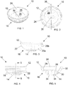
FIG. 1 is a perspective view of a plasma electrode in accordance with a first nonlimiting embodiment of the present invention. -
FIG. 2 is a top view showing a base of the electrode ofFIG. 1, and FIGS. 3 and 4 are side views of a functional surface of the electrode evidencing a plurality of substantially concentric planar steps or tiers that define the functional surface. -
FIG. 5 represents a cross-sectional view along line 5-5 ofFIG. 4 . -
FIG. 6 is a top view of a plasma electrode in accordance with a second nonlimiting embodiment of the present invention. -
FIG. 7 is a bottom view showing a functional surface of the electrode ofFIG. 6 . -
FIGS. 8 and 9 are side views of the electrode ofFIGS. 6 and 7 , whereinFIG. 8 is a side view ofFIG. 6 and FIG. 9 is a side view ofFIG. 7 . -
FIG. 10 is a perspective view representing the plasma electrode ofFIGS. 1 through 5 mounted to an electrosurgical device (instrument or probe) in accordance with a nonlimiting embodiment of the present invention. -
FIGS. 1 through 9 representvaporization electrodes electrode wide base apex surface functional surface functional surfaces electrodes - The
electrode 10 ofFIGS. 1 through 5 features a multi-stepped or multi-tieredfunctional surface 16 adapted to concentrate current overedges 22 defined by and between contiguous planar andarcuate surfaces tiers 18. Theelectrode 40 ofFIGS. 6 through 9 features a multi-faceted, semisphericalfunctional surface 46 adapted to concentrate current overedges 42 defined by and between contiguous planar surfaces orfacets 50 arranged intiers 48. Thevaporization electrodes electrodes FIGS. 1 through 9 , thefunctional surfaces electrode - As evident from
FIGS. 1 through 5 , thebase 12 of theelectrode 10 is opposite thefunctional surface 16 and itsapex surface 14, which is smaller in area than thebase 12. In the represented embodiment, theapex surface 14 is parallel to thebase 12 and perpendicular to theaxis 38 of theelectrode 10, though other configurations and orientations are possible, for example, thefunctional surface 16 could have one or more apices in the form of points or edges instead of a planar surface. Thebase 12 has a generally circular-shaped perimeter and is adapted for attachment to a feed conductor (80 inFIG. 10 ) for providing energy to theelectrode 10. The surface of thebase 12 is preferably electrically conductive, in other words, is not insulated with an electrically nonconductive coating or intermediate member. Methods of feed conductor connection and insulation in vaporization electrodes are well known to those of ordinary skill in the art, and all such methods are within the scope of the present invention. - Though bases with surfaces that are entirely planar are also within the scope of the invention, the
base 12 shown inFIGS. 1 through 5 has a recess orcavity 24 defined therein. A beneficial aspect of the presence of thecavity 24 is to reduce the mass of theelectrode 10, which is believed to promote faster plasma ignition. Thecavity 24 defines afloor 26 recessed below thebase 12, and a sloping annular-shaped surface 28 that surrounds and intersects thefloor 26, and in turn theannular surface 28 is surrounded and intersected by thebase 12. Abase wall 30 is defined by and between thefloor 26 of thecavity 24 and thefunctional surface 16, and aside wall 32 is defined by and between the annular-shapedsurface 28 of thecavity 24 and thefunctional surface 16. Thebase wall 30 is represented inFIG. 5 as being thicker than theside wall 32. A pair of through-holes 34 are defined in thebase wall 30 to facilitate connection to a pair of wires of thefeed conductor 80. Theholes 34 are represented as disposed on opposite sides of a plane ofsymmetry 36 of theelectrode 10, and define openings in theapex surface 14. In preferred embodiments of the invention, the distal ends of thefeed conductor 80 are typically flush or nearly flush with theapex surface 14 of theelectrode 10, as evident fromFIG. 10 , so as not to protrude from theapex surface 14. - The
multiple tiers 18, including atier 18 that defines theapex surface 14 that forms the axially outmost extent of theelectrode 10, define the three-dimensional shape of thefunctional surface 16. Thetiers 18 are sized and shaped so as to contribute an axi-symmetrical shape to thefunctional surface 16, and converge at theapex surface 14 that will be disposed closest to the targeted tissue during use of theelectrode 10. Thetiers 18 are represented as having circular perimeters and concentric with each other about theaxis 38 of theelectrode 10. Eachtier 18 is represented as having aplanar surface 20a facing in an axial direction of theelectrode 10 away from thebase 12, and cylindrical-shapedsurfaces 20b facing radially outward from theaxis 38 of theelectrode 10 so that eachsurface 20b surrounds and intersects one of theplanar surfaces 20a to define therebetween one of theedges 22 of thefunctional surface 16. Thesurfaces 20a are roughly perpendicular to theaxis 38 of theelectrode 10 and thesurfaces 20b are roughly parallel to theaxis 38 of theelectrode 10, such that theedges 22 generally define an included angle of about ninety degrees, though lesser and greater angles are also within the scope of the invention. As a result, theplanar surface 20a of onetier 18 is roughly perpendicular to thecylindrical surface 20b of anadjacent tier 18, such that a sharp interior corner is defined betweenadjacent tiers 18 having an included angle of about ninety degrees. However, it is also within the scope of the invention that at least one of the sharp interior corners could be replaced by an interior filet, for example, such that thesurfaces adjacent tiers 18 are arcuate portions of the filet, yet thesurfaces same tier 18 form anedge 22. - As evident from
FIGS. 3 through 5 , the axial dimensions of all but the first tier 18 (the axial dimensions of thesurfaces 20b) may be substantially equal, with a typical but nonlimiting example being about 0.005 inch (about 0.13 mm). However, the diameters of thetiers 18 preferably decrease in a nonlinear manner toward theapex surface 14 of thefunctional surface 16, with the result that the radial dimensions of the tiers 18 (the radial dimensions of thesurfaces 20a) gradually increase in a nonlinear manner with increasing distance from the base 12 (i.e., toward the apex surface 14). As nonlimiting examples, the radial dimensions of thesurfaces 20a may nonlinearly increase from about 0.002 (about 0.05 mm) adjacent the base 12 to about 0.009 (about 0.23 mm) adjacent theapex surface 14. The resulting shape of thefunctional surface 16 can be seen inFIGS. 3, 4 and 5 as somewhat semispherical in outline, but not smooth due to the presence of theedges 22. Other suitable but nonlimiting dimensions for theelectrode 10 include a diameter of about 0.125 inch (about 3.2 mm) at thebase 12, a diameter of about 0.050 inch (about 1.3 mm) at theapex surface 14, and an axial length of about 0.050 inch (about 1.3 mm). - The circular shapes of the
edges 22 and the juxtapositions of theedges 22 relative to each other (including the increasing radial distances between theedges 22 closer to the apex surface 14) are believed to provide certain advantages associated with the semispherical outline of thefunctional surface 16. In particular, current is believed to be concentrated along theedges 22 yet distributed over thefunctional surface 16, so that the surrounding plasma ignites in such a manner that provides concentrated and well-defined tissue removal. While the embodiment is shown inFIGS. 1 through 5 as having nine tiers 18 (including thetier 18 that forms the apex surface 14), fewer ormore tiers 18 may be utilized. While not wishing to be held to any particular theory, increasing numbers oftiers 18 are believed to promote plasma ignition (as a result of theedges 22 defining additional paths back to an associated return electrode/pole) and provide a better tissue removal effect (as a result of increasing current density). As an example, it is believed that theelectrode 10 preferably comprises at least fourtiers 18 between the base 12 andapex surface 14. - As evident from
FIGS. 6 through 9 , theelectrode 40 shares similarities with theelectrode 10 ofFIGS. 1 through 5 . For example, thebase 42 of theelectrode 40 is opposite itsfunctional surface 46 and itsapex surface 44, which is smaller in area than the base 42 and, in the represented embodiment, parallel to thebase 42. In addition, thebase 42 has a generally circular-shaped perimeter, is adapted for attachment to a feed conductor (80 inFIG. 10 ), and has a recess or cavity 54 defined therein. The cavity 54 defines afloor 56 recessed below thebase 42, and a slopingannular surface 58 that surrounds and intersects thefloor 56, and in turn theannular surface 58 is surrounded and intersected by thebase 42. Abase wall 60 is defined by and between thefloor 56 of the cavity 54 and thefunctional surface 46, and aside wall 62 is defined by and between theannular surface 58 of the cavity 54 and thefunctional surface 46. Thebase wall 60 is represented inFIGS. 8 and 9 as being thicker than theside wall 62. A pair of through-holes 64 are defined in thebase wall 60 to facilitate connection to a pair of wires of thefeed conductor 80. Theholes 64 are represented as disposed on opposite sides of a plane of symmetry 66 of theelectrode 40, and define openings in theapex surface 44. - The
functional surface 46 of theelectrode 40 is defined by themultiple facets 50 that contribute a non-smooth and generally semispherical shape to thesurface 46, somewhat resembling a cut gem. Thefacets 50 are shown as foursided and arranged to define threeconcentric tiers 48, each containing eightfacets 50. Thetiers 48 are represented as concentric with each other about theaxis 68 of theelectrode 40. Each adjacent pair offacets 50 meets to define anedge 52, each represented inFIGS. 6 through 9 as being entirely linear.Facets 50 located in thetier 48 closest to the base 42 are represented inFIGS. 8 and 9 as intersecting a cylindrical-shapedouter wall 70 that surrounds thebase 42, defining therewith arcuate edges 72. Thefacets 50 are sized and shaped so that thetiers 48 converge toward theapex surface 44, which will be disposed closest to the targeted tissue during use of theelectrode 40. Current is concentrated along thefacets 50 of thefunctional surface 46, and particularly along theedges 52 defined bycontiguous facets 50, thereby promoting concentrated and well-defined tissue removal. While the embodiment is shown inFIGS. 6 through 9 as having twenty-five facets 50 (twenty-four of which are arranged to define the three concentric tiers 48), eight radial subsections, fortylinear edges 52, and eightarcuate edges 72, theelectrode 40 could comprise fewer ormore facets 50, arranged in fewer ormore tiers 48. However, as previously noted for theelectrode 10 ofFIGS. 1 through 6 , the number oftiers 48 is believed to affect plasma ignition and tissue removal, and it is believed that theelectrode 40 preferably comprises at least threetiers 48 between the base 42 andapex surface 44. - Other aspects or potential variations for the
electrode 40 not discussed in any detail above can be, in terms of structure, function, materials, etc., essentially as was described for theelectrode 10. - In use, the
vaporization electrodes FIG. 10 shows theelectrode 10 ofFIGS. 1 through 6 mounted to feedconductors 80 of an electrosurgical device. Plasma builds up from current flow through an electrically conductive solution (e.g., saline) between theelectrode 10 and a return electrode/pole (not shown), and particularly over and around thefunctional surface 16 of theelectrode 10, such that tissue adjacent theelectrode 10 is heated by the plasma and vaporized without being directly contacted by theelectrode 10. The non-smooth, three-dimensional shapes of thefunctional surfaces electrodes surfaces - In investigations leading to the present invention, the
edges electrodes functional surfaces functional surfaces electrodes electrode 10/40 and tissue by "igniting" the saline solution between theelectrode 10/40 and tissue. In effect, theelectrodes electrodes functional surfaces edges functional surfaces - Though the invention has been described in reference to particular embodiments, these embodiments are nonlimiting examples of non-smooth, semispherical shapes within the scope of in this invention. Other possible embodiments are possible that contain the same or functionally similar non-smooth semispherical geometries comprising multiple edges and planar surfaces, and which are capable of providing the same or functionally similar advantages in tissue removal, efficiency, and usability. In addition, the dimensions of the planar surfaces of the
electrodes
Claims (11)
- A vaporization electrode (10,40) configured for attachment to a feed conductor (80) of an electrosurgical device, the electrode (10,40) comprising:an axis (38,68);a non-smooth semispherical shape defined by a functional surface (16,46) converging toward an apex surface (14,44) of the functional surface (16,46) on the axis (38,68), the functional surface (16,46) having a plurality of individual surfaces (20a,20b,50) that intersect each other to define edges (22,52) therebetween; anda base (12,42) oppositely disposed from the functional surface (16,46) and the apex surface (14,44) thereof, parallel to the apex surface (14,44), and perpendicular to the axis (38,68);wherein the plurality of individual surfaces (20a,20b,50) comprise:planar surfaces (20a) that are perpendicular to the axis (38) and face away from the base (12) and cylindrical surfaces (20b) that are parallel to the axis (38) and face radially outward from the axis (38), the planar surfaces (20a) and the cylindrical surfaces (20b) being arranged in concentric annular-shaped tiers (18) so that each cylindrical surface (20b) surrounds and intersects one of the planar surfaces (20a) to define therebetween one of the edges (22) of the functional surface (16); ormultiple planar facets (50) that are arranged to define multiple concentric tiers (48), adjacent pairs of the facets (50) intersecting to define the edges (52) of the functional surface (16), the edges (52) being entirely linear and being sized and shaped so that the tiers (48) converge toward the apex surface (44);the electrode (10,40) being configured to attach the feed conductor (80) at the base (12,42) to provide energy to the functional surface (16,46) and distribute the energy from the functional surface (16,46) over a semispherical area.
- The vaporization electrode (10,40) according to claim 1, wherein the apex surface (14,44) is a planar surface and parallel to the base (12,42).
- The vaporization electrode (10,40) according to claim 1 or 2, wherein the individual surfaces (20a,20b,50) of the functional surface (16,46) comprise the planar surfaces (20a) and the cylindrical surfaces (20b).
- The vaporization electrode (10) according to claim 3, wherein the tiers (18) are concentric with the apex surface (14).
- The vaporization electrode (10) according to claim 3 or 4, wherein the planar surfaces (20a) of the functional surface (16) comprise at least four of the concentric annular-shaped tiers (18).
- The vaporization electrode (40) according to claim 1 or 2, wherein the individual surfaces (50) of the functional surface (46) comprise the multiple planar facets (50) that intersect to define the edges (52) therebetween.
- The vaporization electrode (40) according to claim 6, wherein the multiple planar facets (50) are arranged on the functional surface (46) to define concentric annular-shaped tiers (48), and the edges (52) are defined by and between the multiple planar facets (50) within each of the tiers (48) and by and between the multiple planar facets (50) of adjacent pairs of the tiers (48).
- The vaporization electrode (40) according to claim 6 or 7, wherein the tiers (48) are concentric with the apex surface (44).
- The vaporization electrode (10,40) according to any one of claims 1 to 8, wherein the base (12,42) has a circular periphery.
- The vaporization electrode (10,40) according to any one of claims 1 to 9, wherein the base (12,42) has a recess (24,54) defined therein that defines a base wall (30,60) of the electrode (10,40), and the base wall (30,60) has through-holes (34,64) therein for connecting to the feed conductor (80).
- An electrosurgical device comprising:at least one feed conductor (80); anda vaporization electrode (10,40) according to any one of claims 1 to 10, the vaporization electrode (10,40) being mounted to the feed conductor (80), the feed conductor (80) being attached to the base (12,42) to provide energy to the electrode (10) and distribute the energy from the functional surface (16,46) over a semispherical area.
Applications Claiming Priority (2)
| Application Number | Priority Date | Filing Date | Title |
|---|---|---|---|
| US201461971050P | 2014-03-27 | 2014-03-27 | |
| PCT/US2015/023037 WO2015148949A1 (en) | 2014-03-27 | 2015-03-27 | Vaporization electrodes and electrosurgical devices equipped therewith |
Publications (3)
| Publication Number | Publication Date |
|---|---|
| EP3122273A1 EP3122273A1 (en) | 2017-02-01 |
| EP3122273A4 EP3122273A4 (en) | 2017-12-06 |
| EP3122273B1 true EP3122273B1 (en) | 2019-11-27 |
Family
ID=54196450
Family Applications (1)
| Application Number | Title | Priority Date | Filing Date |
|---|---|---|---|
| EP15768023.2A Active EP3122273B1 (en) | 2014-03-27 | 2015-03-27 | Vaporization electrodes and electrosurgical devices equipped therewith |
Country Status (3)
| Country | Link |
|---|---|
| US (1) | US11147612B2 (en) |
| EP (1) | EP3122273B1 (en) |
| WO (1) | WO2015148949A1 (en) |
Family Cites Families (17)
| Publication number | Priority date | Publication date | Assignee | Title |
|---|---|---|---|---|
| US5354296A (en) * | 1993-03-24 | 1994-10-11 | Symbiosis Corporation | Electrocautery probe with variable morphology electrode |
| US5395363A (en) * | 1993-06-29 | 1995-03-07 | Utah Medical Products | Diathermy coagulation and ablation apparatus and method |
| US6197025B1 (en) * | 1994-09-30 | 2001-03-06 | Circon Corporation | Grooved slider electrode for a resectoscope |
| US5669906A (en) * | 1994-09-30 | 1997-09-23 | Circon Corporation | Grooved roller electrode for a resectoscope |
| US6032673A (en) * | 1994-10-13 | 2000-03-07 | Femrx, Inc. | Methods and devices for tissue removal |
| US5779700A (en) * | 1995-04-20 | 1998-07-14 | Symbiosis Corporation | Roller electrodes for electrocautery probes for use with a resectroscope |
| US5827274A (en) * | 1995-07-18 | 1998-10-27 | Richard Wolf Gmbh | Electrode for vaporizing tissue |
| GB9521772D0 (en) * | 1995-10-24 | 1996-01-03 | Gyrus Medical Ltd | An electrosurgical instrument |
| US5759183A (en) * | 1996-11-05 | 1998-06-02 | Vandusseldorp; Gregg A. | Vaporizing roller for an electrosurgical probe |
| GB9807303D0 (en) * | 1998-04-03 | 1998-06-03 | Gyrus Medical Ltd | An electrode assembly for an electrosurgical instrument |
| WO2002054941A2 (en) * | 2001-01-11 | 2002-07-18 | Rita Medical Systems Inc | Bone-treatment instrument and method |
| US7704249B2 (en) * | 2004-05-07 | 2010-04-27 | Arthrocare Corporation | Apparatus and methods for electrosurgical ablation and resection of target tissue |
| US8177784B2 (en) * | 2006-09-27 | 2012-05-15 | Electromedical Associates, Llc | Electrosurgical device having floating potential electrode and adapted for use with a resectoscope |
| US9283029B2 (en) * | 2007-01-31 | 2016-03-15 | Alma Lasers Ltd. | Skin treatment using a multi-discharge applicator |
| ATE553714T1 (en) * | 2008-12-16 | 2012-05-15 | Arthrex Inc | ELECTROSURGICAL ABLATION DEVICE HAVING A TUBULAR ELECTRODE WITH ARCH-SHAPED FELLOWS |
| US9168084B2 (en) * | 2010-05-11 | 2015-10-27 | Electromedical Associates, Llc | Brazed electrosurgical device |
| US8682410B2 (en) * | 2011-03-10 | 2014-03-25 | Medtronic Ablation Frontiers Llc | Multi-array monophasic action potential medical device |
-
2015
- 2015-03-27 WO PCT/US2015/023037 patent/WO2015148949A1/en active Application Filing
- 2015-03-27 EP EP15768023.2A patent/EP3122273B1/en active Active
-
2019
- 2019-05-07 US US16/405,504 patent/US11147612B2/en active Active
Non-Patent Citations (1)
| Title |
|---|
| None * |
Also Published As
| Publication number | Publication date |
|---|---|
| US20190269453A1 (en) | 2019-09-05 |
| WO2015148949A1 (en) | 2015-10-01 |
| EP3122273A4 (en) | 2017-12-06 |
| US11147612B2 (en) | 2021-10-19 |
| EP3122273A1 (en) | 2017-02-01 |
Similar Documents
| Publication | Publication Date | Title |
|---|---|---|
| AU750115B2 (en) | Cellular sublimation probe and methods | |
| US9271784B2 (en) | Fine dissection electrosurgical device | |
| US8348944B2 (en) | Electrosurgical device having floating-potential electrode and bubble trap | |
| US7563261B2 (en) | Electrosurgical device with floating-potential electrodes | |
| EP1853188B1 (en) | Device for thermal ablation of biological tissue using spherical ablation patterns | |
| EP2124792B1 (en) | Instruments for thermal tissue treatment | |
| EP2767250B1 (en) | Electrosurgical electrodes | |
| US20030130653A1 (en) | Electrosurgical tissue removal with a selectively insulated electrode | |
| US20120203219A1 (en) | Fine dissection electrosurgical device | |
| US9888954B2 (en) | Plasma resection electrode | |
| US8986299B2 (en) | Ablator with scalloped electrode and swaged tube | |
| WO1998019612A1 (en) | Vaporizing roller for an electrosurgical probe | |
| US10278767B2 (en) | Vaporization electrodes and electrosurgical devices equipped therewith | |
| US11147612B2 (en) | Vaporization electrodes and electrosurgical devices equipped therewith | |
| EP1874209A1 (en) | Apparatus and method for making a spherical lesion | |
| GB2514231A (en) | Fine dissection electrosurgical device | |
| EP2877112A1 (en) | A high-frequency electromagnetic energy active ablation device |
Legal Events
| Date | Code | Title | Description |
|---|---|---|---|
| STAA | Information on the status of an ep patent application or granted ep patent |
Free format text: STATUS: THE INTERNATIONAL PUBLICATION HAS BEEN MADE |
|
| PUAI | Public reference made under article 153(3) epc to a published international application that has entered the european phase |
Free format text: ORIGINAL CODE: 0009012 |
|
| STAA | Information on the status of an ep patent application or granted ep patent |
Free format text: STATUS: REQUEST FOR EXAMINATION WAS MADE |
|
| 17P | Request for examination filed |
Effective date: 20160908 |
|
| AK | Designated contracting states |
Kind code of ref document: A1 Designated state(s): AL AT BE BG CH CY CZ DE DK EE ES FI FR GB GR HR HU IE IS IT LI LT LU LV MC MK MT NL NO PL PT RO RS SE SI SK SM TR |
|
| AX | Request for extension of the european patent |
Extension state: BA ME |
|
| DAV | Request for validation of the european patent (deleted) | ||
| DAX | Request for extension of the european patent (deleted) | ||
| A4 | Supplementary search report drawn up and despatched |
Effective date: 20171107 |
|
| RIC1 | Information provided on ipc code assigned before grant |
Ipc: A61B 18/12 20060101AFI20171030BHEP Ipc: A61B 18/14 20060101ALI20171030BHEP Ipc: A61B 18/00 20060101ALI20171030BHEP |
|
| STAA | Information on the status of an ep patent application or granted ep patent |
Free format text: STATUS: EXAMINATION IS IN PROGRESS |
|
| 17Q | First examination report despatched |
Effective date: 20180626 |
|
| GRAP | Despatch of communication of intention to grant a patent |
Free format text: ORIGINAL CODE: EPIDOSNIGR1 |
|
| STAA | Information on the status of an ep patent application or granted ep patent |
Free format text: STATUS: GRANT OF PATENT IS INTENDED |
|
| INTG | Intention to grant announced |
Effective date: 20190607 |
|
| GRAS | Grant fee paid |
Free format text: ORIGINAL CODE: EPIDOSNIGR3 |
|
| GRAA | (expected) grant |
Free format text: ORIGINAL CODE: 0009210 |
|
| STAA | Information on the status of an ep patent application or granted ep patent |
Free format text: STATUS: THE PATENT HAS BEEN GRANTED |
|
| AK | Designated contracting states |
Kind code of ref document: B1 Designated state(s): AL AT BE BG CH CY CZ DE DK EE ES FI FR GB GR HR HU IE IS IT LI LT LU LV MC MK MT NL NO PL PT RO RS SE SI SK SM TR |
|
| REG | Reference to a national code |
Ref country code: GB Ref legal event code: FG4D |
|
| REG | Reference to a national code |
Ref country code: CH Ref legal event code: EP |
|
| REG | Reference to a national code |
Ref country code: AT Ref legal event code: REF Ref document number: 1205858 Country of ref document: AT Kind code of ref document: T Effective date: 20191215 |
|
| REG | Reference to a national code |
Ref country code: DE Ref legal event code: R096 Ref document number: 602015042558 Country of ref document: DE |
|
| REG | Reference to a national code |
Ref country code: IE Ref legal event code: FG4D |
|
| REG | Reference to a national code |
Ref country code: NL Ref legal event code: MP Effective date: 20191127 |
|
| REG | Reference to a national code |
Ref country code: LT Ref legal event code: MG4D |
|
| PG25 | Lapsed in a contracting state [announced via postgrant information from national office to epo] |
Ref country code: BG Free format text: LAPSE BECAUSE OF FAILURE TO SUBMIT A TRANSLATION OF THE DESCRIPTION OR TO PAY THE FEE WITHIN THE PRESCRIBED TIME-LIMIT Effective date: 20200227 Ref country code: GR Free format text: LAPSE BECAUSE OF FAILURE TO SUBMIT A TRANSLATION OF THE DESCRIPTION OR TO PAY THE FEE WITHIN THE PRESCRIBED TIME-LIMIT Effective date: 20200228 Ref country code: FI Free format text: LAPSE BECAUSE OF FAILURE TO SUBMIT A TRANSLATION OF THE DESCRIPTION OR TO PAY THE FEE WITHIN THE PRESCRIBED TIME-LIMIT Effective date: 20191127 Ref country code: LT Free format text: LAPSE BECAUSE OF FAILURE TO SUBMIT A TRANSLATION OF THE DESCRIPTION OR TO PAY THE FEE WITHIN THE PRESCRIBED TIME-LIMIT Effective date: 20191127 Ref country code: NL Free format text: LAPSE BECAUSE OF FAILURE TO SUBMIT A TRANSLATION OF THE DESCRIPTION OR TO PAY THE FEE WITHIN THE PRESCRIBED TIME-LIMIT Effective date: 20191127 Ref country code: SE Free format text: LAPSE BECAUSE OF FAILURE TO SUBMIT A TRANSLATION OF THE DESCRIPTION OR TO PAY THE FEE WITHIN THE PRESCRIBED TIME-LIMIT Effective date: 20191127 Ref country code: LV Free format text: LAPSE BECAUSE OF FAILURE TO SUBMIT A TRANSLATION OF THE DESCRIPTION OR TO PAY THE FEE WITHIN THE PRESCRIBED TIME-LIMIT Effective date: 20191127 Ref country code: NO Free format text: LAPSE BECAUSE OF FAILURE TO SUBMIT A TRANSLATION OF THE DESCRIPTION OR TO PAY THE FEE WITHIN THE PRESCRIBED TIME-LIMIT Effective date: 20200227 |
|
| PG25 | Lapsed in a contracting state [announced via postgrant information from national office to epo] |
Ref country code: IS Free format text: LAPSE BECAUSE OF FAILURE TO SUBMIT A TRANSLATION OF THE DESCRIPTION OR TO PAY THE FEE WITHIN THE PRESCRIBED TIME-LIMIT Effective date: 20200327 Ref country code: RS Free format text: LAPSE BECAUSE OF FAILURE TO SUBMIT A TRANSLATION OF THE DESCRIPTION OR TO PAY THE FEE WITHIN THE PRESCRIBED TIME-LIMIT Effective date: 20191127 Ref country code: HR Free format text: LAPSE BECAUSE OF FAILURE TO SUBMIT A TRANSLATION OF THE DESCRIPTION OR TO PAY THE FEE WITHIN THE PRESCRIBED TIME-LIMIT Effective date: 20191127 |
|
| PG25 | Lapsed in a contracting state [announced via postgrant information from national office to epo] |
Ref country code: AL Free format text: LAPSE BECAUSE OF FAILURE TO SUBMIT A TRANSLATION OF THE DESCRIPTION OR TO PAY THE FEE WITHIN THE PRESCRIBED TIME-LIMIT Effective date: 20191127 |
|
| PG25 | Lapsed in a contracting state [announced via postgrant information from national office to epo] |
Ref country code: ES Free format text: LAPSE BECAUSE OF FAILURE TO SUBMIT A TRANSLATION OF THE DESCRIPTION OR TO PAY THE FEE WITHIN THE PRESCRIBED TIME-LIMIT Effective date: 20191127 Ref country code: CZ Free format text: LAPSE BECAUSE OF FAILURE TO SUBMIT A TRANSLATION OF THE DESCRIPTION OR TO PAY THE FEE WITHIN THE PRESCRIBED TIME-LIMIT Effective date: 20191127 Ref country code: RO Free format text: LAPSE BECAUSE OF FAILURE TO SUBMIT A TRANSLATION OF THE DESCRIPTION OR TO PAY THE FEE WITHIN THE PRESCRIBED TIME-LIMIT Effective date: 20191127 Ref country code: EE Free format text: LAPSE BECAUSE OF FAILURE TO SUBMIT A TRANSLATION OF THE DESCRIPTION OR TO PAY THE FEE WITHIN THE PRESCRIBED TIME-LIMIT Effective date: 20191127 Ref country code: PT Free format text: LAPSE BECAUSE OF FAILURE TO SUBMIT A TRANSLATION OF THE DESCRIPTION OR TO PAY THE FEE WITHIN THE PRESCRIBED TIME-LIMIT Effective date: 20200419 Ref country code: DK Free format text: LAPSE BECAUSE OF FAILURE TO SUBMIT A TRANSLATION OF THE DESCRIPTION OR TO PAY THE FEE WITHIN THE PRESCRIBED TIME-LIMIT Effective date: 20191127 |
|
| REG | Reference to a national code |
Ref country code: DE Ref legal event code: R097 Ref document number: 602015042558 Country of ref document: DE |
|
| PG25 | Lapsed in a contracting state [announced via postgrant information from national office to epo] |
Ref country code: SK Free format text: LAPSE BECAUSE OF FAILURE TO SUBMIT A TRANSLATION OF THE DESCRIPTION OR TO PAY THE FEE WITHIN THE PRESCRIBED TIME-LIMIT Effective date: 20191127 Ref country code: SM Free format text: LAPSE BECAUSE OF FAILURE TO SUBMIT A TRANSLATION OF THE DESCRIPTION OR TO PAY THE FEE WITHIN THE PRESCRIBED TIME-LIMIT Effective date: 20191127 |
|
| REG | Reference to a national code |
Ref country code: AT Ref legal event code: MK05 Ref document number: 1205858 Country of ref document: AT Kind code of ref document: T Effective date: 20191127 |
|
| REG | Reference to a national code |
Ref country code: DE Ref legal event code: R119 Ref document number: 602015042558 Country of ref document: DE |
|
| PLBE | No opposition filed within time limit |
Free format text: ORIGINAL CODE: 0009261 |
|
| STAA | Information on the status of an ep patent application or granted ep patent |
Free format text: STATUS: NO OPPOSITION FILED WITHIN TIME LIMIT |
|
| PG25 | Lapsed in a contracting state [announced via postgrant information from national office to epo] |
Ref country code: MC Free format text: LAPSE BECAUSE OF FAILURE TO SUBMIT A TRANSLATION OF THE DESCRIPTION OR TO PAY THE FEE WITHIN THE PRESCRIBED TIME-LIMIT Effective date: 20191127 |
|
| REG | Reference to a national code |
Ref country code: CH Ref legal event code: PL |
|
| 26N | No opposition filed |
Effective date: 20200828 |
|
| PG25 | Lapsed in a contracting state [announced via postgrant information from national office to epo] |
Ref country code: PL Free format text: LAPSE BECAUSE OF FAILURE TO SUBMIT A TRANSLATION OF THE DESCRIPTION OR TO PAY THE FEE WITHIN THE PRESCRIBED TIME-LIMIT Effective date: 20191127 Ref country code: AT Free format text: LAPSE BECAUSE OF FAILURE TO SUBMIT A TRANSLATION OF THE DESCRIPTION OR TO PAY THE FEE WITHIN THE PRESCRIBED TIME-LIMIT Effective date: 20191127 Ref country code: SI Free format text: LAPSE BECAUSE OF FAILURE TO SUBMIT A TRANSLATION OF THE DESCRIPTION OR TO PAY THE FEE WITHIN THE PRESCRIBED TIME-LIMIT Effective date: 20191127 |
|
| REG | Reference to a national code |
Ref country code: BE Ref legal event code: MM Effective date: 20200331 |
|
| PG25 | Lapsed in a contracting state [announced via postgrant information from national office to epo] |
Ref country code: LU Free format text: LAPSE BECAUSE OF NON-PAYMENT OF DUE FEES Effective date: 20200327 |
|
| PG25 | Lapsed in a contracting state [announced via postgrant information from national office to epo] |
Ref country code: FR Free format text: LAPSE BECAUSE OF NON-PAYMENT OF DUE FEES Effective date: 20200331 Ref country code: CH Free format text: LAPSE BECAUSE OF NON-PAYMENT OF DUE FEES Effective date: 20200331 Ref country code: IE Free format text: LAPSE BECAUSE OF NON-PAYMENT OF DUE FEES Effective date: 20200327 Ref country code: DE Free format text: LAPSE BECAUSE OF NON-PAYMENT OF DUE FEES Effective date: 20201001 Ref country code: LI Free format text: LAPSE BECAUSE OF NON-PAYMENT OF DUE FEES Effective date: 20200331 Ref country code: IT Free format text: LAPSE BECAUSE OF FAILURE TO SUBMIT A TRANSLATION OF THE DESCRIPTION OR TO PAY THE FEE WITHIN THE PRESCRIBED TIME-LIMIT Effective date: 20191127 |
|
| PG25 | Lapsed in a contracting state [announced via postgrant information from national office to epo] |
Ref country code: BE Free format text: LAPSE BECAUSE OF NON-PAYMENT OF DUE FEES Effective date: 20200331 |
|
| GBPC | Gb: european patent ceased through non-payment of renewal fee |
Effective date: 20200327 |
|
| PG25 | Lapsed in a contracting state [announced via postgrant information from national office to epo] |
Ref country code: GB Free format text: LAPSE BECAUSE OF NON-PAYMENT OF DUE FEES Effective date: 20200327 |
|
| PG25 | Lapsed in a contracting state [announced via postgrant information from national office to epo] |
Ref country code: TR Free format text: LAPSE BECAUSE OF FAILURE TO SUBMIT A TRANSLATION OF THE DESCRIPTION OR TO PAY THE FEE WITHIN THE PRESCRIBED TIME-LIMIT Effective date: 20191127 Ref country code: MT Free format text: LAPSE BECAUSE OF FAILURE TO SUBMIT A TRANSLATION OF THE DESCRIPTION OR TO PAY THE FEE WITHIN THE PRESCRIBED TIME-LIMIT Effective date: 20191127 Ref country code: CY Free format text: LAPSE BECAUSE OF FAILURE TO SUBMIT A TRANSLATION OF THE DESCRIPTION OR TO PAY THE FEE WITHIN THE PRESCRIBED TIME-LIMIT Effective date: 20191127 |
|
| PG25 | Lapsed in a contracting state [announced via postgrant information from national office to epo] |
Ref country code: MK Free format text: LAPSE BECAUSE OF FAILURE TO SUBMIT A TRANSLATION OF THE DESCRIPTION OR TO PAY THE FEE WITHIN THE PRESCRIBED TIME-LIMIT Effective date: 20191127 |