EP3119342B1 - System for maintaining a tool pose - Google Patents
System for maintaining a tool pose Download PDFInfo
- Publication number
- EP3119342B1 EP3119342B1 EP15765922.8A EP15765922A EP3119342B1 EP 3119342 B1 EP3119342 B1 EP 3119342B1 EP 15765922 A EP15765922 A EP 15765922A EP 3119342 B1 EP3119342 B1 EP 3119342B1
- Authority
- EP
- European Patent Office
- Prior art keywords
- joints
- tool
- coordinate frame
- transform
- movement
- Prior art date
- Legal status (The legal status is an assumption and is not a legal conclusion. Google has not performed a legal analysis and makes no representation as to the accuracy of the status listed.)
- Active
Links
- 230000033001 locomotion Effects 0.000 claims description 113
- 238000000034 method Methods 0.000 claims description 56
- 210000001503 joint Anatomy 0.000 description 161
- 239000012636 effector Substances 0.000 description 24
- 230000008569 process Effects 0.000 description 20
- 230000008859 change Effects 0.000 description 8
- 238000010586 diagram Methods 0.000 description 8
- 238000003384 imaging method Methods 0.000 description 7
- 238000003780 insertion Methods 0.000 description 7
- 230000037431 insertion Effects 0.000 description 7
- 230000006378 damage Effects 0.000 description 6
- 210000000323 shoulder joint Anatomy 0.000 description 6
- 230000002441 reversible effect Effects 0.000 description 5
- 210000003857 wrist joint Anatomy 0.000 description 5
- 208000027418 Wounds and injury Diseases 0.000 description 4
- 208000014674 injury Diseases 0.000 description 4
- 230000000694 effects Effects 0.000 description 3
- 239000011159 matrix material Substances 0.000 description 3
- 230000003068 static effect Effects 0.000 description 3
- 230000004075 alteration Effects 0.000 description 2
- 238000003491 array Methods 0.000 description 2
- 239000002131 composite material Substances 0.000 description 2
- 230000001419 dependent effect Effects 0.000 description 2
- 238000001514 detection method Methods 0.000 description 2
- 230000000977 initiatory effect Effects 0.000 description 2
- 238000012986 modification Methods 0.000 description 2
- 230000004048 modification Effects 0.000 description 2
- 230000003287 optical effect Effects 0.000 description 2
- 230000002028 premature Effects 0.000 description 2
- 238000012545 processing Methods 0.000 description 2
- 238000001356 surgical procedure Methods 0.000 description 2
- 238000010408 sweeping Methods 0.000 description 2
- 230000001052 transient effect Effects 0.000 description 2
- 238000013519 translation Methods 0.000 description 2
- 206010061258 Joint lock Diseases 0.000 description 1
- 239000000853 adhesive Substances 0.000 description 1
- 230000001070 adhesive effect Effects 0.000 description 1
- 210000003484 anatomy Anatomy 0.000 description 1
- 230000004397 blinking Effects 0.000 description 1
- 238000012937 correction Methods 0.000 description 1
- 238000013461 design Methods 0.000 description 1
- 238000001914 filtration Methods 0.000 description 1
- 230000006870 function Effects 0.000 description 1
- 239000011521 glass Substances 0.000 description 1
- 238000001990 intravenous administration Methods 0.000 description 1
- 230000000670 limiting effect Effects 0.000 description 1
- 238000013507 mapping Methods 0.000 description 1
- QSHDDOUJBYECFT-UHFFFAOYSA-N mercury Chemical compound [Hg] QSHDDOUJBYECFT-UHFFFAOYSA-N 0.000 description 1
- 229910052753 mercury Inorganic materials 0.000 description 1
- 239000000203 mixture Substances 0.000 description 1
- 210000000056 organ Anatomy 0.000 description 1
- 230000036961 partial effect Effects 0.000 description 1
- 230000002829 reductive effect Effects 0.000 description 1
- 239000000565 sealant Substances 0.000 description 1
- 239000000725 suspension Substances 0.000 description 1
- 230000009466 transformation Effects 0.000 description 1
- 238000000844 transformation Methods 0.000 description 1
- 230000001131 transforming effect Effects 0.000 description 1
- 230000000007 visual effect Effects 0.000 description 1
Images


Classifications
-
- A—HUMAN NECESSITIES
- A61—MEDICAL OR VETERINARY SCIENCE; HYGIENE
- A61B—DIAGNOSIS; SURGERY; IDENTIFICATION
- A61B34/00—Computer-aided surgery; Manipulators or robots specially adapted for use in surgery
- A61B34/70—Manipulators specially adapted for use in surgery
-
- A—HUMAN NECESSITIES
- A61—MEDICAL OR VETERINARY SCIENCE; HYGIENE
- A61B—DIAGNOSIS; SURGERY; IDENTIFICATION
- A61B34/00—Computer-aided surgery; Manipulators or robots specially adapted for use in surgery
- A61B34/30—Surgical robots
-
- A—HUMAN NECESSITIES
- A61—MEDICAL OR VETERINARY SCIENCE; HYGIENE
- A61B—DIAGNOSIS; SURGERY; IDENTIFICATION
- A61B1/00—Instruments for performing medical examinations of the interior of cavities or tubes of the body by visual or photographical inspection, e.g. endoscopes; Illuminating arrangements therefor
- A61B1/00147—Holding or positioning arrangements
- A61B1/00149—Holding or positioning arrangements using articulated arms
-
- A—HUMAN NECESSITIES
- A61—MEDICAL OR VETERINARY SCIENCE; HYGIENE
- A61B—DIAGNOSIS; SURGERY; IDENTIFICATION
- A61B34/00—Computer-aided surgery; Manipulators or robots specially adapted for use in surgery
- A61B34/30—Surgical robots
- A61B34/35—Surgical robots for telesurgery
-
- B—PERFORMING OPERATIONS; TRANSPORTING
- B25—HAND TOOLS; PORTABLE POWER-DRIVEN TOOLS; MANIPULATORS
- B25J—MANIPULATORS; CHAMBERS PROVIDED WITH MANIPULATION DEVICES
- B25J9/00—Programme-controlled manipulators
- B25J9/16—Programme controls
- B25J9/1602—Programme controls characterised by the control system, structure, architecture
- B25J9/1607—Calculation of inertia, jacobian matrixes and inverses
-
- B—PERFORMING OPERATIONS; TRANSPORTING
- B25—HAND TOOLS; PORTABLE POWER-DRIVEN TOOLS; MANIPULATORS
- B25J—MANIPULATORS; CHAMBERS PROVIDED WITH MANIPULATION DEVICES
- B25J9/00—Programme-controlled manipulators
- B25J9/16—Programme controls
- B25J9/1628—Programme controls characterised by the control loop
- B25J9/1633—Programme controls characterised by the control loop compliant, force, torque control, e.g. combined with position control
-
- A—HUMAN NECESSITIES
- A61—MEDICAL OR VETERINARY SCIENCE; HYGIENE
- A61B—DIAGNOSIS; SURGERY; IDENTIFICATION
- A61B17/00—Surgical instruments, devices or methods, e.g. tourniquets
- A61B2017/00017—Electrical control of surgical instruments
-
- A—HUMAN NECESSITIES
- A61—MEDICAL OR VETERINARY SCIENCE; HYGIENE
- A61B—DIAGNOSIS; SURGERY; IDENTIFICATION
- A61B34/00—Computer-aided surgery; Manipulators or robots specially adapted for use in surgery
- A61B34/20—Surgical navigation systems; Devices for tracking or guiding surgical instruments, e.g. for frameless stereotaxis
- A61B2034/2046—Tracking techniques
- A61B2034/2059—Mechanical position encoders
-
- A—HUMAN NECESSITIES
- A61—MEDICAL OR VETERINARY SCIENCE; HYGIENE
- A61B—DIAGNOSIS; SURGERY; IDENTIFICATION
- A61B34/00—Computer-aided surgery; Manipulators or robots specially adapted for use in surgery
- A61B34/30—Surgical robots
- A61B2034/301—Surgical robots for introducing or steering flexible instruments inserted into the body, e.g. catheters or endoscopes
-
- A—HUMAN NECESSITIES
- A61—MEDICAL OR VETERINARY SCIENCE; HYGIENE
- A61B—DIAGNOSIS; SURGERY; IDENTIFICATION
- A61B34/00—Computer-aided surgery; Manipulators or robots specially adapted for use in surgery
- A61B34/30—Surgical robots
- A61B2034/304—Surgical robots including a freely orientable platform, e.g. so called 'Stewart platforms'
-
- A—HUMAN NECESSITIES
- A61—MEDICAL OR VETERINARY SCIENCE; HYGIENE
- A61B—DIAGNOSIS; SURGERY; IDENTIFICATION
- A61B34/00—Computer-aided surgery; Manipulators or robots specially adapted for use in surgery
- A61B34/30—Surgical robots
- A61B2034/305—Details of wrist mechanisms at distal ends of robotic arms
Definitions
- the present disclosure relates generally to operation of devices with articulated arms and more particularly to maintaining a tool pose.
- These electronic devices provide both advantages and challenges to the personnel operating them. Many of these electronic devices may be capable of autonomous or semiautonomous motion of one or more articulated arms and/or end effectors. These one or more articulated arms and/or end effectors each include a combination of links and articulated joints that support motion of the articulated arms and/or end effectors. In many cases, the articulated joints are manipulated to obtain a desired position and/or orientation (collectively, a desired pose) of a corresponding tool located at a distal end of the links and articulated joints of a corresponding articulated arm and/or end effector.
- Each of the articulated joints proximal to the tool provides the corresponding articulated arm and/or end effector with at least one degree of freedom that may be used to manipulate the position and/or orientation of the corresponding tool.
- the corresponding articulated arms and/or end effectors may include at least six degrees of freedom that allow for controlling a x, y, and z position of the corresponding tool as well as a roll, pitch, and yaw orientation of the corresponding tool.
- the corresponding articulated arms and/or end effectors are often designed to include redundant degrees of freedom.
- the articulated arm and/or end effector may be subject to motion, both planned and unplanned, that may result in movement in one or more of the articulated joints.
- this motion changes the positions and/or orientations of the one or more articulated joints, the changes may introduce undesirable alteration to the pose of a tool being manipulated by the articulated arm.
- This alteration to the pose may result in injury to a patient, injury to personnel in proximity to the articulated arms and/or end effectors, damage to the articulated arms and/or end effectors, damage to other devices in proximity to the articulated arms and/or end effectors, breach of a sterile field, and/or other undesirable outcomes.
- US 2011/0276059 A1 discloses telerobotic, telesurgical, and/or surgical robotic devices, systems, and methods which employ surgical robotic linkages that may have more degrees of freedom than an associated surgical end effector n space.
- a processor can calculate a tool motion that includes pivoting of the tool about an aperture site.
- Linkages movable along a range of configurations for a given end effector position may be driven toward configurations which inhibit collisions.
- EP 1 234 641 A1 discloses a robot controller for keeping the posture of a tool in a task coordinate system by a simple processing and allowing a robot to perform flexible translational motion.
- EP 1 642 690 A2 discloses a method for controlling the trajectory of a robot, in which, in the cooperative operation of a leading robot having a work tool and a tracking robot gripping a workpiece, the position and the orientation of the work tool may be desirably controlled, even when the interpolative motion is carried out.
- the robots are cooperatively controlled such that the position and the orientation of a first tool coordinate system set on the work tool attached to the leading robot is moved along a desired trajectory on a second tool coordinate system set on the workpiece gripped by the tracking robot.
- the interpolative position data of the tracking robot is calculated by using the interpolative position data of the leading robot and the relative positions and the relative orientations data of the robots.
- the invention may be applied to a manual feed.
- the trajectory may be smoothed by filtering the interpolative position data.
- US 5,465,037 A discloses a system and method for seam tracking in real time without path preprogramming uses at least two degrees of freedom and at least one degree of freedom created by a redundant axis.
- a robot can be used to weld or apply adhesive or sealant to a workpiece that is mounted on a positioner that it is movable relative to a base of the robot as a movable end of the robot tracks a seam on the workpiece.
- a sensor expresses a seam trajectory in workpiece coordinates and queues the coordinates in a computer processor so that the coordinates can be extracted from the processor to cause the movable end of the robot to track the seam.
- the workpiece can remain stationary and the robot base can be moved or the base can remain stationary and the workpiece can be moved or both the workpiece and the robot base can be moved.
- Any reasonable number of redundant axes can be utilized so long as there is one control parameter independently defined for each degree of freedom greater than six. Previous seam tracking systems do not have more than one degree of freedom with one of the degrees of freedom being created by redundant axes and previous systems do not automatically move the robot base relative to the workpiece
- DE102008041602A1 discloses a device for maintaining the orientation and position of a robotic tool using redundant joints.
- the present invention provides a computer-assisted medical device comprising: an articulated arm comprising one or more first joints and one or more second joints, the articulated arm configured to hold a tool distal to the one or more first joints and the one or more second joints; and a control unit coupled to the one or more first joints and the one or more second joints; wherein, during movement of the one or more first joints, the control unit maintains a position and an orientation of the tool using the one or more second joints by: determining a reference coordinate frame for the tool; determining a reference transform of the tool in the reference coordinate frame prior to the movement of the one or more first joints; determining an actual transform of the tool in the reference coordinate frame while the one or more first joints are being moved; determining differences between the reference transform and the actual transform; and maintaining the position and orientation of the tool by driving the one or more second joints based on the differences.
- a method of compensating for motion in an articulated arm of a computer-assisted medical device includes determining a pose of a tool of the medical device and maintaining the pose of the tool during movement of one or more first joints of an articulated arm proximal to the tool using one or more second joints proximal to the tool.
- the pose is maintained by determining a reference coordinate frame for the tool, determining a reference transform of the tool in the reference coordinate frame prior to the movement of the one or more first joints, determining an actual transform of the tool in the reference coordinate frame while the one or more first joints are being moved, determining differences between the reference transform and the actual transform, and maintaining the pose of the tool by driving the second joints based on the differences.
- the pose includes a position and an orientation.
- the present invention also provides a non-transitory machine-readable medium including a plurality of machine-readable instructions which when executed by one or more processors associated with_a computer-assisted medical device are adapted to cause the one or more processors to perform a method comprising: determining a position and orientation of a tool of the computer-assisted medical device; and during movement of one or more first joints of an articulated arm proximal to the tool, maintaining the position and orientation of the tool using one or more second joints proximal to the tool by: determining a reference coordinate frame for the tool; determining a reference transform of the tool in the reference coordinate frame prior to the movement of the one or more first joints; determining an actual transform of the tool in the reference coordinate frame while the one or more first joints are being moved; determining differences between the reference transform and the actual transform; and maintaining the position and orientation of the tool by driving the second joints based on the differences.
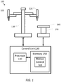
- FIG. 1 is a simplified diagram of a computer-assisted system 100 according to some embodiments.
- computer-assisted system 100 includes a device 110 with one or more movable or articulated arms 120.
- Each of the one or more articulated arms 120 may support one or more end effectors.
- device 110 may be consistent with a computer-assisted surgical device.
- the one or more articulated arms 120 may each provide support for one or more tools, surgical instruments, imaging devices, and/or the like mounted to a distal end of at least one of the articulated arms 120.
- Device 110 may further be coupled to an operator workstation (not shown), which may include one or more master controls for operating the device 110, the one or more articulated arms 120, and/or the end effectors.
- device 110 and the operator workstation may correspond to a da Vinci® Surgical System commercialized by Intuitive Surgical, Inc. of Sunnyvale, California.
- computer-assisted surgical devices with other configurations, fewer or more articulated arms, and/or the like may be used with computer-assisted system 100.
- Control unit 130 includes a processor 140 coupled to memory 150. Operation of control unit 130 is controlled by processor 140. And although control unit 130 is shown with only one processor 140, it is understood that processor 140 may be representative of one or more central processing units, multi-core processors, microprocessors, microcontrollers, digital signal processors, field programmable gate arrays (FPGAs), application specific integrated circuits (ASICs), and/or the like in control unit 130.
- processor 140 may be representative of one or more central processing units, multi-core processors, microprocessors, microcontrollers, digital signal processors, field programmable gate arrays (FPGAs), application specific integrated circuits (ASICs), and/or the like in control unit 130.
- Control unit 130 may be implemented as a stand-alone subsystem and/or board added to a computing device or as a virtual machine. In some embodiments, control unit may be included as part of the operator workstation and/or operated separately from, but in coordination with the operator workstation.
- Memory 150 may be used to store software executed by control unit 130 and/or one or more data structures used during operation of control unit 130.
- Memory 150 may include one or more types of machine readable media. Some common forms of machine readable media may include floppy disk, flexible disk, hard disk, magnetic tape, any other magnetic medium, CD-ROM, any other optical medium, punch cards, paper tape, any other physical medium with patterns of holes, RAM, PROM, EPROM, FLASH-EPROM, any other memory chip or cartridge, and/or any other medium from which a processor or computer is adapted to read.
- memory 150 includes a motion control application 160 that may be used to support autonomous and/or semiautonomous control of device 110.
- Motion control application 160 may include one or more application programming interfaces (APIs) for receiving position, motion, and/or other sensor information from device 110, exchanging position, motion, and/or collision avoidance information with other control units regarding other devices, such as a surgical table and/or imaging device, and/or planning and/or assisting in the planning of motion for device 110, articulated arms 120, and/or the end effectors of device 110.
- APIs application programming interfaces
- motion control application 160 is depicted as a software application, motion control application 160 may be implemented using hardware, software, and/or a combination of hardware and software.
- computer-assisted system 100 may be found in an operating room and/or an interventional suite. And although computer-assisted system 100 includes only one device 110 with two articulated arms 120, one of ordinary skill would understand that computer-assisted system 100 may include any number of devices with articulated arms and/or end effectors of similar and/or different design from device 110. In some examples, each of the devices may include fewer or more articulated arms and/or end effectors.
- Computer-assisted system 100 further includes a surgical table 170.
- surgical table 170 may support articulated movement of a table top 180 relative to a base of surgical table 170.
- the articulated movement of table top 180 may include support for changing a height, a tilt, a slide, a Trendelenburg orientation, and/or the like of table top 180.
- surgical table 170 may include one or more control inputs, such as a control pendant for controlling the position and/or orientation of table top 180.
- surgical table 170 may correspond to one or more of the operating tables commercialized by Trumpf Medical Systems GmbH of Germany.
- Surgical table 170 may also be coupled to control unit 130 via a corresponding interface.
- the interface may include one or more wireless links, cables, connectors, and/or buses and may further include one or more networks with one or more network switching and/or routing devices.
- surgical table 170 may be coupled to a different control unit than control unit 130.
- motion control application 160 may include one or more application programming interfaces (APIs) for receiving position, motion, and/or other sensor information associated with surgical table 170 and/or table top 180.
- APIs application programming interfaces
- motion control application 160 may plan and/or assist in the planning of motion for surgical table 170 and/or table top 180.
- motion control application 160 may prevent motion of surgical table 170 and/or table top 180, such as by preventing movement of surgical table 170 and/or table top 180 through use of the control pendant.
- motion control application 160 may help register device 110 with surgical table 170 so that a geometric relationship between device 110 and surgical table 170 is known.
- the geometric relationship may include a translation and/or one or more rotations between coordinate frames maintained for device 110 and surgical table 170.
- FIG. 2 is a simplified diagram showing a computer-assisted system 200 according to some embodiments.
- the computer-assisted system 200 may be consistent with computer-assisted system 100.
- the computer-assisted system 200 includes a computer-assisted device 210 with one or more articulated arms and a surgical table 280.
- the computer-assisted device 210 and the surgical table 280 may be coupled together using one or more interfaces and one or more control units so that at least kinematic information about the surgical table 280 is known to the motion control application being used to perform motion of the articulated arms of the computer-assisted device 210.
- the computer-assisted device 210 includes various links and joints.
- the computer-assisted device is generally divided into three different sets of links and joints.
- a set-up structure 220 Starting at the proximal end with a mobile or patient-side cart 215 is a set-up structure 220.
- a series of set-up joints 240 Coupled to a distal end of the set-up structure is a series of set-up joints 240.
- a manipulator 260 such as a universal surgical manipulator.
- the series of set-up joints 240 and manipulator 260 may correspond to one of the articulated arms 120.
- the computer-assisted device is shown with only one series of set-up joints 240 and a corresponding manipulator 260, one of ordinary skill would understand that the computer-assisted device may include more than one series of set-up joints 240 and corresponding manipulators 260 so that the computer-assisted device is equipped with multiple articulated arms.
- the computer-assisted device 210 is mounted on the mobile cart 215.
- the mobile cart 215 enables the computer-assisted device 210 to be transported from location to location, such as between operating rooms or within an operating room to better position the computer-assisted device in proximity to the surgical table 180.
- the set-up structure 220 is mounted on the mobile cart 215.
- the set-up structure 220 includes a two part column including column links 221 and 222. Coupled to the upper or distal end of the column link 222 is a shoulder joint 223. Coupled to the shoulder joint 223 is a two-part boom including boom links 224 and 225. At the distal end of the boom link 225 is a wrist joint 226, and coupled to the wrist joint 226 is an orientation platform 227.
- the links and joints of the set-up structure 220 include various degrees of freedom for changing the position and orientation (i.e., the pose) of the orientation platform 227.
- the two-part column may be used to adjust a height of the orientation platform 227 by moving the shoulder joint 223 up and down along an axis 232.
- the orientation platform 227 may additionally be rotated about the mobile cart 215, the two-part column, and the axis 232 using the shoulder joint 223.
- the horizontal position of the orientation platform 227 may also be adjusted along an axis 234 using the two-part boom.
- the orientation of the orientation platform 227 may also adjusted by rotation about an axis 236 using the wrist joint 226.
- the position of the orientation platform 227 may be adjusted vertically above the mobile cart 215 using the two-part column.
- the positions of the orientation platform 227 may also be adjusted radially and angularly about the mobile cart 215 using the two-part boom and the shoulder joint 223, respectively.
- the angular orientation of the orientation platform 227 may also be changed using the wrist joint 226.
- the orientation platform 227 may be used as a mounting point for one or more articulated arms.
- the ability to adjust the height, horizontal position, and orientation of the orientation platform 227 about the mobile cart 215 provides a flexible set-up structure for positioning and orienting the one or more articulated arms about a work space, such as a patient, located near the mobile cart 215.
- Figure 2 shows a single articulated arm coupled to the orientation platform using a first set-up or flex joint 242. And although only one articulated arm is shown, one of ordinary skill would understand that multiple articulated arms may be coupled to the orientation platform 227 using additional first set-up joints.
- the first set-up joint 242 forms the most proximal portion of the set-up joints 240 section of the articulated arm.
- the set-up joints 240 may further include a series of joints and links. As shown in Figure 2 , the set-up joints 240 include at least links 244 and 246 coupled via one or more joints (not expressly shown).
- the joints and links of the set-up joints 240 include the ability to rotate the set-up joints 240 relative to the orientation platform 227 about an axis 252 using the first set-up joint 242, adjust a radial or horizontal distance between the first set-up joint 242 and the link 246, adjust a height of a manipulator mount 262 at the distal end of link 246 relative to the orientation platform along an axis 254, and rotate the manipulator mount 262 about axis 254.
- the set-up joints 240 may further include additional joints, links, and axes permitting additional degrees of freedom for altering a pose of the manipulator mount 262 relative to the orientation platform 227.
- the manipulator 260 is coupled to the distal end of the set-up joints 240 via the manipulator mount 262.
- the manipulator 260 includes additional joints 264 and links 266 with an instrument carriage 268 mounted at the distal end of the manipulator 260.
- An instrument or manipulator tool 270 is mounted to the instrument carriage 268.
- the tool 270 includes a shaft 272, which is aligned along an insertion axis.
- the shaft 272 is typically aligned so that is passes through a remote center 274 associated with the manipulator 260. Location of the remote center 274 is typically maintained in a fixed translational relationship relative to the manipulator mount 262 so that operation of the joints 264 in the manipulator 260 result in rotations of the shaft 272 about the remote center 274.
- the fixed translational relation of the remote center 274 relative to the manipulator mount 262 is maintained using physical constraints in the joints 264 and links 266 of the manipulator 260, using software constraints placed on the motions permitted for the joints 264, and/or a combination of both.
- the remote center 274 may correspond to a location of a surgical port or incision site in a patient 278 after the manipulator 260 is docked with the patient 278. Because the remote center 274 corresponds to the surgical port, as the tool 270 is used, the remote center 274 remains stationary relative to the patient 278 to limit stresses on the anatomy of the patient 278 at the remote center 274.
- the shaft 272 may be passed through a cannula (not shown) located at the surgical port.
- a tool or tool tip 276 At the distal end of the shaft 272 is a tool or tool tip 276.
- the degrees of freedom in the manipulator 260 due to the joints 264 and the links 266 may permit at least control of the roll, pitch, and yaw of the shaft 272 and/or the tool tip 276 relative to the manipulator mount 262.
- the degrees of freedom in the manipulator 260 may further include the ability to advance and/or retreat the shaft 272 using the instrument carriage 268 so that the tool tip 276 may be advanced and/or retreated along the insertion axis and relative to the remote center 274.
- the manipulator 260 may be consistent with a universal surgical manipulator for use with the da Vinci® Surgical System commercialized by Intuitive Surgical, Inc.
- the tool 270 may be an imaging device such as an endoscope, a gripper, a surgical tool such as a cautery or a scalpel, and/or the like.
- the tool tip 276 may include additional degrees of freedom, such as roll, pitch, yaw, grip, and/or the like that allow for additional localized manipulation of portions of the tool tip 276 relative to the shaft 272.
- the surgical table 280 includes a table base 282 and a table top 284 with the table base 282 being located in proximity to mobile cart 215 so that the instrument 270 and/or tool tip 276 may be manipulated by the computer-assisted device 210 while docked to the patient 278.
- the surgical table 280 further includes an articulated structure 290 that includes one or more joints or links between the table base 282 and the table top 284 so that the relative location of the table top 284, and thus the patient 278, relative to the table base 280 may be controlled.
- the articulated structure 290 may be configured so that the table top 284 is controlled relative to a virtually-defined iso center 286 that may be located at a point above the table top 284.
- iso center 286 may be located within the interior of the patient 278.
- iso center 286 may be collocated with the body wall of the patient at or near one of the port sites, such as a port site corresponding to remote center 274.
- the articulated structure 290 includes a height adjustment joint 292 so that the table top 284 may be raised and/or lowered relative to the table base 282.
- the articulated structure 290 further includes joints and links to change both the tilt 294 and Trendelenburg 296 orientation of the table top 284 relative to the iso center 286.
- the tilt 294 allows the table top 284 to be tilted side-to-side so that either the right or left side of the patient 278 may be rotated upward relative to the other side of the patient 278 (i.e., about a longitudinal or head-to-toe axis of the table top 284).
- the Trendelenburg 296 allows the table top 284 to be rotated so that either the feet of the patient 278 are raised (Trendelenburg) or the head of the patient 278 is raised (reverse Trendelenburg). In some examples, either the tilt 294 and/or the Trendelenburg 296 rotations may be adjusted to generate rotations about iso center 286.
- the articulated structure 290 further includes additional links and joints 298 to slide the table top 284 back and forth relative to the table base 282 with generally a left and/or right motion as depicted in Figure 2 .
- FIG 3 is a simplified diagram of a kinematic model 300 of a computer-assisted medical system according to some embodiments.
- kinematic model 300 may include kinematic information associated with many sources and/or devices.
- the kinematic information may be based on known kinematic models for the links and joints of a computer-assisted medical device and a surgical table.
- the kinematic information may be further based on information associated with the position and/or orientation of the joints of the computer-assisted medical device and the surgical table.
- the information associated with the position and/or orientation of the joints may be derived from one or more sensors, such as encoders, measuring the linear positions of prismatic joints and the rotational positions of revolute joints.
- the kinematic model 300 includes several coordinate frames or coordinate systems and transformations, such as homogeneous transforms, for transforming positions and/or orientation from one of the coordinate frames to another of the coordinate frames.
- the kinematic model 300 may be used to permit the forward and/or reverse mapping of positions and/or orientations in one of the coordinate frames in any other of the coordinate frames by composing the forward and/or reverse/inverse transforms noted by the transform linkages included in Figure 3 .
- the transforms when the transforms are modeled as homogenous transforms in matrix form, the composing may be accomplished using matrix multiplication.
- the kinematic model 300 may be used to model the kinematic relationships of the computer-assisted device 210 and the surgical table 280 of Figure 2 .
- the kinematic model 300 includes a table base coordinate frame 305 that may be used to model a position and/or orientation of a surgical table, such as surgical table 170 and/or surgical table 280.
- the table base coordinate frame 305 may be used to model other points on the surgical table relative to a reference point and/or orientation associated with the surgical table.
- the reference point and/or orientation may be associated with a table base of the surgical table, such as the table base 282.
- the table base coordinate frame 305 may be suitable for use as a world coordinate frame for the computer-assisted system.
- the kinematic model 300 further includes a table top coordinate frame 310 that may be used to model positions and/or orientations in a coordinate frame representative of a table top of the surgical table, such as the table top 284.
- the table top coordinate frame 310 may be centered about a rotational center or iso center of the table top, such as iso center 286.
- the z-axis of the table top coordinate frame 310 may be oriented vertically with respect to a floor or surface on which the surgical table is placed and/or orthogonal to the surface of the table top.
- the x- and y-axes of the table top coordinate frame 310 may be oriented to capture the longitudinal (head to toe) and lateral (side-to-side) major axes of the table top.
- a table base to table top coordinate transform 315 may be used to map positions and/or orientations between the table top coordinate frame 310 and the table base coordinate frame 305.
- one or more kinematic models of an articulated structure of the surgical table, such as articulated structure 290, along with past and/or current joint sensor readings may be used to determine the table base to table top coordinate transform 315.
- the table base to table top coordinate transform 315 may model the composite effect of the height, tilt, Trendelenburg, and/or slide settings associated with the surgical table.
- the kinematic model 300 further includes a device base coordinate frame that may be used to model a position and/or orientation of a computer-assisted device, such as computer-assisted device 110 and/or computer-assisted device 210.
- the device base coordinate frame 320 may be used to model other points on the computer-assisted device relative to a reference point and/or orientation associated with the computer-assisted device.
- the reference point and/or orientation may be associated with a device base of the computer-assisted device, such as the mobile cart 215.
- the device base coordinate frame 320 may be suitable for use as the world coordinate frame for the computer-assisted system.
- the registration may be used to determine a registration transform 325 between the table top coordinate frame 310 and the device base coordinate from 320.
- the registration transform 325 may be a partial or full transform between the table top coordinate frame 310 and the device base coordinate frame 320.
- the registration transform 325 may model just the rotational relationship of the device base to the table base about the z-axis of the table base coordinate frame 305 (e.g., a ⁇ Z registration).
- the registration transform 325 may also model a horizontal offset between the table base coordinate frame 305 and the device base coordinate frame 320 (e.g., a XY registration). This is possible because the computer-assisted device and the surgical table are both positioned on the same horizontal ground plane (the floor) and operated in an upright position.
- height adjustments in the table base to table top transform 315 are analogous to vertical adjustments in the device base coordinate frame 320 because the vertical axes in the table base coordinate frame 305 and the device base coordinate frame 320 are the same or nearly the same so that height differences between the table base coordinate frame 305 and the device base coordinate frame 320 are within a reasonable tolerance of each other.
- the tilt and Trendelenburg adjustments in the table base to table top transform 315 may be mapped to the device base coordinate frame 320 by knowing the height of the table top (or its iso center) and the ⁇ Z and/or XY registration.
- the registration transform 325 and the table base to table top transform 315 may be used to model the computer-assisted surgical device as if it were attached to the table top.
- the kinematic model 300 further includes an arm gantry coordinate frame 330 that may be used as a suitable model for a shared coordinate frame associated with the most proximal points on the articulated arms of the computer-assisted device.
- the arm gantry coordinate frame 330 may be associated with and oriented relative to a convenient point on an arm gantry, such as the orientation platform 227.
- the center point of the arm gantry coordinate frame 330 may be located on the axis 236 with the z-axis aligned with axis 236.
- a device base to arm gantry coordinate transform 335 may be used to map positions and/or orientations between the device base coordinate frame 320 and the arm gantry coordinate frame 330.
- one or more kinematic models of the links and joints of the computer-assisted device between the device base and the arm gantry, such as the set-up structure 220, along with past and/or current joint sensor readings may be used to determine the device base to arm gantry coordinate transform 335.
- the device base to arm gantry coordinate transform 335 may model the composite effect of the two-part column, shoulder joint, two-part boom, and wrist joint of the computer-assisted device.
- the kinematic model 300 further includes a series of coordinate frames and transforms associated with each of the articulated arms of the computer-assisted device. As shown in Figure 3 , the kinematic model 300 includes coordinate frames and transforms for three articulated arms, although one of ordinary skill would understand that different computer-assisted devices may include fewer and/or more articulated arms. Consistent with the configuration of the links and joints of the computer-assisted device 210 of Figure 2 , each of the articulated arms may be modeled using a manipulator mount coordinate frame, a remote center coordinate frame, and a tool or camera coordinate frame, depending on a type of instrument mounted to the distal end of the articulated arm.
- the kinematic relationships of a first one of the articulated arms is captured using a manipulator mount coordinate frame 341, a remote center coordinate frame 342, a tool coordinate frame 343, a gantry to mount transform 344, a mount to remote center transform 345, and a remote center to tool transform 346.
- the manipulator mount coordinate frame 341 represents a suitable model for representing positions and/or orientations associated with a manipulator, such as manipulator 260.
- the manipulator mount coordinate frame 341 is typically associated with a manipulator mount, such as the manipulator mount 262 of the corresponding articulated arm.
- the gantry to mount transform 344 is then based on one or more kinematic models of the links and joints of the computer-assisted device between the arm gantry and the corresponding manipulator mount, such as the corresponding set-up joints 240, along with past and/or current joint sensor readings of the corresponding set-up joints 240.
- the remote center coordinate frame 342 is typically associated with a remote center of the manipulator mounted on the articulated arm, such as the corresponding remote center 274 of the corresponding manipulator 260.
- the mount to remote center transform 345 is then based on one or more kinematic models of the links and joints of the computer-assisted device between the corresponding manipulator mount and the corresponding remote center, such as the corresponding joints 264, corresponding links 266, and corresponding carriage 268 of the corresponding manipulator 260, along with past and/or current joint sensor readings of the corresponding joints 264.
- the mount to remote center transform 345 may include an essentially static translational component and a dynamic rotational component.
- the tool coordinate frame 343 is typically associated with a tool and/or tool tip on an instrument mounted on the articulated arm, such as the corresponding tool 270 and/or tool tip 276.
- the remote center to tool transform 346 is then based on one or more kinematic models of the links and joints of the computer-assisted device that move and/or orient the corresponding tool and the corresponding remote center, along with past and/or current joint sensor readings.
- the remote center to tool transform 346 accounts for the orientation at which the shaft, such as the corresponding shaft 272, passes through the remote center and the distance to which the shaft is advanced and/or retreated relative to the remote center.
- the remote center to tool transform 346 may be constrained to reflect that the insertion axis of the shaft of the tool passes through the remote center and may account for rotations of the shaft and the tool tip about the axis defined by the shaft.
- the kinematic relationships of a second one of the articulated arms is captured using a manipulator mount coordinate frame 351, a remote center coordinate frame 352, a tool coordinate frame 353, a gantry to mount transform 354, a mount to remote center transform 355, and a remote center to tool transform 356.
- the manipulator mount coordinate frame 351 represents a suitable model for representing positions and/or orientations associated with a manipulator, such as manipulator 260.
- the manipulator mount coordinate frame 351 is typically associated with a manipulator mount, such as the manipulator mount 262 of the corresponding articulated arm.
- the gantry to mount transform 354 is then based on one or more kinematic models of the links and joints of the computer-assisted device between the arm gantry and the corresponding manipulator mount, such as the corresponding set-up joints 240, along with past and/or current joint sensor readings of the corresponding set-up joints 240.
- the remote center coordinate frame 352 is typically associated with a remote center of the manipulator mounted on the articulated arm, such as the corresponding remote center 274 of the corresponding manipulator 260.
- the mount to remote center transform 355 is then based on one or more kinematic models of the links and joints of the computer-assisted device between the corresponding manipulator mount and the corresponding remote center, such as the corresponding joints 264, corresponding links 266, and corresponding carriage 268 of the corresponding manipulator 260, along with past and/or current joint sensor readings of the corresponding joints 264.
- the mount to remote center transform 355 may include an essentially static translational component and a dynamic rotational component.
- the tool coordinate frame 353 is typically associated with a tool and/or tool tip on an instrument mounted on the articulated arm, such as the corresponding tool 270 and/or tool tip 276.
- the remote center to tool transform 356 is then based on one or more kinematic models of the links and joints of the computer-assisted device that move and/or orient the corresponding tool and the corresponding remote center, along with past and/or current joint sensor readings.
- the remote center to tool transform 356 accounts for the orientation at which the shaft, such as the corresponding shaft 272, passes through the remote center and the distance to which the shaft is advanced and/or retreated relative to the remote center.
- the remote center to tool transform 356 may be constrained to reflect that the insertion axis of the shaft of the tool passes through the remote center and may account for rotations of the shaft and the tool tip about the insertion axis defined by the shaft.
- the kinematic relationships of a third one of the articulated arms is captured using a manipulator mount coordinate frame 361, a remote center coordinate frame 362, a camera coordinate frame 363, a gantry to mount transform 364, a mount to remote center transform 365, and a remote center to camera transform 366.
- the manipulator mount coordinate frame 361 represents a suitable model for representing positions and/or orientations associated with a manipulator, such as manipulator 260.
- the manipulator mount coordinate frame 361 is typically associated with a manipulator mount, such as the manipulator mount 262 of the corresponding articulated arm.
- the gantry to mount transform 364 is then based on one or more kinematic models of the links and joints of the computer-assisted device between the arm gantry and the corresponding manipulator mount, such as the corresponding set-up joints 240, along with past and/or current joint sensor readings of the corresponding set-up joints 240.
- the remote center coordinate frame 362 is typically associated with a remote center of the manipulator mounted on the articulated arm, such as the corresponding remote center 274 of the corresponding manipulator 260.
- the mount to remote center transform 365 is then based on one or more kinematic models of the links and joints of the computer-assisted device between the corresponding manipulator mount and the corresponding remote center, such as the corresponding joints 264, corresponding links 266, and corresponding carriage 268 of the corresponding manipulator 260, along with past and/or current joint sensor readings of the corresponding joints 264.
- the mount to remote center transform 365 may include an essentially static translational component and a dynamic rotational component.
- the camera coordinate frame 363 is typically associated with an imaging device, such an endoscope, mounted on the articulated arm.
- the remote center to camera transform 366 is then based on one or more kinematic models of the links and joints of the computer-assisted device that move and/or orient the imaging device and the corresponding remote center, along with past and/or current joint sensor readings.
- the remote center to camera transform 366 accounts for the orientation at which the shaft, such as the corresponding shaft 272, passes through the remote center and the distance to which the shaft is advanced and/or retreated relative to the remote center.
- the remote center to camera transform 366 may be constrained to reflect that the insertion axis of the shaft of the imaging device passes through the remote center and may account for rotations of the imaging device about the axis defined by the shaft.
- the registration between the surgical table and the computer-assisted device may be determined between the table top coordinate frame 310 and the device base coordinate frame 320 using an alternative registration transform.
- registration transform 325 may be determined by composing the alternative registration transform with the inverse/reverse of the table base to table top transform 315.
- the coordinate frames and/or transforms used to model the computer-assisted device may be arranged differently dependent on the particular configuration of the links and joints of the computer-assisted device, its articulated arms, its end effectors, its manipulators, and/or its instruments.
- the coordinate frames and transforms of the kinematic model 300 may be used to model coordinate frames and transforms associated with one or more virtual tools and/or virtual cameras.
- the virtual tools and/or cameras may be associated with previously stored and/or latched tool positions, projections of tools and/or cameras due to a motion, reference points defined by a surgeon and/or other personnel, and/or the like.
- a computer-assisted system such as computer-assisted systems 110 and/or 210
- a surgical table such as surgical tables 170 and/or 280
- this may allow for a less time-consuming procedure as surgical table motion may occur without having to undock the manipulators from the patient.
- this may allow a surgeon and/or other medical personnel to monitor organ movement while the surgical table motion is occurring to obtain a more optimal surgical table pose.
- this may also permit active continuation of a surgical procedure during surgical table motion.
- one of the goals is to maintain an appropriate pose for each of the tools and/or tool tips.
- the joints of the surgical table and the joints proximal to each of the manipulators are locked and/or held in place through the use of servo controls and/or brakes so that motion of the joints is limited and/or prohibited entirely. This allows the joints of the manipulators to control the pose of the tools to accomplish a desired procedure without interference from movement in these other joints.
- the manipulators may be docked with a patient during the procedure.
- the pose of the tools and/or tool tips may be controlled via teleoperation by a surgeon at an operator console. It may, however, be desirable to support other modes of operation for the computer-assisted system that allow for movement in the articulated arms while the tools remain docked to the patient. These other modes of operation may introduce risks that are not present in modes of operation when the tools are not docked to the patient. In some examples, these risks may include injury to the patient when the tools and/or tool tips are allowed to move relative to the patient, breach of a sterile field, collisions between the articulated arms, and/or the like.
- these other modes of operation may be characterized by a goal of maintaining a pose of a tool, which is attached to a docked manipulator, relative to a patient when one or more joints proximal to the tool are subject to a disturbance that results in a change to positions and/or orientations (i.e., movements) of the one or more joints.
- a disturbance that results in a change to positions and/or orientations (i.e., movements) of the one or more joints.
- the disturbances associated with these other modes of operation that maintain a pose of a tool may be classified into two general categories.
- the patient to which the manipulator is docked is not moving so that the pose of the tool and/or the tool tip may be monitored and maintained in any suitable world coordinate frame.
- the first category may include disturbances associated with controlled motion of the articulated arm.
- the controlled motion of the articulated arm may include movement in one or more joints used to set-up the articulated arm and/or the manipulator before performing a procedure.
- One example of this includes the movement of one or more joints of the set-up structure of a computer-assisted device consistent with the embodiments of Figure 2 where the orientation platform 227 is translated and aligned to allow the set-up joints 240 be moved to provide good range of motion in the manipulator 260 during a procedure.
- Examples of this type of motion are described in greater detail in unpublished U.S. Provisional Patent Application No. 62/024,887 entitled “System and Method for Aligning with a Reference Target," which was filed on July 15, 2014 and unpublished U.S. Provisional Patent Application No. 61/954,261 entitled “System and Method for Aligning with a Reference Target,” which was filed on March 17, 2014.
- the first category may further include disturbances associated with the release of brakes and/or other joint locks prior to initiating other motion.
- external forces and/or torques on the shaft of the tool such as due to forces and torques applied to the remote center of the manipulator by the body wall of the patient, may result in undesirable motion of the tool and/or the tool tip when the brakes and/or locks are released and forces and/or torques are absorbed by the released joints.
- the first category may further include disturbances caused by operation of the articulated arm in a clutched or float state such as might occur during manual repositioning of the articulated arm by an operator and/or due to a collision between the articulated arm and an obstacle. Examples of this type of motion are described in greater detail in unpublished U.S. Provisional Patent Application No. 61/954,120 entitled “System and Method for Breakaway Clutching in an Articulated Arm,” which was filed on March 17, 2014.
- the patient to whom the manipulator is docked is moving so that the pose of the tool and/or the tool tip may be monitored in a local coordinate frame.
- the second category may include disturbances caused by allowing motion of the articulated structure in the surgical table (i.e., table movement) or movement of the patient relative to the surgical table.
- the orientation of the tool relative to the remote center may begin to change resulting in a change between the pose of tool relative to the patient.
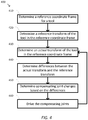
- Figure 4 is a simplified diagram of the method 400 of maintaining the pose of a tool during movement of one or more joints proximal to the tool according to some embodiments.
- One or more of the processes 410-460 of method 400 may be implemented, at least in part, in the form of executable code stored on non-transient, tangible, machine readable media that when run by one or more processors (e.g., the processor 140 in control unit 130) may cause the one or more processors to perform one or more of the processes 410-460.
- method 400 may be used to compensate for changes in the pose of the tool due to motion in one or more disturbed joints by introducing compensating motion in one or more compensating joints.
- method 400 may be used when the motion in the disturbed joints is due to controlled motion, clutched motion, brake or lock release, patient motion, and/or the like.
- the one or more disturbed joints and/or the one or more compensating joints may include any of the joints in set-up structure 220, the set-up joints 240, and/or any joints of manipulator 260 proximal to the tool.
- use of method 400 may be limited to operation when an instrument, cannula, and/or the like is coupled to the distal end of a corresponding articulated arm, end effector, and/or manipulator so that a remote center for the articulated arm, end effector, and/or manipulator may be defined.
- method 400 may include having the pose of the tool at least partially maintained using resistance from a patient port and/or by an operator of the computer-assisted device.
- method 400 may support one or more useful improvements over methods that do not maintain the pose of the tool during movement of the one or more disturbed joints.
- method 400 may reduce the likelihood of collisions between the tool and/or other links and joints of the articulated arm to which the tool is mounted and other articulated arms, end effectors, manipulators, and/or tools whose positions and orientations are known to the computer-assisted device.
- method 400 may reduce the movement of one or more sterile drapes attached to the articulated arm to which the tool is mounted so as to better avoid sweeping and/or moving the one or more sterile drapes into contact with one or more non-sterile obstacles, such as one or more exposed regions of an operator (e.g., the operator's face) and the resultant breach of a sterile field.
- method 400 may reduce the likelihood of moving and/or sweeping the tool and/or the tool tip within the body of the patient so as to reduce the likelihood of injury to the patient by the tool and/or the tool tip.
- a reference coordinate frame for a tool is determined.
- the determination of the reference coordinate frame for the tool depends on an operating mode.
- the determination of the reference frame may further depend on a type of disturbance expected for the articulated arm to which the tool is mounted and/or the one or more joints (i.e., the disturbed joints) that may move as a result of the disturbance.
- the source of the disturbance is associated with a controlled motion of the articulated arm, manual repositioning of the articulated arm, motion induced by a collision of the articulated arm, and/or the like where the patient is not moving and the remote center for the manipulator mounted to the articulated arm is not subject to translation
- any coordinate frame that is fixed relative to a world coordinate frame may be used.
- any of the device base coordinate frame 320, arm gantry coordinate frame 330, and/or remote center coordinate frames 342, 352, and 362 may be used as the reference coordinate frame.
- any coordinate frame that is fixed relative to a world coordinate frame may be used.
- any of the device base coordinate frame 320 and/or arm gantry coordinate frame 330, but not any of the remote center coordinate frames 342, 352, and 362, may be used as the reference coordinate frame.
- a local coordinate frame that moves with the patient may be used.
- the remote center coordinate frame 342, 352, or 362 associated with the articulated arm and/or table top coordinate frame 310 may be used as the reference coordinate frame.
- a reference transform of the tool in the reference coordinate frame is determined.
- one or more kinematic models of the computer-assisted device are used to determine a reference transform for the tool in the reference coordinate frame determined during process 410.
- the one or more kinematic models may include one or more kinematic models for the links and joints of the articulated arm, the manipulator, the tool, the set-up structure and/or the like.
- the reference coordinate frame is the remote center coordinate frame 342, 352, or 362
- the reference coordinate frame is the arm gantry coordinate frame 330
- a cannula and/or a virtual tool may be used to determine the reference transform based on the insertion direction of the cannula and/or a virtual shaft of the instrument.
- an actual transform of the tool in the reference coordinate frame is determined.
- the pose of the tool begins to change because the tool is distal to the one or more disturbed joints.
- the movement of the one or more disturbed joints is monitored and the same one or more kinematic models used during process 420 are again applied using current joint positions and/or orientations to determine the actual transform of the tool in the reference coordinate frame.
- the actual transform represents how the movements of the one or more disturbed joints are tending to move the tool away from the pose that is to be maintained.
- differences between the actual transform and the reference transform are determined.
- the differences between the actual transform and the reference transform represent errors that are being introduced into the pose of the tool by the disturbance. Unless the errors in the pose of the tool are compensated for by movement using one or more compensating joints of the articulate arm, the pose of the tool may undesirably change.
- the differences may be determined by subtracting corresponding matrix and/or vector representations of the actual and reference transforms.
- the differences may be represented as an error transform determined by composing an inverse/reverse of the reference transform with the actual transform.
- compensating joint changes are determined based on the differences.
- changes in the one or more compensating joints are determined.
- the differences between the actual transform and the reference transform are mapped from the reference coordinate system of the actual and reference transforms to one or more local coordinate systems associated with each of the compensating joints. In effect, this transforms the errors in the pose of the tool from the reference coordinate system to errors of the pose relative to the compensating joints.
- one or more kinematic models may be used to transform the differences to the local coordinate systems.
- the compensating joints may include any of the joints of the articulated arm and/or the manipulator that are not one of the disturbed joints.
- the relative errors in the pose may be used to determine the movements for each of the compensating joints.
- an inverse Jacobian may be used to map the relative errors to compensating movements of the compensating joints.
- the movements in the compensating joints may be applied as joint velocities applied to the compensating joints.
- the compensating joints are driven.
- One or more commands are sent to the one or more actuators in the compensating joints based on the movements of the compensating joints determined during process 450.
- the commands sent to the compensating joints correct for the errors in the pose of the tool introduced by the movements in the one or more disturbed joints so that the pose of the tool in the reference coordinate system is maintained with minimal error.
- processes 430-460 are repeated to compensate for any errors introduced into the pose of the tool.
- process 460 may be subject to practical limitations.
- the ability of one or more of the compensating joints to compensate for the errors in the pose of the tool may be limited by range of motion (ROM) limits of the one or more compensating joints.
- ROM range of motion
- method 400 and/or process 460 may be stopped and an error may be indicated to the operator using one or more visible and/or audible error cues.
- process 460 may operate in modified form to partially compensate for the errors in the pose of the tool so as to minimize the controllable error while providing feedback to the operator that not all of the movement caused by the disturbance is being compensated for.
- the feedback may include one or more visible and/or audio cues indicating that compensation is limited and/or the application of resistance on the one or more compensating joints.
- the resistance may include partially applying one or more brakes associated with the one or more compensating joints and/or applying a motion resistance voltage and/or signal in one or more actuators associated with the one or more compensating joints.
- method 400 may be independently applied for each of the tools being manipulated by the computer-assisted device.
- the tools may include any of the tools docked to the patient.
- the compensating joints may be located distal to an arm gantry, such as orientation platform 227, of the computer-assisted device so that compensation to maintain the pose of each of the tools is applied separately for each of the tools.
- the disturbed and compensating joints may not include each of the joints in the articulated arm and/or manipulator.
- the compensating joints may include just the roll, pitch, and yaw joints of the manipulator.
- other joints in the articulated arm and/or the manipulator may be locked to prevent their relative movement during method 400.
- one or more non-actuated joints of the articulated arm and/or the manipulator may be unlocked and/or placed in a clutched and/or float state during method 400 so that errors in the pose of the tool may be at least partially reduced by changes in the unlocked joints.
- the changes in the unlocked joints may reduce the amount that the compensating joints are to be driven.
- the pose of the tool may be at least partially maintained using resistance from the patient port and/or by an operator of the computer-assisted device.
- one or more of the processes 430-460 may be performed concurrently.
- additional conditions may result in premature termination of method 400 such as by returning control of the computer-assisted device to an operator and/or by suspension of operation of the computer-assisted device.
- the additional conditions may include inability to complete the compensated movement, manual intervention and/or override from an operator using one or more controls on an operator workstation and/or the articulated arms, detection of operator disengagement with the operator workstation using one or more safety interlocks, position tracking errors in the computer-assisted device, system faults, and/or the like.
- the desired movement may not be possible due to the detection of imminent collisions among the links and/or joints of the computer-assisted device, range of motion limits in one or more of the joints of the computer-assisted device, inability to maintain the pose of the tool due to motion of the patient, and/or the like.
- premature termination of method 400 may result in an error notification being sent to the operator.
- the error notification may include any visual and/or audible indicator, such as a text message, a blinking light, an audible tone, a spoken phrase, and/or the like.
- control units such as control unit 130 may include non-transient, tangible, machine readable media that include executable code that when run by one or more processors (e.g., processor 140) may cause the one or more processors to perform the processes of method 400.
- processors e.g., processor 140
- Some common forms of machine readable media that may include the processes of method 400 are, for example, floppy disk, flexible disk, hard disk, magnetic tape, any other magnetic medium, CD-ROM, any other optical medium, punch cards, paper tape, any other physical medium with patterns of holes, RAM, PROM, EPROM, FLASH-EPROM, any other memory chip or cartridge, and/or any other medium from which a processor or computer is adapted to read.
Landscapes
- Health & Medical Sciences (AREA)
- Engineering & Computer Science (AREA)
- Life Sciences & Earth Sciences (AREA)
- Surgery (AREA)
- Robotics (AREA)
- Public Health (AREA)
- Veterinary Medicine (AREA)
- General Health & Medical Sciences (AREA)
- Animal Behavior & Ethology (AREA)
- Biomedical Technology (AREA)
- Medical Informatics (AREA)
- Nuclear Medicine, Radiotherapy & Molecular Imaging (AREA)
- Molecular Biology (AREA)
- Heart & Thoracic Surgery (AREA)
- Mechanical Engineering (AREA)
- Physics & Mathematics (AREA)
- Pathology (AREA)
- Radiology & Medical Imaging (AREA)
- Biophysics (AREA)
- Optics & Photonics (AREA)
- Mathematical Physics (AREA)
- Automation & Control Theory (AREA)
- Manipulator (AREA)
- Oral & Maxillofacial Surgery (AREA)
- Endoscopes (AREA)
Description
- The present disclosure relates generally to operation of devices with articulated arms and more particularly to maintaining a tool pose.
- More and more devices are being replaced with autonomous and semiautonomous electronic devices. This is especially true in the hospitals of today with large arrays of autonomous and semiautonomous electronic devices being found in operating rooms, interventional suites, intensive care wards, emergency rooms, and the like. For example, glass and mercury thermometers are being replaced with electronic thermometers, intravenous drip lines now include electronic monitors and flow regulators, and traditional hand-held surgical instruments are being replaced by computer-assisted medical devices.
- These electronic devices provide both advantages and challenges to the personnel operating them. Many of these electronic devices may be capable of autonomous or semiautonomous motion of one or more articulated arms and/or end effectors. These one or more articulated arms and/or end effectors each include a combination of links and articulated joints that support motion of the articulated arms and/or end effectors. In many cases, the articulated joints are manipulated to obtain a desired position and/or orientation (collectively, a desired pose) of a corresponding tool located at a distal end of the links and articulated joints of a corresponding articulated arm and/or end effector. Each of the articulated joints proximal to the tool provides the corresponding articulated arm and/or end effector with at least one degree of freedom that may be used to manipulate the position and/or orientation of the corresponding tool. In many cases, the corresponding articulated arms and/or end effectors may include at least six degrees of freedom that allow for controlling a x, y, and z position of the corresponding tool as well as a roll, pitch, and yaw orientation of the corresponding tool. To provide for greater flexibility in control of the pose of the corresponding tool, the corresponding articulated arms and/or end effectors are often designed to include redundant degrees of freedom. When redundant degrees of freedom are present it is possible that multiple different combinations of positions and/or orientations of the articulated joints may be used to obtain the same pose of the corresponding tool. This creates a null space where even though the articulated joints are moving, the pose of the corresponding tool is not.
- As each of the articulated arms and/or end effectors is being operated, the articulated arm and/or end effector may be subject to motion, both planned and unplanned, that may result in movement in one or more of the articulated joints. As this motion changes the positions and/or orientations of the one or more articulated joints, the changes may introduce undesirable alteration to the pose of a tool being manipulated by the articulated arm. This alteration to the pose may result in injury to a patient, injury to personnel in proximity to the articulated arms and/or end effectors, damage to the articulated arms and/or end effectors, damage to other devices in proximity to the articulated arms and/or end effectors, breach of a sterile field, and/or other undesirable outcomes.
-
US 2011/0276059 A1 discloses telerobotic, telesurgical, and/or surgical robotic devices, systems, and methods which employ surgical robotic linkages that may have more degrees of freedom than an associated surgical end effector n space. A processor can calculate a tool motion that includes pivoting of the tool about an aperture site. Linkages movable along a range of configurations for a given end effector position may be driven toward configurations which inhibit collisions. -
EP 1 234 641 A1 discloses a robot controller for keeping the posture of a tool in a task coordinate system by a simple processing and allowing a robot to perform flexible translational motion. A robot controller for controlling a motor for driving a joint by means of a control circuit having a position/speed state feedback loop, comprising means for measuring the angle of a joint of a robot, means for storing the initial posture of a tool attached to the end of a hand of the robot, means for setting the position or speed gain of a specific joint axis smaller than the position or speed gains of the other joint axes, and means for calculating the correction of a position or speed command to keep the tool posture with respect to the robot base on the basis of the angle of the joint and the initial posture of the tool. -
EP 1 642 690 A2 discloses a method for controlling the trajectory of a robot, in which, in the cooperative operation of a leading robot having a work tool and a tracking robot gripping a workpiece, the position and the orientation of the work tool may be desirably controlled, even when the interpolative motion is carried out. The robots are cooperatively controlled such that the position and the orientation of a first tool coordinate system set on the work tool attached to the leading robot is moved along a desired trajectory on a second tool coordinate system set on the workpiece gripped by the tracking robot. During a playback operation after a teaching operation, the interpolative position data of the tracking robot is calculated by using the interpolative position data of the leading robot and the relative positions and the relative orientations data of the robots. The invention may be applied to a manual feed. The trajectory may be smoothed by filtering the interpolative position data. -
US 5,465,037 A discloses a system and method for seam tracking in real time without path preprogramming uses at least two degrees of freedom and at least one degree of freedom created by a redundant axis. A robot can be used to weld or apply adhesive or sealant to a workpiece that is mounted on a positioner that it is movable relative to a base of the robot as a movable end of the robot tracks a seam on the workpiece. A sensor expresses a seam trajectory in workpiece coordinates and queues the coordinates in a computer processor so that the coordinates can be extracted from the processor to cause the movable end of the robot to track the seam. The workpiece can remain stationary and the robot base can be moved or the base can remain stationary and the workpiece can be moved or both the workpiece and the robot base can be moved. Any reasonable number of redundant axes can be utilized so long as there is one control parameter independently defined for each degree of freedom greater than six. Previous seam tracking systems do not have more than one degree of freedom with one of the degrees of freedom being created by redundant axes and previous systems do not automatically move the robot base relative to the workpiece -
DE102008041602A1 discloses a device for maintaining the orientation and position of a robotic tool using redundant joints. - Accordingly, it would be desirable to maintain a pose of a tool in the presence of disturbances in articulated joints located proximal to the tool.
- The invention is defined in independent claims 1 and 11, preferred embodiments are described in the dependent claims.
- The present invention provides a computer-assisted medical device comprising: an articulated arm comprising one or more first joints and one or more second joints, the articulated arm configured to hold a tool distal to the one or more first joints and the one or more second joints; and a control unit coupled to the one or more first joints and the one or more second joints; wherein, during movement of the one or more first joints, the control unit maintains a position and an orientation of the tool using the one or more second joints by: determining a reference coordinate frame for the tool; determining a reference transform of the tool in the reference coordinate frame prior to the movement of the one or more first joints; determining an actual transform of the tool in the reference coordinate frame while the one or more first joints are being moved; determining differences between the reference transform and the actual transform; and maintaining the position and orientation of the tool by driving the one or more second joints based on the differences.
- Consistent with some examples, a method of compensating for motion in an articulated arm of a computer-assisted medical device includes determining a pose of a tool of the medical device and maintaining the pose of the tool during movement of one or more first joints of an articulated arm proximal to the tool using one or more second joints proximal to the tool. The pose is maintained by determining a reference coordinate frame for the tool, determining a reference transform of the tool in the reference coordinate frame prior to the movement of the one or more first joints, determining an actual transform of the tool in the reference coordinate frame while the one or more first joints are being moved, determining differences between the reference transform and the actual transform, and maintaining the pose of the tool by driving the second joints based on the differences. The pose includes a position and an orientation.
- The present invention also provides a non-transitory machine-readable medium including a plurality of machine-readable instructions which when executed by one or more processors associated with_a computer-assisted medical device are adapted to cause the one or more processors to perform a method comprising: determining a position and orientation of a tool of the computer-assisted medical device; and during movement of one or more first joints of an articulated arm proximal to the tool, maintaining the position and orientation of the tool using one or more second joints proximal to the tool by: determining a reference coordinate frame for the tool; determining a reference transform of the tool in the reference coordinate frame prior to the movement of the one or more first joints; determining an actual transform of the tool in the reference coordinate frame while the one or more first joints are being moved; determining differences between the reference transform and the actual transform; and maintaining the position and orientation of the tool by driving the second joints based on the differences.
-
-
Figure 1 is a simplified diagram of a computer-assisted system according to some embodiments. -
Figure 2 is a simplified diagram showing a computer-assisted system according to some embodiments. -
Figure 3 is a simplified diagram of a kinematic model of a computer-assisted medical system according to some embodiments. -
Figure 4 is a simplified diagram of the method of maintaining the pose of a tool during movement of one or more joints proximal to the tool according to some embodiments. - In the figures, elements having the same designations have the same or similar functions.
- In the following description, specific details are set forth describing some embodiments consistent with the present disclosure. It will be apparent to one skilled in the art, however, that some embodiments may be practiced without some or all of these specific details. The specific embodiments disclosed herein are meant to be illustrative but not limiting. One skilled in the art may realize other elements that, although not specifically described here, are within the scope of this disclosure. In addition, to avoid unnecessary repetition, one or more features shown and described in association with one embodiment may be incorporated into other embodiments unless specifically described otherwise or if the one or more features would make an embodiment non-functional.
-
Figure 1 is a simplified diagram of a computer-assistedsystem 100 according to some embodiments. As shown inFigure 1 , computer-assistedsystem 100 includes adevice 110 with one or more movable or articulatedarms 120. Each of the one or morearticulated arms 120 may support one or more end effectors. In some examples,device 110 may be consistent with a computer-assisted surgical device. The one or more articulatedarms 120 may each provide support for one or more tools, surgical instruments, imaging devices, and/or the like mounted to a distal end of at least one of the articulatedarms 120.Device 110 may further be coupled to an operator workstation (not shown), which may include one or more master controls for operating thedevice 110, the one or more articulatedarms 120, and/or the end effectors. In some embodiments,device 110 and the operator workstation may correspond to a da Vinci® Surgical System commercialized by Intuitive Surgical, Inc. of Sunnyvale, California. In some embodiments, computer-assisted surgical devices with other configurations, fewer or more articulated arms, and/or the like may be used with computer-assistedsystem 100. -
Device 110 is coupled to acontrol unit 130 via an interface. The interface may include one or more wireless links, cables, connectors, and/or buses and may further include one or more networks with one or more network switching and/or routing devices.Control unit 130 includes aprocessor 140 coupled tomemory 150. Operation ofcontrol unit 130 is controlled byprocessor 140. And althoughcontrol unit 130 is shown with only oneprocessor 140, it is understood thatprocessor 140 may be representative of one or more central processing units, multi-core processors, microprocessors, microcontrollers, digital signal processors, field programmable gate arrays (FPGAs), application specific integrated circuits (ASICs), and/or the like incontrol unit 130.Control unit 130 may be implemented as a stand-alone subsystem and/or board added to a computing device or as a virtual machine. In some embodiments, control unit may be included as part of the operator workstation and/or operated separately from, but in coordination with the operator workstation. -
Memory 150 may be used to store software executed bycontrol unit 130 and/or one or more data structures used during operation ofcontrol unit 130.Memory 150 may include one or more types of machine readable media. Some common forms of machine readable media may include floppy disk, flexible disk, hard disk, magnetic tape, any other magnetic medium, CD-ROM, any other optical medium, punch cards, paper tape, any other physical medium with patterns of holes, RAM, PROM, EPROM, FLASH-EPROM, any other memory chip or cartridge, and/or any other medium from which a processor or computer is adapted to read. - As shown,
memory 150 includes amotion control application 160 that may be used to support autonomous and/or semiautonomous control ofdevice 110.Motion control application 160 may include one or more application programming interfaces (APIs) for receiving position, motion, and/or other sensor information fromdevice 110, exchanging position, motion, and/or collision avoidance information with other control units regarding other devices, such as a surgical table and/or imaging device, and/or planning and/or assisting in the planning of motion fordevice 110, articulatedarms 120, and/or the end effectors ofdevice 110. And althoughmotion control application 160 is depicted as a software application,motion control application 160 may be implemented using hardware, software, and/or a combination of hardware and software. - In some embodiments, computer-assisted
system 100 may be found in an operating room and/or an interventional suite. And although computer-assistedsystem 100 includes only onedevice 110 with two articulatedarms 120, one of ordinary skill would understand that computer-assistedsystem 100 may include any number of devices with articulated arms and/or end effectors of similar and/or different design fromdevice 110. In some examples, each of the devices may include fewer or more articulated arms and/or end effectors. - Computer-assisted
system 100 further includes a surgical table 170. Like the one or more articulatedarms 120, surgical table 170 may support articulated movement of atable top 180 relative to a base of surgical table 170. In some examples, the articulated movement oftable top 180 may include support for changing a height, a tilt, a slide, a Trendelenburg orientation, and/or the like oftable top 180. Although not shown, surgical table 170 may include one or more control inputs, such as a control pendant for controlling the position and/or orientation oftable top 180. In some embodiments, surgical table 170 may correspond to one or more of the operating tables commercialized by Trumpf Medical Systems GmbH of Germany. - Surgical table 170 may also be coupled to control
unit 130 via a corresponding interface. The interface may include one or more wireless links, cables, connectors, and/or buses and may further include one or more networks with one or more network switching and/or routing devices. In some embodiments, surgical table 170 may be coupled to a different control unit thancontrol unit 130. In some examples,motion control application 160 may include one or more application programming interfaces (APIs) for receiving position, motion, and/or other sensor information associated with surgical table 170 and/ortable top 180. In some examples,motion control application 160 may plan and/or assist in the planning of motion for surgical table 170 and/ortable top 180. In some examples,motion control application 160 may prevent motion of surgical table 170 and/ortable top 180, such as by preventing movement of surgical table 170 and/ortable top 180 through use of the control pendant. In some examples,motion control application 160 may help registerdevice 110 with surgical table 170 so that a geometric relationship betweendevice 110 and surgical table 170 is known. In some examples, the geometric relationship may include a translation and/or one or more rotations between coordinate frames maintained fordevice 110 and surgical table 170. -
Figure 2 is a simplified diagram showing a computer-assistedsystem 200 according to some embodiments. For example, the computer-assistedsystem 200 may be consistent with computer-assistedsystem 100. As shown inFigure 2 , the computer-assistedsystem 200 includes a computer-assisted device 210 with one or more articulated arms and a surgical table 280. Although not shown inFigure 2 , the computer-assisted device 210 and the surgical table 280 may be coupled together using one or more interfaces and one or more control units so that at least kinematic information about the surgical table 280 is known to the motion control application being used to perform motion of the articulated arms of the computer-assisted device 210. - The computer-assisted device 210 includes various links and joints. In the embodiments of
Figure 2 , the computer-assisted device is generally divided into three different sets of links and joints. Starting at the proximal end with a mobile or patient-side cart 215 is a set-upstructure 220. Coupled to a distal end of the set-up structure is a series of set-upjoints 240. And coupled to a distal end of the set-upjoints 240 is amanipulator 260, such as a universal surgical manipulator. In some examples, the series of set-upjoints 240 andmanipulator 260 may correspond to one of the articulatedarms 120. And although the computer-assisted device is shown with only one series of set-upjoints 240 and acorresponding manipulator 260, one of ordinary skill would understand that the computer-assisted device may include more than one series of set-upjoints 240 andcorresponding manipulators 260 so that the computer-assisted device is equipped with multiple articulated arms. - As shown, the computer-assisted device 210 is mounted on the
mobile cart 215. Themobile cart 215 enables the computer-assisted device 210 to be transported from location to location, such as between operating rooms or within an operating room to better position the computer-assisted device in proximity to the surgical table 180. The set-upstructure 220 is mounted on themobile cart 215. As shown inFigure 2 , the set-upstructure 220 includes a two part column includingcolumn links column link 222 is ashoulder joint 223. Coupled to theshoulder joint 223 is a two-part boom includingboom links boom link 225 is a wrist joint 226, and coupled to the wrist joint 226 is anorientation platform 227. - The links and joints of the set-up
structure 220 include various degrees of freedom for changing the position and orientation (i.e., the pose) of theorientation platform 227. For example, the two-part column may be used to adjust a height of theorientation platform 227 by moving theshoulder joint 223 up and down along anaxis 232. Theorientation platform 227 may additionally be rotated about themobile cart 215, the two-part column, and theaxis 232 using theshoulder joint 223. The horizontal position of theorientation platform 227 may also be adjusted along anaxis 234 using the two-part boom. And the orientation of theorientation platform 227 may also adjusted by rotation about anaxis 236 using thewrist joint 226. Thus, subject to the motion limits of the links and joints in the set-upstructure 220, the position of theorientation platform 227 may be adjusted vertically above themobile cart 215 using the two-part column. The positions of theorientation platform 227 may also be adjusted radially and angularly about themobile cart 215 using the two-part boom and theshoulder joint 223, respectively. And the angular orientation of theorientation platform 227 may also be changed using thewrist joint 226. - The
orientation platform 227 may be used as a mounting point for one or more articulated arms. The ability to adjust the height, horizontal position, and orientation of theorientation platform 227 about themobile cart 215 provides a flexible set-up structure for positioning and orienting the one or more articulated arms about a work space, such as a patient, located near themobile cart 215.Figure 2 shows a single articulated arm coupled to the orientation platform using a first set-up or flex joint 242. And although only one articulated arm is shown, one of ordinary skill would understand that multiple articulated arms may be coupled to theorientation platform 227 using additional first set-up joints. - The first set-up joint 242 forms the most proximal portion of the set-up
joints 240 section of the articulated arm. The set-upjoints 240 may further include a series of joints and links. As shown inFigure 2 , the set-upjoints 240 include atleast links joints 240 include the ability to rotate the set-upjoints 240 relative to theorientation platform 227 about anaxis 252 using the first set-up joint 242, adjust a radial or horizontal distance between the first set-up joint 242 and thelink 246, adjust a height of amanipulator mount 262 at the distal end oflink 246 relative to the orientation platform along anaxis 254, and rotate themanipulator mount 262 aboutaxis 254. In some examples, the set-upjoints 240 may further include additional joints, links, and axes permitting additional degrees of freedom for altering a pose of themanipulator mount 262 relative to theorientation platform 227. - The
manipulator 260 is coupled to the distal end of the set-upjoints 240 via themanipulator mount 262. Themanipulator 260 includesadditional joints 264 andlinks 266 with aninstrument carriage 268 mounted at the distal end of themanipulator 260. An instrument ormanipulator tool 270 is mounted to theinstrument carriage 268. Thetool 270 includes ashaft 272, which is aligned along an insertion axis. Theshaft 272 is typically aligned so that is passes through aremote center 274 associated with themanipulator 260. Location of theremote center 274 is typically maintained in a fixed translational relationship relative to themanipulator mount 262 so that operation of thejoints 264 in themanipulator 260 result in rotations of theshaft 272 about theremote center 274. Depending upon the embodiment, the fixed translational relation of theremote center 274 relative to themanipulator mount 262 is maintained using physical constraints in thejoints 264 andlinks 266 of themanipulator 260, using software constraints placed on the motions permitted for thejoints 264, and/or a combination of both. In some examples, theremote center 274 may correspond to a location of a surgical port or incision site in apatient 278 after themanipulator 260 is docked with thepatient 278. Because theremote center 274 corresponds to the surgical port, as thetool 270 is used, theremote center 274 remains stationary relative to thepatient 278 to limit stresses on the anatomy of thepatient 278 at theremote center 274. In some examples, theshaft 272 may be passed through a cannula (not shown) located at the surgical port. - At the distal end of the
shaft 272 is a tool ortool tip 276. The degrees of freedom in themanipulator 260 due to thejoints 264 and thelinks 266 may permit at least control of the roll, pitch, and yaw of theshaft 272 and/or thetool tip 276 relative to themanipulator mount 262. In some examples, the degrees of freedom in themanipulator 260 may further include the ability to advance and/or retreat theshaft 272 using theinstrument carriage 268 so that thetool tip 276 may be advanced and/or retreated along the insertion axis and relative to theremote center 274. In some examples, themanipulator 260 may be consistent with a universal surgical manipulator for use with the da Vinci® Surgical System commercialized by Intuitive Surgical, Inc. of Sunnyvale, California. In some examples, thetool 270 may be an imaging device such as an endoscope, a gripper, a surgical tool such as a cautery or a scalpel, and/or the like. In some examples, thetool tip 276 may include additional degrees of freedom, such as roll, pitch, yaw, grip, and/or the like that allow for additional localized manipulation of portions of thetool tip 276 relative to theshaft 272. - During a surgery or other medical procedure, the
patient 278 is typically located on the surgical table 280. The surgical table 280 includes atable base 282 and atable top 284 with thetable base 282 being located in proximity tomobile cart 215 so that theinstrument 270 and/ortool tip 276 may be manipulated by the computer-assisted device 210 while docked to thepatient 278. The surgical table 280 further includes an articulatedstructure 290 that includes one or more joints or links between thetable base 282 and thetable top 284 so that the relative location of thetable top 284, and thus thepatient 278, relative to thetable base 280 may be controlled. In some examples, the articulatedstructure 290 may be configured so that thetable top 284 is controlled relative to a virtually-definediso center 286 that may be located at a point above thetable top 284. In some examples,iso center 286 may be located within the interior of thepatient 278. In some examples,iso center 286 may be collocated with the body wall of the patient at or near one of the port sites, such as a port site corresponding toremote center 274. - As shown in
Figure 2 , the articulatedstructure 290 includes a height adjustment joint 292 so that thetable top 284 may be raised and/or lowered relative to thetable base 282. The articulatedstructure 290 further includes joints and links to change both thetilt 294 andTrendelenburg 296 orientation of thetable top 284 relative to theiso center 286. Thetilt 294 allows thetable top 284 to be tilted side-to-side so that either the right or left side of thepatient 278 may be rotated upward relative to the other side of the patient 278 (i.e., about a longitudinal or head-to-toe axis of the table top 284). TheTrendelenburg 296 allows thetable top 284 to be rotated so that either the feet of thepatient 278 are raised (Trendelenburg) or the head of thepatient 278 is raised (reverse Trendelenburg). In some examples, either thetilt 294 and/or theTrendelenburg 296 rotations may be adjusted to generate rotations aboutiso center 286. The articulatedstructure 290 further includes additional links andjoints 298 to slide thetable top 284 back and forth relative to thetable base 282 with generally a left and/or right motion as depicted inFigure 2 . -
Figure 3 is a simplified diagram of akinematic model 300 of a computer-assisted medical system according to some embodiments. As shown inFigure 3 ,kinematic model 300 may include kinematic information associated with many sources and/or devices. The kinematic information may be based on known kinematic models for the links and joints of a computer-assisted medical device and a surgical table. The kinematic information may be further based on information associated with the position and/or orientation of the joints of the computer-assisted medical device and the surgical table. In some examples, the information associated with the position and/or orientation of the joints may be derived from one or more sensors, such as encoders, measuring the linear positions of prismatic joints and the rotational positions of revolute joints. - The
kinematic model 300 includes several coordinate frames or coordinate systems and transformations, such as homogeneous transforms, for transforming positions and/or orientation from one of the coordinate frames to another of the coordinate frames. In some examples, thekinematic model 300 may be used to permit the forward and/or reverse mapping of positions and/or orientations in one of the coordinate frames in any other of the coordinate frames by composing the forward and/or reverse/inverse transforms noted by the transform linkages included inFigure 3 . In some examples, when the transforms are modeled as homogenous transforms in matrix form, the composing may be accomplished using matrix multiplication. In some embodiments, thekinematic model 300 may be used to model the kinematic relationships of the computer-assisted device 210 and the surgical table 280 ofFigure 2 . - The
kinematic model 300 includes a table base coordinateframe 305 that may be used to model a position and/or orientation of a surgical table, such as surgical table 170 and/or surgical table 280. In some examples, the table base coordinateframe 305 may be used to model other points on the surgical table relative to a reference point and/or orientation associated with the surgical table. In some examples, the reference point and/or orientation may be associated with a table base of the surgical table, such as thetable base 282. In some examples, the table base coordinateframe 305 may be suitable for use as a world coordinate frame for the computer-assisted system. - The
kinematic model 300 further includes a table top coordinateframe 310 that may be used to model positions and/or orientations in a coordinate frame representative of a table top of the surgical table, such as thetable top 284. In some examples, the table top coordinateframe 310 may be centered about a rotational center or iso center of the table top, such asiso center 286. In some examples, the z-axis of the table top coordinateframe 310 may be oriented vertically with respect to a floor or surface on which the surgical table is placed and/or orthogonal to the surface of the table top. In some examples, the x- and y-axes of the table top coordinateframe 310 may be oriented to capture the longitudinal (head to toe) and lateral (side-to-side) major axes of the table top. In some examples, a table base to table top coordinatetransform 315 may be used to map positions and/or orientations between the table top coordinateframe 310 and the table base coordinateframe 305. In some examples, one or more kinematic models of an articulated structure of the surgical table, such as articulatedstructure 290, along with past and/or current joint sensor readings may be used to determine the table base to table top coordinatetransform 315. In some examples consistent with the embodiments ofFigure 2 , the table base to table top coordinatetransform 315 may model the composite effect of the height, tilt, Trendelenburg, and/or slide settings associated with the surgical table. - The
kinematic model 300 further includes a device base coordinate frame that may be used to model a position and/or orientation of a computer-assisted device, such as computer-assisteddevice 110 and/or computer-assisted device 210. In some examples, the device base coordinateframe 320 may be used to model other points on the computer-assisted device relative to a reference point and/or orientation associated with the computer-assisted device. In some examples, the reference point and/or orientation may be associated with a device base of the computer-assisted device, such as themobile cart 215. In some examples, the device base coordinateframe 320 may be suitable for use as the world coordinate frame for the computer-assisted system. - In order to track positional and/or orientational relationships between the surgical table and the computer-assisted device, it may be desirable to perform a registration between the surgical table and the computer-assisted device. As shown in
Figure 3 , the registration may be used to determine aregistration transform 325 between the table top coordinateframe 310 and the device base coordinate from 320. In some embodiments, theregistration transform 325 may be a partial or full transform between the table top coordinateframe 310 and the device base coordinateframe 320. In some examples, because the table base and the device base are typically located on the same level floor surface, theregistration transform 325 may model just the rotational relationship of the device base to the table base about the z-axis of the table base coordinate frame 305 (e.g., a θZ registration). In some examples, theregistration transform 325 may also model a horizontal offset between the table base coordinateframe 305 and the device base coordinate frame 320 (e.g., a XY registration). This is possible because the computer-assisted device and the surgical table are both positioned on the same horizontal ground plane (the floor) and operated in an upright position. In this operational relationship, height adjustments in the table base to tabletop transform 315 are analogous to vertical adjustments in the device base coordinateframe 320 because the vertical axes in the table base coordinateframe 305 and the device base coordinateframe 320 are the same or nearly the same so that height differences between the table base coordinateframe 305 and the device base coordinateframe 320 are within a reasonable tolerance of each other. In some examples, the tilt and Trendelenburg adjustments in the table base to tabletop transform 315 may be mapped to the device base coordinateframe 320 by knowing the height of the table top (or its iso center) and the θZ and/or XY registration. In some examples, theregistration transform 325 and the table base to tabletop transform 315 may be used to model the computer-assisted surgical device as if it were attached to the table top. - The
kinematic model 300 further includes an arm gantry coordinateframe 330 that may be used as a suitable model for a shared coordinate frame associated with the most proximal points on the articulated arms of the computer-assisted device. In some embodiments, the arm gantry coordinateframe 330 may be associated with and oriented relative to a convenient point on an arm gantry, such as theorientation platform 227. In some examples, the center point of the arm gantry coordinateframe 330 may be located on theaxis 236 with the z-axis aligned withaxis 236. In some examples, a device base to arm gantry coordinatetransform 335 may be used to map positions and/or orientations between the device base coordinateframe 320 and the arm gantry coordinateframe 330. In some examples, one or more kinematic models of the links and joints of the computer-assisted device between the device base and the arm gantry, such as the set-upstructure 220, along with past and/or current joint sensor readings may be used to determine the device base to arm gantry coordinatetransform 335. In some examples consistent with the embodiments ofFigure 2 , the device base to arm gantry coordinatetransform 335 may model the composite effect of the two-part column, shoulder joint, two-part boom, and wrist joint of the computer-assisted device. - The
kinematic model 300 further includes a series of coordinate frames and transforms associated with each of the articulated arms of the computer-assisted device. As shown inFigure 3 , thekinematic model 300 includes coordinate frames and transforms for three articulated arms, although one of ordinary skill would understand that different computer-assisted devices may include fewer and/or more articulated arms. Consistent with the configuration of the links and joints of the computer-assisted device 210 ofFigure 2 , each of the articulated arms may be modeled using a manipulator mount coordinate frame, a remote center coordinate frame, and a tool or camera coordinate frame, depending on a type of instrument mounted to the distal end of the articulated arm. - In the
kinematic model 300, the kinematic relationships of a first one of the articulated arms is captured using a manipulator mount coordinateframe 341, a remote center coordinateframe 342, a tool coordinateframe 343, a gantry to mounttransform 344, a mount to remote center transform 345, and a remote center to tool transform 346. The manipulator mount coordinateframe 341 represents a suitable model for representing positions and/or orientations associated with a manipulator, such asmanipulator 260. The manipulator mount coordinateframe 341 is typically associated with a manipulator mount, such as themanipulator mount 262 of the corresponding articulated arm. The gantry to mounttransform 344 is then based on one or more kinematic models of the links and joints of the computer-assisted device between the arm gantry and the corresponding manipulator mount, such as the corresponding set-upjoints 240, along with past and/or current joint sensor readings of the corresponding set-upjoints 240. - The remote center coordinate
frame 342 is typically associated with a remote center of the manipulator mounted on the articulated arm, such as the correspondingremote center 274 of thecorresponding manipulator 260. The mount to remote center transform 345 is then based on one or more kinematic models of the links and joints of the computer-assisted device between the corresponding manipulator mount and the corresponding remote center, such as the correspondingjoints 264, correspondinglinks 266, andcorresponding carriage 268 of thecorresponding manipulator 260, along with past and/or current joint sensor readings of the corresponding joints 264. When the corresponding remote center is being maintained in fixed positional relationship to the corresponding manipulator mounts, such as in the embodiments ofFigure 2 , the mount to remote center transform 345 may include an essentially static translational component and a dynamic rotational component. - The tool coordinate
frame 343 is typically associated with a tool and/or tool tip on an instrument mounted on the articulated arm, such as thecorresponding tool 270 and/ortool tip 276. The remote center to tool transform 346 is then based on one or more kinematic models of the links and joints of the computer-assisted device that move and/or orient the corresponding tool and the corresponding remote center, along with past and/or current joint sensor readings. In some examples, the remote center to tool transform 346 accounts for the orientation at which the shaft, such as the correspondingshaft 272, passes through the remote center and the distance to which the shaft is advanced and/or retreated relative to the remote center. In some examples, the remote center to tool transform 346 may be constrained to reflect that the insertion axis of the shaft of the tool passes through the remote center and may account for rotations of the shaft and the tool tip about the axis defined by the shaft. - In the
kinematic model 300, the kinematic relationships of a second one of the articulated arms is captured using a manipulator mount coordinateframe 351, a remote center coordinateframe 352, a tool coordinateframe 353, a gantry to mounttransform 354, a mount to remote center transform 355, and a remote center to tool transform 356. The manipulator mount coordinateframe 351 represents a suitable model for representing positions and/or orientations associated with a manipulator, such asmanipulator 260. The manipulator mount coordinateframe 351 is typically associated with a manipulator mount, such as themanipulator mount 262 of the corresponding articulated arm. The gantry to mounttransform 354 is then based on one or more kinematic models of the links and joints of the computer-assisted device between the arm gantry and the corresponding manipulator mount, such as the corresponding set-upjoints 240, along with past and/or current joint sensor readings of the corresponding set-upjoints 240. - The remote center coordinate
frame 352 is typically associated with a remote center of the manipulator mounted on the articulated arm, such as the correspondingremote center 274 of thecorresponding manipulator 260. The mount to remote center transform 355 is then based on one or more kinematic models of the links and joints of the computer-assisted device between the corresponding manipulator mount and the corresponding remote center, such as the correspondingjoints 264, correspondinglinks 266, andcorresponding carriage 268 of thecorresponding manipulator 260, along with past and/or current joint sensor readings of the corresponding joints 264. When the corresponding remote center is being maintained in fixed positional relationship to the corresponding manipulator mounts, such as in the embodiments ofFigure 2 , the mount to remote center transform 355 may include an essentially static translational component and a dynamic rotational component. - The tool coordinate
frame 353 is typically associated with a tool and/or tool tip on an instrument mounted on the articulated arm, such as thecorresponding tool 270 and/ortool tip 276. The remote center to tool transform 356 is then based on one or more kinematic models of the links and joints of the computer-assisted device that move and/or orient the corresponding tool and the corresponding remote center, along with past and/or current joint sensor readings. In some examples, the remote center to tool transform 356 accounts for the orientation at which the shaft, such as the correspondingshaft 272, passes through the remote center and the distance to which the shaft is advanced and/or retreated relative to the remote center. In some examples, the remote center to tool transform 356 may be constrained to reflect that the insertion axis of the shaft of the tool passes through the remote center and may account for rotations of the shaft and the tool tip about the insertion axis defined by the shaft. - In the
kinematic model 300, the kinematic relationships of a third one of the articulated arms is captured using a manipulator mount coordinateframe 361, a remote center coordinateframe 362, a camera coordinateframe 363, a gantry to mounttransform 364, a mount to remote center transform 365, and a remote center to camera transform 366. The manipulator mount coordinateframe 361 represents a suitable model for representing positions and/or orientations associated with a manipulator, such asmanipulator 260. The manipulator mount coordinateframe 361 is typically associated with a manipulator mount, such as themanipulator mount 262 of the corresponding articulated arm. The gantry to mounttransform 364 is then based on one or more kinematic models of the links and joints of the computer-assisted device between the arm gantry and the corresponding manipulator mount, such as the corresponding set-upjoints 240, along with past and/or current joint sensor readings of the corresponding set-upjoints 240. - The remote center coordinate
frame 362 is typically associated with a remote center of the manipulator mounted on the articulated arm, such as the correspondingremote center 274 of thecorresponding manipulator 260. The mount to remote center transform 365 is then based on one or more kinematic models of the links and joints of the computer-assisted device between the corresponding manipulator mount and the corresponding remote center, such as the correspondingjoints 264, correspondinglinks 266, andcorresponding carriage 268 of thecorresponding manipulator 260, along with past and/or current joint sensor readings of the corresponding joints 264. When the corresponding remote center is being maintained in fixed positional relationship to the corresponding manipulator mounts, such as in the embodiments ofFigure 2 , the mount to remote center transform 365 may include an essentially static translational component and a dynamic rotational component. - The camera coordinate
frame 363 is typically associated with an imaging device, such an endoscope, mounted on the articulated arm. The remote center to camera transform 366 is then based on one or more kinematic models of the links and joints of the computer-assisted device that move and/or orient the imaging device and the corresponding remote center, along with past and/or current joint sensor readings. In some examples, the remote center to camera transform 366 accounts for the orientation at which the shaft, such as the correspondingshaft 272, passes through the remote center and the distance to which the shaft is advanced and/or retreated relative to the remote center. In some examples, the remote center to camera transform 366 may be constrained to reflect that the insertion axis of the shaft of the imaging device passes through the remote center and may account for rotations of the imaging device about the axis defined by the shaft. - As discussed above and further emphasized here,
Figure 3 is merely an example which should not unduly limit the scope of the claims. One of ordinary skill in the art would recognize many variations, alternatives, and modifications. According to some embodiments, the registration between the surgical table and the computer-assisted device may be determined between the table top coordinateframe 310 and the device base coordinateframe 320 using an alternative registration transform. When the alternative registration transform is used, registration transform 325 may be determined by composing the alternative registration transform with the inverse/reverse of the table base to tabletop transform 315. According to some embodiments, the coordinate frames and/or transforms used to model the computer-assisted device may be arranged differently dependent on the particular configuration of the links and joints of the computer-assisted device, its articulated arms, its end effectors, its manipulators, and/or its instruments. According to some embodiments, the coordinate frames and transforms of thekinematic model 300 may be used to model coordinate frames and transforms associated with one or more virtual tools and/or virtual cameras. In some examples, the virtual tools and/or cameras may be associated with previously stored and/or latched tool positions, projections of tools and/or cameras due to a motion, reference points defined by a surgeon and/or other personnel, and/or the like. - As described previously, as a computer-assisted system, such as computer-assisted
systems 110 and/or 210, is being operated it would be desirable to allow continued control of the tool and/or tool tips while motion of a surgical table, such as surgical tables 170 and/or 280, is allowed. In some examples, this may allow for a less time-consuming procedure as surgical table motion may occur without having to undock the manipulators from the patient. In some examples, this may allow a surgeon and/or other medical personnel to monitor organ movement while the surgical table motion is occurring to obtain a more optimal surgical table pose. In some examples, this may also permit active continuation of a surgical procedure during surgical table motion. - As a computer-assisted system, such as computer-assisted
systems 110 and/or 200 are being operated, one of the goals is to maintain an appropriate pose for each of the tools and/or tool tips. In one mode of operation for the computer-assisted system, the joints of the surgical table and the joints proximal to each of the manipulators are locked and/or held in place through the use of servo controls and/or brakes so that motion of the joints is limited and/or prohibited entirely. This allows the joints of the manipulators to control the pose of the tools to accomplish a desired procedure without interference from movement in these other joints. In some examples, the manipulators may be docked with a patient during the procedure. In some examples, the pose of the tools and/or tool tips may be controlled via teleoperation by a surgeon at an operator console. It may, however, be desirable to support other modes of operation for the computer-assisted system that allow for movement in the articulated arms while the tools remain docked to the patient. These other modes of operation may introduce risks that are not present in modes of operation when the tools are not docked to the patient. In some examples, these risks may include injury to the patient when the tools and/or tool tips are allowed to move relative to the patient, breach of a sterile field, collisions between the articulated arms, and/or the like. - In a general case, these other modes of operation may be characterized by a goal of maintaining a pose of a tool, which is attached to a docked manipulator, relative to a patient when one or more joints proximal to the tool are subject to a disturbance that results in a change to positions and/or orientations (i.e., movements) of the one or more joints. Because disturbances in one or more first or disturbed joints proximal to a tool results in a change in the pose of the tool and its tool tip, it may be desirable to introduce movement in one or more second or compensating joints that compensate for the changes in the pose of the tool caused by the movement of the disturbed joints. Determining the extent of the disturbance and the amount of compensation depends on the type and nature of the disturbance, such as whether the disturbance is associated with movement of the surgical table or patient, or whether the disturbance is confined to the articulated arm used to manipulate the tool.
- The disturbances associated with these other modes of operation that maintain a pose of a tool may be classified into two general categories. In the first category, the patient to which the manipulator is docked is not moving so that the pose of the tool and/or the tool tip may be monitored and maintained in any suitable world coordinate frame. The first category may include disturbances associated with controlled motion of the articulated arm. In some examples, the controlled motion of the articulated arm may include movement in one or more joints used to set-up the articulated arm and/or the manipulator before performing a procedure. One example of this includes the movement of one or more joints of the set-up structure of a computer-assisted device consistent with the embodiments of
Figure 2 where theorientation platform 227 is translated and aligned to allow the set-upjoints 240 be moved to provide good range of motion in themanipulator 260 during a procedure. Examples of this type of motion are described in greater detail in unpublished U.S. Provisional Patent Application No.62/024,887 61/954,261 61/954,120 - In the second category, the patient to whom the manipulator is docked is moving so that the pose of the tool and/or the tool tip may be monitored in a local coordinate frame. The second category may include disturbances caused by allowing motion of the articulated structure in the surgical table (i.e., table movement) or movement of the patient relative to the surgical table. In the second category, it is generally desired to have the articulated arm and the tool move with the patient so that the pose of the tool relative to the patient does not change. In some examples, this may be accomplished using port dragging that may include releasing and/or unlocking one or more joints of the articulated arm and allowing the body wall of the patient at the port to drag the remote center and the tool as the patient moves. In some examples, as the remote center moves the orientation of the tool relative to the remote center may begin to change resulting in a change between the pose of tool relative to the patient.
-
Figure 4 is a simplified diagram of themethod 400 of maintaining the pose of a tool during movement of one or more joints proximal to the tool according to some embodiments. One or more of the processes 410-460 ofmethod 400 may be implemented, at least in part, in the form of executable code stored on non-transient, tangible, machine readable media that when run by one or more processors (e.g., theprocessor 140 in control unit 130) may cause the one or more processors to perform one or more of the processes 410-460. In some embodiments,method 400 may be used to compensate for changes in the pose of the tool due to motion in one or more disturbed joints by introducing compensating motion in one or more compensating joints. In some examples,method 400 may be used when the motion in the disturbed joints is due to controlled motion, clutched motion, brake or lock release, patient motion, and/or the like. In some examples consistent with the embodiments ofFigure 2 , the one or more disturbed joints and/or the one or more compensating joints may include any of the joints in set-upstructure 220, the set-upjoints 240, and/or any joints ofmanipulator 260 proximal to the tool. In some embodiments, use ofmethod 400 may be limited to operation when an instrument, cannula, and/or the like is coupled to the distal end of a corresponding articulated arm, end effector, and/or manipulator so that a remote center for the articulated arm, end effector, and/or manipulator may be defined. In some embodiments,method 400 may include having the pose of the tool at least partially maintained using resistance from a patient port and/or by an operator of the computer-assisted device. - According to some embodiments,
method 400 may support one or more useful improvements over methods that do not maintain the pose of the tool during movement of the one or more disturbed joints. In some examples,method 400 may reduce the likelihood of collisions between the tool and/or other links and joints of the articulated arm to which the tool is mounted and other articulated arms, end effectors, manipulators, and/or tools whose positions and orientations are known to the computer-assisted device. In some examples,method 400 may reduce the movement of one or more sterile drapes attached to the articulated arm to which the tool is mounted so as to better avoid sweeping and/or moving the one or more sterile drapes into contact with one or more non-sterile obstacles, such as one or more exposed regions of an operator (e.g., the operator's face) and the resultant breach of a sterile field. In some examples,method 400 may reduce the likelihood of moving and/or sweeping the tool and/or the tool tip within the body of the patient so as to reduce the likelihood of injury to the patient by the tool and/or the tool tip. - At a
process 410, a reference coordinate frame for a tool is determined. The determination of the reference coordinate frame for the tool depends on an operating mode. In some examples, the determination of the reference frame may further depend on a type of disturbance expected for the articulated arm to which the tool is mounted and/or the one or more joints (i.e., the disturbed joints) that may move as a result of the disturbance. When the source of the disturbance is associated with a controlled motion of the articulated arm, manual repositioning of the articulated arm, motion induced by a collision of the articulated arm, and/or the like where the patient is not moving and the remote center for the manipulator mounted to the articulated arm is not subject to translation, any coordinate frame that is fixed relative to a world coordinate frame may be used. Consistent with the embodiments ofFigures 2 and3 , any of the device base coordinateframe 320, arm gantry coordinateframe 330, and/or remote center coordinateframes Figures 2 and3 , any of the device base coordinateframe 320 and/or arm gantry coordinateframe 330, but not any of the remote center coordinateframes Figures 2 and3 , the remote center coordinateframe frame 310 may be used as the reference coordinate frame. - At a
process 420, a reference transform of the tool in the reference coordinate frame is determined. Prior to the initiation of movement of the one or more disturbed joints, one or more kinematic models of the computer-assisted device are used to determine a reference transform for the tool in the reference coordinate frame determined duringprocess 410. In some examples, the one or more kinematic models may include one or more kinematic models for the links and joints of the articulated arm, the manipulator, the tool, the set-up structure and/or the like. Using the embodiments ofFigures 2 and3 as an example, when the reference coordinate frame is the remote center coordinateframe camera transform frame 330, a composition of the corresponding gantry to mounttransform camera transform - At a
process 430, an actual transform of the tool in the reference coordinate frame is determined. As the one or more disturbed joints begin to move due to the disturbance, the pose of the tool begins to change because the tool is distal to the one or more disturbed joints. The movement of the one or more disturbed joints is monitored and the same one or more kinematic models used duringprocess 420 are again applied using current joint positions and/or orientations to determine the actual transform of the tool in the reference coordinate frame. The actual transform represents how the movements of the one or more disturbed joints are tending to move the tool away from the pose that is to be maintained. - At a
process 440, differences between the actual transform and the reference transform are determined. The differences between the actual transform and the reference transform represent errors that are being introduced into the pose of the tool by the disturbance. Unless the errors in the pose of the tool are compensated for by movement using one or more compensating joints of the articulate arm, the pose of the tool may undesirably change. In some examples, the differences may be determined by subtracting corresponding matrix and/or vector representations of the actual and reference transforms. In some examples, the differences may be represented as an error transform determined by composing an inverse/reverse of the reference transform with the actual transform. - At a
process 450, compensating joint changes are determined based on the differences. Using the differences between the actual transform and the reference transform determined duringprocess 440, changes in the one or more compensating joints are determined. The differences between the actual transform and the reference transform are mapped from the reference coordinate system of the actual and reference transforms to one or more local coordinate systems associated with each of the compensating joints. In effect, this transforms the errors in the pose of the tool from the reference coordinate system to errors of the pose relative to the compensating joints. In some examples, one or more kinematic models may be used to transform the differences to the local coordinate systems. In some examples, the compensating joints may include any of the joints of the articulated arm and/or the manipulator that are not one of the disturbed joints. Once the relative errors in the pose are determined, they may be used to determine the movements for each of the compensating joints. In some examples, an inverse Jacobian may be used to map the relative errors to compensating movements of the compensating joints. In some examples, the movements in the compensating joints may be applied as joint velocities applied to the compensating joints. - At a
process 460, the compensating joints are driven. One or more commands are sent to the one or more actuators in the compensating joints based on the movements of the compensating joints determined duringprocess 450. The commands sent to the compensating joints correct for the errors in the pose of the tool introduced by the movements in the one or more disturbed joints so that the pose of the tool in the reference coordinate system is maintained with minimal error. As long as the one or more compensating joints continue to make corrective changes to the pose of the tool, processes 430-460 are repeated to compensate for any errors introduced into the pose of the tool. - According to some embodiments,
process 460 may be subject to practical limitations. In some examples, the ability of one or more of the compensating joints to compensate for the errors in the pose of the tool may be limited by range of motion (ROM) limits of the one or more compensating joints. In some examples, when a ROM limit for one or more of the compensating joints is reached and/or is about to be reachedmethod 400 and/orprocess 460 may be stopped and an error may be indicated to the operator using one or more visible and/or audible error cues. In some examples, rather than stopping operation ofmethod 400 and/orprocess 460,process 460 may operate in modified form to partially compensate for the errors in the pose of the tool so as to minimize the controllable error while providing feedback to the operator that not all of the movement caused by the disturbance is being compensated for. In some examples, the feedback may include one or more visible and/or audio cues indicating that compensation is limited and/or the application of resistance on the one or more compensating joints. In some examples, the resistance may include partially applying one or more brakes associated with the one or more compensating joints and/or applying a motion resistance voltage and/or signal in one or more actuators associated with the one or more compensating joints. - As discussed above and further emphasized here,
Figure 4 is merely an example which should not unduly limit the scope of the claims. One of ordinary skill in the art would recognize many variations, alternatives, and modifications. According to some embodiments,method 400 may be independently applied for each of the tools being manipulated by the computer-assisted device. In some examples, the tools may include any of the tools docked to the patient. In some examples, the compensating joints may be located distal to an arm gantry, such asorientation platform 227, of the computer-assisted device so that compensation to maintain the pose of each of the tools is applied separately for each of the tools. - According to some embodiments, the disturbed and compensating joints may not include each of the joints in the articulated arm and/or manipulator. In some examples, the compensating joints may include just the roll, pitch, and yaw joints of the manipulator. In some examples, other joints in the articulated arm and/or the manipulator may be locked to prevent their relative movement during
method 400. In some examples, one or more non-actuated joints of the articulated arm and/or the manipulator may be unlocked and/or placed in a clutched and/or float state duringmethod 400 so that errors in the pose of the tool may be at least partially reduced by changes in the unlocked joints. In some examples, the changes in the unlocked joints may reduce the amount that the compensating joints are to be driven. In some examples, the pose of the tool may be at least partially maintained using resistance from the patient port and/or by an operator of the computer-assisted device. - According to some embodiments, one or more of the processes 430-460 may be performed concurrently. According to some embodiments, additional conditions may result in premature termination of
method 400 such as by returning control of the computer-assisted device to an operator and/or by suspension of operation of the computer-assisted device. In some examples, the additional conditions may include inability to complete the compensated movement, manual intervention and/or override from an operator using one or more controls on an operator workstation and/or the articulated arms, detection of operator disengagement with the operator workstation using one or more safety interlocks, position tracking errors in the computer-assisted device, system faults, and/or the like. In some examples, the desired movement may not be possible due to the detection of imminent collisions among the links and/or joints of the computer-assisted device, range of motion limits in one or more of the joints of the computer-assisted device, inability to maintain the pose of the tool due to motion of the patient, and/or the like. In some examples, premature termination ofmethod 400 may result in an error notification being sent to the operator. In some examples, the error notification may include any visual and/or audible indicator, such as a text message, a blinking light, an audible tone, a spoken phrase, and/or the like. - Some examples of control units, such as
control unit 130 may include non-transient, tangible, machine readable media that include executable code that when run by one or more processors (e.g., processor 140) may cause the one or more processors to perform the processes ofmethod 400. Some common forms of machine readable media that may include the processes ofmethod 400 are, for example, floppy disk, flexible disk, hard disk, magnetic tape, any other magnetic medium, CD-ROM, any other optical medium, punch cards, paper tape, any other physical medium with patterns of holes, RAM, PROM, EPROM, FLASH-EPROM, any other memory chip or cartridge, and/or any other medium from which a processor or computer is adapted to read. - The scope of the invention should be limited only by the following claims.
Claims (15)
- A computer-assisted medical device (110, 210) comprising:an articulated arm (120) comprising one or more first joints (223, 226, 242, 264) and one or more second joints (223, 226, 242, 264), the articulated arm (120) configured to hold a tool (270) distal to the one or more first joints (223, 226, 242, 264) and the one or more second joints (223, 226, 242, 264); anda control unit (130) coupled to the one or more first joints (223, 226, 242, 264) and the one or more second joints (223, 226, 242, 264);characterized in that, during movement of the one or more first joints (223, 226, 242, 264), the control unit (130) maintains a position and an orientation of the tool (270) using the one or more second joints (223, 226, 242, 264) by:determining a reference coordinate frame (320, 330, 342, 352, 362) for the tool (270);determining a reference transform of the tool (270) in the reference coordinate frame (320, 330, 342, 352, 362) prior to the movement of the one or more first joints (223, 226, 242, 264);determining an actual transform of the tool (270) in the reference coordinate frame (320, 330, 342, 352, 362) while the one or more first joints (223, 226, 242, 264) are being moved;determining differences between the reference transform and the actual transform; andmaintaining the position and orientation of the tool (270) by driving the one or more second joints (223, 226, 242, 264) based on the differences.
- The device (110, 210) of claim 1, wherein the control unit (130) further maintains the position and the orientation of the tool (270) by converting the differences to a second coordinate frame local to the one or more second joints (223, 226, 242, 264).
- The device (110, 210) of claim 1, wherein the control unit (130) further maintains the position and the orientation of the tool (270) by determining commands for the one or more second joints (223, 226, 242, 264) based on an inverse Jacobian for the one or more second joints (223, 226, 242, 264).
- The device (110, 210) of any of claims 1-3, wherein the control unit (130) further maintains the position and the orientation of the tool (270) by determining the reference transform and the actual transform based on positions of the one or more first joints (223, 226, 242, 264), positions of the one or more second joints (223, 226, 242, 264), and one or more kinematic models of the computer-assisted medical device (110, 210).
- The device (110, 210) of any of claims 1-3, wherein the one or more second joints (223, 226, 242, 264) are configured to control a roll, a pitch, and a yaw of the tool (270) relative to the reference coordinate frame (320, 330, 342, 352, 362).
- The device (110, 210) of any of claims 1-3, wherein the control unit (130) further maintains the position and the orientation of the tool (270) by determining the reference coordinate frame (320, 330, 342, 352, 362) for the tool (270) based on a cause of the movement of the one or more first joints (223, 226, 242, 264).
- The device (110, 210) of claim 6, wherein when the movement of the one or more first joints (223, 226, 242, 264) is due to controlled motion of the articulated arm (120), manual repositioning of the articulated arm (120), or motion induced by a collision of the articulated arm (120), the reference coordinate frame (320, 330, 342, 352, 362) is fixed relative to a world coordinate frame of the computer-assisted medical device (110, 210).
- The device (110, 210) of claim 6, wherein when the movement of the one or more first joints (223, 226, 242, 264) is due to release of one or more brakes or locks of the one or more first joints (223, 226, 242, 264), the reference coordinate frame (320, 330, 342, 352, 362) is fixed relative to a world coordinate frame of the computer-assisted medical device (110,210).
- The device (110, 210) of claim 6, wherein when the movement of the one or more first joints (223, 226, 242, 264) is due to movement of a patient, the reference coordinate frame (320, 330, 342, 352, 362) is associated with a remote center (274) of the articulated arm (120), and
wherein the movement of the patient is due to movement of a surgical table (170, 280). - The device (110, 210) of any of claims 1-3, wherein each of the one or more second joints (223, 226, 242, 264) is associated with a manipulator of the articulated arm (120),
wherein each of the one or more second joints (223, 226, 242, 264) is distal to each of the one or more first joints (223, 226, 242, 264), and
wherein the control unit (130) determines the differences between the reference transform and the actual transform by composing an inverse of the reference transform with the actual transform. - A non-transitory machine-readable medium including a plurality of machine-readable instructions which when executed by one or more processors associated with the computer-assisted medical device (110, 210) of claim 1 are adapted to cause the one or more processors to perform a method comprising:determining a pose of a tool (270) of the computer-assisted medical device (110, 210), the pose including a position and an orientation; andduring movement of one or more first joints (223, 226, 242, 264) of an articulated arm (120) proximal to the tool (270), maintaining the pose of the tool (270) using one or more second joints (223, 226, 242, 264) proximal to the tool (270) by:determining a reference coordinate frame (320, 330, 342, 352, 362) for the tool (270);determining a reference transform of the tool in the reference coordinate frame prior to the movement of the one or more first joints (223, 226, 242, 264);determining an actual transform of the tool (270) in the reference coordinate frame (320, 330, 342, 352, 362) while the one or more first joints (223, 226, 242, 264) are being moved;determining differences between the reference transform and the actual transform; andmaintaining the pose of the tool (270) by driving the second joints (223, 226, 242, 264) based on the differences.
- The non-transitory machine-readable medium of claim 11, wherein maintaining the position and orientation of the tool (270) comprises converting the differences to a second coordinate frame local to the second joints (223, 226, 242, 264).
- The non-transitory machine-readable medium of claim 11 or 12, wherein when the movement of the one or more first joints (223, 226, 242, 264) is due to movement of a patient, the reference coordinate frame (320, 330, 342, 352, 362) is associated with a remote center (274) of the articulated arm (120).
- The non-transitory machine-readable medium of claim 11 or 12, wherein the reference coordinate frame (320, 330, 342, 352, 362) is fixed relative to a world coordinate frame of the computer-assisted medical device (110, 210) when the movement of the one or more first joints (223, 226, 242, 264) is due to a cause selected from a group of causes consisting of: controlled motion of the articulated arm (120), manual repositioning of the articulated arm (120), motion induced by a collision of the articulated arm (120), and release of one or more brakes or locks of the one or more first joints (223, 226, 242, 264).
- The non-transitory machine-readable medium of claim 11 or 12, wherein maintaining the pose of the tool (270) comprises determining the reference coordinate frame (320, 330, 342, 352, 362) for the tool (270) based on a cause of the movement of the one or more first joints (223, 226, 242, 264).
Priority Applications (1)
| Application Number | Priority Date | Filing Date | Title |
|---|---|---|---|
| EP21166255.6A EP3868326A1 (en) | 2014-03-17 | 2015-03-17 | System and method for maintaining a tool pose |
Applications Claiming Priority (3)
| Application Number | Priority Date | Filing Date | Title |
|---|---|---|---|
| US201461954261P | 2014-03-17 | 2014-03-17 | |
| US201462024887P | 2014-07-15 | 2014-07-15 | |
| PCT/US2015/021089 WO2015142943A1 (en) | 2014-03-17 | 2015-03-17 | System and method for maintaining a tool pose |
Related Child Applications (2)
| Application Number | Title | Priority Date | Filing Date |
|---|---|---|---|
| EP21166255.6A Division-Into EP3868326A1 (en) | 2014-03-17 | 2015-03-17 | System and method for maintaining a tool pose |
| EP21166255.6A Division EP3868326A1 (en) | 2014-03-17 | 2015-03-17 | System and method for maintaining a tool pose |
Publications (3)
| Publication Number | Publication Date |
|---|---|
| EP3119342A1 EP3119342A1 (en) | 2017-01-25 |
| EP3119342A4 EP3119342A4 (en) | 2017-11-15 |
| EP3119342B1 true EP3119342B1 (en) | 2021-05-12 |
Family
ID=54145241
Family Applications (3)
| Application Number | Title | Priority Date | Filing Date |
|---|---|---|---|
| EP15765922.8A Active EP3119342B1 (en) | 2014-03-17 | 2015-03-17 | System for maintaining a tool pose |
| EP15765353.6A Active EP3119333B1 (en) | 2014-03-17 | 2015-03-17 | System for aligning with a reference target |
| EP21166255.6A Pending EP3868326A1 (en) | 2014-03-17 | 2015-03-17 | System and method for maintaining a tool pose |
Family Applications After (2)
| Application Number | Title | Priority Date | Filing Date |
|---|---|---|---|
| EP15765353.6A Active EP3119333B1 (en) | 2014-03-17 | 2015-03-17 | System for aligning with a reference target |
| EP21166255.6A Pending EP3868326A1 (en) | 2014-03-17 | 2015-03-17 | System and method for maintaining a tool pose |
Country Status (6)
| Country | Link |
|---|---|
| US (7) | US10070931B2 (en) |
| EP (3) | EP3119342B1 (en) |
| JP (5) | JP6537523B2 (en) |
| KR (5) | KR102541266B1 (en) |
| CN (4) | CN110251233B (en) |
| WO (2) | WO2015142943A1 (en) |
Families Citing this family (59)
| Publication number | Priority date | Publication date | Assignee | Title |
|---|---|---|---|---|
| JP6512216B2 (en) * | 2014-03-14 | 2019-05-15 | ソニー株式会社 | Robot arm device, robot arm control method and program |
| KR102541266B1 (en) | 2014-03-17 | 2023-06-13 | 인튜어티브 서지컬 오퍼레이션즈 인코포레이티드 | System and method for maintaining a tool pose |
| CN110584789B (en) | 2014-10-27 | 2022-09-20 | 直观外科手术操作公司 | System and method for instrument interference compensation |
| EP3912610B1 (en) | 2014-10-27 | 2023-03-15 | Intuitive Surgical Operations, Inc. | System for registering to a surgical table |
| US10226306B2 (en) | 2014-10-27 | 2019-03-12 | Intuitive Surgical Operations, Inc. | System and method for integrated surgical table |
| CN107072746B (en) | 2014-10-27 | 2020-06-09 | 直观外科手术操作公司 | System and method for integrating surgical table icons |
| KR102623373B1 (en) | 2014-10-27 | 2024-01-11 | 인튜어티브 서지컬 오퍼레이션즈 인코포레이티드 | System and method for integrated surgical table motion |
| CN107072728B (en) | 2014-10-27 | 2020-07-17 | 直观外科手术操作公司 | System and method for monitoring control points during reactive motion |
| KR102480765B1 (en) | 2014-10-27 | 2022-12-23 | 인튜어티브 서지컬 오퍼레이션즈 인코포레이티드 | Medical device with active brake release control |
| TR201511033A2 (en) * | 2015-09-04 | 2017-03-21 | Melih Cakmakci | A motion system. |
| JP2017104451A (en) * | 2015-12-11 | 2017-06-15 | 川崎重工業株式会社 | Surgical system |
| DE102015225183B4 (en) * | 2015-12-15 | 2022-09-15 | Carl Zeiss Meditec Ag | Medical device with a medical-optical device and a holding device and method for operating the medical device |
| JP6657933B2 (en) * | 2015-12-25 | 2020-03-04 | ソニー株式会社 | Medical imaging device and surgical navigation system |
| CN108289719B (en) | 2016-01-20 | 2021-09-14 | 直观外科手术操作公司 | System and method for rapidly pausing and resuming motion deviation in a medical device repositionable arm |
| CN108430372B (en) * | 2016-01-29 | 2022-01-18 | 直观外科手术操作公司 | System and method for variable speed surgical instrument |
| WO2017147596A1 (en) | 2016-02-26 | 2017-08-31 | Think Surgical, Inc. | Method and system for guiding user positioning of a robot |
| WO2018053282A1 (en) | 2016-09-16 | 2018-03-22 | GYS Tech, LLC d/b/a Cardan Robotics | System and method for mounting a robotic arm in a surgical robotic system |
| CN109310473B (en) * | 2016-09-19 | 2023-02-17 | 直观外科手术操作公司 | Base positioning system for a controllable arm and related method |
| CN110114019B (en) * | 2016-12-08 | 2022-04-12 | 安托踏实公司 | Surgical system for cutting an anatomical structure according to at least one target plane |
| US11607229B2 (en) | 2016-12-08 | 2023-03-21 | Orthotaxy S.A.S. | Surgical system for cutting an anatomical structure according to at least one target plane |
| EP3551098B1 (en) | 2016-12-08 | 2024-03-20 | Orthotaxy | Surgical system for cutting an anatomical structure according to at least one target cutting plane |
| WO2018165320A1 (en) * | 2017-03-07 | 2018-09-13 | Intuitive Surgical Operations, Inc. | Systems and methods for controlling tool with articulatable distal portion |
| CN107374727B (en) * | 2017-07-28 | 2019-10-22 | 重庆金山医疗器械有限公司 | A kind of minimally invasive surgical operation robot simplifies the modeling method of kinematics model |
| CN107389011A (en) * | 2017-09-01 | 2017-11-24 | 凯里市浪金科技有限责任公司 | It is a kind of can multi-faceted measurement coordinate measuring set |
| EP3703604A4 (en) | 2017-10-30 | 2021-08-11 | Intuitive Surgical Operations, Inc. | Systems and methods for guided port placement selection |
| CN108210070B (en) * | 2017-12-29 | 2020-04-10 | 微创(上海)医疗机器人有限公司 | Mechanical arm, working method thereof and surgical robot |
| CN110269685B (en) * | 2018-03-14 | 2021-02-19 | 深圳市精锋医疗科技有限公司 | Connecting assembly, operation arm, slave operation equipment and operation robot for minimally invasive surgery |
| CN108338841B (en) * | 2018-04-17 | 2021-03-23 | 成都博恩思医学机器人有限公司 | Laparoscopic surgery holds mirror robot system |
| WO2019218157A1 (en) * | 2018-05-15 | 2019-11-21 | 深圳市亚泰光电技术有限公司 | Endoscope steering adjustment method and endoscope |
| CN109124773A (en) * | 2018-06-25 | 2019-01-04 | 深圳市精锋医疗科技有限公司 | mechanical arm |
| CN109124772A (en) * | 2018-06-25 | 2019-01-04 | 深圳市精锋医疗科技有限公司 | From operation equipment |
| CN109223183A (en) * | 2018-09-30 | 2019-01-18 | 深圳市精锋医疗科技有限公司 | Starting method, readable access to memory and the operating robot of operating robot |
| CN109316235B (en) * | 2018-10-10 | 2021-04-30 | 江西欧德医疗器材有限公司 | Intelligent spicule control system and using method |
| CN113453819B (en) * | 2019-01-18 | 2024-03-15 | 诺冠自动化解决方案有限责任公司 | Method and device for automatically switching tool system |
| JP7153335B2 (en) * | 2019-01-29 | 2022-10-14 | リバーフィールド株式会社 | Surgery support device |
| US20220175472A1 (en) * | 2019-03-29 | 2022-06-09 | Intuitive Surgical Operations, Inc. | Reducing energy buildup in servo-controlled mechanisms |
| KR102150495B1 (en) * | 2019-04-26 | 2020-09-01 | 주식회사 골프존 | Swing machine and control method for the same |
| KR20220004950A (en) | 2019-05-01 | 2022-01-12 | 인튜어티브 서지컬 오퍼레이션즈 인코포레이티드 | Systems and Methods for Imaging Devices and Integrated Motion |
| WO2021026779A1 (en) * | 2019-08-13 | 2021-02-18 | 深圳市大疆创新科技有限公司 | Cradle head control method and device, cradle head and storage medium |
| CN110559083B (en) * | 2019-09-10 | 2020-08-25 | 深圳市精锋医疗科技有限公司 | Surgical robot and control method and control device for tail end instrument of surgical robot |
| US20230012535A1 (en) * | 2019-12-05 | 2023-01-19 | Kawasaki Jukogyo Kabushiki Kaisha | Surgical robot, surgical system, and control method |
| CN111035452B (en) * | 2019-12-27 | 2021-07-02 | 苏州微创畅行机器人有限公司 | Positioning tool, mechanical arm system, surgical system and registration method |
| JP6892707B1 (en) * | 2020-02-20 | 2021-06-23 | リバーフィールド株式会社 | Surgical support device |
| GB2624133A (en) * | 2020-02-25 | 2024-05-08 | Cmr Surgical Ltd | Controlling movement of a surgical robot arm |
| CN111256633B (en) * | 2020-03-17 | 2021-11-09 | 上海奥朋医疗科技有限公司 | Tracking and measuring mechanical arm device of operation sickbed |
| US10949986B1 (en) * | 2020-05-12 | 2021-03-16 | Proprio, Inc. | Methods and systems for imaging a scene, such as a medical scene, and tracking objects within the scene |
| CN115697241A (en) | 2020-06-16 | 2023-02-03 | 直观外科手术操作公司 | Techniques for selective joint float in computer-assisted systems |
| CN112171640B (en) * | 2020-09-29 | 2022-05-27 | 广州优尼冲压有限公司 | Manipulator that production device accessory was used snatchs structure |
| AU2021356662A1 (en) | 2020-10-07 | 2023-06-15 | Canary Medical Switzerland Ag | Providing medical devices with sensing functionality |
| CN112539700B (en) * | 2020-11-26 | 2022-05-13 | 上海卓昕医疗科技有限公司 | Tool calibration system and method based on optical positioning |
| CN112754616B (en) * | 2020-12-30 | 2022-05-10 | 诺创智能医疗科技(杭州)有限公司 | Ultrasonic positioning puncture system and storage medium |
| CN112957218B (en) * | 2021-01-20 | 2024-03-22 | 诺创智能医疗科技(杭州)有限公司 | Operating table control method, operating table control system, electronic device, and storage medium |
| CN114310877B (en) * | 2021-03-09 | 2024-05-07 | 香港科能有限公司 | Robot cooperative system and application and machining precision evaluation method thereof |
| JP6951812B1 (en) * | 2021-03-31 | 2021-10-20 | 国立大学法人 岡山大学 | Control device for puncture robot |
| CN114129266B (en) * | 2021-11-11 | 2024-05-14 | 深圳市精锋医疗科技股份有限公司 | Method, mechanical arm, equipment, robot and medium for keeping RC point unchanged |
| CN114098954B (en) * | 2021-11-11 | 2023-06-16 | 深圳市精锋医疗科技股份有限公司 | Mechanical arm, slave operation device and operation robot |
| CN114469355A (en) * | 2021-12-29 | 2022-05-13 | 深圳市精锋医疗科技股份有限公司 | Mechanical arm, slave operation equipment, surgical robot and method for keeping RC point unchanged |
| CN114888810B (en) * | 2022-06-06 | 2024-02-06 | 佗道医疗科技有限公司 | Anti-collision method for terminal instrument |
| GB2621578A (en) * | 2022-08-15 | 2024-02-21 | Cmr Surgical Ltd | Controlling a surgical robot arm whilst entering a sleep mode |
Citations (1)
| Publication number | Priority date | Publication date | Assignee | Title |
|---|---|---|---|---|
| DE102008041602A1 (en) * | 2008-08-27 | 2010-03-04 | Deutsches Zentrum für Luft- und Raumfahrt e.V. | Robot and method for controlling a robot |
Family Cites Families (79)
| Publication number | Priority date | Publication date | Assignee | Title |
|---|---|---|---|---|
| US1006468A (en) | 1911-01-09 | 1911-10-24 | Leonard H Des Isles | Fastener for railway-rails. |
| US1007093A (en) | 1911-01-25 | 1911-10-31 | Firm Of Sprague Warner & Company | Machine for treating coffee-beans. |
| US5417210A (en) * | 1992-05-27 | 1995-05-23 | International Business Machines Corporation | System and method for augmentation of endoscopic surgery |
| JP2568769B2 (en) | 1991-09-12 | 1997-01-08 | 株式会社日立製作所 | Absorption refrigerator |
| JPH0699372A (en) * | 1992-09-21 | 1994-04-12 | Toyoda Mach Works Ltd | Robot control device |
| GB9300403D0 (en) * | 1993-01-11 | 1993-03-03 | Huissoon Jan P | Dynamic seam tracking with redundant axes control |
| EP1109497B1 (en) * | 1998-08-04 | 2009-05-06 | Intuitive Surgical, Inc. | Manipulator positioning linkage for robotic surgery |
| US8271130B2 (en) | 2009-03-09 | 2012-09-18 | Intuitive Surgical Operations, Inc. | Master controller having redundant degrees of freedom and added forces to create internal motion |
| US9510911B2 (en) | 1999-09-17 | 2016-12-06 | Intuitive Surgical Operations, Inc. | System and methods for managing multiple null-space objectives and SLI behaviors |
| US8004229B2 (en) * | 2005-05-19 | 2011-08-23 | Intuitive Surgical Operations, Inc. | Software center and highly configurable robotic systems for surgery and other uses |
| US9517106B2 (en) | 1999-09-17 | 2016-12-13 | Intuitive Surgical Operations, Inc. | Systems and methods for commanded reconfiguration of a surgical manipulator using the null-space |
| JP3473834B2 (en) | 1999-11-29 | 2003-12-08 | 株式会社安川電機 | Robot control device |
| DE60028815T2 (en) * | 1999-12-23 | 2006-10-05 | Hill-Rom Services, Inc., Wilmington | OPERATING ROOM SYSTEM |
| US7747312B2 (en) * | 2000-01-04 | 2010-06-29 | George Mason Intellectual Properties, Inc. | System and method for automatic shape registration and instrument tracking |
| AU2003218010A1 (en) * | 2002-03-06 | 2003-09-22 | Z-Kat, Inc. | System and method for using a haptic device in combination with a computer-assisted surgery system |
| DE102004010332B3 (en) * | 2004-02-25 | 2005-10-20 | Aesculap Ag & Co Kg | Surgical holder for holding and positioning a surgical instrument comprises a frame having a first holding arm guide for holding and guiding a first holding arm |
| US8160205B2 (en) * | 2004-04-06 | 2012-04-17 | Accuray Incorporated | Robotic arm for patient positioning assembly |
| US20060025668A1 (en) | 2004-08-02 | 2006-02-02 | Peterson Thomas H | Operating table with embedded tracking technology |
| JP2006099474A (en) * | 2004-09-29 | 2006-04-13 | Fanuc Ltd | Method for controlling robot locus |
| US7837674B2 (en) | 2005-01-24 | 2010-11-23 | Intuitive Surgical Operations, Inc. | Compact counter balance for robotic surgical systems |
| US7763015B2 (en) | 2005-01-24 | 2010-07-27 | Intuitive Surgical Operations, Inc. | Modular manipulator support for robotic surgery |
| US9789608B2 (en) * | 2006-06-29 | 2017-10-17 | Intuitive Surgical Operations, Inc. | Synthetic representation of a surgical robot |
| US7962192B2 (en) | 2005-09-30 | 2011-06-14 | Restoration Robotics, Inc. | Systems and methods for aligning a tool with a desired location or object |
| US7819859B2 (en) * | 2005-12-20 | 2010-10-26 | Intuitive Surgical Operations, Inc. | Control system for reducing internally generated frictional and inertial resistance to manual positioning of a surgical manipulator |
| JP5152993B2 (en) * | 2005-12-30 | 2013-02-27 | インテュイティブ サージカル インコーポレイテッド | Modular force sensor |
| WO2007087351A2 (en) * | 2006-01-24 | 2007-08-02 | Carnegie Mellon University | Method, apparatus, and system for computer-aided tracking, navigation, and motion teaching |
| EP1815949A1 (en) | 2006-02-03 | 2007-08-08 | The European Atomic Energy Community (EURATOM), represented by the European Commission | Medical robotic system with manipulator arm of the cylindrical coordinate type |
| KR101477481B1 (en) * | 2007-03-05 | 2014-12-30 | 이노스 오토메이션스소프트웨어 게엠베하 | Determining positions |
| US8620473B2 (en) | 2007-06-13 | 2013-12-31 | Intuitive Surgical Operations, Inc. | Medical robotic system with coupled control modes |
| US9138129B2 (en) | 2007-06-13 | 2015-09-22 | Intuitive Surgical Operations, Inc. | Method and system for moving a plurality of articulated instruments in tandem back towards an entry guide |
| US9089256B2 (en) * | 2008-06-27 | 2015-07-28 | Intuitive Surgical Operations, Inc. | Medical robotic system providing an auxiliary view including range of motion limitations for articulatable instruments extending out of a distal end of an entry guide |
| US9469034B2 (en) | 2007-06-13 | 2016-10-18 | Intuitive Surgical Operations, Inc. | Method and system for switching modes of a robotic system |
| US9084623B2 (en) | 2009-08-15 | 2015-07-21 | Intuitive Surgical Operations, Inc. | Controller assisted reconfiguration of an articulated instrument during movement into and out of an entry guide |
| US8945148B2 (en) | 2007-06-13 | 2015-02-03 | Intuitive Surgical Operations, Inc. | Surgical system instrument manipulator |
| JP5591696B2 (en) * | 2007-07-12 | 2014-09-17 | ボード オブ リージェンツ オブ ザ ユニバーシティ オブ ネブラスカ | Biopsy elements, arm devices, and medical devices |
| US8400094B2 (en) | 2007-12-21 | 2013-03-19 | Intuitive Surgical Operations, Inc. | Robotic surgical system with patient support |
| FR2930472B1 (en) * | 2008-04-24 | 2010-08-13 | Univ Havre | MANIPULATOR ROBOT AND ASSOCIATED CONTROL FOR FINAL POSITIONING OF TERMINAL END |
| US8483800B2 (en) | 2008-11-29 | 2013-07-09 | General Electric Company | Surgical navigation enabled imaging table environment |
| WO2010068783A1 (en) | 2008-12-12 | 2010-06-17 | Corindus Inc. | Remote catheter procedure system |
| DE102009023307A1 (en) * | 2009-05-29 | 2010-12-02 | Kuka Roboter Gmbh | Method and device for controlling a manipulator |
| US8423186B2 (en) | 2009-06-30 | 2013-04-16 | Intuitive Surgical Operations, Inc. | Ratcheting for master alignment of a teleoperated minimally-invasive surgical instrument |
| US9492927B2 (en) | 2009-08-15 | 2016-11-15 | Intuitive Surgical Operations, Inc. | Application of force feedback on an input device to urge its operator to command an articulated instrument to a preferred pose |
| US8918211B2 (en) | 2010-02-12 | 2014-12-23 | Intuitive Surgical Operations, Inc. | Medical robotic system providing sensory feedback indicating a difference between a commanded state and a preferred pose of an articulated instrument |
| CN102770060B (en) * | 2010-03-17 | 2015-03-25 | 奥林巴斯医疗株式会社 | Endoscope system |
| JP5571432B2 (en) * | 2010-03-30 | 2014-08-13 | カール シュトルツ ゲゼルシャフト ミット ベシュレンクテル ハフツング ウント コンパニー コマンディートゲゼルシャフト | Medical robot system |
| US9119655B2 (en) | 2012-08-03 | 2015-09-01 | Stryker Corporation | Surgical manipulator capable of controlling a surgical instrument in multiple modes |
| US9527207B2 (en) * | 2011-03-23 | 2016-12-27 | Sri International | Dexterous telemanipulator system |
| US9259289B2 (en) * | 2011-05-13 | 2016-02-16 | Intuitive Surgical Operations, Inc. | Estimation of a position and orientation of a frame used in controlling movement of a tool |
| US9072535B2 (en) * | 2011-05-27 | 2015-07-07 | Ethicon Endo-Surgery, Inc. | Surgical stapling instruments with rotatable staple deployment arrangements |
| WO2012166807A1 (en) * | 2011-05-31 | 2012-12-06 | Intuitive Surgical Operations, Inc. | Surgical instrument with motor |
| WO2013045314A1 (en) * | 2011-09-28 | 2013-04-04 | Universal Robots A/S | Calibration and programming of robots |
| US20130085510A1 (en) * | 2011-09-30 | 2013-04-04 | Ethicon Endo-Surgery, Inc. | Robot-mounted surgical tables |
| JP5856817B2 (en) * | 2011-11-16 | 2016-02-10 | オリンパス株式会社 | Medical treatment tool and manipulator having the same |
| JP5949911B2 (en) * | 2012-05-21 | 2016-07-13 | 株式会社安川電機 | robot |
| CN107397591B (en) | 2012-06-01 | 2020-04-03 | 直观外科手术操作公司 | System and method for avoiding collisions between manipulator arms using null space |
| KR102145236B1 (en) | 2012-06-01 | 2020-08-18 | 인튜어티브 서지컬 오퍼레이션즈 인코포레이티드 | Manipulator arm-to-patient collision avoidance using a null-space |
| JP6291484B2 (en) | 2012-06-01 | 2018-03-14 | インテュイティブ サージカル オペレーションズ, インコーポレイテッド | System and method for taking a commanded reconstruction of a surgical manipulator using zero space |
| US11793570B2 (en) | 2012-06-21 | 2023-10-24 | Globus Medical Inc. | Surgical robotic automation with tracking markers |
| JP6310455B2 (en) * | 2012-08-02 | 2018-04-11 | コーニンクレッカ フィリップス エヌ ヴェKoninklijke Philips N.V. | Controller definition for robot remote motion center |
| WO2014025399A1 (en) * | 2012-08-08 | 2014-02-13 | Board Of Regents Of The University Of Nebraska | Robotic surgical devices, systems, and related methods |
| US9770305B2 (en) * | 2012-08-08 | 2017-09-26 | Board Of Regents Of The University Of Nebraska | Robotic surgical devices, systems, and related methods |
| KR102328291B1 (en) * | 2012-08-15 | 2021-11-19 | 인튜어티브 서지컬 오퍼레이션즈 인코포레이티드 | Movable surgical mounting platform controlled by manual motion of robotic arms |
| JP6220877B2 (en) * | 2012-08-15 | 2017-10-25 | インテュイティブ サージカル オペレーションズ, インコーポレイテッド | System and method for joint motion cancellation using zero space |
| EP2884933B1 (en) * | 2012-08-15 | 2020-10-07 | Intuitive Surgical Operations, Inc. | User initiated break-away clutching of a surgical mounting platform |
| CN105073055B (en) * | 2013-02-15 | 2018-02-06 | 直观外科手术操作公司 | The system and method that near-end for operating theater instruments controls |
| WO2014129672A1 (en) | 2013-02-25 | 2014-08-28 | Olympus Corporation | Surgical tool holding device, endoscope, and medical system |
| EP3626179B1 (en) * | 2013-03-15 | 2022-05-04 | SRI International | Electromechanical surgical system |
| EP2969404B1 (en) | 2013-03-15 | 2021-08-11 | Intuitive Surgical Operations, Inc. | Systems for using the null space to emphasize anipulator joint motion anisotropically |
| JP2016516487A (en) | 2013-03-15 | 2016-06-09 | インテュイティブ サージカル オペレーションズ, インコーポレイテッド | System and method for positioning a manipulator arm by clutching in zero orthogonal space simultaneously with zero space motion |
| JP6535653B2 (en) | 2013-03-15 | 2019-06-26 | インテュイティブ サージカル オペレーションズ, インコーポレイテッド | System and method for facilitating access to the edge of Cartesian coordinate space using zero space |
| KR102217573B1 (en) | 2013-03-15 | 2021-02-19 | 인튜어티브 서지컬 오퍼레이션즈 인코포레이티드 | Systems and methods for tracking a path using the null-space |
| US9014851B2 (en) | 2013-03-15 | 2015-04-21 | Hansen Medical, Inc. | Systems and methods for tracking robotically controlled medical instruments |
| JP6423853B2 (en) | 2013-03-15 | 2018-11-14 | インテュイティブ サージカル オペレーションズ, インコーポレイテッド | System and method for handling multiple targets and SLI operations in zero space |
| KR101413406B1 (en) * | 2013-04-01 | 2014-06-27 | 한국과학기술원 | Device for measureing a environment interaction torque, surgical robot and surgical robot system with the same |
| JP6157258B2 (en) * | 2013-07-26 | 2017-07-05 | オリンパス株式会社 | Manipulator and manipulator system |
| JP5980764B2 (en) * | 2013-11-29 | 2016-08-31 | オリンパス株式会社 | Surgical tool |
| EP3099265B1 (en) * | 2014-01-31 | 2021-09-15 | Covidien LP | Interfaces for surgical systems |
| KR102541266B1 (en) | 2014-03-17 | 2023-06-13 | 인튜어티브 서지컬 오퍼레이션즈 인코포레이티드 | System and method for maintaining a tool pose |
| CN106456263B (en) | 2014-03-17 | 2019-08-16 | 直观外科手术操作公司 | Method and apparatus for remote operation workbench registration |
-
2015
- 2015-03-17 KR KR1020227015585A patent/KR102541266B1/en not_active Application Discontinuation
- 2015-03-17 US US15/125,533 patent/US10070931B2/en active Active
- 2015-03-17 JP JP2016557131A patent/JP6537523B2/en active Active
- 2015-03-17 KR KR1020217039249A patent/KR102470468B1/en active IP Right Grant
- 2015-03-17 US US15/126,983 patent/US10064689B2/en active Active
- 2015-03-17 JP JP2016557122A patent/JP6660302B2/en active Active
- 2015-03-17 CN CN201910500430.2A patent/CN110251233B/en active Active
- 2015-03-17 CN CN201580014636.4A patent/CN106132345B/en active Active
- 2015-03-17 CN CN201580014405.3A patent/CN106102645B/en active Active
- 2015-03-17 EP EP15765922.8A patent/EP3119342B1/en active Active
- 2015-03-17 WO PCT/US2015/021089 patent/WO2015142943A1/en active Application Filing
- 2015-03-17 KR KR1020237018622A patent/KR20230084610A/en not_active Application Discontinuation
- 2015-03-17 EP EP15765353.6A patent/EP3119333B1/en active Active
- 2015-03-17 CN CN201910479431.3A patent/CN110192919B/en active Active
- 2015-03-17 KR KR1020167025259A patent/KR102397402B1/en active IP Right Grant
- 2015-03-17 EP EP21166255.6A patent/EP3868326A1/en active Pending
- 2015-03-17 KR KR1020167027598A patent/KR102334980B1/en active IP Right Grant
- 2015-03-17 WO PCT/US2015/021097 patent/WO2015142947A1/en active Application Filing
-
2018
- 2018-08-01 US US16/052,555 patent/US10610316B2/en active Active
- 2018-08-10 US US16/101,328 patent/US10575910B2/en active Active
-
2019
- 2019-06-04 JP JP2019104259A patent/JP6961646B2/en active Active
-
2020
- 2020-01-15 US US16/743,218 patent/US11129684B2/en active Active
-
2021
- 2021-07-29 US US17/389,243 patent/US11707337B2/en active Active
- 2021-10-13 JP JP2021167946A patent/JP7297841B2/en active Active
-
2023
- 2023-06-07 US US18/330,438 patent/US20230310105A1/en active Pending
- 2023-06-14 JP JP2023097962A patent/JP2023107953A/en active Pending
Patent Citations (1)
| Publication number | Priority date | Publication date | Assignee | Title |
|---|---|---|---|---|
| DE102008041602A1 (en) * | 2008-08-27 | 2010-03-04 | Deutsches Zentrum für Luft- und Raumfahrt e.V. | Robot and method for controlling a robot |
Also Published As
Similar Documents
| Publication | Publication Date | Title |
|---|---|---|
| US11707337B2 (en) | System and method for maintaining a tool position and orientation | |
| US11806875B2 (en) | Disturbance compensation in computer-assisted devices | |
| US11684448B2 (en) | Device with active brake release control | |
| CN107072729B (en) | System and method for integrated surgical table motion |
Legal Events
| Date | Code | Title | Description |
|---|---|---|---|
| STAA | Information on the status of an ep patent application or granted ep patent |
Free format text: STATUS: THE INTERNATIONAL PUBLICATION HAS BEEN MADE |
|
| PUAI | Public reference made under article 153(3) epc to a published international application that has entered the european phase |
Free format text: ORIGINAL CODE: 0009012 |
|
| STAA | Information on the status of an ep patent application or granted ep patent |
Free format text: STATUS: REQUEST FOR EXAMINATION WAS MADE |
|
| 17P | Request for examination filed |
Effective date: 20161014 |
|
| AK | Designated contracting states |
Kind code of ref document: A1 Designated state(s): AL AT BE BG CH CY CZ DE DK EE ES FI FR GB GR HR HU IE IS IT LI LT LU LV MC MK MT NL NO PL PT RO RS SE SI SK SM TR |
|
| AX | Request for extension of the european patent |
Extension state: BA ME |
|
| DAV | Request for validation of the european patent (deleted) | ||
| DAX | Request for extension of the european patent (deleted) | ||
| A4 | Supplementary search report drawn up and despatched |
Effective date: 20171018 |
|
| RIC1 | Information provided on ipc code assigned before grant |
Ipc: A61B 34/00 20160101ALN20171012BHEP Ipc: A61B 34/20 20160101ALN20171012BHEP Ipc: A61B 34/30 20160101AFI20171012BHEP |
|
| REG | Reference to a national code |
Ref country code: DE Ref legal event code: R079 Ref document number: 602015069254 Country of ref document: DE Free format text: PREVIOUS MAIN CLASS: A61B0090000000 Ipc: A61B0034300000 |
|
| RIC1 | Information provided on ipc code assigned before grant |
Ipc: A61B 34/20 20160101ALN20201020BHEP Ipc: A61B 34/00 20160101ALN20201020BHEP Ipc: A61B 34/30 20160101AFI20201020BHEP |
|
| GRAP | Despatch of communication of intention to grant a patent |
Free format text: ORIGINAL CODE: EPIDOSNIGR1 |
|
| STAA | Information on the status of an ep patent application or granted ep patent |
Free format text: STATUS: GRANT OF PATENT IS INTENDED |
|
| RIC1 | Information provided on ipc code assigned before grant |
Ipc: A61B 34/20 20160101ALN20201102BHEP Ipc: A61B 34/30 20160101AFI20201102BHEP Ipc: A61B 34/00 20160101ALN20201102BHEP |
|
| INTG | Intention to grant announced |
Effective date: 20201130 |
|
| GRAS | Grant fee paid |
Free format text: ORIGINAL CODE: EPIDOSNIGR3 |
|
| GRAA | (expected) grant |
Free format text: ORIGINAL CODE: 0009210 |
|
| STAA | Information on the status of an ep patent application or granted ep patent |
Free format text: STATUS: THE PATENT HAS BEEN GRANTED |
|
| AK | Designated contracting states |
Kind code of ref document: B1 Designated state(s): AL AT BE BG CH CY CZ DE DK EE ES FI FR GB GR HR HU IE IS IT LI LT LU LV MC MK MT NL NO PL PT RO RS SE SI SK SM TR |
|
| REG | Reference to a national code |
Ref country code: GB Ref legal event code: FG4D |
|
| REG | Reference to a national code |
Ref country code: CH Ref legal event code: EP |
|
| REG | Reference to a national code |
Ref country code: DE Ref legal event code: R096 Ref document number: 602015069254 Country of ref document: DE |
|
| REG | Reference to a national code |
Ref country code: IE Ref legal event code: FG4D |
|
| REG | Reference to a national code |
Ref country code: AT Ref legal event code: REF Ref document number: 1391656 Country of ref document: AT Kind code of ref document: T Effective date: 20210615 |
|
| REG | Reference to a national code |
Ref country code: LT Ref legal event code: MG9D |
|
| REG | Reference to a national code |
Ref country code: AT Ref legal event code: MK05 Ref document number: 1391656 Country of ref document: AT Kind code of ref document: T Effective date: 20210512 |
|
| REG | Reference to a national code |
Ref country code: NL Ref legal event code: MP Effective date: 20210512 |
|
| PG25 | Lapsed in a contracting state [announced via postgrant information from national office to epo] |
Ref country code: BG Free format text: LAPSE BECAUSE OF FAILURE TO SUBMIT A TRANSLATION OF THE DESCRIPTION OR TO PAY THE FEE WITHIN THE PRESCRIBED TIME-LIMIT Effective date: 20210812 Ref country code: AT Free format text: LAPSE BECAUSE OF FAILURE TO SUBMIT A TRANSLATION OF THE DESCRIPTION OR TO PAY THE FEE WITHIN THE PRESCRIBED TIME-LIMIT Effective date: 20210512 Ref country code: HR Free format text: LAPSE BECAUSE OF FAILURE TO SUBMIT A TRANSLATION OF THE DESCRIPTION OR TO PAY THE FEE WITHIN THE PRESCRIBED TIME-LIMIT Effective date: 20210512 Ref country code: LT Free format text: LAPSE BECAUSE OF FAILURE TO SUBMIT A TRANSLATION OF THE DESCRIPTION OR TO PAY THE FEE WITHIN THE PRESCRIBED TIME-LIMIT Effective date: 20210512 Ref country code: FI Free format text: LAPSE BECAUSE OF FAILURE TO SUBMIT A TRANSLATION OF THE DESCRIPTION OR TO PAY THE FEE WITHIN THE PRESCRIBED TIME-LIMIT Effective date: 20210512 |
|
| PG25 | Lapsed in a contracting state [announced via postgrant information from national office to epo] |
Ref country code: ES Free format text: LAPSE BECAUSE OF FAILURE TO SUBMIT A TRANSLATION OF THE DESCRIPTION OR TO PAY THE FEE WITHIN THE PRESCRIBED TIME-LIMIT Effective date: 20210512 Ref country code: NO Free format text: LAPSE BECAUSE OF FAILURE TO SUBMIT A TRANSLATION OF THE DESCRIPTION OR TO PAY THE FEE WITHIN THE PRESCRIBED TIME-LIMIT Effective date: 20210812 Ref country code: PL Free format text: LAPSE BECAUSE OF FAILURE TO SUBMIT A TRANSLATION OF THE DESCRIPTION OR TO PAY THE FEE WITHIN THE PRESCRIBED TIME-LIMIT Effective date: 20210512 Ref country code: PT Free format text: LAPSE BECAUSE OF FAILURE TO SUBMIT A TRANSLATION OF THE DESCRIPTION OR TO PAY THE FEE WITHIN THE PRESCRIBED TIME-LIMIT Effective date: 20210913 Ref country code: RS Free format text: LAPSE BECAUSE OF FAILURE TO SUBMIT A TRANSLATION OF THE DESCRIPTION OR TO PAY THE FEE WITHIN THE PRESCRIBED TIME-LIMIT Effective date: 20210512 Ref country code: SE Free format text: LAPSE BECAUSE OF FAILURE TO SUBMIT A TRANSLATION OF THE DESCRIPTION OR TO PAY THE FEE WITHIN THE PRESCRIBED TIME-LIMIT Effective date: 20210512 Ref country code: GR Free format text: LAPSE BECAUSE OF FAILURE TO SUBMIT A TRANSLATION OF THE DESCRIPTION OR TO PAY THE FEE WITHIN THE PRESCRIBED TIME-LIMIT Effective date: 20210813 Ref country code: IS Free format text: LAPSE BECAUSE OF FAILURE TO SUBMIT A TRANSLATION OF THE DESCRIPTION OR TO PAY THE FEE WITHIN THE PRESCRIBED TIME-LIMIT Effective date: 20210912 Ref country code: LV Free format text: LAPSE BECAUSE OF FAILURE TO SUBMIT A TRANSLATION OF THE DESCRIPTION OR TO PAY THE FEE WITHIN THE PRESCRIBED TIME-LIMIT Effective date: 20210512 |
|
| PG25 | Lapsed in a contracting state [announced via postgrant information from national office to epo] |
Ref country code: NL Free format text: LAPSE BECAUSE OF FAILURE TO SUBMIT A TRANSLATION OF THE DESCRIPTION OR TO PAY THE FEE WITHIN THE PRESCRIBED TIME-LIMIT Effective date: 20210512 |
|
| PG25 | Lapsed in a contracting state [announced via postgrant information from national office to epo] |
Ref country code: RO Free format text: LAPSE BECAUSE OF FAILURE TO SUBMIT A TRANSLATION OF THE DESCRIPTION OR TO PAY THE FEE WITHIN THE PRESCRIBED TIME-LIMIT Effective date: 20210512 Ref country code: SK Free format text: LAPSE BECAUSE OF FAILURE TO SUBMIT A TRANSLATION OF THE DESCRIPTION OR TO PAY THE FEE WITHIN THE PRESCRIBED TIME-LIMIT Effective date: 20210512 Ref country code: SM Free format text: LAPSE BECAUSE OF FAILURE TO SUBMIT A TRANSLATION OF THE DESCRIPTION OR TO PAY THE FEE WITHIN THE PRESCRIBED TIME-LIMIT Effective date: 20210512 Ref country code: CZ Free format text: LAPSE BECAUSE OF FAILURE TO SUBMIT A TRANSLATION OF THE DESCRIPTION OR TO PAY THE FEE WITHIN THE PRESCRIBED TIME-LIMIT Effective date: 20210512 Ref country code: DK Free format text: LAPSE BECAUSE OF FAILURE TO SUBMIT A TRANSLATION OF THE DESCRIPTION OR TO PAY THE FEE WITHIN THE PRESCRIBED TIME-LIMIT Effective date: 20210512 Ref country code: EE Free format text: LAPSE BECAUSE OF FAILURE TO SUBMIT A TRANSLATION OF THE DESCRIPTION OR TO PAY THE FEE WITHIN THE PRESCRIBED TIME-LIMIT Effective date: 20210512 |
|
| REG | Reference to a national code |
Ref country code: DE Ref legal event code: R097 Ref document number: 602015069254 Country of ref document: DE |
|
| PLBE | No opposition filed within time limit |
Free format text: ORIGINAL CODE: 0009261 |
|
| STAA | Information on the status of an ep patent application or granted ep patent |
Free format text: STATUS: NO OPPOSITION FILED WITHIN TIME LIMIT |
|
| 26N | No opposition filed |
Effective date: 20220215 |
|
| PG25 | Lapsed in a contracting state [announced via postgrant information from national office to epo] |
Ref country code: IS Free format text: LAPSE BECAUSE OF FAILURE TO SUBMIT A TRANSLATION OF THE DESCRIPTION OR TO PAY THE FEE WITHIN THE PRESCRIBED TIME-LIMIT Effective date: 20210912 Ref country code: AL Free format text: LAPSE BECAUSE OF FAILURE TO SUBMIT A TRANSLATION OF THE DESCRIPTION OR TO PAY THE FEE WITHIN THE PRESCRIBED TIME-LIMIT Effective date: 20210512 |
|
| PG25 | Lapsed in a contracting state [announced via postgrant information from national office to epo] |
Ref country code: IT Free format text: LAPSE BECAUSE OF FAILURE TO SUBMIT A TRANSLATION OF THE DESCRIPTION OR TO PAY THE FEE WITHIN THE PRESCRIBED TIME-LIMIT Effective date: 20210512 |
|
| PG25 | Lapsed in a contracting state [announced via postgrant information from national office to epo] |
Ref country code: MC Free format text: LAPSE BECAUSE OF FAILURE TO SUBMIT A TRANSLATION OF THE DESCRIPTION OR TO PAY THE FEE WITHIN THE PRESCRIBED TIME-LIMIT Effective date: 20210512 |
|
| REG | Reference to a national code |
Ref country code: CH Ref legal event code: PL |
|
| REG | Reference to a national code |
Ref country code: BE Ref legal event code: MM Effective date: 20220331 |
|
| PG25 | Lapsed in a contracting state [announced via postgrant information from national office to epo] |
Ref country code: LU Free format text: LAPSE BECAUSE OF NON-PAYMENT OF DUE FEES Effective date: 20220317 Ref country code: LI Free format text: LAPSE BECAUSE OF NON-PAYMENT OF DUE FEES Effective date: 20220331 Ref country code: IE Free format text: LAPSE BECAUSE OF NON-PAYMENT OF DUE FEES Effective date: 20220317 Ref country code: CH Free format text: LAPSE BECAUSE OF NON-PAYMENT OF DUE FEES Effective date: 20220331 |
|
| PG25 | Lapsed in a contracting state [announced via postgrant information from national office to epo] |
Ref country code: BE Free format text: LAPSE BECAUSE OF NON-PAYMENT OF DUE FEES Effective date: 20220331 |
|
| PGFP | Annual fee paid to national office [announced via postgrant information from national office to epo] |
Ref country code: FR Payment date: 20230323 Year of fee payment: 9 |
|
| P01 | Opt-out of the competence of the unified patent court (upc) registered |
Effective date: 20230510 |
|
| PG25 | Lapsed in a contracting state [announced via postgrant information from national office to epo] |
Ref country code: HU Free format text: LAPSE BECAUSE OF FAILURE TO SUBMIT A TRANSLATION OF THE DESCRIPTION OR TO PAY THE FEE WITHIN THE PRESCRIBED TIME-LIMIT; INVALID AB INITIO Effective date: 20150317 |
|
| PG25 | Lapsed in a contracting state [announced via postgrant information from national office to epo] |
Ref country code: MK Free format text: LAPSE BECAUSE OF FAILURE TO SUBMIT A TRANSLATION OF THE DESCRIPTION OR TO PAY THE FEE WITHIN THE PRESCRIBED TIME-LIMIT Effective date: 20210512 Ref country code: CY Free format text: LAPSE BECAUSE OF FAILURE TO SUBMIT A TRANSLATION OF THE DESCRIPTION OR TO PAY THE FEE WITHIN THE PRESCRIBED TIME-LIMIT Effective date: 20210512 |
|
| PGFP | Annual fee paid to national office [announced via postgrant information from national office to epo] |
Ref country code: DE Payment date: 20240328 Year of fee payment: 10 Ref country code: GB Payment date: 20240319 Year of fee payment: 10 |