EP3115109A1 - Droplet sequencing device - Google Patents
Droplet sequencing device Download PDFInfo
- Publication number
- EP3115109A1 EP3115109A1 EP15002007.1A EP15002007A EP3115109A1 EP 3115109 A1 EP3115109 A1 EP 3115109A1 EP 15002007 A EP15002007 A EP 15002007A EP 3115109 A1 EP3115109 A1 EP 3115109A1
- Authority
- EP
- European Patent Office
- Prior art keywords
- droplet
- substrate
- receiving
- printer head
- nucleotide
- Prior art date
- Legal status (The legal status is an assumption and is not a legal conclusion. Google has not performed a legal analysis and makes no representation as to the accuracy of the status listed.)
- Ceased
Links
Images

Classifications
-
- B—PERFORMING OPERATIONS; TRANSPORTING
- B01—PHYSICAL OR CHEMICAL PROCESSES OR APPARATUS IN GENERAL
- B01L—CHEMICAL OR PHYSICAL LABORATORY APPARATUS FOR GENERAL USE
- B01L3/00—Containers or dishes for laboratory use, e.g. laboratory glassware; Droppers
- B01L3/02—Burettes; Pipettes
- B01L3/0241—Drop counters; Drop formers
- B01L3/0268—Drop counters; Drop formers using pulse dispensing or spraying, eg. inkjet type, piezo actuated ejection of droplets from capillaries
-
- B—PERFORMING OPERATIONS; TRANSPORTING
- B01—PHYSICAL OR CHEMICAL PROCESSES OR APPARATUS IN GENERAL
- B01L—CHEMICAL OR PHYSICAL LABORATORY APPARATUS FOR GENERAL USE
- B01L3/00—Containers or dishes for laboratory use, e.g. laboratory glassware; Droppers
- B01L3/50—Containers for the purpose of retaining a material to be analysed, e.g. test tubes
- B01L3/502—Containers for the purpose of retaining a material to be analysed, e.g. test tubes with fluid transport, e.g. in multi-compartment structures
- B01L3/5027—Containers for the purpose of retaining a material to be analysed, e.g. test tubes with fluid transport, e.g. in multi-compartment structures by integrated microfluidic structures, i.e. dimensions of channels and chambers are such that surface tension forces are important, e.g. lab-on-a-chip
- B01L3/502715—Containers for the purpose of retaining a material to be analysed, e.g. test tubes with fluid transport, e.g. in multi-compartment structures by integrated microfluidic structures, i.e. dimensions of channels and chambers are such that surface tension forces are important, e.g. lab-on-a-chip characterised by interfacing components, e.g. fluidic, electrical, optical or mechanical interfaces
-
- C—CHEMISTRY; METALLURGY
- C12—BIOCHEMISTRY; BEER; SPIRITS; WINE; VINEGAR; MICROBIOLOGY; ENZYMOLOGY; MUTATION OR GENETIC ENGINEERING
- C12Q—MEASURING OR TESTING PROCESSES INVOLVING ENZYMES, NUCLEIC ACIDS OR MICROORGANISMS; COMPOSITIONS OR TEST PAPERS THEREFOR; PROCESSES OF PREPARING SUCH COMPOSITIONS; CONDITION-RESPONSIVE CONTROL IN MICROBIOLOGICAL OR ENZYMOLOGICAL PROCESSES
- C12Q1/00—Measuring or testing processes involving enzymes, nucleic acids or microorganisms; Compositions therefor; Processes of preparing such compositions
- C12Q1/68—Measuring or testing processes involving enzymes, nucleic acids or microorganisms; Compositions therefor; Processes of preparing such compositions involving nucleic acids
- C12Q1/6869—Methods for sequencing
-
- G—PHYSICS
- G01—MEASURING; TESTING
- G01N—INVESTIGATING OR ANALYSING MATERIALS BY DETERMINING THEIR CHEMICAL OR PHYSICAL PROPERTIES
- G01N35/00—Automatic analysis not limited to methods or materials provided for in any single one of groups G01N1/00 - G01N33/00; Handling materials therefor
- G01N35/10—Devices for transferring samples or any liquids to, in, or from, the analysis apparatus, e.g. suction devices, injection devices
- G01N35/1009—Characterised by arrangements for controlling the aspiration or dispense of liquids
- G01N35/1011—Control of the position or alignment of the transfer device
-
- G—PHYSICS
- G01—MEASURING; TESTING
- G01N—INVESTIGATING OR ANALYSING MATERIALS BY DETERMINING THEIR CHEMICAL OR PHYSICAL PROPERTIES
- G01N35/00—Automatic analysis not limited to methods or materials provided for in any single one of groups G01N1/00 - G01N33/00; Handling materials therefor
- G01N35/10—Devices for transferring samples or any liquids to, in, or from, the analysis apparatus, e.g. suction devices, injection devices
- G01N35/1065—Multiple transfer devices
- G01N35/1074—Multiple transfer devices arranged in a two-dimensional array
-
- B—PERFORMING OPERATIONS; TRANSPORTING
- B01—PHYSICAL OR CHEMICAL PROCESSES OR APPARATUS IN GENERAL
- B01L—CHEMICAL OR PHYSICAL LABORATORY APPARATUS FOR GENERAL USE
- B01L13/00—Cleaning or rinsing apparatus
- B01L13/02—Cleaning or rinsing apparatus for receptacle or instruments
-
- B—PERFORMING OPERATIONS; TRANSPORTING
- B01—PHYSICAL OR CHEMICAL PROCESSES OR APPARATUS IN GENERAL
- B01L—CHEMICAL OR PHYSICAL LABORATORY APPARATUS FOR GENERAL USE
- B01L2200/00—Solutions for specific problems relating to chemical or physical laboratory apparatus
- B01L2200/02—Adapting objects or devices to another
- B01L2200/025—Align devices or objects to ensure defined positions relative to each other
-
- B—PERFORMING OPERATIONS; TRANSPORTING
- B01—PHYSICAL OR CHEMICAL PROCESSES OR APPARATUS IN GENERAL
- B01L—CHEMICAL OR PHYSICAL LABORATORY APPARATUS FOR GENERAL USE
- B01L2200/00—Solutions for specific problems relating to chemical or physical laboratory apparatus
- B01L2200/14—Process control and prevention of errors
- B01L2200/143—Quality control, feedback systems
-
- B—PERFORMING OPERATIONS; TRANSPORTING
- B01—PHYSICAL OR CHEMICAL PROCESSES OR APPARATUS IN GENERAL
- B01L—CHEMICAL OR PHYSICAL LABORATORY APPARATUS FOR GENERAL USE
- B01L2300/00—Additional constructional details
- B01L2300/06—Auxiliary integrated devices, integrated components
- B01L2300/0627—Sensor or part of a sensor is integrated
-
- B—PERFORMING OPERATIONS; TRANSPORTING
- B01—PHYSICAL OR CHEMICAL PROCESSES OR APPARATUS IN GENERAL
- B01L—CHEMICAL OR PHYSICAL LABORATORY APPARATUS FOR GENERAL USE
- B01L2300/00—Additional constructional details
- B01L2300/08—Geometry, shape and general structure
- B01L2300/0809—Geometry, shape and general structure rectangular shaped
- B01L2300/0819—Microarrays; Biochips
-
- B—PERFORMING OPERATIONS; TRANSPORTING
- B01—PHYSICAL OR CHEMICAL PROCESSES OR APPARATUS IN GENERAL
- B01L—CHEMICAL OR PHYSICAL LABORATORY APPARATUS FOR GENERAL USE
- B01L3/00—Containers or dishes for laboratory use, e.g. laboratory glassware; Droppers
- B01L3/50—Containers for the purpose of retaining a material to be analysed, e.g. test tubes
- B01L3/502—Containers for the purpose of retaining a material to be analysed, e.g. test tubes with fluid transport, e.g. in multi-compartment structures
- B01L3/5027—Containers for the purpose of retaining a material to be analysed, e.g. test tubes with fluid transport, e.g. in multi-compartment structures by integrated microfluidic structures, i.e. dimensions of channels and chambers are such that surface tension forces are important, e.g. lab-on-a-chip
-
- C—CHEMISTRY; METALLURGY
- C12—BIOCHEMISTRY; BEER; SPIRITS; WINE; VINEGAR; MICROBIOLOGY; ENZYMOLOGY; MUTATION OR GENETIC ENGINEERING
- C12Q—MEASURING OR TESTING PROCESSES INVOLVING ENZYMES, NUCLEIC ACIDS OR MICROORGANISMS; COMPOSITIONS OR TEST PAPERS THEREFOR; PROCESSES OF PREPARING SUCH COMPOSITIONS; CONDITION-RESPONSIVE CONTROL IN MICROBIOLOGICAL OR ENZYMOLOGICAL PROCESSES
- C12Q2563/00—Nucleic acid detection characterized by the use of physical, structural and functional properties
- C12Q2563/107—Nucleic acid detection characterized by the use of physical, structural and functional properties fluorescence
-
- C—CHEMISTRY; METALLURGY
- C12—BIOCHEMISTRY; BEER; SPIRITS; WINE; VINEGAR; MICROBIOLOGY; ENZYMOLOGY; MUTATION OR GENETIC ENGINEERING
- C12Q—MEASURING OR TESTING PROCESSES INVOLVING ENZYMES, NUCLEIC ACIDS OR MICROORGANISMS; COMPOSITIONS OR TEST PAPERS THEREFOR; PROCESSES OF PREPARING SUCH COMPOSITIONS; CONDITION-RESPONSIVE CONTROL IN MICROBIOLOGICAL OR ENZYMOLOGICAL PROCESSES
- C12Q2563/00—Nucleic acid detection characterized by the use of physical, structural and functional properties
- C12Q2563/159—Microreactors, e.g. emulsion PCR or sequencing, droplet PCR, microcapsules, i.e. non-liquid containers with a range of different permeability's for different reaction components
-
- G—PHYSICS
- G01—MEASURING; TESTING
- G01N—INVESTIGATING OR ANALYSING MATERIALS BY DETERMINING THEIR CHEMICAL OR PHYSICAL PROPERTIES
- G01N35/00—Automatic analysis not limited to methods or materials provided for in any single one of groups G01N1/00 - G01N33/00; Handling materials therefor
- G01N35/10—Devices for transferring samples or any liquids to, in, or from, the analysis apparatus, e.g. suction devices, injection devices
- G01N2035/1027—General features of the devices
- G01N2035/1034—Transferring microquantities of liquid
- G01N2035/1041—Ink-jet like dispensers
Definitions
- This invention relates to an improved droplet sequencing device and method in which single nucleotides are printed onto a substrate before being captured by an oligonucleotide probe system and identified using fluorescence spectroscopy.
- the planar substrate employed in the apparatus of the invention is suitably a sheet of resilient material which has a face with a plurality, suitably many tens, hundreds, thousands or millions, of droplet-receiving locations capable of holding droplets printed thereon in place.
- these locations are virtual locations and are created as the printer head prints droplets.
- they are patterned onto the face and for example comprise depressions in the face of the substrate (e.g. wells) or cups formed thereon.
- the droplet-receiving locations are coated with a hydrophilic material to further enhance the adherence of the droplet to the substrate.
- the depressions or cups are hemi-spherical in morphology with a maximum cross-section in the micrometre range.
- the substrate is at least optically transparent at each droplet-receiving location although it is also contemplated that the whole substrate may comprise an optically transparent sheet such as quartz, glass or clear plastic.
- the droplet-receiving locations may if so desired be provided with one or more holes in the bottom to enable the contents thereof to be drained away after having been interrogated. If this embodiment is used, it is preferred to initially stop up each hole with a plug of high melting material; for example a wax which can be melted away when the time comes.
- a plug of high melting material for example a wax which can be melted away when the time comes.
- the droplet-receiving locations are arranged in the form of a linear track running parallel to a first axis of the face of the substrate along which the printer head is stepped.
- the substrate is provided with a plurality of such tracks running parallel to each other thereby creating a rectangular array.
- the plurality of tracks may be grouped together to form higher order track-structures each of which corresponds to one traverse of the printer head across the face.
- the substrate may possess one or more lips running around its extremities or areas therein to ensure that a preferred droplet-immiscible solvent coating it is held in place.
- either side of the tracks runs a means to ensure that the printer head remains precisely located over the droplet-receiving locations as it moves over the substrate.
- this means comprises a pair of profiled rails running parallel to the tracks which can cooperate with corresponding profiles on wheels, grooves or the like on the printer head. This, however, is only one example of many possible arrangements which will easily occur to the skilled man; for example the mirror-image arrangement where the rails are located on the printer heads and the wheels or grooves on the substrate will be immediately apparent and are included within the scope of the invention.
- the printer head comprises a plurality of droplet-printing nozzle types which, when the printer head is in use, are juxtaposed immediately above the droplet-receiving locations so that each nozzle can in turn cause a droplet to be dispensed thereinto.
- Each nozzle type may consist of a single nozzle or a plurality of like nozzles. Dispensing can be caused to occur by any of the known means in the art including for example by electrical or electrostatic means. Since the dimensions of the droplets preferably have dimensions in the micrometre range it is preferred that the nozzles are similarly dimensioned.
- the nozzles in a given type are connected to a reservoir or a microfluidic system for dispensing materials.
- each nozzle type comprises a plurality of nozzles and each nozzle in a given nozzle type is arranged in line along a second axis perpendicular to the first axis of the face of the substrate and wherein the distance between each adjacent nozzle in said line is the same or an integral multiple of the distance between adjacent droplet-receiving locations in adjacent tracks.
- lines of nozzles representing a given nozzle type are arranged in parallel one behind the other to enable each droplet location in a track to be filled sequentially with liquid issuing from nozzles in each droplet type.
- the printer head comprises at least first and second nozzle types wherein the first type dispenses aqueous droplets at least some of which contain a single nucleotide; suitably a nucleotide monophosphate, a nucleotide diphosphate or most preferably a nucleotide triphosphate and the second nozzle type dispenses one or more, preferably four different oligonucleotide probe systems having the characteristics described in one of WO2014053853 , WO2014167323 , GB1402644.7 , EP14170832.1 and GB1412977.9 the contents of which are herein incorporated by reference and further discussed below.
- these probe system comprise one or more oligonucleotide components at least one of which includes one or more fluorophores which in the probe systems' unused state are essentially quenched and non-fluorescing. Once the probes have captured the single nucleotide they are selective for, they become susceptible to progressive exonucleolytic degradation thereby releasing fluorophore-labelled nucleotides which are unquenched.
- the second nozzle type will dispense aqueous droplets comprising the probe systems and the various reagents required to cause the capture reaction and optionally the degradation to occur including a polymerase, a ligase and optionally the exonuclease.
- these components may be introduced separately into the droplet-receiving locations by means of one or more further nozzle types if so desired.
- the first and second nozzle types may be augmented by one or more third nozzle types which dispense droplets containing an enzyme.
- the third nozzle type can be used to introduce droplets containing a pyrophosphatase into the droplet-receiving location in order to destroy any pyrophosphate present along with the nucleotide triphosphate before the probe system is introduced.
- the third nozzle type is conveniently located between the first and second nozzle type on the printer head.
- this embodiment is not to be construed as limiting and it may well be desirable to introduce other enzymes at other points in the printing process; e.g. the exonuclease referred to above.
- the nozzles associated with each nozzle type may be provided with heater or cooler elements to heat or cool any liquid before it issues forth from the nozzle. This is particularly useful to ensure that at any given point in the printing the contents of the droplet-receiving locations are at the optimum temperature.
- the printer head may also further comprise a dispenser for dispensing a water-immiscible coating onto the face of the substrate bearing the droplet-receiving locations prior to use.
- this liquid comprises oil, e.g. silicone oil, optionally containing one or more surfactants.
- this oil is a liquid at a relatively high temperature but can be frozen into a solid wax when printing is complete. This has the advantage of further confining the contents of the droplet receiving location in a solid matrix whilst for example analysis of the contents is taking place.
- the printer head may also contain at least one second dispenser for dispensing cleaning fluid onto the face of the substrate bearing the droplet-receiving locations. This enables the substrate to be cleaned between runs making it reusable.
- the means for stepping the printer head comprises a microprocessor-controlled motor for driving wheels located on the underside of the printer head and which engage with the tracks or more preferably a linear translation stage or stepper motor which moves it relative to the substrate (or vice versa).
- the source used to illuminate the droplet-receiving locations with electromagnetic radiation is suitably a plasma lamp, a halogen lamp or preferably a laser or an LED operating at a frequency which will stimulate the free fluorophores generated at the droplet-receiving location.
- the printer head and this source are located on the same side of the substrate but in a more preferred embodiment they are located on opposite sides so that the incident radiation is transmitted through the optically-transparent substrate.
- the photodetector can be located on the same or opposite sides of the substrate as the source but preferably it is located on the opposite side. In such a case the photodetector may be made integral with the printer head so that it moves therewith as the face is traversed.
- the photodetector used can be any type which is able to detect radiation frequency(s) characteristic of the different fluorophores used.
- the apparatus may include other items such as ancillary optics (e.g. mirrors, waveguides, filters and lenses to manipulate and focus beams of the incident and fluorescence radiation), microfluidic piping, and one or more microprocessors for controlling some or all of the following functions; addition and timing of the droplets into the droplet-receiving locations, timing of the illumination and interrogation of the droplet-receiving locations and analysis of any signal produced by the photodetector. Such analysis may however be conducted on a stand-alone computer if so desired.
- a method suitable for use with the apparatus comprises a method of sequencing a nucleic acid characterised by comprising the steps of (1) delivering an aqueous medium containing an ordered stream of single nucleotides derived from the nucleic acid to a first droplet nozzle type of a printer head; (2) printing a first droplet, containing a single nucleotide, from the first droplet nozzle type into at least one droplet-receiving location on a planar substrate; (3) thereafter printing into the same droplet-receiving locations a second aqueous droplet containing at least one probe system comprising an oligonucleotide labelled with fluorophores wherein the fluorophores are only detectable after release by exonucleolysis; a polymerase and a ligase; (4) allowing the fluorophores to be released at the droplet-receiving location(s); (5) illuminating the droplet-receiving location(
- the nucleic acid is a synthetic or naturally-occurring DNA or RNA or fragment thereof; in another the single nucleotides are nucleotide triphosphates which have been generated by progressive pyrophosphorolysis of the nucleic acid.
- the method preferably further comprises between steps (2) and step (3) the additional step of printing a third aqueous stream containing a pyrophosphatase into the droplet-receiving location to consume residual pyrophosphate.
- the second droplet further contains an exonuclease or alternatively a fourth aqueous droplet containing an exonuclease is printed into the droplet-receiving location between steps (3) and (4).
- the probe systems employed may be selected from any of those described in in WO2014053853 , WO2014167323 , GB1402644.7 , EP14170832.1 and GB1412977.9 the contents of which should be referred to by the skilled man and are herein incorporated by reference.
- the probe system comprises one of a class of pairs of first and second oligonucleotides.
- the first oligonucleotide in such a pair preferably comprises (a) a first double-stranded region and (b) a second single-stranded region comprised of n nucleotide bases wherein n is greater than 1 preferably greater than 5.
- the first oligonucleotide can be regarded as having a molecular structure derived from a notional or actual single-stranded oligonucleotide precursor where the double-stranded region has been created by partially folding the 3' end of the precursor back on itself to generate a configuration which can be termed 'j shaped'.
- the first oligonucleotide is generated by hybridising a third, shorter single-stranded oligonucleotide onto the 3' end of a longer fourth single-stranded oligonucleotide and then rendering the end of the resulting molecule which is double-stranded 'blunt' by means of a protecting group which for example bridges the final nucleotides of the two strands.
- the total length of the first oligonucleotide is up to 150 nucleotide bases, preferably between 20 and 100 nucleotide bases.
- the integer n is between 5 and 40, preferably between 10 and 30.
- the second oligonucleotide in the pair is single-stranded and suitably has a nucleotide base sequence which is wholly or partially the compliment of that of the single-stranded region of the first oligonucleotide starting one nucleotide base beyond the end of the double-stranded region.
- the length of the second oligonucleotide is not critical and can be longer or shorter than the single-stranded region to which it can bind although it is preferably not n-1 nucleotide bases long. More preferably, the length of the second oligonucleotide is chosen so that in the captured molecule a short overhang of unpaired nucleotide bases (e.g.
- the fluorophores are located on the second oligonucleotide.
- Probe systems of this class work by attaching the single nucleotide base to the double-stranded end of the first oligonucleotide and hybridising the second oligonucleotide onto the remaining single-stranded region to generate a captured molecule which is double-stranded apart from its overhang.
- the probe system comprises a class of single oligonucleotides each consisting of a single-stranded nucleotide region the ends of which are attached to two different double-stranded regions.
- the single-stranded nucleotide region is comprised of one nucleotide base only making the probe extremely selective for the detection of the target i.e. the complimentary single nucleotide base in the droplet.
- double-stranded oligonucleotide region(s) it is preferred that they are derived or derivable from two oligonucleotide precursors, each preferably closed looped, or from a common single-stranded oligonucleotide precursor by folding the latter's ends back on themselves to create two closed-loop oligonucleotide base regions with an intermediate gap constituting the single-stranded nucleotide region. In all cases the effect is the same; adjacent to the ends of the single-stranded nucleotide region will be 3' and 5' free ends on the other strand of the oligonucleotide region to which the corresponding 5' and 3' ends of the target can be attached.
- probe system involves a process of attaching the single-stranded nucleotide region to the target single nucleotide base by joining up the available 3' and 5' ends of the probe system to generate a used probe system which is double-stranded along its whole length.
- the double-stranded oligonucleotide region(s) are up to 50 nucleotide base pairs long, preferably up to 45 nucleotide base pairs, more preferably in the range 5 to 40 nucleotide base pairs and most preferably in the range 10 to 30. Longer regions may be used but the potential risk that access to the single-stranded nucleotide region by the target may become restricted through entanglement. This makes this embodiment potentially less attractive.
- the fluorophores bound to the double-stranded oligonucleotide region(s) are located remote from the single-stranded nucleotide region.
- at least one of the double-stranded oligonucleotide regions comprises at least one restriction enzyme recognition site preferably adjacent the region where the fluorophores are located or clustered.
- the short fragments so created may then be degraded further by the exonuclease into single nucleotides at least some of which will be labelled with fluorophores.
- fluorophores When the used probe system comprises multiple fluorophores this leads to the release of a cascade of fluorophores which, by virtue of them now being separated from each other and/ or their associated quenchers, are now free to fluoresce in the normal way.
- a restriction enzyme recognition site will typically comprise a specific sequence of from 2 to 8 nucleotide pairs.
- the restriction enzyme recognition site will be one created by binding of the single nucleotide to the single-stranded nucleotide region.
- the probe system is comprised of three components; (a) a first single-stranded oligonucleotide labelled with fluorophores in an undetectable state and (b) second and third unlabelled single-stranded oligonucleotides capable of hybridising to complementary regions on the first oligonucleotide.
- the second and third oligonucleotides are discrete entities whilst in another they are linked to each other by means of a linker region.
- the linker region links ends of the second and third oligonucleotides; preferably the 5' end of the second and the 3' end of the third oligonucleotide.
- the linker region can in principle be any divalent group but is conveniently another single- or double-stranded oligonucleotide fragment. In one embodiment the linker region is unable to hybridise substantially to the first oligonucleotide.
- the first, second and third oligonucleotides are chosen so that the second and third oligonucleotides can hybridise respectively to 3' side and 5' side flanking regions on the first oligonucleotide which themselves are juxtaposed either side of a capture region which comprises the single nucleotide whose nucleotide base is complementary to the one borne by the nucleotide triphosphate to be detected.
- the capture region will be highly selective for deoxyadenosine triphosphate if the nucleotide it comprises bears a thymine base.
- the first oligonucleotide is up to 150 nucleotides long, preferably between 20 and 100 nucleotides.
- the second oligonucleotide is longer than the complementary 3' side flanking region of the first oligonucleotide by up to 10 preferably from 1 to 5 nucleotides.
- the 3' end of the third oligonucleotide includes an element resistant to exonucleolytic degradation to ensure that the fourth oligonucleotide produced in step (3) is not itself subsequently digested.
- This can be achieved for example by way of incorporating one or more phosphorothioate linkages, a G-Quadruplex, a boronated nucleotide, an inverted dT or ddT, a C3 spacer or a phosphate group at or near that particular end.
- this third class of probe system uses the this third class of probe system to generate a double-stranded used probe whose constituent strands are respectively the first oligonucleotide and a complementary fourth oligonucleotide which when read in its 5'-3' direction is comprised of the second oligonucleotide, then a nucleotide derived from the single nucleotide triphosphate and finally the third oligonucleotide. If the second and third oligonucleotides have previously been joined together by a linker region then it will be readily apparent that the fourth oligonucleotide will comprise a closed loop strand that is highly resistant to exonucleolysis. This closed loop can then be used to bind to a further first oligonucleotide enabling further fluorophores to be liberated; thereby creating a cyclic process which grows the fluorescence signal intensity.
- At least one of the oligonucleotide components in the probe system is multiply labelled with its own unique type of fluorophores and these fluorophores are substantially undetectable when the probe system is in an unused state.
- a fluorophore may exhibit general, low-level background fluorescence across a wide part of the electromagnetic spectrum, there will typically be one or a small number of specific wavelengths or wavelength envelopes where the intensity of the fluorescence is at a maximum. It is at one or more of these maxima where the fluorophore is characteristically detected that essentially no fluorescence should occur.
- the intensity of fluorescence of the total number of fluorophores attached to the probe system at the relevant characteristic wavelength or wavelength envelope is less than 25%; preferably less than 10%; more preferably less than 1% and most preferably less than 0.1% of the corresponding intensity of fluorescence of an equivalent number of free fluorophores.
- any method can be used to ensure that in the probe systems' unused state the fluorophores are essentially non-fluorescing.
- One approach is to additionally attach quenchers in close proximity to them.
- Another is based on the observation that when multiple fluorophores are attached in close proximity to each other they tend to quench each other sufficiently well that the criterion described In the previous paragraph can be achieved without the need for quenchers.
- what constitutes 'close proximity' between fluorophores or between fluorophores and quenchers will depend on the particular fluorophores and quenchers used and possibly the structural characteristics of the oligonucleotide to which it is bound.
- the relevant component of the probe systems mentioned above is labelled with at least 1, preferably up to 20 fluorophores.
- this component is labelled with at least 2 preferably at least 3 fluorophores. Consequently, ranges constructed from any permutation of these maxima and minima are specifically envisaged herein. If quenchers are employed, it is likewise preferred that this component is labelled with up to 20, preferably up to 10 and most preferably up to 5 of the same.
- fluorophores themselves, they can in principle be chosen from any of those conventionally used in the art including but not limited to xanthene moieties e.g. fluorescein, rhodamine and their derivatives such as fluorescein isothiocyanate, rhodamine B and the like; coumarin moieties (e.g. hydroxy-, methyl- and aminocoumarin) and cyanine moieties such as C ⁇ 2, Cy3, Cy5 and Cy7. Specific examples include fluorophores derived from the following commonly used dyes: Alexa dyes, cyanine dyes, Atto Tec dyes, and rhodamine dyes.
- xanthene moieties e.g. fluorescein, rhodamine and their derivatives such as fluorescein isothiocyanate, rhodamine B and the like
- coumarin moieties e.g. hydroxy-, methyl- and aminocoumarin
- cyanine moieties such as
- Examples also include: Atto 633 (ATTO-TEC GmbH), Texas Red, Atto 740 (ATTO-TEC GmbH), Rose Bengal, Alexa FluorTM 750 C s -maleimide (Invitrogen), Alexa FluorTM 532 C 2 -maleimide (Invitrogen) and Rhodamine Red C 2 -maleimide and Rhodamine Green as well as phosphoramadite dyes such as Quasar 570.
- a quantum dot or a near infra-red dye such as those supplied by LI-COR Biosciences can be employed.
- the fluorophore is typically attached to the relevant oligonucleotide component via a nucleotide base using chemical methods known in the art.
- Suitable quenchers include those which work by a Förster resonance energy transfer (FRET) mechanism.
- FRET Förster resonance energy transfer
- Examples of commercially available quenchers which can be used in association with the above mentioned-fluorophores include but are not limited to DDQ-1, Dabcyl, Eclipse, lowa Black FQ and RQ, IR Dye-QC1, BHQ-0, BHQ-1, -2 and -3 and QSY-7 and -21.
- the capture of the single nucleotide triphosphate by the probe systems described above is suitably carried out at the droplet-receiving location in the presence of a ligase and a polymerase in at a temperature in the range 20 to 80°C with the exonucleolysis reaction occurring in the range 30 to 100°C.
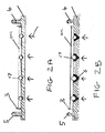
- a planar substrate according to the present invention comprises a sheet of transparent quartz 1 patterned with an 11x4 rectangular array of hemispherical wells 2 which function as droplet-receiving locations. The whole array is surrounded by a lip 3 to contain oil and rails 4 and 5 profiled to receive the wheels of the printer head.
- Figures 2a and 2b show two different cross-sections of a typical substrate. In Figure 2a the wells do not extend completely through 1 whilst in Figure 2b 1 is provided with perforations stopped up by wax 6 which is solid at room temperature but which melts away when the sheet is heated to in excess of 80°C.
- Each of 2 also includes a micro-heating element (not shown) to enable the temperature of the contents to be controlled. In use, the underside of 1 is illuminated in the direction shown by light from an LED (also not shown).
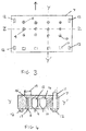
- Figure 3 shows a plan view of the underside of the printer head 7. it comprises a 3x4 array of nozzles corresponding to first, third and second nozzle types 8, 9, 10 arranged in transverse rows which when 7 is in use correspond to corresponding transverse rows of 2 on 1.
- a line of photodetectors 11 are made integral with 7 and likewise arranged in a corresponding transverse row on 7 spaced apart from the nozzles.
- the underside of 7 finally includes 4 grooved wheels 12 designed to be locatable on 4 and 5 and driven by an electric motor (not shown) in order to enable 7 to be stepped across 1 in the direction shown by the arrow.
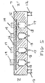
- FIGS 4 and 5 show sectional profiles of 7 along the planes defined respectively by the lines Y-Y' and Z-Z'. From these illustrations, it can be seen that each of the nozzle types 9 and 10 in the array are connected to corresponding reservoirs 13, 14 and that each reservoir of a given type is connected to other of the same type by microfluidic piping 15 and an inlet 16.16 may be connected to a pressure-driven pump or piezo actuator or made subject to an electric field which can be operated to cause droplets 17 to emerge from the various nozzles.
- Each first nozzle type is separately connected by its own microfluidic pipe 18 to a nucleotide generating site 19 in which a stream of nucleotide triphosphates in aqueous medium are generated from a DNA sample by progressive pyrophosphorolysis by a polymerase.
- the aqueous medium is then introduced into 18 by positive pressure, thereby causing droplets to emerge from 8 for printing into 2.
- the droplets are caused to emerge from 8 at a rate such that very few droplets contain more than one nucleotide triphosphate. In practice this may mean that droplets may emerge which contain no nucleotide triphosphates.
- the droplets are caused to emerge from 8, 9 and 10 at a rate which are synchronised by a microprocessor (not shown) with the movement of 7 across the array of 2 on 1.
- nozzle type 9 dispenses aqueous droplet containing thermostable inorganic pyrophosphatase (TPP)
- TPP thermostable inorganic pyrophosphatase
- nozzle type 10 dispenses aqueous droplets containing a probe system of the type described below in the Example.
- fluorescence characteristic of the nucleotide triphosphate it originally contained is measured by each of 11 as it traverses 1. This in turn generates an electrical signal which is fed to a microprocessor or stand-alone computer (not shown) for analysis.
- a first, single-stranded oligonucleotide was prepared, having the following nucleotide sequence:
- a second, single-stranded oligonucleotide comprising (1) a second oligonucleotide region having a sequence complementary to the 3' end of the first oligonucleotide with a single base mismatch; (2) a third oligonucleotide region having a sequence complementary to the 5' end of the first oligonucleotide and (3) a 76 base pair single-stranded linker region, was also prepared. It had the following nucleotide sequence: wherein additionally P represents a 5' phosphate group.
- a microdroplet comprising the probe system was then prepared for use in nozzle type 10 of the apparatus exemplified above. It had a composition corresponding to that derived from the following formulation:
- This droplet was printed into a well on a quartz slide containing an aqueous medium including 2.8uL of dTTP, 10 nM. Capture of the dTTP and ligation of the second oligonucleotide to the first to form a closed-loop used probe was then carried out in the well by incubating the contents at 37°C for 50 minutes after which the temperature was increased to 70°C for a further 50 minutes. Growth in fluorescence of the relevant fluorophore dye was the then observed to occur in the well as the cycle of exonucleolysis and regeneration of the used probe occurred.
Landscapes
- Chemical & Material Sciences (AREA)
- Health & Medical Sciences (AREA)
- Life Sciences & Earth Sciences (AREA)
- General Health & Medical Sciences (AREA)
- Analytical Chemistry (AREA)
- Organic Chemistry (AREA)
- Proteomics, Peptides & Aminoacids (AREA)
- Physics & Mathematics (AREA)
- Biochemistry (AREA)
- Immunology (AREA)
- Zoology (AREA)
- Engineering & Computer Science (AREA)
- Pathology (AREA)
- Wood Science & Technology (AREA)
- General Physics & Mathematics (AREA)
- Chemical Kinetics & Catalysis (AREA)
- Clinical Laboratory Science (AREA)
- Bioinformatics & Cheminformatics (AREA)
- General Engineering & Computer Science (AREA)
- Biophysics (AREA)
- Genetics & Genomics (AREA)
- Biotechnology (AREA)
- Microbiology (AREA)
- Molecular Biology (AREA)
- Dispersion Chemistry (AREA)
- Hematology (AREA)
- Measuring Or Testing Involving Enzymes Or Micro-Organisms (AREA)
Abstract
An apparatus for sequencing a nucleic acid by printing droplets at least some of which contain single nucleotides derived from the nucleic acid is provided. It is characterised by comprising;
¢ a planar substrate having a face with droplet-receiving locations arranged in at least one track parallel to a first axis defining the substrate;
¢ a printer head comprising a plurality of droplet-dispensing nozzle types juxtaposed immediately above the droplet-receiving locations so that each nozzle type can in turn dispense a droplet into the droplet-receiving locations;
¢ a means for stepping the printer head along the first axis relative to the droplet-receiving locations;
¢ at least one source of incident electromagnetic radiation adapted to illuminate the droplet-receiving locations and
¢ at least one photodetector to detect adapted to detect fluorescence radiation emitted by each droplet-receiving location after illumination.
Description
- This invention relates to an improved droplet sequencing device and method in which single nucleotides are printed onto a substrate before being captured by an oligonucleotide probe system and identified using fluorescence spectroscopy.
- In our previously filed patent applications
WO2014053854 andWO2014167323 we have disclosed a method for sequencing nucleic acids such as synthetic and naturally occurring DNA and RNA by a method which involves first creating an ordered stream of single nucleotides from the corresponding precursor analyte for example by progressive pyrophosphorolysis or exonucleolysis. Thereafter, the single nucleotides are captured in aqueous microdroplets where they are treated with a quenched, fluorophore-labelled oligonucleotide probe system which, after capture occurs, undergoes progressive exonucleolysis to liberate single nucleotides bearing free fluorophores whose characteristic fluorescence emissions enable the nucleotide originally captured to be reliably identified. Examples of probes and methods suitable for this purpose have been described inWO2014053853 ,GB1402644.7 EP14170832.1 GB1412977.9 - Whilst the method described above can be carried out by creating and manipulating a stream of the droplets dispersed for example in an immiscible carrier medium such as silicone oil, we have recently found that the method can advantageously and more effectively performed by printing the droplets directly onto the surface of a substrate as they are formed. This method is the subject of our recently filed application
GB1310584.6 - a planar substrate having a face with droplet-receiving locations arranged in at least one track parallel to a first axis defining the substrate;
- a printer head comprising a plurality of droplet-dispensing nozzle types juxtaposed immediately above the droplet-receiving locations so that each nozzle type can in turn dispense a droplet into the droplet-receiving locations;
- a means for stepping the printer head along the first axis relative to the droplet-receiving locations;
- at least one source of incident electromagnetic radiation adapted to illuminate the droplet-receiving locations and
- at least one photodetector adapted to detect fluorescence radiation emitted by each droplet-receiving location after illumination.
- The planar substrate employed in the apparatus of the invention is suitably a sheet of resilient material which has a face with a plurality, suitably many tens, hundreds, thousands or millions, of droplet-receiving locations capable of holding droplets printed thereon in place. In one embodiment, these locations are virtual locations and are created as the printer head prints droplets. In another, they are patterned onto the face and for example comprise depressions in the face of the substrate (e.g. wells) or cups formed thereon. In another embodiment, the droplet-receiving locations are coated with a hydrophilic material to further enhance the adherence of the droplet to the substrate. In yet another embodiment the depressions or cups are hemi-spherical in morphology with a maximum cross-section in the micrometre range. Preferably the substrate is at least optically transparent at each droplet-receiving location although it is also contemplated that the whole substrate may comprise an optically transparent sheet such as quartz, glass or clear plastic.
- The droplet-receiving locations may if so desired be provided with one or more holes in the bottom to enable the contents thereof to be drained away after having been interrogated. If this embodiment is used, it is preferred to initially stop up each hole with a plug of high melting material; for example a wax which can be melted away when the time comes.
- In one embodiment, the droplet-receiving locations are arranged in the form of a linear track running parallel to a first axis of the face of the substrate along which the printer head is stepped. In a preferred embodiment, the substrate is provided with a plurality of such tracks running parallel to each other thereby creating a rectangular array. In another, the plurality of tracks may be grouped together to form higher order track-structures each of which corresponds to one traverse of the printer head across the face.
- In addition to the track(s) of droplet-receiving locations the substrate may possess one or more lips running around its extremities or areas therein to ensure that a preferred droplet-immiscible solvent coating it is held in place. In another embodiment, either side of the tracks runs a means to ensure that the printer head remains precisely located over the droplet-receiving locations as it moves over the substrate. In one arrangement, this means comprises a pair of profiled rails running parallel to the tracks which can cooperate with corresponding profiles on wheels, grooves or the like on the printer head. This, however, is only one example of many possible arrangements which will easily occur to the skilled man; for example the mirror-image arrangement where the rails are located on the printer heads and the wheels or grooves on the substrate will be immediately apparent and are included within the scope of the invention.
- Turning to the printer head this comprises a plurality of droplet-printing nozzle types which, when the printer head is in use, are juxtaposed immediately above the droplet-receiving locations so that each nozzle can in turn cause a droplet to be dispensed thereinto. Each nozzle type may consist of a single nozzle or a plurality of like nozzles. Dispensing can be caused to occur by any of the known means in the art including for example by electrical or electrostatic means. Since the dimensions of the droplets preferably have dimensions in the micrometre range it is preferred that the nozzles are similarly dimensioned. In one embodiment, the nozzles in a given type are connected to a reservoir or a microfluidic system for dispensing materials.
- In one preferred embodiment, each nozzle type comprises a plurality of nozzles and each nozzle in a given nozzle type is arranged in line along a second axis perpendicular to the first axis of the face of the substrate and wherein the distance between each adjacent nozzle in said line is the same or an integral multiple of the distance between adjacent droplet-receiving locations in adjacent tracks. In this embodiment, lines of nozzles representing a given nozzle type are arranged in parallel one behind the other to enable each droplet location in a track to be filled sequentially with liquid issuing from nozzles in each droplet type.
- In another preferred embodiment the printer head comprises at least first and second nozzle types wherein the first type dispenses aqueous droplets at least some of which contain a single nucleotide; suitably a nucleotide monophosphate, a nucleotide diphosphate or most preferably a nucleotide triphosphate and the second nozzle type dispenses one or more, preferably four different oligonucleotide probe systems having the characteristics described in one of
WO2014053853 ,WO2014167323 ,GB1402644.7 EP14170832.1 GB1412977.9 - Briefly, these probe system comprise one or more oligonucleotide components at least one of which includes one or more fluorophores which in the probe systems' unused state are essentially quenched and non-fluorescing. Once the probes have captured the single nucleotide they are selective for, they become susceptible to progressive exonucleolytic degradation thereby releasing fluorophore-labelled nucleotides which are unquenched.
- Typically the second nozzle type will dispense aqueous droplets comprising the probe systems and the various reagents required to cause the capture reaction and optionally the degradation to occur including a polymerase, a ligase and optionally the exonuclease. However it is contemplated that these components may be introduced separately into the droplet-receiving locations by means of one or more further nozzle types if so desired. Thus, in a preferred embodiment, the first and second nozzle types may be augmented by one or more third nozzle types which dispense droplets containing an enzyme. For example where the droplets dispensed by the first nozzle type contain single nucleotide triphosphates generated by progressive pyrophosphorolysis of a precursor DNA or RNA analyte the third nozzle type can be used to introduce droplets containing a pyrophosphatase into the droplet-receiving location in order to destroy any pyrophosphate present along with the nucleotide triphosphate before the probe system is introduced. In this particular instance, the third nozzle type is conveniently located between the first and second nozzle type on the printer head. However this embodiment is not to be construed as limiting and it may well be desirable to introduce other enzymes at other points in the printing process; e.g. the exonuclease referred to above.
- The nozzles associated with each nozzle type may be provided with heater or cooler elements to heat or cool any liquid before it issues forth from the nozzle. This is particularly useful to ensure that at any given point in the printing the contents of the droplet-receiving locations are at the optimum temperature.
- The printer head may also further comprise a dispenser for dispensing a water-immiscible coating onto the face of the substrate bearing the droplet-receiving locations prior to use. In one embodiment this liquid comprises oil, e.g. silicone oil, optionally containing one or more surfactants. In another embodiment this oil is a liquid at a relatively high temperature but can be frozen into a solid wax when printing is complete. This has the advantage of further confining the contents of the droplet receiving location in a solid matrix whilst for example analysis of the contents is taking place.
- The printer head may also contain at least one second dispenser for dispensing cleaning fluid onto the face of the substrate bearing the droplet-receiving locations. This enables the substrate to be cleaned between runs making it reusable.
- Suitably the means for stepping the printer head comprises a microprocessor-controlled motor for driving wheels located on the underside of the printer head and which engage with the tracks or more preferably a linear translation stage or stepper motor which moves it relative to the substrate (or vice versa).
- The source used to illuminate the droplet-receiving locations with electromagnetic radiation is suitably a plasma lamp, a halogen lamp or preferably a laser or an LED operating at a frequency which will stimulate the free fluorophores generated at the droplet-receiving location. In one embodiment, the printer head and this source are located on the same side of the substrate but in a more preferred embodiment they are located on opposite sides so that the incident radiation is transmitted through the optically-transparent substrate. Likewise the photodetector can be located on the same or opposite sides of the substrate as the source but preferably it is located on the opposite side. In such a case the photodetector may be made integral with the printer head so that it moves therewith as the face is traversed. The photodetector used can be any type which is able to detect radiation frequency(s) characteristic of the different fluorophores used.
- In addition to the above-mentioned components, the apparatus may include other items such as ancillary optics (e.g. mirrors, waveguides, filters and lenses to manipulate and focus beams of the incident and fluorescence radiation), microfluidic piping, and one or more microprocessors for controlling some or all of the following functions; addition and timing of the droplets into the droplet-receiving locations, timing of the illumination and interrogation of the droplet-receiving locations and analysis of any signal produced by the photodetector. Such analysis may however be conducted on a stand-alone computer if so desired.
- In a second aspect of the invention there is provided a method suitable for use with the apparatus. It comprises a method of sequencing a nucleic acid characterised by comprising the steps of (1) delivering an aqueous medium containing an ordered stream of single nucleotides derived from the nucleic acid to a first droplet nozzle type of a printer head; (2) printing a first droplet, containing a single nucleotide, from the first droplet nozzle type into at least one droplet-receiving location on a planar substrate; (3) thereafter printing into the same droplet-receiving locations a second aqueous droplet containing at least one probe system comprising an oligonucleotide labelled with fluorophores wherein the fluorophores are only detectable after release by exonucleolysis; a polymerase and a ligase; (4) allowing the fluorophores to be released at the droplet-receiving location(s); (5) illuminating the droplet-receiving location(s) with incident electromagnetic radiation and detecting fluorescence radiation characteristic of the single nucleotide emitted therefrom.
- In one embodiment of this method the nucleic acid is a synthetic or naturally-occurring DNA or RNA or fragment thereof; in another the single nucleotides are nucleotide triphosphates which have been generated by progressive pyrophosphorolysis of the nucleic acid. In the case of this latter embodiment, the method preferably further comprises between steps (2) and step (3) the additional step of printing a third aqueous stream containing a pyrophosphatase into the droplet-receiving location to consume residual pyrophosphate. In yet another embodiment of the method generally either the second droplet further contains an exonuclease or alternatively a fourth aqueous droplet containing an exonuclease is printed into the droplet-receiving location between steps (3) and (4).
- In all the embodiments of the method described above the probe systems employed may be selected from any of those described in in
WO2014053853 ,WO2014167323 ,GB1402644.7 EP14170832.1 GB1412977.9 - As regards the second oligonucleotide in the pair, this is single-stranded and suitably has a nucleotide base sequence which is wholly or partially the compliment of that of the single-stranded region of the first oligonucleotide starting one nucleotide base beyond the end of the double-stranded region. The length of the second oligonucleotide is not critical and can be longer or shorter than the single-stranded region to which it can bind although it is preferably not n-1 nucleotide bases long. More preferably, the length of the second oligonucleotide is chosen so that in the captured molecule a short overhang of unpaired nucleotide bases (e.g. 2 to 10 nucleotide bases) remains on one or other of the two strands thereof. Preferably, in this class the fluorophores are located on the second oligonucleotide. Probe systems of this class work by attaching the single nucleotide base to the double-stranded end of the first oligonucleotide and hybridising the second oligonucleotide onto the remaining single-stranded region to generate a captured molecule which is double-stranded apart from its overhang.
- In a second preferred aspect, the probe system comprises a class of single oligonucleotides each consisting of a single-stranded nucleotide region the ends of which are attached to two different double-stranded regions. Here, the single-stranded nucleotide region is comprised of one nucleotide base only making the probe extremely selective for the detection of the target i.e. the complimentary single nucleotide base in the droplet.
- Turning to the double-stranded oligonucleotide region(s), it is preferred that they are derived or derivable from two oligonucleotide precursors, each preferably closed looped, or from a common single-stranded oligonucleotide precursor by folding the latter's ends back on themselves to create two closed-loop oligonucleotide base regions with an intermediate gap constituting the single-stranded nucleotide region. In all cases the effect is the same; adjacent to the ends of the single-stranded nucleotide region will be 3' and 5' free ends on the other strand of the oligonucleotide region to which the corresponding 5' and 3' ends of the target can be attached. Thus use of the probe system involves a process of attaching the single-stranded nucleotide region to the target single nucleotide base by joining up the available 3' and 5' ends of the probe system to generate a used probe system which is double-stranded along its whole length.
- Suitably, the double-stranded oligonucleotide region(s) are up to 50 nucleotide base pairs long, preferably up to 45 nucleotide base pairs, more preferably in the
range 5 to 40 nucleotide base pairs and most preferably in therange 10 to 30. Longer regions may be used but the potential risk that access to the single-stranded nucleotide region by the target may become restricted through entanglement. This makes this embodiment potentially less attractive. - In this embodiment it is preferred that the fluorophores bound to the double-stranded oligonucleotide region(s) are located remote from the single-stranded nucleotide region. Finally in one embodiment it is preferred that at least one of the double-stranded oligonucleotide regions comprises at least one restriction enzyme recognition site preferably adjacent the region where the fluorophores are located or clustered. For these probe systems, liberation of the fluorophores comes about by first a restriction enzyme exhibiting endonucleolytic behaviour and making a double-stranded cut in the used probe system at the site mentioned above. The short fragments so created may then be degraded further by the exonuclease into single nucleotides at least some of which will be labelled with fluorophores. Thus, when the used probe system comprises multiple fluorophores this leads to the release of a cascade of fluorophores which, by virtue of them now being separated from each other and/ or their associated quenchers, are now free to fluoresce in the normal way. Such a restriction enzyme recognition site will typically comprise a specific sequence of from 2 to 8 nucleotide pairs. In another preferred embodiment the restriction enzyme recognition site will be one created by binding of the single nucleotide to the single-stranded nucleotide region.
- In a third preferred aspect the probe system is comprised of three components; (a) a first single-stranded oligonucleotide labelled with fluorophores in an undetectable state and (b) second and third unlabelled single-stranded oligonucleotides capable of hybridising to complementary regions on the first oligonucleotide. In one embodiment the second and third oligonucleotides are discrete entities whilst in another they are linked to each other by means of a linker region. In this latter case, in one embodiment the linker region links ends of the second and third oligonucleotides; preferably the 5' end of the second and the 3' end of the third oligonucleotide. The linker region can in principle be any divalent group but is conveniently another single- or double-stranded oligonucleotide fragment. In one embodiment the linker region is unable to hybridise substantially to the first oligonucleotide.
- The first, second and third oligonucleotides are chosen so that the second and third oligonucleotides can hybridise respectively to 3' side and 5' side flanking regions on the first oligonucleotide which themselves are juxtaposed either side of a capture region which comprises the single nucleotide whose nucleotide base is complementary to the one borne by the nucleotide triphosphate to be detected. This makes the three-component probe system highly selective for that particular nucleotide triphosphate. Thus, for example, if the analyte is derived from DNA and the first, second and third oligonucleotides are deoxyribonucleotides, the capture region will be highly selective for deoxyadenosine triphosphate if the nucleotide it comprises bears a thymine base.
- Typically, the first oligonucleotide is up to 150 nucleotides long, preferably between 20 and 100 nucleotides. In one embodiment the second oligonucleotide is longer than the complementary 3' side flanking region of the first oligonucleotide by up to 10 preferably from 1 to 5 nucleotides. In another, there is a single nucleotide mismatch between the 3' end of the first oligonucleotide and the nucleotide opposite it on the second oligonucleotide to prevent the nucleotide triphosphate being captured by the polymerase at this point. In yet another embodiment the 3' end of the third oligonucleotide includes an element resistant to exonucleolytic degradation to ensure that the fourth oligonucleotide produced in step (3) is not itself subsequently digested. This can be achieved for example by way of incorporating one or more phosphorothioate linkages, a G-Quadruplex, a boronated nucleotide, an inverted dT or ddT, a C3 spacer or a phosphate group at or near that particular end.
- Use of the this third class of probe system generates a double-stranded used probe whose constituent strands are respectively the first oligonucleotide and a complementary fourth oligonucleotide which when read in its 5'-3' direction is comprised of the second oligonucleotide, then a nucleotide derived from the single nucleotide triphosphate and finally the third oligonucleotide. If the second and third oligonucleotides have previously been joined together by a linker region then it will be readily apparent that the fourth oligonucleotide will comprise a closed loop strand that is highly resistant to exonucleolysis. This closed loop can then be used to bind to a further first oligonucleotide enabling further fluorophores to be liberated; thereby creating a cyclic process which grows the fluorescence signal intensity.
- In all three aspects of the probe system at least one of the oligonucleotide components in the probe system is multiply labelled with its own unique type of fluorophores and these fluorophores are substantially undetectable when the probe system is in an unused state. Thus, although a fluorophore may exhibit general, low-level background fluorescence across a wide part of the electromagnetic spectrum, there will typically be one or a small number of specific wavelengths or wavelength envelopes where the intensity of the fluorescence is at a maximum. It is at one or more of these maxima where the fluorophore is characteristically detected that essentially no fluorescence should occur. In the context of this patent, by the term 'essentially non-fluorescing' or equivalent wording is meant that the intensity of fluorescence of the total number of fluorophores attached to the probe system at the relevant characteristic wavelength or wavelength envelope is less than 25%; preferably less than 10%; more preferably less than 1% and most preferably less than 0.1% of the corresponding intensity of fluorescence of an equivalent number of free fluorophores.
- In principle, any method can be used to ensure that in the probe systems' unused state the fluorophores are essentially non-fluorescing. One approach is to additionally attach quenchers in close proximity to them. Another is based on the observation that when multiple fluorophores are attached in close proximity to each other they tend to quench each other sufficiently well that the criterion described In the previous paragraph can be achieved without the need for quenchers. In this context of this patent, what constitutes 'close proximity' between fluorophores or between fluorophores and quenchers will depend on the particular fluorophores and quenchers used and possibly the structural characteristics of the oligonucleotide to which it is bound. Consequently, it is intended that this term should be construed with reference to the required outcome rather than any particular structural arrangement of the various elements. However, and for the purposes of providing exemplification only, it is pointed out that when adjacent fluorophores or adjacent fluorophores and quenchers are separated by a distance corresponding to the characteristic Förster distance (typically less than 5nm) sufficient quenching will generally be achieved.
- Suitably the relevant component of the probe systems mentioned above is labelled with at least 1, preferably up to 20 fluorophores. To obtain maximum advantage, it is preferred that this component is labelled with at least 2 preferably at least 3 fluorophores. Consequently, ranges constructed from any permutation of these maxima and minima are specifically envisaged herein. If quenchers are employed, it is likewise preferred that this component is labelled with up to 20, preferably up to 10 and most preferably up to 5 of the same.
- As regards the fluorophores themselves, they can in principle be chosen from any of those conventionally used in the art including but not limited to xanthene moieties e.g. fluorescein, rhodamine and their derivatives such as fluorescein isothiocyanate, rhodamine B and the like; coumarin moieties (e.g. hydroxy-, methyl- and aminocoumarin) and cyanine moieties such as Cγ2, Cy3, Cy5 and Cy7. Specific examples include fluorophores derived from the following commonly used dyes: Alexa dyes, cyanine dyes, Atto Tec dyes, and rhodamine dyes. Examples also include: Atto 633 (ATTO-TEC GmbH), Texas Red, Atto 740 (ATTO-TEC GmbH), Rose Bengal, Alexa Fluor™ 750 Cs-maleimide (Invitrogen), Alexa Fluor™ 532 C2-maleimide (Invitrogen) and Rhodamine Red C2-maleimide and Rhodamine Green as well as phosphoramadite dyes such as Quasar 570. Alternatively, a quantum dot or a near infra-red dye such as those supplied by LI-COR Biosciences can be employed. The fluorophore is typically attached to the relevant oligonucleotide component via a nucleotide base using chemical methods known in the art.
- Suitable quenchers include those which work by a Förster resonance energy transfer (FRET) mechanism. Examples of commercially available quenchers which can be used in association with the above mentioned-fluorophores include but are not limited to DDQ-1, Dabcyl, Eclipse, lowa Black FQ and RQ, IR Dye-QC1, BHQ-0, BHQ-1, -2 and -3 and QSY-7 and -21.
- As mentioned above the capture of the single nucleotide triphosphate by the probe systems described above is suitably carried out at the droplet-receiving location in the presence of a ligase and a polymerase in at a temperature in the range 20 to 80°C with the exonucleolysis reaction occurring in the range 30 to 100°C.
- The apparatus of the present invention, which is especially suitable for sequencing long-chain DNA or RNA derived from naturally-occurring sources, is now illustrated by the following example in which:
-
Figure 1 shows a plan view of a substrate used in the apparatus; -
Figures 2a and 2b show transverse sections of the substrate along the line X-X; -
Figure 3 shows an underside view of the printer head; -
Figure 4 shows a longitudinal section of the printer head in use along the line Y-Y and -
Figure 5 shows a transverse section of the printer head along the line Z-Z. - With reference to
Figure 1 a planar substrate according to the present invention comprises a sheet oftransparent quartz 1 patterned with an 11x4 rectangular array ofhemispherical wells 2 which function as droplet-receiving locations. The whole array is surrounded by alip 3 to contain oil and rails 4 and 5 profiled to receive the wheels of the printer head.Figures 2a and 2b show two different cross-sections of a typical substrate. InFigure 2a the wells do not extend completely through 1 whilst inFigure 2b 1 is provided with perforations stopped up by wax 6 which is solid at room temperature but which melts away when the sheet is heated to in excess of 80°C. Each of 2 also includes a micro-heating element (not shown) to enable the temperature of the contents to be controlled. In use, the underside of 1 is illuminated in the direction shown by light from an LED (also not shown). -
Figure 3 shows a plan view of the underside of theprinter head 7. it comprises a 3x4 array of nozzles corresponding to first, third andsecond nozzle types wheels 12 designed to be locatable on 4 and 5 and driven by an electric motor (not shown) in order to enable 7 to be stepped across 1 in the direction shown by the arrow. -
Figures 4 and5 show sectional profiles of 7 along the planes defined respectively by the lines Y-Y' and Z-Z'. From these illustrations, it can be seen that each of thenozzle types reservoirs microfluidic piping 15 and an inlet 16.16 may be connected to a pressure-driven pump or piezo actuator or made subject to an electric field which can be operated to causedroplets 17 to emerge from the various nozzles. Each first nozzle type is separately connected by its ownmicrofluidic pipe 18 to anucleotide generating site 19 in which a stream of nucleotide triphosphates in aqueous medium are generated from a DNA sample by progressive pyrophosphorolysis by a polymerase. The aqueous medium is then introduced into 18 by positive pressure, thereby causing droplets to emerge from 8 for printing into 2. The droplets are caused to emerge from 8 at a rate such that very few droplets contain more than one nucleotide triphosphate. In practice this may mean that droplets may emerge which contain no nucleotide triphosphates. Generally, the droplets are caused to emerge from 8, 9 and 10 at a rate which are synchronised by a microprocessor (not shown) with the movement of 7 across the array of 2 on 1. In the embodiment shownnozzle type 9 dispenses aqueous droplet containing thermostable inorganic pyrophosphatase (TPP) whilstnozzle type 10 dispenses aqueous droplets containing a probe system of the type described below in the Example. In use, once each 2 is filled by droplets from 8, 9 and 10 and incubation has occurred, fluorescence characteristic of the nucleotide triphosphate it originally contained is measured by each of 11 as it traverses 1. This in turn generates an electrical signal which is fed to a microprocessor or stand-alone computer (not shown) for analysis. - A first, single-stranded oligonucleotide was prepared, having the following nucleotide sequence:
- 5'TCGTGCCTCATCGAACATGACGAGGXXQXXGGTTTGTGGT3'
- A second, single-stranded oligonucleotide comprising (1) a second oligonucleotide region having a sequence complementary to the 3' end of the first oligonucleotide with a single base mismatch; (2) a third oligonucleotide region having a sequence complementary to the 5' end of the first oligonucleotide and (3) a 76 base pair single-stranded linker region, was also prepared. It had the following nucleotide sequence:wherein additionally P represents a 5' phosphate group.

- A microdroplet comprising the probe system was then prepared for use in
nozzle type 10 of the apparatus exemplified above. It had a composition corresponding to that derived from the following formulation: - 56uL 5x buffer pH 7.5
- 28uL comprising 4 different first oligonucleotides (A,G, C and T selective), 100 nM 28uL second oligonucleotide, 10 nM
- 0.4U Phusion II Hot Start polymerase (exonuclease)
- 1.6U Bst Large Fragment polymerase
- 20U E. coli ligase
- Water to 280uL
- 200uLTrizma hydrochloride, 1M, pH 7.5
- 13.75uL aqueous MgCl2, 1M
- 2.5uL Dithiothreitol, 1M
- 50uL Triton X-100 surfactant (10%)
- 20uL Nicotinamide adenine dinucleotide, 100 uM
- 166.67uL KCl
- Waterto 1mL
- This droplet was printed into a well on a quartz slide containing an aqueous medium including 2.8uL of dTTP, 10 nM. Capture of the dTTP and ligation of the second oligonucleotide to the first to form a closed-loop used probe was then carried out in the well by incubating the contents at 37°C for 50 minutes after which the temperature was increased to 70°C for a further 50 minutes. Growth in fluorescence of the relevant fluorophore dye was the then observed to occur in the well as the cycle of exonucleolysis and regeneration of the used probe occurred.


Claims (18)
- An apparatus for sequencing a nucleic acid by printing droplets at least some of which contain single nucleotides derived from the nucleic acid characterised by comprising;• a planar substrate having a face with droplet-receiving locations arranged in at least one track parallel to a first axis defining the substrate;• a printer head comprising a plurality of droplet-dispensing nozzle types juxtaposed immediately above the droplet-receiving locations so that each nozzle type can in turn dispense a droplet into the droplet-receiving locations;• a means for stepping the printer head along the first axis relative to the droplet-receiving locations;• at least one source of incident electromagnetic radiation adapted to illuminate the droplet-receiving locations and• at least one photodetector adapted to detect fluorescence radiation emitted by each droplet-receiving location after illumination.
- An apparatus as claimed in claim 1 characterised in that the droplet-dispensing nozzle types are arranged in line one behind the other.
- An apparatus as claimed in claim 1 or claim 2 characterised in that the substrate comprises an array of droplet-receiving locations arranged as a plurality of tracks parallel to the first axis.
- An apparatus as claimed in claim 3 characterised in that the plurality of droplet-dispensing nozzle types each comprise a plurality of nozzles and wherein the nozzles in a given droplet-dispensing nozzle type are arranged in line along a second axis perpendicular to the first and wherein the distance between each adjacent nozzle in said line is the same or an integral multiple of the distance between adjacent droplet-receiving locations in adjacent tracks.
- An apparatus as claimed in any of the preceding claims characterised by further comprising at least one dispenser for dispensing a droplet-immiscible coating onto the surface of the substrate.
- An apparatus as claimed in any of the preceding claims characterised by further comprising a suction nozzle for removing the droplets and/or the coating from the substrate after the fluorescence radiation has been detected.
- An apparatus as claimed in any of the preceding claims characterised by further comprising at least one second dispenser for dispensing cleaning fluid onto the substrate.
- An apparatus as claimed in any of the preceding claims characterised in that each droplet-receiving location includes a heater or at least some of the locations share a common heater.
- An apparatus as claimed in any of the preceding claims characterised in that the substrate and printer head are provided with a wheel or groove and rail arrangement to enable them to prevent lateral movement of one relative to the other.
- An apparatus as claimed in any of the preceding claims characterised in that either (1) the printer head location is fixed and the substrate is moveable along the first axis relative thereto or (2) the substrate location is fixed and the printer head is moveable along the first axis relative thereto.
- An apparatus as claimed in any of the preceding claims characterised in that the substrate at each droplet-receiving location is optically transparent and that each droplet-receiving location is illuminated by the source of incident radiation on the side of the substrate opposite that which is adjacent to the photodetector.
- An apparatus as claimed in any of claims 1 to 10 characterised in that the photodetector and source of incident radiation are located on the same side of the substrate.
- An apparatus as claimed in any of the preceding claims characterised in that the droplet-dispensing nozzle types are comprised of at least of first and second types wherein the first type is adapted to dispense droplets containing single nucleotides and the second type is adapted to dispense oligonucleotide probe systems capable of capturing the single nucleotide and undergoing fluorescence when digested by exonucleolysis.
- An apparatus as claimed in claim 13 characterised by comprising at least one third droplet-dispensing nozzle type adapted to dispense droplets containing an enzyme.
- A method of sequencing a nucleic acid characterised by comprising the steps of (1) delivering an aqueous medium containing an ordered stream of single nucleotides derived from the nucleic acid to a first droplet nozzle type of a printer head; (2) printing a first droplet, containing a single nucleotide, from the first droplet nozzle type into at least one droplet-receiving location on a planar substrate; (3) thereafter printing into the same droplet receiving location(s) a second aqueous droplet containing at least one probe system comprising an oligonucleotide labelled with fluorophores wherein the fluorophores are only detectable after release by exonucleolysis; a polymerase and a ligase; (4) allowing the fluorophores to be released at the droplet-receiving location(s); (5) illuminating the droplet-receiving location(s) with incident electromagnetic radiation and detecting fluorescence radiation characteristic of the single nucleotide emitted therefrom.
- A method as claimed in claim 15 characterised in that the single nucleotides are nucleotide triphosphates generated by progressive pyrophosphorolysis of the nucleic acid.
- A method as claimed in claim 16 characterised in that method further comprises between steps (2) and step (3) the additional step of printing a third aqueous stream containing a pyrophosphatase into the droplet-receiving location.
- A method as claimed in any of claims 15 to 17 characterised in that either the second droplet contains an exonuclease or a fourth aqueous droplet containing an exonuclease is printed into the droplet-receiving location between steps (3) and (4).
Priority Applications (5)
| Application Number | Priority Date | Filing Date | Title |
|---|---|---|---|
| EP15002007.1A EP3115109A1 (en) | 2015-07-06 | 2015-07-06 | Droplet sequencing device |
| PCT/EP2016/065968 WO2017005789A1 (en) | 2015-07-06 | 2016-07-06 | Droplet sequencing device |
| US15/741,344 US10525459B2 (en) | 2015-07-06 | 2016-07-06 | Droplet sequencing device |
| EP16738383.5A EP3319729B1 (en) | 2015-07-06 | 2016-07-06 | Droplet sequencing device |
| CN201680039664.6A CN107921433A (en) | 2015-07-06 | 2016-07-06 | Droplet sequencing device |
Applications Claiming Priority (1)
| Application Number | Priority Date | Filing Date | Title |
|---|---|---|---|
| EP15002007.1A EP3115109A1 (en) | 2015-07-06 | 2015-07-06 | Droplet sequencing device |
Publications (1)
| Publication Number | Publication Date |
|---|---|
| EP3115109A1 true EP3115109A1 (en) | 2017-01-11 |
Family
ID=53776271
Family Applications (2)
| Application Number | Title | Priority Date | Filing Date |
|---|---|---|---|
| EP15002007.1A Ceased EP3115109A1 (en) | 2015-07-06 | 2015-07-06 | Droplet sequencing device |
| EP16738383.5A Active EP3319729B1 (en) | 2015-07-06 | 2016-07-06 | Droplet sequencing device |
Family Applications After (1)
| Application Number | Title | Priority Date | Filing Date |
|---|---|---|---|
| EP16738383.5A Active EP3319729B1 (en) | 2015-07-06 | 2016-07-06 | Droplet sequencing device |
Country Status (4)
| Country | Link |
|---|---|
| US (1) | US10525459B2 (en) |
| EP (2) | EP3115109A1 (en) |
| CN (1) | CN107921433A (en) |
| WO (1) | WO2017005789A1 (en) |
Families Citing this family (3)
| Publication number | Priority date | Publication date | Assignee | Title |
|---|---|---|---|---|
| CN110621786A (en) | 2017-05-15 | 2019-12-27 | 贝斯4创新公司 | Mononucleotide detecting method and relevant probe |
| EP3527673A1 (en) * | 2018-02-15 | 2019-08-21 | QIAGEN GmbH | Sequencing method |
| US11590488B2 (en) * | 2019-03-06 | 2023-02-28 | Festo Se & Co. Kg | Dosing device |
Citations (8)
| Publication number | Priority date | Publication date | Assignee | Title |
|---|---|---|---|---|
| US5879944A (en) * | 1995-09-04 | 1999-03-09 | Fuji Photo Film Co., Ltd. | Liquid spotting method and liquid spotting device |
| US20020074342A1 (en) * | 2000-11-14 | 2002-06-20 | Shafer David A. | Expression miniarrays and uses thereof |
| US20040021068A1 (en) * | 2001-12-19 | 2004-02-05 | Staats Sau Lan Tang | Interface members and holders for microfluidic array devices |
| US20070015289A1 (en) * | 2003-09-19 | 2007-01-18 | Kao H P | Dispenser array spotting |
| WO2014053853A1 (en) | 2012-10-04 | 2014-04-10 | Base4 Innovation Ltd | Biological probes and the use thereof |
| WO2014053854A1 (en) | 2012-10-04 | 2014-04-10 | Base4 Innovation Ltd | Sequencing method |
| WO2014167323A1 (en) | 2013-04-09 | 2014-10-16 | Base4 Innovation Ltd | Single nucleotide detection method |
| WO2014199113A1 (en) * | 2013-06-13 | 2014-12-18 | Base4 Innovation Ltd | Droplet storage method |
Family Cites Families (10)
| Publication number | Priority date | Publication date | Assignee | Title |
|---|---|---|---|---|
| US6569620B1 (en) * | 1990-06-11 | 2003-05-27 | Somalogic, Inc. | Method for the automated generation of nucleic acid ligands |
| US6203759B1 (en) * | 1996-05-31 | 2001-03-20 | Packard Instrument Company | Microvolume liquid handling system |
| US6664044B1 (en) * | 1997-06-19 | 2003-12-16 | Toyota Jidosha Kabushiki Kaisha | Method for conducting PCR protected from evaporation |
| ITMI981564A1 (en) * | 1998-07-09 | 2000-01-09 | St Microelectronics Srl | NON-VOLATILE MEMORY ABLE TO RUN A PROGRAM INDEPENDENTLY |
| US20040203173A1 (en) * | 2003-04-08 | 2004-10-14 | Peck Bill J. | Apparatus and methods for droplet dispensing |
| EP2263802A1 (en) * | 2009-05-25 | 2010-12-22 | F. Hoffmann-La Roche AG | System and method for dispensing fluids |
| GB201402644D0 (en) | 2014-02-14 | 2014-04-02 | Base4 Innovation Ltd | Methylation detection method |
| US10227638B2 (en) | 2014-06-02 | 2019-03-12 | Base4 Innovation Ltd. | Nucleotide polymorphism detection method |
| GB201412977D0 (en) | 2014-07-22 | 2014-09-03 | Base4 Innovation Ltd | Single nucleotide detection method |
| GB201501012D0 (en) * | 2015-01-21 | 2015-03-04 | Base4 Innovation Ltd | Improved droplet sequencing apparatus and method |
-
2015
- 2015-07-06 EP EP15002007.1A patent/EP3115109A1/en not_active Ceased
-
2016
- 2016-07-06 US US15/741,344 patent/US10525459B2/en not_active Expired - Fee Related
- 2016-07-06 CN CN201680039664.6A patent/CN107921433A/en active Pending
- 2016-07-06 WO PCT/EP2016/065968 patent/WO2017005789A1/en active Application Filing
- 2016-07-06 EP EP16738383.5A patent/EP3319729B1/en active Active
Patent Citations (8)
| Publication number | Priority date | Publication date | Assignee | Title |
|---|---|---|---|---|
| US5879944A (en) * | 1995-09-04 | 1999-03-09 | Fuji Photo Film Co., Ltd. | Liquid spotting method and liquid spotting device |
| US20020074342A1 (en) * | 2000-11-14 | 2002-06-20 | Shafer David A. | Expression miniarrays and uses thereof |
| US20040021068A1 (en) * | 2001-12-19 | 2004-02-05 | Staats Sau Lan Tang | Interface members and holders for microfluidic array devices |
| US20070015289A1 (en) * | 2003-09-19 | 2007-01-18 | Kao H P | Dispenser array spotting |
| WO2014053853A1 (en) | 2012-10-04 | 2014-04-10 | Base4 Innovation Ltd | Biological probes and the use thereof |
| WO2014053854A1 (en) | 2012-10-04 | 2014-04-10 | Base4 Innovation Ltd | Sequencing method |
| WO2014167323A1 (en) | 2013-04-09 | 2014-10-16 | Base4 Innovation Ltd | Single nucleotide detection method |
| WO2014199113A1 (en) * | 2013-06-13 | 2014-12-18 | Base4 Innovation Ltd | Droplet storage method |
Also Published As
| Publication number | Publication date |
|---|---|
| WO2017005789A1 (en) | 2017-01-12 |
| EP3319729B1 (en) | 2020-03-18 |
| EP3319729A1 (en) | 2018-05-16 |
| CN107921433A (en) | 2018-04-17 |
| US10525459B2 (en) | 2020-01-07 |
| US20180353949A1 (en) | 2018-12-13 |
Similar Documents
| Publication | Publication Date | Title |
|---|---|---|
| US10690689B2 (en) | Microfluidic device for characterzing polynucleotides | |
| CA2951212C (en) | Single nucleotide detection method | |
| US9771615B2 (en) | Sequencing method | |
| EP3319729B1 (en) | Droplet sequencing device | |
| EP3625366A1 (en) | Single nucleotide detection method and associated probes | |
| US20180008985A1 (en) | Improved droplet sequencing apparatus and method | |
| US10000802B2 (en) | Sequencing method | |
| EP3510168B1 (en) | Single nucleotide detection method and associated probes | |
| EP3507381B1 (en) | Single nucleotide detection method and associated probes | |
| US20190203273A1 (en) | Single nucleotide detection method and associated probes |
Legal Events
| Date | Code | Title | Description |
|---|---|---|---|
| PUAI | Public reference made under article 153(3) epc to a published international application that has entered the european phase |
Free format text: ORIGINAL CODE: 0009012 |
|
| AK | Designated contracting states |
Kind code of ref document: A1 Designated state(s): AL AT BE BG CH CY CZ DE DK EE ES FI FR GB GR HR HU IE IS IT LI LT LU LV MC MK MT NL NO PL PT RO RS SE SI SK SM TR |
|
| AX | Request for extension of the european patent |
Extension state: BA ME |
|
| 18R | Application refused |
Effective date: 20170128 |
|
| STAA | Information on the status of an ep patent application or granted ep patent |
Free format text: STATUS: THE APPLICATION HAS BEEN REFUSED |