EP3114555B1 - System and method for gesture control - Google Patents
System and method for gesture control Download PDFInfo
- Publication number
- EP3114555B1 EP3114555B1 EP15710352.4A EP15710352A EP3114555B1 EP 3114555 B1 EP3114555 B1 EP 3114555B1 EP 15710352 A EP15710352 A EP 15710352A EP 3114555 B1 EP3114555 B1 EP 3114555B1
- Authority
- EP
- European Patent Office
- Prior art keywords
- input device
- input
- touch
- sensing electrodes
- electrodes
- Prior art date
- Legal status (The legal status is an assumption and is not a legal conclusion. Google has not performed a legal analysis and makes no representation as to the accuracy of the status listed.)
- Active
Links
- 238000000034 method Methods 0.000 title claims description 36
- 238000001514 detection method Methods 0.000 claims description 27
- 230000009471 action Effects 0.000 claims description 26
- 238000012545 processing Methods 0.000 claims description 26
- 230000005684 electric field Effects 0.000 claims description 9
- 230000005540 biological transmission Effects 0.000 claims description 7
- 239000000758 substrate Substances 0.000 claims description 5
- 239000010410 layer Substances 0.000 description 13
- 238000005259 measurement Methods 0.000 description 11
- 238000013459 approach Methods 0.000 description 7
- 238000013461 design Methods 0.000 description 4
- 239000011159 matrix material Substances 0.000 description 4
- 230000003287 optical effect Effects 0.000 description 4
- RYGMFSIKBFXOCR-UHFFFAOYSA-N Copper Chemical compound [Cu] RYGMFSIKBFXOCR-UHFFFAOYSA-N 0.000 description 3
- 229910052802 copper Inorganic materials 0.000 description 3
- 239000010949 copper Substances 0.000 description 3
- 230000010354 integration Effects 0.000 description 3
- 238000002604 ultrasonography Methods 0.000 description 3
- 101000985487 Homo sapiens Homologous recombination OB-fold protein Proteins 0.000 description 2
- 102100028711 Homologous recombination OB-fold protein Human genes 0.000 description 2
- 230000009286 beneficial effect Effects 0.000 description 2
- 238000010586 diagram Methods 0.000 description 2
- 238000005516 engineering process Methods 0.000 description 2
- 230000003993 interaction Effects 0.000 description 2
- 238000010079 rubber tapping Methods 0.000 description 2
- 230000004075 alteration Effects 0.000 description 1
- 238000013528 artificial neural network Methods 0.000 description 1
- 230000015572 biosynthetic process Effects 0.000 description 1
- 230000008859 change Effects 0.000 description 1
- 230000001419 dependent effect Effects 0.000 description 1
- 230000002708 enhancing effect Effects 0.000 description 1
- 238000011156 evaluation Methods 0.000 description 1
- 230000000977 initiatory effect Effects 0.000 description 1
- 238000011017 operating method Methods 0.000 description 1
- 230000035945 sensitivity Effects 0.000 description 1
- 239000002356 single layer Substances 0.000 description 1
- 230000003068 static effect Effects 0.000 description 1
- 238000006467 substitution reaction Methods 0.000 description 1
Images


Classifications
-
- G—PHYSICS
- G06—COMPUTING; CALCULATING OR COUNTING
- G06F—ELECTRIC DIGITAL DATA PROCESSING
- G06F3/00—Input arrangements for transferring data to be processed into a form capable of being handled by the computer; Output arrangements for transferring data from processing unit to output unit, e.g. interface arrangements
- G06F3/01—Input arrangements or combined input and output arrangements for interaction between user and computer
- G06F3/048—Interaction techniques based on graphical user interfaces [GUI]
- G06F3/0487—Interaction techniques based on graphical user interfaces [GUI] using specific features provided by the input device, e.g. functions controlled by the rotation of a mouse with dual sensing arrangements, or of the nature of the input device, e.g. tap gestures based on pressure sensed by a digitiser
- G06F3/0488—Interaction techniques based on graphical user interfaces [GUI] using specific features provided by the input device, e.g. functions controlled by the rotation of a mouse with dual sensing arrangements, or of the nature of the input device, e.g. tap gestures based on pressure sensed by a digitiser using a touch-screen or digitiser, e.g. input of commands through traced gestures
-
- G—PHYSICS
- G06—COMPUTING; CALCULATING OR COUNTING
- G06F—ELECTRIC DIGITAL DATA PROCESSING
- G06F3/00—Input arrangements for transferring data to be processed into a form capable of being handled by the computer; Output arrangements for transferring data from processing unit to output unit, e.g. interface arrangements
- G06F3/01—Input arrangements or combined input and output arrangements for interaction between user and computer
- G06F3/011—Arrangements for interaction with the human body, e.g. for user immersion in virtual reality
-
- G—PHYSICS
- G06—COMPUTING; CALCULATING OR COUNTING
- G06F—ELECTRIC DIGITAL DATA PROCESSING
- G06F3/00—Input arrangements for transferring data to be processed into a form capable of being handled by the computer; Output arrangements for transferring data from processing unit to output unit, e.g. interface arrangements
- G06F3/01—Input arrangements or combined input and output arrangements for interaction between user and computer
- G06F3/03—Arrangements for converting the position or the displacement of a member into a coded form
- G06F3/041—Digitisers, e.g. for touch screens or touch pads, characterised by the transducing means
- G06F3/0412—Digitisers structurally integrated in a display
-
- G—PHYSICS
- G06—COMPUTING; CALCULATING OR COUNTING
- G06F—ELECTRIC DIGITAL DATA PROCESSING
- G06F3/00—Input arrangements for transferring data to be processed into a form capable of being handled by the computer; Output arrangements for transferring data from processing unit to output unit, e.g. interface arrangements
- G06F3/01—Input arrangements or combined input and output arrangements for interaction between user and computer
- G06F3/03—Arrangements for converting the position or the displacement of a member into a coded form
- G06F3/041—Digitisers, e.g. for touch screens or touch pads, characterised by the transducing means
- G06F3/042—Digitisers, e.g. for touch screens or touch pads, characterised by the transducing means by opto-electronic means
-
- G—PHYSICS
- G06—COMPUTING; CALCULATING OR COUNTING
- G06F—ELECTRIC DIGITAL DATA PROCESSING
- G06F3/00—Input arrangements for transferring data to be processed into a form capable of being handled by the computer; Output arrangements for transferring data from processing unit to output unit, e.g. interface arrangements
- G06F3/01—Input arrangements or combined input and output arrangements for interaction between user and computer
- G06F3/03—Arrangements for converting the position or the displacement of a member into a coded form
- G06F3/041—Digitisers, e.g. for touch screens or touch pads, characterised by the transducing means
- G06F3/043—Digitisers, e.g. for touch screens or touch pads, characterised by the transducing means using propagating acoustic waves
-
- G—PHYSICS
- G06—COMPUTING; CALCULATING OR COUNTING
- G06F—ELECTRIC DIGITAL DATA PROCESSING
- G06F3/00—Input arrangements for transferring data to be processed into a form capable of being handled by the computer; Output arrangements for transferring data from processing unit to output unit, e.g. interface arrangements
- G06F3/01—Input arrangements or combined input and output arrangements for interaction between user and computer
- G06F3/03—Arrangements for converting the position or the displacement of a member into a coded form
- G06F3/041—Digitisers, e.g. for touch screens or touch pads, characterised by the transducing means
- G06F3/044—Digitisers, e.g. for touch screens or touch pads, characterised by the transducing means by capacitive means
- G06F3/0445—Digitisers, e.g. for touch screens or touch pads, characterised by the transducing means by capacitive means using two or more layers of sensing electrodes, e.g. using two layers of electrodes separated by a dielectric layer
-
- G—PHYSICS
- G06—COMPUTING; CALCULATING OR COUNTING
- G06F—ELECTRIC DIGITAL DATA PROCESSING
- G06F3/00—Input arrangements for transferring data to be processed into a form capable of being handled by the computer; Output arrangements for transferring data from processing unit to output unit, e.g. interface arrangements
- G06F3/01—Input arrangements or combined input and output arrangements for interaction between user and computer
- G06F3/03—Arrangements for converting the position or the displacement of a member into a coded form
- G06F3/041—Digitisers, e.g. for touch screens or touch pads, characterised by the transducing means
- G06F3/045—Digitisers, e.g. for touch screens or touch pads, characterised by the transducing means using resistive elements, e.g. a single continuous surface or two parallel surfaces put in contact
-
- G—PHYSICS
- G06—COMPUTING; CALCULATING OR COUNTING
- G06F—ELECTRIC DIGITAL DATA PROCESSING
- G06F3/00—Input arrangements for transferring data to be processed into a form capable of being handled by the computer; Output arrangements for transferring data from processing unit to output unit, e.g. interface arrangements
- G06F3/01—Input arrangements or combined input and output arrangements for interaction between user and computer
- G06F3/048—Interaction techniques based on graphical user interfaces [GUI]
- G06F3/0481—Interaction techniques based on graphical user interfaces [GUI] based on specific properties of the displayed interaction object or a metaphor-based environment, e.g. interaction with desktop elements like windows or icons, or assisted by a cursor's changing behaviour or appearance
- G06F3/04815—Interaction with a metaphor-based environment or interaction object displayed as three-dimensional, e.g. changing the user viewpoint with respect to the environment or object
-
- G—PHYSICS
- G06—COMPUTING; CALCULATING OR COUNTING
- G06F—ELECTRIC DIGITAL DATA PROCESSING
- G06F3/00—Input arrangements for transferring data to be processed into a form capable of being handled by the computer; Output arrangements for transferring data from processing unit to output unit, e.g. interface arrangements
- G06F3/01—Input arrangements or combined input and output arrangements for interaction between user and computer
- G06F3/048—Interaction techniques based on graphical user interfaces [GUI]
- G06F3/0487—Interaction techniques based on graphical user interfaces [GUI] using specific features provided by the input device, e.g. functions controlled by the rotation of a mouse with dual sensing arrangements, or of the nature of the input device, e.g. tap gestures based on pressure sensed by a digitiser
- G06F3/0488—Interaction techniques based on graphical user interfaces [GUI] using specific features provided by the input device, e.g. functions controlled by the rotation of a mouse with dual sensing arrangements, or of the nature of the input device, e.g. tap gestures based on pressure sensed by a digitiser using a touch-screen or digitiser, e.g. input of commands through traced gestures
- G06F3/04883—Interaction techniques based on graphical user interfaces [GUI] using specific features provided by the input device, e.g. functions controlled by the rotation of a mouse with dual sensing arrangements, or of the nature of the input device, e.g. tap gestures based on pressure sensed by a digitiser using a touch-screen or digitiser, e.g. input of commands through traced gestures for inputting data by handwriting, e.g. gesture or text
-
- G—PHYSICS
- G06—COMPUTING; CALCULATING OR COUNTING
- G06F—ELECTRIC DIGITAL DATA PROCESSING
- G06F2203/00—Indexing scheme relating to G06F3/00 - G06F3/048
- G06F2203/041—Indexing scheme relating to G06F3/041 - G06F3/045
- G06F2203/04101—2.5D-digitiser, i.e. digitiser detecting the X/Y position of the input means, finger or stylus, also when it does not touch, but is proximate to the digitiser's interaction surface and also measures the distance of the input means within a short range in the Z direction, possibly with a separate measurement setup
-
- G—PHYSICS
- G06—COMPUTING; CALCULATING OR COUNTING
- G06F—ELECTRIC DIGITAL DATA PROCESSING
- G06F2203/00—Indexing scheme relating to G06F3/00 - G06F3/048
- G06F2203/041—Indexing scheme relating to G06F3/041 - G06F3/045
- G06F2203/04106—Multi-sensing digitiser, i.e. digitiser using at least two different sensing technologies simultaneously or alternatively, e.g. for detecting pen and finger, for saving power or for improving position detection
-
- G—PHYSICS
- G06—COMPUTING; CALCULATING OR COUNTING
- G06F—ELECTRIC DIGITAL DATA PROCESSING
- G06F2203/00—Indexing scheme relating to G06F3/00 - G06F3/048
- G06F2203/041—Indexing scheme relating to G06F3/041 - G06F3/045
- G06F2203/04108—Touchless 2D- digitiser, i.e. digitiser detecting the X/Y position of the input means, finger or stylus, also when it does not touch, but is proximate to the digitiser's interaction surface without distance measurement in the Z direction
-
- G—PHYSICS
- G06—COMPUTING; CALCULATING OR COUNTING
- G06F—ELECTRIC DIGITAL DATA PROCESSING
- G06F2203/00—Indexing scheme relating to G06F3/00 - G06F3/048
- G06F2203/048—Indexing scheme relating to G06F3/048
- G06F2203/04808—Several contacts: gestures triggering a specific function, e.g. scrolling, zooming, right-click, when the user establishes several contacts with the surface simultaneously; e.g. using several fingers or a combination of fingers and pen
Definitions
- the present disclosure relates to a human device interfaces, in particular to three-dimensional (3D) gesture detection.
- Processing devices such as personal computers, in particular mobile computer, such as laptop computers, tablet computers, etc., usually provide for a variety of input devices, such as a keyboard, touch screen, track pad, mouse, etc. These input devices generally provide for a two-dimensional input device that requires touching and/or manual operation.
- US Patent Application Publication US 2011/179368 discloses a system that allows for 3D view of file structure.
- European Patent Application EP 2660685 discloses an input device, input control method, program and electronic apparatus which can detect a hover and a touch operation.
- US Patent Application Publication US 2011/0221776 discloses a display input device and navigation device.
- US Patent Application Publication US 2011/0029913 discloses a navigation system and user interface for directing a control action.
- US Patent Application Publication US 2013/147833 A1 discloses a system and a method according to the pre-characterizing portion of claims 1 and 2, respectively.
- a system comprises a processing system, an input device integrated within the processing system and coupled with the processing system, and a sensor arrangement integrated with the processing system and configured to monitor an area above said input device, and a controller coupled with the sensor arrangement to detect predefined input actions, wherein the controller is coupled with the processing system and wherein the predefined input actions are combined with inputs from said input device.
- the sensor arrangement can be an electrode arrangement comprising a plurality of electrodes arranged such that the electrodes surround the input device.
- the electrode arrangement can be configured to detect a gesture performed in a 3D space above the electrode arrangement, wherein the electrode arrangement comprises a transmission electrode for generating a quasi-static electric field and a plurality of reception electrodes arranged around said input device.
- the electrode arrangement may comprise a plurality of electrode sensors around said input device that can be configured to operate as touch sensors arranged.
- the electrode sensors around said input device can be configured to operate as non-touching gesture detection sensors in a first operating mode and as touch sensors in a second operating mode.
- the operating modes may be time-multiplexed.
- the input actions can be used to block or unblock said input device.
- the input actions can be used to perform predefined functions of the processing system.
- the input actions may consist of a sequence of input actions.
- a sequence may comprise multiple identical input actions.
- the identical input actions may be moving a hand vertically across the input device twice.
- a first predefined function is a copy function and a second predefined function is a paste function.
- an input action combined with an input on said input device may perform a predefined function of the processing system.
- the input device can be a touchpad and the input action is a touch detection on an electrode of said electrode arrangement and the input from said input device is a touch movement performed on said touch pad.
- the electrode arrangement may comprise a plurality of electrodes and the touched electrode defines the predefined function which is selected from the group consisting of horizontal scrolling, vertical scrolling, and zooming.
- the sensor arrangement can be an electrode arrangement comprising a plurality of electrodes arranged such that the electrodes surround the input device.
- the electrode arrangement may be configured to detect a non-touching gesture performed in a 3D space above the electrode arrangement, wherein the electrode arrangement comprises a transmission electrode for generating a quasi-static electric field and a plurality of reception electrodes arranged around said input device.
- the electrode arrangement may comprise a plurality of electrode sensors around said input device, and the method may comprise configuring the electrode sensors to operate as touch sensors.
- the method may comprise configuring the electrode sensors around said input device to operate as non-touching gesture detection sensors in a first operating mode and as touch sensors in a second operating mode.
- the operating modes may be time-multiplexed.
- the input actions may be used to block or unblock said input device.
- the input actions may be used to perform predefined functions of the processing system.
- the input actions may consist of a sequence of input actions.
- a sequence may comprise multiple identical input actions.
- the identical input actions can be moving a hand vertically across the input device twice.
- a first predefined function can be a copy function and a second predefined function is a paste function.
- an input action combined with an input on said input device may perform a predefined function of the processing system.
- the input device may be a touchpad and the input action may be a touch detection on an electrode of said electrode arrangement and the input from said input device is a touch movement performed on said touch pad.
- the electrode arrangement may comprise a plurality of electrodes and the touched electrode defines the predefined function which is selected from the group consisting of horizontal scrolling, vertical scrolling, and zooming.
- an additional sensor input device can be combined with existing conventional input devices and an improved operating method can be provided to enhance the functionality of these input devices.
- a 3D detection system or an additional touch detection system or any other type of input sensor could be integrated within an input device of a processing system.
- a good integration spot for a 3D gesture detection sensor for example, an electric field or "e-field" sensor, or an additional touch or sensor detection system in a notebook or laptop computer could be beneficial, particularly where intuitive gestures might improve the current user interface.
- the electrode design shown in Fig. 1 provides a layout that locates electrodes around a perimeter of an input device, according to some embodiments, for example, a touchpad, and therefore an already existing notebook/laptop structure design needs no significant change or alteration to accommodate these electrodes.
- This sort of design brings the sensor into the space where the user has his hand for touchpad control. Also, it is possible to avoid having to multiplex electrode input signals with the touchpad input signals.
- the gesture integration can be performed, for example, to substitute user interactions that may not be convenient at a given moment (e.g., key shortcuts).
- a multi sensor arrangement e.g., touch and/or 3D sensing surrounding an existing input device is proposed according to various embodiments.
- the electrode arrangement can be designed to typically enclose/surround mechanical input devices like keypads, non-touch displays, touch displays, single touch touchpads and multi touch touchpads.
- the electrode sensor arrangement can be designed to enable extended user interface solutions with single-touch, multi-touch and/or 3D hand movement over time.
- the additional input device surrounding an existing input device may provide for a three-dimensional gesture detection according to various embodiments.
- a more advanced sensor arrangement is for example a three-dimensional gesture detection system that does not require any touch.
- a three-dimensional electric field sensor controller introduced by Applicant produces through a dedicated sensor arrangement a quasi-static electric field, for example, using a 100 kHz signal fed to a transmitting electrode.
- Such an electric field might extend vertically more than 10 cm from the sensor arrangement generating the field. A user can enter this field without touching the device, for example with a hand, and gestures performed by the user will disturb the electric field.
- Such distortions can then be measured, for example, using receiving electrodes, and dynamic and static characteristics determined by the arrangement can be used to conclude which type of gesture/input command has been performed.
- the device can further be controlled to also operate as a touch sensor. In particular when time multiplexing is used, such a sensor system can perform both, non-touching gesture detection and touch detection.
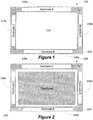
- Fig. 1 shows an electrode arrangement 100 that can be used for both, a 3D gesture detection system as described above and/or an additional touch detection system.
- Such an additional input system can be combined with another integrated input device of the processing system.
- the electrode arrangement is designed to include an "open" area 110 in which another input device (e.g., touch pad, track ball, keyboard, touchscreen, joystick, etc.) of the processing system might be arranged.
- a transmitter electrode 120 might be implemented in the form of a rectangular frame. According to various alternative embodiments, such a "frame” does not necessarily have to be rectangular, but could be elliptical, circular, or have any other frame-like shape.
- Various receiver electrodes 130a, b, c, d can be arranged in a plane above a transmitter plane in which the transmitter electrode is arranged according to an embodiment as shown in Fig. 1 . However, if more space is available, these electrodes can also be arranged in the same plane, for example, as the surrounding frame 120. According to some embodiments, the stacked layer arrangement as shown in Fig. 1 might be particularly beneficial in certain applications as it requires less real estate, which may be important, for example, if the device is added or retrofitted to an existing input device arranged in area 110.
- a multi-sensor arrangement for touch detection could be used instead of the 3D detection electrode arrangement shown in Fig. 1 .
- a multi-sensor arrangement could look similar to the arrangement shown in Fig. 1 , but without the transmission electrode 120.
- the transmission electrode 120 could be used as part of a capacitive touch detection arrangement, for example, forming an opposing electrode for touch electrodes 130a, b, c, d.
- Other touch detection electrode arrangements are of course possible.
- optical or acoustic sensor arrangements are possible according to other embodiments.
- Figs. 2-4 show various possible arrangements with such a rectangular sensor arrangement.
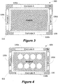
- the sensor arrangement is designed to surround a conventional touch pad 210 as known in particular from laptop computers and therefore provides for area 110 can accommodate the touchpad 210.
- the touchpad 210 may include one or more hardware buttons for select functions (not shown in Fig. 2 ), for example, which may be similar to left and right buttons on a computer mouse.
- Fig. 3 shows another embodiment, wherein a touch sensitive display 310 is arranged in the center area 110.
- a touch sensitive display 310 is arranged in the center area 110.
- Such displays are in common use in tablet computers, PDA's, smart phones, etc.
- Fig. 4 shows an example with a keyboard 410 arranged in the center area. While Fig. 4 shows a specific number of keys, the number of keys and key arrangement may vary depending on the application. Additionally, other input devices may be used according to various embodiments.
- the transmitter electrode 120 in a 3D sensor arrangement can also be split into more than one electrode.
- the number of receiving electrodes 130a, b, c, d that provide for individual signals is not limited to four.
- other applications might utilize a greater number of receiving electrodes, and still other applications might utilize fewer receiving electrodes.
- the transmitter electrode 120 is used to generate a quasi-static alternating electric near field and the receiving electrodes 130a, b, c, d are used to detect disturbances in such a field.
- the electrode arrangement when arranged in layers as shown in Figs. 1-5 , may comprise a non-conductive substrate on top of which the receiving electrodes 130 a, b, c, d are arranged.
- the transmitting electrode 120 may be arranged on a bottom side of such a substrate.
- a double sided printed circuit board may be used.
- other substrates may be used independent from multi-layer or single layer arrangement.
- the electrodes do not need to be formed in a top or bottom layer but could also be formed in one of the intermediate layers of a multi-layer substrate. All electrodes can be formed by a conductive layer such as a copper layer, which is typical for a printed circuit board. Thus, reception electrodes can be formed by etched structures in such a copper layer whereas the entire bottom copper layer or an inner layer may form the transmission electrode 120 as shown in Fig. 1 .
- certain areas on the top and/or bottom side may be used to place a respective controller component, such as an integrated circuit device, and/or other necessary components which can be directly connected with the electrodes via etched circuit paths, vias, etc.
- a respective controller component such as an integrated circuit device, and/or other necessary components which can be directly connected with the electrodes via etched circuit paths, vias, etc.
- FIG. 5 shows a block diagram of such a combined system. Again, the 3D sensor structure 500 is similar to those shown in Figs. 1-4 .
- the surrounded input device is generally depicted as input unit 510.
- a processor e.g., a microcontroller 520
- a processor is provided which is coupled with a human interface device (HID) interface controller 530 and a gesture controller 540, for example, the above mentioned MGC3130.
- HID interface controller is connected with input device 510 and gesture controller 540 is coupled with the transmission and reception electrodes 120, 130a, b, c, d.
- Gesture controller 520 may not be directly connected with the processor but only with HID controller 530.
- Processor 520 controls Gesture controller 540 in such an embodiment through HID controller 530.
- electrode sensors 130a, b, c, d are used to detect the approach of a user hand.
- the sensor information can be used for gesture recognition, 3D hand positioning and for various touch and tapping combinations.
- the electrode arrangement according to this embodiment is in a rectangular arrangement to fit around the touchpad ( Fig.1 ). However, other shapes are possible as discussed above. The electrode arrangement form can therefore be different for other input devices (e.g., circular for round input devices).
- the touchpad 210 in the middle of the sensor can work at the same time. Also combinations of the touchpad input information and the extended sensor arrangement can be used to trigger events.
- gesture combinations like a twice performed hand movement from the keyboard towards the lower edge of the touchpad (in case the touch pad is arranged below the keyboard, as typical for many laptop computers), will make the gesture input more reliable compared to a single performed gesture since typical hand movements not intended to trigger events may look the same to the sensor as those that are intended to trigger events.
- the input sensor electrodes 130a, b, c, d may be used to determine the position of the user's hand over time.
- the input device 510 can be:
- a 3D sensor arrangement 100, 200, 300, 400, 500 as shown in Figs. 1-5 may be used to determine the position of the user's hand over time.
- the sensor arrangement may have different types of sensors and can be:
- the sensors may be arranged in a similar fashion as shown with the electrodes in Figs. 1-5 .
- the actual sensor may not be arranged around the input device but placed in a position that allows the sensor to monitor the area or space above the input device.
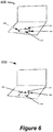
- Fig. 6 shows on top a first example of a laptop device 600 integrated trackpad 610 and three infrared sensors 620, 630, and 640 arranged around the trackpad 630.
- the bottom of Fig. 6 shows another example of a laptop device 650 with integrated trackpad 660 and three infrared sensors 670, 680, and 690 arranged above and along the top edge of the trackpad 660.
- Other arrangement for infrared sensors may apply.
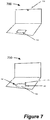
- Fig. 7 shows two examples of laptop devices 700 and 750 with integrated trackpad 710 and 760, respectively.
- the first embodiment 700 uses a camera 720 to detect the area above the trackpad 710.
- the second embodiment 750 uses three ultrasound sensors 770, 780, and 790 arranged around the trackpad 760 in similar fashion as in the embodiment 600. Again, other location for the sensors may apply to monitor the area above the trackpad 710, 760 or any other suitable input device.
- a specific embodiment of a capacitive / e-field input device may comprise a set of 4 individual receiving electrodes, including 2 vertically aligned electrodes (sensor electrodes 130a, b) and 2 horizontally aligned electrodes (sensor electrodes 130c, d).
- a gesture controller 540 for example the GestIC controller manufactured by the assignee of the present disclosure, four receiving electrodes 130 may be used in combination with one transmitting electrode structure 120 (stacked or in one layer).
- the four RX and the one TX electrodes 120, 130a, b, c, d may be used as separate touch detection electrodes.
- measurements may be used to extract from the raw signal (i.e., of the above sensors), amplitudes, distances from sensors, position and derivatives (e.g., first, second and higher order) over time, etc., as generated by movements of the user's hand.
- a classifier e.g., hidden Markov model, dynamic time wrapping, neural networks, vector machines, etc.
- deterministic classifiers e.g., general state machine
- a specific embodiment of a capacitive / e-field input device may comprise a set of 4 individual receiving electrodes, including 2 vertically aligned electrodes(sensor electrodes 130a, b) and 2 horizontally aligned electrodes (sensor electrodes 130c, d).
- four receiving electrodes 130 may be used in combination with one transmitting electrode structure 120 (stacked or in one layer).
- the four RX and the one TX electrodes 120, 130a, b, c, d may be used as separate touch detection electrodes.
- the sensor system 120, 130a, b, c, d detects the touch/proximity of the hand/palm of the user on all outer sides of the touchpad 210 or other input device 310, 410, 510.
- the multi-sensor information can be used to block the touchpad 210 or other input device 310, 410, 510, for example, during keyboard typing, to avoid cursor jumps.
- the proximity of the multi-electrode sensor arrangement 120, 130a, b, c, d can be used to wake up the processing device, such as a notebook/laptop computer, once the user approaches/is approaching the touchpad.
- the processing device such as a notebook/laptop computer
- gestures might also be used for device wake-up. For example, this could be done in a low power mode, which might be needed for wakeup functionality.
- the user may not notice at all, that the device was in an low power mode with reduced functionality, since the input device 210 can switch back to full working mode before the user is touching it.
- the multi-sensor arrangement 120, 130a, b, c, d can be used, according to one operating mode, to open/activate menus (e.g., a menu for function key controls, such as F1-F12, etc.) by touching, tapping or performing a defined hand movement.
- menus e.g., a menu for function key controls, such as F1-F12, etc.
- the multi-sensor arrangement 120, 130a, b, c, d can also be used to substitute shortcut key combinations or even single key functions by touch combinations or gestures performed above the touchpad.
- a user could twice perform a hand movement, from above the touchpad and moving toward the keyboard, to perform a task such as copying content, and likewise twice perform another hand movement from above the keyboard and moving toward the touchpad (i.e., away from the keyboard) to perform another task, such as pasting the copied content.
- specialty keys e.g., "CTRL,” ALT, "DEL,” etc.
- CRL CRL
- ALT ALT
- DEL DEL
- a left/right/left hand movement might be used for a delete function
- double hand movement from the keyboard towards touchpad might be used to close an application.
- Such sensor arrangement and decoding method may simplify the usage of existing user input devices and generate a new way of controlling devices.
- a combination of input device and surrounding sensor device can be used to provide additional functionality.
- a touch on a single finger/multi finger touchpad and a touch on an electrode of the surrounding sensor arrangement can be used to trigger, for example a scroll functionality.
- moving the finger on the touchpad while the second finger is on one of the surrounding electrodes can be used for horizontal and/or vertical scrolling.
- a touch on a single finger/multi finger touchpad and a touch on one of the electrodes of the surrounding electrode arrangement can be used to trigger a zoom functionality.
- moving the finger on touchpad while touching with a second finger one of the outer electrodes of the surrounding electrode arrangement causes a zooming function.
- other combinations and associated functions can be implemented according to various other embodiments.
- Fig. 8 shows a possible implementation of a lock input device function, that may be useful, for example during keyboard usage.
- the touch proximity information obtained from the surrounding electrodes 130a-d may be used to provide this functionality.
- the input device 510 for example, a touch pad 210, may be locked, for example, to avoid cursor jumps whenever electrode 130a and either electrode 130c or electrode 130d are touched at the same time.
- This kind of touch/approach pattern is likely when the user is using a 10 finger typing method and the touchpad with surrounding electrodes is below the keyboard.
- the palm of the left hand creates a touch/approach at the electrodes 130a and 130c and or the right hand creates a touch/approach on electrode 130a and 130d.
- other combinations of sensor electrodes may be used.
- a sequence of gestures may be considered as input action.
- a sequence of gestures helps to distinguish between a hand movement to interact with the device 210, 310 and 410 and an intended gesture as input information.
- a sequence of gestures can be a repetition of a single gesture or a sequence of different gestures.
- the time between gestures and thus the time for the sequence may get adjusted accordingly to create a unique interaction.
- the time between the gestures can be set to a predefined minimum limit and/or to a predefined maximum limit.
- the time for the gesture itself can be adjusted if the gesture itself has a duration.
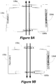
- Fig. 9A and 9B show a possible implementation of gesture sequence interpretation to perform a copy & paste function.
- a double performed non-touching hand movement starting over sensor 130b to sensor 130a would be interpreted as a copy or Ctrl + 'c' function.
- a double performed non-touching hand movement from sensor 130a to sensor 130b would initiate a paste or Ctrl + 'v' function.
- Fig. 10A and 9B shows possible gesture combinations for initiating opening of context menus, such as, volume and brightness control menus.
- a touch on sensor 130b and a double tap on sensor 130a may initiate such a function.
- a touch, indicated by the circle 810, on the touchpad or action on the input device 510 combined with a touch , tap, or double tap on one of the sensor electrodes 130d could initiate such a functionality.
- other combinations may be used.
- a certain proximity of the touch 810 and the combined electrode touch may be required according to some embodiments.
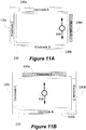
- Fig. 11A and 11B shows the above mentioned scroll function in more detail.
- a combination of a touch of one of the electrodes 130a-d, for example, electrode 130d, and movement 910 of another or multiple finger(s) on the touch pad 210 could be used for a scrolling function as shown in Fig. 11A or if the movement 920 is combined with another electrode, for example, electrode 130a, as shown in Fig. 11B a zooming function will be performed.
- other combinations may be used according to various embodiments.
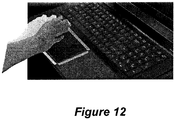
- Fig. 12 shows yet another possible implementation to perform a wake-up from standby/sleep/screensaver mode.
- the proximity data obtained from one or more electrodes 130a-d can be used to wake up the device if a specific movement/gesture is performed.
- a backlight of the keyboard may be activated if a specific touch gesture or non-touching gesture is performed using the electrodes 130a-d.
- an existing hardware can be used and controlled in such a way that it allows a so-called virtual formation of electrodes A, B, C, D similar as those shown in Figs. 1-5 .
- the electrodes A, B, C, D are not formed as separate hardware around an existing input device.
- a touchpad 1110 provides for a matrix of electrodes that allow, for example, self and mutual capacitance measurements using a capacitive touch controller 1120. Similar as in the embodiment shown in Fig. 5 , the capacitive touch controller is coupled with processor 1130. Touch controller 1120 and processor 1130 may be integrated in a microcontroller or may be part of a system on chip or any other suitable sub-system of a processing device, such as, e.g. a laptop or tablet computer. The touchpad 1110 can be controlled in such a way that, for example, only the capacitive electrodes adjacent to the outer edges are used in measurements.
- the electrodes forming the touch sensitive surface can be separately controlled in such a way, that individual areas of the sensor can be activated, for example, switched together to form a specific area. This may be performed in a time multiplex mode for each simulated electrode A, B, C, D according to some embodiments.
- a capacitive touchpad having a matrix structure as shown in Fig. 13 self- or mutual capacitance measurement may be used to simulate electrodes A, B, C, D.
- a top row can be selected as a virtual electrode A.
- a bottom row can be used for electrode B, an outer most left column for electrode C and an outer most right column for electrode D.
- Other selection can be made depending on the measurement principle to form the virtual electrodes A, B, C, D and they may not necessarily have the shape as shown in Fig. 8 .
- the virtual electrodes A, B, C, D may allow for the same principles as discussed above. Thus, depending on the sensitivity of the capacitive measurements of the touch controller 620, they may be used for 3D measurements using an electric field generated, for example, by a common electrode arranged under the matrix. Alternatively, they can be used as touch sensors.
- the designated function of the input device may be multiplexed with this additional senor function provided by the virtual electrodes A, B, C, D. Thus, the same functionality as discussed above can be provided by such a device.
- Figs. 1-5 Other input devices may also be capable to simulate the surrounding sensor device as shown in Figs. 1-5 .
- Figs. 13 further embodiments using the principles as discussed with respect to Fig. 13 are not limited to a touchpad but could be extended to other suitable input devices, for example but not limited to optical and acoustical sensor devices, that allow for a two- or three dimensional sensor detection.
Landscapes
- Engineering & Computer Science (AREA)
- General Engineering & Computer Science (AREA)
- Theoretical Computer Science (AREA)
- Physics & Mathematics (AREA)
- Human Computer Interaction (AREA)
- General Physics & Mathematics (AREA)
- Acoustics & Sound (AREA)
- Position Input By Displaying (AREA)
- User Interface Of Digital Computer (AREA)
Description
- The present disclosure relates to a human device interfaces, in particular to three-dimensional (3D) gesture detection.
- Processing devices, such as personal computers, in particular mobile computer, such as laptop computers, tablet computers, etc., usually provide for a variety of input devices, such as a keyboard, touch screen, track pad, mouse, etc. These input devices generally provide for a two-dimensional input device that requires touching and/or manual operation.
- US Patent Application Publication
US 2011/179368 discloses a system that allows for 3D view of file structure. European Patent ApplicationEP 2660685 discloses an input device, input control method, program and electronic apparatus which can detect a hover and a touch operation. US Patent Application PublicationUS 2011/0221776 discloses a display input device and navigation device. US Patent Application PublicationUS 2011/0029913 discloses a navigation system and user interface for directing a control action. - US Patent Application Publication
US 2013/147833 A1 discloses a system and a method according to the pre-characterizing portion of claims 1 and 2, respectively. - There exists a need for an improved input device that allows for enhancing the functionality of existing input devices. This and other objects can be achieved by a system and method as defined in the independent claims. Further enhancements are characterized in the dependent claims.
- According to an embodiment, a system comprises a processing system, an input device integrated within the processing system and coupled with the processing system, and a sensor arrangement integrated with the processing system and configured to monitor an area above said input device, and a controller coupled with the sensor arrangement to detect predefined input actions, wherein the controller is coupled with the processing system and wherein the predefined input actions are combined with inputs from said input device.
- According to a further embodiment, the sensor arrangement can be an electrode arrangement comprising a plurality of electrodes arranged such that the electrodes surround the input device. According to a further embodiment, the electrode arrangement can be configured to detect a gesture performed in a 3D space above the electrode arrangement, wherein the electrode arrangement comprises a transmission electrode for generating a quasi-static electric field and a plurality of reception electrodes arranged around said input device. According to a further embodiment, the electrode arrangement may comprise a plurality of electrode sensors around said input device that can be configured to operate as touch sensors arranged. According to a further embodiment, the electrode sensors around said input device can be configured to operate as non-touching gesture detection sensors in a first operating mode and as touch sensors in a second operating mode. According to a further embodiment, the operating modes may be time-multiplexed. According to a further embodiment, the input actions can be used to block or unblock said input device. According to a further embodiment, the input actions can be used to perform predefined functions of the processing system. According to a further embodiment, the input actions may consist of a sequence of input actions. According to a further embodiment, a sequence may comprise multiple identical input actions. According to a further embodiment, the identical input actions may be moving a hand vertically across the input device twice. According to a further embodiment, a first predefined function is a copy function and a second predefined function is a paste function. According to a further embodiment, an input action combined with an input on said input device may perform a predefined function of the processing system. According to a further embodiment, the input device can be a touchpad and the input action is a touch detection on an electrode of said electrode arrangement and the input from said input device is a touch movement performed on said touch pad. According to a further embodiment, the electrode arrangement may comprise a plurality of electrodes and the touched electrode defines the predefined function which is selected from the group consisting of horizontal scrolling, vertical scrolling, and zooming.
- According to a further embodiment of the above method, the sensor arrangement can be an electrode arrangement comprising a plurality of electrodes arranged such that the electrodes surround the input device. According to a further embodiment of the above method, the electrode arrangement may be configured to detect a non-touching gesture performed in a 3D space above the electrode arrangement, wherein the electrode arrangement comprises a transmission electrode for generating a quasi-static electric field and a plurality of reception electrodes arranged around said input device. According to a further embodiment of the above method, the electrode arrangement may comprise a plurality of electrode sensors around said input device, and the method may comprise configuring the electrode sensors to operate as touch sensors. According to a further embodiment of the above method, the method may comprise configuring the electrode sensors around said input device to operate as non-touching gesture detection sensors in a first operating mode and as touch sensors in a second operating mode. According to a further embodiment of the above method, the operating modes may be time-multiplexed. According to a further embodiment of the above method, the input actions may be used to block or unblock said input device. According to a further embodiment of the above method, the input actions may be used to perform predefined functions of the processing system. According to a further embodiment of the above method, the input actions may consist of a sequence of input actions. According to a further embodiment of the above method, a sequence may comprise multiple identical input actions. According to a further embodiment of the above method, the identical input actions can be moving a hand vertically across the input device twice. According to a further embodiment of the above method, a first predefined function can be a copy function and a second predefined function is a paste function. According to a further embodiment of the above method, an input action combined with an input on said input device may perform a predefined function of the processing system. According to a further embodiment of the above method, the input device may be a touchpad and the input action may be a touch detection on an electrode of said electrode arrangement and the input from said input device is a touch movement performed on said touch pad. According to a further embodiment of the above method, the electrode arrangement may comprise a plurality of electrodes and the touched electrode defines the predefined function which is selected from the group consisting of horizontal scrolling, vertical scrolling, and zooming.
-
Fig. 1 shows an embodiment of a sensor arrangement; -
Fig. 2 shows the embodiment ofFig. 1 combined with a trackpad; -
Fig. 3 shows the embodiment ofFig. 1 combined with a display; -
Fig. 4 shows the embodiment ofFig. 1 combined with a keyboard; -
Fig. 5 shows a block diagram of circuitry combined with the embodiment ofFigs. 1-4 ; -
Figs. 6 and7 show embodiments with different types of gesture detection systems; -
Figs. 8-12 show possible implementations of various combinations of touch and gestures of a input device and an additional sensor arrangement according toFig. 1 ; -
Fig. 13 shows another embodiment of a virtual sensor arrangement formed in an existing capacitive touch sensor area. - According to various exemplary embodiments, an additional sensor input device can be combined with existing conventional input devices and an improved operating method can be provided to enhance the functionality of these input devices. For example, a 3D detection system or an additional touch detection system or any other type of input sensor could be integrated within an input device of a processing system. According to an embodiment, a good integration spot for a 3D gesture detection sensor, for example, an electric field or "e-field" sensor, or an additional touch or sensor detection system in a notebook or laptop computer could be beneficial, particularly where intuitive gestures might improve the current user interface.
- For example, according to one embodiment, in the case of 3D detection systems of the e-field type, having an electrode design without using a transmitter electrode covering the whole sensing area allows for an easy integration of the additional sensor. The electrode design shown in
Fig. 1 , for example, provides a layout that locates electrodes around a perimeter of an input device, according to some embodiments, for example, a touchpad, and therefore an already existing notebook/laptop structure design needs no significant change or alteration to accommodate these electrodes. This sort of design brings the sensor into the space where the user has his hand for touchpad control. Also, it is possible to avoid having to multiplex electrode input signals with the touchpad input signals. According to various embodiments, the gesture integration can be performed, for example, to substitute user interactions that may not be convenient at a given moment (e.g., key shortcuts). - Thus, a multi sensor arrangement (e.g., touch and/or 3D sensing) surrounding an existing input device is proposed according to various embodiments. The electrode arrangement can be designed to typically enclose/surround mechanical input devices like keypads, non-touch displays, touch displays, single touch touchpads and multi touch touchpads. The electrode sensor arrangement can be designed to enable extended user interface solutions with single-touch, multi-touch and/or 3D hand movement over time.
- The additional input device surrounding an existing input device may provide for a three-dimensional gesture detection according to various embodiments. Such a more advanced sensor arrangement is for example a three-dimensional gesture detection system that does not require any touch. According to some embodiments, a three-dimensional electric field sensor controller introduced by Applicant produces through a dedicated sensor arrangement a quasi-static electric field, for example, using a 100 kHz signal fed to a transmitting electrode. Such an electric field might extend vertically more than 10 cm from the sensor arrangement generating the field. A user can enter this field without touching the device, for example with a hand, and gestures performed by the user will disturb the electric field. Such distortions can then be measured, for example, using receiving electrodes, and dynamic and static characteristics determined by the arrangement can be used to conclude which type of gesture/input command has been performed. The device can further be controlled to also operate as a touch sensor. In particular when time multiplexing is used, such a sensor system can perform both, non-touching gesture detection and touch detection.
-
Fig. 1 shows anelectrode arrangement 100 that can be used for both, a 3D gesture detection system as described above and/or an additional touch detection system. Such an additional input system can be combined with another integrated input device of the processing system. The electrode arrangement is designed to include an "open"area 110 in which another input device (e.g., touch pad, track ball, keyboard, touchscreen, joystick, etc.) of the processing system might be arranged. To allow such an arrangement, atransmitter electrode 120 might be implemented in the form of a rectangular frame. According to various alternative embodiments, such a "frame" does not necessarily have to be rectangular, but could be elliptical, circular, or have any other frame-like shape.Various receiver electrodes 130a, b, c, d can be arranged in a plane above a transmitter plane in which the transmitter electrode is arranged according to an embodiment as shown inFig. 1 . However, if more space is available, these electrodes can also be arranged in the same plane, for example, as the surroundingframe 120. According to some embodiments, the stacked layer arrangement as shown inFig. 1 might be particularly beneficial in certain applications as it requires less real estate, which may be important, for example, if the device is added or retrofitted to an existing input device arranged inarea 110. - According to other exemplary embodiments, a multi-sensor arrangement for touch detection could be used instead of the 3D detection electrode arrangement shown in
Fig. 1 . For example, such a multi-sensor arrangement could look similar to the arrangement shown inFig. 1 , but without thetransmission electrode 120. However, according to other embodiments, thetransmission electrode 120 could be used as part of a capacitive touch detection arrangement, for example, forming an opposing electrode fortouch electrodes 130a, b, c, d. Other touch detection electrode arrangements are of course possible. Moreover, optical or acoustic sensor arrangements are possible according to other embodiments. -
Figs. 2-4 show various possible arrangements with such a rectangular sensor arrangement. InFig. 2 , the sensor arrangement is designed to surround aconventional touch pad 210 as known in particular from laptop computers and therefore provides forarea 110 can accommodate thetouchpad 210. Thetouchpad 210 may include one or more hardware buttons for select functions (not shown inFig. 2 ), for example, which may be similar to left and right buttons on a computer mouse. -
Fig. 3 shows another embodiment, wherein a touchsensitive display 310 is arranged in thecenter area 110. Such displays are in common use in tablet computers, PDA's, smart phones, etc. -
Fig. 4 shows an example with akeyboard 410 arranged in the center area. WhileFig. 4 shows a specific number of keys, the number of keys and key arrangement may vary depending on the application. Additionally, other input devices may be used according to various embodiments. - The
transmitter electrode 120 in a 3D sensor arrangement can also be split into more than one electrode. Moreover, the number of receivingelectrodes 130a, b, c, d that provide for individual signals is not limited to four. For example, other applications might utilize a greater number of receiving electrodes, and still other applications might utilize fewer receiving electrodes. Thetransmitter electrode 120 is used to generate a quasi-static alternating electric near field and the receivingelectrodes 130a, b, c, d are used to detect disturbances in such a field. The electrode arrangement, when arranged in layers as shown inFigs. 1-5 , may comprise a non-conductive substrate on top of which the receivingelectrodes 130 a, b, c, d are arranged. The transmittingelectrode 120 may be arranged on a bottom side of such a substrate. For example, a double sided printed circuit board may be used. However, other substrates may be used independent from multi-layer or single layer arrangement. The electrodes do not need to be formed in a top or bottom layer but could also be formed in one of the intermediate layers of a multi-layer substrate. All electrodes can be formed by a conductive layer such as a copper layer, which is typical for a printed circuit board. Thus, reception electrodes can be formed by etched structures in such a copper layer whereas the entire bottom copper layer or an inner layer may form thetransmission electrode 120 as shown inFig. 1 . However, if implemented on a printed circuit board, certain areas on the top and/or bottom side may be used to place a respective controller component, such as an integrated circuit device, and/or other necessary components which can be directly connected with the electrodes via etched circuit paths, vias, etc. - An example of an integrated circuit device that can be connected to such an electrode structure 100-400 to be used in a 3D detection system is a gesture evaluation controller MGC3130 also called GestIC® manufactured by Applicant, a data sheet for which is available from Applicant. Achievable range is an important factor in electric near field sensing and in GestIC® three-dimensional gesture recognition, and in tracking technology in particular.
Fig. 5 shows a block diagram of such a combined system. Again, the3D sensor structure 500 is similar to those shown inFigs. 1-4 . The surrounded input device is generally depicted asinput unit 510. A processor, e.g., amicrocontroller 520, is provided which is coupled with a human interface device (HID)interface controller 530 and agesture controller 540, for example, the above mentioned MGC3130. HID interface controller is connected withinput device 510 andgesture controller 540 is coupled with the transmission andreception electrodes HID controller 530 andGesture controller 540,Gesture controller 520 may not be directly connected with the processor but only withHID controller 530.Processor 520 controlsGesture controller 540 in such an embodiment throughHID controller 530. - As shown in
Figs. 1-5 ,electrode sensors 130a, b, c, d are used to detect the approach of a user hand. The sensor information can be used for gesture recognition, 3D hand positioning and for various touch and tapping combinations. The electrode arrangement according to this embodiment is in a rectangular arrangement to fit around the touchpad (Fig.1 ). However, other shapes are possible as discussed above. The electrode arrangement form can therefore be different for other input devices (e.g., circular for round input devices). Thetouchpad 210 in the middle of the sensor can work at the same time. Also combinations of the touchpad input information and the extended sensor arrangement can be used to trigger events. Using gesture combinations like a twice performed hand movement from the keyboard towards the lower edge of the touchpad (in case the touch pad is arranged below the keyboard, as typical for many laptop computers), will make the gesture input more reliable compared to a single performed gesture since typical hand movements not intended to trigger events may look the same to the sensor as those that are intended to trigger events. - In a 3D sensor arrangement as shown in
Figs. 1-5 , theinput sensor electrodes 130a, b, c, d may be used to determine the position of the user's hand over time. Theinput device 510 can be: - optical (e. g. camera (time of flight, stereoscopic), IR sensors and transmitter,
- acoustical (ultrasound),
- capacitive/e-field measurement (e.g., mutual, self-measurement of electrodes arranged in a matrix), or
- any other suitable input device such as mechanical input devices (e.g., keyboards, trackball, etc.).
- A
3D sensor arrangement Figs. 1-5 , may be used to determine the position of the user's hand over time. According to various other embodiments, the sensor arrangement may have different types of sensors and can be: - optical (e.g. camera (time of flight, stereoscopic), IR sensors and transmitter,
- acoustical (ultrasound).
- In these embodiments, the sensors may be arranged in a similar fashion as shown with the electrodes in
Figs. 1-5 . However, in some technologies, such as sensors using a camera, the actual sensor may not be arranged around the input device but placed in a position that allows the sensor to monitor the area or space above the input device. For example,Fig. 6 shows on top a first example of alaptop device 600integrated trackpad 610 and threeinfrared sensors trackpad 630. The bottom ofFig. 6 shows another example of alaptop device 650 withintegrated trackpad 660 and threeinfrared sensors trackpad 660. Other arrangement for infrared sensors may apply. -
Fig. 7 shows two examples oflaptop devices integrated trackpad first embodiment 700 uses acamera 720 to detect the area above thetrackpad 710. Thesecond embodiment 750 uses threeultrasound sensors trackpad 760 in similar fashion as in theembodiment 600. Again, other location for the sensors may apply to monitor the area above thetrackpad - As shown in
Figs. 1-5 , a specific embodiment of a capacitive / e-field input device may comprise a set of 4 individual receiving electrodes, including 2 vertically aligned electrodes (sensor electrodes 130a, b) and 2 horizontally aligned electrodes (sensor electrodes 130c, d). When using agesture controller 540, for example the GestIC controller manufactured by the assignee of the present disclosure, four receiving electrodes 130 may be used in combination with one transmitting electrode structure 120 (stacked or in one layer). As mentioned above, in a capacitive self-measurement system, the four RX and the oneTX electrodes - With the
sensor electrodes 130a, b, c, d, measurements may be used to extract from the raw signal (i.e., of the above sensors), amplitudes, distances from sensors, position and derivatives (e.g., first, second and higher order) over time, etc., as generated by movements of the user's hand. - Usage of such derived features as input of a classifier (e.g., hidden Markov model, dynamic time wrapping, neural networks, vector machines, etc.), and deterministic classifiers (e.g., general state machine) to classify the hand movements to a predefined (trained) set of gestures.
- As shown in
Figs. 1-5 , a specific embodiment of a capacitive / e-field input device may comprise a set of 4 individual receiving electrodes, including 2 vertically aligned electrodes(sensor electrodes 130a, b) and 2 horizontally aligned electrodes (sensor electrodes 130c, d). When using aGestIC gesture controller 540, four receiving electrodes 130 may be used in combination with one transmitting electrode structure 120 (stacked or in one layer). As mentioned above, in a capacitive self-measurement system, the four RX and the oneTX electrodes - The
sensor system touchpad 210 orother input device touchpad 210 orother input device - The proximity of the
multi-electrode sensor arrangement input device 210 can switch back to full working mode before the user is touching it. - The
multi-sensor arrangement - According to other operating mode, the
multi-sensor arrangement - Additionally, specialty keys, e.g., "CTRL," ALT, "DEL," etc., are sometime placed at different positions, which often varies among different laptop models. In such cases, the user may have to search for the desired specialty key. However, with the intuitive gesture/touch substitution of shortcuts as described above, the user may not have to search for such keys anymore.
- Other examples according to various embodiments or operating modes are also possible. For example, a left/right/left hand movement might be used for a delete function, or double hand movement from the keyboard towards touchpad might be used to close an application. Generally, it is possible to link any device function to some combination of user input gesture/touch/button/key press/etc. Such sensor arrangement and decoding method may simplify the usage of existing user input devices and generate a new way of controlling devices.
- For example, a combination of input device and surrounding sensor device can be used to provide additional functionality. For example, a touch on a single finger/multi finger touchpad and a touch on an electrode of the surrounding sensor arrangement can be used to trigger, for example a scroll functionality. In this example, moving the finger on the touchpad while the second finger is on one of the surrounding electrodes can be used for horizontal and/or vertical scrolling. According to another functionality, a touch on a single finger/multi finger touchpad and a touch on one of the electrodes of the surrounding electrode arrangement can be used to trigger a zoom functionality. Here, moving the finger on touchpad while touching with a second finger one of the outer electrodes of the surrounding electrode arrangement causes a zooming function. Of course other combinations and associated functions can be implemented according to various other embodiments.
-
Fig. 8 , for example, shows a possible implementation of a lock input device function, that may be useful, for example during keyboard usage. Here the touch proximity information obtained from the surroundingelectrodes 130a-d may be used to provide this functionality. If a touch/approach at one ormore sensors 130a, b, c, d is detected, theinput device 510, for example, atouch pad 210, may be locked, for example, to avoid cursor jumps wheneverelectrode 130a and eitherelectrode 130c orelectrode 130d are touched at the same time. This kind of touch/approach pattern is likely when the user is using a 10 finger typing method and the touchpad with surrounding electrodes is below the keyboard. The palm of the left hand creates a touch/approach at theelectrodes electrode - A sequence of gestures may be considered as input action. A sequence of gestures helps to distinguish between a hand movement to interact with the
device -
Fig. 9A and 9B show a possible implementation of gesture sequence interpretation to perform a copy & paste function. Here, as shown inFig. 9A , a double performed non-touching hand movement starting oversensor 130b tosensor 130a would be interpreted as a copy or Ctrl + 'c' function. Likewise, as shown inFig. 9B , a double performed non-touching hand movement fromsensor 130a tosensor 130b would initiate a paste or Ctrl + 'v' function. -
Fig. 10A and9B shows possible gesture combinations for initiating opening of context menus, such as, volume and brightness control menus. As shown inFig. 10A , a touch onsensor 130b and a double tap onsensor 130a may initiate such a function. Alternatively or in addition, as shown inFig. 10B , a touch, indicated by thecircle 810, on the touchpad or action on theinput device 510 combined with a touch , tap, or double tap on one of thesensor electrodes 130d could initiate such a functionality. Again, other combinations may be used. Moreover, a certain proximity of thetouch 810 and the combined electrode touch may be required according to some embodiments. -
Fig. 11A and 11B shows the above mentioned scroll function in more detail. Here, a combination of a touch of one of theelectrodes 130a-d, for example,electrode 130d, andmovement 910 of another or multiple finger(s) on thetouch pad 210 could be used for a scrolling function as shown inFig. 11A or if themovement 920 is combined with another electrode, for example,electrode 130a, as shown inFig. 11B a zooming function will be performed. Again other combinations may be used according to various embodiments. -
Fig. 12 shows yet another possible implementation to perform a wake-up from standby/sleep/screensaver mode. For example, the proximity data obtained from one ormore electrodes 130a-d can be used to wake up the device if a specific movement/gesture is performed. According to another function, a backlight of the keyboard may be activated if a specific touch gesture or non-touching gesture is performed using theelectrodes 130a-d. - According to yet further embodiments, an existing hardware can be used and controlled in such a way that it allows a so-called virtual formation of electrodes A, B, C, D similar as those shown in
Figs. 1-5 . Thus, in these embodiments, the electrodes A, B, C, D are not formed as separate hardware around an existing input device. - For example, in the embodiment shown in
Fig. 13 , atouchpad 1110 provides for a matrix of electrodes that allow, for example, self and mutual capacitance measurements using acapacitive touch controller 1120. Similar as in the embodiment shown inFig. 5 , the capacitive touch controller is coupled withprocessor 1130.Touch controller 1120 andprocessor 1130 may be integrated in a microcontroller or may be part of a system on chip or any other suitable sub-system of a processing device, such as, e.g. a laptop or tablet computer. Thetouchpad 1110 can be controlled in such a way that, for example, only the capacitive electrodes adjacent to the outer edges are used in measurements. In other words, the electrodes forming the touch sensitive surface can be separately controlled in such a way, that individual areas of the sensor can be activated, for example, switched together to form a specific area. This may be performed in a time multiplex mode for each simulated electrode A, B, C, D according to some embodiments. For a capacitive touchpad having a matrix structure as shown inFig. 13 , self- or mutual capacitance measurement may be used to simulate electrodes A, B, C, D. For example, a top row can be selected as a virtual electrode A. Similarly, a bottom row can be used for electrode B, an outer most left column for electrode C and an outer most right column for electrode D. Other selection can be made depending on the measurement principle to form the virtual electrodes A, B, C, D and they may not necessarily have the shape as shown inFig. 8 . - The virtual electrodes A, B, C, D may allow for the same principles as discussed above. Thus, depending on the sensitivity of the capacitive measurements of the
touch controller 620, they may be used for 3D measurements using an electric field generated, for example, by a common electrode arranged under the matrix. Alternatively, they can be used as touch sensors. The designated function of the input device may be multiplexed with this additional senor function provided by the virtual electrodes A, B, C, D. Thus, the same functionality as discussed above can be provided by such a device. - Other input devices may also be capable to simulate the surrounding sensor device as shown in
Figs. 1-5 . Thus, further embodiments using the principles as discussed with respect toFig. 13 are not limited to a touchpad but could be extended to other suitable input devices, for example but not limited to optical and acoustical sensor devices, that allow for a two- or three dimensional sensor detection.
Claims (14)
- A system comprising:a processing system comprising a processor (520);an input device (510) integrated within the processing system and coupled with the processor (520); anda sensor arrangement (500) comprising a plurality of sensing electrodes (130a..d) and being separate from said input device and integrated with the processing system and configured to monitor an area above said input device (510) for detection of non-touching gestures, and a controller (540) coupled with the sensor arrangement (500) to detect said non-touching gestures, wherein the controller (540) is coupled with the processor (520),characterized in that
the controller (540) is further configured to detect touches of the sensing electrodes (130a..d) of the sensor arrangement (500), wherein the system is further configured to detect a combination of a touch of at least one of the sensing electrodes (130a..d) and an input from said input device to trigger a function in the processing system, wherein the input is performed while the touch of at least one of the sensing electrodes (130a..d) is performed. - A method for operating a data processing device, wherein the data processing device comprises an input device (510) integrated within a processing system; the method comprising the steps of:integrating a sensor arrangement (500) comprising a plurality of sensing electrodes (130a..d) and being separate from said input device within the data processing device such that an area surrounding said input device (510) is monitored by the sensor arrangement (500) to detect non-touching gestures,detecting non-touching gestures by a controller (540) coupled with the electrode arrangement (500),characterized by
detecting a touch of at least one of the sensing electrodes (130a..d) of the sensor arrangement (500) by the controller (540);
combining the detected touch with an input generated by said input device (510) to trigger a function in the processing system, wherein the input is performed while the touch of at least one of the sensing electrodes (130a..d) is performed. - The system according to claim 1 or the method according to claim 2, wherein the plurality of sensing electrodes (120, 130) are arranged on a frame-like substrate such that the electrodes (120, 130) surround the input device (510).
- The system or method according to claim 3, wherein the capacitive electrode arrangement (500) is configured to detect a non-touching gesture performed in a 3D space above the capacitive electrode arrangement (500), wherein the capacitive electrode arrangement (500) further comprises a transmission electrode (120) for generating a quasi-static electric field and the plurality of sensing electrodes (130) arranged around said input device (510).
- The system or method according to claim 3, wherein the plurality of sensing electrodes (130) are arranged around said input device (510).
- The system or method according to claim 5, wherein the sensing electrodes (130) around said input device (510) can be configured to operate as non-touching gesture detection sensors in a first operating mode and as touch sensors in a second operating mode.
- The system or method according to claim 6, wherein the operating modes are time-multiplexed.
- The system or method according to one of the preceding claims, wherein input actions detected by the controller (540) are used to block or unblock said input device (510).
- The system or method according to one of the preceding claims, wherein input actions detected by the controller (540) are gestures from a plurality of predefined gestures, wherein when a gesture has been detected, a predefined function associated with said gesture is performed within the processing system.
- The system or method according to claim 8 to 9, wherein the input actions consist of a sequence of input actions or gestures.
- The system or method according to claim 10, wherein the sequence comprises multiple identical input actions or gestures, preferably moving a hand vertically across the input device twice.
- The system or method according to claim 11, wherein the predefined function is a copy function or a paste function.
- The system or method according to one of the preceding claims 5-12, wherein the input from or generated by said input device (510) is a touch movement performed on a touch pad (210).
- The system or method according to claim 13, wherein the processing system is configured to determine a function which is selected from the group consisting of horizontal scrolling, vertical scrolling, and zooming when at least one of the sensing electrodes (130a..d) is touched.
Applications Claiming Priority (3)
| Application Number | Priority Date | Filing Date | Title |
|---|---|---|---|
| US201461947112P | 2014-03-03 | 2014-03-03 | |
| US14/596,120 US9921739B2 (en) | 2014-03-03 | 2015-01-13 | System and method for gesture control |
| PCT/US2015/018226 WO2015134347A1 (en) | 2014-03-03 | 2015-03-02 | System and method for gesture control |
Publications (2)
| Publication Number | Publication Date |
|---|---|
| EP3114555A1 EP3114555A1 (en) | 2017-01-11 |
| EP3114555B1 true EP3114555B1 (en) | 2020-04-29 |
Family
ID=54006769
Family Applications (1)
| Application Number | Title | Priority Date | Filing Date |
|---|---|---|---|
| EP15710352.4A Active EP3114555B1 (en) | 2014-03-03 | 2015-03-02 | System and method for gesture control |
Country Status (7)
| Country | Link |
|---|---|
| US (2) | US9921739B2 (en) |
| EP (1) | EP3114555B1 (en) |
| JP (1) | JP6564383B2 (en) |
| KR (1) | KR102388791B1 (en) |
| CN (1) | CN105980974B (en) |
| TW (1) | TWI648662B (en) |
| WO (1) | WO2015134347A1 (en) |
Families Citing this family (20)
| Publication number | Priority date | Publication date | Assignee | Title |
|---|---|---|---|---|
| US10108292B2 (en) * | 2015-04-22 | 2018-10-23 | Microchip Technology Incorporated | Capacitive sensor system with multiple transmit electrodes |
| US10963157B2 (en) * | 2016-05-12 | 2021-03-30 | Lsi Industries, Inc. | Outdoor ordering system with interactive menu elements |
| CN106502574A (en) * | 2016-12-09 | 2017-03-15 | 成都前锋电子有限责任公司 | A kind of gestural control system and the gas heater containing the system |
| KR102355422B1 (en) * | 2017-05-23 | 2022-01-26 | 현대자동차주식회사 | Methods and apparatus for preventing misreading of touch pad |
| JP7041387B2 (en) * | 2017-09-27 | 2022-03-24 | カシオ計算機株式会社 | Parameter control device, electronic musical instrument, parameter control method and control program |
| US20200241694A1 (en) * | 2017-12-04 | 2020-07-30 | Mitsubishi Electric Corporation | Proximity detection device and proximity detection method |
| CN109917993A (en) * | 2017-12-13 | 2019-06-21 | 华硕电脑股份有限公司 | Control method, electronic device and non-instantaneous computer-readable recording medium |
| CN108768373A (en) * | 2018-07-03 | 2018-11-06 | 珠海进田电子科技有限公司 | A kind of novel line control machine of gesture control |
| JP7120725B2 (en) * | 2018-11-14 | 2022-08-17 | アルパイン株式会社 | ELECTRONIC DEVICE WITH TOUCH PANEL, BASELINE VALUE UPDATE METHOD AND UPDATE PROGRAM |
| US10949021B2 (en) * | 2019-03-08 | 2021-03-16 | Chargepoint, Inc. | Electric field touchscreen |
| US20220236827A1 (en) * | 2019-05-31 | 2022-07-28 | Lenovo (Beijing) Limited | Electronic apparatus and data processing method |
| CN110187795B (en) * | 2019-05-31 | 2021-03-19 | 联想(北京)有限公司 | Data processing method and electronic equipment |
| CN110187796B (en) * | 2019-05-31 | 2021-07-16 | 联想(北京)有限公司 | Electronic equipment and data processing method |
| US11567562B2 (en) * | 2019-06-28 | 2023-01-31 | Ncr Corporation | Self-checkout terminal sleep and wake operations |
| TWI779310B (en) * | 2019-09-26 | 2022-10-01 | 華碩電腦股份有限公司 | Control method of electronic device |
| US11504610B2 (en) * | 2020-02-14 | 2022-11-22 | Valve Corporation | Dynamically enabling or disabling controls of a controller |
| JP7378902B2 (en) | 2020-03-31 | 2023-11-14 | アルパイン株式会社 | Operation control device |
| US20240012170A1 (en) * | 2021-03-03 | 2024-01-11 | Guardian Glass, LLC | Systems and/or methods for creating and passively detecting changes in electrical fields |
| US11579679B2 (en) * | 2021-05-12 | 2023-02-14 | Microsoft Technology Licensing, Llc | Determining opening/closing of computing device |
| DE102022102295A1 (en) * | 2022-02-01 | 2023-08-03 | epitome GmbH | Method for controlling a cleaning device |
Citations (1)
| Publication number | Priority date | Publication date | Assignee | Title |
|---|---|---|---|---|
| US20130147833A1 (en) * | 2011-12-09 | 2013-06-13 | Ident Technology Ag | Electronic Device with a User Interface that has more than Two Degrees of Freedom, the User Interface Comprising a Touch-Sensitive Surface and Contact-Free Detection Means |
Family Cites Families (32)
| Publication number | Priority date | Publication date | Assignee | Title |
|---|---|---|---|---|
| ATE345539T1 (en) * | 1998-03-24 | 2006-12-15 | Toshiba Kk | IC CARD WITH CONTACT AND CONTACTLESS INTERFACES |
| TW200601067A (en) * | 2004-06-21 | 2006-01-01 | Inventec Corp | Interactive method of electronic apparatus |
| US9141254B2 (en) | 2005-11-12 | 2015-09-22 | Orthosensor Inc | Navigation system and user interface for directing a control action |
| DE202007018940U1 (en) * | 2006-08-15 | 2009-12-10 | N-Trig Ltd. | Motion detection for a digitizer |
| DE112009000684A5 (en) * | 2008-03-26 | 2011-05-26 | Ident Technology Ag | System and method for multidimensional gesture evaluation |
| JP5231571B2 (en) * | 2008-12-04 | 2013-07-10 | 三菱電機株式会社 | Display input device and navigation device |
| CN102117145B (en) * | 2009-12-30 | 2013-09-25 | 宏正自动科技股份有限公司 | Multi-computer management system and control method thereof |
| US10007393B2 (en) | 2010-01-19 | 2018-06-26 | Apple Inc. | 3D view of file structure |
| US20110193818A1 (en) * | 2010-02-05 | 2011-08-11 | Edamak Corporation | Proximity-sensing panel |
| JP5882232B2 (en) * | 2010-02-10 | 2016-03-09 | マイクロチップ テクノロジー ジャーマニー ゲーエムベーハー | System and method for generation of signals correlated with manual input action |
| DE102010007455A1 (en) * | 2010-02-10 | 2011-08-11 | Ident Technology AG, 82234 | System and method for contactless detection and recognition of gestures in a three-dimensional space |
| US8432301B2 (en) * | 2010-08-10 | 2013-04-30 | Mckesson Financial Holdings | Gesture-enabled keyboard and associated apparatus and computer-readable storage medium |
| US9135503B2 (en) * | 2010-11-09 | 2015-09-15 | Qualcomm Incorporated | Fingertip tracking for touchless user interface |
| EP2660685A4 (en) | 2010-12-28 | 2017-03-22 | NEC Corporation | Input device, input control method, program and electronic apparatus |
| US9250798B2 (en) * | 2011-01-24 | 2016-02-02 | Apple Inc. | Device, method, and graphical user interface with a dynamic gesture disambiguation threshold |
| CN201945948U (en) * | 2011-03-10 | 2011-08-24 | 中科芯集成电路股份有限公司 | Non-contact gesture page-turning demonstration system based on image detection |
| US20130100030A1 (en) * | 2011-10-19 | 2013-04-25 | Oleg Los | Keypad apparatus having proximity and pressure sensing |
| JP2013117784A (en) * | 2011-12-01 | 2013-06-13 | Panasonic Corp | Input device, information terminal, input control method, and input control program |
| US20130155010A1 (en) * | 2011-12-14 | 2013-06-20 | Microchip Technology Incorporated | Capacitive Proximity Based Gesture Input System |
| TWI536157B (en) * | 2012-02-23 | 2016-06-01 | 原相科技股份有限公司 | Electronicapparatus and computer-readable medium |
| US8854335B2 (en) * | 2012-03-22 | 2014-10-07 | Eminent Electronic Technology Corp. Ltd. | Electronic apparatus having touch sensing ability and non-touch sensing ability and control method thereof |
| GB201205303D0 (en) * | 2012-03-26 | 2012-05-09 | Light Blue Optics Ltd | Touch sensing systems |
| JP5610644B2 (en) * | 2012-04-27 | 2014-10-22 | パナソニック インテレクチュアル プロパティ コーポレーション オブアメリカPanasonic Intellectual Property Corporation of America | Input device, input support method, and program |
| TWI485577B (en) * | 2012-05-03 | 2015-05-21 | Compal Electronics Inc | Electronic apparatus and operating method thereof |
| KR101474061B1 (en) * | 2012-05-04 | 2014-12-17 | 엘지디스플레이 주식회사 | Sensor for detecting proximity/motion and touch and display device having the same |
| GB2515436B (en) * | 2012-06-30 | 2020-09-02 | Hewlett Packard Development Co Lp | Virtual hand based on combined data |
| US20140298672A1 (en) * | 2012-09-27 | 2014-10-09 | Analog Devices Technology | Locking and unlocking of contacless gesture-based user interface of device having contactless gesture detection system |
| JP5820414B2 (en) * | 2013-03-19 | 2015-11-24 | 株式会社Nttドコモ | Information processing apparatus and information processing method |
| US20140344922A1 (en) * | 2013-05-17 | 2014-11-20 | Fixmo, Inc. | Multi-profile mobile device interface for same user |
| US20140380249A1 (en) * | 2013-06-25 | 2014-12-25 | Apple Inc. | Visual recognition of gestures |
| US9218811B2 (en) * | 2013-06-28 | 2015-12-22 | Google Technology Holdings LLC | Electronic device and method for managing voice entered text using gesturing |
| KR102214437B1 (en) * | 2014-01-10 | 2021-02-10 | 삼성전자주식회사 | Method for copying contents in a computing device, method for pasting contents in a computing device, and the computing device |
-
2015
- 2015-01-13 US US14/596,120 patent/US9921739B2/en active Active
- 2015-03-02 JP JP2016549543A patent/JP6564383B2/en active Active
- 2015-03-02 EP EP15710352.4A patent/EP3114555B1/en active Active
- 2015-03-02 KR KR1020167020042A patent/KR102388791B1/en active IP Right Grant
- 2015-03-02 WO PCT/US2015/018226 patent/WO2015134347A1/en active Application Filing
- 2015-03-02 CN CN201580007215.9A patent/CN105980974B/en active Active
- 2015-03-03 TW TW104106710A patent/TWI648662B/en active
-
2018
- 2018-03-01 US US15/909,381 patent/US20180188922A1/en not_active Abandoned
Patent Citations (1)
| Publication number | Priority date | Publication date | Assignee | Title |
|---|---|---|---|---|
| US20130147833A1 (en) * | 2011-12-09 | 2013-06-13 | Ident Technology Ag | Electronic Device with a User Interface that has more than Two Degrees of Freedom, the User Interface Comprising a Touch-Sensitive Surface and Contact-Free Detection Means |
Also Published As
| Publication number | Publication date |
|---|---|
| US9921739B2 (en) | 2018-03-20 |
| CN105980974A (en) | 2016-09-28 |
| KR20160128994A (en) | 2016-11-08 |
| CN105980974B (en) | 2023-03-31 |
| JP6564383B2 (en) | 2019-08-21 |
| US20150248207A1 (en) | 2015-09-03 |
| TWI648662B (en) | 2019-01-21 |
| JP2017507416A (en) | 2017-03-16 |
| TW201541314A (en) | 2015-11-01 |
| KR102388791B1 (en) | 2022-04-21 |
| EP3114555A1 (en) | 2017-01-11 |
| WO2015134347A1 (en) | 2015-09-11 |
| US20180188922A1 (en) | 2018-07-05 |
Similar Documents
| Publication | Publication Date | Title |
|---|---|---|
| EP3114555B1 (en) | System and method for gesture control | |
| KR102023841B1 (en) | Electrical device having multi-functional human interface | |
| JP6907005B2 (en) | Selective rejection of touch contact in the edge area of the touch surface | |
| US10114485B2 (en) | Keyboard and touchpad areas | |
| EP3049898B1 (en) | Pressure-sensitive trackpad | |
| KR101070111B1 (en) | Hand held electronic device with multiple touch sensing devices | |
| KR101769889B1 (en) | System and method for the generation of a signal correlated with a manual input operation | |
| WO2015103038A1 (en) | Touch surface having capacitive and resistive sensors | |
| KR101749956B1 (en) | Computer keyboard with integrated an electrode arrangement | |
| AU2013323313A1 (en) | Pressure-sensitive trackpad | |
| US20130106702A1 (en) | Proximity sensing device with keyboard function | |
| US20150185869A1 (en) | Keyboard proximity sensing | |
| CN104166460B (en) | Electronic equipment and information processing method | |
| TWI460624B (en) | Portable electronic device | |
| US9851801B1 (en) | Dual touchpad system | |
| KR102171400B1 (en) | Electronic device having multi functional human interface and method for controlling the same | |
| AU2015271962B2 (en) | Interpreting touch contacts on a touch surface | |
| KR20190124362A (en) | Hybrid stylus and touch input apparatus communicating with the hybrid stylus | |
| US20130154967A1 (en) | Electronic device and touch control method thereof |
Legal Events
| Date | Code | Title | Description |
|---|---|---|---|
| STAA | Information on the status of an ep patent application or granted ep patent |
Free format text: STATUS: THE INTERNATIONAL PUBLICATION HAS BEEN MADE |
|
| PUAI | Public reference made under article 153(3) epc to a published international application that has entered the european phase |
Free format text: ORIGINAL CODE: 0009012 |
|
| STAA | Information on the status of an ep patent application or granted ep patent |
Free format text: STATUS: REQUEST FOR EXAMINATION WAS MADE |
|
| 17P | Request for examination filed |
Effective date: 20160929 |
|
| AK | Designated contracting states |
Kind code of ref document: A1 Designated state(s): AL AT BE BG CH CY CZ DE DK EE ES FI FR GB GR HR HU IE IS IT LI LT LU LV MC MK MT NL NO PL PT RO RS SE SI SK SM TR |
|
| AX | Request for extension of the european patent |
Extension state: BA ME |
|
| DAV | Request for validation of the european patent (deleted) | ||
| DAX | Request for extension of the european patent (deleted) | ||
| STAA | Information on the status of an ep patent application or granted ep patent |
Free format text: STATUS: EXAMINATION IS IN PROGRESS |
|
| 17Q | First examination report despatched |
Effective date: 20181024 |
|
| REG | Reference to a national code |
Ref country code: DE Ref legal event code: R079 Ref document number: 602015051577 Country of ref document: DE Free format text: PREVIOUS MAIN CLASS: G06F0003048800 Ipc: G06F0003048100 |
|
| RIC1 | Information provided on ipc code assigned before grant |
Ipc: G06F 3/044 20060101ALI20190701BHEP Ipc: G06F 3/041 20060101ALI20190701BHEP Ipc: G06F 3/0488 20130101ALI20190701BHEP Ipc: G06F 3/0481 20130101AFI20190701BHEP Ipc: G06F 3/01 20060101ALI20190701BHEP |
|
| GRAP | Despatch of communication of intention to grant a patent |
Free format text: ORIGINAL CODE: EPIDOSNIGR1 |
|
| STAA | Information on the status of an ep patent application or granted ep patent |
Free format text: STATUS: GRANT OF PATENT IS INTENDED |
|
| INTG | Intention to grant announced |
Effective date: 20190920 |
|
| GRAS | Grant fee paid |
Free format text: ORIGINAL CODE: EPIDOSNIGR3 |
|
| GRAJ | Information related to disapproval of communication of intention to grant by the applicant or resumption of examination proceedings by the epo deleted |
Free format text: ORIGINAL CODE: EPIDOSDIGR1 |
|
| GRAL | Information related to payment of fee for publishing/printing deleted |
Free format text: ORIGINAL CODE: EPIDOSDIGR3 |
|
| STAA | Information on the status of an ep patent application or granted ep patent |
Free format text: STATUS: EXAMINATION IS IN PROGRESS |
|
| GRAR | Information related to intention to grant a patent recorded |
Free format text: ORIGINAL CODE: EPIDOSNIGR71 |
|
| STAA | Information on the status of an ep patent application or granted ep patent |
Free format text: STATUS: GRANT OF PATENT IS INTENDED |
|
| INTC | Intention to grant announced (deleted) | ||
| INTG | Intention to grant announced |
Effective date: 20200220 |
|
| GRAA | (expected) grant |
Free format text: ORIGINAL CODE: 0009210 |
|
| STAA | Information on the status of an ep patent application or granted ep patent |
Free format text: STATUS: THE PATENT HAS BEEN GRANTED |
|
| AK | Designated contracting states |
Kind code of ref document: B1 Designated state(s): AL AT BE BG CH CY CZ DE DK EE ES FI FR GB GR HR HU IE IS IT LI LT LU LV MC MK MT NL NO PL PT RO RS SE SI SK SM TR |
|
| REG | Reference to a national code |
Ref country code: GB Ref legal event code: FG4D |
|
| REG | Reference to a national code |
Ref country code: CH Ref legal event code: EP |
|
| REG | Reference to a national code |
Ref country code: AT Ref legal event code: REF Ref document number: 1264323 Country of ref document: AT Kind code of ref document: T Effective date: 20200515 |
|
| REG | Reference to a national code |
Ref country code: DE Ref legal event code: R096 Ref document number: 602015051577 Country of ref document: DE |
|
| REG | Reference to a national code |
Ref country code: IE Ref legal event code: FG4D |
|
| REG | Reference to a national code |
Ref country code: NL Ref legal event code: MP Effective date: 20200429 |
|
| REG | Reference to a national code |
Ref country code: LT Ref legal event code: MG4D |
|
| PG25 | Lapsed in a contracting state [announced via postgrant information from national office to epo] |
Ref country code: IS Free format text: LAPSE BECAUSE OF FAILURE TO SUBMIT A TRANSLATION OF THE DESCRIPTION OR TO PAY THE FEE WITHIN THE PRESCRIBED TIME-LIMIT Effective date: 20200829 Ref country code: NO Free format text: LAPSE BECAUSE OF FAILURE TO SUBMIT A TRANSLATION OF THE DESCRIPTION OR TO PAY THE FEE WITHIN THE PRESCRIBED TIME-LIMIT Effective date: 20200729 Ref country code: FI Free format text: LAPSE BECAUSE OF FAILURE TO SUBMIT A TRANSLATION OF THE DESCRIPTION OR TO PAY THE FEE WITHIN THE PRESCRIBED TIME-LIMIT Effective date: 20200429 Ref country code: GR Free format text: LAPSE BECAUSE OF FAILURE TO SUBMIT A TRANSLATION OF THE DESCRIPTION OR TO PAY THE FEE WITHIN THE PRESCRIBED TIME-LIMIT Effective date: 20200730 Ref country code: SE Free format text: LAPSE BECAUSE OF FAILURE TO SUBMIT A TRANSLATION OF THE DESCRIPTION OR TO PAY THE FEE WITHIN THE PRESCRIBED TIME-LIMIT Effective date: 20200429 Ref country code: LT Free format text: LAPSE BECAUSE OF FAILURE TO SUBMIT A TRANSLATION OF THE DESCRIPTION OR TO PAY THE FEE WITHIN THE PRESCRIBED TIME-LIMIT Effective date: 20200429 Ref country code: PT Free format text: LAPSE BECAUSE OF FAILURE TO SUBMIT A TRANSLATION OF THE DESCRIPTION OR TO PAY THE FEE WITHIN THE PRESCRIBED TIME-LIMIT Effective date: 20200831 |
|
| REG | Reference to a national code |
Ref country code: AT Ref legal event code: MK05 Ref document number: 1264323 Country of ref document: AT Kind code of ref document: T Effective date: 20200429 |
|
| PG25 | Lapsed in a contracting state [announced via postgrant information from national office to epo] |
Ref country code: BG Free format text: LAPSE BECAUSE OF FAILURE TO SUBMIT A TRANSLATION OF THE DESCRIPTION OR TO PAY THE FEE WITHIN THE PRESCRIBED TIME-LIMIT Effective date: 20200729 Ref country code: RS Free format text: LAPSE BECAUSE OF FAILURE TO SUBMIT A TRANSLATION OF THE DESCRIPTION OR TO PAY THE FEE WITHIN THE PRESCRIBED TIME-LIMIT Effective date: 20200429 Ref country code: LV Free format text: LAPSE BECAUSE OF FAILURE TO SUBMIT A TRANSLATION OF THE DESCRIPTION OR TO PAY THE FEE WITHIN THE PRESCRIBED TIME-LIMIT Effective date: 20200429 Ref country code: HR Free format text: LAPSE BECAUSE OF FAILURE TO SUBMIT A TRANSLATION OF THE DESCRIPTION OR TO PAY THE FEE WITHIN THE PRESCRIBED TIME-LIMIT Effective date: 20200429 |
|
| PG25 | Lapsed in a contracting state [announced via postgrant information from national office to epo] |
Ref country code: AL Free format text: LAPSE BECAUSE OF FAILURE TO SUBMIT A TRANSLATION OF THE DESCRIPTION OR TO PAY THE FEE WITHIN THE PRESCRIBED TIME-LIMIT Effective date: 20200429 Ref country code: NL Free format text: LAPSE BECAUSE OF FAILURE TO SUBMIT A TRANSLATION OF THE DESCRIPTION OR TO PAY THE FEE WITHIN THE PRESCRIBED TIME-LIMIT Effective date: 20200429 |
|
| PG25 | Lapsed in a contracting state [announced via postgrant information from national office to epo] |
Ref country code: DK Free format text: LAPSE BECAUSE OF FAILURE TO SUBMIT A TRANSLATION OF THE DESCRIPTION OR TO PAY THE FEE WITHIN THE PRESCRIBED TIME-LIMIT Effective date: 20200429 Ref country code: ES Free format text: LAPSE BECAUSE OF FAILURE TO SUBMIT A TRANSLATION OF THE DESCRIPTION OR TO PAY THE FEE WITHIN THE PRESCRIBED TIME-LIMIT Effective date: 20200429 Ref country code: EE Free format text: LAPSE BECAUSE OF FAILURE TO SUBMIT A TRANSLATION OF THE DESCRIPTION OR TO PAY THE FEE WITHIN THE PRESCRIBED TIME-LIMIT Effective date: 20200429 Ref country code: SM Free format text: LAPSE BECAUSE OF FAILURE TO SUBMIT A TRANSLATION OF THE DESCRIPTION OR TO PAY THE FEE WITHIN THE PRESCRIBED TIME-LIMIT Effective date: 20200429 Ref country code: AT Free format text: LAPSE BECAUSE OF FAILURE TO SUBMIT A TRANSLATION OF THE DESCRIPTION OR TO PAY THE FEE WITHIN THE PRESCRIBED TIME-LIMIT Effective date: 20200429 Ref country code: RO Free format text: LAPSE BECAUSE OF FAILURE TO SUBMIT A TRANSLATION OF THE DESCRIPTION OR TO PAY THE FEE WITHIN THE PRESCRIBED TIME-LIMIT Effective date: 20200429 Ref country code: IT Free format text: LAPSE BECAUSE OF FAILURE TO SUBMIT A TRANSLATION OF THE DESCRIPTION OR TO PAY THE FEE WITHIN THE PRESCRIBED TIME-LIMIT Effective date: 20200429 Ref country code: CZ Free format text: LAPSE BECAUSE OF FAILURE TO SUBMIT A TRANSLATION OF THE DESCRIPTION OR TO PAY THE FEE WITHIN THE PRESCRIBED TIME-LIMIT Effective date: 20200429 |
|
| REG | Reference to a national code |
Ref country code: DE Ref legal event code: R097 Ref document number: 602015051577 Country of ref document: DE |
|
| PG25 | Lapsed in a contracting state [announced via postgrant information from national office to epo] |
Ref country code: SK Free format text: LAPSE BECAUSE OF FAILURE TO SUBMIT A TRANSLATION OF THE DESCRIPTION OR TO PAY THE FEE WITHIN THE PRESCRIBED TIME-LIMIT Effective date: 20200429 Ref country code: PL Free format text: LAPSE BECAUSE OF FAILURE TO SUBMIT A TRANSLATION OF THE DESCRIPTION OR TO PAY THE FEE WITHIN THE PRESCRIBED TIME-LIMIT Effective date: 20200429 |
|
| PLBE | No opposition filed within time limit |
Free format text: ORIGINAL CODE: 0009261 |
|
| STAA | Information on the status of an ep patent application or granted ep patent |
Free format text: STATUS: NO OPPOSITION FILED WITHIN TIME LIMIT |
|
| 26N | No opposition filed |
Effective date: 20210201 |
|
| PG25 | Lapsed in a contracting state [announced via postgrant information from national office to epo] |
Ref country code: SI Free format text: LAPSE BECAUSE OF FAILURE TO SUBMIT A TRANSLATION OF THE DESCRIPTION OR TO PAY THE FEE WITHIN THE PRESCRIBED TIME-LIMIT Effective date: 20200429 |
|
| PG25 | Lapsed in a contracting state [announced via postgrant information from national office to epo] |
Ref country code: MC Free format text: LAPSE BECAUSE OF FAILURE TO SUBMIT A TRANSLATION OF THE DESCRIPTION OR TO PAY THE FEE WITHIN THE PRESCRIBED TIME-LIMIT Effective date: 20200429 |
|
| REG | Reference to a national code |
Ref country code: CH Ref legal event code: PL |
|
| GBPC | Gb: european patent ceased through non-payment of renewal fee |
Effective date: 20210302 |
|
| REG | Reference to a national code |
Ref country code: BE Ref legal event code: MM Effective date: 20210331 |
|
| PG25 | Lapsed in a contracting state [announced via postgrant information from national office to epo] |
Ref country code: FR Free format text: LAPSE BECAUSE OF NON-PAYMENT OF DUE FEES Effective date: 20210331 Ref country code: GB Free format text: LAPSE BECAUSE OF NON-PAYMENT OF DUE FEES Effective date: 20210302 Ref country code: IE Free format text: LAPSE BECAUSE OF NON-PAYMENT OF DUE FEES Effective date: 20210302 Ref country code: CH Free format text: LAPSE BECAUSE OF NON-PAYMENT OF DUE FEES Effective date: 20210331 Ref country code: LU Free format text: LAPSE BECAUSE OF NON-PAYMENT OF DUE FEES Effective date: 20210302 Ref country code: LI Free format text: LAPSE BECAUSE OF NON-PAYMENT OF DUE FEES Effective date: 20210331 |
|
| PG25 | Lapsed in a contracting state [announced via postgrant information from national office to epo] |
Ref country code: BE Free format text: LAPSE BECAUSE OF NON-PAYMENT OF DUE FEES Effective date: 20210331 |
|
| PG25 | Lapsed in a contracting state [announced via postgrant information from national office to epo] |
Ref country code: HU Free format text: LAPSE BECAUSE OF FAILURE TO SUBMIT A TRANSLATION OF THE DESCRIPTION OR TO PAY THE FEE WITHIN THE PRESCRIBED TIME-LIMIT; INVALID AB INITIO Effective date: 20150302 |
|
| PGFP | Annual fee paid to national office [announced via postgrant information from national office to epo] |
Ref country code: DE Payment date: 20230221 Year of fee payment: 9 |
|
| PG25 | Lapsed in a contracting state [announced via postgrant information from national office to epo] |
Ref country code: CY Free format text: LAPSE BECAUSE OF FAILURE TO SUBMIT A TRANSLATION OF THE DESCRIPTION OR TO PAY THE FEE WITHIN THE PRESCRIBED TIME-LIMIT Effective date: 20200429 |
|
| P01 | Opt-out of the competence of the unified patent court (upc) registered |
Effective date: 20230528 |
|
| PG25 | Lapsed in a contracting state [announced via postgrant information from national office to epo] |
Ref country code: MK Free format text: LAPSE BECAUSE OF FAILURE TO SUBMIT A TRANSLATION OF THE DESCRIPTION OR TO PAY THE FEE WITHIN THE PRESCRIBED TIME-LIMIT Effective date: 20200429 |
|
| PGFP | Annual fee paid to national office [announced via postgrant information from national office to epo] |
Ref country code: DE Payment date: 20240220 Year of fee payment: 10 |