EP3113293A1 - Peripheral wedge seal member - Google Patents
Peripheral wedge seal member Download PDFInfo
- Publication number
- EP3113293A1 EP3113293A1 EP16176733.0A EP16176733A EP3113293A1 EP 3113293 A1 EP3113293 A1 EP 3113293A1 EP 16176733 A EP16176733 A EP 16176733A EP 3113293 A1 EP3113293 A1 EP 3113293A1
- Authority
- EP
- European Patent Office
- Prior art keywords
- seal member
- connector housing
- recited
- plug connector
- peripheral wedge
- Prior art date
- Legal status (The legal status is an assumption and is not a legal conclusion. Google has not performed a legal analysis and makes no representation as to the accuracy of the status listed.)
- Withdrawn
Links
Images


Classifications
-
- H—ELECTRICITY
- H01—ELECTRIC ELEMENTS
- H01R—ELECTRICALLY-CONDUCTIVE CONNECTIONS; STRUCTURAL ASSOCIATIONS OF A PLURALITY OF MUTUALLY-INSULATED ELECTRICAL CONNECTING ELEMENTS; COUPLING DEVICES; CURRENT COLLECTORS
- H01R13/00—Details of coupling devices of the kinds covered by groups H01R12/70 or H01R24/00 - H01R33/00
- H01R13/46—Bases; Cases
- H01R13/52—Dustproof, splashproof, drip-proof, waterproof, or flameproof cases
- H01R13/5219—Sealing means between coupling parts, e.g. interfacial seal
-
- H—ELECTRICITY
- H01—ELECTRIC ELEMENTS
- H01R—ELECTRICALLY-CONDUCTIVE CONNECTIONS; STRUCTURAL ASSOCIATIONS OF A PLURALITY OF MUTUALLY-INSULATED ELECTRICAL CONNECTING ELEMENTS; COUPLING DEVICES; CURRENT COLLECTORS
- H01R13/00—Details of coupling devices of the kinds covered by groups H01R12/70 or H01R24/00 - H01R33/00
- H01R13/46—Bases; Cases
- H01R13/533—Bases, cases made for use in extreme conditions, e.g. high temperature, radiation, vibration, corrosive environment, pressure
Definitions
- the present invention is directed to a peripheral wedge seal member.
- the invention is directed to a peripheral wedge seal member which provides sealing and vibration dampening between a housing of a plug connector and a housing of a receptacle connector.
- An electrical connector assembly includes a first or plug connector and a second or receptacle connector that are configured to mate with one another.
- Each connector typically has a housing and at least one cavity extends through the housing. Each cavity is configured to receive a terminal fitting.
- One end of each terminal fitting typically is connected to a conductor, such as the wire, cable, busbar, an electrical device or a conductive region of a circuit board. The opposed end of each terminal fitting is configured for achieving electrical connection with a terminal fitting in the mating connector.
- a seal of this type typically is mounted at an area where two parts of the mating housings will telescope together.
- a frame-shaped seal or a toroid-shaped seal may be mounted over one housing of a connector assembly. The end of the mating housing will abut against the seal when the housings are connected. Thus, the seal engages the interface between the two housings to provide sealing.
- the problem to be solved is the need to have a peripheral wedge seal which can be used to effectively seal the assembly over a wide range of functional dimensions, provides for lower mating and un-mating forces, provides more compliancy, and provides sufficient vibration dampening between the plug connector and the receptacle connector even in harsh environments.
- the solution is provided by a seal member for use with a plug connector housing and a receptacle connector housing.
- the seal member includes a deformable body which has tapered walls which extend from a thicker first end to a less thick second end. Each of the walls has a first surface and a second surface which is angled with respect to the first surface. At least one groove extends along the first surface. At least one support rib is provided proximate the at least one groove. The at least one groove and the at least one support rib form a spring member which allows the deformable body of the seal member to compress when the plug connector housing and the receptacle connector housing are mated together.
- the seal member may be a peripheral or a peripheral wedge seal member.
- the second surface may be at an acute angle with respect to the first surface.
- the first surface may be at least part of an inner side of the seal member and the second surface may be at least part of an outer side of the seal member.
- spatially relative terms such as “top”, “upper”, “lower” and the like, may be used herein for ease of description to describe one element's or feature's relationship to another element(s) or feature(s) as illustrated in the figures. It will be understood that the spatially relative terms are intended to encompass different orientations of the device in use or operation in addition to the orientation depicted in the figures. For example, if the device in the figures is turned over, elements described as “over” other elements or features would then be oriented “under” the other elements or features. Thus, the exemplary term “over” can encompass both an orientation of over and under. The device may be otherwise oriented (rotated 90 degrees or at other orientations) and the spatially relative descriptors used herein interpreted accordingly.
- An embodiment is directed to a seal member for use with a plug connector housing and a receptacle connector housing.
- the seal member includes a deformable body which has tapered walls which extend from a thicker first end to a less thick second end. Each of the walls has a first surface and a second surface which is angled with respect to the first surface. At least one groove extends along the first surface. At least one support rib is provided proximate the at least one groove. The at least one groove and the at least one support rib form a spring member which allows the deformable body of the seal member to compress when the plug connector housing and the receptacle connector housing are mated together.
- An embodiment is directed to a peripheral wedge seal member for use with a plug connector housing and a receptacle connector housing.
- the peripheral wedge seal member includes a deformable body which has tapered walls which extend from a thicker first end to a less thick second end. Each of the walls has a first surface and a second surface which is angled with respect to the first surfaces.
- Each of the walls has a compliant section which absorbs forces transmitted by the plug connector housing, the receptacle connector housing or both.
- Each compliant section has at least one groove extending along the first surface and at least one support rib provided proximate the at least one groove.
- An embodiment is directed to a peripheral wedge seal member for use with a plug connector housing and a receptacle connector housing.
- the peripheral wedge seal member includes a deformable body which has tapered walls which extend from a thicker first end to a less thick second end. The walls have first surfaces and second surfaces which are angled with respect to the first surfaces.
- Each of the walls has a compliant section which absorbs forces transmitted by the plug connector housing, the receptacle connector housing or both.
- Each compliant section has at least one groove extending along the first surface, at least one support rib provided proximate the at least one groove, at least one recess which extends along the second surface and at least one deformable rib which is provided proximate the at least one recess.
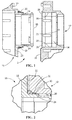
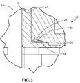
- FIGS. 1 through 3 are sectional views of a connector assembly 2 having a first or plug connector housing 10 and a second or receptacle connector housing 12 with a peripheral wedge seal member 30 positioned on the plug connector housing.
- the first or plug connector housing 10 and the second or receptacle connector housing 12 may be mounted to a panel or substrate or may be free standing.
- the peripheral wedge seal member 30 may be secured to the plug connector housing 10 by known methods, such as, but not limited, to adhesive, mounting members or frictional engagement.
- the peripheral wedge seal member 30 may also be positioned on the receptacle connector and secured thereto by using known methods. Alternatively, the peripheral wedge seal member 30 may not be attached to either the plug connector housing 10 or the receptacle connector housing 12.
- the plug connector housing 10 has terminals (not shown) which extend therethrough to mate with mating terminals (not shown) of the receptacle connector housing 12. As many different types of terminals and mating terminals may be used, a detailed description of such terminals and mating terminals shall not be provided.
- the receptacle connector housing 12 has a plug connector receiving opening 14 which is dimensioned to receive a mating portion 16 of the plug connector housing 10 therein.
- the mating connector receiving opening 14 has side walls 20 which extend from a plug connector engaging wall 18.
- An end wall 21 is provided at the bottom of the opening 14.
- the side walls 20 extend about the periphery of the opening 14.
- the side walls 20 may have linear configurations or may have arcuate surfaces or projections positioned thereon.
- Receptacle contacts (not shown) extend from the end wall 21 into the opening 14.
- the mating portion 16 of the plug connector housing 10 has side walls 24 which extend from a receptacle connector engaging wall 22.
- the side walls 24 extend about the periphery of the mating portion 16 to form the mating portion 16.
- the side walls 24 may have linear configurations or may have arcuate surfaces or projections positioned thereon, such as, but not limited to, latching projections.
- the mating portion 16 has plug contacts (not shown) positioned in the mating portion 16 for electrically engaging the receptacle contacts when the plug connector housing 10 and the receptacle connector housing 12 are mated together.
- the mating portion 16 is dimensioned to be received in the opening 14 and movable therein between an unmated position and a mated position.
- peripheral wedge seal member 30 may be used with plug connector housings 10 and receptacle connector housings 12 of many different configurations and sizes, a more detailed description of such plug connector housings 10 and receptacle connector housings 12 shall not be provided.
- the peripheral wedge seal member 30 is positioned on the side walls 24 of the mating portion 16 of the plug connector housing 10.
- the peripheral wedge seal member 30 is positioned proximate the receptacle connector engaging wall 22.
- the peripheral wedge seal member 30 may be secured to the mating portion 16 of the plug connector housing 10 by known methods, such as, but not limited, to adhesive, mounting members or frictional engagement.
- the plug connector engaging wall 18 of the receptacle connector 12 is moved toward the receptacle connector engaging wall 22 of the plug connector housing 10.
- leading portions 26 of the side walls 20 engage the peripheral wedge seal member 30.
- the peripheral wedge seal member 30 is compressed, thereby providing an effective seal between the side walls 20 of the receptacle connector housing 12 and the side walls 24 of the plug connector housing 10.
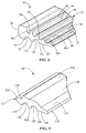
- the peripheral wedge seal member 30 has a deformable body 31 which may be made from any material having the structural integrity and structural flexibility needed. Such material includes, but is not limited to, plastic, rubber or elastomeric.
- the peripheral wedge seal member 30 is a rectangular member with tapered walls 32 which extend from a thicker first surface or end 34 to a less thick second surface or end 36, as best shown in FIG. 6 .
- the walls 32 have first surfaces 38 and second surfaces 40 which extend at an angle or an acute angle relative to the first surfaces 38 to create the taper of the walls 32. While a rectangular member is shown, the peripheral wedge seal member 30 may have other configurations, including, but not limited to, square or round.
- the first surfaces 38 have two recesses or grooves 42 which extend the entire length of each respective wall 32.
- the grooves 42 and support ribs 43 provided there between and/or proximate thereto act as spring members to allow for better compression of the peripheral wedge seal member 30 when the plug connector housing 10 and the receptacle connector housing 12 are mated together. This allows the plug connector housing 10 and the receptacle connector housing 12 to be mated and unmated with reduced force.
- the grooves 42 and ribs 43 provide additional compliancy to the peripheral wedge seal member 30, allowing the peripheral wedge seal member 30 to provide vibration dampening between the plug connector housing 10 and the receptacle connector housing 12.
- the spacing provided between the grooves 42 and the size of the grooves 42 may vary depending upon the insertion forces, compliancy and vibration dampening characteristics desired for the particular connector assembly 2. While two grooves 42 are shown on each side wall 32, other number of grooves may be used without departing from the scope of the invention.
- the second surfaces 40 have four recesses or channels 44 which extend the entire length of each respective wall 32.
- the channels 44 have slightly different configurations depending upon their location on the second surfaces 40.
- channels 44a have bottom surfaces 46a which are positioned further from second surfaces 40 than bottom surfaces 46d of channels 44d.
- Deformable ribs 48 are provided between and/or proximate to the channels 44.
- the ribs 48 have slightly different configurations depending upon their location on the second surfaces 40. For example, ribs 48a are longer than ribs 48c.
- the recesses 44 and the ribs 48 are provided to allow for better compression of the peripheral wedge seal member 30 when the plug connector housing 10 and the receptacle connector housing 12 are mated together. This allows the plug connector housing 10 and the receptacle connector housing 12 to be mated and unmated with reduced force.
- the recesses 44 and the ribs 48 provide additional compliancy to the peripheral wedge seal member 30, allowing the peripheral wedge seal member 30 to provide a proper seal between the plug connector housing 10 and the receptacle connector housing 12 and to provide vibration dampening between the plug connector housing 10 and the receptacle connector housing 12.
- the spacing provided between the recesses 44 and the size of the ribs 48 may vary depending upon the insertion forces, compliancy and vibration dampening characteristics desired for the particular connector assembly 2. While four recesses 44 and three ribs 48 are shown on each side wall 32, other number of recesses and ribs may be used without departing from the scope of the invention.
- the grooves 42, ribs 43, channels 44 and ribs 48 form compliant sections which are able to absorb forces transmitted by the plug connector housing 10, the receptacle connector housing 12 or both.
- the peripheral wedge seal member 130 has a deformable body 131 which may be made from any material having the structural integrity and structural flexibility needed. Such material includes, but is not limited to, plastic, rubber or elastomeric.
- the peripheral wedge seal member 130 is a rectangular member tapered walls 132 which extend from a thicker first surface or end 134 to a less thick second surface or end 136, as best shown in FIG. 9 .
- the walls 132 have first surfaces 138 and second surfaces 140 which extend at an angle or an acute angle relative to the first surfaces 138 to create the taper of the walls 132. While a rectangular member is shown, the peripheral wedge seal member 130 may have other configurations, including, but not limited to, square or round.
- the first surfaces 138 have two recesses or grooves 142 which extend the entire length of each respective wall 132.
- the grooves 142 and support ribs 143 provide there between and/or proximate thereto act as spring members to allow for better compression of the peripheral wedge seal member 130 when the plug connector housing 10 and the receptacle connector housing 12 are mated together. This allows the plug connector housing 10 and the receptacle connector housing 12 to be mated and unmated with reduced force.
- the grooves 142 and ribs 143 provide additional compliancy to the peripheral wedge seal member 130, allowing the peripheral wedge seal member 130 to provide vibration dampening between the plug connector housing 10 and the receptacle connector housing 12.
- the spacing provided between the grooves 142 and the size of the grooves 142 may vary depending upon the insertion forces, compliancy and vibration dampening characteristics desired for the particular connector assembly 2. While two grooves 142 are shown on each side wall 132, other number of grooves may be used without departing from the scope of the invention.
- the second surfaces 140 have recesses 144 which extend the entire length of each respective wall 132.
- the recesses 144 are provided proximate the first end 134 of the walls 132.
- Deformable ribs 148 extend from the second surfaces 140.
- the ribs 148 have curved or arcuate configurations which project from the second surfaces 140.
- the ribs are positioned between the recesses 144 and second ends 136.
- the recesses 144 and the ribs 148 are provided to allow for better compression of the peripheral wedge seal member 130 when the plug connector housing 10 and the receptacle connector housing 12 are mated together. This allows the plug connector housing 10 and the receptacle connector housing 12 to be mated and unmated with reduced force.
- the recesses 144 and the ribs 148 provide additional compliancy to the peripheral wedge seal member 130, allowing the peripheral wedge seal member 130 to provide a proper seal between the plug connector housing 10 and the receptacle connector housing 12 and to provide vibration dampening between the plug connector housing 10 and the receptacle connector housing 12.
- the spacing provided between the recesses 144 and the ribs, the size of the recesses 144 and the size of the ribs 148 may vary depending upon the insertion forces, compliancy and vibration dampening characteristics desired for the particular connector assembly 2. While one recess 144 and one rib 148 are shown on each side wall 132, other number of recesses and ribs may be used without departing from the scope of the invention.
- the grooves 142, ribs 143, channels 144 and ribs 148 form compliant sections which are able to absorb forces transmitted by the plug connector housing 10, the receptacle connector housing 12 or both.
- Peripheral wedge seals according to the present invention provide an effective seal over a wide range of functional housing dimensions, thereby accommodate a greater range of manufacturing tolerances than known seals.
- peripheral wedge seals according to the present invention provide for lower mating and un-mating forces, provide more compliancy and provide sufficient vibration dampening between the plug connector the receptacle connector even in harsh environments.
Landscapes
- Connector Housings Or Holding Contact Members (AREA)
Abstract
Description
- The present invention is directed to a peripheral wedge seal member. In particular, the invention is directed to a peripheral wedge seal member which provides sealing and vibration dampening between a housing of a plug connector and a housing of a receptacle connector.
- An electrical connector assembly includes a first or plug connector and a second or receptacle connector that are configured to mate with one another. Each connector typically has a housing and at least one cavity extends through the housing. Each cavity is configured to receive a terminal fitting. One end of each terminal fitting typically is connected to a conductor, such as the wire, cable, busbar, an electrical device or a conductive region of a circuit board. The opposed end of each terminal fitting is configured for achieving electrical connection with a terminal fitting in the mating connector.
- Many connectors, such as those used in automotive vehicles, will be exposed to harsh environments in which moisture and vibrations can cause the electrical connection between the mating connectors to fail. For example, while the housing of an electrical connector is typically formed from a resin or other material that can withstand periodic exposure to moisture, if the assembly is not properly sealed, moisture can adversely affect the metallic terminal fittings and can cause a shorting between two terminal fittings. A short circuit can have serious effects on critical components of a vehicle, such as warning lights, airbags and the like.
- Many connectors include an elastomeric seal to prevent intrusion of moisture into the region of the connector that contains the terminal fittings and the conductors to which the terminal fittings are connected. A seal of this type typically is mounted at an area where two parts of the mating housings will telescope together. For example, a frame-shaped seal or a toroid-shaped seal may be mounted over one housing of a connector assembly. The end of the mating housing will abut against the seal when the housings are connected. Thus, the seal engages the interface between the two housings to provide sealing.
- However, many of the known seals do not have sufficient structural flexibility to provide proper sealing and vibration dampening for a wide range of dimensions or in a wide range of environments. In addition, mating and un-mating forces associated with known seals makes it difficult to access when service is required.
- Therefore, the problem to be solved is the need to have a peripheral wedge seal which can be used to effectively seal the assembly over a wide range of functional dimensions, provides for lower mating and un-mating forces, provides more compliancy, and provides sufficient vibration dampening between the plug connector and the receptacle connector even in harsh environments.
- The solution is provided by a seal member for use with a plug connector housing and a receptacle connector housing. The seal member includes a deformable body which has tapered walls which extend from a thicker first end to a less thick second end. Each of the walls has a first surface and a second surface which is angled with respect to the first surface. At least one groove extends along the first surface. At least one support rib is provided proximate the at least one groove. The at least one groove and the at least one support rib form a spring member which allows the deformable body of the seal member to compress when the plug connector housing and the receptacle connector housing are mated together. The seal member may be a peripheral or a peripheral wedge seal member. The second surface may be at an acute angle with respect to the first surface. The first surface may be at least part of an inner side of the seal member and the second surface may be at least part of an outer side of the seal member.
- The invention will now be described by way of example with reference to the accompanying drawings in which:
-
FIG. 1 is a cross-sectional view of a plug connector and a receptacle connector prior to being mated together, the plug connector having an illustrative embodiment of the peripheral wedge seal member of the present invention; -
FIG. 2 is a cross-section view of the plug connector and the receptacle connector ofFIG. 1 shown in a partially mated position; -
FIG. 3 is a cross-section view of the plug connector and the receptacle connector ofFIGS. 1 and 2 shown in a fully mated position; -
FIG. 4 is a top perspective view of the illustrative peripheral wedge seal member shown inFIG. 1 ; -
FIG. 5 is a bottom perspective view of the illustrative peripheral wedge seal member shown inFIG. 4 ; -
FIG. 6 is a cross-sectional view of the illustrative peripheral wedge seal member shown inFIG. 4 ; -
FIG. 7 is a top perspective view of an alternate illustrative peripheral wedge seal member; -
FIG. 8 is a bottom perspective view of the illustrative peripheral wedge seal member shown inFIG. 7 ; and -
FIG. 9 is a cross-sectional view of the illustrative peripheral wedge seal member shown inFIG. 7 . - The present invention will be described more fully hereinafter with reference to the accompanying drawings, in which illustrative embodiments of the invention are shown. In the drawings, the relative sizes of regions or features may be exaggerated for clarity. This invention may, however, be embodied in many different forms and should not be construed as limited to the embodiments set forth herein; rather, these embodiments are provided so that this disclosure will be thorough and complete, and will fully convey the scope of the invention to those skilled in the art.
- It will be understood that spatially relative terms, such as "top", "upper", "lower" and the like, may be used herein for ease of description to describe one element's or feature's relationship to another element(s) or feature(s) as illustrated in the figures. It will be understood that the spatially relative terms are intended to encompass different orientations of the device in use or operation in addition to the orientation depicted in the figures. For example, if the device in the figures is turned over, elements described as "over" other elements or features would then be oriented "under" the other elements or features. Thus, the exemplary term "over" can encompass both an orientation of over and under. The device may be otherwise oriented (rotated 90 degrees or at other orientations) and the spatially relative descriptors used herein interpreted accordingly.
- An embodiment is directed to a seal member for use with a plug connector housing and a receptacle connector housing. The seal member includes a deformable body which has tapered walls which extend from a thicker first end to a less thick second end. Each of the walls has a first surface and a second surface which is angled with respect to the first surface. At least one groove extends along the first surface. At least one support rib is provided proximate the at least one groove. The at least one groove and the at least one support rib form a spring member which allows the deformable body of the seal member to compress when the plug connector housing and the receptacle connector housing are mated together.
- An embodiment is directed to a peripheral wedge seal member for use with a plug connector housing and a receptacle connector housing. The peripheral wedge seal member includes a deformable body which has tapered walls which extend from a thicker first end to a less thick second end. Each of the walls has a first surface and a second surface which is angled with respect to the first surfaces. Each of the walls has a compliant section which absorbs forces transmitted by the plug connector housing, the receptacle connector housing or both. Each compliant section has at least one groove extending along the first surface and at least one support rib provided proximate the at least one groove.
- An embodiment is directed to a peripheral wedge seal member for use with a plug connector housing and a receptacle connector housing. The peripheral wedge seal member includes a deformable body which has tapered walls which extend from a thicker first end to a less thick second end. The walls have first surfaces and second surfaces which are angled with respect to the first surfaces. Each of the walls has a compliant section which absorbs forces transmitted by the plug connector housing, the receptacle connector housing or both. Each compliant section has at least one groove extending along the first surface, at least one support rib provided proximate the at least one groove, at least one recess which extends along the second surface and at least one deformable rib which is provided proximate the at least one recess.
-
FIGS. 1 through 3 are sectional views of aconnector assembly 2 having a first orplug connector housing 10 and a second orreceptacle connector housing 12 with a peripheralwedge seal member 30 positioned on the plug connector housing. The first or plug connector housing 10 and the second orreceptacle connector housing 12 may be mounted to a panel or substrate or may be free standing. The peripheralwedge seal member 30 may be secured to theplug connector housing 10 by known methods, such as, but not limited, to adhesive, mounting members or frictional engagement. The peripheralwedge seal member 30 may also be positioned on the receptacle connector and secured thereto by using known methods. Alternatively, the peripheralwedge seal member 30 may not be attached to either theplug connector housing 10 or thereceptacle connector housing 12. - The
plug connector housing 10 has terminals (not shown) which extend therethrough to mate with mating terminals (not shown) of thereceptacle connector housing 12. As many different types of terminals and mating terminals may be used, a detailed description of such terminals and mating terminals shall not be provided. - As shown in
FIG. 1 , thereceptacle connector housing 12 has a plugconnector receiving opening 14 which is dimensioned to receive amating portion 16 of theplug connector housing 10 therein. The matingconnector receiving opening 14 hasside walls 20 which extend from a plugconnector engaging wall 18. Anend wall 21 is provided at the bottom of theopening 14. Theside walls 20 extend about the periphery of theopening 14. Theside walls 20 may have linear configurations or may have arcuate surfaces or projections positioned thereon. Receptacle contacts (not shown) extend from theend wall 21 into theopening 14. - The
mating portion 16 of theplug connector housing 10 hasside walls 24 which extend from a receptacleconnector engaging wall 22. Theside walls 24 extend about the periphery of themating portion 16 to form themating portion 16. Theside walls 24 may have linear configurations or may have arcuate surfaces or projections positioned thereon, such as, but not limited to, latching projections. Themating portion 16 has plug contacts (not shown) positioned in themating portion 16 for electrically engaging the receptacle contacts when theplug connector housing 10 and thereceptacle connector housing 12 are mated together. Themating portion 16 is dimensioned to be received in theopening 14 and movable therein between an unmated position and a mated position. - As the peripheral
wedge seal member 30 may be used withplug connector housings 10 andreceptacle connector housings 12 of many different configurations and sizes, a more detailed description of suchplug connector housings 10 andreceptacle connector housings 12 shall not be provided. - In the illustrative embodiment shown, the peripheral
wedge seal member 30 is positioned on theside walls 24 of themating portion 16 of theplug connector housing 10. The peripheralwedge seal member 30 is positioned proximate the receptacleconnector engaging wall 22. As previously stated, the peripheralwedge seal member 30 may be secured to themating portion 16 of theplug connector housing 10 by known methods, such as, but not limited, to adhesive, mounting members or frictional engagement. - As shown in
FIGS. 1 through 3 , as theplug connector housing 10 and thereceptacle connector housing 12 are moved together, the plugconnector engaging wall 18 of thereceptacle connector 12 is moved toward the receptacleconnector engaging wall 22 of theplug connector housing 10. As theplug connector housing 10 and thereceptacle connector housing 12 are moved from the position shown inFIG. 1 to the position shown inFIG. 2 , leadingportions 26 of theside walls 20 engage the peripheralwedge seal member 30. As theplug connector housing 10 and thereceptacle connector housing 12 are moved from the position shown inFIG. 2 to the fully inserted position shown inFIG. 3 , the peripheralwedge seal member 30 is compressed, thereby providing an effective seal between theside walls 20 of thereceptacle connector housing 12 and theside walls 24 of theplug connector housing 10. - Referring to
FIGS. 4 through 6 , the peripheralwedge seal member 30 has adeformable body 31 which may be made from any material having the structural integrity and structural flexibility needed. Such material includes, but is not limited to, plastic, rubber or elastomeric. In the illustrate embodiment shown, the peripheralwedge seal member 30 is a rectangular member with taperedwalls 32 which extend from a thicker first surface or end 34 to a less thick second surface or end 36, as best shown inFIG. 6 . Thewalls 32 havefirst surfaces 38 andsecond surfaces 40 which extend at an angle or an acute angle relative to thefirst surfaces 38 to create the taper of thewalls 32. While a rectangular member is shown, the peripheralwedge seal member 30 may have other configurations, including, but not limited to, square or round. - In the embodiment shown, the
first surfaces 38 have two recesses orgrooves 42 which extend the entire length of eachrespective wall 32. Thegrooves 42 andsupport ribs 43 provided there between and/or proximate thereto act as spring members to allow for better compression of the peripheralwedge seal member 30 when theplug connector housing 10 and thereceptacle connector housing 12 are mated together. This allows theplug connector housing 10 and thereceptacle connector housing 12 to be mated and unmated with reduced force. In addition, thegrooves 42 andribs 43 provide additional compliancy to the peripheralwedge seal member 30, allowing the peripheralwedge seal member 30 to provide vibration dampening between theplug connector housing 10 and thereceptacle connector housing 12. The spacing provided between thegrooves 42 and the size of thegrooves 42 may vary depending upon the insertion forces, compliancy and vibration dampening characteristics desired for theparticular connector assembly 2. While twogrooves 42 are shown on eachside wall 32, other number of grooves may be used without departing from the scope of the invention. - The second surfaces 40 have four recesses or
channels 44 which extend the entire length of eachrespective wall 32. As thewalls 32 of peripheralwedge seal member 30 are tapered, thechannels 44 have slightly different configurations depending upon their location on the second surfaces 40. For example,channels 44a havebottom surfaces 46a which are positioned further fromsecond surfaces 40 thanbottom surfaces 46d ofchannels 44d.Deformable ribs 48 are provided between and/or proximate to thechannels 44. As thewalls 32 of the peripheralwedge seal member 30 are tapered, theribs 48 have slightly different configurations depending upon their location on the second surfaces 40. For example,ribs 48a are longer thanribs 48c. Therecesses 44 and theribs 48 are provided to allow for better compression of the peripheralwedge seal member 30 when theplug connector housing 10 and thereceptacle connector housing 12 are mated together. This allows theplug connector housing 10 and thereceptacle connector housing 12 to be mated and unmated with reduced force. In addition, therecesses 44 and theribs 48 provide additional compliancy to the peripheralwedge seal member 30, allowing the peripheralwedge seal member 30 to provide a proper seal between theplug connector housing 10 and thereceptacle connector housing 12 and to provide vibration dampening between theplug connector housing 10 and thereceptacle connector housing 12. The spacing provided between therecesses 44 and the size of theribs 48 may vary depending upon the insertion forces, compliancy and vibration dampening characteristics desired for theparticular connector assembly 2. While fourrecesses 44 and threeribs 48 are shown on eachside wall 32, other number of recesses and ribs may be used without departing from the scope of the invention. - The
grooves 42,ribs 43,channels 44 andribs 48 form compliant sections which are able to absorb forces transmitted by theplug connector housing 10, thereceptacle connector housing 12 or both. - Referring to the alternate illustrative embodiment of
FIGS. 7 through 9 , the peripheralwedge seal member 130 has adeformable body 131 which may be made from any material having the structural integrity and structural flexibility needed. Such material includes, but is not limited to, plastic, rubber or elastomeric. In the illustrative embodiment shown, the peripheralwedge seal member 130 is a rectangular member taperedwalls 132 which extend from a thicker first surface or end 134 to a less thick second surface or end 136, as best shown inFIG. 9 . Thewalls 132 havefirst surfaces 138 andsecond surfaces 140 which extend at an angle or an acute angle relative to thefirst surfaces 138 to create the taper of thewalls 132. While a rectangular member is shown, the peripheralwedge seal member 130 may have other configurations, including, but not limited to, square or round. - In the embodiment shown, the
first surfaces 138 have two recesses orgrooves 142 which extend the entire length of eachrespective wall 132. Thegrooves 142 andsupport ribs 143 provide there between and/or proximate thereto act as spring members to allow for better compression of the peripheralwedge seal member 130 when theplug connector housing 10 and thereceptacle connector housing 12 are mated together. This allows theplug connector housing 10 and thereceptacle connector housing 12 to be mated and unmated with reduced force. In addition, thegrooves 142 andribs 143 provide additional compliancy to the peripheralwedge seal member 130, allowing the peripheralwedge seal member 130 to provide vibration dampening between theplug connector housing 10 and thereceptacle connector housing 12. The spacing provided between thegrooves 142 and the size of thegrooves 142 may vary depending upon the insertion forces, compliancy and vibration dampening characteristics desired for theparticular connector assembly 2. While twogrooves 142 are shown on eachside wall 132, other number of grooves may be used without departing from the scope of the invention. - The
second surfaces 140 haverecesses 144 which extend the entire length of eachrespective wall 132. Therecesses 144 are provided proximate thefirst end 134 of thewalls 132.Deformable ribs 148 extend from the second surfaces 140. In the illustrative embodiment shown, theribs 148 have curved or arcuate configurations which project from the second surfaces 140. The ribs are positioned between therecesses 144 and second ends 136. Therecesses 144 and theribs 148 are provided to allow for better compression of the peripheralwedge seal member 130 when theplug connector housing 10 and thereceptacle connector housing 12 are mated together. This allows theplug connector housing 10 and thereceptacle connector housing 12 to be mated and unmated with reduced force. In addition, therecesses 144 and theribs 148 provide additional compliancy to the peripheralwedge seal member 130, allowing the peripheralwedge seal member 130 to provide a proper seal between theplug connector housing 10 and thereceptacle connector housing 12 and to provide vibration dampening between theplug connector housing 10 and thereceptacle connector housing 12. The spacing provided between therecesses 144 and the ribs, the size of therecesses 144 and the size of theribs 148 may vary depending upon the insertion forces, compliancy and vibration dampening characteristics desired for theparticular connector assembly 2. While onerecess 144 and onerib 148 are shown on eachside wall 132, other number of recesses and ribs may be used without departing from the scope of the invention. - The
grooves 142,ribs 143,channels 144 andribs 148 form compliant sections which are able to absorb forces transmitted by theplug connector housing 10, thereceptacle connector housing 12 or both. - Peripheral wedge seals according to the present invention provide an effective seal over a wide range of functional housing dimensions, thereby accommodate a greater range of manufacturing tolerances than known seals. In addition peripheral wedge seals according to the present invention provide for lower mating and un-mating forces, provide more compliancy and provide sufficient vibration dampening between the plug connector the receptacle connector even in harsh environments.
- In addition, as the seals are compressed when the plug connector housing and receptacle connector housing are mated, potential energy is developed and stored in the compliant sections. Consequently, when the plug connector housing and receptacle connector housing are unmated, the release of the compliant section releases the potential energy, thereby facilitating the unmating of the housings.
Claims (12)
- A seal member (30, 130) for use with a plug connector housing (10) and a receptacle connector housing (12), the seal member comprising:a deformable body (31, 131) having at least one tapered wall (32, 132) which extends from a thicker first end (34, 134) to a less thick second end (36, 136), the or each of the walls having a first surface (38, 138) and a second surface (40, 140) which is angled with respect to the first surface; andat least one groove (42, 142) extending along the first surface (38, 138), at least one support rib (43, 143) provided proximate the at least one groove, the at least one groove and the at least one support rib forming a spring member which allows the deformable body (31, 131) of the seal member (30, 130) to compress when the plug connector housing (10) and the receptacle connector housing (12) are mated together.
- The seal member as recited in claim 1, wherein the deformable body (31, 131) is plastic, rubber or elastomeric material.
- The seal member as recited in claim 1 or 2, wherein the seal member is a peripheral wedge seal member (30, 130) with a rectangular configuration.
- The seal member as recited in claim 1, 2 or 3, wherein the deformable body (31, 131) has a plurality of tapered walls (32, 132).
- The seal member as recited in claim 1 or 2, wherein the seal member is a peripheral wedge seal member with a round configuration.
- The seal member as recited in any preceding claim, wherein the at least one groove is two grooves (42, 142) with a support rib (43, 143) provided there between.
- The seal member as recited in any preceding claim, wherein at least one recess (44) extends along the second surface (40).
- The seal member as recited in claim 7, wherein at least one deformable rib (48) is provided proximate the at least one recess (44).
- The seal member as recited in claim 7 or 8, wherein the at least one recess is four recesses (44) which have different configurations depending upon their location on the second surface (40).
- The seal member as recited in claim 7, 8 or 9, wherein the at least one recess (144) is provided proximate the first end (134).
- The seal member as recited in claim 10, wherein at least one deformable rib (148) is provided on the second surface (140) between the at least one recess (144) and the second end (136).
- The seal member as recited in claim 11, wherein at least one deformable rib (148) has a curved or arcuate configuration.
Applications Claiming Priority (1)
| Application Number | Priority Date | Filing Date | Title |
|---|---|---|---|
| US14/788,938 US20170005432A1 (en) | 2015-07-01 | 2015-07-01 | Peripheral wedge seal member |
Publications (1)
| Publication Number | Publication Date |
|---|---|
| EP3113293A1 true EP3113293A1 (en) | 2017-01-04 |
Family
ID=56289386
Family Applications (1)
| Application Number | Title | Priority Date | Filing Date |
|---|---|---|---|
| EP16176733.0A Withdrawn EP3113293A1 (en) | 2015-07-01 | 2016-06-28 | Peripheral wedge seal member |
Country Status (2)
| Country | Link |
|---|---|
| US (1) | US20170005432A1 (en) |
| EP (1) | EP3113293A1 (en) |
Cited By (2)
| Publication number | Priority date | Publication date | Assignee | Title |
|---|---|---|---|---|
| CN110148860A (en) * | 2019-05-29 | 2019-08-20 | 天长市富达电子有限公司 | A kind of novel power-line plug with water-proof function |
| CN110998980A (en) * | 2017-08-01 | 2020-04-10 | 德尔福技术有限公司 | Connector assembly and seal |
Families Citing this family (1)
| Publication number | Priority date | Publication date | Assignee | Title |
|---|---|---|---|---|
| JP2017208193A (en) * | 2016-05-17 | 2017-11-24 | 日本圧着端子製造株式会社 | Waterproof connector |
Citations (3)
| Publication number | Priority date | Publication date | Assignee | Title |
|---|---|---|---|---|
| EP0655802A1 (en) * | 1993-11-25 | 1995-05-31 | Sumitomo Wiring Systems, Ltd. | Sealing structure for panel-mounted electrical connector |
| US5622512A (en) * | 1994-04-15 | 1997-04-22 | Yazaki Corporation | Apparatus for forming waterproof connection |
| WO2014104122A1 (en) * | 2012-12-27 | 2014-07-03 | 住友電装株式会社 | Waterproof container |
-
2015
- 2015-07-01 US US14/788,938 patent/US20170005432A1/en not_active Abandoned
-
2016
- 2016-06-28 EP EP16176733.0A patent/EP3113293A1/en not_active Withdrawn
Patent Citations (3)
| Publication number | Priority date | Publication date | Assignee | Title |
|---|---|---|---|---|
| EP0655802A1 (en) * | 1993-11-25 | 1995-05-31 | Sumitomo Wiring Systems, Ltd. | Sealing structure for panel-mounted electrical connector |
| US5622512A (en) * | 1994-04-15 | 1997-04-22 | Yazaki Corporation | Apparatus for forming waterproof connection |
| WO2014104122A1 (en) * | 2012-12-27 | 2014-07-03 | 住友電装株式会社 | Waterproof container |
Cited By (3)
| Publication number | Priority date | Publication date | Assignee | Title |
|---|---|---|---|---|
| CN110998980A (en) * | 2017-08-01 | 2020-04-10 | 德尔福技术有限公司 | Connector assembly and seal |
| CN110998980B (en) * | 2017-08-01 | 2021-04-09 | 德尔福技术有限公司 | Connector assembly and seal |
| CN110148860A (en) * | 2019-05-29 | 2019-08-20 | 天长市富达电子有限公司 | A kind of novel power-line plug with water-proof function |
Also Published As
| Publication number | Publication date |
|---|---|
| US20170005432A1 (en) | 2017-01-05 |
Similar Documents
| Publication | Publication Date | Title |
|---|---|---|
| JP5876510B2 (en) | Electrical connector and connector system | |
| US9847597B2 (en) | Electrical connector with sealing structure | |
| KR102181424B1 (en) | Right angle header assembly | |
| US7892025B2 (en) | Sealed connector assembly | |
| CN108988006B (en) | Connector mounting structure and terminal block | |
| KR101031898B1 (en) | Connector, jack component, electronic equipment and plug component | |
| US9577373B2 (en) | Electric connector | |
| EP2200130A1 (en) | Shielded electrical plug-in connector | |
| JP4976560B2 (en) | Electrical connector with sealing mat | |
| KR101701587B1 (en) | Insulating body of a plug connector | |
| US9209553B2 (en) | Plug-connector housing and plug connector | |
| US10367293B1 (en) | Electrical connector | |
| EP3113293A1 (en) | Peripheral wedge seal member | |
| US20030032321A1 (en) | Sealed connector | |
| EP3346557B1 (en) | Waterproof structure for connector | |
| CN110391532B (en) | Connector with a locking member | |
| US10008803B2 (en) | Connector for a camera with reduced dimensions in a fitting direction | |
| EP2866305A1 (en) | Connector | |
| CN113196578B (en) | Plug-in connector part for making contact in several spatial directions | |
| JP6290407B2 (en) | Connector device between electrical device or electronic device and connector connection unit, and use of connector device | |
| EP3675286A1 (en) | Connector | |
| KR102249090B1 (en) | Mounting frame with PE-contact | |
| US10971829B2 (en) | Connector and package body | |
| US10128605B2 (en) | Connector | |
| CN105811159B (en) | Plug connector part with a line insertion device |
Legal Events
| Date | Code | Title | Description |
|---|---|---|---|
| PUAI | Public reference made under article 153(3) epc to a published international application that has entered the european phase |
Free format text: ORIGINAL CODE: 0009012 |
|
| AK | Designated contracting states |
Kind code of ref document: A1 Designated state(s): AL AT BE BG CH CY CZ DE DK EE ES FI FR GB GR HR HU IE IS IT LI LT LU LV MC MK MT NL NO PL PT RO RS SE SI SK SM TR |
|
| AX | Request for extension of the european patent |
Extension state: BA ME |
|
| RAP1 | Party data changed (applicant data changed or rights of an application transferred) |
Owner name: TE CONNECTIVITY CORPORATION |
|
| 17P | Request for examination filed |
Effective date: 20170626 |
|
| RBV | Designated contracting states (corrected) |
Designated state(s): AL AT BE BG CH CY CZ DE DK EE ES FI FR GB GR HR HU IE IS IT LI LT LU LV MC MK MT NL NO PL PT RO RS SE SI SK SM TR |
|
| 17Q | First examination report despatched |
Effective date: 20170929 |
|
| STAA | Information on the status of an ep patent application or granted ep patent |
Free format text: STATUS: THE APPLICATION IS DEEMED TO BE WITHDRAWN |
|
| 18D | Application deemed to be withdrawn |
Effective date: 20190424 |