EP3109080B1 - Sunshade assembly and open roof construction provided therewith - Google Patents
Sunshade assembly and open roof construction provided therewith Download PDFInfo
- Publication number
- EP3109080B1 EP3109080B1 EP15173180.9A EP15173180A EP3109080B1 EP 3109080 B1 EP3109080 B1 EP 3109080B1 EP 15173180 A EP15173180 A EP 15173180A EP 3109080 B1 EP3109080 B1 EP 3109080B1
- Authority
- EP
- European Patent Office
- Prior art keywords
- sunscreen
- wing
- positioning member
- sunshade assembly
- flap
- Prior art date
- Legal status (The legal status is an assumption and is not a legal conclusion. Google has not performed a legal analysis and makes no representation as to the accuracy of the status listed.)
- Active
Links
Images


Classifications
-
- B—PERFORMING OPERATIONS; TRANSPORTING
- B60—VEHICLES IN GENERAL
- B60J—WINDOWS, WINDSCREENS, NON-FIXED ROOFS, DOORS, OR SIMILAR DEVICES FOR VEHICLES; REMOVABLE EXTERNAL PROTECTIVE COVERINGS SPECIALLY ADAPTED FOR VEHICLES
- B60J7/00—Non-fixed roofs; Roofs with movable panels, e.g. rotary sunroofs
- B60J7/0007—Non-fixed roofs; Roofs with movable panels, e.g. rotary sunroofs moveable head-liners, screens, curtains or blinds for ceilings
- B60J7/0015—Non-fixed roofs; Roofs with movable panels, e.g. rotary sunroofs moveable head-liners, screens, curtains or blinds for ceilings roller blind
-
- B—PERFORMING OPERATIONS; TRANSPORTING
- B60—VEHICLES IN GENERAL
- B60J—WINDOWS, WINDSCREENS, NON-FIXED ROOFS, DOORS, OR SIMILAR DEVICES FOR VEHICLES; REMOVABLE EXTERNAL PROTECTIVE COVERINGS SPECIALLY ADAPTED FOR VEHICLES
- B60J7/00—Non-fixed roofs; Roofs with movable panels, e.g. rotary sunroofs
- B60J7/0007—Non-fixed roofs; Roofs with movable panels, e.g. rotary sunroofs moveable head-liners, screens, curtains or blinds for ceilings
- B60J7/0023—Non-fixed roofs; Roofs with movable panels, e.g. rotary sunroofs moveable head-liners, screens, curtains or blinds for ceilings flexible and foldable
Definitions
- the invention relates to a sunshade assembly according to the preamble of claim 1.
- sunshade assemblies are vehicles which are provided with open roof constructions having roof assemblies.
- Such sunshade assemblies may be integrated into such roof assemblies of open roof constructions during the construction of the vehicles, but also may be provided afterwards (in which case the vehicles are retro-fitted with a so-called after market open roof construction).
- the operating beam is provided with a positioning member which engages between the wing and the sunshade and is longitudinally locked with respect to the wing so that the positioning member may force the sunscreen in outward and in longitudinal directions.
- the positioning member is arranged on a side of the sunscreen opposite to the wing.
- a sunshade assembly comprises the features according to the characterizing portion of claim 1.
- the wing accessible to the positioning member it is possible to allow them to engage so that the positioning member may act on the sunscreen through the wing. In this way, the position of the wing and of the positioning member with respect to the sunscreen is of no concern.
- the wing is made accessible to the respective positioning member by separating each wing from the remainder of the sunscreen near the transversal edge of the sunscreen adjacent the operating beam so that each positioning member is engaged with the respective wing without an interfering sunscreen.
- One possibility thereof is to extend the wing beyond the respective transversal edge of the sunscreen into a protruding flap which is folded to be engaged with the positioning member.
- Extending the wing beyond the transversal edge of the sunscreen makes the accessibility of the wing independent on the position of the wing and the positioning member with respect to the sunscreen as the flap may be folded towards the side of the sunscreen facing away from the wing.
- the protruding flap may be folded back and attached to one of itself and the surface of the sunscreen, the positioning member engaging the flap where it is attached, for example by means of legs straddling the position of attachment.
- the flap can remain protruding from the sunscreen so that the sunscreen cannot interfere with the attachment of the positioning member to (the flap of) the wing anyhow.
- the flap is folded inwardly sideways and wherein overlapping portions of the flap are attached to each other and parts of the positioning members straddle the position of attachment.
- the flap does not have to be folded back but can also be folded sideways as long as there are overlapping parts which can be attached to each other to form a point of engagement for the positioning member.
- the flap is folded inwardly such that the folded flap portion extends substantially in transversal direction of the sunshade.
- each wing is made accessible by means of at least one hole in the sunscreen adjacent the respective wing, and wherein at least a protruding part of the positioning member is inserted through the at least one hole towards the respective wing.
- the wing is not separated from the sunscreen, but is locally made accessible by means of one or more holes through which the positioning member can be inserted to be engaged with the wing.
- the at least one hole may be substantially slot-shaped so as to provide access to a flat protruding part of the positioning member.
- the wing and the portion of the sunscreen that is overlapped by the sunscreen may be attached to each other on one or both sides of the at least one hole.
- This provides a point of engagement in both longitudinal directions for the positioning member.
- the positioning member may comprise a plurality of spaced apart, substantially parallel protruding parts inserted into a corresponding number of holes in the sunscreen.
- Attachment of the wing to itself or the sunscreen is done by stitching. This is an easy way to accomplish the attachment.
- the invention secondly relates to an open roof construction or roof assembly kit for a vehicle having an opening in a stationary roof.
- the kit comprises a movable closure panel configured for opening and closing said roof opening and a sunshade assembly having one or more features herein described.
- FIG. 1 an open roof construction having a roof assembly for a vehicle (schematically represented by a stationary roof 2) is illustrated schematically.
- Said roof assembly is for opening and closing a roof opening 1 in a stationary roof part 2 of the vehicle and includes a movable closure, in this case a panel 3 which, by means not illustrated in detail but known per se, can be moved for opening and closing said roof opening 1.
- the movable panel 3 is guided in longitudinal guides mounted in or formed in the stationary roof part 2 along longitudinal sides 12 of the roof opening 1.
- a user operated device such as a motor or crank (not illustrated) is operably coupled to the panel 3 via cables or the like to move the panel 3 selectively between its open and closed positions.
- the closure panel 3 has been illustrated in a position in which it opens the roof opening 1.
- said sunshade assembly comprises a flexible sunscreen 4, a rotatable winding shaft 5 for winding and unwinding the sunscreen 4 at a first transversal edge and two opposite longitudinal guides 6 and 7.
- the guides 6, 7 can be connected to or formed integral from a single unitary body with the guides of the closure panel (not illustrated).
- the guides 6, 7 can be separate from the guides of the panel, in which case the open roof construction comprises a kit, the minimum of which does further include the panel 3 besides the sunshade assembly.
- Drive members may be provided, which in Fig. 1 have been illustrated schematically by dotted lines 9, 10.
- the drive members may comprise longitudinal members, such as drive cables, driven by an actuator 11, such as an electric motor, for a reciprocating movement for winding and unwinding the sunscreen 4.
- Each drive member 9, 10 is connected on its end within the guide to an operating beam 8 provided at and connected to a transversal edge of the sunscreen 4 remote from the winding shaft 5.
- the reciprocating movement of the sunscreen 4 primarily is generated by the reciprocating movement of the drive members 9 and 10 as caused by the actuator 11, it is possible too that in addition the winding shaft 5 is preloaded in a sense for winding the sunscreen 4 thereon. Further it should be noted that the movement of the sunscreen 4 also may be initiated manually.
- FIG. 2 schematically illustrates a transverse cross section according to II-II in Fig. 1 (it is noted that only the left half of the cross section is shown, the right half being a mirror image thereof).
- Fig. 2 shows the panel 3, right guide 7 (attached to the stationary roof part 2) and operating beam 8.
- the sunscreen 4 is attached to the operating beam 8 in a manner known and not further elucidated here.
- the guide 7 comprises an upper guide channel 13 and a lower guide channel 14.
- the operating beam 8 has attached to its outer end a mounting part 15 which protrudes into the upper guide channel 13 and which is connected therein to drive member 10.
- the operating beam 8 comprises opposite lateral ends each extending into a corresponding upper guide channel 13 and being guided therein, i.e. mounting part 15 engages guide 13 so as to be guided thereby, the guide 13 of which may or may not comprise a channel.
- the corresponding longitudinal edge of the sunscreen 4 will be guided in the lower guide channel 14.
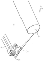
- FIG. 3 part of the operating beam 8 near its right end is shown.
- a positioning member 16 is attached to the operating beam 8.
- the guide 7 with mounting member 15, upper guide channel 13 and lower guide channel 14 have been omitted in this view to more clearly show the positioning member or lip 16.
- the positioning member 16 can be attached to the operating beam 8 through a snap connection (not shown). Thus a releasable connection between the operating beam 8 and positioning member 16 can be created (e.g. for making assembly/disassembly of these parts, and thus the sunshade assembly, easier).
- the positioning member 16 can be integral with the operating beam 8 being formed from a single unitary body.
- Positioning member 16 extends into, and is guided by, lower guide channel 14 ( Fig. 2 ).
- a wing 17 of the sunscreen 4 is unfolded when the sunscreen 4 is wound onto the winding shaft 5 ( Fig. 3 ) and is folded when it is positioned within the guide 7 ( Fig. 2 ).
- This wing 17 may be an integral part (transverse prolongation such as being formed from a single unitary body) of the sunscreen 4 or may be a separate part attached to the sunscreen 4 in any appropriate manner (e.g. stitching, gluing etc.).
- the wing 17 has been folded downwardly, i.e. in a direction away from the side of the sunscreen where the positioning member 16 is situated, that is above the sunscreen 4.
- the positioning member 16 is used to initiate the folding movement of the wing 17 and the wing is therefore engaged with the positioning member 16 in a folded position.
- a longitudinal edge thereof comes out of the lower guide channel 14
- the position thereof can be restored by fully opening the sunscreen (winding it onto the winding shaft 5) and again moving it to a (partially) closed position.
- the wing 17 extending around the lip 16 will take care of again positioning the longitudinal edge of the sunscreen into the corresponding lower guide channel 14.
- positioning member 16 is above the sunscreen 4 and the wing 17 is folded below the sunscreen 4, special measures have been taken to enable an engagement of positioning member 16 and wing 17.
- Figs. 4a, 4b show a first embodiment for the engagement between positioning member 16 and wing 17.
- wing 17 has been extended beyond the transversal edge of sunscreen 4 at the position of operating beam 8 to form a protruding flap 18.
- This transversal edge of sunscreen 4 may be locally displaced by a cut-out in sunscreen 4 so that flap 18 protrudes at a suitable position (not shown here).
- the flap 18 has been folded back to such an extent that it is overlapping sunscreen 4 and is attached, in this case stitched, to the sunscreen 4 with a transversal stitch 20.
- the positioning member 16 is a flat lip having a notch 21 to form two legs 22, 23 which can be straddled to the stitch 20. In this manner, the positioning member 16 can push the edge of sunscreen 4 outwardly and can exert forces to the sunscreen in two longitudinal directions.
- Figs. 5a, 5b show a slightly changed embodiment in which flap 18 is folded and stitched onto itself.
- the positioning member engages flap 18 of wing 17 in front of sunshade 4.
- flap 18 creates only two layers, whereas in the fig. 4 embodiment there are three layers at the position of flap 18: flap 18, sunscreen 4 and wing 17.
- This package of three layers and positioning member 16 could create height problems in guide 7.
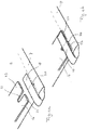
- Figs. 6a, 6b show another embodiment in which flap 18 is not folded back, but sideways in inward direction, so that both flap portions make an angle different from 180 degrees, in this case 90 degrees.
- a stitch 20 is made at the 45 degrees edge, and notch 21 in positioning member 16 is shaped such that legs 22, 23 are positioned in the fold of wing 17 and fit with stitch 20.
- stitch 20 is made in longitudinal direction and notch 21 and legs 22, 23 are adapted accordingly to cooperate with this stich 20. It is of course also possible to use both stitches 20 of Figs. 6 and 7 or make any other kind of attachment.
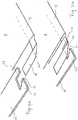
- Figs. 8a, 8b show a different embodiment in that there is no extension of wing 17 to make it accessible for positioning member 16, but there is made an hole 24 (here an elongated slot or slit) in sunscreen 4 adapted to allow positioning member 16 to be inserted into and through this hole 24 to engage wing 17.
- an hole 24 here an elongated slot or slit
- the positioning member 16 is of a size in longitudinal direction which is slightly larger than hole 24 to keep positioning member 16 in hole 20 and to allow positioning member to exert outward forces onto the fold between wing 17 and sunscreen 4. Stitches may be used to strengthen hole 24 in longitudinal direction.
- the Figs. 9a, 9b embodiment comprise two holes 24 to allow legs 22, 23 of positioning member 16 (shaped as in Fig. 4 ) to enter holes 24.
- Several stitches 20 may be used to strengthen holes 24 and allow positioning member to exert forces without the risk of tearing holes 24.
- Figs. 10a, 10b and 11 show still another embodiment including one hole 24 in sunscreen 4, but with a positioning member 16 having three legs, a centre leg 25 entering hole 24 while legs 22 and 23 remain above sunscreen 4 to straddle stitches 20 on opposite sides of sunscreen 4.
- the wing of the sunscreen may be unfolded when wound on the winding shaft, but may also be wound in its folded position.
Landscapes
- Engineering & Computer Science (AREA)
- Mechanical Engineering (AREA)
- Tents Or Canopies (AREA)
- Operating, Guiding And Securing Of Roll- Type Closing Members (AREA)
Description
- The invention relates to a sunshade assembly according to the preamble of
claim 1. - One important field of application of such sunshade assemblies are vehicles which are provided with open roof constructions having roof assemblies. Such sunshade assemblies may be integrated into such roof assemblies of open roof constructions during the construction of the vehicles, but also may be provided afterwards (in which case the vehicles are retro-fitted with a so-called after market open roof construction).
- In
EP 2 151 339 A1claim 1, the operating beam is provided with a positioning member which engages between the wing and the sunshade and is longitudinally locked with respect to the wing so that the positioning member may force the sunscreen in outward and in longitudinal directions. A problem may occur if the positioning member is arranged on a side of the sunscreen opposite to the wing. - In accordance with an aspect of the present invention a sunshade assembly comprises the features according to the characterizing portion of
claim 1. - By making the wing accessible to the positioning member it is possible to allow them to engage so that the positioning member may act on the sunscreen through the wing. In this way, the position of the wing and of the positioning member with respect to the sunscreen is of no concern.
- In a first embodiment, the wing is made accessible to the respective positioning member by separating each wing from the remainder of the sunscreen near the transversal edge of the sunscreen adjacent the operating beam so that each positioning member is engaged with the respective wing without an interfering sunscreen.
- One possibility thereof is to extend the wing beyond the respective transversal edge of the sunscreen into a protruding flap which is folded to be engaged with the positioning member.
- Extending the wing beyond the transversal edge of the sunscreen makes the accessibility of the wing independent on the position of the wing and the positioning member with respect to the sunscreen as the flap may be folded towards the side of the sunscreen facing away from the wing.
- The protruding flap may be folded back and attached to one of itself and the surface of the sunscreen, the positioning member engaging the flap where it is attached, for example by means of legs straddling the position of attachment.
- If the flap is folded onto itself and attached to itself, the flap can remain protruding from the sunscreen so that the sunscreen cannot interfere with the attachment of the positioning member to (the flap of) the wing anyhow.
- It is conceivable that the flap is folded inwardly sideways and wherein overlapping portions of the flap are attached to each other and parts of the positioning members straddle the position of attachment.
- Thus the flap does not have to be folded back but can also be folded sideways as long as there are overlapping parts which can be attached to each other to form a point of engagement for the positioning member.
- Preferably, the flap is folded inwardly such that the folded flap portion extends substantially in transversal direction of the sunshade.
- In another embodiment, each wing is made accessible by means of at least one hole in the sunscreen adjacent the respective wing, and wherein at least a protruding part of the positioning member is inserted through the at least one hole towards the respective wing.
- In this case the wing is not separated from the sunscreen, but is locally made accessible by means of one or more holes through which the positioning member can be inserted to be engaged with the wing.
- The at least one hole may be substantially slot-shaped so as to provide access to a flat protruding part of the positioning member.
- The wing and the portion of the sunscreen that is overlapped by the sunscreen may be attached to each other on one or both sides of the at least one hole.
- This provides a point of engagement in both longitudinal directions for the positioning member.
- The positioning member may comprise a plurality of spaced apart, substantially parallel protruding parts inserted into a corresponding number of holes in the sunscreen.
- Attachment of the wing to itself or the sunscreen is done by stitching. This is an easy way to accomplish the attachment.
- The invention secondly relates to an open roof construction or roof assembly kit for a vehicle having an opening in a stationary roof. The kit comprises a movable closure panel configured for opening and closing said roof opening and a sunshade assembly having one or more features herein described.
- Hereinafter the invention will be elucidated while referring to the drawing, in which:
-
Fig. 1 shows, schematically and in a perspective view, a sunshade assembly applied to an open roof construction; -
Fig. 2 shows, schematically and in a transverse cross section, a detail of the sunshade assembly; -
Fig. 3 shows, schematically and in a perspective view, a part of the sunshade assembly for illustrating its operation; -
Fig. 4a ,b - 10a ,b show, schematically and in a perspective view, embodiments of the engagement of the positioning member and wing of the sunscreen. -
Fig. 11 is a cross section along line XI-XI inFig. 10b . - Firstly referring to
Fig. 1 , an open roof construction having a roof assembly for a vehicle (schematically represented by a stationary roof 2) is illustrated schematically. Said roof assembly is for opening and closing a roof opening 1 in astationary roof part 2 of the vehicle and includes a movable closure, in this case apanel 3 which, by means not illustrated in detail but known per se, can be moved for opening and closing said roof opening 1. Commonly, as is known, themovable panel 3 is guided in longitudinal guides mounted in or formed in thestationary roof part 2 alonglongitudinal sides 12 of theroof opening 1. A user operated device such as a motor or crank (not illustrated) is operably coupled to thepanel 3 via cables or the like to move thepanel 3 selectively between its open and closed positions. InFig. 1 theclosure panel 3 has been illustrated in a position in which it opens theroof opening 1. - Below the roof opening 1 a sunshade assembly is positioned. Basically, said sunshade assembly comprises a
flexible sunscreen 4, a rotatable winding shaft 5 for winding and unwinding thesunscreen 4 at a first transversal edge and two oppositelongitudinal guides 6 and 7. Theguides 6, 7 can be connected to or formed integral from a single unitary body with the guides of the closure panel (not illustrated). Likewise, theguides 6, 7 can be separate from the guides of the panel, in which case the open roof construction comprises a kit, the minimum of which does further include thepanel 3 besides the sunshade assembly. Drive members may be provided, which inFig. 1 have been illustrated schematically bydotted lines 9, 10. As is known per se, the drive members may comprise longitudinal members, such as drive cables, driven by anactuator 11, such as an electric motor, for a reciprocating movement for winding and unwinding thesunscreen 4. - Each
drive member 9, 10 is connected on its end within the guide to anoperating beam 8 provided at and connected to a transversal edge of thesunscreen 4 remote from the winding shaft 5. - Although the reciprocating movement of the
sunscreen 4 primarily is generated by the reciprocating movement of thedrive members 9 and 10 as caused by theactuator 11, it is possible too that in addition the winding shaft 5 is preloaded in a sense for winding thesunscreen 4 thereon. Further it should be noted that the movement of thesunscreen 4 also may be initiated manually. - Now, reference is made to
Fig. 2 which schematically illustrates a transverse cross section according to II-II inFig. 1 (it is noted that only the left half of the cross section is shown, the right half being a mirror image thereof). -
Fig. 2 shows thepanel 3, right guide 7 (attached to the stationary roof part 2) andoperating beam 8. Thesunscreen 4 is attached to theoperating beam 8 in a manner known and not further elucidated here. - The
guide 7 comprises anupper guide channel 13 and alower guide channel 14. Theoperating beam 8 has attached to its outer end a mountingpart 15 which protrudes into theupper guide channel 13 and which is connected therein to drive member 10. Thus, theoperating beam 8 comprises opposite lateral ends each extending into a correspondingupper guide channel 13 and being guided therein, i.e. mountingpart 15 engagesguide 13 so as to be guided thereby, theguide 13 of which may or may not comprise a channel. - The corresponding longitudinal edge of the
sunscreen 4 will be guided in thelower guide channel 14. - Referring to
Fig. 3 , part of theoperating beam 8 near its right end is shown. Apositioning member 16 is attached to theoperating beam 8. Theguide 7 with mountingmember 15,upper guide channel 13 andlower guide channel 14 have been omitted in this view to more clearly show the positioning member orlip 16. - The
positioning member 16 can be attached to theoperating beam 8 through a snap connection (not shown). Thus a releasable connection between theoperating beam 8 and positioningmember 16 can be created (e.g. for making assembly/disassembly of these parts, and thus the sunshade assembly, easier). However, in another embodiment, thepositioning member 16 can be integral with theoperating beam 8 being formed from a single unitary body. - Positioning
member 16 extends into, and is guided by, lower guide channel 14 (Fig. 2 ). Awing 17 of thesunscreen 4 is unfolded when thesunscreen 4 is wound onto the winding shaft 5 (Fig. 3 ) and is folded when it is positioned within the guide 7 (Fig. 2 ). Thiswing 17 may be an integral part (transverse prolongation such as being formed from a single unitary body) of thesunscreen 4 or may be a separate part attached to thesunscreen 4 in any appropriate manner (e.g. stitching, gluing etc.). - In the illustrated embodiment, the
wing 17 has been folded downwardly, i.e. in a direction away from the side of the sunscreen where thepositioning member 16 is situated, that is above thesunscreen 4. The positioningmember 16 is used to initiate the folding movement of thewing 17 and the wing is therefore engaged with the positioningmember 16 in a folded position. When, in a fully or partially closed position of the sunscreen 4 a longitudinal edge thereof comes out of thelower guide channel 14, the position thereof can be restored by fully opening the sunscreen (winding it onto the winding shaft 5) and again moving it to a (partially) closed position. Thewing 17 extending around thelip 16 will take care of again positioning the longitudinal edge of the sunscreen into the correspondinglower guide channel 14. - However, as in the illustrated embodiment the positioning
member 16 is above thesunscreen 4 and thewing 17 is folded below thesunscreen 4, special measures have been taken to enable an engagement ofpositioning member 16 andwing 17. -
Figs. 4a, 4b show a first embodiment for the engagement betweenpositioning member 16 andwing 17. In this case,wing 17 has been extended beyond the transversal edge ofsunscreen 4 at the position ofoperating beam 8 to form a protrudingflap 18. This transversal edge ofsunscreen 4 may be locally displaced by a cut-out insunscreen 4 so thatflap 18 protrudes at a suitable position (not shown here). Theflap 18 has been folded back to such an extent that it is overlappingsunscreen 4 and is attached, in this case stitched, to thesunscreen 4 with atransversal stitch 20. The positioningmember 16 is a flat lip having anotch 21 to form twolegs stitch 20. In this manner, the positioningmember 16 can push the edge ofsunscreen 4 outwardly and can exert forces to the sunscreen in two longitudinal directions. -
Figs. 5a, 5b show a slightly changed embodiment in whichflap 18 is folded and stitched onto itself. The positioning member engagesflap 18 ofwing 17 in front ofsunshade 4. However, due to the rigidity of thewing 17 andflap 18, it is still possible to exert an outwardly directed force ontoflap 18 andsunscreen 4. In this embodiment,flap 18 creates only two layers, whereas in thefig. 4 embodiment there are three layers at the position of flap 18:flap 18,sunscreen 4 andwing 17. This package of three layers and positioningmember 16 could create height problems inguide 7. -
Figs. 6a, 6b show another embodiment in whichflap 18 is not folded back, but sideways in inward direction, so that both flap portions make an angle different from 180 degrees, in this case 90 degrees. Astitch 20 is made at the 45 degrees edge, and notch 21 in positioningmember 16 is shaped such thatlegs wing 17 and fit withstitch 20. - In the
Figs. 7a, 7b embodiment, stitch 20 is made in longitudinal direction and notch 21 andlegs stich 20. It is of course also possible to use bothstitches 20 ofFigs. 6 and7 or make any other kind of attachment. -
Figs. 8a, 8b show a different embodiment in that there is no extension ofwing 17 to make it accessible for positioningmember 16, but there is made an hole 24 (here an elongated slot or slit) insunscreen 4 adapted to allow positioningmember 16 to be inserted into and through thishole 24 to engagewing 17. In this embodiment, there is asingle hole 24 and the positioningmember 16 is of a size in longitudinal direction which is slightly larger thanhole 24 to keep positioningmember 16 inhole 20 and to allow positioning member to exert outward forces onto the fold betweenwing 17 andsunscreen 4. Stitches may be used to strengthenhole 24 in longitudinal direction. - The
Figs. 9a, 9b embodiment comprise twoholes 24 to allowlegs Fig. 4 ) to enterholes 24.Several stitches 20 may be used to strengthenholes 24 and allow positioning member to exert forces without the risk of tearingholes 24. -
Figs. 10a, 10b and 11 show still another embodiment including onehole 24 insunscreen 4, but with a positioningmember 16 having three legs, acentre leg 25 enteringhole 24 whilelegs sunscreen 4 to straddlestitches 20 on opposite sides ofsunscreen 4. - Although the subject matter has been described in a language specific to structural features, it is to be understood that the subject matter defined in the appended claims is not necessarily limited to the specific features described above. Rather, the specific features and acts described above are disclosed as example forms of implementing the claims. For example, the wing of the sunscreen may be unfolded when wound on the winding shaft, but may also be wound in its folded position.
Claims (12)
- A sunshade assembly comprising:a flexible sunscreen (4) having opposed longitudinal edges and opposed transversal edges;two opposed longitudinal guides (6, 7) for receiving therein and guiding corresponding ones of the opposed longitudinal edges of the sunscreen;a rotatable winding shaft (5) configured for winding and unwinding the sunscreen at a first one of its transversal edges;an operating beam (8) connected to the second one of the transversal edges of the sunscreen;two drive cables (9, 10) connected to opposite ends of the operating beam and guided in the opposed longitudinal guides in order to wind and unwind the flexible sunscreen;two positioning members (16) movable together with the operating beam (8), wherein each positioning member extends into a corresponding one of said opposed longitudinal guides (6, 7), and wherein each of the opposed longitudinal edges of the sunscreen (4) at least near the second one of the transversal edges is provided with a wing (17) engaged by the respective positioning member (16),characterized in that each wing is folded inwards in a direction away from the respective positioning member (16), so that the wing (17) and the positioning members (16) are on opposite sides of the sunscreen (4);wherein each wing (17) is made accessible to the respective positioning member (16) from the opposite side of the flexible sunscreen (4) in order to engage it.
- The sunshade assembly of claim 1, wherein the wing (17) is made accessible to the respective positioning member (16) by separating each wing from the remainder of the sunscreen (4) near the transversal edge of the sunscreen adjacent the operating beam (8) so that each positioning member is engaged with the respective wing without an interfering sunscreen.
- The sunshade assembly of claim 2, wherein the wing (17) is extended beyond the respective transversal edge of the sunscreen (4) into a protruding flap (18) which is folded to be engaged with the positioning member (16).
- The sunshade assembly of claim 3, wherein the protruding flap (18) is folded back and attached to one of itself and the surface of the sunscreen (4), the positioning member (16) engaging the flap where it is attached, for example by means of legs (22, 23) straddling the position of attachment.
- The sunshade assembly of claim 3, wherein the flap (18) is folded inwardly sideways and wherein overlapping portions of the flap are attached to each other and parts of the positioning members (16) straddle the position of attachment.
- The sunshade assembly of claim 5, wherein the flap (18) is folded inwardly such that the folded flap portion extends substantially in transversal direction of the sunscreen (4).
- The sunshade assembly according to claim 1, wherein each wing (17) is made accessible by means of at least one hole (24) in the sunscreen (4) adjacent the respective wing, and wherein at least a protruding part of the positioning member (16) is inserted through the at least one hole towards the respective wing.
- The sunshade assembly of claim 7, wherein the at least one hole (24) is substantially slot-shaped.
- The sunshade assembly of claim 7 or 8, wherein the wing (17) and the portion of the sunscreen (4)that is overlapped by the sunscreen are attached to each other on one or both sides of the at least one hole (24).
- The sunshade assembly of any of claims 7 - 9, wherein the positioning member (16) comprises a plurality of spaced apart, substantially parallel protruding parts (22, 23; 25) inserted into a corresponding number of holes (24) in the sunscreen.
- The sunshade assembly of any of claims 4 - 10, wherein attachment of the wing (17) to itself or the sunscreen (4) is done by stitching.
- Open roof construction comprising the sunshade assembly according to any one of the preceding claims.
Priority Applications (3)
| Application Number | Priority Date | Filing Date | Title |
|---|---|---|---|
| EP15173180.9A EP3109080B1 (en) | 2015-06-22 | 2015-06-22 | Sunshade assembly and open roof construction provided therewith |
| CN201610533861.5A CN106256579B (en) | 2015-06-22 | 2016-06-17 | Sunshade assembly and open roof construction provided therewith |
| US15/187,134 US9950596B2 (en) | 2015-06-22 | 2016-06-20 | Sunshade assembly and open roof construction provided therewith |
Applications Claiming Priority (1)
| Application Number | Priority Date | Filing Date | Title |
|---|---|---|---|
| EP15173180.9A EP3109080B1 (en) | 2015-06-22 | 2015-06-22 | Sunshade assembly and open roof construction provided therewith |
Publications (2)
| Publication Number | Publication Date |
|---|---|
| EP3109080A1 EP3109080A1 (en) | 2016-12-28 |
| EP3109080B1 true EP3109080B1 (en) | 2018-09-19 |
Family
ID=53489852
Family Applications (1)
| Application Number | Title | Priority Date | Filing Date |
|---|---|---|---|
| EP15173180.9A Active EP3109080B1 (en) | 2015-06-22 | 2015-06-22 | Sunshade assembly and open roof construction provided therewith |
Country Status (3)
| Country | Link |
|---|---|
| US (1) | US9950596B2 (en) |
| EP (1) | EP3109080B1 (en) |
| CN (1) | CN106256579B (en) |
Families Citing this family (4)
| Publication number | Priority date | Publication date | Assignee | Title |
|---|---|---|---|---|
| JP6517646B2 (en) * | 2015-09-24 | 2019-05-22 | アイシン精機株式会社 | Shade equipment |
| CA3011387A1 (en) * | 2016-01-13 | 2017-07-20 | Cornellcookson, Llc | Roll-up doors and method for securing same |
| CN106627063A (en) * | 2017-01-23 | 2017-05-10 | 北京新能源汽车股份有限公司 | Automobile and sunshade curtain assembly thereof |
| CN114123064B (en) * | 2021-11-22 | 2024-03-29 | 浙江华云电力工程设计咨询有限公司 | Integral assembled cable bridge sunshade device easy to overhaul and application |
Family Cites Families (10)
| Publication number | Priority date | Publication date | Assignee | Title |
|---|---|---|---|---|
| US6691761B1 (en) * | 2002-05-02 | 2004-02-17 | Viper Profile Limited | Roll up screen edge control |
| ES2239894B1 (en) * | 2004-03-10 | 2006-11-01 | Grupo Antolin Ingenieria, S.A. | INTERNAL HIDING ASSEMBLY FOR TRANSPARENT CEILINGS OF MOTOR VEHICLES. |
| DE102004017459A1 (en) * | 2004-04-08 | 2005-10-27 | Arvinmeritor Gmbh | Roller blind for a sunroof system |
| DE102005024657C5 (en) * | 2004-11-19 | 2016-04-21 | Webasto Ag | Roller blind arrangement for a vehicle |
| DE102006048459A1 (en) * | 2006-07-07 | 2008-01-24 | Webasto Ag | Roller blind for vehicle roof with transparent part of roofs, has roller blind channel with inside roof stick, which finds unreeled condition of roller blind between extracting roof stick and roller blind axle |
| DE502007003134D1 (en) * | 2007-01-31 | 2010-04-29 | Arvinmeritor Gmbh | Guiding system for a roller blind of a sunroof system |
| US7798568B2 (en) * | 2008-08-06 | 2010-09-21 | Inalfa Roof Systems Group B.V. | Sunshade assembly and open roof construction provided therewith |
| TW201233884A (en) * | 2011-02-01 | 2012-08-16 | Macauto Ind Co Ltd | Sunshade |
| TW201331062A (en) * | 2012-01-19 | 2013-08-01 | Macauto Ind Co Ltd | Spiral spring type sunroof shading blind |
| JP6250917B2 (en) * | 2012-04-04 | 2017-12-20 | ベバスト ジャパン株式会社 | Roll shade device |
-
2015
- 2015-06-22 EP EP15173180.9A patent/EP3109080B1/en active Active
-
2016
- 2016-06-17 CN CN201610533861.5A patent/CN106256579B/en active Active
- 2016-06-20 US US15/187,134 patent/US9950596B2/en active Active
Non-Patent Citations (1)
| Title |
|---|
| None * |
Also Published As
| Publication number | Publication date |
|---|---|
| EP3109080A1 (en) | 2016-12-28 |
| US9950596B2 (en) | 2018-04-24 |
| CN106256579B (en) | 2020-10-02 |
| CN106256579A (en) | 2016-12-28 |
| US20160368353A1 (en) | 2016-12-22 |
Similar Documents
| Publication | Publication Date | Title |
|---|---|---|
| EP2151339B1 (en) | Sunshade assembly and open roof construction provided therewith | |
| US9950596B2 (en) | Sunshade assembly and open roof construction provided therewith | |
| EP2447098B1 (en) | Sunshade device | |
| EP3064386A1 (en) | Sunshade assembly and open roof construction provided therewith | |
| US9649918B2 (en) | Sunshade assembly | |
| US11370282B2 (en) | Guide and sunshade assembly provided therewith | |
| US7152917B2 (en) | Wind deflector and open roof construction provided therewith | |
| US20100032992A1 (en) | Sunshade assembly and open roof construction provided therewith | |
| WO2010022768A1 (en) | Sunshade assembly and open roof construction provided therewith | |
| JP6225753B2 (en) | Sunroof device | |
| US20110227371A1 (en) | Sunshade assembly and open roof construction provided therewith | |
| EP2441608A1 (en) | Sunroof apparatus | |
| EP3017985B1 (en) | Sunshade assembly and respective flexible sunscreen | |
| JP6204010B2 (en) | Roof assembly for automobile | |
| US20190126837A1 (en) | System for covering a motor-vehicle luggage compartment | |
| EP2711219B1 (en) | Drive mechanism and open roof construction provided therewith | |
| EP2492122B1 (en) | Sunshade assembly and open roof construction provided therewith | |
| US20170355249A1 (en) | Sunscreen assembly for an open roof construction | |
| CN102689583B (en) | Shield assemblies and the open roof construction that it is set | |
| CN216033668U (en) | Sunroof device | |
| US9375998B2 (en) | Open roof construction for a vehicle | |
| JP2014180893A (en) | Tonneau cover opening/closing device and power tonneau cover system |
Legal Events
| Date | Code | Title | Description |
|---|---|---|---|
| PUAI | Public reference made under article 153(3) epc to a published international application that has entered the european phase |
Free format text: ORIGINAL CODE: 0009012 |
|
| STAA | Information on the status of an ep patent application or granted ep patent |
Free format text: STATUS: THE APPLICATION HAS BEEN PUBLISHED |
|
| AK | Designated contracting states |
Kind code of ref document: A1 Designated state(s): AL AT BE BG CH CY CZ DE DK EE ES FI FR GB GR HR HU IE IS IT LI LT LU LV MC MK MT NL NO PL PT RO RS SE SI SK SM TR |
|
| AX | Request for extension of the european patent |
Extension state: BA ME |
|
| STAA | Information on the status of an ep patent application or granted ep patent |
Free format text: STATUS: REQUEST FOR EXAMINATION WAS MADE |
|
| 17P | Request for examination filed |
Effective date: 20170627 |
|
| RBV | Designated contracting states (corrected) |
Designated state(s): AL AT BE BG CH CY CZ DE DK EE ES FI FR GB GR HR HU IE IS IT LI LT LU LV MC MK MT NL NO PL PT RO RS SE SI SK SM TR |
|
| GRAP | Despatch of communication of intention to grant a patent |
Free format text: ORIGINAL CODE: EPIDOSNIGR1 |
|
| STAA | Information on the status of an ep patent application or granted ep patent |
Free format text: STATUS: GRANT OF PATENT IS INTENDED |
|
| INTG | Intention to grant announced |
Effective date: 20180613 |
|
| GRAS | Grant fee paid |
Free format text: ORIGINAL CODE: EPIDOSNIGR3 |
|
| GRAA | (expected) grant |
Free format text: ORIGINAL CODE: 0009210 |
|
| STAA | Information on the status of an ep patent application or granted ep patent |
Free format text: STATUS: THE PATENT HAS BEEN GRANTED |
|
| AK | Designated contracting states |
Kind code of ref document: B1 Designated state(s): AL AT BE BG CH CY CZ DE DK EE ES FI FR GB GR HR HU IE IS IT LI LT LU LV MC MK MT NL NO PL PT RO RS SE SI SK SM TR |
|
| REG | Reference to a national code |
Ref country code: GB Ref legal event code: FG4D |
|
| REG | Reference to a national code |
Ref country code: CH Ref legal event code: EP |
|
| REG | Reference to a national code |
Ref country code: AT Ref legal event code: REF Ref document number: 1042837 Country of ref document: AT Kind code of ref document: T Effective date: 20181015 |
|
| REG | Reference to a national code |
Ref country code: IE Ref legal event code: FG4D |
|
| REG | Reference to a national code |
Ref country code: DE Ref legal event code: R096 Ref document number: 602015016480 Country of ref document: DE |
|
| REG | Reference to a national code |
Ref country code: NL Ref legal event code: MP Effective date: 20180919 |
|
| PG25 | Lapsed in a contracting state [announced via postgrant information from national office to epo] |
Ref country code: NO Free format text: LAPSE BECAUSE OF FAILURE TO SUBMIT A TRANSLATION OF THE DESCRIPTION OR TO PAY THE FEE WITHIN THE PRESCRIBED TIME-LIMIT Effective date: 20181219 Ref country code: SE Free format text: LAPSE BECAUSE OF FAILURE TO SUBMIT A TRANSLATION OF THE DESCRIPTION OR TO PAY THE FEE WITHIN THE PRESCRIBED TIME-LIMIT Effective date: 20180919 Ref country code: BG Free format text: LAPSE BECAUSE OF FAILURE TO SUBMIT A TRANSLATION OF THE DESCRIPTION OR TO PAY THE FEE WITHIN THE PRESCRIBED TIME-LIMIT Effective date: 20181219 Ref country code: RS Free format text: LAPSE BECAUSE OF FAILURE TO SUBMIT A TRANSLATION OF THE DESCRIPTION OR TO PAY THE FEE WITHIN THE PRESCRIBED TIME-LIMIT Effective date: 20180919 Ref country code: FI Free format text: LAPSE BECAUSE OF FAILURE TO SUBMIT A TRANSLATION OF THE DESCRIPTION OR TO PAY THE FEE WITHIN THE PRESCRIBED TIME-LIMIT Effective date: 20180919 Ref country code: GR Free format text: LAPSE BECAUSE OF FAILURE TO SUBMIT A TRANSLATION OF THE DESCRIPTION OR TO PAY THE FEE WITHIN THE PRESCRIBED TIME-LIMIT Effective date: 20181220 Ref country code: LT Free format text: LAPSE BECAUSE OF FAILURE TO SUBMIT A TRANSLATION OF THE DESCRIPTION OR TO PAY THE FEE WITHIN THE PRESCRIBED TIME-LIMIT Effective date: 20180919 |
|
| REG | Reference to a national code |
Ref country code: LT Ref legal event code: MG4D |
|
| PG25 | Lapsed in a contracting state [announced via postgrant information from national office to epo] |
Ref country code: AL Free format text: LAPSE BECAUSE OF FAILURE TO SUBMIT A TRANSLATION OF THE DESCRIPTION OR TO PAY THE FEE WITHIN THE PRESCRIBED TIME-LIMIT Effective date: 20180919 Ref country code: LV Free format text: LAPSE BECAUSE OF FAILURE TO SUBMIT A TRANSLATION OF THE DESCRIPTION OR TO PAY THE FEE WITHIN THE PRESCRIBED TIME-LIMIT Effective date: 20180919 Ref country code: HR Free format text: LAPSE BECAUSE OF FAILURE TO SUBMIT A TRANSLATION OF THE DESCRIPTION OR TO PAY THE FEE WITHIN THE PRESCRIBED TIME-LIMIT Effective date: 20180919 |
|
| REG | Reference to a national code |
Ref country code: AT Ref legal event code: MK05 Ref document number: 1042837 Country of ref document: AT Kind code of ref document: T Effective date: 20180919 |
|
| PG25 | Lapsed in a contracting state [announced via postgrant information from national office to epo] |
Ref country code: IS Free format text: LAPSE BECAUSE OF FAILURE TO SUBMIT A TRANSLATION OF THE DESCRIPTION OR TO PAY THE FEE WITHIN THE PRESCRIBED TIME-LIMIT Effective date: 20190119 Ref country code: PL Free format text: LAPSE BECAUSE OF FAILURE TO SUBMIT A TRANSLATION OF THE DESCRIPTION OR TO PAY THE FEE WITHIN THE PRESCRIBED TIME-LIMIT Effective date: 20180919 Ref country code: CZ Free format text: LAPSE BECAUSE OF FAILURE TO SUBMIT A TRANSLATION OF THE DESCRIPTION OR TO PAY THE FEE WITHIN THE PRESCRIBED TIME-LIMIT Effective date: 20180919 Ref country code: ES Free format text: LAPSE BECAUSE OF FAILURE TO SUBMIT A TRANSLATION OF THE DESCRIPTION OR TO PAY THE FEE WITHIN THE PRESCRIBED TIME-LIMIT Effective date: 20180919 Ref country code: IT Free format text: LAPSE BECAUSE OF FAILURE TO SUBMIT A TRANSLATION OF THE DESCRIPTION OR TO PAY THE FEE WITHIN THE PRESCRIBED TIME-LIMIT Effective date: 20180919 Ref country code: NL Free format text: LAPSE BECAUSE OF FAILURE TO SUBMIT A TRANSLATION OF THE DESCRIPTION OR TO PAY THE FEE WITHIN THE PRESCRIBED TIME-LIMIT Effective date: 20180919 Ref country code: AT Free format text: LAPSE BECAUSE OF FAILURE TO SUBMIT A TRANSLATION OF THE DESCRIPTION OR TO PAY THE FEE WITHIN THE PRESCRIBED TIME-LIMIT Effective date: 20180919 Ref country code: RO Free format text: LAPSE BECAUSE OF FAILURE TO SUBMIT A TRANSLATION OF THE DESCRIPTION OR TO PAY THE FEE WITHIN THE PRESCRIBED TIME-LIMIT Effective date: 20180919 Ref country code: EE Free format text: LAPSE BECAUSE OF FAILURE TO SUBMIT A TRANSLATION OF THE DESCRIPTION OR TO PAY THE FEE WITHIN THE PRESCRIBED TIME-LIMIT Effective date: 20180919 |
|
| PG25 | Lapsed in a contracting state [announced via postgrant information from national office to epo] |
Ref country code: SK Free format text: LAPSE BECAUSE OF FAILURE TO SUBMIT A TRANSLATION OF THE DESCRIPTION OR TO PAY THE FEE WITHIN THE PRESCRIBED TIME-LIMIT Effective date: 20180919 Ref country code: SM Free format text: LAPSE BECAUSE OF FAILURE TO SUBMIT A TRANSLATION OF THE DESCRIPTION OR TO PAY THE FEE WITHIN THE PRESCRIBED TIME-LIMIT Effective date: 20180919 Ref country code: PT Free format text: LAPSE BECAUSE OF FAILURE TO SUBMIT A TRANSLATION OF THE DESCRIPTION OR TO PAY THE FEE WITHIN THE PRESCRIBED TIME-LIMIT Effective date: 20190119 |
|
| REG | Reference to a national code |
Ref country code: DE Ref legal event code: R097 Ref document number: 602015016480 Country of ref document: DE |
|
| PLBE | No opposition filed within time limit |
Free format text: ORIGINAL CODE: 0009261 |
|
| STAA | Information on the status of an ep patent application or granted ep patent |
Free format text: STATUS: NO OPPOSITION FILED WITHIN TIME LIMIT |
|
| PG25 | Lapsed in a contracting state [announced via postgrant information from national office to epo] |
Ref country code: DK Free format text: LAPSE BECAUSE OF FAILURE TO SUBMIT A TRANSLATION OF THE DESCRIPTION OR TO PAY THE FEE WITHIN THE PRESCRIBED TIME-LIMIT Effective date: 20180919 |
|
| 26N | No opposition filed |
Effective date: 20190620 |
|
| PG25 | Lapsed in a contracting state [announced via postgrant information from national office to epo] |
Ref country code: SI Free format text: LAPSE BECAUSE OF FAILURE TO SUBMIT A TRANSLATION OF THE DESCRIPTION OR TO PAY THE FEE WITHIN THE PRESCRIBED TIME-LIMIT Effective date: 20180919 |
|
| PG25 | Lapsed in a contracting state [announced via postgrant information from national office to epo] |
Ref country code: MC Free format text: LAPSE BECAUSE OF FAILURE TO SUBMIT A TRANSLATION OF THE DESCRIPTION OR TO PAY THE FEE WITHIN THE PRESCRIBED TIME-LIMIT Effective date: 20180919 |
|
| REG | Reference to a national code |
Ref country code: CH Ref legal event code: PL |
|
| GBPC | Gb: european patent ceased through non-payment of renewal fee |
Effective date: 20190622 |
|
| REG | Reference to a national code |
Ref country code: BE Ref legal event code: MM Effective date: 20190630 |
|
| PG25 | Lapsed in a contracting state [announced via postgrant information from national office to epo] |
Ref country code: TR Free format text: LAPSE BECAUSE OF FAILURE TO SUBMIT A TRANSLATION OF THE DESCRIPTION OR TO PAY THE FEE WITHIN THE PRESCRIBED TIME-LIMIT Effective date: 20180919 |
|
| PG25 | Lapsed in a contracting state [announced via postgrant information from national office to epo] |
Ref country code: IE Free format text: LAPSE BECAUSE OF NON-PAYMENT OF DUE FEES Effective date: 20190622 Ref country code: GB Free format text: LAPSE BECAUSE OF NON-PAYMENT OF DUE FEES Effective date: 20190622 |
|
| PG25 | Lapsed in a contracting state [announced via postgrant information from national office to epo] |
Ref country code: LI Free format text: LAPSE BECAUSE OF NON-PAYMENT OF DUE FEES Effective date: 20190630 Ref country code: CH Free format text: LAPSE BECAUSE OF NON-PAYMENT OF DUE FEES Effective date: 20190630 Ref country code: LU Free format text: LAPSE BECAUSE OF NON-PAYMENT OF DUE FEES Effective date: 20190622 Ref country code: BE Free format text: LAPSE BECAUSE OF NON-PAYMENT OF DUE FEES Effective date: 20190630 |
|
| PG25 | Lapsed in a contracting state [announced via postgrant information from national office to epo] |
Ref country code: CY Free format text: LAPSE BECAUSE OF FAILURE TO SUBMIT A TRANSLATION OF THE DESCRIPTION OR TO PAY THE FEE WITHIN THE PRESCRIBED TIME-LIMIT Effective date: 20180919 |
|
| PG25 | Lapsed in a contracting state [announced via postgrant information from national office to epo] |
Ref country code: HU Free format text: LAPSE BECAUSE OF FAILURE TO SUBMIT A TRANSLATION OF THE DESCRIPTION OR TO PAY THE FEE WITHIN THE PRESCRIBED TIME-LIMIT; INVALID AB INITIO Effective date: 20150622 Ref country code: MT Free format text: LAPSE BECAUSE OF FAILURE TO SUBMIT A TRANSLATION OF THE DESCRIPTION OR TO PAY THE FEE WITHIN THE PRESCRIBED TIME-LIMIT Effective date: 20180919 |
|
| PG25 | Lapsed in a contracting state [announced via postgrant information from national office to epo] |
Ref country code: MK Free format text: LAPSE BECAUSE OF FAILURE TO SUBMIT A TRANSLATION OF THE DESCRIPTION OR TO PAY THE FEE WITHIN THE PRESCRIBED TIME-LIMIT Effective date: 20180919 |
|
| PGFP | Annual fee paid to national office [announced via postgrant information from national office to epo] |
Ref country code: FR Payment date: 20230626 Year of fee payment: 9 Ref country code: DE Payment date: 20230626 Year of fee payment: 9 |