EP3104924B1 - Flexible low deadspace respiratory nosepiece for gas sampling cannulae - Google Patents
Flexible low deadspace respiratory nosepiece for gas sampling cannulae Download PDFInfo
- Publication number
- EP3104924B1 EP3104924B1 EP15706942.8A EP15706942A EP3104924B1 EP 3104924 B1 EP3104924 B1 EP 3104924B1 EP 15706942 A EP15706942 A EP 15706942A EP 3104924 B1 EP3104924 B1 EP 3104924B1
- Authority
- EP
- European Patent Office
- Prior art keywords
- channel
- section
- diameter
- tubes
- respiratory
- Prior art date
- Legal status (The legal status is an assumption and is not a legal conclusion. Google has not performed a legal analysis and makes no representation as to the accuracy of the status listed.)
- Active
Links
- 230000000241 respiratory effect Effects 0.000 title claims description 91
- 238000005070 sampling Methods 0.000 title claims description 39
- 238000003780 insertion Methods 0.000 claims description 32
- 230000037431 insertion Effects 0.000 claims description 28
- 238000004891 communication Methods 0.000 claims description 24
- 230000006870 function Effects 0.000 claims description 10
- 239000004800 polyvinyl chloride Substances 0.000 claims description 5
- 229920002943 EPDM rubber Polymers 0.000 claims description 4
- JOYRKODLDBILNP-UHFFFAOYSA-N Ethyl urethane Chemical compound CCOC(N)=O JOYRKODLDBILNP-UHFFFAOYSA-N 0.000 claims description 4
- 229920001296 polysiloxane Polymers 0.000 claims description 4
- 229920000915 polyvinyl chloride Polymers 0.000 claims description 4
- 229920002725 thermoplastic elastomer Polymers 0.000 claims description 4
- 239000007789 gas Substances 0.000 description 37
- 238000000465 moulding Methods 0.000 description 13
- QVGXLLKOCUKJST-UHFFFAOYSA-N atomic oxygen Chemical compound [O] QVGXLLKOCUKJST-UHFFFAOYSA-N 0.000 description 12
- 229910052760 oxygen Inorganic materials 0.000 description 12
- 239000001301 oxygen Substances 0.000 description 12
- 238000000034 method Methods 0.000 description 11
- 238000002347 injection Methods 0.000 description 8
- 239000007924 injection Substances 0.000 description 8
- CURLTUGMZLYLDI-UHFFFAOYSA-N Carbon dioxide Chemical compound O=C=O CURLTUGMZLYLDI-UHFFFAOYSA-N 0.000 description 7
- 230000007704 transition Effects 0.000 description 7
- 229910002092 carbon dioxide Inorganic materials 0.000 description 6
- 239000001569 carbon dioxide Substances 0.000 description 6
- 238000001746 injection moulding Methods 0.000 description 6
- 238000004519 manufacturing process Methods 0.000 description 6
- 230000029058 respiratory gaseous exchange Effects 0.000 description 5
- 239000000463 material Substances 0.000 description 4
- 238000012806 monitoring device Methods 0.000 description 4
- 239000011347 resin Substances 0.000 description 4
- 229920005989 resin Polymers 0.000 description 4
- 238000009423 ventilation Methods 0.000 description 4
- 239000012778 molding material Substances 0.000 description 3
- 238000007598 dipping method Methods 0.000 description 2
- 210000000088 lip Anatomy 0.000 description 2
- 230000013011 mating Effects 0.000 description 2
- 229920000642 polymer Polymers 0.000 description 2
- 230000008569 process Effects 0.000 description 2
- 230000009467 reduction Effects 0.000 description 2
- 241000083547 Columella Species 0.000 description 1
- 208000001705 Mouth breathing Diseases 0.000 description 1
- 229920001944 Plastisol Polymers 0.000 description 1
- 229910000831 Steel Inorganic materials 0.000 description 1
- 239000000853 adhesive Substances 0.000 description 1
- 230000001070 adhesive effect Effects 0.000 description 1
- XAGFODPZIPBFFR-UHFFFAOYSA-N aluminium Chemical compound [Al] XAGFODPZIPBFFR-UHFFFAOYSA-N 0.000 description 1
- 229910052782 aluminium Inorganic materials 0.000 description 1
- 239000012080 ambient air Substances 0.000 description 1
- 230000008901 benefit Effects 0.000 description 1
- 230000015572 biosynthetic process Effects 0.000 description 1
- 230000000052 comparative effect Effects 0.000 description 1
- 238000010276 construction Methods 0.000 description 1
- 230000000593 degrading effect Effects 0.000 description 1
- 210000005069 ears Anatomy 0.000 description 1
- 239000012530 fluid Substances 0.000 description 1
- 238000010438 heat treatment Methods 0.000 description 1
- 230000007794 irritation Effects 0.000 description 1
- 230000007246 mechanism Effects 0.000 description 1
- 238000012544 monitoring process Methods 0.000 description 1
- 210000002445 nipple Anatomy 0.000 description 1
- 239000002245 particle Substances 0.000 description 1
- 239000004999 plastisol Substances 0.000 description 1
- 239000002861 polymer material Substances 0.000 description 1
- 239000002904 solvent Substances 0.000 description 1
- 239000010959 steel Substances 0.000 description 1
- 230000000153 supplemental effect Effects 0.000 description 1
- 239000000725 suspension Substances 0.000 description 1
- 238000002560 therapeutic procedure Methods 0.000 description 1
Images


Classifications
-
- A—HUMAN NECESSITIES
- A61—MEDICAL OR VETERINARY SCIENCE; HYGIENE
- A61B—DIAGNOSIS; SURGERY; IDENTIFICATION
- A61B10/00—Other methods or instruments for diagnosis, e.g. instruments for taking a cell sample, for biopsy, for vaccination diagnosis; Sex determination; Ovulation-period determination; Throat striking implements
-
- A—HUMAN NECESSITIES
- A61—MEDICAL OR VETERINARY SCIENCE; HYGIENE
- A61M—DEVICES FOR INTRODUCING MEDIA INTO, OR ONTO, THE BODY; DEVICES FOR TRANSDUCING BODY MEDIA OR FOR TAKING MEDIA FROM THE BODY; DEVICES FOR PRODUCING OR ENDING SLEEP OR STUPOR
- A61M16/00—Devices for influencing the respiratory system of patients by gas treatment, e.g. mouth-to-mouth respiration; Tracheal tubes
- A61M16/08—Bellows; Connecting tubes ; Water traps; Patient circuits
- A61M16/0816—Joints or connectors
- A61M16/0841—Joints or connectors for sampling
- A61M16/085—Gas sampling
-
- A—HUMAN NECESSITIES
- A61—MEDICAL OR VETERINARY SCIENCE; HYGIENE
- A61M—DEVICES FOR INTRODUCING MEDIA INTO, OR ONTO, THE BODY; DEVICES FOR TRANSDUCING BODY MEDIA OR FOR TAKING MEDIA FROM THE BODY; DEVICES FOR PRODUCING OR ENDING SLEEP OR STUPOR
- A61M16/00—Devices for influencing the respiratory system of patients by gas treatment, e.g. mouth-to-mouth respiration; Tracheal tubes
- A61M16/06—Respiratory or anaesthetic masks
- A61M16/0666—Nasal cannulas or tubing
- A61M16/0672—Nasal cannula assemblies for oxygen therapy
-
- A—HUMAN NECESSITIES
- A61—MEDICAL OR VETERINARY SCIENCE; HYGIENE
- A61M—DEVICES FOR INTRODUCING MEDIA INTO, OR ONTO, THE BODY; DEVICES FOR TRANSDUCING BODY MEDIA OR FOR TAKING MEDIA FROM THE BODY; DEVICES FOR PRODUCING OR ENDING SLEEP OR STUPOR
- A61M16/00—Devices for influencing the respiratory system of patients by gas treatment, e.g. mouth-to-mouth respiration; Tracheal tubes
- A61M16/08—Bellows; Connecting tubes ; Water traps; Patient circuits
- A61M16/0816—Joints or connectors
-
- B—PERFORMING OPERATIONS; TRANSPORTING
- B29—WORKING OF PLASTICS; WORKING OF SUBSTANCES IN A PLASTIC STATE IN GENERAL
- B29C—SHAPING OR JOINING OF PLASTICS; SHAPING OF MATERIAL IN A PLASTIC STATE, NOT OTHERWISE PROVIDED FOR; AFTER-TREATMENT OF THE SHAPED PRODUCTS, e.g. REPAIRING
- B29C45/00—Injection moulding, i.e. forcing the required volume of moulding material through a nozzle into a closed mould; Apparatus therefor
- B29C45/17—Component parts, details or accessories; Auxiliary operations
- B29C45/26—Moulds
- B29C45/261—Moulds having tubular mould cavities
-
- B—PERFORMING OPERATIONS; TRANSPORTING
- B29—WORKING OF PLASTICS; WORKING OF SUBSTANCES IN A PLASTIC STATE IN GENERAL
- B29C—SHAPING OR JOINING OF PLASTICS; SHAPING OF MATERIAL IN A PLASTIC STATE, NOT OTHERWISE PROVIDED FOR; AFTER-TREATMENT OF THE SHAPED PRODUCTS, e.g. REPAIRING
- B29C45/00—Injection moulding, i.e. forcing the required volume of moulding material through a nozzle into a closed mould; Apparatus therefor
- B29C45/17—Component parts, details or accessories; Auxiliary operations
- B29C45/26—Moulds
- B29C45/36—Moulds having means for locating or centering cores
-
- A—HUMAN NECESSITIES
- A61—MEDICAL OR VETERINARY SCIENCE; HYGIENE
- A61B—DIAGNOSIS; SURGERY; IDENTIFICATION
- A61B10/00—Other methods or instruments for diagnosis, e.g. instruments for taking a cell sample, for biopsy, for vaccination diagnosis; Sex determination; Ovulation-period determination; Throat striking implements
- A61B2010/0083—Other methods or instruments for diagnosis, e.g. instruments for taking a cell sample, for biopsy, for vaccination diagnosis; Sex determination; Ovulation-period determination; Throat striking implements for taking gas samples
- A61B2010/0087—Breath samples
-
- A—HUMAN NECESSITIES
- A61—MEDICAL OR VETERINARY SCIENCE; HYGIENE
- A61M—DEVICES FOR INTRODUCING MEDIA INTO, OR ONTO, THE BODY; DEVICES FOR TRANSDUCING BODY MEDIA OR FOR TAKING MEDIA FROM THE BODY; DEVICES FOR PRODUCING OR ENDING SLEEP OR STUPOR
- A61M2202/00—Special media to be introduced, removed or treated
- A61M2202/02—Gases
- A61M2202/0208—Oxygen
-
- A—HUMAN NECESSITIES
- A61—MEDICAL OR VETERINARY SCIENCE; HYGIENE
- A61M—DEVICES FOR INTRODUCING MEDIA INTO, OR ONTO, THE BODY; DEVICES FOR TRANSDUCING BODY MEDIA OR FOR TAKING MEDIA FROM THE BODY; DEVICES FOR PRODUCING OR ENDING SLEEP OR STUPOR
- A61M2207/00—Methods of manufacture, assembly or production
- A61M2207/10—Device therefor
-
- A—HUMAN NECESSITIES
- A61—MEDICAL OR VETERINARY SCIENCE; HYGIENE
- A61M—DEVICES FOR INTRODUCING MEDIA INTO, OR ONTO, THE BODY; DEVICES FOR TRANSDUCING BODY MEDIA OR FOR TAKING MEDIA FROM THE BODY; DEVICES FOR PRODUCING OR ENDING SLEEP OR STUPOR
- A61M2210/00—Anatomical parts of the body
- A61M2210/06—Head
- A61M2210/0625—Mouth
-
- A—HUMAN NECESSITIES
- A61—MEDICAL OR VETERINARY SCIENCE; HYGIENE
- A61M—DEVICES FOR INTRODUCING MEDIA INTO, OR ONTO, THE BODY; DEVICES FOR TRANSDUCING BODY MEDIA OR FOR TAKING MEDIA FROM THE BODY; DEVICES FOR PRODUCING OR ENDING SLEEP OR STUPOR
- A61M2230/00—Measuring parameters of the user
- A61M2230/40—Respiratory characteristics
- A61M2230/43—Composition of exhalation
- A61M2230/432—Composition of exhalation partial CO2 pressure (P-CO2)
-
- B—PERFORMING OPERATIONS; TRANSPORTING
- B29—WORKING OF PLASTICS; WORKING OF SUBSTANCES IN A PLASTIC STATE IN GENERAL
- B29C—SHAPING OR JOINING OF PLASTICS; SHAPING OF MATERIAL IN A PLASTIC STATE, NOT OTHERWISE PROVIDED FOR; AFTER-TREATMENT OF THE SHAPED PRODUCTS, e.g. REPAIRING
- B29C45/00—Injection moulding, i.e. forcing the required volume of moulding material through a nozzle into a closed mould; Apparatus therefor
- B29C45/17—Component parts, details or accessories; Auxiliary operations
- B29C45/26—Moulds
- B29C45/36—Moulds having means for locating or centering cores
- B29C2045/366—Moulds having means for locating or centering cores using retractable pins
-
- B—PERFORMING OPERATIONS; TRANSPORTING
- B29—WORKING OF PLASTICS; WORKING OF SUBSTANCES IN A PLASTIC STATE IN GENERAL
- B29L—INDEXING SCHEME ASSOCIATED WITH SUBCLASS B29C, RELATING TO PARTICULAR ARTICLES
- B29L2031/00—Other particular articles
- B29L2031/753—Medical equipment; Accessories therefor
Definitions
- US 2010/0252037 A1 describes non-invasive ventilation system including a nasal interface with a left outer tube with a left distal end adapted to impinge a left nostril, at least one left opening in the left distal end in pneumatic communication with the left nostril, and a left proximal end of the left outer tube in fluid communication with ambient air.
- a right outer tube is similarly provided.
- side surfaces of the bridge section adjacent the top surface are curved so that a width between the side surfaces of the bridge section is reduced near the center point between the first and second nasal prongs.
- FIG. 4 illustrates a cross-sectional view of respiratory nosepiece 10 according to an embodiment of the invention, including first and second pins 412 and 431.
- First and second pins 412 and 431 are inserted into a molding apparatus during an injection molding process as will be subsequently described with respect to FIGS. 5 and 6 , to respectively form first channel 112 within first nasal prong 110 and second channel 131 within first side port 130.
- First and second pins 412 and 431 may be made of steel or aluminum, and are inserted into the molding apparatus prior to injection of molding material.
- FIG. 4 thus shows a cross-section of respiratory nosepiece 10 after injection of mold material, but before retraction of first and second pins 412 and 431, for purposes of explanation as follows.
- First pin 412 as shown in FIG. 4 is substantially cylindrical, including distal end 414 that has a substantially flat face 416.
- First pin 412 has a substantially consistent diameter along its length, but may be slightly tapered toward distal end 414 so as to be more easily retractable after injection of the molding material.
- Second pin 431 includes first and second ends 432 and 433, first section 434 having the first diameter, second section 436 having the second diameter, and third section 4361 having a flat sidewall portion 439 aligned underneath and in direct contact with first pin 412 when first and second pins 412 and 431 are in the fully inserted position within the molding apparatus immediately prior to injection of the molding material.
Description
- The present invention is directed generally to respiratory nosepieces for gas sampling. More particularly, various inventive apparatuses disclosed herein relate to injection-molded respiratory nosepieces having low deadspace (low internal volume) and which are configured to maintain gas signal fidelity of a respiratory gas sample.
- Existing respiratory nosepieces for gas sampling are typically made by dipping a wire frame into plastisol (a suspension of polyvinyl chloride (PVC) particles). The dipped wireframe is cured by heating, and the cured respiratory nosepiece is then hand-stripped off the wire frame. Such dipping processes are time consuming and expensive, but are however considered necessary to manufacture respiratory nosepieces having the low deadspace (low internal volume) required for gas sampling.
- Conventional injection molding techniques generally are not used to manufacture respiratory nosepieces for gas sampling, because the small mold pin dimensions necessary to realize small diameter channels (low internal volume) typically result in resin flash that forms occlusions within the channels. The occlusions create turbulence within the sample gas flow, degrading gas sample signal fidelity.
-
US 2014/0005565 A1 describes an oral/nasal cannula manifold gas sampling and oxygen delivering manifold for sampling exhaled breath of a subject and delivering supplemental oxygen, the cannula including a main body portion having a suction port which is connected with a collection tube to a suction device for sampling the exhaled breath of the subject. A nasal prong upwardly protrudes from the main body portion and is positioned for insertion into a nostril of the subject to collect nasally exhaled breath. -
US 2006/042638 A1 refers to an oxygen delivery apparatus constructed from an oxygen delivery manifold, a respiratory cannula, and a host controller. The host controller contains an oxygen delivery program and accepts a respiration input regarding whether the patient is inhaling or exhaling, and whether the patient is breathing orally or nasally. -
US 4,989,599 A describes a cannula apparatus for respiration therapy, having a pair of body members, each having a pair of cannulae for providing a cannula nipple outlet for each of a person's nostrils, the two body members respectively delivering gas to each of the person's nostrils, and monitoring the respiration of each of the person's nostrils. -
WO 2012/045051 A1 refers to systems and methods for humidifying ventilation gas including a nasal interface apparatus for receiving ventilation gas from gas delivery tubing and for humidifying ventilation gas. The nasal interface apparatus may have one or more channels within the nasal interface to deliver gas from a gas delivery circuit to a patient's nose -
US 2010/0252037 A1 describes non-invasive ventilation system including a nasal interface with a left outer tube with a left distal end adapted to impinge a left nostril, at least one left opening in the left distal end in pneumatic communication with the left nostril, and a left proximal end of the left outer tube in fluid communication with ambient air. A right outer tube is similarly provided. - It would be desirable to provide a low-cost respiratory nosepiece having low internal volume, and an efficient method of manufacturing a respiratory nosepiece that avoids formation of occlusions and maintains gas sample signal fidelity.
- Herein described are respiratory nosepieces for gas sampling and methods of manufacturing respiratory nosepieces for gas sampling. The invention is defined by the subject-matter of claims 1 and 11.
- Generally, in one aspect, a respiratory nosepiece according to the invention includes a first nasal prong configured to be insertable into a nostril of a patient, a first channel extending through the first nasal prong along a first direction; and a first side port connectable to tubes having different first and second diameters, the first side port including a second channel extending along a second direction orthogonal with respect to the first direction, the second channel having a first end configured to insertably receive the tubes and having a second end in communication with the first channel, the second channel comprising a first section at the first end having the first diameter, a second section having the second diameter, a first step between the first and second sections, and a second step between the second section and the second end of the second channel, the first step configured to prevent insertion of first tubes having the first diameter into the second section and the second step configured to prevent insertion of second tubes having the second diameter further into the second channel. The second step consists of a wall portion, which is located only along an upper inner circumference of the second channel and which functions as a hard stop that abuts against an end face of an inserted tube to prevent further insertion of the tube into the second channel.
- In one or more embodiments, the respiratory nosepiece further includes a second nasal prong configured to be insertable into another nostril of the patient, a third channel extending through the second nasal prong along the first direction; and a second side port connectable to the tubes, the second side port including a fourth channel extending along the second direction, the fourth channel having a first end configured to insertably receive the tubes and a second end in communication with the third channel, the fourth channel comprising a third section at the first end having the first diameter, a fourth section having the second diameter, a third step between the third and fourth sections, and a fourth step between the fourth section and the second end of the fourth channel, the third step configured to prevent insertion of the first tubes into the third section and the fourth step configured to prevent insertion of the second tubes further into the fourth channel.
- In one or more embodiments, the respiratory nosepiece further includes a bridge section extending between the first and second side ports and configured to support the respiratory nosepiece against the patient.
- In one or more embodiments, the second channel further includes an additional section having a third diameter smaller than the second diameter, the additional section extending between the second step and the second end of the second channel.
- An inner diameter of the first tubes may be substantially the same as the second diameter.
- In one or more embodiments, the second end of the second channel has a spherical shape configured to smoothly redirect flow of gas between the first and second channels.
- In one or more embodiments, the nosepiece is made of polyvinyl chloride, thermoplastic elastomer, silicone, ethylene propylene diene monomer, or urethane having a sufficiently low durometer to be flexible.
- In one or more embodiments, a top surface of the bridge section is curved so that a height of the bridge section along the first direction is reduced near a center point between the first and second nasal prongs.
- In one or more embodiments, side surfaces of the bridge section adjacent the top surface are curved so that a width between the side surfaces of the bridge section is reduced near the center point between the first and second nasal prongs.
- In one or more embodiments, the respiratory nosepiece may further include a fifth channel in the bridge section, the fifth channel having a first end in communication with the second end of the second channel and having a second end; and an oral sampling port including a sixth channel extending along the first direction, the sixth channel having a first end in communication with the second end of the fifth channel and having a second end configured to be adjacent to a mouth of the patient.
- In one or more embodiments, the oral sampling port is beveled toward the mouth of the patient at the second end of the sixth channel.
- Herein described is a method of manufacturing a respiratory nosepiece which includes providing a first and second mold pieces, the first mold piece having a cavity in the shape of the nosepiece; placing the second mold piece against the first mold piece to enclose the cavity; inserting first and second pins through respective walls of the first and second mold pieces and into the cavity, so that a distal end of the first pin having a flat face is brought into direct contact with a flat sidewall portion of the second pin; and injecting a polymer into the cavity enclosed by the first and second mold pieces.
- The method may further include retracting the first and second pins from the first and second mold pieces; removing the second mold piece from the first mold piece; and removing the nosepiece from the first and second mold pieces.
- The polymer may be polyvinyl chloride, thermoplastic elastomer, silicone, ethylene propylene diene monomer, or urethane having a sufficiently low durometer to be flexible.
- The first and second pins are inserted through the first and second mold pieces in orthogonal directions with respect to each other.
- The second pin includes a first section having a first diameter, a second section having a second diameter, and a third section including the flat sidewall portion.
- A distal end of the second pin has a spherical shape.
- In another aspect, a respiratory nosepiece according to the invention includes first and second nasal prongs configured to be insertable into nostrils of a patient; a first side port having a first channel, the first channel having a first end configured to insertably receive tubes having different first and second diameters and a second end in communication with the first nasal prong; and a second side port having a second channel, the second channel having a first end configured to insertably receive the tubes and a second end in communication with the second nasal prong, each of the first and second channels including a first section having the first diameter at the first end followed by a second section having the second diameter, wherein the first diameter is greater than the second diameter. In each of the first and second channels are provided: a third section following the second section, the third section having a third diameter smaller than the second diameter, and a first step between the first and second section, and a second step between the second section and the third section. The first step of each of the first and second channels is configured to prevent insertion of first tubes having the first diameter into the second section and the second step is configured to prevent insertion of second tubes having the second diameter further into the corresponding channel of the first and second channels. The second step of each of the first and second channels consists of a wall portion only located along an upper inner circumference of the corresponding channel of the first and second channels and functions as a hard stop that abuts against an end face of an inserted tube to prevent further insertion of the tube into the corresponding channel of the first and second channels.
- In one or more embodiments, the respiratory nosepiece further includes a bridge section extending between the first and second side ports and configured to support the nosepiece against the patient; a third channel in the bridge section, the third channel having a first end in communication with the second end of the first channel and having a second end; and an oral sampling port extending along a same direction as the first and second nasal prongs, the oral sampling port including a fourth channel having a first end in communication with the second end of the third channel and having a second end configured to be adjacent to a mouth of the patient.
- In the drawings, like reference characters generally refer to the same parts throughout the different views. Also, the drawings are not necessarily to scale, emphasis instead generally being placed upon illustrating the principles of the invention.
-
FIG. 1 illustrates a plan view of a respiratory nosepiece according to an embodiment of the invention including inserted tubing. -
FIG. 2 illustrates a perspective view of a respiratory nosepiece according to an embodiment of the invention. -
FIG. 3 illustrates a bottom plan view of a respiratory nosepiece according to an embodiment of the invention. -
FIG. 4 illustrates a cross-sectional view of a respiratory nosepiece according to an embodiment of the invention, including pins. -
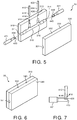
FIG. 5 illustrates a perspective view of a molding apparatus including first and second mold pieces and pins as herein described. -
FIG. 6 illustrates a perspective view of a molding apparatus as herein described with a first and second mold pieces closed together. -
FIG. 7 illustrates a perspective view of pins as herein described in contact with each other. -
FIG. 8 illustrates a plan view of a respiratory nosepiece according to an embodiment of the invention including an oral sampling port. -
FIG. 9 illustrates a perspective view of a respiratory nosepiece according to an embodiment of the invention, including an oral sampling port. -
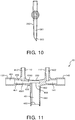
FIG. 10 illustrates a side plan view of an oral sampling port of a respiratory nosepiece according to an embodiment of the invention. -
FIG. 11 illustrates a cross-sectional view of a respiratory nosepiece according to an embodiment of the invention, having an oral sampling port and including pins. - In the following detailed description, for purposes of explanation and not limitation, representative embodiments and comparative examples disclosing specific details are set forth in order to provide a thorough understanding of the present teachings. However, it will be apparent to one having ordinary skill in the art having had the benefit of the present disclosure that other embodiments according to the present teachings that depart from the specific details disclosed herein remain within the scope of the appended claims. Moreover, descriptions of well-known apparatuses and methods may be omitted so as to not obscure the description of the representative embodiments.
- In view of the foregoing, various embodiments and implementations of the present invention are directed to a respiratory nosepiece for gas sampling. Herein described is a method of manufacturing a respiratory nosepiece for gas sampling.
-
FIG. 1 illustrates a plan view ofrespiratory nosepiece 10 according to an embodiment of the invention including insertedtubes Respiratory nosepiece 10 is made by injection molding, and may be a polymer material such as polyvinyl chloride, thermoplastic elastomer, silicone, ethylene propylene diene monomer, or urethane that has sufficiently low durometer to be flexible, such as in a range of about Shore A15 to Shore A90 for example. -
Respiratory nosepiece 10 as shown inFIG. 1 is a nasal-only configuration, and includes firstnasal prong 110 connected tofirst side port 130, secondnasal prong 120 connected tosecond side port 140, and contouredbridge section 150 extending between first andsecond side ports nasal prongs nasal prongs
suitable for a wide range of patient populations.First channel 112 depicted by dashed lines extends through firstnasal prong 110 along a first (vertical) direction.First channel 112 has a substantially consistent diameter along the length of firstnasal prong 110 that may be in a range of about 40-60 thousands of an inch. In an example embodiment,first channel 112 may taper slightly inward as it extends downward through firstnasal prong 110. - First and
second side ports FIG. 1 are both connectable to tubes having different first and second diameters.First side port 130 includes asecond channel 131 depicted by dashed lines that extends through it along a second (horizontal) direction orthogonal to the first (vertical) direction.Second channel 131 has afirst end 132 that is configured to insertably receive the tubes, and asecond end 133 in communication withfirst channel 112 of firstnasal prong 110.Second channel 131 includesfirst section 134 atfirst end 132 that has the first diameter,second section 136 having the second diameter,first step 135 between first andsecond sections second step 137 betweensecond section 136 andsecond end 133 ofsecond channel 131.Second channel 131 further includesadditional section 1361 having a third diameter smaller than the second diameter,additional section 1361 extending betweensecond step 137 andsecond end 133 ofsecond channel 131. -
First step 135 is a transition having tapered diameter between first andsecond sections second channel 131. First step 135 functions as a hard stop that prevents insertion of first tubes, such astube 192 which has the first diameter, intosecond section 136, so thatsecond section 136 is not occluded by over-insertion oftube 192.Second step 137 is a transition betweensecond section 136 andsecond end 133 ofsecond channel 131.Second step 137 functions as a hard stop to prevent insertion of second tubes, such astube 194 having the second diameter, further intosecond channel 131, so thatadditional section 1361 is not occluded by over-insertion oftube 194. Unlikefirst step 135,second step 137 is located only along an upper inner circumference ofsecond channel 131 and consists of a wall portion which functions as a hard stop that abuts against an end face of an inserted tube such astube 194 to prevent further insertion of the tube intosecond channel 131. Also,second end 133 ofsecond channel 131 has a spherical shape at 138 to smoothly direct flow of gas between first andsecond channels -
Third channel 122 shown inFIG. 1 depicted by dashed lines extends through secondnasal prong 120 along the first (vertical) direction.Third channel 122 has a substantially consistent diameter along the length of secondnasal prong 120 that may be in a range of about 0,10-0,15 cm [40-60 thousands of an inch].Third channel 122 may taper slightly inward as it extends downward through secondnasal prong 120. -
Second side port 140 includes afourth channel 141 depicted by dashed lines that extends through it along the second (horizontal) direction, orthogonal to the first (vertical) direction.Fourth channel 141 has afirst end 142 that is configured to insertably receive the tubes, and asecond end 143 in communication withthird channel 122 of secondnasal prong 120.Fourth channel 141 includesthird section 144 atfirst end 142 that has the first diameter,fourth section 146 having the second diameter,third step 145 between third andfourth sections fourth step 147 betweenfourth section 146 andsecond end 143 offourth channel 141.Fourth channel 141 further includesadditional section 1461 having a third diameter smaller than the second diameter,additional section 1461 extending betweenfourth step 147 andsecond end 143 offourth channel 141. -
Third step 145 is a transition having tapered diameter between third andfourth sections fourth channel 141.Third step 145 functions as a hard stop that prevents insertion of first tubes, such astube 192 which has the first diameter, intofourth section 146, so thatfourth section 146 is not occluded by over-insertion oftube 192.Fourth step 147 is a transition betweenfourth section 146 andsecond end 143 offourth channel 141.Fourth step 147 functions as a hard stop to prevent insertion of second tubes, such astube 194 having the second diameter, further intofourth channel 141, so thatadditional section 1461 is not occluded by over-insertion oftube 194. Unlikethird step 145,fourth step 147 is located only along an upper inner circumference offourth channel 141 and consists of a wall portion which functions as a hard stop that abuts against an end face of an inserted tube such astube 194 to prevent further insertion of the tube intofourth channel 141. Also,second end 143 offourth channel 141 has a spherical shape at 148 to smoothly direct flow of gas between third andfourth channels -
Tube 192 connected tofirst side port 130 and inserted intofirst section 134 ofsecond channel 131 as shown inFIG. 1 may be an oxygen delivery tube connected to an oxygen delivery system (not shown).Tube 192 may have an outer diameter of about 0,318 cm[125 thousands of an inch], substantially corresponding to the first diameter offirst section 134 ofsecond channel 131 andthird section 144 offourth channel 141.Tube 194 connected tosecond side port 140 and inserted throughthird section 144 and intofourth section 146 offourth channel 141 as shown inFIG. 1 may be a carbon dioxide (CO2) sampling tube connected to a respiratory gas monitoring device (not shown).Tube 194 may have an outer diameter of about 0,236 cm [93 thousands of an inch], substantially corresponding to the second diameter ofsecond section 136 ofsecond channel 131 andfourth section 146 offourth channel 141. -
Tubes 192 may be bonded to first andthird steps tubes 194 may be bonded to second andfourth steps Tubes fourth channels tubes - Moreover, as should be readily understood, first and
second side ports FIG. 1 are both configured to insertably receive eithertube 192 which may be an oxygen delivery tube, ortube 194 which may be a CO2 gas sampling tube. In the example embodiment as shown inFIG. 1 , by insertion oftube 192 intofirst side port 130 and insertion oftube 194 intosecond side port 140, a gas sampling cannulae includingrespiratory nosepiece 10 andtubes first side port 130 to a respiratory gas monitoring device (not shown) and by which oxygen may be delivered from an oxygen supply (not shown) to the patient viasecond side port 140. In a further embodiment, by insertion oftubes 192 into both first andsecond side ports respiratory nosepiece 10 andtubes 192 may thus be provided by which respiratory CO2 gas exhaled by the patient may be delivered to a respiratory gas monitoring device (not shown) via both first andsecond side ports second side ports respiratory nosepiece 10 configured as shown inFIG. 1 thus efficiently combines the functionality of two different types of respiratory nosepieces. - As described,
respiratory nosepiece 10 may be made of sufficiently low durometer material to be flexible. Whenrespiratory nosepiece 10 is attached to a patient with first and secondnasal prongs bridge section 150 shown inFIG. 1 may be positioned under the nose to supportrespiratory nosepiece 10 against the nasal philtrum of the patient, andtubes second side ports top surface 151 of contouredbridge section 150 may be curved so that a height of contouredbridge section 150 along the first (vertical) direction may be reduced near a center point between first and secondnasal prongs contoured bridge section 150 that extends away from the nasal columella of the patient whenrespiratory nosepiece 10 is attached, avoiding uncomfortable chafing. -
FIG. 2 illustrates a perspective view ofrespiratory nosepiece 10 according to an embodiment of the invention. First and secondnasal prongs second side ports bridge section 150 includingtop surface 151 ofrespiratory nosepiece 10 are shown inFIG. 2 . -
FIG. 3 illustrates a bottom plan view ofrespiratory nosepiece 10 according to an embodiment of the invention, from an underside of the view shown inFIG. 1 .Contoured bridge section 150 as shown inFIG. 3 includes side surfaces (sidewalls) 152 and 153 that are adjacenttop surface 151. Side surfaces 152 and 153 as shown may be curved inward so that a width between side surfaces 152 and 153 of contouredbridge section 150 may be reduced near a center point between first and secondnasal prongs 110 and 120 (not shown). The reduction in width allows for greater flexibility atcontoured bridge section 150, thus providing a more comfortable fit against the nasal philtrum of the patient. -
FIG. 4 illustrates a cross-sectional view ofrespiratory nosepiece 10 according to an embodiment of the invention, including first andsecond pins second pins FIGS. 5 and 6 , to respectively formfirst channel 112 within firstnasal prong 110 andsecond channel 131 withinfirst side port 130. First andsecond pins FIG. 4 thus shows a cross-section ofrespiratory nosepiece 10 after injection of mold material, but before retraction of first andsecond pins -
First pin 412 as shown inFIG. 4 is substantially cylindrical, includingdistal end 414 that has a substantiallyflat face 416.First pin 412 has a substantially consistent diameter along its length, but may be slightly tapered towarddistal end 414 so as to be more easily retractable after injection of the molding material.Second pin 431 includes first and second ends 432 and 433,first section 434 having the first diameter,second section 436 having the second diameter, andthird section 4361 having aflat sidewall portion 439 aligned underneath and in direct contact withfirst pin 412 when first andsecond pins FIG. 7 , first andsecond pins flat face 416 atdistal end 414 offirst pin 412 is brought directly into contact withflat sidewall portion 439 ofsecond pin 431 so thatfirst pin 412 contactsflat sidewall portion 439 ofsecond pin 431 substantially without any gaps or spaces there between, thus avoiding resin flash into first andsecond channels respiratory nosepiece 10 during injection molding. First andsecond pins 412 and 413 thus include respective opposing contact areas having flat pin-on-pin geometry. A smooth transition may thus be provided between first andsecond channels respiratory nosepiece 10 without turbulence of gas flow. - As further shown in
FIG. 4 ,second pin 431 includes steppedportion 435 as a transition between first andsecond sections portion 435 formingfirst step 135 withinsecond channel 131 ofrespiratory nosepiece 10.Second pin 431 further includeswall 437 as a transition betweensecond section 436 andflat sidewall portion 439 ofthird section 4361.Wall 437 formssecond step 137 withinsecond channel 131. First andsecond sections second pin 431 are substantially cylindrical, whilethird section 4361 includes a substantially cylindrical bottom portion havingflat sidewall portion 439 as a top surface. As further shown, second (distal) end 433 ofsecond pin 431 has spherical shapedsection 438 that correspondingly forms thespherical shape 138 atsecond end 133 withinsecond channel 131, which helps to smoothly redirect gas flow between first andsecond channels -
Respiratory nosepiece 10 shown inFIG. 4 further includesthird pin 422 within secondnasal prong 120 that formsthird channel 122 ofrespiratory nosepiece 10, andfourth pin 441 withinsecond side port 140 that formsfourth channel 141. Third andfourth pins second pins fourth pins -
FIG. 5 illustrates a perspective view ofmolding apparatus 30 including first andsecond mold pieces first pin 412,second pin 431,third pin 422 andfourth pin 441, as herein described.Molding apparatus 30 is shown inFIG. 5 during an initial position with first andsecond mold pieces fourth pins FIG. 6 illustrates a perspective view ofmolding apparatus 30 as herein described, with first andsecond mold pieces -
First mold piece 310 as shown inFIG. 5 includescavity 316 which forms a first half ofrespiratory nosepiece 10.Second mold piece 330 includes an additional cavity (not shown) which forms a second half ofrespiratory nosepiece 10. In a molding process, first andsecond mold pieces cavity 316 and the additional cavity (not shown).Grooves first mold piece 310, while correspondingmating grooves second mold piece 330. As shown inclosed mold apparatus 30 ofFIG. 6 , the mating grooves of first andsecond mold pieces fourth pins closed mold apparatus 30 and into the nosepiece cavity. - When the pins are fully inserted,
flat face 416 atdistal end 414 offirst pin 412 shown inFIG. 5 will be in direct contact withflat sidewall portion 439 atsecond end 433 ofsecond pin 431 substantially without any gap there between, as shown inFIG. 7 . First andsecond pins mold apparatus 30 respectively form first andsecond channels respiratory nosepiece 10, first andsecond channels flat face 426 atdistal end 424 ofthird pin 422 shown inFIG. 5 will be in direct contact withflat sidewall portion 449 atsecond end 443 offourth pin 441 substantially without any gap there between. Third andfourth pins mold apparatus 30 respectively form third andfourth channels respiratory nosepiece 10, third andfourth channels - Additionally, an injection port (not shown) may be formed through
first mold piece 310 to supply mold material at a location such aslocation 318 shown inFIG. 5 . Positioning of the injection port to supply mold material to the nosepiece cavity atlocation 318 ensures thattop surface 151 and/orside surfaces bridge section 150 ofrespiratory nosepiece 10 as shown inFIGS. 1-3 will be substantially smooth without bumps, minimizing irritation whenrespiratory nosepiece 10 is attached to the patient. -
FIG. 7 illustrates a perspective view of first andsecond pins Distal end 414 offirst pin 412 includesflat face 416 in direct contact withflat sidewall portion 439 atsecond end 433 ofsecond pin 431 substantially without any gap there between, to minimize and avoid resin flash into respective first andsecond channels respiratory nosepiece 10. -
FIG. 8 illustrates a perspective view ofrespiratory nosepiece 20 according to an embodiment of the invention, including anoral sampling port 260.Respiratory nosepiece 20 as shown inFIG. 8 includes firstnasal prong 110,first channel 112,first side port 130,second channel 131, secondnasal prong 120,third channel 122,second side port 140 andfourth channel 141 such as described with respect toFIG. 1 , and for which detailed description with reference toFIG. 8 is omitted. First throughfourth channels nasal prong 110,first side port 130, secondnasal prong 120 andsecond side port 140 are depicted by dashed lines. -
Respiratory nosepiece 20 as shown inFIG. 8 further includesoral sampling port 260 andfifth channel 251 inbridge section 250.Fifth channel 251 includesfirst end 252 in communication withsecond channel 131 withinfirst side port 130, and second end 253.Oral sampling port 260 includessixth channel 261 which extends along the first (vertical) direction.Sixth channel 261 includesfirst end 262 in communication with second end 253 offifth channel 251, andsecond end 263.Oral sampling port 260 is configured so that whenrespiratory nosepiece 20 is attached to a patient,second end 263 may be adjacent a mouth of the patient. As shown inFIG. 10 ,second end 263 oforal sampling port 260 may be beveled toward the mouth of the patient. -
Respiratory nosepiece 20 as shown inFIG. 8 is designed for patients that are prone to mouth breathing in addition to or in place of nose breathing. In an example embodiment,first side port 130 ofrespiratory nosepiece 20 as shown inFIG. 8 may be connected to a respiratory gas monitoring device (not shown) via a CO2 sampling tube such astube 194 shown inFIG. 1 which has an outer diameter substantially corresponding to the second diameter.First side port 130 ofrespiratory nosepiece 20 as shown inFIG. 8 may be connected to an oxygen supply (not shown) via an oxygen delivery tube such astube 192 shown inFIG. 1 which has an outer diameter substantially corresponding to the first diameter. -
FIG. 9 illustrates a perspective view ofrespiratory nosepiece 20 according to an embodiment of the invention, includingoral sampling port 260. First and secondnasal prongs second side ports bridge section 250 andoral sampling port 260 ofrespiratory nosepiece 20 are shown inFIG. 9 . -
FIG. 10 illustrates a side plan view oforal sampling port 260 ofrespiratory nosepiece 20 according to an embodiment of the invention. As shown inFIG. 9 ,second end 263 ofsixth channel 261 oforal sampling port 260 is beveled toward a mouth of the patient (not shown and which would be located to the left of the figure). -
FIG. 11 illustrates a cross-sectional view ofrespiratory nosepiece 20 according to an embodiment of the invention, including fifth andsixth pins Fifth pin 451 is insertable into a molding apparatus such as shown inFIGS. 5 and 6 during an injection molding process to formsecond channel 131 andfifth channel 251 withinbridge section 250 ofrespiratory nosepiece 20 shown inFIG. 8 .Sixth pin 461 is insertable into the molding apparatus during the injection molding process to formsixth channel 261 withinoral sampling port 260.Fifth pin 451 may be a pin similar in construction tosecond pin 431 described with respect toFIG. 4 , including first, second andthird sections third sections second pin 431, and further includingfourth section 4562 extending fromthird section 4561.Fifth pin 451 may includeflat sidewall portion 459 atfourth section 4562.Sixth pin 461 may have aflat end face 466 at second (distal)end 462. When fully inserted into the corresponding molding apparatus,flat end face 466 ofsixth pin 461 is brought into direct contact withflat sidewall portion 459 atfourth section 4562 offifth pin 451 with no gaps there between, to minimize and avoid resin flash into fifth andsixth channels respiratory nosepiece 20. - As a variation described herein, a multi-cavity tool may be provided including first and
second mold pieces cavity 316 as shown inFIG. 5 for example repeated multiple times within an injection mold tool frame, with each cavity/core combination having its own set of pins. The overall mechanism of the injection mold tool would correspondingly actuate the pins for each cavity/core set. - All definitions, as defined and used herein, should be understood to control over dictionary definitions, definitions in documents incorporated by reference, and/or ordinary meanings of the defined terms.
- The indefinite articles "a" and "an," as used herein in the specification and in the claims, unless clearly indicated to the contrary, should be understood to mean "at least one."
- The phrase "and/or," as used herein in the specification and in the claims, should be understood to mean "either or both" of the elements so conjoined, i.e., elements that are conjunctively present in some cases and disjunctively present in other cases. Multiple elements listed with "and/or" should be construed in the same fashion, i.e., "one or more" of the elements so conjoined. Other elements may optionally be present other than the elements specifically identified by the "and/or" clause, whether related or unrelated to those elements specifically identified. Thus, as a non-limiting example, a reference to "A and/or B", when used in conjunction with open-ended language such as "comprising" can refer, in one embodiment, to A only (optionally including elements other than B); in another embodiment, to B only (optionally including elements other than A); in yet another embodiment, to both A and B (optionally including other elements); etc.
- As used herein in the specification and in the claims, "or" should be understood to have the same meaning as "and/or" as defined above. For example, when separating items in a list, "or" or "and/or" shall be interpreted as being inclusive, i.e., the inclusion of at least one, but also including more than one, of a number or list of elements, and, optionally, additional unlisted items. Only terms clearly indicated to the contrary, such as "only one of' or "exactly one of," or, when used in the claims, "consisting of," will refer to the inclusion of exactly one element of a number or list of elements. In general, the term "or" as used herein shall only be interpreted as indicating exclusive alternatives (i.e. "one or the other but not both") when preceded by terms of exclusivity, such as "either," "one of," "only one of," or "exactly one of." "Consisting essentially of," when used in the claims, shall have its ordinary meaning as used in the field of patent law.
- As used herein in the specification and in the claims, the phrase "at least one," in reference to a list of one or more elements, should be understood to mean at least one element selected from any one or more of the elements in the list of elements, but not necessarily including at least one of each and every element specifically listed within the list of elements and not excluding any combinations of elements in the list of elements. This definition also allows that elements may optionally be present other than the elements specifically identified within the list of elements to which the phrase "at least one" refers, whether related or unrelated to those elements specifically identified. Thus, as a non-limiting example, "at least one of A and B" (or, equivalently, "at least one of A or B," or, equivalently "at least one of A and/or B") can refer, in one embodiment, to at least one, optionally including more than one, A, with no B present (and optionally including elements other than B); in another embodiment, to at least one, optionally including more than one, B, with no A present (and optionally including elements other than A); in yet another embodiment, to at least one, optionally including more than one, A, and at least one, optionally including more than one, B (and optionally including other elements); etc.
- It should also be understood that, unless clearly indicated to the contrary, in any methods described herein that include more than one step or act, the order of the steps or acts of the method is not necessarily limited to the order in which the steps or acts of the method are recited.
- In the claims, as well as in the specification above, all transitional phrases such as "comprising," "including," "carrying," "having," "containing," "involving," "holding," "composed of," and the like are to be understood to be open-ended, i.e., to mean including but not limited to. Only the transitional phrases "consisting of' and "consisting essentially of' shall be closed or semi-closed transitional phrases, respectively, as set forth in the United States Patent Office Manual of Patent Examining Procedures, Section 211.
Claims (12)
- A respiratory nosepiece (10, 20) comprising:a first nasal prong (110) configured to be insertable into a nostril of a patient, a first channel (112) extending through the first nasal prong (110) along a first direction; anda first side port (130) connectable to tubes (192, 194) having different first and second diameters, the first side port (130) including a second channel (131) extending along a second direction orthogonal with respect to the first direction, the second channel (131) having a first end (132) configured to insertably receive the tubes (192, 194) and having a second end (133) in communication with the first channel (112),the second channel (131) comprising a first section (134) at the first end (132) having the first diameter, a second section (136) having the second diameter, a first step (135) between the first (134) and second sections (136), and a second step (137) between the second section (136) and the second end (133) of the second channel (131), the first step (135) configured to prevent insertion of first tubes (192) having the first diameter into the second section (136) and the second step (137) configured to prevent insertion of second tubes (194) having the second diameter further into the second channel (131), wherein the second step (137) consists of a wall portion, which is located only along an upper inner circumference of the second channel (131) and which functions as a hard stop that abuts against an end face of an inserted tube (194) to prevent further insertion of the tube (194) into the second channel (131).
- The respiratory nosepiece (10, 20) of claim 1, further comprising:a second nasal prong (120) configured to be insertable into another nostril of the patient, a third channel (122) extending through the second nasal prong (120) along the first direction; anda second side port (140) connectable to the tubes (192, 194), the second side port (140) including a fourth channel (141) extending along the second direction, the fourth channel (141) having a first end (142) configured to insertably receive the tubes (192, 194) and a second end (143) in communication with the third channel (122),the fourth channel (141) comprising a third section (144) at the first end (142) having the first diameter, a fourth section (146) having the second diameter, a third step (145) between the third (144) and fourth sections (146), and a fourth step (147) between the fourth section (146) and the second end (143) of the fourth channel (141), the third step (145) configured to prevent insertion of the first tubes (192) into the third section (144) and the fourth step (147) configured to prevent insertion of the second tubes (194) further into the fourth channel (141).
- The respiratory nosepiece (10, 20) of claim 2, further comprising a bridge section (150, 250) extending between the first (130) and second side ports (140) and configured to support the respiratory nosepiece (10) against the patient.
- The respiratory nosepiece (10, 20) of claim 3, wherein a top surface (151) of the bridge section (150, 250) is curved so that a height of the bridge section (150, 250) along the first direction is reduced near a center point between the first (110) and second nasal prongs (120).
- The respiratory nosepiece (10, 20) of claim 4, wherein side surfaces of the bridge section (150, 250) adjacent the top surface (151) are curved so that a width between the side surfaces of the bridge section is reduced near the center point between the first (110) and second nasal prongs (120).
- The respiratory nosepiece (10, 20) of claim 3, further comprising:a fifth channel (251) in the bridge section (150, 250), the fifth channel (251) having a first end (252) in communication with the second end (133) of the second channel (131) and having a second end; andan oral sampling port (260) including a sixth channel (261) extending along the first direction, the sixth channel (261) having a first end (262) in communication with the second end of the fifth channel (251) and having a second end (263) configured to be adjacent to a mouth of the patient.
- The respiratory nosepiece (10, 20) of claim 6, wherein the oral sampling port (260) is beveled toward the mouth of the patient at the second end (263) of the sixth channel (261).
- The respiratory nosepiece (10, 20) of claim 1, wherein the second channel (131) further comprises an additional section (1361) having a third diameter smaller than the second diameter, the additional section (1361) extending between the second step (137) and the second end (133) of the second channel (131).
- The respiratory nosepiece (10, 20) of claim 1, wherein the second end (133) of the second channel (131) has a spherical shape (138) configured to smoothly redirect flow of gas between the first (112) and second channels (131).
- The respiratory nosepiece (10, 20) of claim 1, comprised of polyvinyl chloride, thermoplastic elastomer, silicone, ethylene propylene diene monomer, or urethane having a sufficiently low durometer to be flexible.
- A respiratory nosepiece (10, 20) comprising:first (110) and second (120) nasal prongs configured to be insertable into nostrils of a patient;a first side port (130) having a first channel (131), the first channel (131) having a first end (132) configured to insertably receive tubes (192, 194) having different first and second diameters and a second end (133) in communication with the first nasal prong (110); anda second side port (140) having a second channel (141), the second channel (141) having a first end (142) configured to insertably receive the tubes (192, 194) and a second end (143) in communication with the second nasal prong (120),each of the first (131) and second (141) channels comprising a first section (134, 144) having the first diameter at the first end (132, 142) followed by a second section (136, 146) having the second diameter, wherein the first diameter is greater than the second diameter,a third section (1361, 1461) following the second section (136, 146), the third section (1361, 1461) having a third diameter smaller than the second diameter,a first step (135, 145) between the first (134, 144) and second (136, 146) section, and a second step (137, 147) between the second section (136, 146) and the third section (1361, 1461), the first step (135, 145) configured to prevent insertion of first tubes (192) having the first diameter into the second section (136, 146) and the second step (137, 147) configured to prevent insertion of second tubes (194) having the second diameter further into the corresponding channel of the first (131) and second (141) channels, wherein the second step (137, 147) of each of the first (131) and second (141) channels consists of a wall portion, which is only located along an upper inner circumference of the corresponding channel of the first (131) and second (141) channels and which functions as a hard stop that abuts against an end face of an inserted tube (194) to prevent further insertion of the tube (194) into the corresponding channel of the first (131) and second (141) channels.
- The respiratory nosepiece (10, 20) of claim 11, further comprising:a bridge section (150, 250) extending between the first (130) and second (140) side ports and configured to support the nosepiece (10, 20) against the patient;a third channel (251) in the bridge section (150, 250), the third channel (251) having a first end (252) in communication with the second end (133) of the first channel (131) and having a second end; andan oral sampling port (260) extending along a same direction as the first (110) and second nasal prongs (120), the oral sampling port (260) including a fourth channel (261) having a first end (262) in communication with the second end of the third channel (251) and having a second end (263) configured to be adjacent to a mouth of the patient.
Applications Claiming Priority (2)
| Application Number | Priority Date | Filing Date | Title |
|---|---|---|---|
| US201461938729P | 2014-02-12 | 2014-02-12 | |
| PCT/IB2015/051045 WO2015121815A1 (en) | 2014-02-12 | 2015-02-12 | Flexible low deadspace respiratory nosepiece for gas sampling cannulae and method of manufacturing respiratory nosepiece |
Publications (2)
| Publication Number | Publication Date |
|---|---|
| EP3104924A1 EP3104924A1 (en) | 2016-12-21 |
| EP3104924B1 true EP3104924B1 (en) | 2018-08-29 |
Family
ID=52595380
Family Applications (1)
| Application Number | Title | Priority Date | Filing Date |
|---|---|---|---|
| EP15706942.8A Active EP3104924B1 (en) | 2014-02-12 | 2015-02-12 | Flexible low deadspace respiratory nosepiece for gas sampling cannulae |
Country Status (6)
| Country | Link |
|---|---|
| US (1) | US10471228B2 (en) |
| EP (1) | EP3104924B1 (en) |
| JP (1) | JP6445576B2 (en) |
| CN (1) | CN105992560B (en) |
| MX (1) | MX2016010311A (en) |
| WO (1) | WO2015121815A1 (en) |
Families Citing this family (15)
| Publication number | Priority date | Publication date | Assignee | Title |
|---|---|---|---|---|
| JP6721611B2 (en) * | 2015-01-23 | 2020-07-15 | マシモ スウェーデン アーベーMasimo Sweden Ab | Nasal/oral cannula system and manufacturing |
| CN211798112U (en) | 2015-06-30 | 2020-10-30 | 蒸汽热能公司 | Nasal cannula and respiratory therapy system |
| US10220174B2 (en) * | 2016-02-17 | 2019-03-05 | Christine M. Huerta | Septi-cannula |
| WO2018005851A1 (en) | 2016-06-30 | 2018-01-04 | Vapotherm, Inc. | Cannula device for high flow therapy |
| CN114306861A (en) * | 2016-08-31 | 2022-04-12 | 费雪派克医疗保健有限公司 | Patient interface, system and method |
| DE102017004224A1 (en) * | 2016-12-13 | 2018-11-08 | Drägerwerk AG & Co. KGaA | Nasal cannula for high-flow ventilation |
| USD859646S1 (en) * | 2017-01-23 | 2019-09-10 | Koninklijke Philips N.V. | Nasal cannula |
| USD873410S1 (en) * | 2017-01-24 | 2020-01-21 | Koninklijke Philips N.V. | Nasal cannula with oral scoop |
| AU2018327338A1 (en) * | 2017-09-08 | 2020-03-19 | Vapotherm, Inc. | Birfurcated cannula device |
| USD917042S1 (en) * | 2017-12-29 | 2021-04-20 | Koninklijke Philips N.V. | Nasal cannula |
| US11583650B2 (en) | 2019-06-28 | 2023-02-21 | Vapotherm, Inc. | Variable geometry cannula |
| US11607064B2 (en) * | 2019-08-06 | 2023-03-21 | Dart Industries Inc. | Reusable drinking straw |
| AU2020353666A1 (en) | 2019-09-26 | 2022-04-14 | Vapotherm, Inc. | Internal cannula mounted nebulizer |
| USD957622S1 (en) * | 2019-10-16 | 2022-07-12 | Aires Medical LLC | Nasal cannula |
| CN214050088U (en) * | 2020-10-30 | 2021-08-27 | 北京怡和嘉业医疗科技股份有限公司 | Nasal plug for nasal oxygen catheter, nasal oxygen catheter and ventilation treatment equipment |
Family Cites Families (21)
| Publication number | Priority date | Publication date | Assignee | Title |
|---|---|---|---|---|
| DE2845346B2 (en) * | 1978-10-18 | 1980-11-27 | Sterimed Gesellschaft Fuer Medizinischen Bedarf Mbh, 6600 Saarbruecken | Connecting sleeve |
| US4989599A (en) * | 1989-01-26 | 1991-02-05 | Puritan-Bennett Corporation | Dual lumen cannula |
| JPH05505119A (en) * | 1991-01-29 | 1993-08-05 | ピューリタン―ベネット コーポレイション | double lumen cannula |
| DK171592B1 (en) * | 1993-12-21 | 1997-02-17 | Maersk Medical As | Device for supplying oxygen and / or other gases to a patient |
| CN2231113Y (en) * | 1995-02-07 | 1996-07-17 | 宋进省 | Tracheal catheter through nasal cavity |
| CA2370995C (en) * | 2001-09-13 | 2010-08-17 | Fisher & Paykel Healthcare Limited | Breathing assistance apparatus |
| US20040182397A1 (en) * | 2003-03-21 | 2004-09-23 | Innomed Technologies, Inc. | Nasal interface including ventilation insert |
| US7472707B2 (en) * | 2003-08-06 | 2009-01-06 | Innomed Technologies, Inc. | Nasal interface and system including ventilation insert |
| US20060081257A1 (en) | 2004-08-31 | 2006-04-20 | Ross Krogh | Single use drug delivery components |
| US7383839B2 (en) * | 2004-11-22 | 2008-06-10 | Oridion Medical (1987) Ltd. | Oral nasal cannula |
| JP2007229207A (en) * | 2006-03-01 | 2007-09-13 | Saitama Univ | Nasal cpap element |
| US20080105318A1 (en) | 2006-10-11 | 2008-05-08 | Leone James E | Turbulence Minimizing Device for Multi-Lumen Fluid Infusing Systems and Method for Minimizing Turbulence in Such Systems |
| US8371304B2 (en) | 2007-12-28 | 2013-02-12 | Carefusion | Continuous positive airway pressure device and method |
| CA2713012A1 (en) * | 2008-01-25 | 2009-07-30 | Salter Labs | Respiratory therapy system including a nasal cannula assembly |
| US8707954B2 (en) | 2008-10-09 | 2014-04-29 | Daniel A. McCarthy | Air/oxygen supply system and method |
| CA2757588C (en) | 2009-04-02 | 2017-01-03 | Breathe Technologies, Inc. | Methods, systems and devices for non-invasive open ventilation with gas delivery nozzles in free space |
| JP3157855U (en) * | 2009-12-17 | 2010-03-04 | アトムメディカル株式会社 | Oxygen supply equipment |
| WO2012045051A1 (en) * | 2010-09-30 | 2012-04-05 | Breathe Technologies, Inc. | Methods, systems and devices for humidifying a respiratory tract |
| US20140005565A1 (en) * | 2012-06-29 | 2014-01-02 | Steven J. Derrick | Oral/nasal cannula manifold |
| EP2928532A4 (en) * | 2012-12-07 | 2016-06-29 | Parion Sciences Inc | Nasal cannula for delivery of aerosolized medicaments |
| WO2015020538A1 (en) * | 2013-08-06 | 2015-02-12 | Fisher & Paykel Healthcare Limited | Infant cpap device, interface and system |
-
2015
- 2015-02-12 EP EP15706942.8A patent/EP3104924B1/en active Active
- 2015-02-12 WO PCT/IB2015/051045 patent/WO2015121815A1/en active Application Filing
- 2015-02-12 JP JP2016550746A patent/JP6445576B2/en active Active
- 2015-02-12 US US15/118,644 patent/US10471228B2/en active Active
- 2015-02-12 MX MX2016010311A patent/MX2016010311A/en unknown
- 2015-02-12 CN CN201580008412.2A patent/CN105992560B/en active Active
Also Published As
| Publication number | Publication date |
|---|---|
| US20170049986A1 (en) | 2017-02-23 |
| JP6445576B2 (en) | 2018-12-26 |
| JP2017506949A (en) | 2017-03-16 |
| WO2015121815A1 (en) | 2015-08-20 |
| CN105992560B (en) | 2019-06-04 |
| MX2016010311A (en) | 2016-10-17 |
| US10471228B2 (en) | 2019-11-12 |
| EP3104924A1 (en) | 2016-12-21 |
| CN105992560A (en) | 2016-10-05 |
Similar Documents
| Publication | Publication Date | Title |
|---|---|---|
| EP3104924B1 (en) | Flexible low deadspace respiratory nosepiece for gas sampling cannulae | |
| US9901702B2 (en) | Tracheal tube with connector insert | |
| EP2836265B1 (en) | Nasal cannula with pressure monitoring and pressure relief | |
| US10307557B2 (en) | Compressible cannula connector with release grip | |
| US9993607B2 (en) | Oral cannula | |
| US20230211105A1 (en) | Conforming nasal pillow | |
| CN104519937B (en) | For the compressible connector of internal prongs | |
| CN106102812B (en) | Fixing device | |
| US20110265797A1 (en) | Extendable tracheal tube | |
| JP2016501681A (en) | Tracheostomy tube with cannula connector | |
| CN215231273U (en) | Exchange guide kit of tracheal catheter and application | |
| CN203244662U (en) | Tracheal cannula saliva blocking and collecting device | |
| CN203989372U (en) | Novel tracheotomy tube | |
| CN213252270U (en) | Clinical multipurpose joint of trachea cannula for anesthesia department | |
| US20160206840A1 (en) | Airway device with multiple channels | |
| CN219049706U (en) | Sputum aspirator | |
| CN209475326U (en) | A kind of trachea cannula | |
| CN214049950U (en) | Sputum suction tube with bronchus plugging function | |
| CN211327603U (en) | Tracheal cannula for critically ill patients | |
| CN213077055U (en) | Mask oropharynx combined airway | |
| CN217938850U (en) | Device for lung expansion | |
| CN214550584U (en) | Intubation assembly | |
| CN209529853U (en) | Tracheal catheter | |
| CN208693970U (en) | The fixed throat cover air flue conduit pipe in multi-cavity road | |
| CN113082432A (en) | Guiding device |
Legal Events
| Date | Code | Title | Description |
|---|---|---|---|
| PUAI | Public reference made under article 153(3) epc to a published international application that has entered the european phase |
Free format text: ORIGINAL CODE: 0009012 |
|
| STAA | Information on the status of an ep patent application or granted ep patent |
Free format text: STATUS: REQUEST FOR EXAMINATION WAS MADE |
|
| 17P | Request for examination filed |
Effective date: 20160912 |
|
| AK | Designated contracting states |
Kind code of ref document: A1 Designated state(s): AL AT BE BG CH CY CZ DE DK EE ES FI FR GB GR HR HU IE IS IT LI LT LU LV MC MK MT NL NO PL PT RO RS SE SI SK SM TR |
|
| AX | Request for extension of the european patent |
Extension state: BA ME |
|
| DAX | Request for extension of the european patent (deleted) | ||
| STAA | Information on the status of an ep patent application or granted ep patent |
Free format text: STATUS: EXAMINATION IS IN PROGRESS |
|
| 17Q | First examination report despatched |
Effective date: 20170526 |
|
| RIC1 | Information provided on ipc code assigned before grant |
Ipc: B29L 31/00 20060101ALN20171219BHEP Ipc: B29C 45/36 20060101ALI20171219BHEP Ipc: A61M 16/08 20060101ALI20171219BHEP Ipc: B29C 45/26 20060101ALI20171219BHEP Ipc: A61M 16/06 20060101AFI20171219BHEP |
|
| GRAP | Despatch of communication of intention to grant a patent |
Free format text: ORIGINAL CODE: EPIDOSNIGR1 |
|
| STAA | Information on the status of an ep patent application or granted ep patent |
Free format text: STATUS: GRANT OF PATENT IS INTENDED |
|
| INTG | Intention to grant announced |
Effective date: 20180313 |
|
| GRAS | Grant fee paid |
Free format text: ORIGINAL CODE: EPIDOSNIGR3 |
|
| GRAA | (expected) grant |
Free format text: ORIGINAL CODE: 0009210 |
|
| STAA | Information on the status of an ep patent application or granted ep patent |
Free format text: STATUS: THE PATENT HAS BEEN GRANTED |
|
| AK | Designated contracting states |
Kind code of ref document: B1 Designated state(s): AL AT BE BG CH CY CZ DE DK EE ES FI FR GB GR HR HU IE IS IT LI LT LU LV MC MK MT NL NO PL PT RO RS SE SI SK SM TR |
|
| REG | Reference to a national code |
Ref country code: GB Ref legal event code: FG4D |
|
| REG | Reference to a national code |
Ref country code: CH Ref legal event code: EP |
|
| REG | Reference to a national code |
Ref country code: AT Ref legal event code: REF Ref document number: 1034412 Country of ref document: AT Kind code of ref document: T Effective date: 20180915 |
|
| REG | Reference to a national code |
Ref country code: IE Ref legal event code: FG4D |
|
| REG | Reference to a national code |
Ref country code: DE Ref legal event code: R096 Ref document number: 602015015497 Country of ref document: DE |
|
| REG | Reference to a national code |
Ref country code: NL Ref legal event code: MP Effective date: 20180829 |
|
| REG | Reference to a national code |
Ref country code: LT Ref legal event code: MG4D |
|
| PG25 | Lapsed in a contracting state [announced via postgrant information from national office to epo] |
Ref country code: BG Free format text: LAPSE BECAUSE OF FAILURE TO SUBMIT A TRANSLATION OF THE DESCRIPTION OR TO PAY THE FEE WITHIN THE PRESCRIBED TIME-LIMIT Effective date: 20181129 Ref country code: SE Free format text: LAPSE BECAUSE OF FAILURE TO SUBMIT A TRANSLATION OF THE DESCRIPTION OR TO PAY THE FEE WITHIN THE PRESCRIBED TIME-LIMIT Effective date: 20180829 Ref country code: NO Free format text: LAPSE BECAUSE OF FAILURE TO SUBMIT A TRANSLATION OF THE DESCRIPTION OR TO PAY THE FEE WITHIN THE PRESCRIBED TIME-LIMIT Effective date: 20181129 Ref country code: NL Free format text: LAPSE BECAUSE OF FAILURE TO SUBMIT A TRANSLATION OF THE DESCRIPTION OR TO PAY THE FEE WITHIN THE PRESCRIBED TIME-LIMIT Effective date: 20180829 Ref country code: LT Free format text: LAPSE BECAUSE OF FAILURE TO SUBMIT A TRANSLATION OF THE DESCRIPTION OR TO PAY THE FEE WITHIN THE PRESCRIBED TIME-LIMIT Effective date: 20180829 Ref country code: FI Free format text: LAPSE BECAUSE OF FAILURE TO SUBMIT A TRANSLATION OF THE DESCRIPTION OR TO PAY THE FEE WITHIN THE PRESCRIBED TIME-LIMIT Effective date: 20180829 Ref country code: GR Free format text: LAPSE BECAUSE OF FAILURE TO SUBMIT A TRANSLATION OF THE DESCRIPTION OR TO PAY THE FEE WITHIN THE PRESCRIBED TIME-LIMIT Effective date: 20181130 Ref country code: RS Free format text: LAPSE BECAUSE OF FAILURE TO SUBMIT A TRANSLATION OF THE DESCRIPTION OR TO PAY THE FEE WITHIN THE PRESCRIBED TIME-LIMIT Effective date: 20180829 Ref country code: IS Free format text: LAPSE BECAUSE OF FAILURE TO SUBMIT A TRANSLATION OF THE DESCRIPTION OR TO PAY THE FEE WITHIN THE PRESCRIBED TIME-LIMIT Effective date: 20181229 |
|
| REG | Reference to a national code |
Ref country code: AT Ref legal event code: MK05 Ref document number: 1034412 Country of ref document: AT Kind code of ref document: T Effective date: 20180829 |
|
| PG25 | Lapsed in a contracting state [announced via postgrant information from national office to epo] |
Ref country code: LV Free format text: LAPSE BECAUSE OF FAILURE TO SUBMIT A TRANSLATION OF THE DESCRIPTION OR TO PAY THE FEE WITHIN THE PRESCRIBED TIME-LIMIT Effective date: 20180829 Ref country code: AL Free format text: LAPSE BECAUSE OF FAILURE TO SUBMIT A TRANSLATION OF THE DESCRIPTION OR TO PAY THE FEE WITHIN THE PRESCRIBED TIME-LIMIT Effective date: 20180829 Ref country code: HR Free format text: LAPSE BECAUSE OF FAILURE TO SUBMIT A TRANSLATION OF THE DESCRIPTION OR TO PAY THE FEE WITHIN THE PRESCRIBED TIME-LIMIT Effective date: 20180829 |
|
| PG25 | Lapsed in a contracting state [announced via postgrant information from national office to epo] |
Ref country code: EE Free format text: LAPSE BECAUSE OF FAILURE TO SUBMIT A TRANSLATION OF THE DESCRIPTION OR TO PAY THE FEE WITHIN THE PRESCRIBED TIME-LIMIT Effective date: 20180829 Ref country code: PL Free format text: LAPSE BECAUSE OF FAILURE TO SUBMIT A TRANSLATION OF THE DESCRIPTION OR TO PAY THE FEE WITHIN THE PRESCRIBED TIME-LIMIT Effective date: 20180829 Ref country code: AT Free format text: LAPSE BECAUSE OF FAILURE TO SUBMIT A TRANSLATION OF THE DESCRIPTION OR TO PAY THE FEE WITHIN THE PRESCRIBED TIME-LIMIT Effective date: 20180829 Ref country code: RO Free format text: LAPSE BECAUSE OF FAILURE TO SUBMIT A TRANSLATION OF THE DESCRIPTION OR TO PAY THE FEE WITHIN THE PRESCRIBED TIME-LIMIT Effective date: 20180829 Ref country code: IT Free format text: LAPSE BECAUSE OF FAILURE TO SUBMIT A TRANSLATION OF THE DESCRIPTION OR TO PAY THE FEE WITHIN THE PRESCRIBED TIME-LIMIT Effective date: 20180829 Ref country code: CZ Free format text: LAPSE BECAUSE OF FAILURE TO SUBMIT A TRANSLATION OF THE DESCRIPTION OR TO PAY THE FEE WITHIN THE PRESCRIBED TIME-LIMIT Effective date: 20180829 Ref country code: ES Free format text: LAPSE BECAUSE OF FAILURE TO SUBMIT A TRANSLATION OF THE DESCRIPTION OR TO PAY THE FEE WITHIN THE PRESCRIBED TIME-LIMIT Effective date: 20180829 |
|
| PG25 | Lapsed in a contracting state [announced via postgrant information from national office to epo] |
Ref country code: SK Free format text: LAPSE BECAUSE OF FAILURE TO SUBMIT A TRANSLATION OF THE DESCRIPTION OR TO PAY THE FEE WITHIN THE PRESCRIBED TIME-LIMIT Effective date: 20180829 Ref country code: DK Free format text: LAPSE BECAUSE OF FAILURE TO SUBMIT A TRANSLATION OF THE DESCRIPTION OR TO PAY THE FEE WITHIN THE PRESCRIBED TIME-LIMIT Effective date: 20180829 Ref country code: SM Free format text: LAPSE BECAUSE OF FAILURE TO SUBMIT A TRANSLATION OF THE DESCRIPTION OR TO PAY THE FEE WITHIN THE PRESCRIBED TIME-LIMIT Effective date: 20180829 |
|
| REG | Reference to a national code |
Ref country code: DE Ref legal event code: R097 Ref document number: 602015015497 Country of ref document: DE |
|
| PLBE | No opposition filed within time limit |
Free format text: ORIGINAL CODE: 0009261 |
|
| STAA | Information on the status of an ep patent application or granted ep patent |
Free format text: STATUS: NO OPPOSITION FILED WITHIN TIME LIMIT |
|
| 26N | No opposition filed |
Effective date: 20190531 |
|
| PG25 | Lapsed in a contracting state [announced via postgrant information from national office to epo] |
Ref country code: SI Free format text: LAPSE BECAUSE OF FAILURE TO SUBMIT A TRANSLATION OF THE DESCRIPTION OR TO PAY THE FEE WITHIN THE PRESCRIBED TIME-LIMIT Effective date: 20180829 |
|
| REG | Reference to a national code |
Ref country code: CH Ref legal event code: PL |
|
| PG25 | Lapsed in a contracting state [announced via postgrant information from national office to epo] |
Ref country code: MC Free format text: LAPSE BECAUSE OF FAILURE TO SUBMIT A TRANSLATION OF THE DESCRIPTION OR TO PAY THE FEE WITHIN THE PRESCRIBED TIME-LIMIT Effective date: 20180829 Ref country code: LU Free format text: LAPSE BECAUSE OF NON-PAYMENT OF DUE FEES Effective date: 20190212 |
|
| REG | Reference to a national code |
Ref country code: BE Ref legal event code: MM Effective date: 20190228 |
|
| REG | Reference to a national code |
Ref country code: IE Ref legal event code: MM4A |
|
| PG25 | Lapsed in a contracting state [announced via postgrant information from national office to epo] |
Ref country code: CH Free format text: LAPSE BECAUSE OF NON-PAYMENT OF DUE FEES Effective date: 20190228 Ref country code: LI Free format text: LAPSE BECAUSE OF NON-PAYMENT OF DUE FEES Effective date: 20190228 |
|
| PG25 | Lapsed in a contracting state [announced via postgrant information from national office to epo] |
Ref country code: IE Free format text: LAPSE BECAUSE OF NON-PAYMENT OF DUE FEES Effective date: 20190212 |
|
| PG25 | Lapsed in a contracting state [announced via postgrant information from national office to epo] |
Ref country code: BE Free format text: LAPSE BECAUSE OF NON-PAYMENT OF DUE FEES Effective date: 20190228 |
|
| PG25 | Lapsed in a contracting state [announced via postgrant information from national office to epo] |
Ref country code: TR Free format text: LAPSE BECAUSE OF FAILURE TO SUBMIT A TRANSLATION OF THE DESCRIPTION OR TO PAY THE FEE WITHIN THE PRESCRIBED TIME-LIMIT Effective date: 20180829 |
|
| PG25 | Lapsed in a contracting state [announced via postgrant information from national office to epo] |
Ref country code: PT Free format text: LAPSE BECAUSE OF FAILURE TO SUBMIT A TRANSLATION OF THE DESCRIPTION OR TO PAY THE FEE WITHIN THE PRESCRIBED TIME-LIMIT Effective date: 20181229 Ref country code: MT Free format text: LAPSE BECAUSE OF NON-PAYMENT OF DUE FEES Effective date: 20190212 |
|
| PG25 | Lapsed in a contracting state [announced via postgrant information from national office to epo] |
Ref country code: CY Free format text: LAPSE BECAUSE OF FAILURE TO SUBMIT A TRANSLATION OF THE DESCRIPTION OR TO PAY THE FEE WITHIN THE PRESCRIBED TIME-LIMIT Effective date: 20180829 |
|
| PG25 | Lapsed in a contracting state [announced via postgrant information from national office to epo] |
Ref country code: HU Free format text: LAPSE BECAUSE OF FAILURE TO SUBMIT A TRANSLATION OF THE DESCRIPTION OR TO PAY THE FEE WITHIN THE PRESCRIBED TIME-LIMIT; INVALID AB INITIO Effective date: 20150212 |
|
| PG25 | Lapsed in a contracting state [announced via postgrant information from national office to epo] |
Ref country code: MK Free format text: LAPSE BECAUSE OF FAILURE TO SUBMIT A TRANSLATION OF THE DESCRIPTION OR TO PAY THE FEE WITHIN THE PRESCRIBED TIME-LIMIT Effective date: 20180829 |
|
| PGFP | Annual fee paid to national office [announced via postgrant information from national office to epo] |
Ref country code: FR Payment date: 20230223 Year of fee payment: 9 |
|
| PGFP | Annual fee paid to national office [announced via postgrant information from national office to epo] |
Ref country code: GB Payment date: 20230214 Year of fee payment: 9 Ref country code: DE Payment date: 20220628 Year of fee payment: 9 |
|
| PGFP | Annual fee paid to national office [announced via postgrant information from national office to epo] |
Ref country code: DE Payment date: 20240228 Year of fee payment: 10 Ref country code: GB Payment date: 20240220 Year of fee payment: 10 |