EP3104005A1 - Diagnosis system for a hydraulic machine, a hydraulic machine, a wind turbine power generating apparatus, and a method of diagnosing hydraulic machine - Google Patents
Diagnosis system for a hydraulic machine, a hydraulic machine, a wind turbine power generating apparatus, and a method of diagnosing hydraulic machine Download PDFInfo
- Publication number
- EP3104005A1 EP3104005A1 EP16154339.2A EP16154339A EP3104005A1 EP 3104005 A1 EP3104005 A1 EP 3104005A1 EP 16154339 A EP16154339 A EP 16154339A EP 3104005 A1 EP3104005 A1 EP 3104005A1
- Authority
- EP
- European Patent Office
- Prior art keywords
- pressure
- valve
- hydraulic machine
- pressure valve
- low
- Prior art date
- Legal status (The legal status is an assumption and is not a legal conclusion. Google has not performed a legal analysis and makes no representation as to the accuracy of the status listed.)
- Granted
Links
- 238000003745 diagnosis Methods 0.000 title claims abstract description 34
- 238000000034 method Methods 0.000 title claims description 16
- 230000005856 abnormality Effects 0.000 claims abstract description 188
- 230000005284 excitation Effects 0.000 claims abstract description 135
- 230000033001 locomotion Effects 0.000 claims abstract description 39
- 238000005259 measurement Methods 0.000 claims abstract description 21
- 238000006243 chemical reaction Methods 0.000 claims abstract description 8
- 230000008859 change Effects 0.000 claims description 34
- 230000001186 cumulative effect Effects 0.000 claims description 21
- 230000007423 decrease Effects 0.000 claims description 17
- 238000006073 displacement reaction Methods 0.000 claims description 12
- 238000005086 pumping Methods 0.000 description 29
- 238000004891 communication Methods 0.000 description 13
- 125000004122 cyclic group Chemical group 0.000 description 10
- 238000010586 diagram Methods 0.000 description 7
- 239000012530 fluid Substances 0.000 description 7
- 230000005540 biological transmission Effects 0.000 description 5
- 238000001514 detection method Methods 0.000 description 4
- 239000000470 constituent Substances 0.000 description 3
- 230000003247 decreasing effect Effects 0.000 description 3
- 238000013459 approach Methods 0.000 description 2
- 230000006866 deterioration Effects 0.000 description 2
- 238000007599 discharging Methods 0.000 description 2
- 230000007257 malfunction Effects 0.000 description 2
- 230000007246 mechanism Effects 0.000 description 2
- 230000008569 process Effects 0.000 description 2
- 230000000717 retained effect Effects 0.000 description 2
- 230000000979 retarding effect Effects 0.000 description 2
- 230000001174 ascending effect Effects 0.000 description 1
- 230000008901 benefit Effects 0.000 description 1
- 238000009530 blood pressure measurement Methods 0.000 description 1
- 230000000694 effects Effects 0.000 description 1
- 239000000463 material Substances 0.000 description 1
- 238000012986 modification Methods 0.000 description 1
- 230000004048 modification Effects 0.000 description 1
- 238000012544 monitoring process Methods 0.000 description 1
- 230000001360 synchronised effect Effects 0.000 description 1
Images


Classifications
-
- F—MECHANICAL ENGINEERING; LIGHTING; HEATING; WEAPONS; BLASTING
- F04—POSITIVE - DISPLACEMENT MACHINES FOR LIQUIDS; PUMPS FOR LIQUIDS OR ELASTIC FLUIDS
- F04B—POSITIVE-DISPLACEMENT MACHINES FOR LIQUIDS; PUMPS
- F04B17/00—Pumps characterised by combination with, or adaptation to, specific driving engines or motors
- F04B17/02—Pumps characterised by combination with, or adaptation to, specific driving engines or motors driven by wind motors
-
- F—MECHANICAL ENGINEERING; LIGHTING; HEATING; WEAPONS; BLASTING
- F03—MACHINES OR ENGINES FOR LIQUIDS; WIND, SPRING, OR WEIGHT MOTORS; PRODUCING MECHANICAL POWER OR A REACTIVE PROPULSIVE THRUST, NOT OTHERWISE PROVIDED FOR
- F03C—POSITIVE-DISPLACEMENT ENGINES DRIVEN BY LIQUIDS
- F03C1/00—Reciprocating-piston liquid engines
- F03C1/02—Reciprocating-piston liquid engines with multiple-cylinders, characterised by the number or arrangement of cylinders
- F03C1/04—Reciprocating-piston liquid engines with multiple-cylinders, characterised by the number or arrangement of cylinders with cylinders in star or fan arrangement
- F03C1/0403—Details, component parts specially adapted of such engines
- F03C1/0406—Pistons
-
- F—MECHANICAL ENGINEERING; LIGHTING; HEATING; WEAPONS; BLASTING
- F03—MACHINES OR ENGINES FOR LIQUIDS; WIND, SPRING, OR WEIGHT MOTORS; PRODUCING MECHANICAL POWER OR A REACTIVE PROPULSIVE THRUST, NOT OTHERWISE PROVIDED FOR
- F03D—WIND MOTORS
- F03D17/00—Monitoring or testing of wind motors, e.g. diagnostics
-
- F—MECHANICAL ENGINEERING; LIGHTING; HEATING; WEAPONS; BLASTING
- F03—MACHINES OR ENGINES FOR LIQUIDS; WIND, SPRING, OR WEIGHT MOTORS; PRODUCING MECHANICAL POWER OR A REACTIVE PROPULSIVE THRUST, NOT OTHERWISE PROVIDED FOR
- F03D—WIND MOTORS
- F03D9/00—Adaptations of wind motors for special use; Combinations of wind motors with apparatus driven thereby; Wind motors specially adapted for installation in particular locations
- F03D9/20—Wind motors characterised by the driven apparatus
- F03D9/28—Wind motors characterised by the driven apparatus the apparatus being a pump or a compressor
-
- F—MECHANICAL ENGINEERING; LIGHTING; HEATING; WEAPONS; BLASTING
- F04—POSITIVE - DISPLACEMENT MACHINES FOR LIQUIDS; PUMPS FOR LIQUIDS OR ELASTIC FLUIDS
- F04B—POSITIVE-DISPLACEMENT MACHINES FOR LIQUIDS; PUMPS
- F04B1/00—Multi-cylinder machines or pumps characterised by number or arrangement of cylinders
- F04B1/04—Multi-cylinder machines or pumps characterised by number or arrangement of cylinders having cylinders in star- or fan-arrangement
- F04B1/0404—Details or component parts
- F04B1/0408—Pistons
-
- F—MECHANICAL ENGINEERING; LIGHTING; HEATING; WEAPONS; BLASTING
- F04—POSITIVE - DISPLACEMENT MACHINES FOR LIQUIDS; PUMPS FOR LIQUIDS OR ELASTIC FLUIDS
- F04B—POSITIVE-DISPLACEMENT MACHINES FOR LIQUIDS; PUMPS
- F04B49/00—Control, e.g. of pump delivery, or pump pressure of, or safety measures for, machines, pumps, or pumping installations, not otherwise provided for, or of interest apart from, groups F04B1/00 - F04B47/00
- F04B49/22—Control, e.g. of pump delivery, or pump pressure of, or safety measures for, machines, pumps, or pumping installations, not otherwise provided for, or of interest apart from, groups F04B1/00 - F04B47/00 by means of valves
-
- F—MECHANICAL ENGINEERING; LIGHTING; HEATING; WEAPONS; BLASTING
- F04—POSITIVE - DISPLACEMENT MACHINES FOR LIQUIDS; PUMPS FOR LIQUIDS OR ELASTIC FLUIDS
- F04B—POSITIVE-DISPLACEMENT MACHINES FOR LIQUIDS; PUMPS
- F04B51/00—Testing machines, pumps, or pumping installations
-
- F—MECHANICAL ENGINEERING; LIGHTING; HEATING; WEAPONS; BLASTING
- F04—POSITIVE - DISPLACEMENT MACHINES FOR LIQUIDS; PUMPS FOR LIQUIDS OR ELASTIC FLUIDS
- F04B—POSITIVE-DISPLACEMENT MACHINES FOR LIQUIDS; PUMPS
- F04B53/00—Component parts, details or accessories not provided for in, or of interest apart from, groups F04B1/00 - F04B23/00 or F04B39/00 - F04B47/00
- F04B53/10—Valves; Arrangement of valves
-
- F—MECHANICAL ENGINEERING; LIGHTING; HEATING; WEAPONS; BLASTING
- F05—INDEXING SCHEMES RELATING TO ENGINES OR PUMPS IN VARIOUS SUBCLASSES OF CLASSES F01-F04
- F05B—INDEXING SCHEME RELATING TO WIND, SPRING, WEIGHT, INERTIA OR LIKE MOTORS, TO MACHINES OR ENGINES FOR LIQUIDS COVERED BY SUBCLASSES F03B, F03D AND F03G
- F05B2260/00—Function
- F05B2260/40—Transmission of power
- F05B2260/406—Transmission of power through hydraulic systems
-
- Y—GENERAL TAGGING OF NEW TECHNOLOGICAL DEVELOPMENTS; GENERAL TAGGING OF CROSS-SECTIONAL TECHNOLOGIES SPANNING OVER SEVERAL SECTIONS OF THE IPC; TECHNICAL SUBJECTS COVERED BY FORMER USPC CROSS-REFERENCE ART COLLECTIONS [XRACs] AND DIGESTS
- Y02—TECHNOLOGIES OR APPLICATIONS FOR MITIGATION OR ADAPTATION AGAINST CLIMATE CHANGE
- Y02E—REDUCTION OF GREENHOUSE GAS [GHG] EMISSIONS, RELATED TO ENERGY GENERATION, TRANSMISSION OR DISTRIBUTION
- Y02E10/00—Energy generation through renewable energy sources
- Y02E10/70—Wind energy
- Y02E10/72—Wind turbines with rotation axis in wind direction
-
- Y—GENERAL TAGGING OF NEW TECHNOLOGICAL DEVELOPMENTS; GENERAL TAGGING OF CROSS-SECTIONAL TECHNOLOGIES SPANNING OVER SEVERAL SECTIONS OF THE IPC; TECHNICAL SUBJECTS COVERED BY FORMER USPC CROSS-REFERENCE ART COLLECTIONS [XRACs] AND DIGESTS
- Y02—TECHNOLOGIES OR APPLICATIONS FOR MITIGATION OR ADAPTATION AGAINST CLIMATE CHANGE
- Y02P—CLIMATE CHANGE MITIGATION TECHNOLOGIES IN THE PRODUCTION OR PROCESSING OF GOODS
- Y02P80/00—Climate change mitigation technologies for sector-wide applications
- Y02P80/10—Efficient use of energy, e.g. using compressed air or pressurized fluid as energy carrier
Definitions
- the present disclosure relates to a diagnosis system for a hydraulic machine, a hydraulic machine, a wind turbine power generating apparatus, and a method of diagnosing a hydraulic machine.
- Patent Document 1 describes a hydraulic machine which performs conversion between fluid energy of working fluid and rotational energy of a rotation shaft, utilizing a cyclic volume change of a working chamber formed by a cylinder and a piston.
- Patent Document 2 describes an approach for suppressing occurrence of abnormality in opening and closing of a valve for switching a communication state between a working chamber of a hydraulic machine and outside of the working chamber, which is to control an opening-closing timing of the valve in accordance with the characteristics of the constituent members of a fluid working machine or a state of working fluid (working oil).
- an object of at least one embodiment of the present invention is to provide a diagnosis system for a hydraulic machine, a hydraulic machine, a wind turbine power generating apparatus, and a method of diagnosing a hydraulic machine whereby it is possible to diagnose abnormality of the hydraulic machine precisely.
- a pressure in a working chamber changes in accordance with opening and closing of the high-pressure valve and the low-pressure valve, and with the reciprocating motion of the piston.
- a chamber pressure fluctuates cyclically during normal operation of a hydraulic machine.
- the cyclic change of the chamber pressure is achieved by controlling the high-pressure valve or the low-pressure valve.
- the high-pressure valve or the low-pressure valve is a valve in which the position of a valve body is controlled to switch between a normal position (open position or closed position) and an excitation position by supply control of excitation current
- the chamber pressure fluctuates cyclically by controlling the supply of the excitation current to open or close the valve so that the hydraulic machine performs required motion.
- the valve body when the high-pressure valve or the low-pressure valve is not supplied with the excitation current, the valve body is normally at the normal position due to a biasing force applied to the valve body. However, if a force in a direction opposite to that of the biasing force acts on the valve body due to some reason, a phenomenon such that valve body gets fixed to the excitation position even when not supplied with the excitation current may occur. If the motion of the valve is different from desired motion, the pressure in the working chamber changes in a manner different from the above described cyclic pressure fluctuation.
- a diagnosis system for a hydraulic machine, a hydraulic machine, a wind turbine power generating apparatus, and a method of diagnosing a hydraulic machine whereby it is possible to diagnose abnormality of the hydraulic machine precisely are provided.
- a hydraulic machine according to one embodiment of the present invention will be described, referring to a hydraulic motor of a hydraulic transmission constituting a drive train of a wind turbine power generating apparatus as an example.
- a hydraulic machine is not limited to the example herein, and may be a hydraulic pump or a hydraulic motor to be applied to a certain usage.
- the wind turbine power generating apparatus includes a hydraulic machine (hydraulic motor) to which the diagnosis system and method according to one embodiment are to be applied.
- FIG. 1 is a schematic diagram of a wind turbine power generating apparatus according to one embodiment. As illustrated in the drawing, the wind turbine power generating apparatus 1 includes a rotor 3 configured to rotate by receiving wind, a hydraulic transmission 7 for transmitting rotation of the rotor 3, a generator 16 for generating electric power.
- the rotor 3 includes at least one blade 2, and a hub 4 to which the at least one blade 2 is mounted.
- the hydraulic transmission 7 includes a hydraulic pump 8 connected to the rotor 3 via a rotation shaft 6, a hydraulic motor 10, and a high-pressure line 12 and a low-pressure line 14 connecting the hydraulic pump 8 and the hydraulic motor 10.
- the generator 16 is coupled to the hydraulic motor 10 via an output shaft of the hydraulic motor 10.
- the generator 16 is a synchronous generator connected to a utility grid and driven by the hydraulic motor 10.
- the hydraulic pump 8, the hydraulic motor 10, and the generator 16 may be disposed inside a nacelle 18 disposed on a tower 19.
- the rotation energy of the rotor 3 is inputted into the generator 16 via the hydraulic transmission 7 including the hydraulic pump 8 and the hydraulic motor 10, and electric power is generated by the generator 16.
- the entire rotor 3 rotates by the power of the wind, so that the hydraulic pump 8 is driven by the rotor 3 to pressurize working oil, thereby producing high-pressure working oil (pressurized oil).
- the pressurized oil produced by the hydraulic pump 8 is supplied to the hydraulic motor 10 via the high-pressure line 12, and drives the hydraulic motor 10.
- Electric power is generated by the generator 16 connected to the hydraulic motor 10 via the output shaft.
- the low-pressure working oil having performed work in the hydraulic motor 10 flows again into the hydraulic pump 8 via the low-pressure line 14.
- the hydraulic pump 8 and the hydraulic motor 10 may be of variable-displacement type whereby the displacement is adjustable.
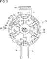
- FIGs. 2 and 3 are each a schematic diagram of a diagnosis system for a hydraulic motor (hydraulic machine) according to one embodiment.
- the hydraulic motor 10 to be diagnosed by the diagnosis system and method includes a rotation shaft 32, a cylinder 20, a piston 22 which forms a working chamber 24 with the cylinder 20, and a high-pressure valve 28 and a low-pressure valve 30 provided for the working chamber 24, and a cam 26 (conversion mechanism) for performing conversion between the reciprocating motion of the piston 22 and the rotational motion of the rotation shaft 32.
- the cam 26 has a cam curved surface configured to contact the piston 22.
- the piston 22 preferably includes a piston body portion 22A which slides inside the cylinder 20, and a piston roller or a piston shoe which is attached to the piston body portion 22A and which contacts the cam curved surface of the cam 26, from the perspective of smoothly converting the reciprocating motion of the piston 22 into the rotational motion of the rotation shaft 32.
- the piston 22 includes a piston body portion 22A and a piston shoe 22B.
- the cam 26 is an eccentric cam disposed eccentrically from the axial center O of the rotation shaft (crank shaft) 32 of the hydraulic motor 10. While the piston 22 performs a set of upward and downward movement, the cam 26 and the rotation shaft 32 to which the cam 26 is mounted perform one revolution.
- the cam 26 is an annular-shaped multi-lobed cam (ring cam) with a plurality of lobes. In this case, while the cam 26 and the rotation shaft 32 to which the cam 26 is mounted perform one revolution, the piston 22 performs as many sets of upward and downward movement as the number of lobes.
- the high-pressure valve 28 is disposed in a high-pressure communication line 34 between the working chamber 24 and the high-pressure line 12 disposed outside the working chamber 24, and configured to be capable of switching the communication state between the working chamber 24 and the high-pressure line 12.
- the low-pressure valve 30 is disposed in a low-pressure communication line 36 between the working chamber 24 and the low-pressure line 14 disposed outside the working chamber 24, and configured to be capable of switching the communication state between the working chamber 24 and the low-pressure line 14.
- a diagnosis system 70 of the hydraulic motor 10 illustrated in FIGs. 2 and 3 includes a monitor/controller 110 for controlling and monitoring the operation state of a device (e.g. the high-pressure valve 28 and the low-pressure valve 30) constituting the hydraulic motor 10, or an instrument (e.g. the pressure sensor 72 described below).
- the monitor/controller 110 includes an abnormality determination part 118 for determining abnormality of the hydraulic motor 10 (hydraulic machine) and a controller 111 for controlling a device constituting the hydraulic motor 10.
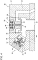
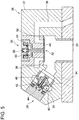
- FIGs. 4 and 5 are each a schematic cross-sectional view of the configuration of the high-pressure valve 28 and the low-pressure valve 30.
- FIG. 4 illustrates a situation where the high-pressure valve 28 is closed and the low-pressure valve 30 is open
- FIG. 5 illustrates a situation where the high-pressure valve 28 is open and the low-pressure valve 30 is closed.
- the high-pressure valve 28, the low-pressure valve 30, and a casing 37 of the valves may be unitized and configured as a valve unit 38, as illustrated in FIGs. 4 and 5 .
- the high-pressure valve 28 and the low-pressure valve 30 are controlled to open and close by a valve control part 112 (see FIG. 3 ) that the controller 111 includes.
- the valve control part 112 controls the opening-closing motion of the high-pressure valve 28 by applying a HPV control signal (opening-closing command for the high-pressure valve 28) to the high-pressure valve 28, and controls the opening-closing motion of the low-pressure valve 30 by applying a LPV control signal (opening-closing command for the low-pressure valve 30) to the low-pressure valve 30.
- the high-pressure valve 28 illustrated in FIGs. 4 and 5 includes a movable unit 40 including a valve body 35, a solenoid coil 42 that functions as an actuator for moving the movable unit 40 between a valve-open position and a valve-closed position, a spring 44, and a valve seat 46.
- the high-pressure valve 28 is a poppet solenoid valve of normally-closed type, with the valve seat 46 disposed on a side adjacent to the working chamber 24 with respect to the valve body 35.
- the high-pressure valve 28 is capable of switching the communication state between the working chamber 24 and the high-pressure line 12 (see FIG. 12) by movement of the movable unit 40 caused by the electromagnetic force of the solenoid coil 42 or the biasing force of the spring 44.
- the movable unit 40 When the high-pressure valve 28 is not excited by the HPV control signal from the valve control part 112, the movable unit 40 is biased toward the valve seat 46 by the spring 44, so as to be retained in a position such that the working chamber 24 and the high-pressure line 12 are not in communication (normal position; the position of the movable unit 40 in FIG. 4 ).
- the movable unit 40 moves to a position such that the working chamber 24 and the high-pressure line 12 communicate with each other by the electromagnetic force, against the biasing force of the spring 44 (excitation position; the position of the movable unit 40 in FIG. 5 ).
- the high-pressure valve 28 is configured such that the valve body is movable by the supply control of the excitation current, between the normal position where the excitation current is not supplied and the excitation position where the excitation current is supplied.
- the low-pressure valve 30 illustrated in FIGs. 4 and 5 includes a movable unit 52 including a valve body 48 and an armature 50, a solenoid coil 54, a spring 56, and a valve seat 58.
- the low-pressure valve 30 is a poppet solenoid valve of normally-open type, with the valve body 48 disposed on the side of the working chamber 24 with respect to the valve seat 58.
- the low-pressure valve 30 is capable of switching the communication state between the working chamber 24 and the low-pressure line 14 (see FIG. 2 ) by movement of the movable unit 52 caused by the electromagnetic force of the solenoid coil 54 or the biasing force of the spring 56.
- the movable unit 52 When the low-pressure valve 30 is not excited by the LPV control signal from the valve control part 112, the movable unit 52 is biased in a direction away from the valve seat 58 by the spring 56, so as to be retained in a valve-open position such that the working chamber 24 and the low-pressure line 14 are in communication with each other (normal position; the position of the movable unit 52 in FIG. 4 ).
- the low-pressure valve 30 When the low-pressure valve 30 is excited by the LPV control signal from the valve control part 112, the electromagnetic force of the solenoid coil 54 attracts the armature 50 and the movable unit 52 moves toward the valve seat 58 by the electromagnetic force against the biasing force of the spring 56, thereby moving to a valve-closed position such that the working chamber 24 and the high-pressure line 12 are not in communication (excitation position; the position of the movable unit 52 in FIG. 5 ).
- the low-pressure valve 30 is configured such that the valve body is movable by the supply control of the excitation current, between the normal position where the excitation current is not supplied and the excitation position where the excitation current is supplied.
- the diagnosis system 70 of the hydraulic motor 10 includes a pressure sensor 72 for measuring a pressure of the working chamber 24.
- the signal representing the pressure of the working chamber 24 measured by the pressure sensor 72 is inputted to the monitor/controller 110.
- the measurement result obtained by the pressure sensor 72 is used by the abnormality determination part 118 to determine abnormality of the hydraulic motor 10.
- the abnormality determination part 118 includes the first abnormality determination part 114 and/or the second abnormality determination part described below.
- a signal representing an electric-current value measured by an electric-current measuring part 74 for measuring a value of the excitation current supplied to the low-pressure valve 30 is inputted to the monitor/controller 110.
- each of the working chambers 24 may include the pressure sensor 72, as illustrated in FIG. 2 .
- the diagnosis system 70 of the hydraulic motor 10 includes the first abnormality determination part 114 for determining abnormality of the hydraulic machine on the basis of the measurement result of the pressure sensor 72.
- the first abnormality determination part 114 determines abnormality of the hydraulic motor 10 on the basis of the measurement result obtained by the pressure sensor 72 when the low-pressure valve 30 is not supplied with the excitation current.
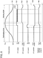
- FIG. 6 is a diagram illustrating the opening-closing motion of the high-pressure valve 28 and the low-pressure valve 30 and a pressure fluctuation inside the working chamber 24 while the cylinder 20 performs an active cycle.
- An active cycle of the hydraulic motor 10 refers to a cycle in which pressurized oil from the hydraulic pump 8 performs a work to rotate the rotation shaft of the hydraulic motor 10 in the cylinder 20, i.e., a cycle in which the displacement of the working oil is generated.
- the piston-cycle curve 130 is a curve representing a time-series change of the position of a piston 22, where the x-axis is time t.
- an HPV control signal 132 represents a control signal to be supplied to the high-pressure valve 28
- a high-pressure valve position 134 represents an open/closed state of the high-pressure valve 28
- an LPV control signal 136 represents a control signal to be supplied to the low-pressure valve 30
- a low-pressure valve position 138 represents an open/closed state of the low-pressure valve 30
- a pressure curve 140 represents a pressure in the working chamber 24.
- the differential pressure between the high-pressure line 12 and the low-pressure line 14 created by the hydraulic pump 8 moves the pistons 22 upward and downward cyclically, so that each piston 22 repeats a discharging stroke of moving toward a top dead center from a bottom dead center and a motoring stroke of moving toward a bottom dead center from a top dead center.
- the HPV control signal 132 is applied to the high-pressure valve 28 of normally-closed type. As represented by the HPV control signal 132 in FIG. 6 , the high-pressure valve 28 is supplied with the excitation current immediately before the piston 22 reaches the top dead center, and thereby the high-pressure valve opens as represented by the high-pressure valve position 134.
- the high-pressure valve 28 opens, the high-pressure fluid flows into the working chamber 24 to rotate the cam 26.
- a biasing force a force acting in a direction to close the high-pressure valve 28
- repeating excitation and de-excitation of the high-pressure valve 28 at a high frequency makes it possible to latch the high-pressure valve 28 in an open state using little current. For instance, a signal having a duty ratio of 20 % and a cycle of 10kHz can be used.
- the pulse control signal given to the high-pressure valve 28 preferably has a higher frequency than that of the reciprocal number of a time constant of the coil of the high-pressure valve 28, from the perspective of securely maintaining the high-pressure valve 28 to be open.
- the final pulse 132A of the high-frequency signal repeating excitation and de-excitation of the high-pressure valve 28 may be regarded as a control signal for switching the high-pressure valve 28 from an open state to a closed state.
- the low-pressure valve 30 of normally-open type the low-pressure valve 30 is excited (closed) immediately before the piston 22 reaches the top dead center, and then the high-pressure valve 28 is excited (opened), so that the low-pressure valve 30 is maintained to be closed by the differential pressure between the opposite sides of the valve body 48.
- the low-pressure valve 30 is closed by being excited immediately before the piston 22 reaches the top dead center.
- the low-pressure valve 30 is maintained to be closed by the differential pressure between the working chamber 24 and the low-pressure line 14 even if the low-pressure valve 30 is closed by excitation and then de-excited before the piston 22 reaches the top dead center, because the pressure in the working chamber 24 is high (see the pressure curve 140) during a period during which the piston 22 moves toward the top dead center (a period in the discharging stroke after the low-pressure valve 98 is closed).
- FIGs. 7A to 7D are each a schematic graph showing a change in the excitation current to the low-pressure valve 30 over time t, and a measurement result (i.e., a change in the pressure inside the working chamber 24, which is a chamber pressure) obtained by the pressure sensor 72 corresponding to the same.
- FIG. 7A illustrates a case in which the cylinder is performing an active cycle while the hydraulic motor 10 is in normal operation.
- FIG. 7B illustrates a case in which the cylinder is performing an inactive cycle while the hydraulic motor 10 is in normal operation. In both of FIGs.
- FIG. 7C illustrates a case in which the self-pumping described below is occurring
- FIG. 7D illustrates a case in which the juddering described below is occurring.
- "low-pressure valve(LPV) current” of y-axis represents the magnitude of the excitation current to the low-pressure valve 30.
- “ON” refers to the excitation current when the excitation current is supplied to the low-pressure valve 30, and “OFF” to that when the excitation current is not supplied.
- chamber pressure of y-axis represents the magnitude of the pressure inside the working chamber 24.
- T BDC1 , t BDC2 , and the like of x-axis represent the time points at which the piston 22 passes through the bottom dead center. Specifically, a period from t BDC1 to t BDC2 and a period from t BDC2 to t BDC3 correspond to a rotational cycle T* of the rotation shaft 32, which is a cycle of the reciprocating motion of the piston 22.
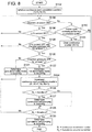
- FIG. 8 is a flowchart illustrating an example of a process for determining abnormality of the hydraulic motor 10 (hydraulic machine) by the first abnormality determination part 114 according to one embodiment.
- "chamber pressure ON” refers to when the chamber pressure is at least a threshold
- "chamber pressure OFF” to when the chamber pressure is less than the threshold
- "low-pressure valve (LPV) current OFF” to when the excitation current to the low-pressure valve 30 is at most a threshold.
- the high-pressure valve 28 and the low-pressure valve 30 are repetitively excited and de-excited in relation to the reciprocating cycle of the piston 22, so that the pressure inside the working chamber 24 changes cyclically.
- the cyclic change of the excitation current to the low-pressure valve 30 and the chamber pressure is, for instance, as illustrated in FIG. 7A .
- the high-pressure valve 28 and the low-pressure valve 30 are both in a de-excited state, in which the high-pressure valve 28 is constantly closed and the low-pressure valve 30 is constantly open, so that the working chamber 24 is in communication with the low-pressure line 14.
- the pressure inside the working chamber 24 is relatively low (which may be substantially the same as the pressure of the low-pressure line 14) throughout a cycle (the rotation cycle of the rotation shaft 32) of the cylinder 20.
- the change of the excitation current to the low-pressure valve 30 and the chamber pressure is, for instance, as illustrated in FIG. 7B .
- the excitation current to the low-pressure valve 30 is constantly OFF and the chamber pressure is also constantly OFF throughout the cycle of the cylinder 20.
- the low-pressure valve 30 may close unintentionally due to some reason even if the low-pressure valve 30 is de-excited, and the chamber pressure may increase as shown in the graph of FIG. 7C , which is a phenomenon called self pumping.
- self pumping occurs in the hydraulic motor 10
- the performance of the hydraulic motor 10 may decrease, or the low-pressure valve 30 may get damaged.
- the first abnormality determination part 114 measures a period t 1 during which the pressure of the working chamber 24 is at least the second threshold P th2 (see S104 in FIG. 8 ) in a period during which the excitation current to the low-pressure valve 30 is at most the first threshold I th1 (see S106 of FIG. 8 ) and the rotation shaft 32 performs one revolution (period T* in FIG. 7 ). Then, if the period t 1 continues for at least a predetermined period T 1 (Yes in S108 of FIG.
- the first threshold I th1 of the excitation current may be a mean value of the current value of when the excitation current is ON and the mean value of when the excitation current is OFF.
- the second threshold P th2 of the pressure of the working chamber 24 may be a mean value of the pressure of when the chamber pressure is ON and the pressure of when the chamber pressure is OFF.
- the length of the period t 1 during which the chamber pressure is at least the second threshold P th2 (the chamber pressure is ON) may be obtained on the basis of the increase time point and the decrease time point of the chamber pressure.
- the period t 1 may be from the increase-starting time point t up to the decrease-starting time point t down of the chamber pressure (see FIG. 7C ).
- the period t 1 may be from an increase-ending time point to a decrease-ending time point of the chamber pressure (not illustrated).
- the period from the increase time point to the decrease time point of the chamber pressure may be regarded to have the length of the period t 1 during which the chamber pressure is at least a threshold (chamber pressure is ON).
- a relative phase time axis
- a relative phase is used as a basis of a period during which the chamber pressure is ON during one revolution of the rotation shaft 32, instead of an absolute phase (rotational angle) of the rotation shaft. In this way, it is no longer necessary to take into account inconvenient matters such as an error like a phase error which may occur in a rotation-pulse sensor for measuring the rotation angle.
- the first abnormality determination part 114 after determining whether there is abnormality in the hydraulic motor 10 on the basis of the length t 1 of the period during which the chamber pressure is at least the second threshold P th2 (the chamber pressure is ON) as described above, the first abnormality determination part 114 measures a period t 2 during which the pressure inside the working chamber 24 is at most the third threshold P th3 (the chamber pressure is OFF) during one revolution of the rotation shaft 32 of the hydraulic motor 10. Then, on the basis of whether the above period t 2 continues for at least the predetermined period T 2 , the first abnormality determination part 114 determines the abnormality mode of the hydraulic machine (see S120 in FIG. 8 ).
- the first abnormality determination part 114 determines that the second abnormality mode (juddering; see FIG. 7D ) in which the low-pressure valve fails to open due to a delay in the closing timing of the high-pressure valve, if the period t 2 does not continue for at least the predetermined period T 2 . Further, the first abnormality determination part 114 determines that the first abnormality mode (the above described self pumping; see FIG. 7C ) in which the low-pressure valve opens as the high-pressure valve closes at an appropriate timing but the valve body of the low-pressure valve closes even when the low-pressure valve is not supplied with the excitation current, if the period t 2 continues for at least the predetermined period T 2 (see S120 of FIG. 8 ).
- Juddering is a phenomenon that occurs during an active cycle of the cylinder 20, in which the high-pressure valve 28 does not close normally in the vicinity of the bottom dead center of the piston 22 and thus the low-pressure valve 30 fails to open even though being de-excited, so that the pressure inside the working chamber 24 is high in most time of the rotational cycle of the rotation shaft 32.
- the juddering illustrated in FIG. 7D is intermittent juddering, in which the high-pressure valve 28 closes at a timing later than a predetermined timing, and thereby the piston 22 reaches the bottom dead center while the low-pressure valve 30 cannot open even when de-excited due to a fluid pressure differential applied to either side of the valve body 48.
- the period during which the chamber pressure is at least the second threshold P th2 (the chamber pressure is ON) is longer when the intermittent juddering is occurring than when the operation is normal as illustrated in FIG. 7A .
- juddering called “continuous juddering” may also occur, in which the valve body 35 becomes immovable due to sticking of the movable unit 40 of the high-pressure valve 28 or entry of foreign matters, so that the high-pressure valve 28 fails to close and continues to be open during the entire period of the reciprocating motion of the piston 22.
- the period during which the chamber pressure is at least the second threshold P th2 (the chamber pressure is ON) is remarkably longer when the continuous juddering is occurring than when the operation is normal as illustrated in FIG. 7A .
- the chamber pressure may decrease rapidly and then immediately increase, as indicated by arrow "A" in FIG. 7D .
- an event may occur, in which the period t 1 during which the pressure of the working chamber 24 is at least the second threshold P th2 continues for at least the predetermined period T 1 in a period (period T* in FIG. 7 ) during which the excitation current to the low-pressure valve 30 is at most the first threshold I th1 and the rotation shaft 32 performs one revolution.
- the period t 1 continues for at least the predetermined period T 1 , there is a risk of wrongly determining that the above described "self pumping" event is occurring.
- Self pumping and juddering are similar in that the low-pressure valve is kept closed unintentionally and the chamber pressure is high.
- the cause of the self-pumping is malfunction of the operation of the low-pressure valve
- the cause of the juddering is malfunction of the operation of the high-pressure valve. Since the two phenomena are caused by different mechanisms, it is desirable to be able to determine which phenomenon of self pumping (the first abnormality mode) or juddering (the second abnormality mode) is occurring, in order to determine abnormality of the hydraulic motor 10 appropriately.
- Self pumping occurs after occurrence of an event in which the high-pressure valve 28 closes just before the piston 22 moves to reach the bottom dead center from the top dead center so that the volume of the working chamber expands to decrease the chamber pressure and the low-pressure valve 30 is open.
- the chamber pressure is low (OFF) for a predetermined period in the reciprocating cycle of the piston 22. Therefore, on the basis of T 2 satisfying the above relationship, it is possible to determine whether the current abnormality event is self-pumping.
- abnormality self pumping
- the accuracy of the abnormality determination may be low.
- abnormality self pumping
- the first abnormality determination part 114 determines that abnormality is occurring in the hydraulic motor 10, if the continuous occurrence number N 1 of an event exceeds a threshold, the event being such that the period t 1 during which the pressure of the working chamber 24 is at least the second threshold P th2 continues for at least the predetermined period T 1 , in a period (period of length T*) during which the excitation current to the low-pressure valve 30 is at most the first threshold I th1 and the rotation shaft 32 performs one revolution (see Yes in S126 and S127 of FIG. 8 ).
- the number of continuous occurrence is the number of cycles in which the above event occurs continuously in the cylinder cycles repeated more than once.
- the first abnormality determination part 114 determines that abnormality is occurring in the hydraulic motor 10, if the cumulative occurrence number N 2 of an event exceeds a threshold, the event being such that the period t 1 during which the pressure of the working chamber 24 is at least the second threshold P th2 continues for at least the predetermined period T 1 , in a period (period of length T*) during which the excitation current to the low-pressure valve 30 is at most the first threshold I th1 and the rotation shaft 32 performs one revolution (see Yes in S128 and S130 of FIG. 8 ).
- the number of cumulative occurrence is the number of cycles in which the above event occurs, among the cylinder cycles repeated more than once. The number of cycles is counted also including non-successive cycles with the above event.
- the ratio of cycles in which the low-pressure valve 30 is supplied with the excitation current (active cycles) during one revolution of the rotation shaft 32 of the hydraulic motor 10 (hydraulic machine) is greater.
- the ratio of cycles in which one cylinder 20 stops supplying the excitation current to the low-pressure valve 30 continuously (inactive cycles) is small.
- the above described event is detected in a plurality of discontinuous (non-successive) cycles, and there is a low possibility of detecting the event in more than one cycle successively.
- it is difficult to determine abnormality on the basis of the continuous occurrence number N 1 it is difficult to determine abnormality on the basis of the continuous occurrence number N 1 , and it is suitable to determine abnormality on the basis of the cumulative occurrence number N 2 .
- the ratio of cycles in which the low-pressure valve 30 is not supplied with the excitation current (inactive cycles) during one revolution of the rotation shaft 32 of the hydraulic motor 10 (hydraulic machine) is greater.
- inactive cycles may be continuously performed by one working chamber.
- the first abnormality determination part 114 compares the continuous occurrence number N 1 of the event to a threshold (see S126 of FIG. 8 ), and if the continuous occurrence number N 1 is greater than the threshold (Yes in S126 of FIG. 8 ), determines that continuous self pumping (abnormality of the hydraulic motor 10) is occurring (see S127 of FIG. 8 ). Further, the first abnormality determination part 114 compares the cumulative occurrence number N 2 of the event to a threshold (see S128 of FIG. 8 ), and if the cumulative occurrence number N 2 is greater than the threshold (Yes in S128 of FIG. 8 ), determines that cumulative self pumping (abnormality of the hydraulic motor 10) is occurring (see S130 of FIG. 8 ).
- the relationship between the cumulative occurrence number N 2 and the continuous occurrence number N 1 may be represented by N 2 > N 1 . While it is possible to determine abnormality on the basis of the cumulative occurrence number N 2 during low-load operation of the hydraulic motor 10 (hydraulic machine), setting the continuous occurrence number N 1 to be smaller than the cumulative occurrence number N 2 makes it possible to determine occurrence of abnormality in the hydraulic motor 10 more quickly by using the continuous occurrence number N 1 as a determination basis during low-load operation of the hydraulic motor 10.
- the first abnormality determination part 114 includes a continuous counter and a cumulative counter for counting the continuous occurrence number N 1 and the cumulative occurrence number N 2 .
- the first abnormality determination part 114 firstly clears the count of each of the continuous counter and the cumulative counter to set the continuous occurrence number N 1 and the cumulative occurrence number N 2 to zero (S102 in FIG. 8 ). Then, the first abnormality determination part 114 performs the determination of the series of steps S104 to S 120 in FIG. 8 . If the chamber pressure does not reach a threshold or higher in S104 (No in S104), the procedure proceeds as follows.
- the first abnormality determination part 114 determines that there is no such abnormality that increases the pressure at an intended timing in the cylinder, clears the count (the continuous occurrence number N 1 ) of the continuous counter (see S105 of FIG. 8 ), and returns to step S104, then advancing to detection of self pumping in the next cylinder cycle (S104 to S120).
- the first abnormality determination part 114 returns to step S104 without clearing the continuous counter, and continues detection of abnormality (self pumping) in the same cylinder.
- each count (the continuous occurrence number N 1 and the cumulative occurrence number N 2 ) is incremented for the continuous counter and the cumulative counter (S124 in FIG. 8 ). Then, occurrence of self pumping is determined on the basis of the continuous occurrence number N 1 and the cumulative occurrence number N 2 (S216 and S218 in FIG. 8 ), and if occurrence of self pumping is not determined as a result (No in S128), the procedure returns to step S104, and advances to detection of self pumping in the next cylinder cycle (S104 to S120).
- the abnormality determination flow may be stopped temporarily, and the continuous counter and the cumulative counter may be cleared (initialized). Then, after the rotation speed of the hydraulic motor 10 having returned to at least the threshold, the execution of the abnormality determination flow illustrated in FIG. 8 may be started again.
- the diagnosis system 70 of the hydraulic motor 10 further includes the second abnormality determination part 116 for determining abnormality of the hydraulic machine on the basis of the measurement result of the pressure sensor 72, in addition to the first abnormality determination part 114.
- the second abnormality determination part 116 shifts the supply-start timing or the supply-stop timing of the excitation current to at least one of the high-pressure valve 28 or the low-pressure valve 30 in a predetermined range, and determines abnormality of the hydraulic motor 10 (hydraulic machine) on the basis of an influence of the supply-start timing or the supply-stop timing on the pressure of the working chamber 24.
- the second abnormality determination part 116 determines abnormality of the hydraulic motor 10 on the basis of the manner of a pressure change of the working chamber 24 at the time when the supply-start timing of the excitation current to the low-pressure valve 30 is retarded to a limit of the predetermined range toward the point of time when the piston 22 reaches the top dead center.
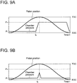
- FIG. 9A is a graph showing a change in the chamber pressure during normal operation of the hydraulic motor
- FIG. 9B is a graph showing a change in the chamber pressure when there is the latch failure described below in the hydraulic motor.
- the low-pressure valve 30 in the active cycle during normal operation of the hydraulic motor 10 (hydraulic machine), the low-pressure valve 30 is supplied with excitation current to be closed before the piston 22 reaches the top dead center, and then (from time t a in FIG. 9A ) the high-pressure valve 28 becomes openable as the pressure of the working chamber 24 increases due to the piston 22 moving toward the top dead center.
- P H in FIGs. 9A and 9B represents the pressure in the high-pressure line 12
- P L represents the pressure in the low-pressure line 14.
- the high-pressure valve 28 and the low-pressure valve 30 are normal, it is possible to intentionally cause the above latch fail by retarding the supply-start timing of the excitation current to the low-pressure valve 30.
- the latch failure does not occur even if the supply-start timing of the excitation current to the low-pressure valve 30 is retarded, because the low-pressure valve 30 closes before the piston 22 passes through the top dead center, which increases the chamber pressure and opens the high-pressure valve 28.
- the second abnormality determination part 116 it is possible to detect self pumping on the basis of whether latch failure is occurring. Further, it is possible to improve the reliability of the abnormality determination for the hydraulic motor 10 (hydraulic machine) by detecting self pumping in each abnormality determination part using both of the first abnormality determination part 114 and the second abnormality determination part 116.
- the wind turbine power generating apparatus 1 includes a pitch drive (pitch drive device) 60 for adjusting the pitch angle of the at least one blade 2.
- the controller 111 includes a pitch control part 113 which controls the hydraulic motor 10 so as to reduce the displacement of the hydraulic motor 10 and controls the pitch drive 60 so as to reduce the wind energy to be extracted by the at least one blade 2, if the first abnormality determination part 114 of the diagnosis system 70 detects abnormality of the hydraulic motor 10.
- the displacement of the hydraulic motor 10 having the above configuration depends on the ratio of cylinders 20 performing the active cycle or the inactive cycle among a plurality of cylinders 20 constituting the hydraulic motor 10.
- the ratio of the cylinders 20 performing the inactive cycle among all cylinders 20 of the hydraulic motor 10 is to be increased.
- the valve control part 112 may control the high-pressure valve 28 to be kept closed and the low-pressure valve 30 to be kept open, during a cycle in which the piston 22 starts the bottom dead center and returns to the same via the top dead center so as not to increase the pressure of the working oil, thereby causing some cylinders 20 to perform the inactive cycle.
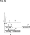
- FIG. 10 is a configuration example of a pitch drive.
- the pitch drive 60 illustrated in FIG. 10 includes a hydraulic cylinder 62, a servo valve 64, a hydraulic source 66 and an accumulator 68, and is accommodated in a hub for housing the hydraulic transmission 7 and the like of the wind turbine power generating apparatus 1 illustrated in FIG. 1 .
- the servo valve 64 adjusts, under the control of the pitch control part 113, the amount of high-pressure oil to be supplied to the hydraulic cylinder 62, the high pressure oil including high-pressure oil generated by the hydraulic source 66 and high-pressure oil stored in the accumulator 68, so as to achieve a desired pitch angle of the at least one blade 2.
- the pitch drive 60 is controlled by the pitch control part 113 to adjust the pitch angle of the at least one blade 2 and decrease the rotation speed of the rotor 3, thereby reducing the rotation speed of the hydraulic pump 8.
- the rotation speed of the hydraulic pump 8 and/or the hydraulic motor 10 is reduced by decreasing the displacement of the hydraulic pump 8 and/or the hydraulic motor 10, while the pitch drive 60 is used to apply an aerodynamic braking force to the rotor 3 to reduce the rotation speed of the hydraulic pump 8. In this way, it is possible to reduce the wind energy to be extracted by the at least one blade 2.
- the displacement of the hydraulic motor 10 is not reduced to zero at once, but is gradually decreased, which makes it possible to stop the wind turbine power generating apparatus 1 while protecting the constituent members (e.g. the high-pressure valve 28 and the low-pressure valve 30) of the hydraulic motor 10.
- an expression of relative or absolute arrangement such as “in a direction”, “along a direction”, “parallel”, “orthogonal”, “centered”, “concentric” and “coaxial” shall not be construed as indicating only the arrangement in a strict literal sense, but also includes a state where the arrangement is relatively displaced by a tolerance, or by an angle or a distance whereby it is possible to achieve the same function.
- an expression of an equal state such as “same” “equal” and “uniform” shall not be construed as indicating only the state in which the feature is strictly equal, but also includes a state in which there is a tolerance or a difference that can still achieve the same function.
- an expression of a shape such as a rectangular shape or a cylindrical shape shall not be construed as only the geometrically strict shape, but also includes a shape with unevenness or chamfered corners within the range in which the same effect can be achieved.
- an expression such as “comprise”, “include”, “have”, “contain” and “constitute” are not intended to be exclusive of other components.
Landscapes
- Engineering & Computer Science (AREA)
- Mechanical Engineering (AREA)
- General Engineering & Computer Science (AREA)
- Combustion & Propulsion (AREA)
- Chemical & Material Sciences (AREA)
- Life Sciences & Earth Sciences (AREA)
- Sustainable Development (AREA)
- Sustainable Energy (AREA)
- Power Engineering (AREA)
- Wind Motors (AREA)
- Testing Of Devices, Machine Parts, Or Other Structures Thereof (AREA)
- Fluid-Pressure Circuits (AREA)
- Control Of Positive-Displacement Pumps (AREA)
Abstract
Description
- The present disclosure relates to a diagnosis system for a hydraulic machine, a hydraulic machine, a wind turbine power generating apparatus, and a method of diagnosing a hydraulic machine.
- A hydraulic machine such as a hydraulic pump and a hydraulic motor is conventionally known.
For instance,Patent Document 1 describes a hydraulic machine which performs conversion between fluid energy of working fluid and rotational energy of a rotation shaft, utilizing a cyclic volume change of a working chamber formed by a cylinder and a piston. - Further,
Patent Document 2 describes an approach for suppressing occurrence of abnormality in opening and closing of a valve for switching a communication state between a working chamber of a hydraulic machine and outside of the working chamber, which is to control an opening-closing timing of the valve in accordance with the characteristics of the constituent members of a fluid working machine or a state of working fluid (working oil). -
- Patent Document 1:
US 2010/0040470A - Patent Document 2:
WO2011/104547A - In a hydraulic machine such as a hydraulic pump and a hydraulic motor, if abnormality (e.g. abnormality of the opening-closing timing of a valve) of the hydraulic machine occurs, the abnormality may cause deterioration in the performance of the hydraulic machine or damage to each part (e.g. valve) of the hydraulic machine.
To prevent such problems in advance, it is important to detect abnormality in the hydraulic machine before occurrence of deterioration in the performance of the hydraulic machine or damage to each part of the hydraulic machine.
In this regard,Patent Documents - In view of the above issue, an object of at least one embodiment of the present invention is to provide a diagnosis system for a hydraulic machine, a hydraulic machine, a wind turbine power generating apparatus, and a method of diagnosing a hydraulic machine whereby it is possible to diagnose abnormality of the hydraulic machine precisely.
- (1) A diagnosis system for a hydraulic machine according to at least one embodiment of the present invention is for a hydraulic machine including a rotation shaft, a cylinder, a piston forming a working chamber together with the cylinder, and a high-pressure valve and a low-pressure valve provided for the working chamber, the hydraulic machine being configured to perform conversion between rotational motion of the rotation shaft and reciprocating motion of the piston. The diagnosis system comprises: a pressure sensor for measuring a pressure in the working chamber; and a first abnormality determination part for determining an abnormality of the hydraulic machine on the basis of a measurement result obtained by the pressure sensor. At least one valve between the high-pressure valve and the low-pressure valve is configured such that a valve body is movable, by supply control of excitation current, between a normal position at which the at least one valve is not supplied with the excitation current and an excitation position at which the at least one valve is supplied with the excitation current, and the first abnormality determination part is configured to determine an abnormality of the hydraulic machine on the basis of the measurement result obtained by the pressure sensor when the at least one valve is not supplied with the excitation current.
A pressure in a working chamber (hereinafter, also referred to as "chamber pressure") changes in accordance with opening and closing of the high-pressure valve and the low-pressure valve, and with the reciprocating motion of the piston. Thus, the chamber pressure fluctuates cyclically during normal operation of a hydraulic machine. The cyclic change of the chamber pressure is achieved by controlling the high-pressure valve or the low-pressure valve. Specifically, in a case where the high-pressure valve or the low-pressure valve is a valve in which the position of a valve body is controlled to switch between a normal position (open position or closed position) and an excitation position by supply control of excitation current, the chamber pressure fluctuates cyclically by controlling the supply of the excitation current to open or close the valve so that the hydraulic machine performs required motion.
In this case, when the high-pressure valve or the low-pressure valve is not supplied with the excitation current, the valve body is normally at the normal position due to a biasing force applied to the valve body. However, if a force in a direction opposite to that of the biasing force acts on the valve body due to some reason, a phenomenon such that valve body gets fixed to the excitation position even when not supplied with the excitation current may occur. If the motion of the valve is different from desired motion as described above, the pressure in the working chamber changes in a manner different from the above described cyclic pressure fluctuation. Thus, when the high-pressure valve or the low-pressure valve is not supplied with the excitation current and if the pressure in the working chamber has a manner different from that in normal operation, it may be considered that abnormality is occurring in the hydraulic machine.
With the above diagnosis system (1), since it is possible to determine abnormality of the hydraulic machine on the basis of a measurement result obtained by the pressure sensor when the high-pressure valve or the low-pressure valve is not supplied with the excitation current using the first abnormality determination part, it is possible to diagnose abnormality of the high-pressure valve precisely. - (2) In some embodiments, in the above configuration (1), the low-pressure valve is a normally-open solenoid valve configured to be open when the low-pressure valve is not supplied with the excitation current and the valve body is at the normal position, and the first abnormality determination part is configured to detect an abnormality of the hydraulic machine on the basis of whether a period during which the pressure in the working chamber is at least a second threshold continues for at least a predetermined period T1 while the excitation current supplied to the low-pressure valve is at most a first threshold and during one revolution of the rotation shaft.
If the low-pressure valve that should be normally open closes due to some reason while the low-pressure valve, which is a solenoid valve of normally-open type, is not supplied with excitation current (during non-supply time), the pressure in the working pressure increases because the low-pressure line and the working chamber are not in communication in a period during which the low-pressure valve should normally open so that the low-pressure line and the working chamber are in communication.
With the above configuration (2), it is possible to detect abnormality of a hydraulic machine precisely on the basis of whether a period during which the excitation current to the low-pressure valve is at most the first threshold ("non-supply time" of the excitation current) and the pressure in the working chamber is at least a second threshold (the working chamber has a relatively high pressure) continues for at least a predetermined period T1. - (3) In some embodiments, in the above configuration (1), the predetermined period T1 satisfies a relationship represented by 0.15T* ≤ T1 ≤ 0.25T*, where T* = 60/ωrated, and ωrated is a rated rotation speed (rpm) of the hydraulic machine.
The inventors found that abnormality is occurring in the hydraulic machine when the excitation current to the low-pressure valve is at most the first threshold (non-supply time) and a period during which the pressure in the working chamber is at least the second threshold (a period during which the working chamber has a relatively high pressure) continues for at least a period T1 satisfying a relationship represented by 0.15T* ≤ T1 ≤ 0.25T* where T* is a rotation cycle at a rated rotation speed ω of the hydraulic machine. With the above configuration (3), it is possible to detect abnormality of the hydraulic machine on the basis of the predetermined period T1 satisfying a relationship represented by 0.15T* ≤ T1 ≤ 0.25T* where T* is a rotation cycle at a rated rotation speed ω of the hydraulic machine. - (4) In some embodiments, in the above configuration (2) or (3), the first abnormality determination part is configured to obtain a length of a period during which the pressure in the working chamber is at least the second threshold, on the basis of an increase time point and a decrease time point of the pressure in the working chamber..
In the above configuration (4), the length of the period during which the pressure in the working chamber is relatively high is obtained on the basis of the increase time point and the decrease time point of the pressure. Thus, a revolution indicator is unnecessary, unlike a case where the length of the period during which the pressure in the working chamber is relatively high is obtained on the basis of an absolute phase (rotation angle) of the rotation shaft. Further, since a revolution indicator is unnecessary, it is not necessary to take into account a trouble such as an error of a revolution indicator. Thus, with the above configuration (4), it is possible to detect abnormality of the hydraulic machine easily and accurately. - (5) In some embodiments, in any of the above configurations (1) to (4), the first abnormality determination part is configured to determine an abnormality mode from among a plurality of abnormality modes of the hydraulic machine on the basis of whether a period during which the pressure in the working chamber is at most a third threshold continues for at least a predetermined time T2 during one revolution of the rotation shaft.
Among a plurality of abnormality modes of the hydraulic machine the pressure in the working chamber may have a similar manner when the hydraulic machine or the low-pressure valve is not supplied with excitation current. For instance, the pressure in the working chamber may increase when the low-pressure valve, which is a normally-open solenoid valve, is not supplied with excitation current, due to a failure of the low-pressure valve and also due to a failure of the high-pressure valve. The above two cases are different in the length of the period during which the working chamber has a relatively low pressure during one revolution of the rotation shaft.
With the above configuration (5), it is possible to determine an abnormality mode of the hydraulic machine precisely on the basis of whether a period during which the pressure in the working chamber is at most the third threshold (the working chamber has a relatively low pressure) during one revolution of the rotation shaft continues for at least the predetermined time T2, before period in which a period during which the excitation current to the low-pressure valve is at most the first threshold and the pressure in the working chamber is at least the second threshold during one revolution of the rotation shaft continues for the predetermined period T1, for instance. - (6) In some embodiments, in the above configuration (5), the high-pressure valve is a normally-closed solenoid valve, the low-pressure valve is a normally-open solenoid valve, and the first abnormality determination part is configured to determine whether the abnormality mode of the hydraulic machine is a second abnormality mode in which the low-pressure valve fails to open due to a delay in a closing timing of the high-pressure valve, or a first abnormality mode in which the low-pressure valve opens due to a closure of the high-pressure valve at an appropriate timing, but the valve body of the low-pressure valve closes even when the low-pressure valve is not supplied with the excitation current.
With the above configuration (6), it is possible to determine different abnormality modes on the basis of a measurement result obtained by the pressure sensor when at least one of the high-pressure valve or the low-pressure valve is not supplied with the excitation current. - (7) In some embodiments, in the above configuration (5) or (6), the predetermined period T2 satisfies a relationship represented by 0.25T* ≤ T2 ≤ 0.45T*, where T* = 60/ωrated, and ωrated is a rated rotation speed (rpm) of the hydraulic machine.
The inventors found that the above first abnormality mode is occurring when a period during which the pressure in the working chamber is at most the third threshold (a period during which the working chamber has a relatively low pressure) continues for at least a period T2 satisfying a relationship represented by 0.25T* ≤ T2 ≤ 0.45T* where T* at a rated rotation speed ω of the hydraulic machine, during one revolution of the rotation shaft. With the above configuration (7), it is possible to determine different abnormality modes precisely on the basis of the period T2 satisfying a relationship represented by 0.25T* ≤ T2 ≤ 0.45T* where T* is a rotation cycle at a rated rotation speed ω of the hydraulic machine. - (8) In some embodiments, in any one of the above configurations (1) to (7), the diagnosis system for a hydraulic machine further comprises a second abnormality determination part configured to shift a supply-start timing or a supply-stop timing of the excitation current supplied to the at least one valve within a predetermined range, and to determine an abnormality of the hydraulic machine on the basis of an influence of the supply-start timing or the supply-halt timing on the pressure in the working chamber.
When the supply-start timing or the supply-stop timing of the excitation current to the high-pressure valve or the low-pressure valve is shifted, the opening-closing manner of the high-pressure valve or the low-pressure valve should change, and the manner of the chamber pressure should also change. The principle of the above configuration (8) for determining abnormality is based on this premise.
That is, in the above configuration (8), with the predetermined range of the supply-start timing or the supply-stop timing of the excitation current set within a range such that a predetermined change appears in a manner of the chamber pressure, it is possible to determine abnormality of the hydraulic machine on the basis of whether the manner of the chamber pressure shows a predicted change when the supply-start timing or the supply-stop timing of the excitation current is shifted in the predetermined range. In this case, it is possible to determine that abnormality of the hydraulic machine is occurring if the manner of the chamber pressure does not show a predicted change even if the supply-start timing or the supply-stop timing of the excitation current to the high-pressure valve or the low-pressure valve is shifted within a predetermined range.
With the above configuration (8), it is possible to detect abnormality of the hydraulic machine by both of the first abnormality determination part and the second abnormality determination part, which improves the reliability of the abnormality determination of the hydraulic machine. - (9) In some embodiments, in the above configuration (8), the high-pressure valve is a normally-closed solenoid valve, the low-pressure valve is a normally-open solenoid valve, and the second abnormality determination part is configured to determine an abnormality of the hydraulic machine on the basis of a manner of a change in the pressure in the working chamber at the time when the supply-start timing of the excitation current to the low-pressure valve is retarded to a limit of the predetermined range toward a point of time at which the piston reaches the top dead center.
When the supply-start timing of the excitation current to the low-pressure valve is shifted, the opening-closing manner of the low-pressure valve should change, and the manner of the chamber pressure should also change. The principle of the above configuration (9) for determining abnormality is based on this premise.
That is, in the above configuration (9), with the predetermined range of the supply-start timing of the excitation current set within a range such that a predetermined change appears in a manner of the chamber pressure, it is possible to determine abnormality of the hydraulic machine on the basis of whether the manner of the chamber pressure shows a predicted change when the supply-start timing of the excitation current is shifted in the predetermined range. In this case, it is possible to determine that abnormality of the hydraulic machine is occurring if the manner of the chamber pressure does not show a predicted change even if the supply-start timing of the excitation current to the low-pressure valve is shifted within a predetermined range. - (10) In some embodiments, in any of the above configurations (1) to (9), the low-pressure valve is a normally-open solenoid valve configured to open when the low-pressure valve is not supplied with the excitation current and the valve body is at the normal position. The first abnormality determination part is configured to determine that an abnormality is occurring in the hydraulic machine when a continuous occurrence number N1 or a cumulative occurrence number N2 (where N2 > N1) of an event is greater than a threshold, the event being such that the period during which the pressure in the working chamber is at least the second threshold continues for at least the predetermined period T1 while the excitation current to the low-pressure valve is at most the first threshold and during one revolution of the rotation shaft.
With the above configuration (10), it is possible to detect abnormality of the hydraulic machine effectively in both of low-load operation and high-load operation of the hydraulic machine by using the more advantageous determination basis from among the continuous occurrence number N1 and the cumulative occurrence number N2, in accordance with the load state of the hydraulic machine. - (11) A hydraulic machine according to at least one embodiment of the present invention comprises the diagnosis system with the configuration according to any one of the above (1) to (10).
A pressure in a working chamber (chamber pressure) changes in accordance with opening and closing of the high-pressure valve and the low-pressure valve, and with the reciprocating motion of the piston. Thus, a chamber pressure fluctuates cyclically during normal operation of a hydraulic machine. The cyclic change of the chamber pressure is achieved by controlling the high-pressure valve or the low-pressure valve. Specifically, in a case where the high-pressure valve or the low-pressure valve is a valve in which the position of a valve body is controlled to switch between a normal position (open position or closed position) and an excitation position by a supply control of excitation current, the chamber pressure fluctuates cyclically by controlling the supply of the excitation current to open or close the valve so that the hydraulic machine performs required motion.
In this case, when the high-pressure valve or the low-pressure valve is not supplied with the excitation current (non-supply time), the valve body is normally at the normal position due to a biasing force applied to the valve body. However, if a force in a direction opposite to that of the biasing force acts on the valve body due to some reason, a phenomenon such that valve body gets fixed to the excitation position even when not supplied with the excitation current may occur. If the motion of the valve is different from desired motion, the pressure in the working chamber changes in a manner different from the above described cyclic pressure fluctuation. Thus, when the high-pressure valve or the low-pressure valve is not supplied with the excitation current and if the pressure in the working chamber has a manner different from that in normal operation, it may be considered that abnormality is occurring in the hydraulic machine.
With the above configuration (11), since it is possible to determine abnormality of the hydraulic machine on the basis of a measurement result obtained by the pressure sensor when at least one of the high-pressure valve or the low-pressure valve is not supplied with the excitation current using the first abnormality determination part, it is possible to diagnose abnormality of the high-pressure valve precisely. - (12) A wind turbine power generating apparatus according to at least one embodiment of the present invention comprises: a rotor configured to rotate by receiving wind; a hydraulic pump configured to be driven by the rotor to generate pressurized oil; and a hydraulic motor driven by the pressurized oil. At least one of the hydraulic pump or the hydraulic motor comprises the hydraulic machine having the configuration according to the above (11).
A pressure in a working chamber (chamber pressure) changes in accordance with opening and closing of the high-pressure valve and the low-pressure valve, and with the reciprocating motion of the piston. Thus, a chamber pressure fluctuates cyclically during normal operation of a hydraulic machine. The cyclic change of the chamber pressure is achieved by controlling the high-pressure valve or the low-pressure valve. Specifically, in a case where the high-pressure valve or the low-pressure valve is a valve in which the position of a valve body is controlled to switch between a normal position (open position or closed position) and an excitation position by supply control of excitation current, the chamber pressure fluctuates cyclically by controlling the supply of the excitation current to open or close the valve so that the hydraulic machine performs required motion.
In this case, when the high-pressure valve or the low-pressure valve is not supplied with the excitation current, the valve body is normally at the normal position due to a biasing force applied to the valve body. However, if a force in a direction opposite to that of the biasing force acts on the valve body due to some reason, a phenomenon such that valve body gets fixed to the excitation position even when not supplied with the excitation current may occur. If the motion of the valve is different from desired motion, the pressure in the working chamber changes in a manner different from the above described cyclic pressure fluctuation. Thus, when the high-pressure valve or the low-pressure valve is not supplied with the excitation current and if the pressure in the working chamber has a manner different from that in normal operation, it may be considered that abnormality is occurring in the hydraulic machine,.
With the above configuration (12), since it is possible to determine abnormality of the hydraulic machine on the basis of a measurement result obtained by the pressure sensor when the high-pressure valve or the low-pressure valve is not supplied with the excitation current using the fist abnormality determination part, it is possible to diagnose abnormality of the high-pressure valve precisely. - (13) In some embodiments, in the above configuration (12), the rotor includes a hub and at least one blade mounted to the hub, and the wind turbine power generating apparatus further comprises: a pitch drive for adjusting a pitch angle of the at least one blade; and a controller configured to control the hydraulic machine so that a displacement of the hydraulic machine decreases and control the pitch drive so that wind energy to be extracted by the at least one blade decreases, if the first abnormality determination part detects an abnormality of the hydraulic machine.
With the above configuration (13), the displacement of the hydraulic machine is gradually decreased as compared to a case where it is reduced to zero at once, which makes it possible to stop the wind turbine power generating apparatus while protecting the constituent members (e.g. the valves) of the hydraulic machine. - (14) A method of diagnosing a hydraulic machine according to at least one embodiment of the present invention is for a hydraulic machine including a rotation shaft, a cylinder, a piston forming a working chamber together with the cylinder, and a high-pressure valve and a low-pressure valve provided for the working chamber, the hydraulic machine being configured to perform conversion between rotational motion of the rotation shaft and reciprocating motion of the piston. The method comprises: a pressure-measuring step of measuring a pressure in the working chamber; and a first abnormality determination step of determining an abnormality of the hydraulic machine on the basis of a measurement result obtained in the pressure-measuring step. At least one valve between the high-pressure valve and the low-pressure valve is configured such that a valve body is movable, by supply control of excitation current, between a normal position at which the at least one valve is not supplied with the excitation current and an excitation position at which the at least one valve is supplied with the excitation current. The first abnormality determination step comprises determining an abnormality of the hydraulic machine on the basis of the measurement result obtained in the pressure-measuring step when the at least one valve is not supplied with the excitation current.
- A pressure in a working chamber (chamber pressure) changes in accordance with opening and closing of the high-pressure valve and the low-pressure valve, and with the reciprocating motion of the piston. Thus, a chamber pressure fluctuates cyclically during normal operation of a hydraulic machine. The cyclic change of the chamber pressure is achieved by controlling the high-pressure valve or the low-pressure valve. Specifically, in a case where the high-pressure valve or the low-pressure valve is a valve in which the position of a valve body is controlled to switch between a normal position (open position or closed position) and an excitation position by supply control of excitation current, the chamber pressure fluctuates cyclically by controlling the supply of the excitation current to open or close the valve so that the hydraulic machine performs required motion.
In this case, when the high-pressure valve or the low-pressure valve is not supplied with the excitation current, the valve body is normally at the normal position due to a biasing force applied to the valve body. However, if a force in a direction opposite to that of the biasing force acts on the valve body due to some reason, a phenomenon such that valve body gets fixed to the excitation position even when not supplied with the excitation current may occur. If the motion of the valve is different from desired motion, the pressure in the working chamber changes in a manner different from the above described cyclic pressure fluctuation. Thus, when the high-pressure valve or the low-pressure valve is not supplied with the excitation current and if the pressure in the working chamber has a manner different from that in normal operation, it may be considered that abnormality is occurring in the hydraulic machine.
With the above method (14), since it is possible to determine abnormality of the hydraulic machine on the basis of a measurement result obtained by the pressure sensor when the high-pressure valve or the low-pressure valve is not supplied with the excitation current, it is possible to diagnose abnormality of the hydraulic machine precisely. - According to at least one embodiment of the present invention, a diagnosis system for a hydraulic machine, a hydraulic machine, a wind turbine power generating apparatus, and a method of diagnosing a hydraulic machine whereby it is possible to diagnose abnormality of the hydraulic machine precisely are provided.
-
-
FIG. 1 is a schematic diagram of a wind turbine power generating apparatus according to one embodiment. -
FIG. 2 is a schematic diagram illustrating a configuration of a diagnosis system for a hydraulic motor (hydraulic machine) according to one embodiment. -
FIG. 3 is a schematic diagram of a diagnosis system for a hydraulic motor (hydraulic machine) according to one embodiment. -
FIG. 4 is a schematic cross-sectional view of a configuration of a high-pressure valve and a low-pressure valve. -
FIG. 5 is a schematic cross-sectional view of a configuration of a high-pressure valve and a low-pressure valve. -
FIG. 6 is a diagram for describing open/close control of a high-pressure valve and a low-pressure valve. -
FIGs. 7A and 7B are graphs showing a change in the electric current of a low-pressure valve and the chamber pressure during normal operation of a hydraulic motor, andFIGs. 7C and 7D are graphs showing a change in the electric current of a low-pressure valve and the chamber pressure when abnormality is occurring in the hydraulic motor. -
FIG. 8 is a flowchart showing an example of a process for determining abnormality by the first abnormality determination part. -
FIG. 9A is a graph showing a change in the chamber pressure during normal operation of the hydraulic motor, andFIG. 9B is a graph showing a change in the chamber pressure when there is a latch failure in the hydraulic motor. -
FIG. 10 is a configuration example of a pitch drive according to one embodiment. - Embodiments of the present invention will now be described in detail with reference to the accompanying drawings. It is intended, however, that unless particularly specified, dimensions, materials, shapes, relative positions and the like of components described in the embodiments shall be interpreted as illustrative only and not intended to limit the scope of the present invention.
- In the following embodiment, the hydraulic machine according to one embodiment of the present invention will be described, referring to a hydraulic motor of a hydraulic transmission constituting a drive train of a wind turbine power generating apparatus as an example. However, a hydraulic machine is not limited to the example herein, and may be a hydraulic pump or a hydraulic motor to be applied to a certain usage.
- First, an overall configuration of a wind turbine power generating apparatus will be described. The wind turbine power generating apparatus includes a hydraulic machine (hydraulic motor) to which the diagnosis system and method according to one embodiment are to be applied.
FIG. 1 is a schematic diagram of a wind turbine power generating apparatus according to one embodiment. As illustrated in the drawing, the wind turbinepower generating apparatus 1 includes arotor 3 configured to rotate by receiving wind, ahydraulic transmission 7 for transmitting rotation of therotor 3, agenerator 16 for generating electric power.
Therotor 3 includes at least oneblade 2, and ahub 4 to which the at least oneblade 2 is mounted.
Thehydraulic transmission 7 includes ahydraulic pump 8 connected to therotor 3 via arotation shaft 6, ahydraulic motor 10, and a high-pressure line 12 and a low-pressure line 14 connecting thehydraulic pump 8 and thehydraulic motor 10.
Thegenerator 16 is coupled to thehydraulic motor 10 via an output shaft of thehydraulic motor 10. In one embodiment, thegenerator 16 is a synchronous generator connected to a utility grid and driven by thehydraulic motor 10.
Thehydraulic pump 8, thehydraulic motor 10, and thegenerator 16 may be disposed inside anacelle 18 disposed on atower 19. - In the wind turbine
power generating apparatus 1 illustrated inFIG. 1 , the rotation energy of therotor 3 is inputted into thegenerator 16 via thehydraulic transmission 7 including thehydraulic pump 8 and thehydraulic motor 10, and electric power is generated by thegenerator 16.
When the at least oneblade 2 receives wind, theentire rotor 3 rotates by the power of the wind, so that thehydraulic pump 8 is driven by therotor 3 to pressurize working oil, thereby producing high-pressure working oil (pressurized oil). The pressurized oil produced by thehydraulic pump 8 is supplied to thehydraulic motor 10 via the high-pressure line 12, and drives thehydraulic motor 10. Electric power is generated by thegenerator 16 connected to thehydraulic motor 10 via the output shaft. The low-pressure working oil having performed work in thehydraulic motor 10 flows again into thehydraulic pump 8 via the low-pressure line 14.
Thehydraulic pump 8 and thehydraulic motor 10 may be of variable-displacement type whereby the displacement is adjustable. - Next, a system and a method of diagnosing a hydraulic machine according to one embodiment will be described.
FIGs. 2 and3 are each a schematic diagram of a diagnosis system for a hydraulic motor (hydraulic machine) according to one embodiment. - As illustrated in
FIG. 2 , thehydraulic motor 10 to be diagnosed by the diagnosis system and method according to one embodiment includes arotation shaft 32, acylinder 20, apiston 22 which forms a workingchamber 24 with thecylinder 20, and a high-pressure valve 28 and a low-pressure valve 30 provided for the workingchamber 24, and a cam 26 (conversion mechanism) for performing conversion between the reciprocating motion of thepiston 22 and the rotational motion of therotation shaft 32. Thecam 26 has a cam curved surface configured to contact thepiston 22. - The
piston 22 preferably includes apiston body portion 22A which slides inside thecylinder 20, and a piston roller or a piston shoe which is attached to thepiston body portion 22A and which contacts the cam curved surface of thecam 26, from the perspective of smoothly converting the reciprocating motion of thepiston 22 into the rotational motion of therotation shaft 32. In the example illustrated inFIG. 2 , thepiston 22 includes apiston body portion 22A and apiston shoe 22B. - The
cam 26 is an eccentric cam disposed eccentrically from the axial center O of the rotation shaft (crank shaft) 32 of thehydraulic motor 10. While thepiston 22 performs a set of upward and downward movement, thecam 26 and therotation shaft 32 to which thecam 26 is mounted perform one revolution.
In another embodiment, thecam 26 is an annular-shaped multi-lobed cam (ring cam) with a plurality of lobes. In this case, while thecam 26 and therotation shaft 32 to which thecam 26 is mounted perform one revolution, thepiston 22 performs as many sets of upward and downward movement as the number of lobes. - The high-
pressure valve 28 is disposed in a high-pressure communication line 34 between the workingchamber 24 and the high-pressure line 12 disposed outside the workingchamber 24, and configured to be capable of switching the communication state between the workingchamber 24 and the high-pressure line 12. The low-pressure valve 30 is disposed in a low-pressure communication line 36 between the workingchamber 24 and the low-pressure line 14 disposed outside the workingchamber 24, and configured to be capable of switching the communication state between the workingchamber 24 and the low-pressure line 14. - A diagnosis system 70 of the
hydraulic motor 10 illustrated inFIGs. 2 and3 includes a monitor/controller 110 for controlling and monitoring the operation state of a device (e.g. the high-pressure valve 28 and the low-pressure valve 30) constituting thehydraulic motor 10, or an instrument (e.g. thepressure sensor 72 described below).
The monitor/controller 110 includes anabnormality determination part 118 for determining abnormality of the hydraulic motor 10 (hydraulic machine) and acontroller 111 for controlling a device constituting thehydraulic motor 10. - Now, the configuration of the high-
pressure valve 28 and the low-pressure valve 30 will be described with reference toFIGs. 4 and5 .
FIGs. 4 and5 are each a schematic cross-sectional view of the configuration of the high-pressure valve 28 and the low-pressure valve 30.FIG. 4 illustrates a situation where the high-pressure valve 28 is closed and the low-pressure valve 30 is open, whileFIG. 5 illustrates a situation where the high-pressure valve 28 is open and the low-pressure valve 30 is closed. In some embodiments, the high-pressure valve 28, the low-pressure valve 30, and acasing 37 of the valves may be unitized and configured as avalve unit 38, as illustrated inFIGs. 4 and5 . - The high-
pressure valve 28 and the low-pressure valve 30 are controlled to open and close by a valve control part 112 (seeFIG. 3 ) that thecontroller 111 includes. Thevalve control part 112 controls the opening-closing motion of the high-pressure valve 28 by applying a HPV control signal (opening-closing command for the high-pressure valve 28) to the high-pressure valve 28, and controls the opening-closing motion of the low-pressure valve 30 by applying a LPV control signal (opening-closing command for the low-pressure valve 30) to the low-pressure valve 30. - The high-
pressure valve 28 illustrated inFIGs. 4 and5 includes amovable unit 40 including avalve body 35, asolenoid coil 42 that functions as an actuator for moving themovable unit 40 between a valve-open position and a valve-closed position, aspring 44, and avalve seat 46. The high-pressure valve 28 is a poppet solenoid valve of normally-closed type, with thevalve seat 46 disposed on a side adjacent to the workingchamber 24 with respect to thevalve body 35. The high-pressure valve 28 is capable of switching the communication state between the workingchamber 24 and the high-pressure line 12 (see FIG. 12) by movement of themovable unit 40 caused by the electromagnetic force of thesolenoid coil 42 or the biasing force of thespring 44. - When the high-
pressure valve 28 is not excited by the HPV control signal from thevalve control part 112, themovable unit 40 is biased toward thevalve seat 46 by thespring 44, so as to be retained in a position such that the workingchamber 24 and the high-pressure line 12 are not in communication (normal position; the position of themovable unit 40 inFIG. 4 ). When the high-pressure valve 28 is excited by the HPV control signal from thevalve control part 112, themovable unit 40 moves to a position such that the workingchamber 24 and the high-pressure line 12 communicate with each other by the electromagnetic force, against the biasing force of the spring 44 (excitation position; the position of themovable unit 40 inFIG. 5 ). In other words, the high-pressure valve 28 is configured such that the valve body is movable by the supply control of the excitation current, between the normal position where the excitation current is not supplied and the excitation position where the excitation current is supplied. - The low-
pressure valve 30 illustrated inFIGs. 4 and5 includes amovable unit 52 including avalve body 48 and anarmature 50, asolenoid coil 54, aspring 56, and avalve seat 58. The low-pressure valve 30 is a poppet solenoid valve of normally-open type, with thevalve body 48 disposed on the side of the workingchamber 24 with respect to thevalve seat 58. The low-pressure valve 30 is capable of switching the communication state between the workingchamber 24 and the low-pressure line 14 (seeFIG. 2 ) by movement of themovable unit 52 caused by the electromagnetic force of thesolenoid coil 54 or the biasing force of thespring 56. - When the low-
pressure valve 30 is not excited by the LPV control signal from thevalve control part 112, themovable unit 52 is biased in a direction away from thevalve seat 58 by thespring 56, so as to be retained in a valve-open position such that the workingchamber 24 and the low-pressure line 14 are in communication with each other (normal position; the position of themovable unit 52 inFIG. 4 ). When the low-pressure valve 30 is excited by the LPV control signal from thevalve control part 112, the electromagnetic force of thesolenoid coil 54 attracts thearmature 50 and themovable unit 52 moves toward thevalve seat 58 by the electromagnetic force against the biasing force of thespring 56, thereby moving to a valve-closed position such that the workingchamber 24 and the high-pressure line 12 are not in communication (excitation position; the position of themovable unit 52 inFIG. 5 ). In other words, the low-pressure valve 30 is configured such that the valve body is movable by the supply control of the excitation current, between the normal position where the excitation current is not supplied and the excitation position where the excitation current is supplied. - As illustrated in
FIGs. 2 and3 , the diagnosis system 70 of thehydraulic motor 10 includes apressure sensor 72 for measuring a pressure of the workingchamber 24. The signal representing the pressure of the workingchamber 24 measured by thepressure sensor 72 is inputted to the monitor/controller 110. The measurement result obtained by thepressure sensor 72 is used by theabnormality determination part 118 to determine abnormality of thehydraulic motor 10. Theabnormality determination part 118 includes the firstabnormality determination part 114 and/or the second abnormality determination part described below. Further, a signal representing an electric-current value measured by an electric-current measuring part 74 for measuring a value of the excitation current supplied to the low-pressure valve 30 is inputted to the monitor/controller 110.
In a case where thehydraulic motor 10 includes a plurality of workingchambers 24 formed by a plurality ofcylinders 20 andpistons 22, each of the workingchambers 24 may include thepressure sensor 72, as illustrated inFIG. 2 . In this case, it is possible to determine abnormality for eachcylinder 20 on the basis of a pressure measurement value, which makes it possible to determine in which one of thecylinder 20 abnormality is occurring. - The diagnosis system 70 of the
hydraulic motor 10 includes the firstabnormality determination part 114 for determining abnormality of the hydraulic machine on the basis of the measurement result of thepressure sensor 72.
The firstabnormality determination part 114 determines abnormality of thehydraulic motor 10 on the basis of the measurement result obtained by thepressure sensor 72 when the low-pressure valve 30 is not supplied with the excitation current. -
FIG. 6 is a diagram illustrating the opening-closing motion of the high-pressure valve 28 and the low-pressure valve 30 and a pressure fluctuation inside the workingchamber 24 while thecylinder 20 performs an active cycle. An active cycle of thehydraulic motor 10 refers to a cycle in which pressurized oil from thehydraulic pump 8 performs a work to rotate the rotation shaft of thehydraulic motor 10 in thecylinder 20, i.e., a cycle in which the displacement of the working oil is generated. - In
FIG. 6 , the piston-cycle curve 130 is a curve representing a time-series change of the position of apiston 22, where the x-axis is time t. Further, in the drawing: anHPV control signal 132 represents a control signal to be supplied to the high-pressure valve 28; a high-pressure valve position 134 represents an open/closed state of the high-pressure valve 28; anLPV control signal 136 represents a control signal to be supplied to the low-pressure valve 30; a low-pressure valve position 138 represents an open/closed state of the low-pressure valve 30; and apressure curve 140 represents a pressure in the workingchamber 24. - In the
hydraulic motor 10, as represented by the piston-cycle curve 130 inFIG. 6 , the differential pressure between the high-pressure line 12 and the low-pressure line 14 created by thehydraulic pump 8 moves thepistons 22 upward and downward cyclically, so that eachpiston 22 repeats a discharging stroke of moving toward a top dead center from a bottom dead center and a motoring stroke of moving toward a bottom dead center from a top dead center. - The
HPV control signal 132 is applied to the high-pressure valve 28 of normally-closed type. As represented by theHPV control signal 132 inFIG. 6 , the high-pressure valve 28 is supplied with the excitation current immediately before thepiston 22 reaches the top dead center, and thereby the high-pressure valve opens as represented by the high-pressure valve position 134. - Once the high-
pressure valve 28 opens, the high-pressure fluid flows into the workingchamber 24 to rotate thecam 26. To latch the high-pressure valve 28 in an open state, required is only a small force that overtakes a biasing force (a force acting in a direction to close the high-pressure valve 28) of thespring 44 of the high-pressure valve 28. Thus, after thepiston 22 reaches the top dead center, repeating excitation and de-excitation of the high-pressure valve 28 at a high frequency makes it possible to latch the high-pressure valve 28 in an open state using little current. For instance, a signal having a duty ratio of 20 % and a cycle of 10kHz can be used. In this case, the pulse control signal given to the high-pressure valve 28 preferably has a higher frequency than that of the reciprocal number of a time constant of the coil of the high-pressure valve 28, from the perspective of securely maintaining the high-pressure valve 28 to be open.
Thefinal pulse 132A of the high-frequency signal repeating excitation and de-excitation of the high-pressure valve 28 may be regarded as a control signal for switching the high-pressure valve 28 from an open state to a closed state. - Then, when the supply of the pulse voltage signal (PWM signal) for excitation and de-excitation of the high-
pressure valve 28 is stopped, the high-pressure valve 28 closes due to a biasing force of the spring. - On the other hand, as to the low-
pressure valve 30 of normally-open type, the low-pressure valve 30 is excited (closed) immediately before thepiston 22 reaches the top dead center, and then the high-pressure valve 28 is excited (opened), so that the low-pressure valve 30 is maintained to be closed by the differential pressure between the opposite sides of thevalve body 48. As can be seen from the low-pressure valve position 138, the low-pressure valve 30 is closed by being excited immediately before thepiston 22 reaches the top dead center. - Further, the low-
pressure valve 30 is maintained to be closed by the differential pressure between the workingchamber 24 and the low-pressure line 14 even if the low-pressure valve 30 is closed by excitation and then de-excited before thepiston 22 reaches the top dead center, because the pressure in the workingchamber 24 is high (see the pressure curve 140) during a period during which thepiston 22 moves toward the top dead center (a period in the discharging stroke after the low-pressure valve 98 is closed). Then, when thepiston 22 reaches the top dead center and the cycle advances to the motoring stroke, the high-pressure oil flows into the workingchamber 24 via the high-pressure valve 28, and the pressure in the workingchamber 24 is maintained to be high, which leaves the low-pressure valve 98 closed by the differential pressure between the workingchamber 24 and the low-pressure line 14. - Then, when the supply of the pulse voltage signal (PWM signal) to the high-
pressure valve 28 is stopped immediately before thepiston 22 reaches the bottom dead center, the high-pressure valve 28 closes and the pressure in the workingchamber 24 decreases, with the workingchamber 24 continuously expanding. As a result, the differential pressure between the workingchamber 24 and the low-pressure line 14 becomes small, and thereby the low-pressure valve 30 automatically opens. - Next, with reference to
FIGs. 7 and8 , the abnormality determination of thehydraulic motor 10 performed by the firstabnormality determination part 114 according to one embodiment will be described.
FIGs. 7A to 7D are each a schematic graph showing a change in the excitation current to the low-pressure valve 30 over time t, and a measurement result (i.e., a change in the pressure inside the workingchamber 24, which is a chamber pressure) obtained by thepressure sensor 72 corresponding to the same.FIG. 7A illustrates a case in which the cylinder is performing an active cycle while thehydraulic motor 10 is in normal operation.FIG. 7B illustrates a case in which the cylinder is performing an inactive cycle while thehydraulic motor 10 is in normal operation. In both ofFIGs. 7C and 7D , abnormality is occurring in thehydraulic motor 10.FIG. 7C illustrates a case in which the self-pumping described below is occurring, andFIG. 7D illustrates a case in which the juddering described below is occurring.
In the graphs, "low-pressure valve(LPV) current" of y-axis represents the magnitude of the excitation current to the low-pressure valve 30. "ON" refers to the excitation current when the excitation current is supplied to the low-pressure valve 30, and "OFF" to that when the excitation current is not supplied. Further, "chamber pressure" of y-axis represents the magnitude of the pressure inside the workingchamber 24. "ON" refers to the pressure inside the workingchamber 24 being close to the pressure of the high-pressure line 12, which is relatively high, and "OFF" to that being close to the pressure of the low-pressure line 14, which is relatively low.
Further, TBDC1, tBDC2, and the like of x-axis represent the time points at which thepiston 22 passes through the bottom dead center. Specifically, a period from tBDC1 to tBDC2 and a period from tBDC2 to tBDC3 correspond to a rotational cycle T* of therotation shaft 32, which is a cycle of the reciprocating motion of thepiston 22.
FIG. 8 is a flowchart illustrating an example of a process for determining abnormality of the hydraulic motor 10 (hydraulic machine) by the firstabnormality determination part 114 according to one embodiment.
InFIG. 8 , "chamber pressure ON" refers to when the chamber pressure is at least a threshold, "chamber pressure OFF" to when the chamber pressure is less than the threshold, and "low-pressure valve (LPV) current OFF" to when the excitation current to the low-pressure valve 30 is at most a threshold. - As described above, in the active cycle of the cylinder during normal operation of the
hydraulic motor 10, the high-pressure valve 28 and the low-pressure valve 30 are repetitively excited and de-excited in relation to the reciprocating cycle of thepiston 22, so that the pressure inside the workingchamber 24 changes cyclically. The cyclic change of the excitation current to the low-pressure valve 30 and the chamber pressure is, for instance, as illustrated inFIG. 7A . - On the other hand, while the
hydraulic motor 10 is in normal operation, in the inactive cycle in which the displacement is not generated in thecylinder 20, the high-pressure valve 28 and the low-pressure valve 30 are both in a de-excited state, in which the high-pressure valve 28 is constantly closed and the low-pressure valve 30 is constantly open, so that the workingchamber 24 is in communication with the low-pressure line 14. Thus, the pressure inside the workingchamber 24 is relatively low (which may be substantially the same as the pressure of the low-pressure line 14) throughout a cycle (the rotation cycle of the rotation shaft 32) of thecylinder 20. In this case, the change of the excitation current to the low-pressure valve 30 and the chamber pressure is, for instance, as illustrated inFIG. 7B . Specifically, the excitation current to the low-pressure valve 30 is constantly OFF and the chamber pressure is also constantly OFF throughout the cycle of thecylinder 20. - However, when there is a sort of abnormality in the
hydraulic motor 10, the low-pressure valve 30 may close unintentionally due to some reason even if the low-pressure valve 30 is de-excited, and the chamber pressure may increase as shown in the graph ofFIG. 7C , which is a phenomenon called self pumping.
When self pumping occurs in thehydraulic motor 10, the performance of thehydraulic motor 10 may decrease, or the low-pressure valve 30 may get damaged. - Thus, when the low-
pressure valve 30 is not supplied with the excitation current (when the low-pressure valve 30 is de-excited), whether there is abnormality in thehydraulic motor 10 is determined on the basis of a difference in the change of the chamber pressure, taking advantage of the difference in the change of the chamber pressure between a case in which thehydraulic motor 10 is normal (seeFIG. 7B ) and a case with abnormality (seeFIG. 7C ). In other words, it is possible to determine abnormality of thehydraulic motor 10 including self pumping on the basis of the measurement result obtained by thepressure sensor 72 when the low-pressure valve 30 is not supplied with the excitation current. - First, the first
abnormality determination part 114 measures a period t1 during which the pressure of the workingchamber 24 is at least the second threshold Pth2 (see S104 inFIG. 8 ) in a period during which the excitation current to the low-pressure valve 30 is at most the first threshold Ith1 (see S106 ofFIG. 8 ) and therotation shaft 32 performs one revolution (period T* inFIG. 7 ). Then, if the period t1 continues for at least a predetermined period T1 (Yes in S108 ofFIG. 8 ), and a period during which the pressure of the working chamber it at most the third threshold (a period during which the working chamber has a relatively low pressure) continues for at least a predetermined period T2 immediately before the period t1 during one revolution of the rotation shaft, it is determined that abnormality (the first abnormality mode) is occurring in the hydraulic motor 10 (Yes in S120 ofFIG. 8 ).
The first threshold Ith1 of the excitation current may be a mean value of the current value of when the excitation current is ON and the mean value of when the excitation current is OFF. Further, the second threshold Pth2 of the pressure of the workingchamber 24 may be a mean value of the pressure of when the chamber pressure is ON and the pressure of when the chamber pressure is OFF.
The continuous counter and the cumulative counter (see S102 and the like) inFIG. 8 will be described later. - In one embodiment, the above determination is performed using a predetermined period T1 which satisfies a relationship represented by 0.15T* ≤ T1 ≤ 0.25T*, where ωrated is the rated rotation speed (rpm) of the
hydraulic motor 10 and T* = 60/ωrated. - In one embodiment, the length of the period t1 during which the chamber pressure is at least the second threshold Pth2 (the chamber pressure is ON) may be obtained on the basis of the increase time point and the decrease time point of the chamber pressure.
For instance, the period t1 may be from the increase-starting time point tup to the decrease-starting time point tdown of the chamber pressure (seeFIG. 7C ). Alternatively, the period t1 may be from an increase-ending time point to a decrease-ending time point of the chamber pressure (not illustrated).
Since an increase and a decrease of the chamber pressure is in fact an instant event, the period from the increase time point to the decrease time point of the chamber pressure may be regarded to have the length of the period t1 during which the chamber pressure is at least a threshold (chamber pressure is ON).
As described above, a relative phase (time axis) is used as a basis of a period during which the chamber pressure is ON during one revolution of therotation shaft 32, instead of an absolute phase (rotational angle) of the rotation shaft. In this way, it is no longer necessary to take into account inconvenient matters such as an error like a phase error which may occur in a rotation-pulse sensor for measuring the rotation angle. - In one embodiment, after determining whether there is abnormality in the
hydraulic motor 10 on the basis of the length t1 of the period during which the chamber pressure is at least the second threshold Pth2 (the chamber pressure is ON) as described above, the firstabnormality determination part 114 measures a period t2 during which the pressure inside the workingchamber 24 is at most the third threshold Pth3 (the chamber pressure is OFF) during one revolution of therotation shaft 32 of thehydraulic motor 10. Then, on the basis of whether the above period t2 continues for at least the predetermined period T2, the firstabnormality determination part 114 determines the abnormality mode of the hydraulic machine (see S120 inFIG. 8 ). - In one embodiment, the first
abnormality determination part 114 determines that the second abnormality mode (juddering; seeFIG. 7D ) in which the low-pressure valve fails to open due to a delay in the closing timing of the high-pressure valve, if the period t2 does not continue for at least the predetermined period T2. Further, the firstabnormality determination part 114 determines that the first abnormality mode (the above described self pumping; seeFIG. 7C ) in which the low-pressure valve opens as the high-pressure valve closes at an appropriate timing but the valve body of the low-pressure valve closes even when the low-pressure valve is not supplied with the excitation current, if the period t2 continues for at least the predetermined period T2 (see S120 ofFIG. 8 ). - Juddering is a phenomenon that occurs during an active cycle of the
cylinder 20, in which the high-pressure valve 28 does not close normally in the vicinity of the bottom dead center of thepiston 22 and thus the low-pressure valve 30 fails to open even though being de-excited, so that the pressure inside the workingchamber 24 is high in most time of the rotational cycle of therotation shaft 32.
The juddering illustrated inFIG. 7D is intermittent juddering, in which the high-pressure valve 28 closes at a timing later than a predetermined timing, and thereby thepiston 22 reaches the bottom dead center while the low-pressure valve 30 cannot open even when de-excited due to a fluid pressure differential applied to either side of thevalve body 48. In this case, when thepiston 22 starts ascending toward the top dead center from the bottom dead center afterward, the working fluid in the workingchamber 24 is compressed while the high-pressure valve 28 is open and the low-pressure valve 30 is closed, which makes it even more difficult for the low-pressure valve 30 to open. With regard to the change in the chamber pressure, the period during which the chamber pressure is at least the second threshold Pth2 (the chamber pressure is ON) is longer when the intermittent juddering is occurring than when the operation is normal as illustrated inFIG. 7A .
Further, juddering called "continuous juddering" may also occur, in which thevalve body 35 becomes immovable due to sticking of themovable unit 40 of the high-pressure valve 28 or entry of foreign matters, so that the high-pressure valve 28 fails to close and continues to be open during the entire period of the reciprocating motion of thepiston 22. With regard to the change in the chamber pressure, the period during which the chamber pressure is at least the second threshold Pth2 (the chamber pressure is ON) is remarkably longer when the continuous juddering is occurring than when the operation is normal as illustrated inFIG. 7A . - When the above described juddering is occurring, the chamber pressure may decrease rapidly and then immediately increase, as indicated by arrow "A" in
FIG. 7D . At this time, an event may occur, in which the period t1 during which the pressure of the workingchamber 24 is at least the second threshold Pth2 continues for at least the predetermined period T1 in a period (period T* inFIG. 7 ) during which the excitation current to the low-pressure valve 30 is at most the first threshold Ith1 and therotation shaft 32 performs one revolution. In this case, since the period t1 continues for at least the predetermined period T1, there is a risk of wrongly determining that the above described "self pumping" event is occurring. However, since a period during which the pressure of the working chamber is at most the third threshold (a period during which the working chamber has a relatively low pressure) does not continue for at least the predetermined period T2 while the rotation shaft performs one revolution, it is determined that a different abnormality (the second abnormality mode) is occurring in the hydraulic motor 10 (No in S120 ofFIG. 8 ). - Self pumping and juddering are similar in that the low-pressure valve is kept closed unintentionally and the chamber pressure is high. However, the cause of the self-pumping is malfunction of the operation of the low-pressure valve, while the cause of the juddering is malfunction of the operation of the high-pressure valve. Since the two phenomena are caused by different mechanisms, it is desirable to be able to determine which phenomenon of self pumping (the first abnormality mode) or juddering (the second abnormality mode) is occurring, in order to determine abnormality of the
hydraulic motor 10 appropriately.
In this regard, it is possible to determine the abnormality mode of thehydraulic motor 10 precisely on the basis of whether the period t2 during which the pressure of the workingchamber 24 is at most the third threshold Pth3 (the chamber pressure is OFF) during one revolution of therotation shaft 32 of thehydraulic motor 10 continues for at least the predetermined period T2. - In one embodiment, the above determination is performed using a predetermined period T2 which satisfies a relationship represented by 0.25T* ≤ T2 ≤ 0.45T*, where ωrated is the rated rotation speed (rpm) of the
hydraulic motor 10 and T* = 60/ωrated.
Self pumping occurs after occurrence of an event in which the high-pressure valve 28 closes just before thepiston 22 moves to reach the bottom dead center from the top dead center so that the volume of the working chamber expands to decrease the chamber pressure and the low-pressure valve 30 is open. Thus, the chamber pressure is low (OFF) for a predetermined period in the reciprocating cycle of thepiston 22. Therefore, on the basis of T2 satisfying the above relationship, it is possible to determine whether the current abnormality event is self-pumping. - As described above, by the steps S 104 to S122 in
FIG. 8 , it is possible to detect occurrence of self pumping, which is the first abnormality mode.
Meanwhile, if abnormality of thehydraulic motor 10 is determined from detection of occurrence of self pumping in only a single cycle or a couple of cycles while the cylinder cycle is repeated for more than once, the accuracy of the abnormality determination may be low.
In this regard, abnormality (self pumping) may be determined to be occurring in thehydraulic motor 10 only when self pumping is detected in a predetermined number of cycles in the repeated cylinder cycles. - In one embodiment, the first
abnormality determination part 114 determines that abnormality is occurring in thehydraulic motor 10, if the continuous occurrence number N1 of an event exceeds a threshold, the event being such that the period t1 during which the pressure of the workingchamber 24 is at least the second threshold Pth2 continues for at least the predetermined period T1, in a period (period of length T*) during which the excitation current to the low-pressure valve 30 is at most the first threshold Ith1 and therotation shaft 32 performs one revolution (see Yes in S126 and S127 ofFIG. 8 ).
The number of continuous occurrence is the number of cycles in which the above event occurs continuously in the cylinder cycles repeated more than once. - In one embodiment, the first
abnormality determination part 114 determines that abnormality is occurring in thehydraulic motor 10, if the cumulative occurrence number N2 of an event exceeds a threshold, the event being such that the period t1 during which the pressure of the workingchamber 24 is at least the second threshold Pth2 continues for at least the predetermined period T1, in a period (period of length T*) during which the excitation current to the low-pressure valve 30 is at most the first threshold Ith1 and therotation shaft 32 performs one revolution (see Yes in S128 and S130 ofFIG. 8 ).
The number of cumulative occurrence is the number of cycles in which the above event occurs, among the cylinder cycles repeated more than once. The number of cycles is counted also including non-successive cycles with the above event. - Once self pumping occurs in a cylinder, the self-pumping would occur in every cycle from then on both in the active and inactive cycles of the same cylinder. However, in the active cycle, abnormality of the
hydraulic motor 10 is not detected by the diagnosis system of the above embodiment and abnormality is detected in the inactive cycle, because the excitation current is supplied to the low-pressure valve 30. - During high-load operation, the ratio of cycles in which the low-
pressure valve 30 is supplied with the excitation current (active cycles) during one revolution of therotation shaft 32 of the hydraulic motor 10 (hydraulic machine) is greater. In such high-load operation, the ratio of cycles in which onecylinder 20 stops supplying the excitation current to the low-pressure valve 30 continuously (inactive cycles) is small. Thus, the above described event is detected in a plurality of discontinuous (non-successive) cycles, and there is a low possibility of detecting the event in more than one cycle successively. Thus, during high-load operation of the hydraulic machine, it is difficult to determine abnormality on the basis of the continuous occurrence number N1, and it is suitable to determine abnormality on the basis of the cumulative occurrence number N2. - On the other hand, during low-load operation, the ratio of cycles in which the low-
pressure valve 30 is not supplied with the excitation current (inactive cycles) during one revolution of therotation shaft 32 of the hydraulic motor 10 (hydraulic machine) is greater. In such low-load operation, inactive cycles may be continuously performed by one working chamber. Thus, if the above event occurs during low-load operation, the event is detected continuously in successive inactive cycles, which may make it possible to determine abnormality of thehydraulic motor 10 on the basis of the continuous occurrence number N1. - In one embodiment, the first
abnormality determination part 114 compares the continuous occurrence number N1 of the event to a threshold (see S126 ofFIG. 8 ), and if the continuous occurrence number N1 is greater than the threshold (Yes in S126 ofFIG. 8 ), determines that continuous self pumping (abnormality of the hydraulic motor 10) is occurring (see S127 ofFIG. 8 ). Further, the firstabnormality determination part 114 compares the cumulative occurrence number N2 of the event to a threshold (see S128 ofFIG. 8 ), and if the cumulative occurrence number N2 is greater than the threshold (Yes in S128 ofFIG. 8 ), determines that cumulative self pumping (abnormality of the hydraulic motor 10) is occurring (see S130 ofFIG. 8 ). - In this case, the relationship between the cumulative occurrence number N2 and the continuous occurrence number N1 may be represented by N2 > N1.
While it is possible to determine abnormality on the basis of the cumulative occurrence number N2 during low-load operation of the hydraulic motor 10 (hydraulic machine), setting the continuous occurrence number N1 to be smaller than the cumulative occurrence number N2 makes it possible to determine occurrence of abnormality in thehydraulic motor 10 more quickly by using the continuous occurrence number N1 as a determination basis during low-load operation of thehydraulic motor 10. - In one embodiment, the first
abnormality determination part 114 includes a continuous counter and a cumulative counter for counting the continuous occurrence number N1 and the cumulative occurrence number N2. - In the abnormality determination for the hydraulic motor 10 (hydraulic machine) according to one embodiment, the first
abnormality determination part 114 firstly clears the count of each of the continuous counter and the cumulative counter to set the continuous occurrence number N1 and the cumulative occurrence number N2 to zero (S102 inFIG. 8 ).
Then, the firstabnormality determination part 114 performs the determination of the series of steps S104 to S 120 inFIG. 8 . If the chamber pressure does not reach a threshold or higher in S104 (No in S104), the procedure proceeds as follows. If the previous cylinder cycle is an active cycle and has been performed normally (i.e., the change of the chamber pressure has been normal; Yes in S110), the firstabnormality determination part 114 determines that there is no such abnormality that increases the pressure at an intended timing in the cylinder, clears the count (the continuous occurrence number N1) of the continuous counter (see S105 ofFIG. 8 ), and returns to step S104, then advancing to detection of self pumping in the next cylinder cycle (S104 to S120). On the other hand, if the previous cycle is not an active cycle, or if the previous cycle is an active cycle but has not been performed normally, the firstabnormality determination part 114 returns to step S104 without clearing the continuous counter, and continues detection of abnormality (self pumping) in the same cylinder.
If self pumping is detected as a result of performing determination of the series of steps S104 to S120 inFIG. 8 for each cylinder cycle (see S122 inFIG. 8 ), each count (the continuous occurrence number N1 and the cumulative occurrence number N2) is incremented for the continuous counter and the cumulative counter (S124 inFIG. 8 ).
Then, occurrence of self pumping is determined on the basis of the continuous occurrence number N1 and the cumulative occurrence number N2 (S216 and S218 inFIG. 8 ), and if occurrence of self pumping is not determined as a result (No in S128), the procedure returns to step S104, and advances to detection of self pumping in the next cylinder cycle (S104 to S120). - In one embodiment, if the rotation speed of the
hydraulic motor 10 decreases to a speed less than a threshold during execution of the abnormality determination flow illustrated inFIG. 8 , the abnormality determination flow may be stopped temporarily, and the continuous counter and the cumulative counter may be cleared (initialized). Then, after the rotation speed of thehydraulic motor 10 having returned to at least the threshold, the execution of the abnormality determination flow illustrated inFIG. 8 may be started again. - In one embodiment, the diagnosis system 70 of the
hydraulic motor 10 further includes the secondabnormality determination part 116 for determining abnormality of the hydraulic machine on the basis of the measurement result of thepressure sensor 72, in addition to the firstabnormality determination part 114. The secondabnormality determination part 116 shifts the supply-start timing or the supply-stop timing of the excitation current to at least one of the high-pressure valve 28 or the low-pressure valve 30 in a predetermined range, and determines abnormality of the hydraulic motor 10 (hydraulic machine) on the basis of an influence of the supply-start timing or the supply-stop timing on the pressure of the workingchamber 24. - In one embodiment, the second
abnormality determination part 116 determines abnormality of thehydraulic motor 10 on the basis of the manner of a pressure change of the workingchamber 24 at the time when the supply-start timing of the excitation current to the low-pressure valve 30 is retarded to a limit of the predetermined range toward the point of time when thepiston 22 reaches the top dead center. -
FIG. 9A is a graph showing a change in the chamber pressure during normal operation of the hydraulic motor, andFIG. 9B is a graph showing a change in the chamber pressure when there is the latch failure described below in the hydraulic motor.
As illustrated inFIG. 9A , in the active cycle during normal operation of the hydraulic motor 10 (hydraulic machine), the low-pressure valve 30 is supplied with excitation current to be closed before thepiston 22 reaches the top dead center, and then (from time ta inFIG. 9A ) the high-pressure valve 28 becomes openable as the pressure of the workingchamber 24 increases due to thepiston 22 moving toward the top dead center. PH inFIGs. 9A and 9B represents the pressure in the high-pressure line 12, and PL represents the pressure in the low-pressure line 14. - Now, as described in
FIG. 9B , if the timing to close the low-pressure valve 30 is retarded from the predetermined timing by retarding the supply-start timing of the excitation current to the low-pressure valve 30, the start of the increase in the chamber pressure also retards (time tb inFIG. 9B ), and the chamber pressure does not increase sufficiently before thepiston 22 reaches the top dead center, causing the high-pressure valve 28 to fail to open at the predetermined timing (this phenomenon will be called "latch fail" hereinafter). At this time, the pressure in the workingchamber 24 tries to increase from time tb, but decreases after the top dead center because the high-pressure valve 28 does not open. As a result, the chamber pressure stays close to the pressure of the low-pressure line 14 in most of the period of the cylinder cycle. - If the high-
pressure valve 28 and the low-pressure valve 30 are normal, it is possible to intentionally cause the above latch fail by retarding the supply-start timing of the excitation current to the low-pressure valve 30.
However, if a phenomenon in which the low-pressure valve 30 closes even when supplied with the excitation current (i.e. self pumping) is occurring in the active cycle of thecylinder 20, the latch failure does not occur even if the supply-start timing of the excitation current to the low-pressure valve 30 is retarded, because the low-pressure valve 30 closes before thepiston 22 passes through the top dead center, which increases the chamber pressure and opens the high-pressure valve 28.
For instance, if the supply-start timing of the excitation current to the low-pressure valve 30 is retarded to the time when thepiston 22 passes through the top dead center but the latch failure does not occur, it can be determined that self pumping is occurring in the corresponding cylinder. In other words, it can be determined that abnormality is occurring in thehydraulic motor 10. - As described above, by the second
abnormality determination part 116, it is possible to detect self pumping on the basis of whether latch failure is occurring. Further, it is possible to improve the reliability of the abnormality determination for the hydraulic motor 10 (hydraulic machine) by detecting self pumping in each abnormality determination part using both of the firstabnormality determination part 114 and the secondabnormality determination part 116. - In one embodiment, the wind turbine
power generating apparatus 1 includes a pitch drive (pitch drive device) 60 for adjusting the pitch angle of the at least oneblade 2. Thecontroller 111 includes apitch control part 113 which controls thehydraulic motor 10 so as to reduce the displacement of thehydraulic motor 10 and controls thepitch drive 60 so as to reduce the wind energy to be extracted by the at least oneblade 2, if the firstabnormality determination part 114 of the diagnosis system 70 detects abnormality of thehydraulic motor 10. - The displacement of the
hydraulic motor 10 having the above configuration depends on the ratio ofcylinders 20 performing the active cycle or the inactive cycle among a plurality ofcylinders 20 constituting thehydraulic motor 10. To reduce the displacement of thehydraulic motor 10, the ratio of thecylinders 20 performing the inactive cycle among allcylinders 20 of thehydraulic motor 10 is to be increased. Thus, thevalve control part 112 may control the high-pressure valve 28 to be kept closed and the low-pressure valve 30 to be kept open, during a cycle in which thepiston 22 starts the bottom dead center and returns to the same via the top dead center so as not to increase the pressure of the working oil, thereby causing somecylinders 20 to perform the inactive cycle. -
FIG. 10 is a configuration example of a pitch drive. Thepitch drive 60 illustrated inFIG. 10 includes ahydraulic cylinder 62, aservo valve 64, ahydraulic source 66 and anaccumulator 68, and is accommodated in a hub for housing thehydraulic transmission 7 and the like of the wind turbinepower generating apparatus 1 illustrated inFIG. 1 . Theservo valve 64 adjusts, under the control of thepitch control part 113, the amount of high-pressure oil to be supplied to thehydraulic cylinder 62, the high pressure oil including high-pressure oil generated by thehydraulic source 66 and high-pressure oil stored in theaccumulator 68, so as to achieve a desired pitch angle of the at least oneblade 2. Thepitch drive 60 is controlled by thepitch control part 113 to adjust the pitch angle of the at least oneblade 2 and decrease the rotation speed of therotor 3, thereby reducing the rotation speed of thehydraulic pump 8. - The rotation speed of the
hydraulic pump 8 and/or thehydraulic motor 10 is reduced by decreasing the displacement of thehydraulic pump 8 and/or thehydraulic motor 10, while thepitch drive 60 is used to apply an aerodynamic braking force to therotor 3 to reduce the rotation speed of thehydraulic pump 8. In this way, it is possible to reduce the wind energy to be extracted by the at least oneblade 2. - As described above, the displacement of the
hydraulic motor 10 is not reduced to zero at once, but is gradually decreased, which makes it possible to stop the wind turbinepower generating apparatus 1 while protecting the constituent members (e.g. the high-pressure valve 28 and the low-pressure valve 30) of thehydraulic motor 10. - Embodiments of the present invention were described in detail above, but the present invention is not limited thereto, and various amendments and modifications may be implemented.
- For instance, an expression of relative or absolute arrangement such as "in a direction", "along a direction", "parallel", "orthogonal", "centered", "concentric" and "coaxial" shall not be construed as indicating only the arrangement in a strict literal sense, but also includes a state where the arrangement is relatively displaced by a tolerance, or by an angle or a distance whereby it is possible to achieve the same function.
For instance, an expression of an equal state such as "same" "equal" and "uniform" shall not be construed as indicating only the state in which the feature is strictly equal, but also includes a state in which there is a tolerance or a difference that can still achieve the same function.
Further, for instance, an expression of a shape such as a rectangular shape or a cylindrical shape shall not be construed as only the geometrically strict shape, but also includes a shape with unevenness or chamfered corners within the range in which the same effect can be achieved.
On the other hand, an expression such as "comprise", "include", "have", "contain" and "constitute" are not intended to be exclusive of other components.
Claims (14)
- A diagnosis system for a hydraulic machine including a rotation shaft, a cylinder, a piston forming a working chamber together with the cylinder, and a high-pressure valve and a low-pressure valve provided for the working chamber, the hydraulic machine being configured to perform conversion between rotational motion of the rotation shaft and reciprocating motion of the piston, the diagnosis system comprising:a pressure sensor for measuring a pressure in the working chamber; anda first abnormality determination part for determining an abnormality of the hydraulic machine on the basis of a measurement result obtained by the pressure sensor,wherein at least one valve between the high-pressure valve and the low-pressure valve is configured such that a valve body is movable, by supply control of excitation current, between a normal position at which the at least one valve is not supplied with the excitation current and an excitation position at which the at least one valve is supplied with the excitation current, andwherein the first abnormality determination part is configured to determine an abnormality of the hydraulic machine on the basis of the measurement result obtained by the pressure sensor when the at least one valve is not supplied with the excitation current.
- The diagnosis system for a hydraulic machine according to claim 1,
wherein the low-pressure valve is a normally-open solenoid valve configured to be open when the low-pressure valve is not supplied with the excitation current and the valve body is at the normal position, and
wherein the first abnormality determination part is configured to detect an abnormality of the hydraulic machine on the basis of whether a period during which the pressure in the working chamber is at least a second threshold continues for at least a predetermined period T1 while the excitation current supplied to the low-pressure valve is at most a first threshold and during one revolution of the rotation shaft. - The diagnosis system for a hydraulic machine according to claim 2,
wherein the predetermined period T1 satisfies a relationship represented by 0.15T* ≤ T1 ≤ 0.25T*, where T* = 60/ωrated, and ωrated is a rated rotation speed (rpm) of the hydraulic machine. - The diagnosis system for a hydraulic machine according to claim 2 or 3,
wherein the first abnormality determination part is configured to obtain a length of a period during which the pressure in the working chamber is at least the second threshold, on the basis of an increase time point and a decrease time point of the pressure in the working - The diagnosis system for a hydraulic machine according to any one of claims 1 to 4,
wherein the first abnormality determination part is configured to determine an abnormality mode from among a plurality of abnormality modes of the hydraulic machine on the basis of whether a period during which the pressure in the working chamber is at most a third threshold continues for at least a predetermined time T2 during one revolution of the rotation shaft. - The diagnosis system for a hydraulic machine according to claim 5,
wherein the high-pressure valve is a normally-closed solenoid valve,
wherein the low-pressure valve is a normally-open solenoid valve, and
wherein the first abnormality determination part is configured to determine whether the abnormality mode of the hydraulic machine is a second abnormality mode in which the low-pressure valve fails to open due to a delay in a closing timing of the high-pressure valve, or a first abnormality mode in which the low-pressure valve opens due to a closure of the high-pressure valve at an appropriate timing, but the valve body of the low-pressure valve closes even when the low-pressure valve is not supplied with the excitation current. - The diagnosis system for a hydraulic machine according to claim 5 or 6,
wherein the predetermined period T2 satisfies a relationship represented by 0.25T* ≤ T2 ≤ 0.45T*, where T* = 60/ωrated, and ωrated is a rated rotation speed (rpm) of the hydraulic machine. - The diagnosis system for a hydraulic machine according to any one of claims 1 to 7, further comprising
a second abnormality determination part configured to shift a supply-start timing or a supply-stop timing of the excitation current supplied to the at least one valve within a predetermined range, and to determine an abnormality of the hydraulic machine on the basis of an influence of the supply-start timing or the supply-halt timing on the pressure in the working chamber. - The diagnosis system for a hydraulic machine according to claim 8,
wherein the high-pressure valve is a normally-closed solenoid valve,
wherein the low-pressure valve is a normally-open solenoid valve, and
wherein the second abnormality determination part is configured to determine an abnormality of the hydraulic machine on the basis of a manner of a change in the pressure in the working chamber at the time when the supply-start timing of the excitation current to the low-pressure valve is retarded to a limit of the predetermined range toward a point of time at which the piston reaches the top dead center. - The diagnosis system for a hydraulic machine according to any one of claims 1 to 9,
wherein the low-pressure valve is a normally-open solenoid valve configured to open when the low-pressure valve is not supplied with the excitation current and the valve body is at the normal position, and
wherein the first abnormality determination part is configured to determine that an abnormality is occurring in the hydraulic machine when a continuous occurrence number N1 or a cumulative occurrence number N2 (where N2>N1) of an event is greater than a threshold, the event being such that the period during which the pressure in the working chamber is at least the second threshold continues for at least the predetermined period T1 while the excitation current to the low-pressure valve is at most the first threshold and during one revolution of the rotation shaft. - A hydraulic machine comprising the diagnosis system according to any one of claims 1 to 10.
- A wind turbine power generating apparatus, comprising:a rotor configured to rotate by receiving wind;a hydraulic pump configured to be driven by the rotor to generate pressurized oil; anda hydraulic motor driven by the pressurized oil,wherein at least one of the hydraulic pump or the hydraulic motor comprises the hydraulic machine according to claim 11.
- The wind turbine power generating apparatus according to claim 12, wherein the rotor includes a hub and at least one blade mounted to the hub, and the wind turbine power generating apparatus further comprises:a pitch drive for adjusting a pitch angle of the at least one blade; anda controller configured to control the hydraulic machine so that a displacement of the hydraulic machine decreases and control the pitch drive so that wind energy to be extracted by the at least one blade decreases, if the first abnormality determination part detects an abnormality of the hydraulic machine.
- A method of diagnosing a hydraulic machine including a rotation shaft, a cylinder, a piston forming a working chamber together with the cylinder, and a high-pressure valve and a low-pressure valve provided for the working chamber, the hydraulic machine being configured to perform conversion between rotational motion of the rotation shaft and reciprocating motion of the piston, the method comprising:a pressure-measuring step of measuring a pressure in the working chamber; anda first abnormality determination step of determining an abnormality of the hydraulic machine on the basis of a measurement result obtained in the pressure-measuring step,wherein at least one valve between the high-pressure valve and the low-pressure valve is configured such that a valve body is movable, by supply control of excitation current, between a normal position at which the at least one valve is not supplied with the excitation current and an excitation position at which the at least one valve is supplied with the excitation current, andwherein the first abnormality determination step comprises determining an abnormality of the hydraulic machine on the basis of the measurement result obtained in the pressure-measuring step when the at least one valve is not supplied with the excitation current.
Applications Claiming Priority (1)
| Application Number | Priority Date | Filing Date | Title |
|---|---|---|---|
| JP2015118534A JP6308977B2 (en) | 2015-06-11 | 2015-06-11 | Diagnostic system for hydraulic machine, hydraulic machine, wind power generator, and diagnostic method for hydraulic machine |
Publications (2)
| Publication Number | Publication Date |
|---|---|
| EP3104005A1 true EP3104005A1 (en) | 2016-12-14 |
| EP3104005B1 EP3104005B1 (en) | 2021-08-11 |
Family
ID=55310724
Family Applications (1)
| Application Number | Title | Priority Date | Filing Date |
|---|---|---|---|
| EP16154339.2A Active EP3104005B1 (en) | 2015-06-11 | 2016-02-04 | Diagnosis system for a hydraulic machine, a hydraulic machine, a wind turbine power generating apparatus, and a method of diagnosing hydraulic machine |
Country Status (2)
| Country | Link |
|---|---|
| EP (1) | EP3104005B1 (en) |
| JP (1) | JP6308977B2 (en) |
Cited By (2)
| Publication number | Priority date | Publication date | Assignee | Title |
|---|---|---|---|---|
| CN115837772A (en) * | 2022-12-23 | 2023-03-24 | 东风汽车股份有限公司 | Press machine workbench clamp abnormity processing method and device and press machine |
| US11946470B2 (en) | 2017-03-17 | 2024-04-02 | Ebara Corporation | Information processing apparatus, information processing system, information processing method, program, substrate processing apparatus, criterion data determination apparatus, and criterion data determination method |
Families Citing this family (5)
| Publication number | Priority date | Publication date | Assignee | Title |
|---|---|---|---|---|
| CN114151343A (en) * | 2017-03-17 | 2022-03-08 | 株式会社荏原制作所 | Information processing apparatus, information processing system, information processing method, and computer readable medium |
| JP7046503B2 (en) * | 2017-05-18 | 2022-04-04 | 株式会社荏原製作所 | Information processing device, reference data determination device, information processing method, reference data determination method and program |
| CN108457687A (en) * | 2018-03-16 | 2018-08-28 | 河北工程大学 | A kind of novel energy-conserving coal mine pressure fan |
| JP2021011826A (en) * | 2019-07-03 | 2021-02-04 | いすゞ自動車株式会社 | Operating machine |
| CN111752256B (en) * | 2019-11-28 | 2022-12-06 | 机械工业仪器仪表综合技术经济研究所 | Remote fault diagnosis method and system for hydraulic forging press |
Citations (7)
| Publication number | Priority date | Publication date | Assignee | Title |
|---|---|---|---|---|
| US5846056A (en) * | 1995-04-07 | 1998-12-08 | Dhindsa; Jasbir S. | Reciprocating pump system and method for operating same |
| US20100040470A1 (en) | 2008-08-13 | 2010-02-18 | Jacob Johannes Nies | Wind energy system with fluid-working machine with non-symmetric actuation |
| GB2477996A (en) * | 2010-02-23 | 2011-08-24 | Artemis Intelligent Power Ltd | Fluid-Working Machine and Method of Operating a Fluid-Working Machine |
| WO2011104547A2 (en) | 2010-02-23 | 2011-09-01 | Artemis Intelligent Power Limited | Fluid-working machine valve timing |
| WO2011104548A2 (en) * | 2010-02-23 | 2011-09-01 | Artemis Intelligent Power Limited | Fluid-working machine and method of operating a fluid-working machine |
| WO2012073389A1 (en) * | 2010-11-30 | 2012-06-07 | Mitsubishi Heavy Industries, Ltd. | Renewable energy extraction device such as a wind turbine with hydraulic transmission |
| EP2631477A2 (en) * | 2012-02-23 | 2013-08-28 | Mitsubishi Heavy Industries, Ltd. | Monitoring method and system for wind turbine generator |
Family Cites Families (3)
| Publication number | Priority date | Publication date | Assignee | Title |
|---|---|---|---|---|
| JP4479125B2 (en) * | 2001-05-29 | 2010-06-09 | トヨタ自動車株式会社 | Pressure-related unit inspection method and pressure-related unit inspection system |
| CA2724606A1 (en) * | 2010-11-30 | 2012-05-30 | Mitsubishi Heavy Industries, Ltd. | Renewable energy generator and operation method thereof |
| WO2014118907A1 (en) * | 2013-01-30 | 2014-08-07 | 三菱重工業株式会社 | Diagnostic system and diagnostic method for wind power generation device |
-
2015
- 2015-06-11 JP JP2015118534A patent/JP6308977B2/en active Active
-
2016
- 2016-02-04 EP EP16154339.2A patent/EP3104005B1/en active Active
Patent Citations (7)
| Publication number | Priority date | Publication date | Assignee | Title |
|---|---|---|---|---|
| US5846056A (en) * | 1995-04-07 | 1998-12-08 | Dhindsa; Jasbir S. | Reciprocating pump system and method for operating same |
| US20100040470A1 (en) | 2008-08-13 | 2010-02-18 | Jacob Johannes Nies | Wind energy system with fluid-working machine with non-symmetric actuation |
| GB2477996A (en) * | 2010-02-23 | 2011-08-24 | Artemis Intelligent Power Ltd | Fluid-Working Machine and Method of Operating a Fluid-Working Machine |
| WO2011104547A2 (en) | 2010-02-23 | 2011-09-01 | Artemis Intelligent Power Limited | Fluid-working machine valve timing |
| WO2011104548A2 (en) * | 2010-02-23 | 2011-09-01 | Artemis Intelligent Power Limited | Fluid-working machine and method of operating a fluid-working machine |
| WO2012073389A1 (en) * | 2010-11-30 | 2012-06-07 | Mitsubishi Heavy Industries, Ltd. | Renewable energy extraction device such as a wind turbine with hydraulic transmission |
| EP2631477A2 (en) * | 2012-02-23 | 2013-08-28 | Mitsubishi Heavy Industries, Ltd. | Monitoring method and system for wind turbine generator |
Cited By (3)
| Publication number | Priority date | Publication date | Assignee | Title |
|---|---|---|---|---|
| US11946470B2 (en) | 2017-03-17 | 2024-04-02 | Ebara Corporation | Information processing apparatus, information processing system, information processing method, program, substrate processing apparatus, criterion data determination apparatus, and criterion data determination method |
| CN115837772A (en) * | 2022-12-23 | 2023-03-24 | 东风汽车股份有限公司 | Press machine workbench clamp abnormity processing method and device and press machine |
| CN115837772B (en) * | 2022-12-23 | 2024-04-19 | 东风汽车股份有限公司 | Abnormal processing method and device for press working table clamp and press |
Also Published As
| Publication number | Publication date |
|---|---|
| EP3104005B1 (en) | 2021-08-11 |
| JP2017003465A (en) | 2017-01-05 |
| JP6308977B2 (en) | 2018-04-11 |
Similar Documents
| Publication | Publication Date | Title |
|---|---|---|
| EP3104005A1 (en) | Diagnosis system for a hydraulic machine, a hydraulic machine, a wind turbine power generating apparatus, and a method of diagnosing hydraulic machine | |
| EP2889480B1 (en) | Diagnostic system and diagnostic method for hydraulic machine, and hydraulic transmission and wind turbine generator | |
| US9103458B2 (en) | Method and device for controlling a valve | |
| US8624413B2 (en) | Regeneration energy type electric generation apparatus and its rotor fixing method | |
| US10794362B2 (en) | Method and system for diagnosing wind turbine power generating apparatus | |
| US20130251499A1 (en) | Energy extraction device and operating method | |
| KR20130138757A (en) | Method and device for detecting when a closing point of a hydraulic valve has been reached | |
| EP2896830B1 (en) | Hydraulic machine and power generating apparatus | |
| CN104685193A (en) | Method and device for controlling a valve | |
| JP5818967B2 (en) | Renewable energy generator with hydraulic pump capable of operation in motoring mode | |
| EP3211276B1 (en) | Hydraulic machine with diagnosis system, renewable-energy type power generating apparatus and method for diagnosing hydraulic machine | |
| CN112648168A (en) | Reciprocating compression expander | |
| EP3211395B1 (en) | Method and system for diagnosing hydraulic machine, hydraulic machine, and renewable-energy type power generating apparatus | |
| EP3211275A1 (en) | Method and system for diagnosing hydraulic machine, hydraulic machine, and renewable-energy type power generating apparatus | |
| JP6449102B2 (en) | Diagnosis method and apparatus for hydraulic machine, renewable energy type power generation apparatus and diagnosis method therefor | |
| EP3287636B1 (en) | Operation method and operation control system for hydraulic motor, hydraulic transmission, and renewable-energy type power generating apparatus | |
| EP3211232B1 (en) | System and method for diagnosing hydraulic machine, hydraulic machine, hydraulic transmission, and renewable-energy type power generating apparatus | |
| EP2891795A2 (en) | Hydraulic transmission, wind turbine power generating apparatus, and operation control method | |
| EP2873870A1 (en) | Spool valve assembly, hydraulic machine and power generating apparatus | |
| EP3171061B1 (en) | Valve block, fluid machine, and renewable-energy power generating apparatus | |
| EP4317684A1 (en) | Method of controlling a valve |
Legal Events
| Date | Code | Title | Description |
|---|---|---|---|
| PUAI | Public reference made under article 153(3) epc to a published international application that has entered the european phase |
Free format text: ORIGINAL CODE: 0009012 |
|
| STAA | Information on the status of an ep patent application or granted ep patent |
Free format text: STATUS: THE APPLICATION HAS BEEN PUBLISHED |
|
| AK | Designated contracting states |
Kind code of ref document: A1 Designated state(s): AL AT BE BG CH CY CZ DE DK EE ES FI FR GB GR HR HU IE IS IT LI LT LU LV MC MK MT NL NO PL PT RO RS SE SI SK SM TR |
|
| AX | Request for extension of the european patent |
Extension state: BA ME |
|
| STAA | Information on the status of an ep patent application or granted ep patent |
Free format text: STATUS: REQUEST FOR EXAMINATION WAS MADE |
|
| 17P | Request for examination filed |
Effective date: 20170125 |
|
| RBV | Designated contracting states (corrected) |
Designated state(s): AL AT BE BG CH CY CZ DE DK EE ES FI FR GB GR HR HU IE IS IT LI LT LU LV MC MK MT NL NO PL PT RO RS SE SI SK SM TR |
|
| REG | Reference to a national code |
Ref country code: DE Ref legal event code: R079 Ref document number: 602016061869 Country of ref document: DE Free format text: PREVIOUS MAIN CLASS: F04B0001040000 Ipc: F04B0001040800 |
|
| GRAP | Despatch of communication of intention to grant a patent |
Free format text: ORIGINAL CODE: EPIDOSNIGR1 |
|
| STAA | Information on the status of an ep patent application or granted ep patent |
Free format text: STATUS: GRANT OF PATENT IS INTENDED |
|
| RIC1 | Information provided on ipc code assigned before grant |
Ipc: F04B 49/22 20060101ALI20210226BHEP Ipc: F04B 51/00 20060101ALI20210226BHEP Ipc: F04B 1/0408 20200101AFI20210226BHEP Ipc: F03C 1/28 20060101ALI20210226BHEP Ipc: F04B 17/02 20060101ALI20210226BHEP Ipc: F03D 17/00 20160101ALI20210226BHEP Ipc: F03D 9/28 20160101ALI20210226BHEP Ipc: F04B 53/10 20060101ALI20210226BHEP |
|
| INTG | Intention to grant announced |
Effective date: 20210401 |
|
| GRAS | Grant fee paid |
Free format text: ORIGINAL CODE: EPIDOSNIGR3 |
|
| GRAA | (expected) grant |
Free format text: ORIGINAL CODE: 0009210 |
|
| STAA | Information on the status of an ep patent application or granted ep patent |
Free format text: STATUS: THE PATENT HAS BEEN GRANTED |
|
| AK | Designated contracting states |
Kind code of ref document: B1 Designated state(s): AL AT BE BG CH CY CZ DE DK EE ES FI FR GB GR HR HU IE IS IT LI LT LU LV MC MK MT NL NO PL PT RO RS SE SI SK SM TR |
|
| REG | Reference to a national code |
Ref country code: CH Ref legal event code: EP |
|
| REG | Reference to a national code |
Ref country code: DE Ref legal event code: R096 Ref document number: 602016061869 Country of ref document: DE |
|
| REG | Reference to a national code |
Ref country code: IE Ref legal event code: FG4D Ref country code: AT Ref legal event code: REF Ref document number: 1419634 Country of ref document: AT Kind code of ref document: T Effective date: 20210915 |
|
| REG | Reference to a national code |
Ref country code: LT Ref legal event code: MG9D |
|
| REG | Reference to a national code |
Ref country code: NL Ref legal event code: MP Effective date: 20210811 |
|
| REG | Reference to a national code |
Ref country code: AT Ref legal event code: MK05 Ref document number: 1419634 Country of ref document: AT Kind code of ref document: T Effective date: 20210811 |
|
| PG25 | Lapsed in a contracting state [announced via postgrant information from national office to epo] |
Ref country code: LT Free format text: LAPSE BECAUSE OF FAILURE TO SUBMIT A TRANSLATION OF THE DESCRIPTION OR TO PAY THE FEE WITHIN THE PRESCRIBED TIME-LIMIT Effective date: 20210811 Ref country code: BG Free format text: LAPSE BECAUSE OF FAILURE TO SUBMIT A TRANSLATION OF THE DESCRIPTION OR TO PAY THE FEE WITHIN THE PRESCRIBED TIME-LIMIT Effective date: 20211111 Ref country code: AT Free format text: LAPSE BECAUSE OF FAILURE TO SUBMIT A TRANSLATION OF THE DESCRIPTION OR TO PAY THE FEE WITHIN THE PRESCRIBED TIME-LIMIT Effective date: 20210811 Ref country code: ES Free format text: LAPSE BECAUSE OF FAILURE TO SUBMIT A TRANSLATION OF THE DESCRIPTION OR TO PAY THE FEE WITHIN THE PRESCRIBED TIME-LIMIT Effective date: 20210811 Ref country code: FI Free format text: LAPSE BECAUSE OF FAILURE TO SUBMIT A TRANSLATION OF THE DESCRIPTION OR TO PAY THE FEE WITHIN THE PRESCRIBED TIME-LIMIT Effective date: 20210811 Ref country code: PT Free format text: LAPSE BECAUSE OF FAILURE TO SUBMIT A TRANSLATION OF THE DESCRIPTION OR TO PAY THE FEE WITHIN THE PRESCRIBED TIME-LIMIT Effective date: 20211213 Ref country code: NO Free format text: LAPSE BECAUSE OF FAILURE TO SUBMIT A TRANSLATION OF THE DESCRIPTION OR TO PAY THE FEE WITHIN THE PRESCRIBED TIME-LIMIT Effective date: 20211111 Ref country code: HR Free format text: LAPSE BECAUSE OF FAILURE TO SUBMIT A TRANSLATION OF THE DESCRIPTION OR TO PAY THE FEE WITHIN THE PRESCRIBED TIME-LIMIT Effective date: 20210811 Ref country code: RS Free format text: LAPSE BECAUSE OF FAILURE TO SUBMIT A TRANSLATION OF THE DESCRIPTION OR TO PAY THE FEE WITHIN THE PRESCRIBED TIME-LIMIT Effective date: 20210811 Ref country code: SE Free format text: LAPSE BECAUSE OF FAILURE TO SUBMIT A TRANSLATION OF THE DESCRIPTION OR TO PAY THE FEE WITHIN THE PRESCRIBED TIME-LIMIT Effective date: 20210811 |
|
| PG25 | Lapsed in a contracting state [announced via postgrant information from national office to epo] |
Ref country code: PL Free format text: LAPSE BECAUSE OF FAILURE TO SUBMIT A TRANSLATION OF THE DESCRIPTION OR TO PAY THE FEE WITHIN THE PRESCRIBED TIME-LIMIT Effective date: 20210811 Ref country code: LV Free format text: LAPSE BECAUSE OF FAILURE TO SUBMIT A TRANSLATION OF THE DESCRIPTION OR TO PAY THE FEE WITHIN THE PRESCRIBED TIME-LIMIT Effective date: 20210811 Ref country code: GR Free format text: LAPSE BECAUSE OF FAILURE TO SUBMIT A TRANSLATION OF THE DESCRIPTION OR TO PAY THE FEE WITHIN THE PRESCRIBED TIME-LIMIT Effective date: 20211112 |
|
| PG25 | Lapsed in a contracting state [announced via postgrant information from national office to epo] |
Ref country code: NL Free format text: LAPSE BECAUSE OF FAILURE TO SUBMIT A TRANSLATION OF THE DESCRIPTION OR TO PAY THE FEE WITHIN THE PRESCRIBED TIME-LIMIT Effective date: 20210811 |
|
| PG25 | Lapsed in a contracting state [announced via postgrant information from national office to epo] |
Ref country code: DK Free format text: LAPSE BECAUSE OF FAILURE TO SUBMIT A TRANSLATION OF THE DESCRIPTION OR TO PAY THE FEE WITHIN THE PRESCRIBED TIME-LIMIT Effective date: 20210811 |
|
| REG | Reference to a national code |
Ref country code: DE Ref legal event code: R097 Ref document number: 602016061869 Country of ref document: DE |
|
| PG25 | Lapsed in a contracting state [announced via postgrant information from national office to epo] |
Ref country code: SM Free format text: LAPSE BECAUSE OF FAILURE TO SUBMIT A TRANSLATION OF THE DESCRIPTION OR TO PAY THE FEE WITHIN THE PRESCRIBED TIME-LIMIT Effective date: 20210811 Ref country code: SK Free format text: LAPSE BECAUSE OF FAILURE TO SUBMIT A TRANSLATION OF THE DESCRIPTION OR TO PAY THE FEE WITHIN THE PRESCRIBED TIME-LIMIT Effective date: 20210811 Ref country code: RO Free format text: LAPSE BECAUSE OF FAILURE TO SUBMIT A TRANSLATION OF THE DESCRIPTION OR TO PAY THE FEE WITHIN THE PRESCRIBED TIME-LIMIT Effective date: 20210811 Ref country code: EE Free format text: LAPSE BECAUSE OF FAILURE TO SUBMIT A TRANSLATION OF THE DESCRIPTION OR TO PAY THE FEE WITHIN THE PRESCRIBED TIME-LIMIT Effective date: 20210811 Ref country code: CZ Free format text: LAPSE BECAUSE OF FAILURE TO SUBMIT A TRANSLATION OF THE DESCRIPTION OR TO PAY THE FEE WITHIN THE PRESCRIBED TIME-LIMIT Effective date: 20210811 Ref country code: AL Free format text: LAPSE BECAUSE OF FAILURE TO SUBMIT A TRANSLATION OF THE DESCRIPTION OR TO PAY THE FEE WITHIN THE PRESCRIBED TIME-LIMIT Effective date: 20210811 |
|
| PLBE | No opposition filed within time limit |
Free format text: ORIGINAL CODE: 0009261 |
|
| STAA | Information on the status of an ep patent application or granted ep patent |
Free format text: STATUS: NO OPPOSITION FILED WITHIN TIME LIMIT |
|
| 26N | No opposition filed |
Effective date: 20220512 |
|
| PG25 | Lapsed in a contracting state [announced via postgrant information from national office to epo] |
Ref country code: IT Free format text: LAPSE BECAUSE OF FAILURE TO SUBMIT A TRANSLATION OF THE DESCRIPTION OR TO PAY THE FEE WITHIN THE PRESCRIBED TIME-LIMIT Effective date: 20210811 |
|
| PG25 | Lapsed in a contracting state [announced via postgrant information from national office to epo] |
Ref country code: SI Free format text: LAPSE BECAUSE OF FAILURE TO SUBMIT A TRANSLATION OF THE DESCRIPTION OR TO PAY THE FEE WITHIN THE PRESCRIBED TIME-LIMIT Effective date: 20210811 |
|
| PG25 | Lapsed in a contracting state [announced via postgrant information from national office to epo] |
Ref country code: MC Free format text: LAPSE BECAUSE OF FAILURE TO SUBMIT A TRANSLATION OF THE DESCRIPTION OR TO PAY THE FEE WITHIN THE PRESCRIBED TIME-LIMIT Effective date: 20210811 |
|
| REG | Reference to a national code |
Ref country code: CH Ref legal event code: PL |
|
| REG | Reference to a national code |
Ref country code: BE Ref legal event code: MM Effective date: 20220228 |
|
| PG25 | Lapsed in a contracting state [announced via postgrant information from national office to epo] |
Ref country code: LU Free format text: LAPSE BECAUSE OF NON-PAYMENT OF DUE FEES Effective date: 20220204 |
|
| PG25 | Lapsed in a contracting state [announced via postgrant information from national office to epo] |
Ref country code: LI Free format text: LAPSE BECAUSE OF NON-PAYMENT OF DUE FEES Effective date: 20220228 Ref country code: IE Free format text: LAPSE BECAUSE OF NON-PAYMENT OF DUE FEES Effective date: 20220204 Ref country code: CH Free format text: LAPSE BECAUSE OF NON-PAYMENT OF DUE FEES Effective date: 20220228 |
|
| PGFP | Annual fee paid to national office [announced via postgrant information from national office to epo] |
Ref country code: GB Payment date: 20221230 Year of fee payment: 8 |
|
| PG25 | Lapsed in a contracting state [announced via postgrant information from national office to epo] |
Ref country code: BE Free format text: LAPSE BECAUSE OF NON-PAYMENT OF DUE FEES Effective date: 20220228 |
|
| PGFP | Annual fee paid to national office [announced via postgrant information from national office to epo] |
Ref country code: FR Payment date: 20230110 Year of fee payment: 8 |
|
| PGFP | Annual fee paid to national office [announced via postgrant information from national office to epo] |
Ref country code: DE Payment date: 20221229 Year of fee payment: 8 |
|
| PG25 | Lapsed in a contracting state [announced via postgrant information from national office to epo] |
Ref country code: HU Free format text: LAPSE BECAUSE OF FAILURE TO SUBMIT A TRANSLATION OF THE DESCRIPTION OR TO PAY THE FEE WITHIN THE PRESCRIBED TIME-LIMIT; INVALID AB INITIO Effective date: 20160204 |
|
| PG25 | Lapsed in a contracting state [announced via postgrant information from national office to epo] |
Ref country code: MK Free format text: LAPSE BECAUSE OF FAILURE TO SUBMIT A TRANSLATION OF THE DESCRIPTION OR TO PAY THE FEE WITHIN THE PRESCRIBED TIME-LIMIT Effective date: 20210811 Ref country code: CY Free format text: LAPSE BECAUSE OF FAILURE TO SUBMIT A TRANSLATION OF THE DESCRIPTION OR TO PAY THE FEE WITHIN THE PRESCRIBED TIME-LIMIT Effective date: 20210811 |