EP3097759A1 - Method for controlling a self-propelled harvesting machine - Google Patents
Method for controlling a self-propelled harvesting machine Download PDFInfo
- Publication number
- EP3097759A1 EP3097759A1 EP16157834.9A EP16157834A EP3097759A1 EP 3097759 A1 EP3097759 A1 EP 3097759A1 EP 16157834 A EP16157834 A EP 16157834A EP 3097759 A1 EP3097759 A1 EP 3097759A1
- Authority
- EP
- European Patent Office
- Prior art keywords
- information
- forecast
- harvesting
- harvester
- inventory
- Prior art date
- Legal status (The legal status is an assumption and is not a legal conclusion. Google has not performed a legal analysis and makes no representation as to the accuracy of the status listed.)
- Withdrawn
Links
Images


Classifications
-
- A—HUMAN NECESSITIES
- A01—AGRICULTURE; FORESTRY; ANIMAL HUSBANDRY; HUNTING; TRAPPING; FISHING
- A01D—HARVESTING; MOWING
- A01D41/00—Combines, i.e. harvesters or mowers combined with threshing devices
- A01D41/12—Details of combines
- A01D41/127—Control or measuring arrangements specially adapted for combines
-
- A—HUMAN NECESSITIES
- A01—AGRICULTURE; FORESTRY; ANIMAL HUSBANDRY; HUNTING; TRAPPING; FISHING
- A01B—SOIL WORKING IN AGRICULTURE OR FORESTRY; PARTS, DETAILS, OR ACCESSORIES OF AGRICULTURAL MACHINES OR IMPLEMENTS, IN GENERAL
- A01B79/00—Methods for working soil
- A01B79/005—Precision agriculture
Definitions
- the invention relates to a method for controlling a self-propelled harvesting machine according to the preamble of claim 1 and to a harvesting system having at least one self-propelled harvesting machine according to claim 15.
- Self-propelled harvesters such as combine harvesters, forage harvesters or the like are associated with a plurality of machine parameters which are to be set during the harvesting process.
- the machine parameters relate to several working members of the working machine such as cutting unit, threshing unit, cutting device o. The like.
- the harvester The harvester.
- the known method for controlling a self-propelled harvester (EP 2 174 537 B1 ), from which the invention proceeds, relates to the control of the working organs of the harvesting machine based on previous planning steps, which are each carried out on the basis of predicted data. This includes predicted inventory information such as area yield, stock moisture, etc. The forecasted information is compared with information gathered at the harvester. If the resulting deviation is significant, the planning is adjusted. This concerns in particular the determination of the route of the harvester.
- forecasted information such as weather forecasts and moisture forecasts for machine scheduling and setting is the EP 0 740 896 B1 refer to.
- forecast information is used, in particular in order to be able to plan the harvesting process in offline mode. Optimization potential arises here with regard to the determination of the driving speed of the harvester.
- the invention is based on the problem of designing and further developing the known method in such a way that the determination of the driving speed is optimized, particularly in the case of inventory properties which change over the harvesting process.
- the proposed solution is based on the consideration that the determination of a desired ground speed for the harvester can be made on a combination of forecast stock information with actual stock information.
- a prognosis of the nominal driving speed and, on the other hand, an orientation of the nominal driving speed to the actual conditions is possible.
- the target driving speed is preferably the driving speed that is predetermined for a driving speed control of the harvesting machine. But it can also be provided a manual adjustment of the desired driving speed.
- the forecast inventory information is georeferenced information about the field in question, which is summarized in a forecast inventory model.
- the forecast inventory model has been generated at least partially offline, ie offset in time to the current harvesting process.
- the actual stock information is georeferenced information about the field in question, which is generated online on the harvester.
- a desired ground speed for the harvester be determined by means of the control system in dependence on the harvesting process strategy, the forecast inventory model and the actual stock information.
- the harvesting strategy strategy is composed of a number of quality criteria that are relevant in the execution of the harvesting process. Fulfilling the above quality criteria and thus adhering to the harvesting strategy assumes that the working organs of the harvesting machine are controlled in a certain way. Different quality criteria can have different priorities in their consideration in the harvesting process.
- the proposed solution not only allows an optimal determination of the driving speed with regard to the respective harvesting process strategy. Rather, with the proposed solution, a prognosis of the driving speed is possible, adapted to the actual stock information generated online at the harvesting machine.
- the adaptation of at least part of the forecast inventory model based on the actual inventory information is the subject matter of claims 3 and 12.
- the variant plays a particularly important role in which a part of the forecast inventory model is adjusted, which relates to at least one future harvest process section , This means that the forecast inventory model online can be adapted to the actual circumstances over and over again so that the accuracy of all subsequent forecasts for the driving speed increases.
- the remote assistance system may be a central planning system or the driver assistance system of another harvesting machine act. In this way, a harvesting system can be produced from a plurality of harvesting machines and possibly a central planning system in which relevant information, in particular forecasting stock information, can be exchanged.
- the target vehicle speed can, as indicated above, a vehicle speed control for driving the drive to be specified (claim 7).
- a vehicle speed control for driving the drive to be specified (claim 7).
- the conversion of the desired driving speed is carried out manually, that is to say by the user.
- an input / output device is provided, via which the determined target driving speed is displayed for adjustment by the user.
- the forecast inventory model is generated, at least in part, from the actual stock information of preceding or parallel harvesting processes. As a result, it is possible to dispense with expensive technical aids for generating the prognosis inventory model.
- the proposed solution can be used advantageously for the prognosis of Abtankzeitticianen (claim 14).
- at least one Abtankzeittician is determined according to a predetermined Abtankstrategie depending on the harvesting process strategy, the forecast inventory model and the actual inventory information.
- a forecast of Abtankzeitticianen is particularly precise possible.
- at least one harvesting machine of the harvesting system is designed to be controlled by the proposed method.
- a proposed harvesting system with at least one self-propelled harvester 1 can be designed for different applications.
- the self-propelled harvester "combine harvester” in the foreground. All versions of a combine harvester apply to all other types of self-propelled harvesters, especially for a forage harvester, accordingly.
- the harvesting system may basically comprise a plurality of harvesting machines 1, 1a, 1b.
- An above harvester 1 has a plurality of working members 2-5 for processing the crop picked up by a field to be harvested as part of a harvesting process.
- the working member 2 is a cutter which serves to cut the crop and feed the cut crop to the next working member 3 configured as a threshing mechanism.
- the threshing unit 3 is used to thresh from recorded crop to grain. Under the crop is here to understand the entire recorded from the field inventory and the threshing 3 supplied material, the grain then called the harvested from the combine to be harvested grains.
- the threshing unit 3 is here and preferably equipped with a threshing drum 3a, which cooperates with a concave 3b.
- the threshing unit 3 is arranged downstream of a designed as Abscheidean Aunt working member 4. The crop stream fed to the threshing unit 3 is thus subsequently fed to the separating arrangement 4-without the grain material already obtained here.
- the threshing unit 3 is used to rub the majority of the grain from the straw of the crop by threshing.
- the crop is then moved with the remaining grain fraction in it, z. B. shaken that the remaining grain is separated out as possible from the straw and other crops.
- the grain material obtained in the threshing unit 3 and the separating arrangement 4 is then fed to the working member 5 designed as a cleaning arrangement.
- the cleaning assembly 5 which is regularly multi-stage, are then up to here in Korngut entrained non-grain components, eg. As chaff and straw parts, as well as unlosged material, such as ears, spikes or awns, separated from the grain.
- the cleaned grain material passes through a transport arrangement 6, z.
- a transport arrangement 6, z. As a grain elevator, in a grain tank 7.
- the threshed straw - so the remaining crop in the Abscheidean Aunt 4 - is stored by the combine, z. B. as a swath along the lane.
- the above working organs 2-5 can each be controlled by specifying various machine parameters.
- An above threshing unit 3 can be controlled, for example, by specifying different threshing unit parameters. These include, depending on the structure of the threshing 3 drive parameters such as a drum speed or other movement characteristics of the threshing drum 3a, and a basket width - ie the distance between the threshing cylinder 3a and a concave 3b.
- the optimal control of the working elements 2-5 is of particular importance for the achievable harvest quality and the achievable crop throughput. For this purpose, it is proposed that the working organs 2-5 of the harvesting machine 1 are controlled by means of a control system 8 based on a harvesting process strategy 9.
- the harvesting process strategy includes a target setting of the setting or the optimization of harvesting process parameters.
- the implementation of the harvesting process strategy should in each case by a corresponding specification of machine parameters of the working organs 2-5 by the control system 8 take place.
- the proposed, self-propelled harvester 1 is equipped with a traction drive 10, which in the present case is not to be understood as a working body in the above sense. This is because the traction drive 10 is not used for processing the harvested crop of a field to be harvested. Nevertheless, the control of the traction drive 10 with the resulting travel speed for the process result is of very particular importance.
- the traction drive 10 is controlled by the control system 8.
- the control system 8 is proposed to provide various information. This first includes an at least partially generated offline forecast inventory model 11 with georeferenced forecast inventory information. This means that the forecast inventory model 11 has been generated in time before the end of the harvesting process, for example based on previous harvesting processes or the like. This will be explained below.
- the inventory information may include all types of information describing the inventory. This will also be explained below.
- control system 8 is also provided with georeferenced actual stock information 13 generated online at the harvesting machine 1.
- the actual stock information 13 is thus generated in the course of the harvesting process.
- a target vehicle speed S for the harvester 1 by means of the control system 8 in dependence on the respective Ernteratistrategie 9, the forecast inventory model 11 and the actual stock information 13 is determined.
- the control system 8 uses to determine the target vehicle speed S first, at least partially offline generated forecast inventory model 11, although a predictive control allows, but due to the time lag between the generation of the forecast inventory model 11 and the implementation the harvesting process and possibly also measuring system-conditionally has a lack of accuracy.
- the control system 8 is provided with the actual stock information 13, which reflects the facts actually present during the harvesting process.
- the respective inventory information 12, 13 may be directed to different aspects of the inventory.
- this also includes the stock density, the stock level, the composition of the stock, the maturity level, the stock fruit information, the foreign plant content, the green share, the stock background or the like.
- the inventory information 12, 13 each comprise yield information on the stock. In the case of a combine harvester 1 designed as a combine, this may be information about the expected area yield.
- the forecast inventory information 12 can be linked together in the respective current process time and supplied to the control system 8, as will be explained below. Alternatively or additionally, however, it can be provided that at least part of the forecast inventory model 11 is adjusted based on the actual stock information 13 and the adapted forecast inventory model 11a is stored. The adaptation preferably takes place in such a way that the forecast inventory information 12 approaches the associated actual stock information 13.
- the adjusted forecasting inventory model 11a is now used, which in turn may be subjected to a corresponding adaptation.
- the forecast inventory model 11 is overwritten with the adjusted forecast inventory model 11a.
- the forecast inventory model 11 and the adjusted forecast inventory model 11a are shown in the drawings as separately stored units.
- Deviation between the actual stock information 13 and the forecast inventory information 12 can be used to adjust the forecast inventory information 12 for the entire field to the actual circumstances.
- An example of this is a deviation of the actual stock information 13 from the forecast stock information 12 by an expected rainfall, but this has not been realized.
- the entire forecast inventory information 12, for example, the forecast yield information is to be similarly adjusted. This will also be explained in detail below.
- a part of the forecast inventory model 11 relating to at least one future harvest process section is adapted and stored based on the actual stock information 12.
- the harvesting process strategy 9 comprises a sub-strategy which is directed to a predetermined and / or maximum and / or crop throughput which is uniform over the harvesting process.
- the harvesting process strategy 9 may include a sub-strategy directed to a predetermined and / or maximum and / or uniform yield per unit time over the harvesting process.
- Other characteristics of the harvesting process strategy are conceivable.
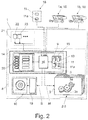
- Fig. 2 shows that the control system 8 preferably has a arranged on the harvester 1 driver assistance system 14, which controls the working members 2-5 of the harvester 1.
- the driver assistance system 14 includes in the illustrated and insofar preferred embodiment, a memory 15 for storing data - that is, a memory in the information technology sense - and a computing device 16 for processing the data stored in the memory 15.
- the driver assistance system 14 is set up to assist a driver 17 of the harvesting machine 1 in operating the harvesting machine 1.
- a remote assistance system 18 is provided, which communicates with the driver assistance system 14.
- the remote assistance system 18 may be a central planning system or the like, the driver assistance system 14 with prognosis inventory information. provided. Alternatively, it may be the remote assistance system 18 to the driver assistance system 14 of another harvester 1, 1a, 1b act.
- the setpoint travel speed S determined by the control system 8 may in principle be a setpoint speed directed to at least one future harvesting process section. This means that a forecast for the driving speed is made by the control system 8. This is particularly advantageous when Abtankzeitnos or the like. be predicted in order to synchronize the harvesting process with transport processes. This will also be explained below. Alternatively or additionally, it may be provided that the target travel speed S determined by the control system 8 is directed to the respective current harvesting process section. In both cases, the proposed solution, in particular the combination of forecasting inventory information 12 and actual stock information 13, ensures optimization of the setpoint driving speed S with regard to the implementation of the respective harvesting process strategy 9.
- the traction drive 10 of the harvester 1 is preferably associated with a vehicle speed control 19, wherein the vehicle speed control 19 sets the driving speed of the harvester 1 based on the respectively determined target vehicle speed S.
- a vehicle speed control 19 sets the driving speed of the harvester 1 based on the respectively determined target vehicle speed S.
- an input / output device 20 is provided, wherein the target vehicle speed S is displayed via the input / output device 20 for user-controlled tracking of the driving speed of the harvester 1.
- the input / output device 20 is a component of the above driver assistance system 14.
- the harvester 1 preferably has a sensor arrangement 21 for determining the actual yield information, which here and preferably comprises a grain tank sensor 22 for determining the fill level of the grain tank 7.
- the sensor assembly 21 may include other sensors such as For example, be associated with a population density sensor 23, as in the Fig. 1 and 2 is shown.
- the target driving speed S may be determined from the harvesting process strategy 9 and from the adapted forecasting inventory model 11a, which at least indirectly maps the actual stock information 13.
- the desired driving speed S is determined from the harvesting process strategy 9 and a here and preferably mathematical link between the actual stock information 13 and the forecast stock information 12.
- the mathematical combination is an averaging between the actual stock information 13 and the forecast stock information 12.
- the prediction inventory model 11 can be structured in different ways. It is preferable that the prediction inventory model 11 comprises reference-mark-predicted prognosis inventory information about the field to be harvested. This means that each prognosis stock information 12 is assigned a measuring mark 24. The measuring mark can be a position on the field to be harvested, a percentage of process progress within the harvesting process, or a point in time.
- Fig. 3a shows extracts from a georeferenced forecast inventory model 11. An exemplary measurement mark has been provided here with the reference numeral 24.
- a prognosis yield map P of the prognosis existing model 11 is shown on the right, wherein each measurement mark 24 in the prediction yield map P is assigned an output information, in particular an output set.
- measuring marks are distributed uniformly over the entire field, whose distances from one another correspond to the location resolution of the respective forecast.
- the measuring marks are distributed along predetermined measuring sections, which can be expected, for example, particularly high or very low yields.
- the forecast inventory model 11 may be composed of different data sources.
- the forecast inventory model 11 is generated, at least in part, from the actual stock information 13 of preceding or parallel harvesting processes.
- the prognosis inventory model 11 at least partially from aerial photographs, in particular satellite images and / or drone recordings is generated.
- the forecast inventory model 11 is at least partially generated from forecast weather information.
- the forecast inventory model 11 or the like at least partially via an input / output device 20. manually entered, field-related data is generated.
- the generation of the forecast inventory model 11 preferably takes place in a remote assistance system 18.
- the forecast inventory model 11 can also be obtained from third parties, in particular from a service provider.
- an above-mentioned adaptation of the prognosis inventory model 11 can be made.
- FIG. 3 Given that the inventory information is in each case yield information.
- yield information is shown along the lane of the harvester 1 around the area of a specific measuring mark 24.
- Fig. 3 shown on the right is the respective yield map, in which the measuring mark 24 is also entered.
- the amount of yield information which is here and preferably the area yield, is indicated in the respective yield map with the density of the points shown within the respective yield map.
- Fig. 3a shows the forecast inventory information 12 while Fig. 3b the actual inventory information up to a measurement mark 24 shows.
- the actual stock information 13 is compared with the respective forecast stock information 12.
- the prediction inventory information 12 is adapted to the actual inventory information 13.
- the thus-adapted forecast inventory model 11a is finally stored.
- the adaptation of the forecast inventory information 12 can be carried out exclusively at the respective measuring mark 24.
- Fig. 3a The representation according to Fig. 3a It can be seen that the prognosis inventory information 12 along the lane x of the harvester 1 have a certain course.
- the actual stock information 13 which is in Fig. 3b
- the proposed control system 8 ensures that the forecast yield information 12 as a whole and in particular for the future process sections to the actual yield information 13 be adapted.
- Fig. 3c illustrated, wherein the adjusted forecast inventory information 12a are indicated by the reference numeral 12a.
- the forecast yield map P is in Fig. 3a indicated by the reference P, while the actual yield map in Fig. 3b is indicated by the reference I.
- the adjusted forecast yield map is in Fig. 3c indicated by the reference numeral A.
- the above-mentioned adaptation of the prognosis inventory model 11 can be made at different locations.
- this adaptation is made in the driver assistance system 14 of the harvester 1.
- the adaptation can also be carried out in a remote assistance system 18 mentioned above.
- the proposed method allows a forward-looking determination of the target driving speed S of the harvester 1 based on a prognosis inventory model 11 with simultaneous inclusion of the actual stock information 13, which enables optimized control of the working organs 2-5 of the harvester 1.
- the proposed determination of the setpoint driving speed S within the framework of the planning of the harvesting process can be helpful if the setpoint driving speed S is also determined for future process sections.
- a preferred example is the implementation of a Abtankstrategie.
- an above Abtankstrategie comprises at least one sub-strategy, which is directed to the reduction of auxiliary times of the harvester 1 and / or on the reduction of transport paths of the respective transport device.
- a harvesting system with at least one self-propelled harvester 1, 1a, 1b, in particular a combine harvester is claimed for carrying out a method mentioned above.
- At least one harvester 1 of the proposed harvesting system is provided with a plurality of working members 2-5 discussed above and a control system 8 equipped to control the working organs 2-5. All statements relating to the proposed method according to the first-mentioned teaching, which are suitable for explaining the harvesting system and in particular the respective harvesting machine 1, may be referred to.
Landscapes
- Life Sciences & Earth Sciences (AREA)
- Environmental Sciences (AREA)
- Management, Administration, Business Operations System, And Electronic Commerce (AREA)
Abstract
Die Erfindung betrifft ein Verfahren zur Ansteuerung einer selbstfahrenden Erntemaschine (1) mit mehreren Arbeitsorganen (2-5) zum Verarbeiten des von einem abzuerntenden Feld (F) aufgenommenen Ernteguts im Rahmen eines Ernteprozesses, wobei die Arbeitsorgane (2-5) mittels eines Steuersystems (8) basierend auf einer Ernteprozessstrategie (9) angesteuert werden. Es wird vorgeschlagen, dass dem Steuersystem (8) ein zumindest zum Teil offline erzeugtes Prognose-Bestandsmodell (11) mit georeferenzierten Prognose-Bestandsinformationen (12) sowie online an der Erntemaschine (1) erzeugte, georeferenzierte Ist-Bestandsinformationen (13) bereitgestellt werden und dass eine Soll-Fahrgeschwindigkeit (S) für die Erntemaschine (1) mittels des Steuersystems (8) in Abhängigkeit von der Ernteprozessstrategie (9), von dem Prognose-Bestandsmodell (11) und von den Ist-Bestandsinformationen (13) ermittelt wird.The invention relates to a method for controlling a self-propelled harvesting machine (1) having a plurality of working members (2-5) for processing the crop picked up by a field (F) to be harvested during a harvesting process, wherein the working members (2-5) are controlled by means of a control system (2). 8) are driven based on a harvesting process strategy (9). It is proposed that the geo-referenced forecast inventory information (12) and georeferenced actual stock information (13) generated online on the harvesting machine (1) be provided to the control system (8), at least partially offline a target driving speed (S) for the harvesting machine (1) is determined by means of the control system (8) as a function of the harvesting process strategy (9), the forecasting inventory model (11) and the actual stock information (13).
Description
Die Erfindung betrifft ein Verfahren zur Ansteuerung einer selbstfahrenden Erntemaschine gemäß dem Oberbegriff von Anspruch 1 sowie ein Erntesystem mit mindestens einer selbstfahrenden Erntemaschine gemäß Anspruch 15.The invention relates to a method for controlling a self-propelled harvesting machine according to the preamble of
Selbstfahrenden Erntemaschinen wie Mähdreschern, Feldhäckslern o. dgl. sind eine Vielzahl von Maschinenparametern zugeordnet, die während des Ernteprozesses einzustellen sind. Die Maschinenparameter betreffen mehrere Arbeitsorgane der Arbeitsmaschine wie Schneidwerk, Dreschwerk, Abschneidevorrichtung o. dgl. der Erntemaschine.Self-propelled harvesters such as combine harvesters, forage harvesters or the like are associated with a plurality of machine parameters which are to be set during the harvesting process. The machine parameters relate to several working members of the working machine such as cutting unit, threshing unit, cutting device o. The like. The harvester.
Zwischenzeitlich sind eine Reihe von Lösungen zur automatisierten Ansteuerung einer selbstfahrenden Erntemaschine bekannt geworden. Dabei kommt der Ermittlung der Fahrgeschwindigkeit der Erntemaschine besondere Bedeutung zu. Die Fahrgeschwindigkeit bestimmt in Verbindung mit der Bestandsdichte den durch die Erntemaschine hindurchlaufenden Erntegutdurchsatz. Dadurch hängen eine Vielzahl von Maschinenparametern der Arbeitsorgane der selbstfahrenden Erntemaschine von der Fahrgeschwindigkeit ab.In the meantime, a number of solutions for the automated control of a self-propelled harvester have become known. In this case, the determination of the driving speed of the harvester is of particular importance. The driving speed, in conjunction with the crop density, determines the crop throughput passing through the harvester. As a result, a large number of machine parameters of the working elements of the self-propelled harvester depend on the driving speed.
Das bekannte Verfahren zur Ansteuerung einer selbstfahrenden Erntemaschine (
Die Nutzung prognostizierter Informationen für den Betrieb landwirtschaftlicher Verteilmaschinen wird in der
Die Nutzung von prognostizierten Informationen wie Wetterprognosen und Feuchtigkeitsprognosen für die Maschineneinsatzplanung und -einstellung ist der
Zwar bieten die bekannten Verfahren eine Reihe von Ansätzen für die zum Teil automatisierte Einstellung von Maschinenparametern. Dabei wird stellenweise auf prognostizierte Informationen zurückgegriffen, insbesondere um eine Planung des Ernteprozesses im Offline-Betrieb vornehmen zu können. Optimierungspotential ergibt sich hierbei im Hinblick auf die Ermittlung der Fahrgeschwindigkeit der Erntemaschine.Although the known methods provide a number of approaches for the sometimes automated setting of machine parameters. In some cases, forecast information is used, in particular in order to be able to plan the harvesting process in offline mode. Optimization potential arises here with regard to the determination of the driving speed of the harvester.
Der Erfindung liegt das Problem zugrunde, das bekannte Verfahren derart auszugestalten und weiterzubilden, dass die Ermittlung der Fahrgeschwindigkeit insbesondere bei sich über den Ernteprozess verändernden Bestandseigenschaften optimiert wird.The invention is based on the problem of designing and further developing the known method in such a way that the determination of the driving speed is optimized, particularly in the case of inventory properties which change over the harvesting process.
Das obige Problem wird bei einem Verfahren gemäß dem Oberbegriff von Anspruch 1 durch die Merkmale des kennzeichnenden Teils von Anspruch 1 gelöst.The above problem is solved in a method according to the preamble of
Die vorschlagsgemäße Lösung geht auf die Überlegung zurück, dass die Ermittlung einer Soll-Fahrgeschwindigkeit für die Erntemaschine auf einer Verknüpfung von Prognose-Bestandsinformationen mit Ist-Bestandsinformationen erfolgen kann. Damit ist einerseits eine Prognose der Soll-Fahrgeschwindigkeit und andererseits eine Orientierung der Soll-Fahrgeschwindigkeit auf die tatsächlichen Gegebenheiten möglich. Bei der Soll-Fahrgeschwindigkeit handelt es sich vorzugsweise um die Fahrgeschwindigkeit, die einer Fahrgeschwindigkeitssteuerung der Erntemaschine vorgegeben wird. Es kann aber auch eine manuelle Einstellung der Soll-Fahrgeschwindigkeit vorgesehen sein.The proposed solution is based on the consideration that the determination of a desired ground speed for the harvester can be made on a combination of forecast stock information with actual stock information. Thus, on the one hand, a prognosis of the nominal driving speed and, on the other hand, an orientation of the nominal driving speed to the actual conditions is possible. The target driving speed is preferably the driving speed that is predetermined for a driving speed control of the harvesting machine. But it can also be provided a manual adjustment of the desired driving speed.
Bei den Prognose-Bestandsinformationen handelt es sich um georeferenzierte Informationen zu dem in Rede stehenden Feld, die in einem Prognose-Bestandsmodell zusammengefasst sind. Das Prognose-Bestandsmodell ist zumindest zum Teil offline, also zeitlich versetzt zu dem jeweils laufenden Ernteprozess, erzeugt worden.The forecast inventory information is georeferenced information about the field in question, which is summarized in a forecast inventory model. The forecast inventory model has been generated at least partially offline, ie offset in time to the current harvesting process.
Bei den Ist-Bestandsinformationen handelt es sich um georeferenzierte Informationen zu dem in Rede stehenden Feld, die online an der Erntemaschine erzeugt werden.The actual stock information is georeferenced information about the field in question, which is generated online on the harvester.
Im Einzelnen wird nun vorgeschlagen, dass eine Soll-Fahrgeschwindigkeit für die Erntemaschine mittels des Steuersystems in Abhängigkeit von der Ernteprozessstrategie, von dem Prognose-Bestandsmodell und von den Ist-Bestandsinformationen ermittelt wird. Die Ernteprozessstrategie setzt sich aus einer Anzahl von Gütekriterien zusammen, die bei der Durchführung des Ernteprozesses relevant sind. Das Erfüllen der obigen Gütekriterien und damit das Einhalten der Ernteprozessstrategie setzt voraus, dass die Arbeitsorgane der Erntemaschine auf bestimmte Art und Weise angesteuert werden. Dabei können verschiedenen Gütekriterien unterschiedliche Prioritäten bei deren Berücksichtigung im Ernteprozess zukommen.Specifically, it is now proposed that a desired ground speed for the harvester be determined by means of the control system in dependence on the harvesting process strategy, the forecast inventory model and the actual stock information. The harvesting strategy strategy is composed of a number of quality criteria that are relevant in the execution of the harvesting process. Fulfilling the above quality criteria and thus adhering to the harvesting strategy assumes that the working organs of the harvesting machine are controlled in a certain way. Different quality criteria can have different priorities in their consideration in the harvesting process.
Die vorschlagsgemäße Lösung erlaubt nicht nur eine im Hinblick auf die jeweilige Ernteprozessstrategie optimale Ermittlung der Fahrgeschwindigkeit. Vielmehr ist mit der vorschlagsgemäßen Lösung eine Prognose der Fahrgeschwindigkeit möglich, dies angepasst auf die online an der Erntemaschine erzeugten Ist-Bestandsinformationen.The proposed solution not only allows an optimal determination of the driving speed with regard to the respective harvesting process strategy. Rather, with the proposed solution, a prognosis of the driving speed is possible, adapted to the actual stock information generated online at the harvesting machine.
Die Anpassung zumindest eines Teils des Prognose-Bestandsmodells basierend auf den Ist-Bestandsinformationen ist Gegenstand der Ansprüche 3 und 12. Dabei spielt jeweils die Variante eine besonders wichtige Rolle, bei der ein Teil des Prognose-Bestandsmodells angepasst wird, der mindestens einen zukünftigen Ernteprozessabschnitt betrifft. Dies bedeutet, dass sich das Prognose-Bestandsmodell online immer wieder auf die tatsächlichen Gegebenheiten anpassen lässt, so dass die Genauigkeit aller darauffolgenden Prognosen für die Fahrgeschwindigkeit ansteigt.The adaptation of at least part of the forecast inventory model based on the actual inventory information is the subject matter of
Eine vorteilhafte Aufteilung mehrerer Systeme bei der Erzeugung und Anpassung des Prognose-Bestandsmodells sowie der Ermittlung der Fahrgeschwindigkeit ergibt sich gemäß Anspruch 5 dadurch, dass ein an der Erntemaschine angeordnetes Fahrerassistenzsystem vorgesehen ist, das mit mindestens einem separat von der Erntemaschine angeordneten Fernassistenzsystem kommuniziert. Bei dem Fernassistenzsystem kann es sich um ein zentrales Planungssystem oder aber um das Fahrerassistenzsystem einer weiteren Erntemaschine handeln. Auf diese Weise lässt sich ein Erntesystem aus mehreren Erntemaschinen und ggf. einem zentralen Planungssystem erzeugen, bei dem relevante Informationen, insbesondere Prognose-Bestandsinformationen, ausgetauscht werden können.An advantageous division of several systems in the production and adaptation of the prognosis inventory model and the determination of the driving speed results according to
Die Soll-Fahrgeschwindigkeit kann, wie oben angegeben, einer Fahrgeschwindigkeitssteuerung zur Ansteuerung des Fahrantriebs vorgegeben werden (Anspruch 7). Alternativ kann es aber auch vorgesehen sein, dass die Umsetzung der Soll-Fahrgeschwindigkeit manuell, also durch den Benutzer, vorgenommen wird. Hierfür ist eine Ein-/Ausgabevorrichtung vorgesehen, über welche die ermittelte Soll-Fahrgeschwindigkeit zur Einstellung durch den Benutzer angezeigt wird.The target vehicle speed can, as indicated above, a vehicle speed control for driving the drive to be specified (claim 7). Alternatively, however, it can also be provided that the conversion of the desired driving speed is carried out manually, that is to say by the user. For this purpose, an input / output device is provided, via which the determined target driving speed is displayed for adjustment by the user.
Für die Erzeugung des Prognose-Bestandsmodells sind verschiedene bevorzugte Varianten denkbar (Anspruch 11). In besonders bevorzugter Ausgestaltung wird das Prognose-Bestandsmodell zumindest zum Teil aus den Ist-Bestandsinformationen vorangegangener oder parallel ablaufender Ernteprozesse erzeugt. Dadurch kann auf aufwendige technische Hilfsmittel zur Erzeugung des Prognose-Bestandsmodells verzichtet werden.For the generation of the prognosis model, various preferred variants are conceivable (claim 11). In a particularly preferred embodiment, the forecast inventory model is generated, at least in part, from the actual stock information of preceding or parallel harvesting processes. As a result, it is possible to dispense with expensive technical aids for generating the prognosis inventory model.
Die vorschlagsgemäße Lösung lässt sich für die Prognose von Abtankzeitpunkten vorteilhaft einsetzen (Anspruch 14). Dabei wird mindestens ein Abtankzeitpunkt nach einer vorbestimmten Abtankstrategie in Abhängigkeit von der Ernteprozessstrategie, von dem Prognose-Bestandsmodell und von den Ist-Bestandsinformationen ermittelt. Interessant dabei ist die Tatsache, dass bei der oben angesprochenen Anpassung des Prognose-Bestandsmodells eine Prognose von Abtankzeitpunkten besonders präzise möglich ist.The proposed solution can be used advantageously for the prognosis of Abtankzeitpunkten (claim 14). In this case, at least one Abtankzeitpunkt is determined according to a predetermined Abtankstrategie depending on the harvesting process strategy, the forecast inventory model and the actual inventory information. Interesting is the fact that in the above-mentioned adaptation of the forecasting inventory model, a forecast of Abtankzeitpunkten is particularly precise possible.
Nach einer weiteren Lehre gemäß Anspruch 15, der eigenständige Bedeutung zukommt, wird ein Erntesystem mit mindestens einer selbstfahrenden Erntemaschine, hier und vorzugsweise mit mehreren selbstfahrenden Erntemaschinen, beansprucht, das zur Durchführung eines vorschlagsgemäßen Verfahrens ausgelegt ist. Im Einzelnen ist zumindest eine Erntemaschine des Erntesystems dafür ausgelegt, durch das vorschlagsgemäße Verfahren angesteuert zu werden.According to another teaching according to
Weitere Einzelheiten, Merkmale, Ziele und Vorteile der vorliegenden Erfindung werden nachfolgend anhand der Zeichnung eines bevorzugten Ausführungsbeispiels näher erläutert. In der Zeichnung zeigt
- Fig. 1
- eine Seitenansicht einer Erntemaschine eines vorschlagsgemäßen Erntesystems zur Durchführung eines vorschlagsgemäßen Verfahrens,
- Fig. 2
- eine schematische Darstellung des Steuersystems der Erntemaschine gemäß
Fig. 1 und - Fig. 3
- den Verlauf einer Bestandsinformation entlang der Fahrspur der Erntemaschine gemäß
Fig. 1 a) als Prognose-Information, b) als Ist-Information bis zu einer Messmarke und c) als an die Ist-Information angepasste Prognose-Information.
- Fig. 1
- a side view of a harvesting machine of a proposed harvesting system for carrying out a proposed method,
- Fig. 2
- a schematic representation of the control system of the harvester according to
Fig. 1 and - Fig. 3
- the course of a stock information along the lane of the harvester according to
Fig. 1 a) as forecast information, b) as actual information up to a measurement mark, and c) as prognosis information adapted to the actual information.
Ein vorschlagsgemäßes Erntesystem mit mindestens einer selbstfahrenden Erntemaschine 1 kann auf unterschiedliche Anwendungsfälle ausgelegt sein. Nachfolgend steht die selbstfahrende Erntemaschine "Mähdrescher" im Vordergrund. Alle Ausführungen zu einem Mähdrescher gelten für alle anderen Arten von selbstfahrenden Erntemaschinen, insbesondere für einen Feldhäcksler, entsprechend. Das Erntesystem kann grundsätzliche mehrere Erntemaschinen 1, 1a, 1 b umfassen.A proposed harvesting system with at least one self-propelled
Eine obige Erntemaschine 1 weist mehrere Arbeitsorgane 2-5 zum Verarbeiten des von einem abzuerntenden Feld aufgenommenen Ernteguts im Rahmen eines Ernteprozesses auf.An above
Bei einem Mähdrescher handelt es sich bei dem Arbeitsorgan 2 um ein Schneidwerk, das dem Schneiden des Ernteguts und der Zuführung des geschnittenen Ernteguts zu dem nächsten, als Dreschwerk ausgestalteten Arbeitsorgan 3 dient. Das Dreschwerk 3 dient dem Dreschen von aufgenommenem Erntegut zu Korngut. Unter dem Erntegut ist hier das gesamte vom Feldbestand aufgenommene und dem Dreschwerk 3 zugeführte Material zu verstehen, wobei das Korngut dann die von dem Mähdrescher aus dem Erntegut zu gewinnenden Körner bezeichnet.In a combine harvester, the working
Das Dreschwerk 3 ist hier und vorzugsweise mit einer Dreschtrommel 3a ausgestattet, die mit einem Dreschkorb 3b zusammenwirkt. Dem Dreschwerk 3 ist ein als Abscheideanordnung ausgestaltetes Arbeitsorgan 4 nachgelagert. Der dem Dreschwerk 3 zugeführte Erntegutstrom wird also im Anschluss - ohne das bereits hier gewonnene Korngut - der Abscheideanordnung 4 zugeführt.The threshing
Grundsätzlich dient das Dreschwerk 3 zum Ausreiben des überwiegenden Teils des Kornguts aus dem Stroh des Ernteguts durch den Dreschvorgang. In dem als Abscheideanordnung ausgestalteten Arbeitsorgan 4 wird dann das Erntegut mit dem in ihm verbliebenen Kornanteil so bewegt, z. B. geschüttelt, dass auch das verbliebene Korngut möglichst aus dem Stroh und dem sonstigen Erntegut herausgetrennt wird. Das im Dreschwerk 3 und der Abscheideanordnung 4 gewonnene Korngut wird dann dem als Reinigungsanordnung ausgestalteten Arbeitsorgan 5 zugeführt. In der Reinigungsanordnung 5, welche regelmäßig mehrstufig ist, werden dann noch bis hierher im Korngut mitgeführte Nichtkornbestandteile, z. B. Spreu und Strohteile, sowie unausgedroschenes Material, wie etwa Ähren, Spitzen oder Grannen, von dem Korngut getrennt. Anschließend gelangt das gereinigte Korngut über eine Transportanordnung 6, z. B. einen Kornelevator, in einen Korntank 7. Das ausgedroschene Stroh - also das verbliebene Erntegut in der Abscheideanordnung 4 - wird von dem Mähdrescher abgelegt, z. B. als Schwad entlang der Fahrspur.Basically, the threshing
Die obigen Arbeitsorgane 2-5 können jeweils durch die Vorgabe verschiedener Maschinenparameter angesteuert werden. Ein obiges Dreschwerk 3 kann beispielsweise durch die Vorgabe verschiedener Dreschwerksparameter angesteuert werden. Hierunter fallen in Abhängigkeit vom Aufbau des Dreschwerks 3 Antriebsparameter wie beispielsweise eine Trommeldrehzahl oder sonstige Bewegungskennzahlen der Dreschtrommel 3a, sowie eine Korbweite - also der Abstand zwischen der Dreschtrommel 3a und einem Dreschkorb 3b. Der optimalen Ansteuerung der Arbeitsorgane 2-5 kommt für die erzielbare Erntequalität und den erzielbaren Erntegutdurchsatz besondere Bedeutung zu. Hierfür ist es vorschlagsgemäß vorgesehen, dass die Arbeitsorgane 2-5 der Erntemaschine 1 mittels eines Steuersystems 8 basierend auf einer Ernteprozessstrategie 9 angesteuert werden. Die Ernteprozessstrategie umfasst dabei eine Zielvorgabe der Einstellung oder der Optimierung von Ernteprozessparametern. Die Umsetzung der Ernteprozessstrategie soll dabei jeweils durch eine entsprechende Vorgabe von Maschinenparametern der Arbeitsorgane 2-5 durch das Steuersystem 8 erfolgen. In Abhängigkeit von der Ausgestaltung des Steuersystems 8 kann es möglich sein, die jeweilige Ernteprozessstrategie aus einer Anzahl vorbestimmter Ernteprozessstrategien auszuwählen und/oder eine Parametrierung der jeweiligen Ernteprozessstrategie benutzerdefiniert vorzunehmen.The above working organs 2-5 can each be controlled by specifying various machine parameters. An above threshing
Die vorschlagsgemäße, selbstfahrende Erntemaschine 1 ist mit einem Fahrantrieb 10 ausgestattet, der vorliegend nicht als Arbeitsorgan im obigen Sinne zu verstehen ist. Dies liegt daran, dass der Fahrantrieb 10 nicht dem Verarbeiten des von einem abzuerntenden Feld aufgenommenen Ernteguts dient. Gleichwohl kommt der Ansteuerung des Fahrantriebs 10 mit der resultierenden Fahrgeschwindigkeit für das Prozessergebnis ganz besondere Bedeutung zu. Der Fahrantrieb 10 wird durch das Steuersystem 8 angesteuert.The proposed, self-propelled
Für die Einstellung der Fahrgeschwindigkeit werden dem Steuersystem 8 vorschlagsgemäß verschiedene Informationen bereitgestellt. Hierzu gehört zunächst ein zumindest zum Teil offline erzeugtes Prognose-Bestandsmodell 11 mit georeferenzierten Prognose-Bestandsinformationen. Dies bedeutet, dass das Prognose-Bestandsmodell 11 zeitlich vor dem Ablauf des Ernteprozesses erzeugt worden ist, beispielsweise basierend auf vorangegangenen Ernteprozessen o.dgl. Dies wird weiter unten erläutert. Die Bestandsinformationen können alle Arten von Informationen zur Beschreibung des Bestandes umfassen. Dies wird ebenfalls weiter unten erläutert.For setting the vehicle speed, the
Zusätzlich zu dem obigen, offline erzeugten Prognose-Bestandsmodell 11 werden dem Steuersystem 8 auch online an der Erntemaschine 1 erzeugte, georeferenzierte Ist-Bestandsinformationen 13 bereitgestellt. Die Ist-Bestandsinformationen 13 werden also im Laufe des Ernteprozesses erzeugt.In addition to the above-generated
Vorschlagsgemäß ist es nun so, dass eine Soll-Fahrgeschwindigkeit S für die Erntemaschine 1 mittels des Steuersystems 8 in Abhängigkeit von der jeweiligen Ernteprozessstrategie 9, von dem Prognose-Bestandsmodell 11 und von den Ist-Bestandsinformationen 13 ermittelt wird. Damit nutzt das Steuersystem 8 zur Ermittlung der Soll-Fahrgeschwindigkeit S zunächst das zumindest zum Teil offline erzeugte Prognose-Bestandsmodell 11, das zwar eine vorausschauende Ansteuerung erlaubt, das jedoch aufgrund des Zeitversatzes zwischen der Erzeugung des Prognose-Bestandsmodells 11 und der Durchführung des Ernteprozesses sowie ggf. auch Messsystem-bedingt einen Mangel an Genauigkeit aufweist. Zum Ausgleich dieses Mangels an Genauigkeit stehen dem Steuersystem 8 die Ist-Bestandsinformationen 13 zur Verfügung, die die tatsächlich vorliegenden Gegebenheiten während des Ernteprozesses widerspiegeln.According to the proposal, it is now so that a target vehicle speed S for the
Wie oben angedeutet, können die jeweiligen Bestandsinformationen 12, 13 auf unterschiedliche Aspekte des Bestandes gerichtet sein. Dazu gehören neben Ertragsinformationen auch die Bestandsdichte, die Bestandshöhe, die Bestandszusammensetzung, der Bestandsreifegrad, die Lagerfruchtinformation, der Fremdpflanzenanteil, der Grüngutanteil, der Bestandsuntergrund o.dgl. Hier und vorzugsweise ist es vorgesehen, dass die Bestandsinformationen 12, 13 jeweils Ertragsinformationen zum Bestand umfassen. Im Falle einer als Mähdrescher ausgestalteter Erntemaschine 1 kann es sich hierbei um Informationen über den zu erwartenden Flächenertrag handeln.As indicated above, the
Die Prognose-Bestandinformationen 12 können in dem jeweils aktuellen Prozesszeitpunkt miteinander verknüpft und dem Steuersystem 8 zugeführt werden, wie weiter unten erläutert wird. Alternativ oder zusätzlich kann es jedoch vorgesehen sein, dass zumindest ein Teil des Prognose-Bestandmodells 11 basierend auf den Ist-Bestandsinformationen 13 angepasst und das angepasste Prognose-Bestandsmodell 11a gespeichert wird. Die Anpassung erfolgt vorzugsweise derart, dass sich die Prognose-Bestandsinformationen 12 an die dazugehörigen Ist-Bestandsinformationen 13 annähern.The
Für alle weiteren Ermittlungen, insbesondere die Ermittlung der Soll-Fahrgeschwindigkeit S, wird nunmehr das angepasste Prognose-Bestandsmodell 11a herangezogen, das wiederum einer entsprechenden Anpassung unterzogen sein kann. Vorzugsweise wird das Prognose-Bestandsmodell 11 mit dem angepassten Prognose-Bestandsmodell 11a überschrieben. Lediglich zur besseren Übersichtlichkeit sind das Prognose-Bestandsmodell 11 und das angepasste Prognose-Bestandsmodell 11a in den Zeichnungen als separat gespeicherte Einheiten dargestellt.For all further determinations, in particular the determination of the setpoint driving speed S, the adjusted
Eine interessante Erkenntnis besteht darin, dass sich eine Reihe von Einflussfaktoren für den Bestand nicht nur lokal, insbesondere nicht nur auf eine gesonderte Position im Feld, auswirken. Dies bedeutet, dass eine im Prozess erfasste Abweichung zwischen den Ist-Bestandsinformationen 13 und den Prognose-Bestandsinformationen 12 genutzt werden kann, um die Prognose-Bestandinformationen 12 für das gesamte Feld an die tatsächlichen Gegebenheiten anzupassen. Ein Beispiel hierfür ist eine Abweichung der Ist-Bestandsinformationen 13 von den Prognose-Bestandsinformationen 12 durch einen an sich erwarteten Regen-Niederschlag, der sich aber nicht realisiert hat. Bei der Erfassung einer obigen Abweichung kann in einem solchen Fall darauf geschlossen werden, dass die gesamten Prognose-Bestandsinformationen 12, beispielsweise die Prognose-Ertragsinformationen, in ähnlicher Weise anzupassen sind. Auch dies wird weiter unten noch im Detail erläutert. Ganz allgemein ist es so, dass ein mindestens einen zukünftigen Ernteprozessabschnitt betreffender Teil des Prognose-Bestandsmodells 11 basierend auf den Ist-Bestandsinformationen 12 angepasst und gespeichert wird.An interesting finding is that a number of factors affecting stock are not only local, and not just a separate item in the field. This means that one captured in the process Deviation between the
Hier und vorzugsweise umfasst die Ernteprozessstrategie 9 eine Teilstrategie, die auf einen vorbestimmten und/oder maximalen und/oder über den Ernteprozess gleichmäßigen Erntegutdurchsatz gerichtet ist. Alternativ oder zusätzlich kann die Ernteprozessstrategie 9 eine Teilstrategie umfassen, die auf einen vorbestimmten und/oder maximalen und/oder über den Ernteprozess gleichmäßigen Ertrag pro Zeiteinheit gerichtet ist. Andere Ausprägungen der Ernteprozessstrategie sind denkbar.Here and preferably, the harvesting process strategy 9 comprises a sub-strategy which is directed to a predetermined and / or maximum and / or crop throughput which is uniform over the harvesting process. Alternatively or additionally, the harvesting process strategy 9 may include a sub-strategy directed to a predetermined and / or maximum and / or uniform yield per unit time over the harvesting process. Other characteristics of the harvesting process strategy are conceivable.
In besonders bevorzugter Ausgestaltung ist zusätzlich zu dem Fahrerassistenzsystem 14 ein Fernassistenzsystem 18 vorgesehen, das mit dem Fahrerassistenzsystem 14 kommuniziert. Dabei kann das Fernassistenzsystem 18 ein zentrales Planungssystem sein, das das Fahrerassistenzsystem 14 mit Prognose-Bestandsinformationen o.dgl. versorgt. Alternativ dazu kann es sich bei dem Fernassistenzsystem 18 um das Fahrerassistenzsystem 14 einer weiteren Erntemaschine 1, 1a, 1b handeln.In a particularly preferred embodiment, in addition to the
Bei der durch das Steuersystem 8 ermittelten Soll-Fahrgeschwindigkeit S kann es sich grundsätzlich um eine auf mindestens einen zukünftigen Ernteprozessabschnitt gerichtete Soll-Geschwindigkeit handeln. Dies bedeutet, dass durch das Steuersystem 8 eine Prognose für die Fahrgeschwindigkeit vorgenommen wird. Dies ist insbesondere vorteilhaft, wenn Abtankzeitpunkte o.dgl. prognostiziert werden sollen, um eine Synchronisierung des Ernteprozesses mit Transportprozessen zu erreichen. Auch dies wird weiter unten erläutert. Alternativ oder zusätzlich kann es vorgesehen sein, dass die durch das Steuersystem 8 ermittelte Soll-Fahrgeschwindigkeit S auf den jeweils aktuellen Ernteprozessabschnitt gerichtet ist. In beiden Fällen sorgt die vorschlagsgemäße Lösung, insbesondere die Verknüpfung von Prognose-Bestandsinformationen 12 und Ist-Bestandsinformationen 13, für eine Optimierung der Soll-Fahrgeschwindigkeit S im Hinblick auf die Umsetzung der jeweiligen Ernteprozessstrategie 9.The setpoint travel speed S determined by the
Dem Fahrantrieb 10 der Erntemaschine 1 ist vorzugsweise eine Fahrgeschwindigkeitssteuerung 19 zugeordnet, wobei die Fahrgeschwindigkeitssteuerung 19 die Fahrgeschwindigkeit der Erntemaschine 1 basierend auf der jeweils ermittelten Soll-Fahrgeschwindigkeit S einstellt. Damit ist eine weitgehend automatisierte Einstellung der Fahrgeschwindigkeit der Erntemaschine 1 möglich. Alternativ oder zusätzlich kann es vorgesehen sein, dass eine Ein-/Ausgabevorrichtung 20 vorgesehen ist, wobei die Soll-Fahrgeschwindigkeit S über die Ein-/ Ausgabevorrichtung 20 zum benutzergeführten Nachführen der Fahrgeschwindigkeit der Erntemaschine 1 angezeigt wird. Hier und vorzugsweise handelt es sich bei der Ein-/ Ausgabevorrichtung 20 um einen Bestandteil des obigen Fahrerassistenzsystems 14.The traction drive 10 of the
Auch für die Ermittlung der Ist-Bestandsinformationen 13 sind in Abhängigkeit von den zu ermittelnden Informationen zahlreiche vorteilhafte Varianten denkbar. Für den Fall, dass es sich bei den zu ermittelnden Bestandsinformationen um Ertragsinformationen handelt, weist die Erntemaschine 1 zur Ermittlung der Ist-Ertragsinformationen vorzugsweise eine Sensoranordnung 21 auf, die hier und vorzugsweise einen Korntanksensor 22 zur Ermittlung des Füllstandes des Korntanks 7 umfasst. Der Sensoranordnung 21 können weitere Sensoren wie beispielsweise ein Bestandsdichtesensor 23 zugeordnet sein, wie in den
Grundsätzlich kann es vorgesehen sein, dass die Soll-Fahrgeschwindigkeit S aus der Ernteprozessstrategie 9 und aus dem angepassten Prognose-Bestandsmodell 11a, das ja zumindest mittelbar die Ist-Bestandsinformationen 13 abbildet, ermittelt wird. Hier und vorzugsweise ist es allerdings so, dass die Soll-Fahrgeschwindigkeit S aus der Ernteprozessstrategie 9 und einer hier und vorzugsweise mathematischen Verknüpfung zwischen den Ist-Bestandsinformationen 13 und den Prognose-Bestandsinformationen 12 ermittelt wird. Im einfachsten Fall handelt es sich bei der mathematischen Verknüpfung um eine Mittelwertbildung zwischen den Ist-Bestandsinformationen 13 und den Prognose-Bestandsinformationen 12.In principle, provision may be made for the target driving speed S to be determined from the harvesting process strategy 9 and from the adapted
Das Prognose-Bestandsmodell 11 kann auf unterschiedliche Weise strukturiert se. Vorzugsweise ist es so, dass das Prognose-Bestandsmodell 11 messmarkenreferenzierte Prognose-Bestandsinformationen zu dem abzuerntenden Feld umfasst. Dies bedeutet, dass jeder Prognose-Bestandsinformation 12 eine Messmarke 24 zugeordnet ist. Die Messmarke kann eine Lage auf dem abzuerntenden Feld, ein prozentualer Prozessfortschritt innerhalb des Ernteprozesses oder ein Zeitpunkt sein.
Das Prognose-Bestandsmodell 11 kann aus verschiedenen Datenquellen zusammengesetzt sein. Eine Möglichkeit besteht darin, dass das Prognose-Bestandsmodell 11 zumindest zum Teil aus den Ist-Bestandsinformationen 13 vorangegangener oder parallel ablaufender Ernteprozesse erzeugt wird. Alternativ oder zusätzlich kann es vorgesehen sein, dass das Prognose-Bestandsmodell 11 zumindest zum Teil aus Luftaufnahmen, insbesondere aus Satellitenaufnahmen und/oder Drohnenaufnahmen erzeugt wird. Wiederum alternativ oder zusätzlich kann es vorgesehen sein, dass das Prognose-Bestandsmodell 11 zumindest zum Teil aus Prognose-Wetterinformationen erzeugt wird. Schließlich kann es alternativ oder zusätzlich vorgesehen sein, dass das Prognose-Bestandsmodell 11 zumindest zum Teil aus über eine Ein-/ Ausgabevorrichtung 20 o.dgl. manuell eingegebene, feldbezogene Daten erzeugt wird.The
Die Erzeugung des Prognose-Bestandsmodells 11 erfolgt vorzugsweise in einem Fernassistenzsystem 18. Grundsätzlich kann das Prognose-Bestandsmodell 11 auch von dritter Seite, insbesondere von einem Dienstleister, bezogen werden. Dann ist es vorzugsweise so, dass das Prognose-Bestandsmodell 11 von dem jeweiligen Dienstleister an das Fernassistenzsystem 18 und von dem Fernassistenzsystem 18 an das Fahrerassistenzsystem 14 übermittelt wird. Sowohl im Fernassistenzsystem 18, als auch im Fahrerassistenzsystem 14 kann eine oben angesprochene Anpassung des Prognose-Bestandsmodells 11 vorgenommen werden.The generation of the
Eine beispielhafte Vorgehensweise zur Anpassung des Prognose-Bestandsmodells 11 an die Ist-Bestandsinformationen 13 wird nun mit Bezug auf die Darstellungen gemäß
Vorzugsweise werden mittels des Steuersystems 8 an mindestens einer Messmarke 24 im laufenden Ernteprozess die Ist-Bestandsinformationen 13 mit den jeweiligen Prognose-Bestandsinformationen 12 verglichen. Dies entspricht einem Vergleich der in
Der Darstellung gemäß
Die oben angesprochene Anpassung des Prognose-Bestandmodells 11 kann an unterschiedlichen Stellen vorgenommen werden. Hier und vorzugsweise wird diese Anpassung in dem Fahrerassistenzsystem 14 der Erntemaschine 1 vorgenommen. Alternativ oder zusätzlich kann die Anpassung aber auch in einem oben angesprochenen Fernassistenzsystem 18 vorgenommen werden.The above-mentioned adaptation of the
Weiter kann es vorgesehen sein, dass die Ist-Bestandsinformationen 13 und/oder das angepasste Prognose-Bestandsmodell 11a an mindestens ein Fernassistenzsystem 18, hier und vorzugsweise an das Fahrerassistenzsystem 14 mindestens einer weiteren Erntemaschine 1a, 1 b, übermittelt wird. Denkbar ist aber auch, dass das angepasste Prognose-Bestandsmodell 11a ausschließlich in dem Fahrerassistenzsystem 18 der Erntemaschine 1 gespeichert ist.Furthermore, provision may be made for the
Das vorschlagsgemäße Verfahren ermöglicht eine vorausschauende Ermittlung der Soll-Fahrgeschwindigkeit S der Erntemaschine 1 basierend auf einem Prognose-Bestandsmodell 11 unter gleichzeitiger Einbeziehung der Ist-Bestandsinformationen 13, was eine optimierte Ansteuerung der Arbeitsorgane 2-5 der Erntemaschine 1 ermöglicht. Zusätzlich kann die vorschlagsgemäße Ermittlung der Soll-Fahrgeschwindigkeit S im Rahmen der Planung des Ernteprozesses hilfreich sein, wenn die Soll-Fahrgeschwindigkeit S auch für zukünftige Prozessabschnitte ermittelt wird. Ein bevorzugtes Beispiel ist die Umsetzung einer Abtankstrategie. Dabei wird davon ausgegangen, dass die Erntemaschine 1 einem Ernteguttank, insbesondere einen oben angesprochenen Korntank 7, aufweist, wobei nach einer vorbestimmten Abtankstrategie in Abhängigkeit von der Ernteprozessstrategie 9, von dem Prognose-Bestandsmodell 11 und von den Ist-Bestandsinformationen 13 mindestens ein Abtankzeitpunkt ermittelt wird, in dem die Erntemaschine 1 das Erntegut auf eine nicht dargestellte Transporteinrichtung umlädt. In besonders bevorzugter Ausgestaltung umfasst eine obige Abtankstrategie mindestens eine Teilstrategie, die auf die Reduzierung von Hilfszeiten der Erntemaschine 1 und/oder auf die Reduzierung von Transportwegen der jeweiligen Transporteinrichtung gerichtet ist. Dadurch, dass mit der vorschlagsgemäßen Lösung eine Prognose der Fahrgeschwindigkeit der Erntemaschine 1 möglich ist, ergibt sich auch die Möglichkeit der Prognose von Abtankzeitpunkten im Rahmen der oben angesprochenen Planung.The proposed method allows a forward-looking determination of the target driving speed S of the
Nach einer weiteren Lehre, der eigenständige Bedeutung zukommt, wird ein Erntesystem mit mindestens einer selbstfahrenden Erntemaschine 1, 1a, 1b, insbesondere einem Mähdrescher, zur Durchführung eines oben angesprochenen Verfahrens beansprucht.According to another teaching, which has independent significance, a harvesting system with at least one self-propelled
Mindestens eine Erntemaschine 1 des vorschlagsgemäßen Erntesystems ist mit mehreren, oben angesprochenen Arbeitsorganen 2-5 und mit einem Steuersystem 8 zur Ansteuerung der Arbeitsorgane 2-5 ausgestattet. Auf alle Ausführungen zu dem vorschlagsgemäßen Verfahren gemäß der erstgenannten Lehre, die geeignet sind, das Erntesystem und insbesondere die jeweilige Erntemaschine 1 zu erläutern, darf verwiesen werden.At least one
- 11
- Erntemaschineharvester
- 22
- Schneidwerkcutting
- 33
- Dreschwerkthreshing
- 3a3a
- Dreschtrommelthreshing
- 3b3b
- Dreschkorbconcave
- 44
- AbscheideanordnungAbscheideanordnung
- 55
- Reinigungsanordnungcleaning arrangement
- 66
- Transportanordnungtransport arrangement
- 77
- Korntankgrain tank
- 88th
- Steuersystemcontrol system
- 99
- ErnteprozessstrategieHarvesting process strategy
- 1010
- Fahrantriebtraction drive
- 1111
- Prognose-BestandsmodellForecasting inventory model
- 11a11a
- angepasstes Prognose-Bestandsmodelladapted forecasting inventory model
- 1212
- Prognose-BestandsinformationForecasting inventory information
- 12a12a
- angepasste Prognose-Bestandsinformationcustomized forecasting stock information
- 1313
- Ist-BestandsinformationActual inventory information
- 1414
- FahrerassistenzsystemDriver assistance system
- 1515
- SpeicherStorage
- 1616
- Rechenvorrichtungcomputing device
- 1717
- Fahrerdriver
- 1818
- FernassistenzsystemRemote assistance system
- 1919
- FahrgeschwindigkeitssteuerungCruise control
- 2020
- Ein-/AusgabevorrichtungInput / output device
- 2121
- Sensoranordnungsensor arrangement
- 2222
- KorntanksensorGrain tank sensor
- 2323
- BestandsdichtesensorPopulation density sensor
- 2424
- Messmarkemeasuring mark
- AA
- Angepasste Prognose-ErtragskarteAdapted forecast yield map
- FF
- Feldfield
- II
- Ist-ErtragskarteActual yield map
- MM
- Maschinenparametermachine parameters
- PP
- Prognose-ErtragskarteForecasting yield map
- SS
- Soll-FahrgeschwindigkeitTarget vehicle speed
- xx
- Fahrspurlane
Claims (15)
dadurch gekennzeichnet,
dass dem Steuersystem (8) ein zumindest zum Teil offline erzeugtes Prognose-Bestandsmodell (11) mit georeferenzierten Prognose-Bestandsinformationen (12) sowie online an der Erntemaschine (1) erzeugte, georeferenzierte Ist-Bestandsinformationen (13) bereitgestellt werden und dass eine Soll-Fahrgeschwindigkeit (S) für die Erntemaschine (1) mittels des Steuersystems (8) in Abhängigkeit von der Ernteprozessstrategie (9), von dem Prognose-Bestandsmodell (11) und von den Ist-Bestandsinformationen (13) ermittelt wird.Method for controlling a self-propelled harvesting machine (1) having a plurality of working members (2-5) for processing the crop picked up by a field (F) to be harvested as part of a harvesting process, wherein the working members (2-5) are controlled by a control system (8) a harvest process strategy (9) are controlled
characterized,
in that the control system (8) provides a forecast inventory model (11) with geo-referenced forecast inventory information (12) generated at least partially offline, as well as georeferenced actual stock information (13) generated online on the harvesting machine (1) and that a target Driving speed (S) for the harvester (1) by means of the control system (8) in dependence on the harvesting process strategy (9), the forecast inventory model (11) and the actual stock information (13) is determined.
Applications Claiming Priority (1)
| Application Number | Priority Date | Filing Date | Title |
|---|---|---|---|
| DE102015108374.4A DE102015108374A1 (en) | 2015-05-27 | 2015-05-27 | Method for controlling a self-propelled harvesting machine |
Publications (1)
| Publication Number | Publication Date |
|---|---|
| EP3097759A1 true EP3097759A1 (en) | 2016-11-30 |
Family
ID=55443182
Family Applications (1)
| Application Number | Title | Priority Date | Filing Date |
|---|---|---|---|
| EP16157834.9A Withdrawn EP3097759A1 (en) | 2015-05-27 | 2016-02-29 | Method for controlling a self-propelled harvesting machine |
Country Status (2)
| Country | Link |
|---|---|
| EP (1) | EP3097759A1 (en) |
| DE (1) | DE102015108374A1 (en) |
Cited By (41)
| Publication number | Priority date | Publication date | Assignee | Title |
|---|---|---|---|---|
| EP3578032A1 (en) * | 2018-06-05 | 2019-12-11 | CLAAS Selbstfahrende Erntemaschinen GmbH | Method for controlling an agricultural harvesting programme |
| CN112219538A (en) * | 2019-07-15 | 2021-01-15 | 克拉斯自行式收获机械有限公司 | Method for carrying out an agricultural harvesting process |
| EP3818803A1 (en) * | 2019-11-09 | 2021-05-12 | 365FarmNet Group KGaA mbh & Co KG | Assistance system for determining a profit prognosis of an agricultural field |
| US11079725B2 (en) | 2019-04-10 | 2021-08-03 | Deere & Company | Machine control using real-time model |
| US11178818B2 (en) | 2018-10-26 | 2021-11-23 | Deere & Company | Harvesting machine control system with fill level processing based on yield data |
| US11234366B2 (en) | 2019-04-10 | 2022-02-01 | Deere & Company | Image selection for machine control |
| US11240961B2 (en) | 2018-10-26 | 2022-02-08 | Deere & Company | Controlling a harvesting machine based on a geo-spatial representation indicating where the harvesting machine is likely to reach capacity |
| EP3626038B1 (en) | 2018-09-24 | 2022-03-09 | CLAAS Tractor S.A.S. | Agricultural machine |
| EP3981231A1 (en) * | 2020-10-08 | 2022-04-13 | Deere & Company | Predictive machine characteristic map generation and control system |
| EP3981234A1 (en) * | 2020-10-08 | 2022-04-13 | Deere & Company | Predictive map generation and control system |
| EP3981235A1 (en) * | 2020-10-08 | 2022-04-13 | Deere & Company | Predictive map generation and control system |
| EP3981233A1 (en) * | 2020-10-08 | 2022-04-13 | Deere & Company | Map generation and control system |
| US20220110251A1 (en) | 2020-10-09 | 2022-04-14 | Deere & Company | Crop moisture map generation and control system |
| US11467605B2 (en) | 2019-04-10 | 2022-10-11 | Deere & Company | Zonal machine control |
| US11474523B2 (en) | 2020-10-09 | 2022-10-18 | Deere & Company | Machine control using a predictive speed map |
| US11477940B2 (en) | 2020-03-26 | 2022-10-25 | Deere & Company | Mobile work machine control based on zone parameter modification |
| US11592822B2 (en) | 2020-10-09 | 2023-02-28 | Deere & Company | Machine control using a predictive map |
| US11589509B2 (en) | 2018-10-26 | 2023-02-28 | Deere & Company | Predictive machine characteristic map generation and control system |
| US11635765B2 (en) | 2020-10-09 | 2023-04-25 | Deere & Company | Crop state map generation and control system |
| US11641800B2 (en) | 2020-02-06 | 2023-05-09 | Deere & Company | Agricultural harvesting machine with pre-emergence weed detection and mitigation system |
| US11650587B2 (en) | 2020-10-09 | 2023-05-16 | Deere & Company | Predictive power map generation and control system |
| US11653588B2 (en) | 2018-10-26 | 2023-05-23 | Deere & Company | Yield map generation and control system |
| US11672203B2 (en) | 2018-10-26 | 2023-06-13 | Deere & Company | Predictive map generation and control |
| US11675354B2 (en) | 2020-10-09 | 2023-06-13 | Deere & Company | Machine control using a predictive map |
| US11711995B2 (en) | 2020-10-09 | 2023-08-01 | Deere & Company | Machine control using a predictive map |
| US11727680B2 (en) | 2020-10-09 | 2023-08-15 | Deere & Company | Predictive map generation based on seeding characteristics and control |
| US11778945B2 (en) | 2019-04-10 | 2023-10-10 | Deere & Company | Machine control using real-time model |
| US11825768B2 (en) | 2020-10-09 | 2023-11-28 | Deere & Company | Machine control using a predictive map |
| US11844311B2 (en) | 2020-10-09 | 2023-12-19 | Deere & Company | Machine control using a predictive map |
| US11845449B2 (en) | 2020-10-09 | 2023-12-19 | Deere & Company | Map generation and control system |
| US11849671B2 (en) | 2020-10-09 | 2023-12-26 | Deere & Company | Crop state map generation and control system |
| US11849672B2 (en) | 2020-10-09 | 2023-12-26 | Deere & Company | Machine control using a predictive map |
| US11864483B2 (en) | 2020-10-09 | 2024-01-09 | Deere & Company | Predictive map generation and control system |
| US11874669B2 (en) | 2020-10-09 | 2024-01-16 | Deere & Company | Map generation and control system |
| US11889788B2 (en) | 2020-10-09 | 2024-02-06 | Deere & Company | Predictive biomass map generation and control |
| US11889787B2 (en) | 2020-10-09 | 2024-02-06 | Deere & Company | Predictive speed map generation and control system |
| US11895948B2 (en) | 2020-10-09 | 2024-02-13 | Deere & Company | Predictive map generation and control based on soil properties |
| US11927459B2 (en) | 2020-10-09 | 2024-03-12 | Deere & Company | Machine control using a predictive map |
| US11946747B2 (en) | 2020-10-09 | 2024-04-02 | Deere & Company | Crop constituent map generation and control system |
| US11957072B2 (en) | 2020-02-06 | 2024-04-16 | Deere & Company | Pre-emergence weed detection and mitigation system |
| US11983009B2 (en) | 2020-10-09 | 2024-05-14 | Deere & Company | Map generation and control system |
Citations (7)
| Publication number | Priority date | Publication date | Assignee | Title |
|---|---|---|---|---|
| EP0702891A1 (en) * | 1994-09-07 | 1996-03-27 | CLAAS KGaA | Combine operation with operating data registry |
| US5995895A (en) * | 1997-07-15 | 1999-11-30 | Case Corporation | Control of vehicular systems in response to anticipated conditions predicted using predetermined geo-referenced maps |
| EP0740896B1 (en) | 1995-04-15 | 2007-12-12 | CLAAS KGaA | Method of and device for optimizing operation of agricultural machines |
| DE102008032418A1 (en) * | 2008-07-10 | 2010-01-14 | Claas Selbstfahrende Erntemaschinen Gmbh | Agricultural machine association |
| EP2174537B1 (en) | 2008-10-08 | 2013-05-22 | CLAAS Selbstfahrende Erntemaschinen GmbH | Method for controlling the use of agricultural machines |
| EP2764764A1 (en) * | 2013-02-07 | 2014-08-13 | Deere & Company | Method for setting the operating parameters of a harvesting machine |
| EP2574235B1 (en) | 2011-09-28 | 2014-09-10 | Amazonen-Werke H. Dreyer GmbH & Co. KG | Agricultural distributor |
Family Cites Families (4)
| Publication number | Priority date | Publication date | Assignee | Title |
|---|---|---|---|---|
| DE10130665A1 (en) * | 2001-06-28 | 2003-01-23 | Deere & Co | Device for measuring the amount of plants in a field |
| DE102005059003A1 (en) * | 2005-12-08 | 2008-03-27 | Claas Selbstfahrende Erntemaschinen Gmbh | Route planning system for agricultural machines |
| DE102008019018A1 (en) * | 2008-04-15 | 2009-10-22 | Claas Selbstfahrende Erntemaschinen Gmbh | Method and device for optimizing operating parameters of an agricultural working machine |
| DE102010017676A1 (en) * | 2010-07-01 | 2012-01-05 | Claas Selbstfahrende Erntemaschinen Gmbh | Driver assistance system for agricultural machine |
-
2015
- 2015-05-27 DE DE102015108374.4A patent/DE102015108374A1/en not_active Withdrawn
-
2016
- 2016-02-29 EP EP16157834.9A patent/EP3097759A1/en not_active Withdrawn
Patent Citations (7)
| Publication number | Priority date | Publication date | Assignee | Title |
|---|---|---|---|---|
| EP0702891A1 (en) * | 1994-09-07 | 1996-03-27 | CLAAS KGaA | Combine operation with operating data registry |
| EP0740896B1 (en) | 1995-04-15 | 2007-12-12 | CLAAS KGaA | Method of and device for optimizing operation of agricultural machines |
| US5995895A (en) * | 1997-07-15 | 1999-11-30 | Case Corporation | Control of vehicular systems in response to anticipated conditions predicted using predetermined geo-referenced maps |
| DE102008032418A1 (en) * | 2008-07-10 | 2010-01-14 | Claas Selbstfahrende Erntemaschinen Gmbh | Agricultural machine association |
| EP2174537B1 (en) | 2008-10-08 | 2013-05-22 | CLAAS Selbstfahrende Erntemaschinen GmbH | Method for controlling the use of agricultural machines |
| EP2574235B1 (en) | 2011-09-28 | 2014-09-10 | Amazonen-Werke H. Dreyer GmbH & Co. KG | Agricultural distributor |
| EP2764764A1 (en) * | 2013-02-07 | 2014-08-13 | Deere & Company | Method for setting the operating parameters of a harvesting machine |
Cited By (46)
| Publication number | Priority date | Publication date | Assignee | Title |
|---|---|---|---|---|
| US11240962B2 (en) | 2018-06-05 | 2022-02-08 | Claas Selbstfahrende Erntemaschinen Gmbh | System and method for controlling an agricultural harvesting campaign |
| EP3578032A1 (en) * | 2018-06-05 | 2019-12-11 | CLAAS Selbstfahrende Erntemaschinen GmbH | Method for controlling an agricultural harvesting programme |
| EP3626038B1 (en) | 2018-09-24 | 2022-03-09 | CLAAS Tractor S.A.S. | Agricultural machine |
| US11589509B2 (en) | 2018-10-26 | 2023-02-28 | Deere & Company | Predictive machine characteristic map generation and control system |
| US11672203B2 (en) | 2018-10-26 | 2023-06-13 | Deere & Company | Predictive map generation and control |
| US11653588B2 (en) | 2018-10-26 | 2023-05-23 | Deere & Company | Yield map generation and control system |
| US11178818B2 (en) | 2018-10-26 | 2021-11-23 | Deere & Company | Harvesting machine control system with fill level processing based on yield data |
| US11240961B2 (en) | 2018-10-26 | 2022-02-08 | Deere & Company | Controlling a harvesting machine based on a geo-spatial representation indicating where the harvesting machine is likely to reach capacity |
| US11778945B2 (en) | 2019-04-10 | 2023-10-10 | Deere & Company | Machine control using real-time model |
| US11829112B2 (en) | 2019-04-10 | 2023-11-28 | Deere & Company | Machine control using real-time model |
| US11234366B2 (en) | 2019-04-10 | 2022-02-01 | Deere & Company | Image selection for machine control |
| US11650553B2 (en) | 2019-04-10 | 2023-05-16 | Deere & Company | Machine control using real-time model |
| US11467605B2 (en) | 2019-04-10 | 2022-10-11 | Deere & Company | Zonal machine control |
| US11079725B2 (en) | 2019-04-10 | 2021-08-03 | Deere & Company | Machine control using real-time model |
| CN112219538A (en) * | 2019-07-15 | 2021-01-15 | 克拉斯自行式收获机械有限公司 | Method for carrying out an agricultural harvesting process |
| CN112219538B (en) * | 2019-07-15 | 2024-05-14 | 克拉斯自行式收获机械有限公司 | Method for carrying out an agricultural harvesting process |
| EP3818803A1 (en) * | 2019-11-09 | 2021-05-12 | 365FarmNet Group KGaA mbh & Co KG | Assistance system for determining a profit prognosis of an agricultural field |
| US11957072B2 (en) | 2020-02-06 | 2024-04-16 | Deere & Company | Pre-emergence weed detection and mitigation system |
| US11641800B2 (en) | 2020-02-06 | 2023-05-09 | Deere & Company | Agricultural harvesting machine with pre-emergence weed detection and mitigation system |
| US11477940B2 (en) | 2020-03-26 | 2022-10-25 | Deere & Company | Mobile work machine control based on zone parameter modification |
| EP3981231A1 (en) * | 2020-10-08 | 2022-04-13 | Deere & Company | Predictive machine characteristic map generation and control system |
| EP3981233A1 (en) * | 2020-10-08 | 2022-04-13 | Deere & Company | Map generation and control system |
| EP3981235A1 (en) * | 2020-10-08 | 2022-04-13 | Deere & Company | Predictive map generation and control system |
| EP3981234A1 (en) * | 2020-10-08 | 2022-04-13 | Deere & Company | Predictive map generation and control system |
| US11650587B2 (en) | 2020-10-09 | 2023-05-16 | Deere & Company | Predictive power map generation and control system |
| US11675354B2 (en) | 2020-10-09 | 2023-06-13 | Deere & Company | Machine control using a predictive map |
| US11711995B2 (en) | 2020-10-09 | 2023-08-01 | Deere & Company | Machine control using a predictive map |
| US11727680B2 (en) | 2020-10-09 | 2023-08-15 | Deere & Company | Predictive map generation based on seeding characteristics and control |
| US11635765B2 (en) | 2020-10-09 | 2023-04-25 | Deere & Company | Crop state map generation and control system |
| US11592822B2 (en) | 2020-10-09 | 2023-02-28 | Deere & Company | Machine control using a predictive map |
| US11825768B2 (en) | 2020-10-09 | 2023-11-28 | Deere & Company | Machine control using a predictive map |
| US11844311B2 (en) | 2020-10-09 | 2023-12-19 | Deere & Company | Machine control using a predictive map |
| US11845449B2 (en) | 2020-10-09 | 2023-12-19 | Deere & Company | Map generation and control system |
| US11849671B2 (en) | 2020-10-09 | 2023-12-26 | Deere & Company | Crop state map generation and control system |
| US11849672B2 (en) | 2020-10-09 | 2023-12-26 | Deere & Company | Machine control using a predictive map |
| US11864483B2 (en) | 2020-10-09 | 2024-01-09 | Deere & Company | Predictive map generation and control system |
| US11874669B2 (en) | 2020-10-09 | 2024-01-16 | Deere & Company | Map generation and control system |
| US11871697B2 (en) | 2020-10-09 | 2024-01-16 | Deere & Company | Crop moisture map generation and control system |
| US11889788B2 (en) | 2020-10-09 | 2024-02-06 | Deere & Company | Predictive biomass map generation and control |
| US11889787B2 (en) | 2020-10-09 | 2024-02-06 | Deere & Company | Predictive speed map generation and control system |
| US11895948B2 (en) | 2020-10-09 | 2024-02-13 | Deere & Company | Predictive map generation and control based on soil properties |
| US11927459B2 (en) | 2020-10-09 | 2024-03-12 | Deere & Company | Machine control using a predictive map |
| US11946747B2 (en) | 2020-10-09 | 2024-04-02 | Deere & Company | Crop constituent map generation and control system |
| US11474523B2 (en) | 2020-10-09 | 2022-10-18 | Deere & Company | Machine control using a predictive speed map |
| US20220110251A1 (en) | 2020-10-09 | 2022-04-14 | Deere & Company | Crop moisture map generation and control system |
| US11983009B2 (en) | 2020-10-09 | 2024-05-14 | Deere & Company | Map generation and control system |
Also Published As
| Publication number | Publication date |
|---|---|
| DE102015108374A1 (en) | 2016-12-01 |
Similar Documents
| Publication | Publication Date | Title |
|---|---|---|
| EP3097759A1 (en) | Method for controlling a self-propelled harvesting machine | |
| EP2764764B1 (en) | Method for setting the operating parameters of a harvesting machine | |
| EP3085221B1 (en) | Harvesting system with a self-propelled harvesting machine | |
| EP3666050B1 (en) | Agricultural system | |
| EP3459338B1 (en) | Work machine | |
| EP3075223B1 (en) | Combine harvester | |
| EP3132711B1 (en) | Agricultural harvester | |
| EP3533314B1 (en) | Self-driving harvester and method of operating same | |
| EP3076248B1 (en) | Combine harvester | |
| EP3075224B1 (en) | Combine harvester | |
| EP3180974A1 (en) | Method for operating a combine harvester | |
| EP1741329B1 (en) | Method and apparatus for optimization of the working parameters of an agricultural working machine | |
| EP3566564A1 (en) | Combine harvester and method for operating same | |
| EP1731017B1 (en) | Method for controlling a harvesting machine | |
| DE102018111076A1 (en) | Harvester | |
| EP3178307A1 (en) | Agricultural work machine | |
| DE102008032418A1 (en) | Agricultural machine association | |
| DE102008056557A1 (en) | Creation of image databases for image analysis | |
| DE102017201421A1 (en) | Control arrangement for a grinding device and / or device for adjusting the position of a counter-blade of a forage harvester | |
| EP2110012B1 (en) | Method and device for optimising operational parameters of an agricultural work machine | |
| DE102021121296A1 (en) | Method for operating a self-propelled agricultural harvesting machine and self-propelled agricultural harvesting machine | |
| EP3242257A1 (en) | Method and arrangement for optimising operating parameters of a harvesting machine | |
| DE102006044159A1 (en) | Display unit of an agricultural working machine | |
| DE102022107016A1 (en) | Agricultural harvesting machine and method for controlling an agricultural harvesting machine | |
| DE102021125099A1 (en) | Harvester with belt cutter |
Legal Events
| Date | Code | Title | Description |
|---|---|---|---|
| PUAI | Public reference made under article 153(3) epc to a published international application that has entered the european phase |
Free format text: ORIGINAL CODE: 0009012 |
|
| AK | Designated contracting states |
Kind code of ref document: A1 Designated state(s): AL AT BE BG CH CY CZ DE DK EE ES FI FR GB GR HR HU IE IS IT LI LT LU LV MC MK MT NL NO PL PT RO RS SE SI SK SM TR |
|
| AX | Request for extension of the european patent |
Extension state: BA ME |
|
| RIN1 | Information on inventor provided before grant (corrected) |
Inventor name: RUSCH, CHRISTIAN Inventor name: KERSTING, THOMAS Inventor name: SCHILLMOELLER, THORSTEN Inventor name: SMOLNIK, IVAN Inventor name: STECKEL, THILO Inventor name: GROTHAUS, HANS-PETER, DR. Inventor name: WILSKE, ANJA Inventor name: KREIS, FLORIAN Inventor name: REINECKE, DR., MAX Inventor name: SCHAEPERKOETTER, CHRISTIAN |
|
| 17P | Request for examination filed |
Effective date: 20170530 |
|
| RBV | Designated contracting states (corrected) |
Designated state(s): AL AT BE BG CH CY CZ DE DK EE ES FI FR GB GR HR HU IE IS IT LI LT LU LV MC MK MT NL NO PL PT RO RS SE SI SK SM TR |
|
| STAA | Information on the status of an ep patent application or granted ep patent |
Free format text: STATUS: THE APPLICATION IS DEEMED TO BE WITHDRAWN |
|
| 18D | Application deemed to be withdrawn |
Effective date: 20170531 |