EP3096725B1 - Wound treatment apparatuses - Google Patents
Wound treatment apparatuses Download PDFInfo
- Publication number
- EP3096725B1 EP3096725B1 EP15701324.4A EP15701324A EP3096725B1 EP 3096725 B1 EP3096725 B1 EP 3096725B1 EP 15701324 A EP15701324 A EP 15701324A EP 3096725 B1 EP3096725 B1 EP 3096725B1
- Authority
- EP
- European Patent Office
- Prior art keywords
- wound
- filler
- negative pressure
- stabilizing structure
- stabilizing
- Prior art date
- Legal status (The legal status is an assumption and is not a legal conclusion. Google has not performed a legal analysis and makes no representation as to the accuracy of the status listed.)
- Active
Links
- 206010052428 Wound Diseases 0.000 title claims description 875
- 208000027418 Wounds and injury Diseases 0.000 title claims description 873
- 238000011282 treatment Methods 0.000 title description 41
- 239000000945 filler Substances 0.000 claims description 354
- 238000000034 method Methods 0.000 claims description 66
- 239000011148 porous material Substances 0.000 claims description 48
- 238000004519 manufacturing process Methods 0.000 claims description 35
- 229920000642 polymer Polymers 0.000 claims description 31
- 238000009581 negative-pressure wound therapy Methods 0.000 claims description 17
- 238000002560 therapeutic procedure Methods 0.000 claims description 11
- 238000011277 treatment modality Methods 0.000 claims description 7
- 229920005570 flexible polymer Polymers 0.000 claims 1
- 230000000087 stabilizing effect Effects 0.000 description 365
- 239000000463 material Substances 0.000 description 191
- 210000004027 cell Anatomy 0.000 description 89
- 210000001519 tissue Anatomy 0.000 description 81
- 239000006260 foam Substances 0.000 description 80
- 239000010410 layer Substances 0.000 description 69
- 239000012530 fluid Substances 0.000 description 52
- -1 polyethylene Polymers 0.000 description 20
- 229920001296 polysiloxane Polymers 0.000 description 18
- 239000004814 polyurethane Substances 0.000 description 18
- 229920002635 polyurethane Polymers 0.000 description 17
- 230000003187 abdominal effect Effects 0.000 description 15
- 238000002474 experimental method Methods 0.000 description 15
- 210000003491 skin Anatomy 0.000 description 13
- 230000035876 healing Effects 0.000 description 12
- 230000007246 mechanism Effects 0.000 description 12
- 230000002829 reductive effect Effects 0.000 description 12
- 230000002262 irrigation Effects 0.000 description 11
- 238000003973 irrigation Methods 0.000 description 11
- 239000000853 adhesive Substances 0.000 description 10
- 230000001070 adhesive effect Effects 0.000 description 10
- 210000000416 exudates and transudate Anatomy 0.000 description 10
- 230000000670 limiting effect Effects 0.000 description 10
- 230000029663 wound healing Effects 0.000 description 10
- 238000004873 anchoring Methods 0.000 description 9
- 230000006835 compression Effects 0.000 description 9
- 238000007906 compression Methods 0.000 description 9
- 210000000056 organ Anatomy 0.000 description 9
- 229920003023 plastic Polymers 0.000 description 9
- 239000004033 plastic Substances 0.000 description 9
- 230000008569 process Effects 0.000 description 9
- 239000000126 substance Substances 0.000 description 9
- 239000004698 Polyethylene Substances 0.000 description 8
- 230000002745 absorbent Effects 0.000 description 8
- 239000002250 absorbent Substances 0.000 description 8
- 239000002131 composite material Substances 0.000 description 8
- 210000003195 fascia Anatomy 0.000 description 8
- 210000003205 muscle Anatomy 0.000 description 8
- 230000009467 reduction Effects 0.000 description 8
- 210000000988 bone and bone Anatomy 0.000 description 7
- 229910003460 diamond Inorganic materials 0.000 description 7
- 239000010432 diamond Substances 0.000 description 7
- 230000002209 hydrophobic effect Effects 0.000 description 7
- 238000005259 measurement Methods 0.000 description 7
- 229920000573 polyethylene Polymers 0.000 description 7
- 238000010146 3D printing Methods 0.000 description 6
- 239000004743 Polypropylene Substances 0.000 description 6
- 230000009286 beneficial effect Effects 0.000 description 6
- 230000008901 benefit Effects 0.000 description 6
- 230000036541 health Effects 0.000 description 6
- 230000033001 locomotion Effects 0.000 description 6
- 229920001778 nylon Polymers 0.000 description 6
- 230000004044 response Effects 0.000 description 6
- 239000007787 solid Substances 0.000 description 6
- OKTJSMMVPCPJKN-UHFFFAOYSA-N Carbon Chemical compound [C] OKTJSMMVPCPJKN-UHFFFAOYSA-N 0.000 description 5
- 206010063560 Excessive granulation tissue Diseases 0.000 description 5
- 230000003247 decreasing effect Effects 0.000 description 5
- 210000001126 granulation tissue Anatomy 0.000 description 5
- 235000019589 hardness Nutrition 0.000 description 5
- 229920001155 polypropylene Polymers 0.000 description 5
- 239000004800 polyvinyl chloride Substances 0.000 description 5
- 238000007789 sealing Methods 0.000 description 5
- 229920006347 Elastollan Polymers 0.000 description 4
- 239000004677 Nylon Substances 0.000 description 4
- 230000005540 biological transmission Effects 0.000 description 4
- 229920002457 flexible plastic Polymers 0.000 description 4
- 230000006870 function Effects 0.000 description 4
- 238000003384 imaging method Methods 0.000 description 4
- 208000014674 injury Diseases 0.000 description 4
- 239000007788 liquid Substances 0.000 description 4
- 229910052751 metal Inorganic materials 0.000 description 4
- 239000002184 metal Substances 0.000 description 4
- 229920000915 polyvinyl chloride Polymers 0.000 description 4
- 210000002435 tendon Anatomy 0.000 description 4
- 229920002803 thermoplastic polyurethane Polymers 0.000 description 4
- 230000008467 tissue growth Effects 0.000 description 4
- 238000012546 transfer Methods 0.000 description 4
- 230000008733 trauma Effects 0.000 description 4
- 210000001835 viscera Anatomy 0.000 description 4
- XLYOFNOQVPJJNP-UHFFFAOYSA-N water Chemical compound O XLYOFNOQVPJJNP-UHFFFAOYSA-N 0.000 description 4
- 239000004952 Polyamide Substances 0.000 description 3
- 208000004210 Pressure Ulcer Diseases 0.000 description 3
- 229920001247 Reticulated foam Polymers 0.000 description 3
- 239000004433 Thermoplastic polyurethane Substances 0.000 description 3
- 210000001015 abdomen Anatomy 0.000 description 3
- 239000004676 acrylonitrile butadiene styrene Substances 0.000 description 3
- 230000001154 acute effect Effects 0.000 description 3
- 230000003110 anti-inflammatory effect Effects 0.000 description 3
- 230000000845 anti-microbial effect Effects 0.000 description 3
- 239000000560 biocompatible material Substances 0.000 description 3
- 238000010276 construction Methods 0.000 description 3
- 229920001577 copolymer Polymers 0.000 description 3
- 238000013461 design Methods 0.000 description 3
- 239000000835 fiber Substances 0.000 description 3
- 150000002739 metals Chemical class 0.000 description 3
- 239000000203 mixture Substances 0.000 description 3
- 230000004048 modification Effects 0.000 description 3
- 238000012986 modification Methods 0.000 description 3
- 230000035699 permeability Effects 0.000 description 3
- 229920002647 polyamide Polymers 0.000 description 3
- 230000001737 promoting effect Effects 0.000 description 3
- 229920005989 resin Polymers 0.000 description 3
- 239000011347 resin Substances 0.000 description 3
- 210000004872 soft tissue Anatomy 0.000 description 3
- 208000034656 Contusions Diseases 0.000 description 2
- RRHGJUQNOFWUDK-UHFFFAOYSA-N Isoprene Chemical compound CC(=C)C=C RRHGJUQNOFWUDK-UHFFFAOYSA-N 0.000 description 2
- 229920000271 Kevlar® Polymers 0.000 description 2
- 239000004696 Poly ether ether ketone Substances 0.000 description 2
- 229920000954 Polyglycolide Polymers 0.000 description 2
- 229920005830 Polyurethane Foam Polymers 0.000 description 2
- 208000002847 Surgical Wound Diseases 0.000 description 2
- RTAQQCXQSZGOHL-UHFFFAOYSA-N Titanium Chemical compound [Ti] RTAQQCXQSZGOHL-UHFFFAOYSA-N 0.000 description 2
- 239000011149 active material Substances 0.000 description 2
- 239000012790 adhesive layer Substances 0.000 description 2
- 210000000577 adipose tissue Anatomy 0.000 description 2
- 210000003484 anatomy Anatomy 0.000 description 2
- 239000004599 antimicrobial Substances 0.000 description 2
- 238000013459 approach Methods 0.000 description 2
- 239000012298 atmosphere Substances 0.000 description 2
- 230000001580 bacterial effect Effects 0.000 description 2
- 238000005452 bending Methods 0.000 description 2
- JUPQTSLXMOCDHR-UHFFFAOYSA-N benzene-1,4-diol;bis(4-fluorophenyl)methanone Chemical compound OC1=CC=C(O)C=C1.C1=CC(F)=CC=C1C(=O)C1=CC=C(F)C=C1 JUPQTSLXMOCDHR-UHFFFAOYSA-N 0.000 description 2
- 230000000975 bioactive effect Effects 0.000 description 2
- 230000017531 blood circulation Effects 0.000 description 2
- 230000008859 change Effects 0.000 description 2
- 230000001684 chronic effect Effects 0.000 description 2
- 230000004087 circulation Effects 0.000 description 2
- 206010010121 compartment syndrome Diseases 0.000 description 2
- 230000001010 compromised effect Effects 0.000 description 2
- 230000009519 contusion Effects 0.000 description 2
- 238000000151 deposition Methods 0.000 description 2
- 239000003814 drug Substances 0.000 description 2
- 229940079593 drug Drugs 0.000 description 2
- 238000001035 drying Methods 0.000 description 2
- 230000000694 effects Effects 0.000 description 2
- 229920001971 elastomer Polymers 0.000 description 2
- 238000005516 engineering process Methods 0.000 description 2
- 230000002349 favourable effect Effects 0.000 description 2
- 230000037313 granulation tissue formation Effects 0.000 description 2
- 239000003102 growth factor Substances 0.000 description 2
- 208000015181 infectious disease Diseases 0.000 description 2
- 238000003780 insertion Methods 0.000 description 2
- 230000037431 insertion Effects 0.000 description 2
- 230000001788 irregular Effects 0.000 description 2
- 239000004761 kevlar Substances 0.000 description 2
- 239000007937 lozenge Substances 0.000 description 2
- 238000012856 packing Methods 0.000 description 2
- 230000036961 partial effect Effects 0.000 description 2
- 229920000058 polyacrylate Polymers 0.000 description 2
- 239000004417 polycarbonate Substances 0.000 description 2
- 229920000515 polycarbonate Polymers 0.000 description 2
- 229920002530 polyetherether ketone Polymers 0.000 description 2
- 239000011496 polyurethane foam Substances 0.000 description 2
- 238000003825 pressing Methods 0.000 description 2
- 238000007639 printing Methods 0.000 description 2
- 230000035755 proliferation Effects 0.000 description 2
- 238000004513 sizing Methods 0.000 description 2
- 239000010935 stainless steel Substances 0.000 description 2
- 229910001220 stainless steel Inorganic materials 0.000 description 2
- 210000004003 subcutaneous fat Anatomy 0.000 description 2
- 238000001356 surgical procedure Methods 0.000 description 2
- 229920003051 synthetic elastomer Polymers 0.000 description 2
- 239000005061 synthetic rubber Substances 0.000 description 2
- 229920001169 thermoplastic Polymers 0.000 description 2
- 239000004416 thermosoftening plastic Substances 0.000 description 2
- 239000010936 titanium Substances 0.000 description 2
- 229910052719 titanium Inorganic materials 0.000 description 2
- FHVDTGUDJYJELY-UHFFFAOYSA-N 6-{[2-carboxy-4,5-dihydroxy-6-(phosphanyloxy)oxan-3-yl]oxy}-4,5-dihydroxy-3-phosphanyloxane-2-carboxylic acid Chemical compound O1C(C(O)=O)C(P)C(O)C(O)C1OC1C(C(O)=O)OC(OP)C(O)C1O FHVDTGUDJYJELY-UHFFFAOYSA-N 0.000 description 1
- 206010058808 Abdominal compartment syndrome Diseases 0.000 description 1
- 241000234282 Allium Species 0.000 description 1
- 235000002732 Allium cepa var. cepa Nutrition 0.000 description 1
- 229920000049 Carbon (fiber) Polymers 0.000 description 1
- 102000008186 Collagen Human genes 0.000 description 1
- 108010035532 Collagen Proteins 0.000 description 1
- 206010011985 Decubitus ulcer Diseases 0.000 description 1
- 206010056340 Diabetic ulcer Diseases 0.000 description 1
- 206010069808 Electrical burn Diseases 0.000 description 1
- 239000004593 Epoxy Substances 0.000 description 1
- 208000035874 Excoriation Diseases 0.000 description 1
- 102000010834 Extracellular Matrix Proteins Human genes 0.000 description 1
- 108010037362 Extracellular Matrix Proteins Proteins 0.000 description 1
- 206010016717 Fistula Diseases 0.000 description 1
- 241000264877 Hippospongia communis Species 0.000 description 1
- 206010020772 Hypertension Diseases 0.000 description 1
- 208000002623 Intra-Abdominal Hypertension Diseases 0.000 description 1
- 208000034693 Laceration Diseases 0.000 description 1
- 229910000792 Monel Inorganic materials 0.000 description 1
- 206010028885 Necrotising fasciitis Diseases 0.000 description 1
- 206010030113 Oedema Diseases 0.000 description 1
- 208000009344 Penetrating Wounds Diseases 0.000 description 1
- 239000004793 Polystyrene Substances 0.000 description 1
- 239000004372 Polyvinyl alcohol Substances 0.000 description 1
- 206010040047 Sepsis Diseases 0.000 description 1
- 206010048625 Skin maceration Diseases 0.000 description 1
- 208000000558 Varicose Ulcer Diseases 0.000 description 1
- 210000000683 abdominal cavity Anatomy 0.000 description 1
- 210000003815 abdominal wall Anatomy 0.000 description 1
- 238000005299 abrasion Methods 0.000 description 1
- 238000010521 absorption reaction Methods 0.000 description 1
- 150000001242 acetic acid derivatives Chemical class 0.000 description 1
- 230000004913 activation Effects 0.000 description 1
- 239000000654 additive Substances 0.000 description 1
- 230000002411 adverse Effects 0.000 description 1
- 239000000443 aerosol Substances 0.000 description 1
- 229940072056 alginate Drugs 0.000 description 1
- 229920000615 alginic acid Polymers 0.000 description 1
- 235000010443 alginic acid Nutrition 0.000 description 1
- 229910045601 alloy Inorganic materials 0.000 description 1
- 239000000956 alloy Substances 0.000 description 1
- 239000003242 anti bacterial agent Substances 0.000 description 1
- 229940124599 anti-inflammatory drug Drugs 0.000 description 1
- 229940088710 antibiotic agent Drugs 0.000 description 1
- 229920003235 aromatic polyamide Polymers 0.000 description 1
- 238000003556 assay Methods 0.000 description 1
- 230000002146 bilateral effect Effects 0.000 description 1
- 230000000740 bleeding effect Effects 0.000 description 1
- 210000004204 blood vessel Anatomy 0.000 description 1
- 238000007664 blowing Methods 0.000 description 1
- DQXBYHZEEUGOBF-UHFFFAOYSA-N but-3-enoic acid;ethene Chemical compound C=C.OC(=O)CC=C DQXBYHZEEUGOBF-UHFFFAOYSA-N 0.000 description 1
- 229910052799 carbon Inorganic materials 0.000 description 1
- 239000004917 carbon fiber Substances 0.000 description 1
- 229910021393 carbon nanotube Inorganic materials 0.000 description 1
- 239000002041 carbon nanotube Substances 0.000 description 1
- 210000000845 cartilage Anatomy 0.000 description 1
- 230000010261 cell growth Effects 0.000 description 1
- 239000001913 cellulose Substances 0.000 description 1
- 229920002678 cellulose Polymers 0.000 description 1
- 230000005465 channeling Effects 0.000 description 1
- 229920001436 collagen Polymers 0.000 description 1
- 238000004891 communication Methods 0.000 description 1
- 238000002591 computed tomography Methods 0.000 description 1
- 230000008602 contraction Effects 0.000 description 1
- 238000001804 debridement Methods 0.000 description 1
- 230000006837 decompression Effects 0.000 description 1
- 230000000593 degrading effect Effects 0.000 description 1
- 230000002939 deleterious effect Effects 0.000 description 1
- 230000001419 dependent effect Effects 0.000 description 1
- 230000008021 deposition Effects 0.000 description 1
- 210000004207 dermis Anatomy 0.000 description 1
- 206010012601 diabetes mellitus Diseases 0.000 description 1
- 239000000032 diagnostic agent Substances 0.000 description 1
- 229940039227 diagnostic agent Drugs 0.000 description 1
- 238000006073 displacement reaction Methods 0.000 description 1
- 238000009826 distribution Methods 0.000 description 1
- 239000000806 elastomer Substances 0.000 description 1
- 238000001523 electrospinning Methods 0.000 description 1
- 210000002889 endothelial cell Anatomy 0.000 description 1
- 238000005265 energy consumption Methods 0.000 description 1
- 210000000981 epithelium Anatomy 0.000 description 1
- 125000003700 epoxy group Chemical group 0.000 description 1
- BFMKFCLXZSUVPI-UHFFFAOYSA-N ethyl but-3-enoate Chemical compound CCOC(=O)CC=C BFMKFCLXZSUVPI-UHFFFAOYSA-N 0.000 description 1
- 239000005038 ethylene vinyl acetate Substances 0.000 description 1
- 230000008020 evaporation Effects 0.000 description 1
- 238000001704 evaporation Methods 0.000 description 1
- 238000001125 extrusion Methods 0.000 description 1
- 239000004744 fabric Substances 0.000 description 1
- 210000002950 fibroblast Anatomy 0.000 description 1
- 230000003890 fistula Effects 0.000 description 1
- 238000000799 fluorescence microscopy Methods 0.000 description 1
- 239000011521 glass Substances 0.000 description 1
- 229910021389 graphene Inorganic materials 0.000 description 1
- 239000007952 growth promoter Substances 0.000 description 1
- 229910000856 hastalloy Inorganic materials 0.000 description 1
- 230000036571 hydration Effects 0.000 description 1
- 238000006703 hydration reaction Methods 0.000 description 1
- 239000000017 hydrogel Substances 0.000 description 1
- 229910052588 hydroxylapatite Inorganic materials 0.000 description 1
- 238000011065 in-situ storage Methods 0.000 description 1
- 229910001026 inconel Inorganic materials 0.000 description 1
- 230000002757 inflammatory effect Effects 0.000 description 1
- 230000003902 lesion Effects 0.000 description 1
- 210000003041 ligament Anatomy 0.000 description 1
- 230000007774 longterm Effects 0.000 description 1
- 210000003141 lower extremity Anatomy 0.000 description 1
- 238000007726 management method Methods 0.000 description 1
- VNWKTOKETHGBQD-UHFFFAOYSA-N methane Chemical compound C VNWKTOKETHGBQD-UHFFFAOYSA-N 0.000 description 1
- 239000012569 microbial contaminant Substances 0.000 description 1
- 201000007970 necrotizing fasciitis Diseases 0.000 description 1
- 210000005036 nerve Anatomy 0.000 description 1
- 231100000252 nontoxic Toxicity 0.000 description 1
- 230000003000 nontoxic effect Effects 0.000 description 1
- 230000035515 penetration Effects 0.000 description 1
- XYJRXVWERLGGKC-UHFFFAOYSA-D pentacalcium;hydroxide;triphosphate Chemical compound [OH-].[Ca+2].[Ca+2].[Ca+2].[Ca+2].[Ca+2].[O-]P([O-])([O-])=O.[O-]P([O-])([O-])=O.[O-]P([O-])([O-])=O XYJRXVWERLGGKC-UHFFFAOYSA-D 0.000 description 1
- 230000002572 peristaltic effect Effects 0.000 description 1
- 206010034674 peritonitis Diseases 0.000 description 1
- 230000000144 pharmacologic effect Effects 0.000 description 1
- 230000035479 physiological effects, processes and functions Effects 0.000 description 1
- 229920001200 poly(ethylene-vinyl acetate) Polymers 0.000 description 1
- 229920000747 poly(lactic acid) Polymers 0.000 description 1
- 229920003229 poly(methyl methacrylate) Polymers 0.000 description 1
- 229920000647 polyepoxide Polymers 0.000 description 1
- 229920000728 polyester Polymers 0.000 description 1
- 229920000139 polyethylene terephthalate Polymers 0.000 description 1
- 239000005020 polyethylene terephthalate Substances 0.000 description 1
- 239000004633 polyglycolic acid Substances 0.000 description 1
- 239000004626 polylactic acid Substances 0.000 description 1
- 239000004926 polymethyl methacrylate Substances 0.000 description 1
- 229920000098 polyolefin Polymers 0.000 description 1
- 229920002223 polystyrene Polymers 0.000 description 1
- 239000004810 polytetrafluoroethylene Substances 0.000 description 1
- 229920001343 polytetrafluoroethylene Polymers 0.000 description 1
- 229920002451 polyvinyl alcohol Polymers 0.000 description 1
- 239000002990 reinforced plastic Substances 0.000 description 1
- 238000007634 remodeling Methods 0.000 description 1
- 238000009877 rendering Methods 0.000 description 1
- 230000008439 repair process Effects 0.000 description 1
- 239000005060 rubber Substances 0.000 description 1
- 231100000241 scar Toxicity 0.000 description 1
- 239000002210 silicon-based material Substances 0.000 description 1
- 125000006850 spacer group Chemical group 0.000 description 1
- 238000010186 staining Methods 0.000 description 1
- 238000003860 storage Methods 0.000 description 1
- 238000007920 subcutaneous administration Methods 0.000 description 1
- 238000006467 substitution reaction Methods 0.000 description 1
- 239000000758 substrate Substances 0.000 description 1
- 238000011477 surgical intervention Methods 0.000 description 1
- 210000001066 surgical stoma Anatomy 0.000 description 1
- 230000008961 swelling Effects 0.000 description 1
- 239000003826 tablet Substances 0.000 description 1
- 238000012360 testing method Methods 0.000 description 1
- 239000004753 textile Substances 0.000 description 1
- 230000017423 tissue regeneration Effects 0.000 description 1
- 230000000472 traumatic effect Effects 0.000 description 1
- 238000011269 treatment regimen Methods 0.000 description 1
- 230000005641 tunneling Effects 0.000 description 1
- 230000035899 viability Effects 0.000 description 1
- 238000011179 visual inspection Methods 0.000 description 1
- 239000011800 void material Substances 0.000 description 1
- 230000010388 wound contraction Effects 0.000 description 1
Images


Classifications
-
- A61F13/05—
-
- A—HUMAN NECESSITIES
- A61—MEDICAL OR VETERINARY SCIENCE; HYGIENE
- A61F—FILTERS IMPLANTABLE INTO BLOOD VESSELS; PROSTHESES; DEVICES PROVIDING PATENCY TO, OR PREVENTING COLLAPSING OF, TUBULAR STRUCTURES OF THE BODY, e.g. STENTS; ORTHOPAEDIC, NURSING OR CONTRACEPTIVE DEVICES; FOMENTATION; TREATMENT OR PROTECTION OF EYES OR EARS; BANDAGES, DRESSINGS OR ABSORBENT PADS; FIRST-AID KITS
- A61F13/00—Bandages or dressings; Absorbent pads
- A61F13/00987—Apparatus or processes for manufacturing non-adhesive dressings or bandages
-
- A61F13/01017—
-
- A61F13/01034—
-
- A—HUMAN NECESSITIES
- A61—MEDICAL OR VETERINARY SCIENCE; HYGIENE
- A61M—DEVICES FOR INTRODUCING MEDIA INTO, OR ONTO, THE BODY; DEVICES FOR TRANSDUCING BODY MEDIA OR FOR TAKING MEDIA FROM THE BODY; DEVICES FOR PRODUCING OR ENDING SLEEP OR STUPOR
- A61M1/00—Suction or pumping devices for medical purposes; Devices for carrying-off, for treatment of, or for carrying-over, body-liquids; Drainage systems
- A61M1/90—Negative pressure wound therapy devices, i.e. devices for applying suction to a wound to promote healing, e.g. including a vacuum dressing
- A61M1/91—Suction aspects of the dressing
- A61M1/915—Constructional details of the pressure distribution manifold
-
- A—HUMAN NECESSITIES
- A61—MEDICAL OR VETERINARY SCIENCE; HYGIENE
- A61M—DEVICES FOR INTRODUCING MEDIA INTO, OR ONTO, THE BODY; DEVICES FOR TRANSDUCING BODY MEDIA OR FOR TAKING MEDIA FROM THE BODY; DEVICES FOR PRODUCING OR ENDING SLEEP OR STUPOR
- A61M1/00—Suction or pumping devices for medical purposes; Devices for carrying-off, for treatment of, or for carrying-over, body-liquids; Drainage systems
- A61M1/90—Negative pressure wound therapy devices, i.e. devices for applying suction to a wound to promote healing, e.g. including a vacuum dressing
- A61M1/91—Suction aspects of the dressing
- A61M1/916—Suction aspects of the dressing specially adapted for deep wounds
-
- A—HUMAN NECESSITIES
- A61—MEDICAL OR VETERINARY SCIENCE; HYGIENE
- A61F—FILTERS IMPLANTABLE INTO BLOOD VESSELS; PROSTHESES; DEVICES PROVIDING PATENCY TO, OR PREVENTING COLLAPSING OF, TUBULAR STRUCTURES OF THE BODY, e.g. STENTS; ORTHOPAEDIC, NURSING OR CONTRACEPTIVE DEVICES; FOMENTATION; TREATMENT OR PROTECTION OF EYES OR EARS; BANDAGES, DRESSINGS OR ABSORBENT PADS; FIRST-AID KITS
- A61F13/00—Bandages or dressings; Absorbent pads
- A61F2013/00089—Wound bandages
- A61F2013/0017—Wound bandages possibility of applying fluid
- A61F2013/00174—Wound bandages possibility of applying fluid possibility of applying pressure
-
- A—HUMAN NECESSITIES
- A61—MEDICAL OR VETERINARY SCIENCE; HYGIENE
- A61F—FILTERS IMPLANTABLE INTO BLOOD VESSELS; PROSTHESES; DEVICES PROVIDING PATENCY TO, OR PREVENTING COLLAPSING OF, TUBULAR STRUCTURES OF THE BODY, e.g. STENTS; ORTHOPAEDIC, NURSING OR CONTRACEPTIVE DEVICES; FOMENTATION; TREATMENT OR PROTECTION OF EYES OR EARS; BANDAGES, DRESSINGS OR ABSORBENT PADS; FIRST-AID KITS
- A61F13/00—Bandages or dressings; Absorbent pads
- A61F2013/00361—Plasters
- A61F2013/00365—Plasters use
- A61F2013/00536—Plasters use for draining or irrigating wounds
-
- A—HUMAN NECESSITIES
- A61—MEDICAL OR VETERINARY SCIENCE; HYGIENE
- A61F—FILTERS IMPLANTABLE INTO BLOOD VESSELS; PROSTHESES; DEVICES PROVIDING PATENCY TO, OR PREVENTING COLLAPSING OF, TUBULAR STRUCTURES OF THE BODY, e.g. STENTS; ORTHOPAEDIC, NURSING OR CONTRACEPTIVE DEVICES; FOMENTATION; TREATMENT OR PROTECTION OF EYES OR EARS; BANDAGES, DRESSINGS OR ABSORBENT PADS; FIRST-AID KITS
- A61F13/00—Bandages or dressings; Absorbent pads
- A61F2013/00361—Plasters
- A61F2013/00544—Plasters form or structure
- A61F2013/00574—Plasters form or structure shaped as a body part
- A61F2013/00578—Plasters form or structure shaped as a body part conformable; soft or flexible, e.g. elastomeric
-
- A—HUMAN NECESSITIES
- A61—MEDICAL OR VETERINARY SCIENCE; HYGIENE
- A61M—DEVICES FOR INTRODUCING MEDIA INTO, OR ONTO, THE BODY; DEVICES FOR TRANSDUCING BODY MEDIA OR FOR TAKING MEDIA FROM THE BODY; DEVICES FOR PRODUCING OR ENDING SLEEP OR STUPOR
- A61M2210/00—Anatomical parts of the body
- A61M2210/10—Trunk
- A61M2210/1021—Abdominal cavity
-
- B—PERFORMING OPERATIONS; TRANSPORTING
- B32—LAYERED PRODUCTS
- B32B—LAYERED PRODUCTS, i.e. PRODUCTS BUILT-UP OF STRATA OF FLAT OR NON-FLAT, e.g. CELLULAR OR HONEYCOMB, FORM
- B32B3/00—Layered products comprising a layer with external or internal discontinuities or unevennesses, or a layer of non-planar form; Layered products having particular features of form
- B32B3/10—Layered products comprising a layer with external or internal discontinuities or unevennesses, or a layer of non-planar form; Layered products having particular features of form characterised by a discontinuous layer, i.e. formed of separate pieces of material
- B32B3/12—Layered products comprising a layer with external or internal discontinuities or unevennesses, or a layer of non-planar form; Layered products having particular features of form characterised by a discontinuous layer, i.e. formed of separate pieces of material characterised by a layer of regularly- arranged cells, e.g. a honeycomb structure
Description
- This application claims the benefit of
U.S Provisional Application No. 61/929,864, filed January 21, 2014 - Embodiments described herein relate to methods for manufacturing wound fillers, in particular wound fillers for use with negative pressure wound therapy, and apparatus for treating a wound with negative pressure therapy and that are fabricated or created in a bespoke or custom manner for use in wound treatment.
- Wound fillers, especially for use in negative pressure therapy, play a critical role in wound treatment. Nevertheless, sizing wound fillers for use in a wound can be difficult, time consuming, and imperfect, especially for irregularly-shaped wounds.
-
WO2014/024048 desribes a method of manufacturing a wound filler. - Accordingly, the invention relates to methods, for providing bespoke or customized wound fillers for the treatment of a wound an apparatus for treating a wound with negative pressure therapy. In certain embodiments, according to the invention a bespoke wound filler is fabricated and optimized for use with negative pressure wound therapy. A bespoke wound filler is created by obtaining a three-dimensional scan or model of a wound, and manufacturing a bespoke wound filler configured to be used with the wound.
- A method of manufacturing a wound filler for use in negative pressure wound therapy may comprises:
- creating a three-dimensional model of a wound filler based on a three-dimensional model of a wound space to be treated with negative pressure wound therapy; and
- fabricating a bespoke wound filler based on the created three-dimensional model of the wound filler, wherein the bespoke wound filler comprises at least a first plurality of identical repeating cells configured to collapse in a manner determined by the three-dimensional model to account for attributes of the wound and for a negative pressure wound therapy treatment modality and wherein each repeating cell comprises straight sections or walls joined together by hinged sections.
- An apparatus for treating a wound with negative pressure therapy comprises a bespoke wound filler comprising at least a first plurality of identical repeating cells configured to collapse in a manner determined by a three-dimensional model created based on a scan of the wound to account for attributes of the wound and for a negative pressure wound therapy treatment modality, the wound filler having a shape and configuration constructed to custom fit into the wound, wherein the wound filler is fabricated based on the three-dimensional scan of the wound and wherein each repeating cell comprises straight sections or walls joined together by hinged sections.
- Other features and advantages of the present invention will be apparent from the following detailed description of the invention, taken in conjunction with the accompanying drawings of which the embodiments according to
fig. 6-44 are not according to the invention: -
Fig. 1 is a schematic illustration of a negative pressure system. -
Fig. 2 is a schematic illustration of a wound with irregular margins. -
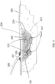
Fig. 3 is a schematic illustration of the wound fromFig. 1 filled with an embodiment of a bespoke wound filler and used in conjunction with a negative pressure treatment system. -
Fig. 4 is a schematic illustration of a wound comprising multiple tissue types being treated with an embodiment of a bespoke wound filler used in conjunction with a negative pressure treatment system. -
Figs. 5A-C are photographs of an embodiment of a repeating building block that may be used as a bespoke wound filler system. -
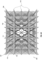
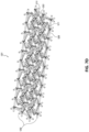
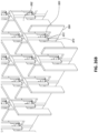
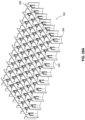
Figs. 6A-D illustrate different views of embodiments of a wound closure device comprising a stabilizing structure. -
Figs. 7A-E illustrate different views and photographs of embodiments of a wound closure device comprising a stabilizing structure. -
Figs. 8A-B are before and after photographs of experiments performed to determine the efficacy of certain embodiments of wound closure devices. -
Figs. 9A-B are before and after photographs of experiments performed to determine the efficacy of certain embodiments of wound closure devices. -
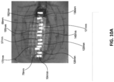
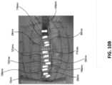
Figs. 10A-B are before and after photographs of experiments performed to determine the efficacy of certain embodiments of wound closure devices. -
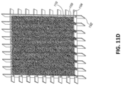
Figs. 11A-E illustrate additional embodiments of a wound closure device comprising a stabilizing structure. -
Figs. 12A-C illustrate an embodiment of a stabilizing structure manufactured from felted foam. -
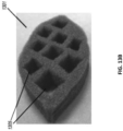
Figs. 13A-B are photographs of further embodiments of wound closure devices comprising a porous wound filler material. -
Figs. 14A-B illustrates an additional embodiment of a wound closure device comprising a stabilizing structure. -
Fig. 15 illustrates an additional embodiment of a wound closure device comprising a stabilizing structure. -
Fig. 16 illustrates an additional embodiment of a wound closure device comprising a stabilizing structure. -
Fig. 17 illustrates an additional embodiment of a wound closure device comprising a stabilizing structure. -
Fig. 18 illustrates an additional embodiment of a wound closure device comprising a stabilizing structure. -
Figs. 19A-B illustrate additional embodiments of wound closure devices comprising a stabilizing structure. -
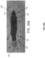
Figs. 20A-B are before and after photographs of experiments performed to determine the efficacy of certain embodiments of wound closure devices. -
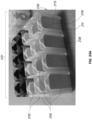
Figs. 21A-B are before and after photographs of experiments performed to determine the efficacy of certain embodiments of wound closure devices. -
Fig. 22 is a photograph of an experiment performed to determine the efficacy of certain embodiments of wound closure devices. -
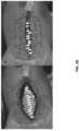
Figs. 23A-B are photographs of experiments performed to determine the efficacy of certain embodiments of wound closure devices. -
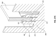
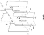
Figs. 24A-E are photographs of various embodiments of stabilizing structures comprising inserts disposed therein. -
Figs. 25A-F illustrate various embodiments of inserts that may be used in stabilizing structures. -
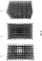
Figs. 26A-F illustrate multiple views of an embodiment of a stabilizing structure. -
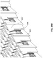
Figs. 27A-D illustrate multiple views of an embodiment of a stabilizing structure. -
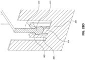
Figs. 28A-E illustrate multiple views of an embodiment of a stabilizing structure. -
Fig. 29 schematically illustrates an embodiment of a stabilizing structure. -
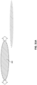
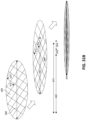
Fig. 30A illustrates a top view of an embodiment of an oval shaped stabilizing structure. -
Fig. 30B illustrates a top view of an embodiment of an oval shaped stabilizing structure with foam. -
Figs. 31A-B illustrate embodiments of methods for closing a wound. -
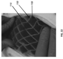
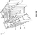
Figs. 32A-C illustrate multiple views of an embodiment of a stabilizing structure. -
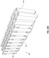
Figs. 33A-G illustrate multiple views of an embodiment of a stabilizing structure. -
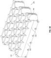
Fig. 34 illustrates one embodiment of a hinged stabilizing structure for closing a wound. -
Fig. 35 illustrates an embodiment of a fully flexible stabilizing structure. -
Fig. 36 illustrates one embodiment of a stabilizing structure for a wound. -
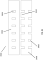
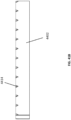
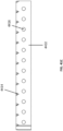
Fig. 37 illustrates an embodiment of a stabilizing structure for a wound cut from a roll. -
Fig. 38 illustrates an embodiment of a stabilizing structure having an oval shape. -
Figs. 39A-F illustrate multiple views of an embodiment of a stabilizing structure. -
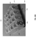
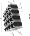
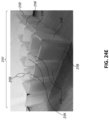
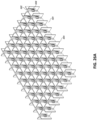
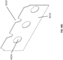
Figs. 40A-D illustrate multiple views of an embodiment of a stabilizing structure comprising openings for fluid passage. -
Figs. 41A-C illustrate multiple embodiments of a stabilizing structure. -
Figs. 42A-B illustrate multiple embodiments of a stabilizing structure comprising windows. -
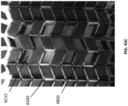
Figs. 43A-C are photographs of various embodiments of a stabilizing structure comprising foam inserts. -
Figs. 44A-B illustrate embodiments of a wound filler comprising stabilizing structures within a porous material. -
Fig. 45 illustrates an embodiment of a ring that can surround a stabilizing structure. -
Figs. 46A-B are schematic illustrations of embodiments of a wound treatment apparatus comprising a bespoke wound filler. -
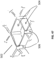
Fig. 47 illustrates an embodiment according to the invention of a repeating building block that may be part of a bespoke wound. -
Fig. 48 illustrates an embodiment of a bespoke wound filler comprising a surrounding lip. -
Figs. 49A-49D illustrates embodiments of securing portions and clips that may be constructed as part of a bespoke wound filler. - Embodiments disclosed herein relate to apparatuses and methods of treating a wound, especially with reduced pressure. Embodiments for use with negative pressure include pump and wound dressing components and apparatuses. The apparatuses and components comprising the wound overlay and packing materials, if any, are sometimes collectively referred to herein as dressings.
- It will be appreciated that throughout this specification reference is made to a wound. It is to be understood that the term wound is to be broadly construed and encompasses open and closed wounds in which skin is torn, cut or punctured or where trauma causes a contusion, or any other superficial or other conditions or imperfections on the skin of a patient or otherwise that benefit from reduced pressure treatment. A wound is thus broadly defined as any damaged region of tissue where fluid may or may not be produced. Examples of such wounds include, but are not limited to, abdominal wounds or other large or incisional wounds, either as a result of surgery, trauma, sternotomies, fasciotomies, or other conditions, dehisced wounds, acute wounds, chronic wounds, subacute and dehisced wounds, traumatic wounds, flaps and skin grafts, lacerations, abrasions, contusions, burns, electrical burns, diabetic ulcers, pressure ulcers, stoma, surgical wounds, trauma and venous ulcers or the like.
- As is used herein, reduced or negative pressure levels, such as -X mmHg, represent pressure levels that are below standard atmospheric pressure, which corresponds to 760 mmHg (or 1 atm, 29.93 inHg, 101.325 kPa, 14.696 psi, etc.). Accordingly, a negative pressure value of -X mmHg reflects absolute pressure that is X mmHg below 760 mmHg or, in other words, an absolute pressure of (760-X) mmHg. In addition, negative pressure that is "less" or "smaller" than X mmHg corresponds to pressure that is closer to atmospheric pressure (e.g., -40 mmHg is less than -60 mmHg). Negative pressure that is "more" or "greater" than -X mmHg corresponds to pressure that is further from atmospheric pressure (e.g., -80 mmHg is more than -60 mmHg).
- The negative pressure range for some embodiments of the present disclosure can be approximately -80 mmHg, or between about -20 mmHg and -200 mmHg. Note that these pressures are relative to normal ambient atmospheric pressure. Thus, -200 mmHg would be about 560 mmHg in practical terms. In some embodiments, the pressure range can be between about -40 mmHg and -150 mmHg. Alternatively a pressure range of up to -75 mmHg, up to -80 mmHg or over -80 mmHg can be used. Also in other embodiments a pressure range of below -75 mmHg can be used. Alternatively, a pressure range of over approximately -100 mmHg, or even 150 mmHg, can be supplied by the negative pressure apparatus. In some embodiments, the negative pressure range can be as small as about -20 mmHg or about -25 mmHg, which may be useful to reduce fistulas. In some embodiments of wound closure devices described here, increased wound contraction can lead to increased tissue expansion in the surrounding wound tissue. This effect may be increased by varying the force applied to the tissue, for example by varying the negative pressure applied to the wound over time, possibly in conjunction with increased tensile forces applied to the wound via embodiments of the wound closure devices. In some embodiments, negative pressure may be varied over time for example using a sinusoidal wave, square wave, and/or in synchronization with one or more patient physiological indices (e.g., heartbeat). Examples of such applications where additional disclosure relating to the preceding may be found include Application Serial No.
11/919,355, titled "WOUND TREATMENT APPARATUS AND METHOD," filed October 26, 2007 US 2009/0306609 ; andU.S. Patent No. 7,753,894, titled "WOUND CLEANSING APPARATUS WITH STRESS," issued July 13, 2010 . - Turning to
Figure 1 , treatment of a wound with negative pressure in certain embodiments uses a negativepressure treatment system 101 as illustrated schematically here. In this embodiment, awound site 110, illustrated here as an abdominal wound site, may benefit from treatment with negative pressure. However, many different types of wounds may be treated by such a method, and the abdominal wound illustrated here is merely one particular example. Such abdominal wound sites may be a result of, for example, an accident or due to surgical intervention. In some cases, medical conditions such as abdominal compartment syndrome, abdominal hypertension, sepsis, or fluid edema may require decompression of the abdomen with a surgical incision through the abdominal wall to expose the peritoneal space, after which the opening may need to be maintained in an open, accessible state until the condition resolves. Other conditions may also necessitate that an opening remain open, for example if multiple surgical procedures are required (possibly incidental to trauma), or there is evidence of clinical conditions such as peritonitis or necrotizing fasciitis. - In cases where there is a wound, particularly in the abdomen, management of possible complications relating to the exposure of organs and the peritoneal space is desired, whether or not the wound is to remain open or if it will be closed. Therapy, preferably using the application of negative pressure, can be targeted to minimize the risk of infection, while promoting tissue viability and the removal of deleterious substances from the wound site. The application of reduced or negative pressure to a wound site has been found to generally promote faster healing, increased blood flow, decreased bacterial burden, increased rate of granulation tissue formation, to stimulate the proliferation of fibroblasts, stimulate the proliferation of endothelial cells, close chronic open wounds, inhibit burn penetration, and/or enhance flap and graft attachment, among other things. It has also been reported that wounds that have exhibited positive responses to treatment by the application of negative pressure include infected open wounds, decubitus ulcers, dehisced incisions, partial thickness burns, and various lesions to which flaps or grafts have been attached. Consequently, the application of negative pressure to a
wound site 110 can be beneficial to a patient. - Accordingly, certain embodiments provide for a
wound contact layer 105 to be placed over thewound site 110. Preferably, thewound contact layer 105 can be a thin, flexible material which will not adhere to the wound site or the exposed viscera in close proximity. For example, polymers such as polyurethane, polyethylene, polytetrafluoroethylene, or blends thereof may be used. In one embodiment, the wound contact layer is permeable. For example, thewound contact layer 105 can be provided with openings, such as holes, slits, or channels, to allow the removal of fluids from thewound site 110 or the transmittal of negative pressure to thewound site 110. Additional embodiments of thewound contact layer 105 are described in further detail below. - Certain embodiments of the negative
pressure treatment system 101 may also use awound filler 103, which may be a bespoke wound filler as will be described in much greater detail below and which can be disposed over thewound contact layer 105 or into direct contact with the wound. Thewound filler 103 shown inFigure 1 is merely illustrative of one configuration of a wound filler that may be utilized, wherein portions of the wound filler may be torn away to appropriately size the wound filler. In some embodiments, the bespoke wound fillers described in greater detail below eliminate the need to provide a wound filler that needs to be cut or sized by the clinician before applying the wound filler into the wound. In certain embodiments, the wound filler of any of the embodiments described herein this section or elsewhere in the specification is applied directly to the wound with or without awound contact layer 105 and/or adrape 107. Thisfiller 103 can be constructed from a porous material, for example foam, that is soft, resiliently flexible, and generally conformable to thewound site 110. Such a foam can include an open-celled and reticulated foam made, for example, of a polymer. Suitable foams include foams composed of, for example, polyurethane, silicone, and polyvinyl alcohol. In certain embodiments, thisfiller 103 can channel wound exudate and other fluids through itself when negative pressure is applied to the wound. Somefillers 103 may include preformed channels or openings for such purposes. Other embodiments of wound fillers that may be used in place of or in addition to thefiller 103 are discussed in further detail below. - In some embodiments, a
drape 107 is used to seal thewound site 110. Thedrape 107 can be at least partially liquid impermeable, such that at least a partial negative pressure may be maintained at the wound site. Suitable materials for thedrape 107 include, without limitation, synthetic polymeric materials that do not significantly absorb aqueous fluids, including polyolefins such as polyethylene and polypropylene, polyurethanes, polysiloxanes, polyamides, polyesters, and other copolymers and mixtures thereof. The materials used in the drape may be hydrophobic or hydrophilic. Examples of suitable materials include Transeal® available from DeRoyal and OpSite® available from Smith & Nephew. In order to aid patient comfort and avoid skin maceration, the drapes in certain embodiments are at least partly breathable, such that water vapor is able to pass through without remaining trapped under the dressing. An adhesive layer may be provided on at least a portion the underside of thedrape 107 to secure the drape to the skin of the patient, although certain embodiments may instead use a separate adhesive or adhesive strip. Optionally, a release layer may be disposed over the adhesive layer to protect it prior to use and to facilitate handling of thedrape 107; in some embodiments, the release layer may be composed of multiple sections. - The
negative pressure system 101 can be connected to a source of negative pressure, for example apump 114. One example of a suitable pump is the Renasys EZ pump available from Smith & Nephew. Thedrape 107 may be connected to the source ofnegative pressure 114 via aconduit 112. Theconduit 112 may be connected to aport 113 situated over anaperture 109 in thedrape 107, or else theconduit 112 may be connected directly through theaperture 109 without the use of a port. In a further alternative, the conduit may pass underneath the drape and extend from a side of the drape.U.S Application Serial No. 10/533,275, filed October 28, 2003 7,524,315 discloses other similar aspects of negative pressure systems. - In many applications, a container or
other storage unit 115 may be interposed between the source ofnegative pressure 114 and theconduit 112 so as to permit wound exudate and other fluids removed from the wound site to be stored without entering the source of negative pressure. Certain types of negative pressure sources-for example, peristaltic pumps- may also permit acontainer 115 to be placed after thepump 114. Some embodiments may also use a filter to prevent fluids, aerosols, and other microbial contaminants from leaving thecontainer 115 and/or entering the source ofnegative pressure 114. Further embodiments may also include a shut-off valve or occluding hydrophobic and/or oleophobic filter in the container to prevent overflow; other embodiments may include sensing means, such as capacitive sensors or other fluid level detectors that act to stop or shut off the source of negative pressure should the level of fluid in the container be nearing capacity. At the pump exhaust, it may also be preferable to provide an odor filter, such as an activated charcoal canister. In further embodiments, the aforementioned wound treatment system may be combined with a fluid source to allow for irrigation of the wound. - In other embodiments, a negative pressure wound therapy apparatus may utilize a canister-less system, such as the PICO system available from Smith & Nephew. In some embodiments, a wound dressing may be provided comprising an absorbent layer such as a superabsorbing material configured to store wound exudate therein. The absorbent layer may be contained between a wound cover or backing layer and an optional wound contact layer, and the entire dressing may include a port configured to be connected to a source of negative pressure. Such dressings may include multiple layers configured to facilitate transmission of negative pressure to a wound site and also to promote flow of fluid into the absorbent layer. Further details regarding wound treatment apparatuses and methods incorporating absorbent materials, transmission layers and other components are found in
U.S. Application Serial No. 10/575,871, filed January 29, 2007 7,964,766 ;U.S. Application Serial No. 12/744,055, filed May 20, 2010 US2011/0009838 ;U.S. Application Serial No. 12/744,277, filed September 20, 2010 US2011/0028918 ;U.S. Application Serial No. 12/744,218, filed September 20, 2010 US201110054421 U.S. Application Serial No. 13/092,042, filed April 21, 2011 US2011/0282309 ;U.S. Application Serial No. 11/432,855, filed May 11, 2006 7,615,036 ;U.S. Application Serial No. 11/610,458, filed December 13, 2006 7,779,625 ;U.S. Application Serial No. 12/592,049, filed November 18, 2009 8,460,255; PCT Application No.PCT/US13/53075, filed July 31, 2013 , titled "WOUND DRESSING AND METHOD OF TREATMENT";U.S. Application Serial No. 11/517,210, filed September 6, 2006 7,569,742 ;U.S. Application Serial No. 11/516,925, filed September 6, 2006 7,699,823 ;U.S. Application Serial No. 11/516,216, filed September 6, 2006 US2007/0055209 . -
Figure 2 illustrates awound 201 that may require filling with a bespoke wound filler so as to appropriately treat and heal the wound. Preferably, thewound 201 will be treated with negative pressure. The margins and contours of thewound 201 as illustrated are irregular, rendering it difficult to fill the wound with conventional fillers. -
Figure 3 illustrates thewound 201 having abespoke filler 203 inserted therein. Preferably, a liquid-impermeable drape 205 is placed over the wound and sealed against skin proximate the wound margins, for example with an adhesive. Anaperture 206 may be made into thedrape 205 so as to provide a fluidic connection to a source of negative pressure (not illustrated) such as a vacuum pump. Preferably, theaperture 206 communicates with a fluidic connector orport 207, which may be attached to the source of negative pressure via aconduit 208. Further details regarding negative pressure systems, apparatuses and methods that may be utilized with the systems, apparatuses and methods described herein are found in U.S. Application Serial No.13/381,885, filed December 30, 2011 US2012/0116334 ;U.S. Application Serial No. 12/886,088, filed September 20, 2010 US2011/0213287 ;U.S. Application Serial No. 13/092,042, filed April 21, 2011 US2011/0282309 . -
Figure 4 illustrates an example of abespoke wound filler 203 used in conjunction with awound 201. Adrape 205 is placed over thewound 201 and sealed (e.g., using an adhesive) against the surrounding skin near the wound margins. Preferably, anaperture 206 through thedrape 205 communicates with a source of negative pressure (not illustrated), and aport 207 may be used as a fluidic connector between the wound and the source of negative pressure. Aconduit 208 may communicate with the source of negative pressure and the wound. UnlikeFigure 3 , thewound 201 inFigure 4 comprises different tissue anatomy, including exposedbone areas 212, in addition tosoft tissue areas 214. Of course, other tissue types may be present, including for example muscles, nerves, ligaments, tendons, or any other tissue that may become exposed within a wound. According to some embodiments described herein this section and in greater detail below, thebespoke wound filler 203 is customized to the size and environment of thewound 201. Thewound filler 203 illustrated here therefore comprises a first contactingarea 222 configured to contact the exposedbone areas 212 and a second contactingarea 224 configured to contact thesoft tissue areas 214. In some embodiments, the first contactingarea 222 may be occlusive, substantially fluid-impermeable, or have few to no pores , so as to limit the amount of fluid removed from and negative pressure applied to, the exposedbone area 212. In some embodiments, conversely, the second contactingarea 224, when configured to contact thesoft tissue areas 214, may be configured to be porous so as to enhance fluid removal and granulation tissue growth upon application of negative pressure. In some embodiments, theinterior body 226 of thebespoke wound filler 203 may be of a different porosity than other areas; preferably, it comprises a material with greater porosity or larger pores than the wound-contacting surfaces. Such configurations may be preferable to enhance fluid removal, because, since the larger pores are not in contact with thewound 101, granulation tissue from thewound 101 will not grow into the larger pores. - In certain embodiments, it may be desirable to limit granulation tissue formation while still allowing fluid to be drawn away via very fine holes or slits. For example, holes or slits may have a diameter of at most about .1 µm, .5 µm, 1 µm, 2 µm, 5 µm, 10 µm, 15 µm, 20 µm, 30 µm, 40 µm, 50 µm, 75 µm, 100 µm, 125 µm, 150 µm, 175 µm, or 200 µm. Suitable materials for contacting tissue and maintaining porosity may include Elastollan (from BASF) or other materials as described herein this section or elsewhere in the specification. Further suitable materials include thermoplastic polyurethanes that are generally non-toxic and suitable for wound fillers.
- Generally, the
bespoke filler 203 may be constructed so as to provide a bespoke or custom fit into awound 201. As will be described in greater detail below, various attributes of the bespoke filler may be modified, including its dimensions, density, material characteristics (including the use of multiple materials), physical characteristics, chemical characteristics, molecular delivery mechanisms, structural characteristics, and other attributes. In some embodiments, portions of the bespoke wound filler may have characteristics favorable to the application of negative pressure. In certain embodiments, the bespoke wound filler may have characteristics that are favorable to the application of irrigation. - The general shape and configuration of the
bespoke filler 203 is preferably determined in relation to the shape and volume of thewound 201. The shape and volume of thewound 201 may be determined by any suitable method, but is preferably done by creating a three-dimensional (3D) scan of thewound 201. Although reference to 3D scans and/or 3D modeling is made herein this section and throughout the specification, 2D scanning or 2D modeling may also be used in place of the 3D scans and/or 3D models. - Preferably, a device capable of obtaining a 3D scan of the
wound 201 is used that does not make contact with the wound. Such devices include laser scanners (particularly laser scanners employing triangulation techniques), stereo-optical scanners, or cameras with depth sensors such as those used in the Microsoft XBOX Kinect®. Other suitable devices include 3D Systems' ZScanner® 800. Preferably, the 3D scan device is capable of scanning a wound to an accuracy of at least about: 1 µm, 5 µm, 10 µm, 20 µm, 30 µm, 40 µm, 50 µm, 60 µm, 70 µm, 80 µm, 80 µm, or 100 µm. In some embodiments, other methods of obtaining a scan may be used such as deriving a scan from an analog or digital image of the wound. - 3D scans may also be generated via CT or MRI images, for example by "stacking" multiple images together to form a 3D model. In certain embodiments, devices that contact the wound (e.g., via a pressure sensitive stylus), may also be used. In other embodiments, physical molds of the wound may be used to create a 3D scan. These physical molds may be fabricated from any suitable material such as Jeltrate or other alginate or silicone based materials often used for taking dental impressions.
- In some embodiments, the tissue is stained with various markers that can be used to generate a more accurate 3D model. For example, the wound may be stained with markers that identify particular cell types that may be present at the wound site such as the various host cells of the patient or bacterial cells. Cell markers may give an improved overall understanding of the wound by indicating the different stages of healing of various areas of the wound or by providing information relating to infection. Additional markers may be used to stain extra-cellular matrix proteins, thus providing information about the surrounding structure and state of healing in the wound. Stained tissue can be imaged and analyzed via any suitable imaging technique, such as fluorescence microscopy or other techniques. However, imaging of a stained wound is not limited to microscopic techniques and may be performed via any suitable technique. Preferably, the characteristics data collected from staining the wound may be incorporated in the 3D model of the wound, matching particular stained areas to particular regions of the model.
- Assorted hardware and software necessary to interpret and generate a 3D scan, and that is usually provided with the devices, may also be used. Such hardware and software may preferably be configured to interface with a personal computer. Some embodiments may also provide for a miniaturized and/or self-contained 3D scanning device that comprises integrated software and/or hardware.
- In some embodiments, the 3D scanning device may be configured to interface with a telephone or tablet computer. Some embodiments may also provide for a patient to generate a 3D scan themselves (e.g., by using a Kinect® sensor), sending or uploading the 3D scan or model to a service provider, and having the service provider create and send a
bespoke wound filler 203 customized to the patient's particular wound. - The 3D scanning device will preferably generate a 3D wound model of the volume of the wound space using appropriate software. Such a 3D wound model is then modified to include a 3D model of the appropriate wound filler. Suitable software includes Solidworks, Solid Edge, and other 3D CAD programs. In certain embodiments, such 3D data sets of the wound surface volume are generated by subtracting the data set for the wound scan away from a volume larger in overall dimensions than the wound volume dimensions. Some embodiments may provide for the generation of an inverse of the scan surface volume. The data files generated may be in STL, STEP, IGES file formats, other 3D model file types, plain text files, or any suitable file format. The words "3D model" may be generally used throughout the specification to describe a 3D model of the wound alone, a 3D model of the filler alone, a 3D model of the wound with filler, or a 3D surface model of the wound surface. In some embodiments, 3D models may include polygonal mesh, voxel, solid body files, or any other suitable 3D modelling file. The models may be interchangeable between various formats. For example, when using CT scan data generated as a DICOM (Digital imaging and Communications in Medicine) data set, the tissue structures that form the wound may first be selected using a contrast threshold or through manual selection of particular tissue structures. In embodiments, the selected tissue may then be exported into a Mesh file, e.g. STL format. Following tissue selection and exportation, the data may be further filtered and modified to, for example: remove/add holes/folds, add/remove surface texturing, smooth the data set, or provide any other suitable modification. A solid body model may then be generated from this initial modified data mesh. In certain embodiments, this solid body may then be used to subtract from a solid body slightly larger than the wound in dimensions to create an exact solid body of the wound void. The use of any of the above-mentioned types of models is applicable to any of the embodiments described herein this section and elsewhere in the specification.
- Preferably, the software program will modify and/or normalize the 3D wound model obtained from the 3D scanning device so as to make it usable in 3D printing devices (as described below). For example, the software program may modify the 3D model to make the mesh manifold, remove inverted normals, and optimize detail sizes, wall thicknesses, and orientations for use in the 3D printing device. Additionally, the software will preferably make the top of the 3D model flush with the surrounding skin, although in some embodiments, it may be preferable for the bespoke filler (and consequently, the 3D filler model) to extend above the skin at least in part.
- At this stage, attributes of the 3D model may also be modified to account for various factors in the wound environment or to account for particular treatment modalities. A wound will typically contain multiple regions that may be in different stages of healing. For example, a wound may have areas that: are exudating heavily, are infected, are bleeding, contain dead/dying tissue, are drying, are inflamed, or in various other states. Further, the different areas of the wound may comprise different types of tissue, such as bone, cartilage, blood vessels, skin, fat, or any other organs or tissues. To effectively treat these variable tissue types and conditions may require different types of fillers with different physical and chemical characteristics as will be described in greater detail below.
- The use of negative pressure in combination with various wound fillers has been demonstrated to effectively improve wound healing. However, such a combination is most effective when the wound filler is tailored to most effectively apply negative pressure to a particular type of wound. For example, as is described herein this section and elsewhere in the specification, a filler with a desired porosity may allow for an increased volume of fluid to be drawn from a wound at a greater rate. Additionally, as will be described in greater detail below, wound fillers may be tailored to more effectively deliver irrigant fluid to a wound. The fillers may also be tailored to collapse under negative pressure in a manner consistent with the direction of closure of the wound. Further details regarding the collapse of wound fillers under negative pressure will be described in greater detail below, particularly in relation to wound closure devices and stabilizing structures of
Figures 6A-44B . In some embodiments, the wound fillers described above may collapse in any manner described with respect to the closure devices and stabilizing structures ofFigures 6A-44B . - In some embodiments, as described elsewhere in the specification, internal manifolds may be 3D printed within the filler to deliver fluid to the wound bed. For example, a port may be printed on the exterior of the wound filler configured to connect to hot a suction tube and an irrigant tube. The port may in turn be connected to internal manifolding that connects the port to the various surfaces of the wound filler, such as the surface in contact with tissue. For example, the internal manifold may connect the port to the bottom surface and or the side surfaces. In certain embodiments, the fluid manifold may encompass at least about 10% of the total volume of the bespoke wound filler, at least about 20%, at least about 30%, at least about 40%, at least about 50%, at least about 60%, at least about 70%, at least about 80%, at least about 90%, or about 100%.
- For example, and as described in further detail below, attributes of the 3D model may be modified to account for different tissue types in the wound, such as exposed bone or tendon, and which may require that the wound filler be different from wound filler to be used in the treatment of epidermal, sub-epidermal, or muscle tissue.
Figure 4 , as described above, describes such an embodiment. - In some embodiments, a human may assist in the creation of a 3D model, leading to the construction of a bespoke wound filler, by identifying the properties of the various regions of the wound. Hereinafter the word "clinician" will be used to describe any human involved in the creation of the filler, however "clinician" is not limited to only medical practitioners, but could be a home user, general caregiver, or patient.
- The clinician may contribute to the creation of a 3D model for a desired wound filler by identifying the characteristics of the various regions of a wound which may be treated with the wound filler, for example while under negative pressure. For instance, a clinician may identify areas as highly exudating, drying, infected, or having any other condition described herein this section or elsewhere in the specification. A clinician may further identify the tissue type of the various regions of the 3D model. The clinician can identify and define characteristics of the wound such as the shape of the wound, severity of the wound, expected closure of the wound, or any other relevant characteristic of the wound. The clinician may further identify the fluid modality of a particular area of a wound, such as by identifying the level of fluid release from such a portion of the wound. Additionally, the clinician can further identify areas of the wound that would be best served by the application of various levels of negative pressure. Further, the clinician may identify areas that would be best served by irrigation and/or the delivery of various molecules. In addition to the characteristics already described, a clinician may identify any other key characteristics that may influence the healing and closure of a wound or impact the health of a patient.
- Identification of the characteristics of a wound can be performed in a variety of ways as described herein this section and elsewhere in the specification. In some embodiments, the wound is assessed by visual inspection of the wound via computer or human recognition. In certain embodiments, the assessment of the wound is completed using chemical, physical, auditory, or energy-based assays or imaging techniques. In further embodiments, any suitable identification techniques may be used.
- In further embodiments, the clinician may also assess additional health-related factors of the patient and incorporate those factors into the 3D wound model. For example, the clinician could identify a diabetic patient, and recognize that their circulation may be compromised. Thus, the wound model could be altered to account for poor circulation. In other embodiments, a clinician could recognize that a patient may be immune compromised or have other relevant health conditions that may affect wound therapy treatment. The clinician may use these health-related factors to modify the 3D model in any suitable manner. In other embodiments, instead of or in additional to the clinician's contribution to the model, the scanning software can automatically generate a 3D model of the wound by automatically identifying the properties of the various regions of the wound as any of the tissue types or characteristics described herein. Additionally, the 3D model may be modified automatically by a computer algorithm based on the general health characteristics of the patient. Generally, any task described herein this section or throughout the specification as to be performed by a clinician may also be automated to be performed via a computing or generally automated process.
- In some embodiments, the characteristics of the wound can be translated into data points that correspond to spatial points within the 3D model. Thus, spatial points of the 3D wound model may have corresponding wound characteristic data. Such wound characteristic data then may be used as a basis to modify the wound model to build in a corresponding wound filler model or to create a separate, independent wound filler model.
- As described herein this section and elsewhere in the specification, a 3D wound filler model suitable for 3D printing or other custom means of fabrication can be generated from the 3D model of the wound. However, the 3D model of a wound filler need not be generated from a 3D model of a wound. Instead the 3D model of the wound filler can be designed manually by a clinician with assigned characteristics as needed. The clinician may use their assessment of the wound to identify and define particular regions of the wound filler to correspond with characteristics of the wound. In preferred embodiments, the wound filler is designed to facilitate the application of negative pressure to the wound and/or to irrigate the wound. In certain embodiments, the clinician may consider the long term closure of the wound in designating the characteristics of the wound filler. For example, the clinician may construct the 3D model with the direction of closure in mind, such as by aligning the closure along the Langer lines or along a shorter axis of the wound.
- As is described herein this section and elsewhere in the specification, the 3D wound filler model is comprised of various regions that may have variable physical, chemical, and structural characteristics as is desired to treat the wound. The physical, chemical, and structural characteristics of the wound filler model can be determined from the corresponding characteristics of the 3D wound model or via any process as described herein this section or elsewhere in the specification. In some embodiments, the physical, chemical, and structural characteristics of the wound filler model can also be assigned. The different regions may have significant structural differences or utilize different materials as is appropriate for treatment of a wound. The different regions may have various chemical properties as is desired for proper treatment of a wound. In preferred embodiments, the different regions of the wound filler are tailored for the application of negative pressure as is desired for wound healing. In some embodiments, the 3D wound filler model is generated automatically based on characteristics of the wound, while in other embodiments the 3D wound filler information is input manually.
- In certain embodiments, a 3D model of the wound filler is created merely from the spatial data contained within the 3D wound model. Such an embodiment may generate a wound filler that accommodates the width, length, and appropriate depth of a wound and could be desirable for the treatment of an irregularly shaped wound as described above. In preferred embodiments, the 3D model of the wound filler is created from multiple different wound characteristics that were incorporated into the 3D model of the wound. The 3D model of the wound filler may also be further determined by the general health-related characteristics of the patient.
- As described above, in some embodiments, the characteristics of the various regions of the wound filler may be determined by the anatomical location of the wound and the surrounding tissues. For example, a wound filler used for the treatment of an abdominal wound may comprise a slit structure. In another example, a region of a wound filler associated with a bone or tendon could be constructed from a hydrophilic material with a reasonably closed cell structure so as to maintain moisture in the surrounding tissue. In some embodiments, a fine pore size in the range of about 10-350µm may be used to maintain moisture. Such a pore size may range from at least about 1 µm, 5 µm, 10 µm, 15 µm, 20 µm, 30 µm, 40 µm, 50 µm, 75 µm, 100 µm, 125 µm, 150 µm, 200 µm, 300 µm, 400 µm., 500 µm, or more than 500 µm In still another example, the wound filler region in the area of a pressure ulcer or highly exudating tissue may incorporate an open structure such as a reticulated foam so as to better remove liquid from the tissue. In some embodiments, a larger pore size in the range of about 350-900µm may be used to aid in liquid removal. Such a pore size may range widely, for example from at least about 10 µm, 50 µm, 100 µm, 200 µm, 300 µm, 400 µm, 500 µm, 1000 µm, 2000 µm, 3000 µm, 4000 µm, or 5000 µm. In some embodiments, any of the pore sizes disclosed in PCT Application No.
PCT/GB2012/000489, titled "WOUND CONTACTING MEMBERS AND METHODS," filed June 7, 2012 - In certain embodiments, as described above, characteristics of the various regions of the wound filler may be determined automatically based on the 3D wound model or could be assigned. In some embodiments, the characteristics may include water/vapor permeability, gas permeability, absorption capacity, thickness, material type, material structure (such as number of layers), thickness/size, presence of pharmacological additives, color, hydrophobicity/hydrophilicity, or any other suitable characteristic.
- The various regions of the wound filler such as determined by the 3D wound model may comprise different materials or have different structural characteristics. In non-limiting embodiments, regions of the wound filler may be comprised of: various rigid, semi-rigid, or soft foams; various hydrophilic and/or hydrophobic foams; soft, conformable, and preferably resiliently flexible materials such as polymers, including thermoplastics; various biodegradable materials; cellulose materials, superabsorbers, or other suitable materials. Suitable polymers include ABS synthetic rubbers, various silicones such as Integra, polyurethanes such as the Elastollan series Thermoplastic polyurethane elastomers (TPUs) from BASF and specifically the Elastollan series hydrophilic TPU, ethylene vinyl acetate, nylons for example Nylon 618 from Taulman 3D Missouri, polyamides, and polyethylenes. The Tangoplus family of resins, e.g. Tangoplus FC930, from Stratsys have varying levels of hardness so that structures with different degrees of flexibility and compression can be fabricated. Further examples of possible materials include 3D knit spacer fabrics such as those manufactured by Gehring Textiles. In further embodiments, the material may comprise polylactic acid (PLA), polyglycolic acid, or any other material disclosed herein this section or elsewhere in the specification. The wound filler may also include anistropic materials such as the coil-like materials found in
U.S. Patent Serial No. 10/981,119, filed November 4, 2011 - As described herein this section and elsewhere in the specification, in some embodiments, the wound filler may have varied structural characteristics such as porosity. In a preferred embodiment, the 3D printer (described further below) may control the porosity of the resulting material, either in the bespoke filler as a whole or by varying the porosity through different sections of the device. For example, a wound filler with smaller pores may be preferable to minimize tissue growth or adhesion, while larger pores may be useful to promote removal of wound exudate from the wound. Such a configuration may thus comprise, for example, a material with smaller pores in contact with the wound which encapsulates or is placed underneath a material with larger pores. As described above and elsewhere in the specification, the pore size may vary considerably, such as between about .1 to 200 µm. Preferably, smaller pores may measure between about 20 to 150µm, while larger pores may measure between 400-3000µm or greater. Still other pores may measure less than about 20 µm, less than about 1 µm, less than about .5 µm, or between about 150 to 400µm. In another example, porosity may be reduced in applications where scar tissue (resulting from excess granulation tissue) should be minimized. In some cases, the number of pores per unit area may be reduced, for example, some embodiments may provide for a wound contacting layer of the bespoke wound filler having an open area of approximately 20%, and 1 mm diameter pore sizes. In certain embodiments, other structural characteristics may be varied within the material, such as to make the material open-celled with interconnected cavities within the material and/or closed-celled. The structural characteristics of the wound filler are limited only by the capabilities of the 3D fabrication device, and thus all manner of structures and shapes suitable for wound treatment may be used.
- In some embodiments, the wound filler is tailored for the application of negative pressure. As described above in relation to
Figure 4 , and elsewhere in the specification, the wound filler may be designed to have various levels of porosity. In some embodiments, the porosity may be varied to promote liquid flow from portions of the wound via the application of negative pressure. To better control the application of negative pressure, portions of the bespoke wound filler may be made to cover portions of the anatomy from which minimal or no fluid removal is desired. For example, some tissue types, such as exposed bone or tendon, may dry out or be adversely impacted due to the application of negative pressure therapy. Manufacturing a bespoke wound filler that has minimal or no pores when placed over such tissue anatomy may thus be advantageous. Preferably, the bespoke wound filler is manufactured so that other parts of the tissue anatomy in that same wound that would benefit from a porous wound filler (e.g., epithelial tissue) are in contact with a material that has increased porosity. - In addition to altering the porosity of the wound filler to accommodate the desired application of negative pressure, the wound filler may contain flow channels that direct wound exudate drawn via negative pressure. Such flow channels may be oriented horizontally through the wound filler and/or may be oriented vertically. Regions of the filler where limited or no negative pressure is desired may have few if any channels. In certain embodiments, the material characteristics of the wound filler may also be further tailored to accommodate negative pressure such as by using hydrophobic materials like hydrophobic foam to allow for the application of negative pressure without trapping fluid. In some embodiments, hydrophilic materials may be used to trap wound exudate drawn from the surrounding wound tissues. The hydrophilic materials may be superabsorbers. The various regions of the wound filler may be open celled, closed celled, or a combination of the two as is needed to apply desired levels of negative pressure. In some embodiments, particular regions of the wound filler may be constructed as wicking layers to wick fluid in a desirable manner. As described herein this section and elsewhere in the specification, different regions of the wound filler may have different functions and properties, such that the application of negative pressure to various areas of the wound can be well controlled.
- In some embodiments, the bulk of the wound filler comprises open-celled hydrophobic material to allow for fluid flow via the application of negative pressure. In certain embodiments, this significant bulk of open-celled hydrophobic material may be surrounded by other materials suited for more direct contact with the wound tissues.
- In particular embodiments, as will be described in much greater detail below in relation to
Figures 6A-44B , the wound filler may be tailored to collapse more readily in one direction than in another direction. As described elsewhere in the specification, the wound filler may collapse more readily in a horizontal direction while remaining relatively rigid in the vertical direction. It will be recognized by one of skill in the art that "horizontal direction" may refer to a plane parallel to the plane of the wound, while vertical direction may refer to a plane perpendicular to the plane of the wound. It will further be recognized by one of skill in the art, that such a wound filler may collapse under negative pressure horizontally within the wound in a direction perpendicular to the longitudinal axis of the wound, while remaining substantially rigid in the vertical direction. In certain embodiments, particular regions of the wound filler may collapse, while other regions remain rigid. - In some embodiments, the 3D wound filler may be tailored for the application of irrigation to the wound. In certain embodiments, the wound filler is connected to one or more reservoirs containing irrigant fluid. Such irrigant fluid may contain antimicrobial molecules, anti-inflammatory molecules, marking molecules, or growth factors that promote wound healing. Irrigant fluid may be applied simultaneously with the application of negative pressure, such that simultaneous irrigation and aspiration is possible. In other embodiments, aspiration then irrigation or irrigation then aspiration are sequential.
- The use of irrigation may be desirable for certain regions of the wound, thus the wound filler may be tailored to best apply irrigation to those regions of the wound. For example, in drier areas of the wound or in areas requiring debridement via irrigation, the wound filler may be configured to allow greater irrigant flow to the wound. Such an application may include wound filler regions comprising flow channels, such as those described above in relation to negative pressure, that direct fluid flow towards specific portions of the wound. In other embodiments, regions of the wound filler directed towards irrigant flow may be more porous or be open-celled, thus allowing for greater flow of irrigant fluid. In areas of the wound where irrigation is less desirable, portions of the wound filler may be made to be more occlusive, with smaller or nonexistent pores, or a closed-cell structure. Such features are applicable to any manifold disclosed herein this section or elsewhere in the specification.
- In some embodiments, the 3D wound filler model may be constructed such that the filler has different layers of material and structure. For example, in a penetrating wound, the filler may have layers of softer material deeper in the wound, with layers of more rigid material closer to the uppermost surface of the wound, thus allowing for the deeper portions of the wound to close before the portions of the wound that are closer to the exterior. In some embodiments, the central portion of the filler may be comprised of one material and/or structure while an exterior portion is comprised of a different material and/or structure. In further embodiments, the wound filler may be layered similar to an onion, with various layers with differing material or structural properties surrounding one another. In further embodiments, the layers may be oriented in a vertical manner such that each layer comprised a flattened section in the horizontal plane.
- As described above in relation to the design of the wound filler,
Figures 5A-C illustrate different views of awound filler 302 which may comprise an anisotropic structure having a first compressive response along a first axis and a second compressive response along a second axis perpendicular to the first axis, the second compressive response being different from the first compressive response. In one embodiment, this structure may be nonabsorbent, and may comprise stacked, coil-like repeatingunits 302. This and other embodiments of wound fillers may be manufactured by the 3D printer with reference to a 3D model, and examples of such may be found in the'937 patent. The materials described in the '937 patent have anisotropic properties, meaning that their material properties may be dimensionally dependent. For example, as described above, an anisotropic material may have increased stiffness in one direction versus another direction. Thus, a material with anisotropic properties such as those depicted in the '937 patent may collapse more readily in one direction rather than another. Such a material could be used within the wound to control the compression of the wound filler in particular directions and preferentially compress the filler to allow for improved wound closure. The material of the '937 patent is nonabsorbent, thus this material may allow for the passage of negative pressure. In some embodiments, the material of '937 may further be used in combination with negative pressure strategies to direct the application of negative pressure and wound closure, in a manner consistent with the embodiments described herein this section and elsewhere in this specification. - The materials that comprise the wound filler may be determined by the characteristics of a particular region of the 3D wound model or may be assigned. For example, an area of the wound that requires additional hydration could utilize a moist hydrophilic material such as a hydrogel. An area that is highly exudating may need to be highly absorbing and have a high water vapor evaporation. Areas with low levels of wound exudate may require a nonabsorptive material with low water vapor permeability so as to trap moisture.
- Since a 3D printer is capable of printing a wide variety of shapes, in some embodiments, the 3D model may also include a port and/or tubing such that the wound filler may be connected to a source of negative pressure. In further embodiments, the 3D model includes additional suitable articles that may be useful for wound healing.
- In some embodiments, the material may be configured as a scaffold material to promote tissue ingrowth and/or bioabsorption. For example, bioabsorption can be achieved by using polyglycolic or polylactic acids or co-polymers of these polymers, for the printing of the scaffold, and which then may be seeded with cells and/or cell growth promoters. Antibiotics, anti-inflammatory drugs, diagnostic agents such as radioopaque markers, and other such materials may also be incorporated therein. The scaffold material may be tailored to deliver a variety of molecules in the form of controlled delivery. For example, one region of the filler could deliver an antimicrobial molecule to an infected region of tissue, while another region of the filler delivers an anti-inflammatory molecule to an inflamed region of tissue. Various molecules may be released in to the surrounding tissue as is merited by the characteristics of the surrounding tissue. Released molecules are not limited only to locally acting molecules, in some embodiments systemically acting drugs may be released.
- The wound filler is not limited to one continuous, intact structure. The wound filler can be constructed to be in separate pieces and applied separately to the wound rather than as a single unit. It should be understood that all embodiments described herein this section or elsewhere in the specification may be generated as a single continuous structure or as separate dividable portions. This approach is particularly useful for dealing with undetermined structures of wounds or tunneling wounds where it may not be possible to insert a single wound filler
- In some embodiments, the wound filler may be constructed as a rounded bowl-like shape, or may comprise a rounded bowl-like shape at the bottom of the filler. This bowl-like shape can be a comprised of a single material layer such as a foam bowl. In certain embodiments, the bowl comprises one material while a remainder of the wound filler positioned above or within the bowl comprises a different material. In some embodiments the bowl portion of the filler may be in the form of a divided separate section of the wound filler.
- Having generated the 3D model, the 3D model can be used by a 3D printing device to manufacture the bespoke wound filler. The 3D printing device may be any suitable 3D printer, including by means of example only the Objet Connex500™, the 3D Systems ZPrinter® 850, or the RepRap. In other embodiments, wound filler fabrication may be performed using any known wound dressing fabrication technique. The wound filler may be fabricated from any materials described herein this section or elsewhere within the specification, or any other type of suitable material. The wound filler may be fabricated to comprise any structure described herein this section or elsewhere within the specification, or any structure that may be suitable for the wound filler. The wound filler may be fabricated to comprise any characteristic described herein this section or elsewhere within the specification, or any characteristic that may be suitable for the wound filler.
- In some embodiments, the wound filler may be fabricated separately from the wound and later placed within the wound. In other embodiments, the wound filler may be created directly in the wound. In still other embodiments, a portion or portions of the wound filler may be created separately from the wound, while a portion or portions of the wound filler may be created directly in the wound.
- As described above, the wound filler may be fabricated via any known fabrication technique. In some embodiments, the wound filler may be fabricated via extrusion or via electrospinning techniques. The wound filler can also be fabricated via gas blowing or localized deposition directly into the wound or onto a substrate.
- In some embodiments, the outermost or topmost layer of the wound filler can be comprised of a fluid impermeable polymer, such as silicone. This outermost or topmost layer can overlay the top of the wound filler and extend beyond the edges of the wound. This outermost or topmost layer can further comprise an adhesive or other means for sealing the outermost layer around the wound. In this manner, the outermost layer may function as a drape to contain the application of negative pressure. In some embodiments this outermost or topmost layer may be fabricated in combination with a biodegradable wound filler such that once the wound filler biodegrades, the outermost layer is still intact. Similar to the above description of the materials utilized in the design of the wound filler, the 3D printer is configured to manufacture a bespoke filler from soft, conformable, and preferably resiliently flexible materials such as polymers, including thermoplastics. Suitable polymers include ABS synthetic rubbers, polyurethanes for example Elastollan SP9109 from BASF, nylons for example Nylon 618 from Taulman3D Missouri, polyamides, ethylenevinyle acetates, and polyethylenes. The Tangoplus family of resins, e.g. Tangoplus FC930, from Stratsys have varying levels of hardness so that structures with different degrees of flexibility and compression can be fabricated. In further embodiments, the materials utilized to construct the wound filler and other components of the wound treatment system encompass all materials disclosed in this section and elsewhere in the specification.
- As described above in relation to the design of the wound filler, in some embodiments, the 3D printer may be capable of depositing materials or using materials that form a porous configuration. In some embodiments, the materials may be harder, and may include porous scaffolding materials such as hydroxyapatite that promote tissue growth. The 3D printer may be configured to use multiple materials so as to form a bespoke wound filler composed of multiple devices. In some embodiments, the 3D printer is capable of manufacturing a bespoke wound filler consisting of a repeating building block, for example the building blocks described herein this section and elsewhere in the specification.
- Some embodiments may also provide for regions of the wound filler to be constructed from repeating building blocks. The use of repeating building blocks may be advantageous during manufacture because these building blocks could be replicated over and over again within the model allowing for an easier and more efficient creation of structures within the filler. Further, the use of building blocks may allow for the 3D fabrication device and/or the associated software to operate more efficiently. For example, the use of building blocks may allow the fabrication device to move through tight, specified patterns and limit the required movement and energy consumption of the device. In some embodiments, the repeating unit may be comprised of any physical, chemical, or structural characteristics as described herein this section or elsewhere in the specification. Different regions of the wound filler may be comprised of different building blocks, allowing for a complex construction of layered and/or stacked building blocks of different types. For example, one region comprising a repeating building block may utilize building blocks of foam having a desired porosity, structure or other characteristics. A second region may comprise repeating building blocks made from a different material such as the coil-like material described in '937 patent and depicted as 302 in
Figures 5A-C . Based on the 3D model, repeating blocks may have different characteristics for positioning in different parts of the wound. The software for the 3D printer or other fabrication device may set the contours of the 3D model as the limits for a repeating building block and repeat the building block in three dimensions until it reaches the limit of a contour. - Preferably, for small details, the 3D printer can manufacture details in a range of at least about: .1 µm, .5 µm, 1 µm, 2 µm, 5 µm, 10 µm, 15 µm, 20 µm, 25 µm, 30 µm, 35 µm, 40 µm, 45 µm, 50 µm, 55 µm, 60 µm, 65 µm, 70 µm, 75 µm, 80 µm, 85 µm, 90 µm, 95 µm or 100 µm. Details between 30-50µm may be conducive to obtaining good tissue growth. In some embodiments, the 3D printer is configured to manufacture bespoke wound fillers as detailed in PCT Application
PCT/GB2012/000489, filed June 7, 2012 WO20122168678 - With reference to
Figure 47 , some embodiments may also provide for the wound filler to be constructed from a repeating building block or identical cells, for example thebuilding block 502. The 3D fabrication software may thus set the contours of the 3D model as the limits for a repeating building block and repeat the building block in three dimensions until it reaches the limit of a contour. In some embodiments, the repeating building block may be thebuilding block 502, which according to the invention comprises straight sections orwalls 504, preferably constructed from a rigid polymer, joined together by hingedsections 506, preferably constructed from a flexible or soft polymer. Other embodiments not according to the invention of repeating building blocks or cells may be of any of the structures wound filler structures described herein this section or elsewhere in the specification. For example, the stabilizing structures, wound closure devices, or other structures described in relation toFigures 5A-44B may be used. - In certain embodiments, the wound filler may comprise a single horizontal layer of identical cells. In particular embodiments, the wound filler can comprise a plurality of horizontal layers, each layer comprising identical repeating cells. In some embodiments, repeating cells in a first horizontal layer are different from repeating cells in a second horizontal layer above the first horizontal layer. In some embodiments, the wound filler may comprise a first plurality of identical repeating cells and a second plurality of identical repeating cells, wherein the first plurality of identical repeating cells is different from the second plurality of identical repeating cells. At least some of the repeating cells may comprise side walls with an opening extending therethrough, such as shown in
Figure 47 . In some embodiments, at least some of the repeating cells can comprise a first portion with a first stiffness and a second portion with a second stiffness different from the first stiffness. For example, the first portion may be an outer portion (such as formed by thewalls 504 inFigure 47 ) surrounding a second portion within thewalls 504. - Some embodiments, may call for the bespoke wound filler to comprise a porous material. In any of the embodiments described herein, the bespoke wound filler may comprise at least one region comprising a porous material suitable for channeling wound exudate from a wound site and negative pressure to the wound site, and a more rigid stabilizing structure at least partially embedded within the porous material.
- In some embodiments, the bespoke wound filler may be fabricated from a polymer. In some embodiments, an apparatus such as those described previously, may further comprise a drape configured to be placed over the bespoke wound filler and be sealed to skin surrounding the wound. In embodiments, a port may be configured to connect the drape to a source of negative pressure. In certain embodiments, a source of negative pressure may be configured to apply negative pressure to the wound filler under the drape.
- Some embodiments may provide for the entirety of or regions of the bespoke wound filler to be constructed with a shape, configuration or including components of stabilizing structures and wound closure devices such as those described below in relation to
Figures 6A-44B and47 , however, only the embodiment offigure 47 is according to the invention. The stabilizing structures and wound closure devices, as described herein this section or elsewhere in the specification, may therefore be made as bespoke wound fillers utilizing the methods and apparatuses described herein. Many of these stabilizing structures and wound closure devices include identical repeating units or cells that may constitute the entirety of or a portion of a desired bespoke wound filler. In at least some of these embodiments, the repeating units or cells are configured to collapse in a desired direction or in a desired manner to facilitate closure of a wound under negative pressure. The bespoke wound filler may be designed based on a 3D scan of the wound, the properties of the wound, the negative pressure treatment modality, and/or the manner in which the wound is expected or intended to close, to provide for a plurality of repeating cells in certain regions and in a certain orientation within the wound filler. - A bespoke wound filler may also incorporate any of the stabilizing structures or wound closure devices as described herein, and include other structures. For example, one region of a bespoke wound filler may comprise a stabilizing structure and/or wound closure device as described in relation to
Figures 6A-44B and47 while another region may comprise a biodegradable scaffold such as those described above. The stabilizing structures and wound closure devices described herein this section or elsewhere in the specification may be incorporated into the bespoke wound filler much like any other region, such as those described in relation toFigures 3-5C . In certain embodiments, different variations of stabilizing structures and/or wound closure devices may be incorporated within different regions of the same bespoke wound filler. - Some embodiments may call for the entirety of the fabricated wound filler to be in the form of stabilizing structures and/or wound closure devices. In particular embodiments, stabilizing structures and/or wound closure devices may encompass at least about 10% of the total volume of the bespoke wound filler, at least about 20%, at least about 30%, at least about 40%, at least about 50%, at least about 60%, at least about 70%, at least about 80%, at least about 90%, or about 100% as described above.
- Accordingly, in the following description, embodiments of stabilizing structures and wound closure devices are described, wherein it will be understood that such structures and wound closure devices may be utilized or modified to create the entirety of or portions of a bespoke wound filler.
-
Figures 6A-D illustrate different views of an embodiment of a wound closure device comprising a stabilizingstructure 1701. Here, the stabilizingstructure 1701 comprises a first set ofbeams 1703 that are rigidly or semi-rigidly attached or bonded to a second set of intersecting beams 1705. Thesebeams planar support structure 1702 that is preferably substantially rigid within a plane. Thebeams planar support structures 1702 may be joined together to form the stabilizingstructure 1701, and eachplanar support structure 1702 is preferably separated from the other byspring elements planar support structures 1702 used in the stabilizing structure may be tailored in relation to the size of the wound. For example, there may be 2, 3, 4, 5 or moreplanar support structures 1702 arranged parallel or substantially parallel to one another. Thespring elements structure 1701 in one direction so as to bring theplanar support structures 1702 closer together. In a preferred embodiment, the stabilizingstructure 1701 may collapse to 40% or less of its original size, preferably 30% or less of its original size; more preferably, 20% or less of its original size; even more preferably, 10% or less of its original size. In some embodiments, the stabilizingstructure 1701 may collapse to 5% or less of its original size. - The
spring elements planar support structure 1702. In some embodiments, theelements spring elements - In a preferred embodiment, these
spring elements Figures 6A-C ), or an acute angle (as shown inFigure 7A ).Spring elements 1711 preferably run in a plane parallel tobeam 1705, and may be attached to either thebeam spring elements 1713 preferably run in a plane parallel tobeam 1703, and may be attached to either thebeam spring elements beams spring elements 1711 are arranged in a first plurality of parallel planes, which run parallel to the direction of thebeam 1705, and thespring elements 1713 are arranged in a second plurality of parallel planes which run parallel to the direction of thebeam 1703. Thespring elements 1711 located between two adjacentplanar support structures 1702 may be arranged in a repeating pattern within the first plurality of parallel planes. Thespring elements 1713 located between two adjacentplanar support structures 1702 may be arranged in a repeating pattern within the second plurality of parallel planes. In one embodiment as illustrated inFigures 6A and6C ,adjacent spring elements spring elements spring elements - Standoffs 1707 and 1708 may be provided at the edges or along the outer faces of the
structure 1701, and which may be configured to contact the wound. In some embodiments, thestandoffs beams standoffs structure 1701 may be provided separately from or instead of thestandoffs - Further, the anchor elements, by virtue of their attachment to the surrounding tissue, may be useful in helping prevent a drape or other materials placed over the wound from going into the edges between the skin and the
structure 1701. In some embodiments, the anchor elements may be broken off, which may aid in sizing the device as described below so as to fit into a wound. Additionally, all or part of thestructure 1701 may be covered or embedded within a porous wound filler material. In such configurations, thestandoffs - In use, the stabilizing
structure 1701 may be constructed and/or modified as appropriate to fit the wound. Foam may also be added into theentire structure 1701, including its interior portions, and if this is done during manufacturing, thestructure 1701 is preferably capable of withstanding a reticulation process. Such a device comprising foam will have composite tensile structures that are to be considered when inserting the device into the wound. When inserting the device into the wound as part of a bespoke wound filler, the stabilizingstructure 1701 is preferably oriented such that theplanar support structures 1702 are aligned such that they are perpendicular or substantially perpendicular to the general direction of wound closure, or perpendicular or substantially perpendicular to the patient's skin. Optionally, an organ protection layer, which may comprise a polymer sheet or other flexible material, optionally provided with apertures, may be placed into contact with at least the bottom portion of the wound and the wound filler.Figures 7A-E illustrate different views and photographs of embodiments of a wound closure device comprising a stabilizingstructure 1201. This embodiment is similar in some respects and in function to the embodiment described above in relation toFigures 6A-D , and shares similar elements. The device comprisesbeams planar support structure 1202 separated byspring elements spring elements Figures 6A-D , thestructure 1201 has a greater volume and greater number ofspring elements Figure 7D , thespring elements 1211 form a repeating diamond pattern within a first plurality of parallel planes, with the diamond location being staggered between adjacent parallel planes. A corresponding pattern is employed forspring elements 1213 with a second plurality of parallel planes. A similar configuration may be seen inFigures 6A-6D . - By means of a non-limiting example, an experiment was conducted to determine the effectiveness of an embodiment of the wound closure devices described above, with testing being performed on a cadaveric model. In this particular example experiment and in other examples, the stabilizing structure encompasses the majority of the wound filler, however as described elsewhere, stabilizing structures may encompass the majority of volume of a wound filler or only a small portion.
Figures 8A-B illustrate the results where a structure with foam, similar to the embodiments ofFigures 7A-E , was placed into a wound. The perimeter of the structure was wrapped in a layer of foam. - Wound area measurements before and after application of negative pressure indicated that the wound area decreased by 64%, from 152mm2 to 55mm2.
- This non-limiting experiment tested a structure wrapped in foam and prestretched along its width and held in place by bendable plastic strips, but otherwise similar to the embodiments not according to the invention of
Figures 7A-E .Figures 9A-B illustrate the wound size before and after application of negative pressure. Here, the wound area measured 154mm2 before the application of negative pressure, and 101mm2 afterwards, for a 34% reduction in wound area. -
Figures 10A-B not according to the invention illustrate the non-limiting results of an experiment where a structure similar to the embodiment ofFigures 7A-E was placed into a wound without any foam wrapping. The experiment was performed similarly to the other examples described in this section or elsewhere in this specification, and here, the wound area measured 126mm2 before application of negative pressure, and 53mm2 afterwards, for a 58% reduction in wound area. -
Figures 11A-E illustrate additional embodiments of a wound closure device comprising a stabilizingstructure 1100.Figure 11A shows a perspective view of an embodiment of a stabilizingstructure 1100. Here, the stabilizingstructure 1100 is preferably comprised of two or more interlocking strips (described below in more detail with relation toFigure 8B ) that extend in directions approximately perpendicular to each other when in a substantially uncollapsed configuration. The stabilizing structure is preferably configured to collapse in one direction or along a first plane while remaining relatively rigid and collapse-resistant in a direction perpendicular to the first direction or plane. -
Figure 11B illustrates side views of abottom strip 1102 and atop strip 1104 that may be used to make a stabilizingstructure 1100 such as the embodiment illustrated inFigure 11A . Each of the top andbottom strips notches more notches 1106 may be provided on a top side ofbottom strip 1102, and similarly, one ormore notches 1108 may be provided on a bottom side oftop strip 1104. When assembled together, the one or more top andbottom strips notches bottom strips notches notches 1106 on thebottom strip 1102 will equal the number oftop strips 1108 that will form the stabilizingstructure 1100, and vice versa. Thenotches strips structure 1100 to articulate and collapse along one direction or plane. - In a preferred embodiment, the
strips strips - In a preferred embodiment, each
strip strips notches notches strips structure 1100. - It will be understood that the interlocking
strips strips structure 1100 could also be molded as a single piece such that the interlockingstrips - Returning to
Figure 11A , the perspective view illustrates an example of a stabilizingstructure 1100 configuration with multiple interlocking top andbottom strips multiple notches top strips 1102 and twobottom strips 1104 form a quadrilateral-shapedboundary space 1109. When the top andbottom strips space 1109 will be square or rectangular. However, as the stabilizingstructure 1100 collapses along a direction or plane, thespace 1109 will become more diamond- or parallelogram-shaped. The stabilizingstructure 1100 will preferably comprisemultiple spaces 1109, which form cells defined by the walls of the top and bottom strips and with openings on top and bottom ends. - Figure 8C illustrates a top view of an embodiment of the stabilizing
structure 1100 where a porouswound filler material 1110 has been fabricated into the quadrilateral-shapedboundary space 1109. Here, the porouswound filler material 1110 used is preferably soft and conformable so as to be able to adapt to the any change in the configuration of the stabilizingstructure 1100 if it collapses. Preferably, the porous wound filler material is a foam, such as a polyurethane foam. This porous wound filler material may be fabricated around the stabilizingstructure 1100 so as to completely encapsulate it. When used, the resulting stabilizingstructure 1100 may be cut to size so as to fit into a wound. Such porouswound filler material 1110 may be used to aid in the fluid transmission or wicking of fluid from within a wound, and may also, when in contact with the wound (e.g., when used in negative pressure wound therapy), aid in the healing of the wound. -
Figure 11D illustrates a perspective photograph of an embodiment of the stabilizingstructure 1100 with a porouswound filler material 1110 fabricated into thespaces 1109. In some embodiments, additional porous wound filler material may also be used to encapsulate or surround thestructure 1100. For example, a sock or wrap may be fabricated around thestructure 1100, and may for example be constructed from foam or gauze. When inserted into a wound as part of a fabricated wound filler, the stabilizingstructure 1100 may be preferably oriented so as to collapse in a direction generally parallel with the orientation of collagen and other fibrous tissue fibers in the body. This orientation is sometimes referred to as Langer's lines or Kraissl's lines, and closing a wound in a direction coinciding with (and preferably parallel to) these lines may heal faster and more easily than attempting to close a wound in a direction perpendicular or opposed to these lines. It will be appreciated that the other embodiments of stabilizing structures described in this specification may also be oriented in the same manner with respect to Langer's lines or Kraissl's lines, or other landmarks. - Advantageously for some types of wounds, the stabilizing structure of
Figure 11A may elongate in a direction perpendicular to the primary direction of closure, but still within the horizontal plane. Such elongation can be beneficial to wound healing as the physiology of the wound may dictate that it should lengthen as it closes. - In use, the stabilizing
structure 1100 may be placed into a wound such that the upward facing portion of thestructure 1100 is substantially rigid and resists collapse in the vertical direction once negative pressure is applied to the wound (e.g., once covered by a drape as described previously). A porous material such as foam may be fabricated around, into, and/or so as to surround or encapsulate the stabilizingstructure 1100. In some embodiments, an organ protection layer as described previously may be placed into contact with at least the bottom portion of the wound or may be fabricated as part of the wound filler. As negative pressure is applied, thestructure 1100 will then preferably collapse in the plane perpendicular to the vertical direction, aiding in wound closure. Due to the relative incompressibility of the vertical dimension of the device, the pressure on the drape transmitted from the greater atmospheric pressure onto the wound will reduce the pressure applied to the stabilizingstructure 1100 onto the wound margins in comparison to existing prior art devices (such as those illustrated inFigures 5A-B ). Optionally, in this and other embodiments described in this section or elsewhere in this specification, negative pressure may be applied so as to increase transmission of negative pressure to the sides of the wound rather than the bottom portions thereof. This may be accomplished, for example, by providing an organ protection layer that at least partially shields the bottom of the wound from negative pressure. In a preferred embodiment, the sides of the wound would be provided with negative pressure of at least 100mmHg, preferably 120mmHg, 140mmHg, 180mmHg, or 200mmHg, while the bottom of the wound would be provided with at most 120mmHg, more preferably 80mmHg, 40mmHg, 20mmHg, or 10mmHg. -
Figure 11E illustrates a CT image of an embodiment of a stabilizingstructure 1100 described inFigures 11A-D inserted into an abdominal wound. The tissue fascia layers are also visible, with asubcutaneous fat layer 1190 above a layer ofmuscle tissue 1192. With the application of negative pressure (as illustrated), improved fascial reapproximation and wound closure may be observed. In particular, the muscle tissue layers 1192 on opposite sides of the wound have been moved much closer together, while remaining attached to the other fascial layers. In measurements, the width of the wound along the view illustrated reduced from approximately 82mm to 28 mm, a reduction of 65%. -
Figures 12A-C illustrate an embodiment of a wound closure device comprising a stabilizingstructure 1100 similar to that described above in relation toFigures 11A-E . Here, the stabilizingstructure 1100 is constructed from interlocking strips constructed from felted foam. The physical relationship between and the mechanism for the interlocking top andbottom strips structure 1100 used for a wound closure device, as the material may be compressible in a plane defined by the top andbottom strips Figure 9B . However, the material is substantially rigid in the vertical direction, as illustrated in Figure 9C, where a weight has been placed over the foam without substantial buckling. Here, the foam can support approximately 6 kg of weight, and embodiments of the device have been measured to support at least 3 psi of applied pressure without collapse. Further, while such material is substantially rigid, the porous nature of the material permits negative pressure to be transmitted to the wound and for wound exudate to be removed. -
Figures 13A-B are photographs of further embodiments of wound closure devices.Figure 13A illustrates an embodiment of awound closure device 1301 that preferentially collapses along one direction. Here, thewound closure device 1301 comprises a porous wound filler material (e.g., foam) into which one ormore slots 1303 have been fabricated. Theseslots 1303 preferably extend longitudinally through the thickness of thewound closure device 1301. Accordingly, the empty space will permit the wound closure device to preferentially collapse in a direction when a force is applied in a direction perpendicular to theslots 1303. Because the empty space is easier to compress than the remainder of the foam, the width and thickness of the foam will preferably not (or minimally) compress compared to the resulting compression perpendicular to the length of thewound closure device 1301. - As illustrated in
Figure 13B , thewound closure device 1301 may also be provided with holes orcells 1305 in other configurations, such as diamond-shaped holes forming a lattice. This configuration permits compression along the length and width of the wound closure device due to thecompressible holes 1305, while the comparatively more rigid thickness of the foam resists compression to a greater extent. - In some embodiments, as described above with respect to 3D fabrication, stabilizing structures similar to those illustrated above in
Figures 11A-E may be fabricated as a single unit.. As with the previously-described embodiments, the stabilizing structures are configured to form an array of one or more cells defined by one or more walls and forming a plane, with each cell having a top and bottom end with an opening extending through the top and bottom ends in a direction perpendicular to the plane. In some embodiments, the stabilizing structures may have cells that are square, diamond, oblong, oval, lozenge, and/or parallelepiped, and non-limiting examples of the same are illustrated inFigures 14-23 . While some embodiments may have cells that are all the same shape, the cells may also be tailored to be larger, smaller, or differently-shaped than other cells in the structure. The shape and size of the cells may be tailored to the desired characteristics (e.g., resilience and ease of collapse) for optimal wound closure and healing. - Construction of a single unit stabilizing structure may be advantageous in terms of ease of use and cost. For example, single unit stabilizing structures may be trimmed post fabrication as necessary to fit into a wound site, although as described elsewhere in the specification, 3D fabrication techniques allow a wound filler to be formed to the shape of a wound during fabrication. The material used is preferably biocompatible, and even more preferably nonadherent to the wound site. Suitable materials are preferably chosen to be soft while remaining sufficiently strong to resist collapse in a vertical direction, and may include polymers, such as polyethylene, polypropylene, polyurethane, silicone (including siloxanes), ethyl vinyl acetate, and copolymers and blends thereof. The hardness of the material may affect the thickness of the resulting stabilizing structure, and may be selected based upon the desired thickness of the stabilizing structure components (including hinges and other joints thereof) and the ability of the stabilizing structure to resist collapse, e.g., due to the atmospheric pressure acting upon a drape placed over the stabilizing structure. Suitable durometer hardnesses of materials used range from about 30 shore to 120 shore (as measured on the Shore durometer type A scale), preferably from about 40 shore to 60 shore, and even more preferably about 42 shore. Generally, the material chosen is preferably softer (while still satisfactorily meeting other material requirements), as harder materials may provide reduced levels of closure as the hardness increases.
-
Figure 22 is a photograph of an embodiment ofsuch device 1100 constructed as a single unit. Theapertures 1109 are fabricated to be filled with aporous material 1110, which in some embodiments may comprise foam. Here, the fabricatedwound filler 1100 is inserted into a wound. -
Figures 14A-B illustrate an embodiment of a stabilizingstructure 1100 configured to preferentially collapse in only one horizontal direction while remaining substantially rigid or uncollapsed when force is applied in a vertical direction. Preferably, the stabilizingstructure 1100 is constructed as a single unit as illustrated so as to form one ormore cells 1131. Here, two or more longitudinal strips 1120 (which form the walls of the cells) may have relatively straight configurations, and are connected together via one or more collapsible cross strips 1122. It will be appreciated that in a single unit embodiment, the strips are merely portions of the same material that may have been formed together to form the entire single unit structure. The collapsible cross strips 1122 may be angled or indented so as to make them more likely to collapse in a direction generally parallel to their length. In this embodiment illustrated in this section or elsewhere in this specification, thecollapsible cross strip 1122 is more likely to collapse at the apex of the angled portion and at the junctions to thelongitudinal strips 1120 when a force is applied in a direction approximately parallel to the general length of thecollapsible cross strip 1122. In some embodiments, the collapsible cross strip is configured to fold into a portion (which may be thinner) of thelongitudinal cross strip 1120. - In some configurations, one or both of the
longitudinal strips 1120 and/or collapsible cross strips 1122 may comprise one or more notches positioned along a length thereof. These notches promote fluid transfer across the structure, and aid in distributing negative pressure. In some embodiments, notches may be used in conjunction with a porous material so as to enhance fluid transfer. In relation to thelongitudinal strips 1120, the collapsible cross strips 1122 may be positioned alternately along the length of thelongitudinal strips 1120, as best illustrated inFigure 14B , to form a configuration somewhat analogous to a "stretcher bond" used in bricklaying. Of course, other configurations are possible. Further, although this embodiment is illustrated as being formed as a single unit, those of skill in the art will recognize that this embodiment (and the others described below) may be constructed from multiple pieces joined or connected together. -
Figures 23A-B are photographs of an embodiment of a stabilizingstructure 1100 similar to the one described above in relation toFigures 14A-B . Here, thestructure 1100 is inserted into awound 1140 and placed under adrape 1145. A source of negative pressure is connected via afluidic connector 1150.Figure 23B is a closeup view of the stabilizingstructure 1100 photographed inFigure 23A , which illustrates how thecells 1131 collapse upon the application of negative pressure while under thedrape 1145. An optionalporous wound filler 1148 is also illustrated. As with the other stabilizing structures and/or wound closure devices described elsewhere in the specification, the stabilizing structure ofFigures 23A-B may be incorporated as a region or regions of a fabricated wound filler. -
Figure 15 illustrates another embodiment of a stabilizingstructure 1100, here comprising two or morelongitudinal strips 1120 attached to each other via one or moreangled cross strips 1124 so as to formcells 1131. As with the embodiment illustrated in the preceding figure, the stabilizingstructure 1100 is configured to collapse when pushed in a direction perpendicular to the length of thelongitudinal strips 1120, while remaining substantially rigid or uncollapsed when force is applied in a vertical direction. Theangled cross strips 1124 are preferably attached to thelongitudinal strips 1120 so as to form a non-perpendicular angle so as to promote collapse of the stabilizingstructure 1100 in the direction perpendicular to the length of thelongitudinal strips 1120. As withFigures 11A-B , one or more notches may be formed on either or both of thelongitudinal strips 1120 and/or angled cross strips 1124. -
Figure 16 illustrates a singleunit stabilizing structure 1100 comprising one or more pairs of curvedlongitudinal strips 1126. Each individuallongitudinal strip 1126 may be formed as a "wavy" strip (when seen from a vertical orientation) that, when joined face-to-face, form a one or more circular orovoid cells 1127. As with the other stabilizing structures illustrated in this section or elsewhere in this specification, thisstructure 1100 is configured to preferably collapse along a horizontal plane or direction while remaining substantially rigid or uncollapsed when force is applied in a vertical direction. Although thestructure 1100 is illustrated here as being formed from a single unit, the structure may be constructed from two or more curvedlongitudinal strips 1126 welded or attached together at the points shown. As with several other embodiments described in this section or elsewhere in this specification, one or more notches may be made onto the walls so as to aid in fluid transfer across and through thestructure 1100. -
Figure 17 illustrates a stabilizingstructure 1100 similar to the one illustrated inFigure 16 . Here, however, zigzaglongitudinal strips 1128 are joined to form diamond-shaped (rather than circular or ovoid)cells 1129. It will be of course appreciated that this embodiment may also be fabricated using substantially straight strips in a style similar to the embodiments illustrated inFigures 11A-D . -
Figure 18 illustrates a stabilizingstructure 1100 comprisingvertical segments 1130 joined together at approximately perpendicular angles so as to form quadrilateral orsquare cells 1131. Preferably, thevertical segments 1130 are of a square or rectangular shape, withtapers 1132 that join the segments together in a movable and flexible configuration. As with the other embodiments described in this section or elsewhere in this specification, this stabilizingstructure 1100 may be fabricated as a single unit, and is preferably configured to collapse in a horizontal plane or direction while remaining substantially uncollapsed in a vertical direction. -
Figure 19A-B illustrates another stabilizingstructure 1100 similar to the embodiment illustrated above inFigure 18 . Thevertical segments 1130 are preferably joined together so as to form one or more quadrilateral orsquare cells 1131. Here, however, thevertical segments 1130 do not comprise a taperedportion 1132. However, one or more notches may be present on the underside (wound-facing side) of thestructure 1100, and which function as described in preceding embodiments. Although this embodiment may be manufactured from multiplevertical segments 1130, it is preferably molded as a single unit. -
Figure 19B illustrates a CT image of an embodiment of a stabilizingstructure 1100 as described above in relation toFigure 19A , and which has been inserted into an abdominal wound.Subcutaneous fat layers 1190 are bilateral and present overmuscle tissue layer 1192. Upon application of negative pressure (as illustrated), improved fascial reapproximation and wound closure may be observed. Here, the width of the wound along the view illustrated reduced from approximately 82mm to 52mm, a reduction of 37%. As with the other stabilizing structures and/or wound closure devices described elsewhere in the specification, the stabilizing structure ofFigures 19A-B may be incorporated as a region or regions of a fabricated wound filler. - In some embodiments, the stabilizing structures described in this section or elsewhere in this specification (such as those described in
Figures 14A-19B ) may be fabricated from a single type of material, such as a plastic. In other embodiments, the stabilizing structures described in this section or elsewhere in this specification may be fabricated via a process whereby the more rigid portions of the structure are fabricated first and the hinges or flexible portions are fabricated second. In further embodiments of the stabilizing structure described in this section or elsewhere in this specification, a soft polymer could be fabricated over the entire structure to soften the feel of the device, thereby protecting the surrounding organs and/or other tissues. In other embodiments, the soft polymer could be fabricated only on the bottom portion of the stabilizing device, while in some embodiments the softer polymer can be fabricated over the top and/or the sides of the device. In some embodiments, the soft polymer could be fabricated over particular edges of the stabilizing structure, such as those on the bottom, sides, and/or top. In certain embodiments, the soft polymer could be fabricated over any side or combination of sides of the stabilizing device. The soft polymer may act like a softened rim surrounding the hard edges of the stabilizing structure. -
Figure 35 illustrates an embodiment of a stabilizingstructure 3800 similar to the structures described inFigures 14-19A . In this embodiment, thelongitudinal strips 3802 and crossstrips 3804 form rows offlexible cells 3806 that are configured to collapse in a horizontal plane. Because each of the longitudinal and cross strips are formed from the same flexible material, applying a lateral force to the structure causes the cells to collapse generally independently of each other. In other words, the collapse of one or more cells in a row does not necessarily cause the collapse of other cells in the same row. - In this next example of a non-limiting experiment involving structures for use in regions of a fabricated wound filler, an embodiment of a stabilizing structure such as those described above in relation to
Figures 11A-E was inserted into an abdominal wound. In this experiment, and as illustrated inFigure 20A , white foam inserts were placed into the quadrilateral openings of the stabilizing structure, and the outer edges (in contact with the wound) were wrapped in black foam. The wound and stabilizing structure were then sealed with a drape and connected to a source of negative pressure as described previously. - Wound area measurements were taken before and after activation of the negative pressure source. Here, the size of the wound before application of negative pressure was measured as 171mm2. Upon the application of negative pressure, as illustrated in
Figure 20B , the area of the wound was greatly reduced to 55mm2, a reduction of 68%. It is noted that here and in the following examples, as the wound area contracts along its width, the length of the wound increases slightly, indicating that the tissue margins are returning to their original anatomical position. -
Figures 21A-B illustrate the results of a non-limiting experiment similar to those illustrated above, where a stabilizing structure similar to the embodiments ofFigures 11A-E was inserted into the abdominal cavity. Here, the spaces in the quadrilateral openings of the stabilizing structure were empty, and a layer of foam was wrapped around the outer edges of the structure. - Wound area measurements before and after application of negative pressure indicated that the wound area decreased by 63%, from 155mm2 to 58mm2.
- Without wishing to be bound by theory, the improved reduction in wound area in the preceding examples as compared to more commonly utilized pure foam dressings, is believed to be due to the fact that the wound devices used therein do not significantly compress in a vertical direction when negative pressure is applied. This is different from traditional foam dressings, where the application of negative pressure causes downward pressure on the foam due to the air pressure pressing onto the drape, [thus causing the foam to collapse towards the wound bed, creating a concave shape to the drape. The atmosphere acts predominantly in a perpendicular direction to the surface of the drape. Thus, on the periphery of the concave shape, closest to the wound edge or where the drape approaches an angle perpendicular to the plane of the wound, the atmosphere now creates a force in a direction that pushes the wound apart.] Similarly, pressure is transmitted along the foam dressing into a horizontal force that pushes the wound margins outward. Traditional negative pressure wound treatment typically uses foam (or other porous materials) placed into a wound underneath a drape, to which negative pressure is applied to the wound. In such situations, the application of negative pressure may cause downward pressure on the foam due to the air pressure pressing onto the drape, which is then transmitted along the foam dressing into a horizontal force that pushes the wound margins outward. Without wishing to be bound by theory, it is believed that some of the embodiments of stabilizing structures, wound closure devices, and wound treatment devices, methods, and systems described in this specification are able to cause a greater reduction in wound area as compared to traditional negative pressure treatment. One of these factors is believed to be because embodiments of the stabilizing structures and wound closure devices described in this section or elsewhere in this specification do not significantly compress in a vertical direction when negative pressure is applied. With the use of certain embodiments described in this section or elsewhere in this specification, foam and other dressing components are not pushed outward due to negative pressure, and thus the wound margins may be approximated more easily so as to achieve faster wound closure and better wound healing.
-
Figure 24A is a photograph of an embodiment of a wound closure device comprising a stabilizingstructure 2100 that may be placed or inserted into a wound. Here, the device comprises a plurality ofcells 2102 provided side-by-side in a generally planar configuration. Preferably, the stabilizingstructure 2100 is configured to collapse in a direction along aplane 2101 defined by the width of the device, without significantly collapsing in a direction perpendicular to theplane 2101. That is, when viewed in the figure, the stabilizingstructure 2100 will collapse in the horizontal direction, but will not compress in the vertical direction. In some embodiments, the stabilizing structure collapses in conjunction with the movement of tissue. Here, thecells 2102 are preferably open at both ends in a direction perpendicular to theplane 2101. - Each of the
cells 2102 is preferably formed with fourwalls 2104, eachwall 2104 being joined to the next by a flexible joint 2106. Thejoints 2106 are preferably designed so as to be more flexible than thewalls 2104, and promote collapse of the stabilizingstructure 2100 in the direction of the plane. Of course, it will be understood that other configurations are possible, and in some embodiments eachcell 2102 may be defined by less than or greater than fourwalls 2104, for example five walls or six walls, thus forming pentagonal or hexagonal cells. Thecells 2102 may not necessarily be symmetric, and can form rectangular, diamond, rhomboidal, trapezoidal, parallelepiped, oblong, oval, lozenge and other such shapes in addition to the square-walled embodiment illustrated in this section or elsewhere in this specification. - One or more of the
walls 2104 defining the one ormore cells 2102 may further comprise aninsert 2115 fabricated and disposed therein, and described in greater detail below inFigures 25A-F . Preferably, theinsert 2115 will be fabricated from a material more rigid than the material used to construct the remainder of thewall 2104. Some suitable materials may include metals such as titanium, stainless steel, and largely inert alloys (such as monel and hastelloy), and/or polymers such as polyurethane, silicone, rubber, isoprene, polyethylene, polypropylene, nylon, polyacrylate, polycarbonate, and PEEK. Some embodiments may also comprise composite materials, including resin-reinforced fiber composites where the resin may be, for example, various types of epoxies. Suitable fibers may include glass, carbon, carbon nanotubes, graphene, and aramids (e.g., Kevlar). Preferably, the material chosen for theinsert 2115 is not only sufficiently rigid, but also able to adhere to the material used in thewall 2104. For example, the insert material is preferably able to adhere to softer polymers such as silicones or polyurethanes used in thewall 2104. The more rigid materials used in theinsert 2115 may provide for additional collapse resistance in the direction perpendicular to the plane for the stabilizingstructure 2100. - In some embodiments, one or
more notches 2109 may be provided betweenmultiple walls 2104, and which may further aid in permitting theflexible joints 2106 to move. Without wishing to be bound by theory, thenotches 2109 may also aid in distributing negative pressure and transmitting fluid throughout the stabilizingstructure 2100 when negative pressure is applied, for example in a clinical care setting. Some embodiments may also comprises holes in thewalls 2104 orjoints 2106, or be constructed from porous materials. - Preferably, a
cavity 2108 is provided within eachwall 2104 for theinsert 2110 to be fabricated within the cavity. In some embodiments, thewalls 2104 may be fabricated around eachinsert 2115. Aninsert 2115 may also be inserted into thecavity 2108 after thewall 2104 is fabricated. For example, the insert and wall could be fabricated separately via 3D fabrication techniques, and then the insert later inserted into the cavity via suitable means. While the embodiment illustrated here and in the subsequent images shows asingle insert 2115 in eachwall 2104, some embodiments may be provided with one ormore inserts 2115 disposed therein. -
Figure 24B illustrates an embodiment of a stabilizingstructure 2100 with many similar features toFigure 24A . Here, aninsert 2111 comprises structural differences compared to theinsert 2110, and is discussed in more detail below in relation to Figure 22E. When inserted or fabricated within thecavity 2108, one or more of thewalls 2104 may comprise ahole 2105 communicating through at least one aperture in theinsert 2111. In addition to anynotches 2109, the one ormore holes 2105 may permit additional displacement of wound exudate and distribution of negative pressure within the stabilizingstructure 2100. -
Figure 24C illustrates an embodiment of a stabilizingstructure 2100 with similar features as the other embodiments described previously. In this embodiment, the stabilizingstructure 2100 comprises aninsert 2112 described in greater detail below inFigure 25F . - Similarly,
Figure 24D illustrates an embodiment of a stabilizingstructure 2100 comprising aninsert 2113 described in greater detail below inFigure 25D .Figure 24E illustrates an embodiment of a stabilizingstructure 2100 comprising aninsert 2114 described in greater detail in relation toFigure 25A . - In the preceding embodiments of stabilizing
structures 2100 comprisingvarious inserts structure 2100 do not need to contain only one type of insert. Likewise, eachcell 2102 orwall 2104 may comprise one or more different types of inserts, or no inserts at all. Varying the different inserts and other properties of thecells 2102 andwalls 2104 may thus permit the stabilizingstructure 2100 to be tailored to the appropriate wound type so as to effect optimal wound closure and/or treatment. -
Figures 25A-F illustrate examples of different inserts that may be used as part of a stabilizingstructure 2100. Preferably, these inserts may be placed, molded into, or formed as part of awall 2104 in a stabilizing structure 2100 (e.g., of the types illustrated above inFigure 24A-E ). Various modifications may be made, as described below, that may improve or alter characteristics of the inserts. - Turning now to
Figure 25A , the embodiment of theinsert 2114 illustrated here is approximately rectangular in shape, and is adapted to be inserted or formed into one or more of thewalls 2104 of an embodiment of the stabilizingstructure 2100. In some embodiments, one or more of theinserts 2114 may have a height greater than the width, and thewall 2104 may have a height of at least about 1mm, at least about 5mm, at least about 10mm, at least about 15mm, at least about 20mm, at least about 25mm, at least about 30mm, at least about 35mm, at least about 40mm, at least about 50mm, at least about 75mm, at least about 100mm, at least about 150mm, at least about 200mm, at least about 250mm, at least about 300mm, at least about 350mm, at least about 400mm, or more than 400mm, particularly in extremely obese patients. , Preferably, in average patients, the heights may range from about 10mm to 40mm. These measurements may apply to any stabilizing structure described in this section or elsewhere in this specification. - In some embodiments of any stabilizing structure described in this section or elsewhere in this specification, the width may be between about 1mm to 30mm, 2mm to 25mm, 4mm to 20mm, 6mm to 18mm, 8mm to 16mm, or 10mm to 14 mm, preferably about 10.8mm. These measurements may apply to any stabilizing structure described in this section or elsewhere in this specification.
- The
insert 2114 is preferably thin but with enough structural strength to resist collapse, and in some embodiments of any stabilizing structure described in this section or elsewhere in this specification, the thickness may be at least about .01mm to 10mm, .2mm to 8mm, .4mm to 6mm, .5mm to 4mm, .75mm to 3mm, or 1-2mm. These measurements may apply to any stabilizing structure and/or wound closure device described in this section or elsewhere in this specification. - In some embodiments of any stabilizing structure described in this section or elsewhere in this specification, multiple discrete stabilizing structures may be stacked on top of one another to form the wound closure device, to extend the height of the device to any of the dimensions described in this section or elsewhere in this specification (including the dimensions provided for the inserts above). The stacking of multiple stabilizing structures may allow the clinician to have further flexibility in their treatment strategies when fabricating a wound filler via 3d fabrication techniques.
-
Figure 25B illustrates an embodiment of theinsert 2110 with a generally rectangular configuration, but provided with twonotches 2201 cut diagonally across a top end of theinsert 2100. Thenotches 2201 may facilitate clearance of theinsert 2100 from anynotches 2109 that may be provided in thewalls 2104. Further, thenotches 2201 may also aid in the insertion of theinsert 2100 into thecavity 2108 of thewall 2104. Thenotches 2201 may also be helpful in conjunction with thenotches 2109 in further defining a channel or other opening for fluid to be transmitted or transferred between and through eachcell 2102. Thenotches 2201 may also aid in ensuring that the entire stabilizing structure is able to more easily collapse. -
Figure 25C illustrates an embodiment of aninsert 2115 provided with twonotches 2201 as well as ahorizontal lip 2203. Thehorizontal lip 2203 may aid in inserting theinsert 2115 into thecavity 2108 of thewall 2104, or may aid in fixing thewall 2104 around theinsert 2115 when the wall is fabricated around it. Thehorizontal lip 2203 may be beneficial in effectively reducing the bulk of the insert at one end of thewall 2104, and in conjunction with a softer material used in thewall 2104, may thereby increase comfort due to the correspondingly greater amount of wall material. In some embodiments, thehorizontal lip 2203 and/ornotches 2201 may be present on both ends of theinsert 2115 or other inserts described in this section or elsewhere in this specification. In some embodiments, thehorizontal lip 2203 is approximately half the thickness of theoverall insert 2115. For example, theinsert 2115 may be between 0.5mm and 4mm in thickness, preferably 2mm. If theinsert 2115 measures 2mm in thickness, the thickness ofhorizontal lip 2203 may be 1mm. -
Figure 25D illustrates an embodiment of theinsert 2113, and which is similar to the embodiment used in the stabilizingstructure 2100 illustrated inFigure 24D . Thisinsert 2113 may comprise one ormore apertures 2205, which in some embodiments may communicate with one ormore holes 2105 that may be formed through one ormore walls 2104. In some embodiments, theapertures 2205 are arranged in a 2x3 pattern illustrated here, although other arrangements are possible.Notches 2201 may also be present. -
Figure 25E illustrates an embodiment of theinsert 2111, which is similar to the embodiment used in the stabilizingstructure 2100 illustrated inFigure 24B . Theinsert 2111 preferably comprises twonotches 2201. Ahorizontal lip 2203 may also be provided. Preferably, one ormore apertures 2205 may be formed therein. In some embodiments, one or more of theapertures 2205 may extend to the edge of theinsert 2111 as illustrated. In some embodiments, theapertures 2205 may be configured to have four apertures arranged around a central aperture, although other configurations are of course possible. In some embodiments, the reduced amount of insert material at the locations of the apertures may be advantageous to provide a greater amount of softer wall material at a hinge point, where this may consequently increase flexibility. In a preferred embodiment, theinsert 2111 has a height of 25mm and a width of 10.8mm, with a thickness of 2mm. The first set of apertures may be centered approximately 5mm from the bottom edge of theinsert 2111, the central aperture may then be centered approximately 11mm from the bottom, and the top set of apertures may be centered 17mm from the bottom. -
Figure 25F illustrates an embodiment of theinsert 2112, which shares some similarities to the embodiment used in the stabilizingstructure 2100 illustrated above inFigure 24C . Theinsert 2112 preferably may comprise one ormore channels 2207 formed therein. Preferably, the one ormore channels 2207 are disposed in a horizontal configuration across the width of theinsert 2112. While theinsert 2112 is preferably configured, like several other embodiments described in this section or elsewhere in this specification, to remain substantially uncompressed in the vertical direction, the inclusion of one or morehorizontal channels 2207 may aid in providing additional rigidity in the direction of the plane defined by thecells 2102. In such a case, the rigidity of the one ormore walls 2104 may be enhanced, and may thus control the compression of the stabilizingstructure 2100 such that any collapse or bending occurs substantially only at the one ormore joints 2106. -
Figures 26A-F illustrate an embodiment of a stabilizingstructure 3001 configured to be inserted into a wound, acting alone as a wound filler or as a region or regions within a larger fabricated wound filler. The stabilizingstructure 3001 preferably comprises at least onetop strip 3002 extending in a first direction (e.g., along an x axis) and at least onebottom strip 3004 extending in a second direction (e.g., along a y axis perpendicular to the x axis), these being preferably arranged into an array comprisingmultiple strips strips interlock mechanism 3006. Thestrips strips structure 3001 preferably adopts. Preferably, the stabilizingstructure 3001 is more rigid in the direction perpendicular to the plane (i.e., in the vertical direction or along a z axis), and thereby substantially resists compression or deformation in that direction. - To aid in the closure of a wound, the stabilizing
structure 3001 is preferably movable from the substantially un-collapsed configuration to a collapsed configuration, as illustrated inFigure 26F . This may be beneficial for wound closure and healing, as described previously. In use, negative pressure may apply a closing force across the margins of the wound containing a wound filler comprising the stabilizingstructure 3001. As thestructure 3001 is preferably configured to be substantially rigid in the vertical direction (i.e., perpendicular to the plane defined by the structure 3001), pressure resulting from atmospheric pressure exerted onto thestructure 3001 via the drape is focused substantially downward rather than outward, such that the wound margins are no longer pushed outward as in conventional negative pressure dressings. - Preferably, the
structure 3001 adopts a smaller area in the first plane as a result of moving to the compressed configuration. As such, thestructure 3001 aids in wound closure by aiding re-approximation of the wound margins. In some embodiments, the stabilizing structures described in this section or elsewhere in this specification are able to reduce their captured volume when in a collapsed configuration (i.e., the volume change between an uncompressed and compressed stabilizing structure) by at least 10%, preferably at least 15%, and even more preferably at least 25%. -
Figures 26C-E illustrate close-ups of theinterlock mechanism 3006. It is to be noted that although reference may be made to various parts of theinterlock mechanism 3006 being present on either thetop strip 3002 orbottom strip 3004, this description should not be considered as limiting in terms of orientation, and thesame interlock mechanism 3006 may be constructed with the top orbottom strips - In a preferred embodiment, the
interlock mechanism 3006 preferably comprises twoclasps 3010 extending downward from thetop strip 3002. Preferably, theclasps 3010 are parallel to each other so as to be on opposite sides of aprojection 3012 extending upward from thebottom strip 3004. Theclasps 3010 preferably comprise a lip orhook 3011 that may secure themselves under anend 3013 located at the distal end of theprojection 3012. In a preferred configuration, theenlarged end 3013 is arranged such that all or a portion of thelip 3011 engages with theenlarged end 3013. The combination of thelip 3011 andenlarged end 3012 may aid in preventing thetop strip 3002 from disengaging in a vertical direction away from thebottom strip 3004. In some embodiments, theprojection 3012 may abut on the bottom edge of thetop strip 3002. In some embodiments, however, and as illustrated here, a stabilizingpost 3014 may be present to locate the distal side of theprojection 3012 andenlarged end 3013. -
Figures 27A-D illustrate an embodiment of a stabilizingstructure 3201 assembled in a similar manner to the embodiment illustrated above inFigures 26A-F . Here, theinterlock mechanism 3006 comprises fourclasps 3010 surrounding theprojection 3012 and theenlarged end 3013 of theprojection 3012. Preferably, theclasps 3010 are arranged in a mutually orthogonal configuration, although different orientations are contemplated as well. It will be understood that any number ofclasps 3010 may be used to secure theprojection 3012, for example three or fiveclasps 3010. - It will be noted that due to the addition of
additional clasps 3010 in comparison to the embodiment illustrated inFigures 26A-F , the embodiment illustrated here will have a compressed configuration that is slightly larger, as illustrated inFigure 27D . This may be useful in some situations; for example, some wounds may require a more gradual closure of the wound margins, and the embodiment described here may be well adapted for this purpose. For example, in clinical situations involving compartment syndrome, especially in the abdomen, application of full wound closure may not be appropriate or desirable, as wound closure may cause complications such as excessive pressure on organs and underlying tissue structures and/or reduction of blood flow to distal anatomical structures. Additionally, in some cases a too rapid or complete wound closure may be too painful for a patient. Accordingly, limiting the amount of closure may therefore be beneficial in such types of wounds. Limiting the amount of closure may also be beneficial in cases of compartment syndrome in the lower limbs. -
Figures 28A-E illustrate an embodiment of a stabilizingstructure 3301 comprising aninterlock mechanism 3006 arranged in a tubular conformation. In this embodiment, a cup-shapedmember 3020 is preferably configured to receive theenlarged end 3013 of theprojection 3012. Theprojection 3012 may extend vertically from thetop strip 3002. The cup-shapedmember 3020 is preferably cylindrical or tubular in shape, and may extend vertically from thebottom strip 3004, although it will be understood that the cup-shapedmember 3020 andprojection 3012 may be located on opposite strips. - Preferably, one or
more slits 3021 are formed into the cup-shapedmember 3020 so as to permit some "give" to permit theprojection 3012 to be received into the cup-shaped member. A lip orhook 3022 may also aid in securing theenlarged end 3013 of theprojection 3012. A stabilizingpost 3014 may also be present to prevent theprojection 3012 from extending too deeply into the cup-shapedmember 3020. -
Figure 28E illustrates a compressed view of an embodiment of the stabilizingstructure 3301. Compared toFigure 26F , this embodiment has a slightly larger compressed configuration. -
Figure 29 schematically illustrates an embodiment of a stabilizingstructure 3400 configured to be inserted into a wound. Here, the stabilizingstructure 3400 is shown inserted into awound 3405. Preferably, the stabilizingstructure 3400 preferably comprises at least one, and more preferably at least two,long strips 3402 whose longitudinal length may be oriented along a longitudinal axis of thewound 3405, or along a direction along which closure is sought. Each of the one or morelong strips 3402 are preferably substantially rigid and extend substantially along the entire length of thewound 3405. In a preferred embodiment, thelong strip 3402 is continuous and does not have any breaks or hinges along its length. This is in contrast to certain other embodiments described above. - One or
more struts 3404 are preferably attached at one or more points to thelong strip 3402. Preferably, thesestruts 3404 are movably attached, for example via a hinge-like attachment or flexible joint, such that these may collapse in a direction perpendicular to a longitudinal length defined by the length of the one or morelong strips 3402. In some embodiments, thestruts 3404 may be angled at a non-perpendicular angle with respect to thelong strip 3402 so as to collapse more readily. In embodiments comprising two or morelong strips 3402, thestruts 3404 may be hinged between two parallellong strips 3402. - It will be recognized that while these
struts 3404 may be configured to collapse along a direction perpendicular to the longitudinal length of the one or morelong strips 3402, thestruts 3404 are preferably rigid in a vertical direction (i.e., in the direction extending upward from a plane defined by the wound 3405). As such, a combination of thestruts 3404 and thelong strips 3402 may thus form a stabilizingstructure 3400 that is substantially rigid in a vertical direction while being collapsible in a horizontal direction perpendicular to the longitudinal axis of the long strips 3402 (i.e., in the plane of the wound 3405). -
Figure 30A illustrates a top view of an embodiment of stabilizingstructure 3400 cut into an oval shape and inserted into awound 3405. Preferably, the stabilizingstructure 3400 comprises a plurality ofelongate strips 3402 whose longitudinal length may be oriented along a longitudinal axis of thewound 3405, or along a direction along which closure is sought. Each of the plurality ofelongate strips 3402 is preferably substantially rigid and extends substantially along the entire length of thewound 3405. A plurality of intervening members are positioned between adjacentelongate strips 3402. These intervening members may bestruts 3404 as described with respect toFigure 29 , preferably attached at one or more points to the elongate strips 3402. The intervening members may also be portions of elongate strips such as described with respect toFigures 26A-28E above, extending perpendicular or at an angle to elongatestrips 3402. The stabilizing structure ofFigure 30A may also comprise the embodiments described with respect toFigures 24A-25F . -
Figure 30B illustrates a top view of an embodiment of an oval shaped stabilizingstructure 3400 inserted into awound 3405. This embodiment may have the same configuration as described above with respect toFigure 30A . Additionally,foam 3406 can be fabricated between and around the stabilizing structure. -
Figure 31A illustrates an embodiment of a method for the closure of a wound using any of the stabilizing structures described in this section or elsewhere in this specification before or as hereafter described, through the application of tension along an axis ofwound 3405. As described previously, such stabilizing structures may be incorporated as various regions within a fabricated wound filler. In this example, when the wound is viewed from above, tension is applied along the longitundinal axis of the wound, generally represented by arrows 3407. Tension along the longitundinal axis prevents contraction of the wound along the longitudinal axis, however the tension along the longitudinal axis can cause the lateral edges of the wound to be drawn together, promoting wound closure. In some embodiments, additional inward tension can be applied to the lateral edges of the wound, thereby providing additional wound closing force. -
Figure 31B illustrates an embodiment of a method for the closure of a wound through the use of a stabilizingstructure 3400 that collapses and lengthens when a wound is treated under negative pressure. As illustrated, the stabilizingstructure 3400 may be cut to an appropriate size to approximate the shape of the wound (e.g., in an oval shape), and the stabilizing structure is placed in thewound 3405. In some embodiments as described above, the stabilizing structure may have a plurality of diamond-shaped cells, and the cells are arranged in the wound in an orientation that causes the cells to be flattened as the lateral edges of the wound come closer together, while becoming longer along the longitudinal axis of the wound. It will be recognized that while this structure is configured to collapse under negative pressure horizontally within the wound in a direction perpendicular to the longitudinal axis of the wound, the structure is substantially rigid in the vertical direction.Line 3408 represents the length of the structure prior to lengthening under negative pressure, whileline 3410 represents the final length of the structure after collapsing and lengthening under negative pressure.Lines lines lines - In some embodiments, the collapse can occur slowly, thereby applying increasing longitudinal tension over a long period of time. In certain embodiments, the collapse and lengthening of the structure can occur immediately upon application of negative pressure. In further embodiments, the collapse can occur at any rate.
-
Figures 32A-C illustrate another embodiment of a stabilizingstructure 3500. The stabilizingstructure 3500 comprises a plurality ofelongate strips 3502 arranged in parallel, and whose longitudinal length can be aligned with the longitudinal axis of a wound when placed in a wound. The stabilizing structure further comprises a plurality of interveningmembers 3504 connected to theelongate strips 3502 by a plurality ofjoints 3506. As illustrated, the plurality of interveningmembers 3504 between adjacentelongate strips 3502 define a row ofcells 3508 between each pair of adjacent elongate strips. - In some embodiments, the
elongate strips 3502 may be rigid, semi-rigid, and/or flexible. In some embodiments, theelongate strips 3502 are compressible. As illustrated inFigures 32A-32C , one embodiment comprises a plurality of strips that are rigid in a vertical dimension but also are flexible and capable of bending along their length. - In some embodiments, the intervening
members 3504 may be rigid, semi-rigid, and/or flexible. In some embodiments, the interveningmembers 3504 are compressible. As illustrated inFigure 32A-32C , one embodiment comprises intervening members in the form of panels equally spaced apart between adjacent strips, to define a plurality of similar-shaped (e.g., diamond-shaped) cells. In other embodiments, the intervening members need not be equally spaced. The intervening members may be attached to the strips byjoints 3506 in the form of a hinge (e.g., a living hinge or a more flexible piece of material between the strips and the intervening members). - In some embodiments, the plurality of intervening
members 3504 are configured to pivot relative to theelongate strips 3502 and to collapse so as to allow the elongate strips to collapse relative to one another and come closer together. In some embodiments, thejoints 3506 are configured to pivot and collapse in only one direction. In certain embodiments, thejoints 3506 are configured to pivot and collapse in both directions, comprising a full 180 degrees of rotation relative to the elongate strips 3502. In certain embodiments, when the joints pivot, they pivot completely so as to rest the interveningmembers 3504 against the elongate strips 3502. In some embodiments, the joints do not pivot completely and the intervening members do not come to rest against the elongate strips 3502. - Preferentially, in certain embodiments, by controlling the direction in which the pivoting occurs, the collapsed length of the stabilizing
structure 3500 can be controlled. In particular embodiments, because of the rigidity of the elongate strips, thecells 3508 in a row between adjacent elongate strips are configured to collapse together as the adjacentelongate strips 3502 collapse relative to one another. In some embodiments, one or more rows ofcells 3508 betweenadjacent strips 3502 are configured to collapse in a first direction, and one or more rows of cells betweenadjacent strips 3502 are configured to collapse in a second direction opposite the first direction. As illustrated inFigures 32A-32C , the orientation of cells in adjacent rows alternates so that cells of a first row collapse in a first direction, and cells of a next row collapse in an opposite second direction.Joints 3506 may be configured so thatjoints 3506 in adjacent rows collapse in different directions. - By configuring the
joints 3506 and/or cells of the stabilizing structure to pivot and collapse in preferred directions, the length of the collapsed structure can be modified. The embodiment shown inFigures 32A-32C will have a shorter collapsed length than a structure where all the rows ofcells 3508 are configured to collapse in the same direction. Thus, the collapsed length of the structure can be controlled depending on the orientation of the cells and the direction in which the intervening members collapse between adjacent rows. In some embodiments as described above with respect toFigures 31A-31B , the stabilizing structure preferably lengthens after collapse under negative pressure. In other embodiments, it may be preferred that the stabilizing structure not lengthen after collapse under negative pressure. - In
Figures 32A-32C , the interveningmembers 3504 in adjacent rows are generally aligned so that the intervening members connect to the elongate strips at approximately the same location on opposite sides of the strip and share the same joint 3506 location. In other embodiments, the interveningmembers 3504 between a firstelongate strip 3502 and a secondelongate strip 3502 are offset relative to interveningmembers 3504 between the second 3502 and a thirdadjacent strip 3502. In these embodiments, the interveningmembers 3504 are staggered such that they do not share the same joint 3506 location. - As shown in
Figures 32A-32C , theenclosed cell 3508 formed by two intervening members and two sections of the elongate strips is a quadrilateral. In some preferred embodiments, the enclosed shape can be a square, rectangle, diamond, oblong, oval, and/or parallelepiped. In some embodiments, the enclosed shape is a rhomboid. In certain embodiments the enclosed shape is a trapezoid. - In certain preferred embodiments, the joint 3506 may be configured to limit the range of motion of the intervening
member 3504, and may be used to prevent the interveningmembers 3504 from becoming fully perpendicular to the adjacent strips. Thus, the joint may be configured to pre-set the interveningmembers 3504 in a partially collapsed position. For example, a lip or other portion of material at the joint may be used to limit the angular motion of the intervening members. The lip or other portion of material may also prevent the joint from collapsing completely flat. In some embodiments, the joint may be configured to prevent the intervening members from rotating in 180 degrees along the plane formed by the strips. - In some embodiments, when the stabilizing
structure 3500 is placed in a wound as part of a fabricated wound filler, theelongate strips 3502 are positioned generally parallel to the lateral edges of the wound. Preferably, the stabilizing structure is configured in the wound such that the elongate strips are positioned parallel to the longitudinal axis of the wound, as described with respect toFigures 31A-31B above. The strips may also bend along their length and bow outwardly to fit within the wound. The stabilizing structure may be cut to an appropriate size to fit the structure in the wound. In other embodiments, theelongate strips 3502 are positioned perpendicular to the edge of the wound, or may not be oriented along any edge of the wound. - In the embodiments of
Figures 32A-32C , as well as in other embodiments of stabilizing structures described in this section or elsewhere in this specification, the strips can be constructed from a material selected from the group consisting of silicone, polyurethane rigid plastics, semi-rigid plastics, flexible plastic materials, composite materials, biocompatible materials and foam. In some embodiments, the intervening members can be constructed from a material selected from the group consisting of silicone, polyurethane, rigid plastics, semi-rigid plastics, flexible plastic materials, composite materials, biocompatible materials and foam. In some embodiments, the stabilizing structure is surrounded by absorbent materials. In certain embodiments the stabilizing structure is surrounded by non-absorbent materials. In some embodiments the material surrounding the stabilizing structure is foam. In particular embodiments, the spaces between the interveningmembers 3504 and theelongate strips 3502 are filled with foam. -
Figures 33A-G illustrate an embodiment of a stabilizingstructure 3600 that is similar to the ones described above in relation toFigures 32A-C andFigure 31B . As illustrated inFigure 33A , in some embodiments, the stabilizingstructure 3600 comprises a plurality ofelongate strips 3602 connected by a plurality of interveningmembers 3604 at a plurality ofjoints 3606. As illustrated inFigures 33A-G , the plurality of intervening members comprise a plurality ofbars 3604 connecting adjacent elongate strips and connected to the elongate strips at upper and lower joint locations. The plurality of joints in one embodiment comprise a plurality ofpins 3606 connected to the bars and received in upper and lower vertical openings in thestrips 3602. Other types of joints are also contemplated, including ball joints. The bars are preferably equally spaced within a row between adjacent elongate strips, and may be offset or staggered in an adjacent row, such that in an adjacent row, the bars connect to the elongate strip at a location between the bars of the first row. In other embodiments, the intervening member can comprise a wire or other elongate structure configured to extend between adjacent elongate strips. - Preferably, as illustrated in the top view of
Figure 33B and the front view ofFigure 33C , in certain embodiments the pins cause the bars to protrude above the vertical top and the vertical bottom of the elongate strips 3602. In other embodiments, thebars 3604 may be connected to the elongate strips so that they are located flush with the vertical top and vertical bottom of the elongate strips 3602. In further other embodiments, thebars 3604 may be connected so that they are located below the vertical top of theelongate strips 3602 and above the vertical bottom of the elongate strip. - As illustrated in
Figures 33A and33C , thejoints 3606 can preferably comprise a plurality ofstops 3608 configured to limit the rotation of the bars relative to the strips. The stops may protrude vertically from the strips to limit the movement of the bars. For example, these stops may be used to prevent the bars from becoming fully perpendicular with respect to the adjacent strips, and may be used to provide a preferential direction of collapse to adjacent rows. As shown inFigure 33A , a first row may have bars angled in a first direction, and a second row may have bars angled in a second direction. In some embodiments, there are two stops per bar on a given strip, to restrict motion in two directions. In other embodiments, there is one stop or three or more stops per bar on a given strip. -
Figures 33E-G illustrate the stabilizingstructure 3600 in a collapsed configuration. Similar to the structures ofFigures 32A-C andFigure 31B , thestructure 3600 may be positioned in a wound in an orientation configured to collapse in a direction perpendicular to the longitudinal axis of the wound. As described above, the stabilizing structure may be surrounded by or filled with absorbent material such as foam. In one embodiment, because the vertical space between the upper and lower bars of thestructure 3600 are open (as best shown inFigure 33C ), elongate blocks of foam or other compressible material may be placed in between adjacent strips to provide a desired compressibility as the structure collapses. -
Figure 34 illustrates an embodiment of a stabilizingstructure 3700 that is similar to the structures described above in relation toFigure 31B ,Figures 32A-C andFigures 33A-G . In certain embodiments, the stabilizingstructure 3700 can collapse in any manner described above. Theelongate strip 3702 as illustrated is formed in two halves, and can be separated alongline 3708. The interveningmembers 3704 can be in the form of panels as described above. Thejoints 3706 on the upper half of an elongate strip may comprise pins located on opposite sides of the strip extending downward from the top of the upper half of the strip. Thejoints 3706 on the lower half of an elongate strip may comprise pins located on opposite sides of the strip extending upward from the bottom of the lower half of the strip. These pins may engage vertical openings located at the four corners of the interveningmember 3704. As the upper and lower halves are brought together, the pins may engage the openings in the panels. The upper and lower halves may be secured by any number of mechanisms, such as with adhesive and mechanical connections. - In the
Figure 34 embodiment, with the ability to separate the two halves of 3702 alongline 3708, interveningmembers 3704 may be easily removed or replaced. In some embodiments, only some of the interveningmembers 3704 are removed. In certain embodiments, alternating interveningmembers 3704 are removed. In certain preferred embodiments, intervening members are removed in a preferential manner so as to allow the stabilizingstructure 3700 to collapse in a controlled manner most appropriate for a particular wound. For example, thejoints 3706 may have variable levels of resistance to rotation, thus allowing for control over the collapse of the structure by adding or removing the interveningmembers 3704. Additionally, stops such as those described in relation toFigure 33A , could be incorporated into the structure or any other structure described in this section or elsewhere in this specification to further control collapse. In some embodiments, the intervening members are replaced or removed to maximize the collapsed length of thestructure 3700. In certain embodiments, intervening members are replaced or removed to minimize the collapsed length ofstructure 3700. In some embodiments, intervening members are replaced or removed to attain a desired length for the collapsed structure. -
Figure 36 illustrates another embodiment ofelongate strips 3900 that may be used to form a stabilizing structure, similar to that described inFigures 11A-D . Thefirst strip 3902 illustrated in the upper portion ofFigure 36 may be an elongate strip having a plurality of spaced apartopenings 3904 extending along a central axis of the strip. Thesecond strip 3906 illustrated in the lower portion ofFigure 36 may have a plurality of spaced apartnotches 3908 extending from the upper and lower edges of the second strip and separate by a middle portion. A plurality of thefirst strips 3902 and a plurality of thesecond strips 3906 can be assembled into a stabilizing structure similar to what is shown inFigures 11A ,11C and11D , wherein the plurality offirst strips 3902 are arranged in parallel to each other, and the plurality ofsecond strips 3906 are arranged in parallel to each other. The plurality of first 3902 andsecond strips 3906 engage one another by themiddle portions 3910 of the second strips positioned through theopenings 3904 in the first strips, to place the plurality of first strips at an angle to the plurality of second strips. This structure is configured to collapse in a horizontal plane while remaining rigid in the vertical plane. -
Figure 37 illustrates an embodiment of a stabilizingstructure 4000 similar to the embodiment ofFigure 16 described above. A plurality oflongitudinal strips 4002 can be provided each in the form of a wavy strip that, when joined face-to-face, form one or more circular orovoid cells 4004.Figure 38 illustrates another embodiment of a stabilizing structure. In this embodiment, the stabilizingstructure 4100 has an elongate, preferably oval shape, whereincells 4102 within the oval shape have a plurality of cells arranged in a plurality ofconcentric rings 4104. In the embodiment illustrated, a central oval cell is surrounded by two oval-shaped rings. Other embodiments can include more than two oval-shaped rings. -
Figures 39A-F illustrate embodiments of a stabilizingstructure 4200 that are similar to the embodiments described above in relation toFigures 32A-35 . The stabilizing structure may comprise a plurality ofelongate strips 4202 arranged in parallel, whose longitudinal length can be aligned with the longitudinal axis when placed in a wound. The stabilizing structure can further comprise a plurality of interveningmembers 4204 connected to theelongate strips 4202 viajoints 4206. In certain embodiments, the stabilizingstructure 4200 can collapse in any manner described in this section or elsewhere in this specification with or without the application of negative pressure. For example, the stabilizing structure may collapse significantly more in one plane than in another plane. In some embodiments, the stabilizing structure can be comprised of any materials described in this section or elsewhere in this specification, including: flexible plastics such as silicone, polyurethane, rigid plastics such as polyvinyl chloride, semi-rigid plastics, semi-flexible plastics, biocompatible materials, composite materials, metals, and foam. - The stabilizing
structure 4200 and all stabilizing structures and wound closure devices described in this section or elsewhere in this specification can collapse on a variety of timescales in a dynamic fashion. As described elsewhere in the specification, the stabilizing structures and/or wound closure devices may be incorporated as various regions within a fabricated wound filler, thus the fabricated wound filler can collapse in any manner described herein this section or elsewhere in the specification. In certain embodiments, the majority of the collapse may occur within the first few minutes upon application of negative pressure. However, after the initial collapse, the stabilizing structure or wound closure device may continue to collapse at a much slower rate, thereby applying increasing longitudinal tension over a long period of time and drawing the edges of the wound closer together. By slowly drawing the wound edges closer together over time, the stabilizing structure or wound closure device allows the surrounding healing tissue to remodel synergistically with the closure of the device or stabilizing structure. Slow, dynamic wound closure may allow the surrounding tissue to heal at an accelerated rate, because the collapsing structure or device slowly brings the edges of the wound closer together without stressing the newly formed or weakened tissue too quickly. - In some embodiments, the stabilizing structures described in this section or elsewhere in this specification can placed into a wound as part of a fabricated wound filler for a period of time and then removed or replaced with another fabricated wound filler comprising a stabilizing structure. For example, a fabricated wound filler comprising a stabilizing structure could be inserted into a wound for a period of time, promoting closure of the wound by drawing the edges closer together. After a period of time has passed, the fabricated wound filler comprising a stabilizing structure can be replaced by a fabricated wound filler comprising a stabilizing structure of a different size or collapsibility, for example a stabilizing structure of a smaller size or decreased density. This process could be repeated over and over, thereby continuously drawing the edges of the wound together over time and allowing for continuing repair and remodeling of the surrounding tissue.
- In some embodiments, the stabilizing structure is configured to remain in the wound for at least about less than 1 hour, at least about 1 hour, at least about 2 hours, at least about 4 hours, at least about 6 hours, at least about 8 hours, at least about 12 hours, at least about 24 hours, at least about 2 days, at least about 4 days, at least about 6 days, at least about 1 week, at least about 2 weeks, at least about 3 weeks, or more than 3 weeks.
- In certain embodiments, up to 90% of the collapse of the stabilizing structure or wound closure device may occur within the first few minutes upon application of negative pressure, while the remaining 10% of the collapse may occur slowly over a period of many minutes, hours, days, weeks, or months. In other embodiments, up to about 80% of the collapse, up to about 70%, up to about 60%, up to about 50%, up to about 40%, up to about 30%, up to about 20%, up to about 10%, or about 0% of the collapse will occur immediately within the first few minutes upon application of negative pressure while the remainder of the collapse occurs at a much slower rate such as over the course of many minutes, hours, days weeks, or months. In other embodiments, the stabilizing structure can collapse at a variable rate.
- In some embodiments, the entirety of the collapse occurs at a slowed rate, while in other embodiments the entirety of the collapse occurs almost immediately within the first few minutes. In further embodiments, the collapse can occur at any rate and the rate can vary over time. In certain embodiments, the rate of collapse can be altered in a variable fashion by adding and/or removing portions of the structure or by controlling the application of negative pressure and irrigant fluid.
- As illustrated in the perspective view of
Figure 39A and the top view ofFigure 39B , the intersection of the interveningmembers 4204 and theelongate strips 4202 may define a plurality ofcells 4210. In certain embodiments, thecells 4210 may be of any of the shapes and sizes described in this section or elsewhere in this specification, such as those described in relation toFigures 32A-32C . For instance, a cell may be in the shape of a square, a diamond, an oblong, an oval, and/or a parallelepiped. - The
joints 4206 are configured to allow the interveningmembers 4204 to collapse, similar to the joints described inFigures 32A-C andFigure 34 . Thejoints 4206 can be configured to allow the intervening members to collapse in any manner as described in this section or elsewhere in this specification in relation to other embodiments, such as those described in relation toFigures 32A-C . For example, thejoints 4206 may be configured to allow or preferentially cause a first row of interveningmembers 4204 to collapse in one direction, while allowing or preferentially causing an adjacent row to collapse in another direction. - The
elongate strips 4202 may comprise alternatingflexing segments 4212 and supportingsegments 4214. In a preferred embodiment, the flexingsegments 4212 can be constructed from a flexible or semi-flexible material such as silicone and/or polyurethane. However, any flexible or semi-flexible material may be suitable. The flexingsegments 4212 can flex in any direction, allowing the stabilizing structure to collapse more readily in any direction, but particularly in the horizontal plane. In a preferred embodiment, the supportingsegments 4214 can be constructed from a rigid or semi-rigid material such as polyvinyl chloride (PVC). However, any rigid or semi-rigid material may be suitable. In the embodiment illustrated, theelongate strips 4202 comprise elongate strips of a first material such as silicone and/or polyurethane, with a plurality of elongate inserts of a second, morerigid material 4214 embedded into the first material. Thus, the flexingsegments 4212 are the areas in theelongate strips 4202 where the more rigid inserts are not located. - As illustrated in
Figures 39A-D , the supportingsegments 4214 may be larger than the flexingsegments 4212. In one embodiment, the supportingsegments 4214 can be approximately three times as large as the flexing segments 4212 (such as by spanning three cells 4210). In other embodiments, the supportingsegments 4214 may be the same size as the flexingsegments 4212. In further embodiments, the flexingsegments 4212 can be larger than the supportingsegments 4214. Alternatively, the lengths and widths of the individual segments of theelongate strips 4202 can be variable. For example, the height of the supportingsegments 4214 can be reduced, such that they do not extend from approximately the top to approximately the bottom of the stabilizingstructure 4200. In some embodiments a smaller supporting segment could encompass approximately half the height of theelongate strip 4202. In certain embodiments, the supportingsegment 4214 could be located in the upper or in the lower portion of the elongate strip. Such embodiments may be accomplished by utilizing an insert of a second material that has a smaller height than the height of the first material forming theelongate strip 4202. - In some embodiments, the supporting segment does not alternate with the
flexing segment 4212 and instead, theelongate strips 4202 are comprised entirely of supporting segments 4214 (e.g., a silicone strip or other material with an embedded more rigid insert extending the entire length thereof, or simply a more rigid material by itself). Alternatively, the entirety of theelongate strip 4202 can be comprised only of flexing segments 4212 (e.g., a strip made only of silicone or other more flexible material). - In further embodiments, the supporting
segments 4214 are insertable and/or removable from theelongate strips 4202, and may be inserted and/or removed to alter the collapsibility of the stabilizingstructure 4200. Supportingsegments 4214 can be inserted and/or removed from the stabilizingstructure 4200 after it has been placed in a wound to variably control the collapse of the stabilizingstructure 4200. In such embodiments, theelongate strips 4202 may form pockets that are open from one side (e.g., from the top) to allow insertion and removal of the supportingsegments 4214. -
Figures 39C-D illustrate in greater detail an embodiment of anindividual supporting segment 4214. The supportingmember 4214 may be a flat, plate-like structure having a rectangular shape, with a length greater than its height, and two parallel surfaces. The supporting segment can comprise at least onenotch 4220, preferably located on the upper edge of the supporting segment. In other embodiments, the notch or notches can be located on the bottom or the sides of the supporting segment. In further embodiments, the top notch could have a corresponding bottom notch. In certain embodiments, the notch could be configured so as to allow tearing of the supporting segment in a transecting line across the supporting segment. The notch ornotches 4220 may advantageously provide flexibility to the structure. Thenotches 4220 may allow the stabilizing structure to flex more easily in the horizontal plane or in the vertical plane. Thenotches 4220 may further allow the stabilizing structure to twist in multiple planes. Thenotches 4220 may also improve fluid flow within the stabilizingstructure 4200. In some embodiments, the supporting segment does not contain a notch and the uppermost edge is flat. Thenotch 4220 can be located at other locations on the supporting segment, for example the bottom edge or the sides. The shape of the notch can be a rounded triangle as inFigures 39C-D or any other similar shape. - The intervening
members 4204 in some embodiments may comprise afirst material 4216 with an embeddedinsert 4218 made of a more rigid material. One embodiment of the embedded insert is illustrated inFigures 39E-F . In other embodiments, thefirst material 4216 may be in the form of a sleeve configured to receive theinsert 4218. Further, thesleeve 4216 may be configured to allow for the removal of aninsert 4218, such as by providing an opening in the top of the sleeve. In a preferred embodiment, thefirst material 4216 is constructed from a flexible or semi-flexible material such as silicone and/or polyurethane. However, any flexible or semi-flexible material may be suitable. In a preferred embodiment, theinsert 4218 is constructed from a rigid or semi-rigid material such as polyvinyl chloride. However, any rigid or semi-rigid material may be suitable. -
Figure 39E illustrates a front view ofinsert 4218, whileFigure 39F illustrates a side view ofinsert 4218. The insert in one embodiment may be a flat, plate-like structure having a rectangular shape, with a height greater than its width, and two parallel surfaces. The insert can comprise anindent 4222. The indent is preferably located at the upper portion of the insert, however, theindent 4222 can be positioned on either side of the insert, or on the bottom. Theindent 4222 can be configured such that it aids in allowing fluid to flow through the stabilizing structure by providing a flow path. Theindent 4222 can improve flexibility of the stabilizingstructure 4200 and be configured to allow for a more efficient collapse of the stabilizingstructure 4200. - In some embodiments, the stabilizing
structure 4200 ofFigures 39A-B can be configured to include perforations or detachable sections that allow portions of the device to separate from the remainder of the device. For example, perforations may be incorporated into thejoints 4206 between various cells contained within the stabilizingstructure 4200, allowing for the removal of individual rows or cells to alter the shape of the stabilizingstructure 4200. In some embodiments, as described above in relation toFigures 39C-D , the sections may be detached along perforations or lines in the elongate strips corresponding to thenotches 4220. - In some embodiments, the
inserts 4218 may be entombed withinfirst material 4216 in a variable number of interveningmembers 4204 to control the shape and collapse of the stabilizingstructure 4200. In other embodiments, theinserts 4218 may be fabricated separately and inserted directly into sleeves comprised offirst material 4216 within the interveningmembers 4204 to control the shape and collapse of the stabilizingstructure 4200. - For example, the
inserts 4218 can be present in at least about 5% of the intervening members, at least about 10% of the intervening members, at least about 15% of the intervening members, at least about 20% of the intervening members, at least about 25% of the intervening members , at least about 30% of the intervening members, at least about 35% of the intervening members, at least about 40% of the intervening members , at least about 45% of the intervening members, at least about 50% of the intervening members, at least about 55% of the intervening members, at least about 60% of the intervening members, at least about 65% of the intervening members, at least about 70% of the intervening members, at least about 75% of the intervening members, at least about 80% of the intervening members, at least about 85% of the intervening members, at least about 90% of the intervening members, at least about 95% of the intervening members, or about 100% of the intervening members. - In certain embodiments, a variable number of supporting
segments 4214 may be entombed withinelongate strips 4202 to control the collapsibility of the stabilizingstructure 4200. In other embodiments, a variable number of supporting segments may be inserted into a pocket contained within theelongate strips 4202 to control the collapsibility of the stabilizing structure. For example, the supportingsegments 4214 can be present in at least about 5% of the total length of the elongate strips, at least about 10%, at least about 15%, at least about 20%, at least about 25%, at least about 30%, at least about 35%, at least about 40%, at least about 45%, at least about 50% , at least about 55%, at least about 60%, at least about 65%, at least about 70%, at least about 75%, at least about 80%, at least about 85%, at least about 90%, at least about 95%, or about 100% of the total length of the elongate strips. - In certain embodiments, the
inserts 4218 or supportingsegments 4214 may be inserted and/or removed over time to variably control the collapse of the stabilizingstructure 4200. For example, although initially all theavailable sleeves 4216 of the stabilizing structure may contain an insert, after the initial placement of the wound filler comprising a stabilizing structure into a wound,additional inserts 4218 may be removed over time, thus causing the stabilizingstructure 4200 to collapse even further. Inserts can also be added to the stabilizing structure after it is inserted into a wound, thereby decreasing the collapsibility of the stabilizingstructure 4200. Thus, the addition and/or removal of theinserts 4216 or supportingsegments 4214 allows for variable control of the collapse of the stabilizingstructure 4200. In similar fashion, supportingsegments 4214 can be inserted and removed from the elongated strips over time to provide variable control over the collapse of the stabilizingstructure 4200. - In certain embodiments of the stabilizing structures described in this section or elsewhere in this specification, such as in stabilizing
structure 4200 as described inFigure 39A , the flexibility of various sections of the stabilizing structure is enhanced by thinning of that section. For example, in certain embodiments, rather than using a flexible material for aflexing segment 4212 ofelongate strip 4202, instead the flexingsegment 4212 can be constructed of a similar material to that used to construct supportingsegment 4214. In this embodiment, since supportingsegment 4212 is thicker than flexingsegment 4212 it will not flex to the degree of flexion that may be experienced by flexingsegment 4212. In certain embodiments, the entire stabilizingstructure 4200 may be constructed from a single rigid or semi-rigid material, but made to have different rigid and flexible portions by thinning certain areas of the stabilizingstructure 4200. In further embodiments, thejoints 4206 may be thinned to allow for greater flexibility as compared to the surrounding sections. In certain embodiments, thinning of a section of the stabilizingstructure 4200, may allow the thinner portion to be more readily detached from the structure. - As described above in relation to
Figures 14A-19B and applicable to all stabilizing structures or wound closure devices described in this section or elsewhere in the specification, a soft polymer could be fabricated over the entire stabilizingstructure 4200 to soften the feel of the device, thereby protecting the surrounding organs and/or other tissues. In other embodiments, the soft polymer could be fabricated only over the bottom portion of the stabilizingdevice 4200, while in some embodiments the softer polymer can be molded over the top and/or the sides of the device. In some embodiments, the soft polymer could be fabricated over particular edges of the stabilizingstructure 4200, such as those on the bottom, sides, and/or top. In certain embodiments, the soft polymer could be fabricated over any side or combination of sides of the stabilizingstructure 4200. The soft polymer may act like a softened rim surrounding the hard edges of the stabilizingstructure 4200. -
Figures 40A-D illustrate multiple views of another embodiment of the stabilizingstructure 4200, similar to the stabilizing structures depicted inFigures 32A-C and 39A-E. As in the stabilizing structure embodiment depicted inFigures 39A-F , the stabilizingstructure 4200 compriseselongate strips 4202 and interveningmembers 4204. Theelongate strips 4202 may compriseopenings 4224 configured to allow the passage of fluid through the elongate strips 4202. To construct the openings, holes or other shapes may fabricated directly through the elongate strips 4202. In the embodiment illustrated and as further shown inFigures 40C and40D , theelongate strips 4202 further comprise morerigid inserts 4214 as described above. In such embodiments, theopenings 4224 may be fabricated through therigid inserts 4214 in locations of the strip where the inserts are located, as well as through flexingsegments 4212 where the inserts are not located. The openings can be configured to evenly distribute fluid throughout the stabilizing device and/or direct fluid flow along a particular passage or direction. In other embodiments, the intervening members comprise openings, similar to the openings described in relation to the elongate strips. -
Figures 41A-B illustrate embodiments of a stabilizingstructure 4400, with functional and structural elements similar to the embodiments of the stabilizing structure depicted inFigures 39A-F . Similar to the other stabilizing structures described previously, the stabilizingstructure 4400 compriseselongate strips 4402 and interveningmembers 4404. Theelongate strip 4402 may be a single unitary strip with no differing flexing segments or support segments. In certain embodiments, theelongate strip 4402 can be comprised entirely of rigid or semi-rigid materials such as polyvinyl chloride. In other embodiments, theelongate strip 4402 may be comprised entirely of flexible or semi-flexible material such as silicone and/or polyurethane. Similar to the embodiments described inFigures 39A-F , stabilizingstructure 4400 may collapse in any manner described in this section or elsewhere in this specification within any timescale described in this section or elsewhere in this specification.Figure 41C depicts an embodiment of theelongate strips 4402 comprisingopenings 4416 to allow the passage of fluid similar to the passage of fluid described in Figures 40A-E. -
Figures 42A-B illustrate embodiments of stabilizingstructure 4500 that are similar to the stabilizing structures described above in relation toFigures 32A-35 . Stabilizingstructure 4500 compriseselongate strips 4502 and interveningmembers 4504. Interveningmembers 4504 can further comprisewindows 4506, configured to allow the passage of fluid. In some embodiments, all interveningmembers 4504 may comprisewindows 4506, however in other embodiments only the horizontally outermost interveningmembers 4504 comprisewindows 4506, while the inner intervening members are similar to other embodiments described in this section or elsewhere in this specification. - In certain embodiments, at least about 5% of the intervening members comprise windows, at least about 10%, at least about 15%, at least about 20%, at least about 25%, at least about 30%, at least about 35%, at least about 40%, at least about 45%, at least about 50%, at least about 55%, at least about 60%, at least about 65%, at least about 70%, at least about 75%, at least about 80%, at least about 85%, at least about 90%, at least about 95%, or about 100% of the intervening members.
- The
elongate strip 4502 may further comprise agap 4508, configured to allow the passage of fluid. The gap may extend nearly the entire length of theelongate strips 4502 or extend only a portion of the length of theelongate strip 4502. -
Figure 42B illustrates an embodiment of a stabilizingstructure 4500, where thewindows 4506 further comprisebars 4510. In certain embodiments, at least about 5% of the windows comprise bars, at least about 10%, at least about 15%, at least about 20%, at least about 25%, at least about 30%, at least about 35%, at least about 40%, at least about 45%, at least about 50%, at least about 55%, at least about 60%, at least about 65%, at least about 70%, at least about 75%, at least about 80%, at least about 85%, at least about 90%, at least about 95%, or about 100% of the windows. -
Figures 43A-C are photographs of embodiments of stabilizingstructure 4200, similar to those embodiments of a stabilizing structure described in relation toFigures 39A-42B , further comprising foam inserts 4800. Similar to the fabrication techniques described elsewhere in the specification, the stabilizing structure and foam inserts may be fabricated together via 3D fabrication techniques to form a region of a wound filler such as those described in relation toFigures 2-4 . As described previously, different types of structures and materials, including the stabilizing structures and wound closure devices described herein this specification, may be fabricated as various regions of a fabricated bespoke wound filler. Theinserts 4800 may be constructed from any material described in this section or elsewhere in this specification, including flexible foams, semi-flexible foams, semi-rigid foams, and rigid foams and other porous or compressible materials. The stiffness of the foam inserts 4800 can be used to control the collapse of stabilizingstructure 4200. For example, stiffer foams may impede the collapse of the stabilizingstructure 4200, while flexible foams may allow the stabilizing structure to collapse more quickly and easily. Varying the flexibility/stiffness of the foams allows the structure to collapse at any rate as described in this section or elsewhere in this specification. In some embodiments, the overall density of the stabilizing structure and/or wound closure device may be altered by increasing or reducing the amount of foam within thestructure 4200. By reducing the overall density, the structure will be more readily collapsible. Thus, the use of a lower density structure with less foam may allow for greater wound closure as such a structure is more readily collapsible. Conversely, the use of a higher density structure with more foam may be less collapsible. In other embodiments, the foam inserts only comprise a portion of theindividual cells 4210. - In some embodiments, the foams may be configured to degrade or dissolve over time, thereby allowing foam inserts to prop the stabilizing structure open initially, before later degrading or dissolving in a controlled manner to control the rate of collapse of the stabilizing structure. In further embodiments, the foam inserts may be impregnated with biologically active materials that may promote wound healing. For example, the biologically active materials may be anti-inflammatory molecules, growth factors, or anti-microbials.
-
Figure 43A is a photographic perspective view of the stabilizingstructure 4200 in an open state whereby thecells 4210 that do not contain foam are not collapsed.Figure 43B is a photographic of the top of stabilizingstructure 4200 wherein thecells 4210 are in a collapsed state.Figure 43C is a photograph of a top view of the stabilizingstructure 4200 wherein some of the rows have alternating cells filled withfoam inserts 4800 or without foam inserts 4210. In some embodiments, the foam inserts can be inserted into at least about 5% of the cells, at least about 10%, at least about 15%, at least about 20%, at least about 25%, at least about 30%, at least about 35%, at least about 40%, at least about 45%, at least about 50%, at least about 55%, at least about 60%, at least about 65%, at least about 70%, at least about 75%, at least about 80%, at least about 85%, at least about 90%, at least about 95%, or about 100% of cells. -
Figures 44A-B depict embodiments of a fabricatedbespoke wound filler 5000 comprising stabilizing structures, such as those described previously in this specification, surrounded by aporous material 5004 such as foam. - In certain embodiments, the
wound filler 5000 ofFigures 44A-B may comprise a series of cuts orperforations 5002..The wound filler may be comprised of aporous material 5004, such as those described herein this section and elsewhere in this specification. The wound filler may further comprise one or more stabilizingstructures porous material 5004. The stabilizing structures may be completely encased within the surroundingporous material 5004, such that the stabilizing structures are completely surrounded by the porous material in all directions. In certain embodiments, portions of the stabilizing structures may protrude from the porous material. For example, the stabilizing structures may protrude from the top, bottom, or sides of the porous material. - As will be understood by one skilled in the art, the stabilizing structures are not limited to a side by side arrangement in a two-dimensional plane. Instead, with reference to the three-material structure embodiments described elsewhere, the stabilizing structures may also be arranged along the height of the structure in three dimensions.
- In certain embodiments, the cuts or
perforations 5002 inwound filler 5000 throughporous material 5004 may be of any type described herein this section or elsewhere in the specification, The cuts or perforations may allow frangible regions of thepad 5000 or three-dimensional structure to be detached so as to shape the wound filler or three-dimensional structure to the shape of a wound. In certain embodiments, the stabilizingstructures porous material 5004. In particular embodiments, the frangible stabilizing structures may not be surrounded by any porous material, instead they may be shaped to the shape of a wound without the use of an encasing porous material. Further, any of the stabilizing structure embodiments described herein this section or elsewhere in the specification may be frangible and capable of being shaped even in the absence of an encasing porous material. In certain embodiments, frangible regions of the stabilizing structure may be adhered to one another via an adhesive. - The stabilizing structures may be of a variety of shapes and sizes such as those described herein this section or elsewhere in the specification. Further, different types of stabilizing structures may be incorporated into a
single wound filler 5000. For example, as depicted inFigure 44A , thewound filler 5000 may be comprised of two types of stabilizing structures, a smaller-celled stabilizingstructure 5006, and a larger-celled stabilizingstructure 5008. As illustrated inFigure 44A , the larger-celled structure may be contained within the central portion of thewound filler 5000, while the smaller-celled stabilizing structure can be contained throughout the outer regions. In certain embodiments, the larger-celled structures may be contained within the outer regions of thewound filler 5000, while the smaller-celled structures may be contained within the central portions. The wound filler may be surrounded by a flexible annularoutermost region 5010. In some embodiments, there may be additional similar regions, allowing for further frangible regions. - In particular embodiments, a portion of the wound filler containing only porous material may extend beyond the sections of the wound filler that comprise a stabilizing structure. This extending porous material-only portion of the wound filler may extend above, beneath or between layers of surrounding tissue, such as the skin, fatty tissue, fascia, muscle, or other suitable tissues. In some embodiments, this porous material-only portion of the wound filler may extend for less than one inch, at least 1 inch, at least 2 inches, at least 4 inches, at least 8 inches, at least 12 inches, at least 15 inches, or more than 15 inches.
- As depicted in
Figure 44B , thewound filler 5000 may be comprised of larger-celled stabilizingstructures 5008 within the central region and surrounding regions, while the smaller-celled stabilizingstructures 5006 are contained only within the flexibleoutermost region 5010. In further embodiments, the wound filler may comprise more than two types of stabilizing structures. For example, the wound filler may comprise at least three types of stabilizing structures, at least four types of stabilizing structures, at least five types of stabilizing structures, at least six types of stabilizing structures, or more than six types of stabilizing structures. In certain embodiments, all of the stabilizing structures are of the same type, i.e. have cells of the same size. - The stabilizing
structures Figures 32A-34 ,39A-42B , or43A-C . Briefly, as described in detail elsewhere, the stabilizingstructures - In certain embodiments, the stabilizing structure may be of any type described herein this section or elsewhere in this specification. Further, the stabilizing structure may be comprised of any of the materials described herein this section or elsewhere in the specification. In some embodiments, the
wound fillers 5000 depicted inFigures 44A-B may be surrounded by an anchoring layer such as those described in relation toFigures 45 . The anchoring layer may be attached to the wound filler in any manner described herein this section or elsewhere in the specification. For example, the anchoring layer may be attached by an adhesive and/or via tape. In some embodiments, the anchoring layer may be fabricated directly as part of the wound filler via 3D fabrication techniques. - In some embodiments, the
wound filler 5000 may further comprise tissue anchors similar to those described in relation toFigures 45 . The tissue anchors can be hooks, barbs, prongs, or other structures that serve to attach to the tissue of a wound. In some embodiments, the tissue anchors comprise hook and loop fasteners such as those used in Velcro technologies. The anchors may extend from the stabilizing structures or from the foam portions of the wound filler. -
Figure 45 illustrates an embodiment of ananchoring layer 4800 that may surround the wound fillers described in this section or elsewhere in this specification. As described above, the anchoring layer or ring can be fabricated directly as part of the outside of the wound filler or may be added separately. Thering 4800 can comprise a layer of tissue anchors 4802 configured to grip the surrounding edges of a wound. For example, the tissue anchors can be hooks, barbs, prongs, or other structures that serve to attach to the tissue of a wound. In certain embodiments, the tissue anchors comprise hook and loop fasteners such as those used in Velcro technologies. In certain embodiments, thering 4800 can be comprised of foam, such as those described previously or the ring can be comprised of a combination of a foam layer and atissue anchor layer 4802. Alip 4804 may extend inward from thering 4800 and serve to overlap the top and/or the bottom of a stabilizing structure as described in this section or elsewhere in this specification, thereby securing thering 4800 around the stabilizing structure. - As is described herein this section and elsewhere in the specification, the bespoke wound filler may be applied to a wound in combination with other conventional wound healing related articles, such as a drape, vacuum source, foam, tubing, reservoir, bandage, adhesive, or any other articles suitable for the treatment of wound. In certain embodiments the bespoke wound filler may be combined with other wound fillers, such as a bowl-shaped foam that may be placed underneath the wound filler as described above. In some embodiments, these other wound healing articles may be constructed alongside the wound filler via suitable 3D fabrication equipment. In certain embodiments, these other wound care articles or components may be fabricated as attached to the bespoke wound filler to form a wound treatment apparatus.
-
Figures 46A-B illustrate different views of a wound treatment apparatus comprising a wound filler, similar to the wound treatment apparatuses and wound fillers described herein this section and elsewhere in the specification.Figure 46A illustrates a wound treatment apparatus comprising abespoke wound filler 401 as described herein this section and elsewhere in the specification. The wound treatment apparatus further comprises anopening 403, which may be connected to a source of negative pressure such as a suitable pump or other related structures such as a port or filter. One example of a suitable pump is the Renasys EZ pump available from Smith & Nephew. The apparatus may further comprise a flat sealedsurface 405 that allows for sealing of thedrape 407. In some embodiments, the flat sealed surface immediately surrounds theopening 403, such that thedrape 407 can seal around theopening 403. In certain embodiments, the flat sealed surface could be extended to the wound edge or beyond and sealing strips applied as is described in the PICO system available from Smith & Nephew. In some embodiments, thedrape 407 may extend beyond the edges of the wound and may be sealed to the edges of the wound via any suitable means such as via an adhesive, or via sealing strips such as those disclosed above. - Similar to the apparatus described in
Figure 46A and elsewhere in the specification,Figure 46B illustrates a wound treatment apparatus comprising abespoke wound filler 401 as described herein this section and elsewhere in the specification. The wound treatment apparatus further comprises anopening 403, which may be connected to a source of negative pressure such as a suitable pump. The apparatus may further comprise a flat sealedsurface 405 that allows for sealing of thedrape 407. The apparatus also comprises anintegral port 409 to allow for ease of connection to a source of negative pressure. The port, as with all of the components described in relation toFigures 46A-B , may be fabricated directly via 3D fabrication techniques. In some embodiments, thebespoke wound filler 401 is fabricated directly attached to theport 409. - In certain embodiments, to aid the clinician in the proper orientation of the bespoke wound filler, marks may be printed on the wound filler or dermis surface such that it allows the clinician to properly orient and place the filler within the wound. These marks may be arrows, lines, words, or any other marking that will aid in placement of the filler. In certain embodiments, anatomical terms or general terms may be used to mark the filler, for example, words such as "foot," "head," or "distal" may be used to direct the clinician in any desirable manner. In certain embodiments, marks are also made on the tissue surrounding the wound to allow for ease of orientation of the filler and wound treatment system
- In some embodiments, the bespoke wound filler may be replaced multiple times over the course of closure of a wound. The wound filler can be replaced with another fabricated wound filler that may be better suited to the wound at this later stage in the healing process. For example, a wound filler inserted earlier in the healing process may comprise bioactive molecules that are primarily directed towards the early inflammatory stages of the host response to a wound while a later wound filler may comprise bioactive molecules that are better suited to latter stage tissue repair. In other embodiments, wound fillers of various shapes may be used at different stages of the wound healing process. For example, a larger wound filler could be used earlier in the healing process before much closure of the wound has occurred. At a later time, once the wound has closed to some degree, a smaller wound filler may be used as it may be better suited to the wound. The wound filler could be replaced after at least about: 1 hour, 3 hours, 6 hours, 12 hours, 24 hours, 2 days, 4 days, 7 days, 14 days, 21 days, 28 days, or more than 28 days.
- In some embodiments, the methods and apparatuses described above can be applied to create a 3D model for a wound dressing that need not fill a wound, but may be placed over a wound (such as with an incisional wound). For example, a 3D model for an entire or portion of a wound dressing may be constructed having multiple layers, each with discrete properties, such as described with respect to the multiple applications incorporated above regarding wound treatment apparatuses and methods incorporating absorbent materials. The layers may be customized by the model to optimize certain properties, such as absorbency, fluid transfer, etc., based on the type, size and characteristics of the wound being treated and the treatment modality (e.g., negative pressure wound therapy). The 3D printing methods or other techniques as described above may then be used to fabricate the wound dressing.
-
Figure 48 illustrates an embodiment of a bespoke wound filler comprising alip 602 andmultiple regions lip 602 around the periphery of the wound filler, to aid in securing the bespoke wound filler within the wound cavity. The lip may extend horizontally out from the bespoke wound filler, to secure the wound filler in place beneath a layer of tissue in an abdominal wound or elsewhere. For example, the lip may extend underneath the fascia or other tissue (represented here by "tissue"), thereby applying force through the fascia to maintain the bespoke wound filler in place while the wound filler is pushed upward by the underlying abdominal organs. In certain embodiments, the lip may comprise any material disclosed herein this section or elsewhere in the specification, for example, foam. Preferably, the lip is integral with the bespoke wound filler, meaning that the lip is printed while the remainder of the wound filler is printed. The lip may be constructed from the same materials as the remainder of the wound filler or the lip may be constructed from a different material. - The lip may comprise a variety of shapes and sizes, for example, the
lip 602 can have a length in some embodiments between 5 mm and 60 mm (or about 5 mm and about 60 mm), for example 60mm (or about 60 mm) or less, 50 mm (or about 50 mm) or less, 40 mm (or about 40 mm) or less, 30 mm (or about 30 mm) or less, or 10 mm (or about 10 mm) or less. In certain embodiments, the lip may comprise tissue anchors such as any tissue anchor described herein this section or elsewhere in the specification. In some embodiments, the lip may comprise individual discrete fingers that extend outward to secure the bespoke wound filler within the wound cavity. -
Figure 49A illustrates an embodiment of a securingportion 7004 that may be printed integrally with thebespoke wound filler 6000 or may be printed separately and attached to thebespoke wound filler 6000. In some embodiments, the bespoke wound filler may be printed with securingportions 7004 that extend outward from the wound filler to aid in securing the wound filler within the wound cavity, similar to the lip described above in relation toFigure 48 . The securing portions will be described in more detail below. Although embodiments of the securing portion are described in two formats: 1. a format where they are printed integrally with the wound filler and 2. where the securing portions are 3D printed separately to be later attached to a bespoke wound filler, all the embodiments described herein this section or elsewhere in the specification may be printed integrally or separately from the bespoke wound filler. As illustrated inFigure 49A , in some embodiments, a 3D printer such as disclosed herein this section or elsewhere in the specification may be used to construct a securingportion 7004 that can extend above or below tissue layers to aid in securing thebespoke wound filler 6000 to the surrounding tissue. For example, when a bespoke wound filler is placed into an abdominal wound, the underlying viscera may tend to expand and push the wound filler upwards and out of the abdominal wound. Such an occurrence is undesirable because, as described elsewhere in the specification, in some embodiments the wound filler is suited to be placed within a wound whereby the wound filler can advantageously draw the edges of the wound together. To alleviate the outward pressure of the expanding viscera, in some embodiments as illustrated byFigure 49A , before placing the stabilizing structure within the wound, the securingportion 7000 may be printed directly as part of the 3D wound filler to extend outward under 6000. The securingportion 7004 of thebespoke wound filler 6000 may then extend outward from the stabilizing structure and under the surroundingtissue 7010, for example thefascia 7012. - In some embodiments, the securing portions are rigid, therefore once the securing
portion 7004 is extended below thefascia 7012, the securing portion can absorb upward force from the swelling viscera while maintaining thebespoke wound filler 6000 in place within an abdominal or other type of wound. In further embodiments, the securingportion 7004 may be semi-rigid or soft. In some embodiments, the securing portion can be made from any suitable material including, for example, plastics, ABS, PU, PE, PP, PET, silicone, Nylon, or other suitable materials known in the art. Further, the securing portion can be made of metals including, for example, titanium, stainless steel, Inconel, or other suitable material known in the art. Additionally, the securing portion can be made of composites including, for example, carbon fiber, Kevlar, reinforced plastics, or other suitable material known in the art. - The securing portion may extend from the top or the bottom of the wound filler, thereby extending the securing portion over the top or below the surrounding tissue. In some embodiments, an anchoring layer such as those described elsewhere in the specification, may be attached to the securing portion. One of skill in the art with recognize that such an anchoring layer may be applied to the securing portion in any suitable manner, such as around or under the securing portion.
-
Figures 49B-D illustrates embodiments of stabilizingclips attachment portion 7002, such that these clips may be 3D printed separately from the bespoke wound filler and attached ("clipped") to the wound filler later. After attachment to the bespoke wound filler, the securingportion 7004 of stabilizingclip 7000 extends outward to secure the bespoke wound filler within the wound cavity. Stabilizingclip 7000 may comprise anattachment portion 7002 that allows the clip to attach to the underside or the top of a wound filler. In contrast, stabilizingclip 7006 may comprise anattachment portion 7002 that loops over the top of a wall of a bespoke wound filler. In this way, the stabilizingclip 7006 will be more difficult to dislodge from the bespoke wound filler. Similar to stabilizingclip 7000 described above, the stabilizingclip 7006 ofFigure 49C may comprise a securingportion 7004 that extends below a layer of tissue such as the fascia, to maintain the wound filler in place. The securingportion 7004 may extend from a lower end of theattachment portion 7002, however, in this instance the lower end of the attachment portion is the open end because the stabilizing clip "clips" onto the stabilizing structure from the top. -
Figure 49D depicts another embodiment of a stabilizingclip 7008, similar to the stabilizing clip embodiments ofFigures 49B-C . Stabilizingclip 7008 has securingportions first securing portion 7010 extending outward from an upper end of the attachment portion and asecond securing portion 7004 extending outward from a lower end of the attachment portion. Therefore, once attached to a bespoke wound filler, stabilizingclip 7008 may more tightly secure the bespoke wound filler in place because the securing portions extend both above and below various tissue layers such as the fascia. Further examples of lips, securing portions, and bespoke wound fillers may be found in PCT Patent ApplicationPCT/US2014/025059, filed March 12, 2014 and published asWO 2014/165275 , entitled NEGATIVE PRESSURE WOUND CLOSURE DEVICE AND SYSTEMS AND METHODS OF USE IN TREATING WOUNDS WITH NEGATIVE PRESSURE, PCT Patent ApplicationPCT/US2014/061627, filed October 12, 2014 , entitled NEGATIVE PRESSURE WOUND CLOSURE DEVICE, and PCT Patent ApplicationPCT/IB2013/002494, filed August 8, 2013 WO 2014/024048 , entitled BESPOKE WOUND TREATMENT APPARATUSES AND METHODS FOR USE IN NEGATIVE PRESSURE WOUND THERAPY. - Features, materials, characteristics, or groups described in conjunction with a particular aspect, embodiment, or example are to be understood to be applicable to any other aspect, embodiment or example described herein unless incompatible therewith. All of the features disclosed in this specification (including any accompanying claims, abstract and drawings), and/or all of the steps of any method or process so disclosed, may be combined in any combination, except combinations where at least some of such features and/or steps are mutually exclusive. The protection is not restricted to the details of any foregoing embodiments. The protection extends to any novel one, or any novel combination, of the features disclosed in this specification (including any accompanying claims, abstract and drawings), or to any novel one, or any novel combination, of the steps of any method or process so disclosed.
- While certain embodiments have been described, these embodiments have been presented by way of example only, and are not intended to limit the scope of protection. Indeed, the novel methods and systems described herein may be embodied in a variety of other forms. Furthermore, various omissions, substitutions and changes in the form of the methods and systems described herein may be made. Those skilled in the art will appreciate that in some embodiments, the actual steps taken in the processes illustrated and/or disclosed may differ from those shown in the figures. Depending on the embodiment, certain of the steps described above may be removed, others may be added. Furthermore, the features and attributes of the specific embodiments disclosed above may be combined in different ways to form additional embodiments, all of which fall within the scope of the present disclosure.
- Although the present disclosure includes certain embodiments, examples and applications, it will be understood by those skilled in the art that the present disclosure extends beyond the specifically disclosed embodiments to other alternative embodiments and/or uses and obvious modifications thereof, including embodiments which do not provide all of the features and advantages set forth herein. Accordingly, the scope of the present disclosure is not intended to be limited by the specific disclosures of preferred embodiments herein, and is defined by claims as presented herein.
Claims (9)
- A method of manufacturing a wound filler for use in negative pressure wound therapy, the method comprising:creating a three-dimensional model of a wound filler based on a three-dimensional scan or model of a wound space to be treated with negative pressure wound therapy; andfabricating a bespoke wound filler based on the created three-dimensional scan or model of the wound filler, wherein the bespoke wound filler comprises at least a first plurality of identical repeating cells configured to collapse in a manner determined by the three-dimensional scan or model to account for attributes of the wound and for a negative pressure wound therapy treatment modality and wherein each repeating cell comprises straight sections or walls joined together by hinged sections.
- An apparatus for treating a wound with negative pressure therapy, comprising:
a bespoke wound filler comprising at least a first plurality of identical repeating cells configured to collapse in a manner determined by a three-dimensional model created based on a three-dimensional scan of the wound to account for attributes of the wound and for a negative pressure wound therapy treatment modality, the wound filler having a shape and configuration constructed to custom fit into the wound, wherein the wound filler is fabricated based on the three-dimensional scan of the wound and wherein each repeating cell comprises straight sections or walls joined together by hinged sections. - The method or apparatus of claim 1 or claim 2, wherein the wound filler is fabricated with a three-dimensional printer.
- The method or apparatus of any one of the preceding claims, wherein the bespoke wound filler comprises a porous material.
- The method or apparatus of any one of the preceding claims, wherein the bespoke wound filler is fabricated from a polymer.
- The apparatus of any one of the preceding claims, further comprising a drape configured to be placed over the bespoke wound filler and be sealed to skin surrounding the wound.
- The apparatus of claim 6, further comprising a port configured to connect the drape to a source of negative pressure.
- The apparatus of claim 7, further comprising a source of negative pressure configured to apply negative pressure to the wound filler under the drape.
- The method of claim 1 or the apparatus of claim 2, wherein the straight sections or walls are constructed from a rigid polymer and the hinged sections are constructed from a flexible polymer.
Applications Claiming Priority (2)
| Application Number | Priority Date | Filing Date | Title |
|---|---|---|---|
| US201461929864P | 2014-01-21 | 2014-01-21 | |
| PCT/EP2015/050959 WO2015110409A1 (en) | 2014-01-21 | 2015-01-20 | Wound treatment apparatuses |
Publications (2)
| Publication Number | Publication Date |
|---|---|
| EP3096725A1 EP3096725A1 (en) | 2016-11-30 |
| EP3096725B1 true EP3096725B1 (en) | 2023-10-18 |
Family
ID=52423697
Family Applications (1)
| Application Number | Title | Priority Date | Filing Date |
|---|---|---|---|
| EP15701324.4A Active EP3096725B1 (en) | 2014-01-21 | 2015-01-20 | Wound treatment apparatuses |
Country Status (10)
| Country | Link |
|---|---|
| US (3) | US10179073B2 (en) |
| EP (1) | EP3096725B1 (en) |
| JP (1) | JP6704346B2 (en) |
| CN (1) | CN106456376B (en) |
| AU (1) | AU2015208298B2 (en) |
| CA (1) | CA2937397A1 (en) |
| MX (1) | MX2016009476A (en) |
| RU (1) | RU2016133734A (en) |
| WO (1) | WO2015110409A1 (en) |
| ZA (1) | ZA201604261B (en) |
Families Citing this family (46)
| Publication number | Priority date | Publication date | Assignee | Title |
|---|---|---|---|---|
| US9421132B2 (en) | 2011-02-04 | 2016-08-23 | University Of Massachusetts | Negative pressure wound closure device |
| CN106974683B (en) | 2011-02-04 | 2020-02-21 | 马萨诸塞州大学 | Negative pressure wound closure device |
| CA2874396A1 (en) | 2012-05-22 | 2014-01-23 | Smith & Nephew Plc | Wound closure device |
| CA2874581C (en) | 2012-05-24 | 2022-06-07 | Smith & Nephew Inc. | Devices and methods for treating and closing wounds with negative pressure |
| AU2013290346B2 (en) | 2012-07-16 | 2018-06-07 | Smith & Nephew, Inc. | Negative pressure wound closure device |
| RU2015107690A (en) | 2012-08-08 | 2016-09-27 | СМИТ ЭНД НЕФЬЮ ПиЭлСи | DEVICES FOR TREATMENT OF A Wound OF INDIVIDUAL EXECUTION AND METHODS FOR USE IN TREATMENT OF A Wound BY NEGATIVE PRESSURE |
| EP2968016B1 (en) | 2013-03-13 | 2018-07-11 | Smith&Nephew, Inc. | Negative pressure wound closure device and systems and methods of use in treating wounds with negative pressure |
| US10159771B2 (en) | 2013-03-14 | 2018-12-25 | Smith & Nephew Plc | Compressible wound fillers and systems and methods of use in treating wounds with negative pressure |
| AU2014291873B2 (en) | 2013-07-16 | 2019-01-24 | Smith & Nephew Plc | Apparatus for wound therapy |
| JP6723917B2 (en) | 2013-10-21 | 2020-07-15 | スミス アンド ネフュー インコーポレイテッド | Negative pressure wound closure device |
| US10179073B2 (en) | 2014-01-21 | 2019-01-15 | Smith & Nephew Plc | Wound treatment apparatuses |
| JP6742908B2 (en) | 2014-01-21 | 2020-08-19 | スミス アンド ネフュー ピーエルシーSmith & Nephew Public Limited Company | Crushable negative pressure wound dressing |
| EP3354241B1 (en) * | 2014-05-09 | 2020-12-30 | 3M Innovative Properties Company | Disruptive dressing for use with negative pressure and fluid instillation |
| EP3527180B1 (en) * | 2014-05-09 | 2021-01-06 | 3M Innovative Properties Company | Debriding dressing for use with negative pressure and fluid instillation |
| EP3288509B1 (en) | 2015-04-29 | 2022-06-29 | Smith & Nephew, Inc | Negative pressure wound closure device |
| US10575991B2 (en) | 2015-12-15 | 2020-03-03 | University Of Massachusetts | Negative pressure wound closure devices and methods |
| US11471586B2 (en) | 2015-12-15 | 2022-10-18 | University Of Massachusetts | Negative pressure wound closure devices and methods |
| US10814049B2 (en) | 2015-12-15 | 2020-10-27 | University Of Massachusetts | Negative pressure wound closure devices and methods |
| ES2882336T3 (en) | 2016-07-08 | 2021-12-01 | Convatec Technologies Inc | Flexible negative pressure system |
| WO2018009873A1 (en) | 2016-07-08 | 2018-01-11 | Convatec Technologies Inc. | Fluid collection apparatus |
| EP3506866B1 (en) * | 2016-08-30 | 2022-07-27 | Smith & Nephew, Inc. | Wound closure devices |
| US11135351B2 (en) | 2016-08-30 | 2021-10-05 | Smith & Nephew Plc | Systems and methods for applying reduced pressure therapy |
| EP3518847B1 (en) | 2016-09-27 | 2023-03-01 | Smith & Nephew plc | Wound closure devices with dissolvable portions |
| WO2018085457A1 (en) | 2016-11-02 | 2018-05-11 | Smith & Nephew Inc. | Wound closure devices |
| RU174545U1 (en) * | 2017-03-02 | 2017-10-19 | Общество с ограниченной ответственностью МИП "Сеченовский" | DEVICE FOR ACTIVE ASPIRATION OF ABDOMINAL LIQUID |
| AU2018285236B2 (en) * | 2017-06-13 | 2024-02-29 | Smith & Nephew Plc | Wound closure device and method of use |
| US11324876B2 (en) | 2017-06-13 | 2022-05-10 | Smith & Nephew Plc | Collapsible structure and method of use |
| JP2020523052A (en) | 2017-06-14 | 2020-08-06 | スミス アンド ネフュー インコーポレイテッド | Fluid removal management and control of wound closure in wound care |
| EP3638173A1 (en) | 2017-06-14 | 2020-04-22 | Smith & Nephew, Inc | Control of wound closure and fluid removal management in wound therapy |
| US11583623B2 (en) | 2017-06-14 | 2023-02-21 | Smith & Nephew Plc | Collapsible structure for wound closure and method of use |
| JP7419072B2 (en) | 2017-06-14 | 2024-01-22 | スミス アンド ネフュー ピーエルシー | Foldable sheet for wound closure and method of use |
| EP3658090B1 (en) | 2017-07-27 | 2021-11-10 | Smith & Nephew PLC | Customizable wound closure device |
| EP3664756B1 (en) | 2017-08-07 | 2024-01-24 | Smith & Nephew plc | Wound closure device with protective layer |
| WO2019042790A1 (en) | 2017-08-29 | 2019-03-07 | Smith & Nephew Plc | Systems and methods for monitoring wound closure |
| EP3703635A1 (en) * | 2017-10-31 | 2020-09-09 | 3M Innovative Properties Company | Negative pressure wound therapy article |
| WO2019116279A1 (en) * | 2017-12-14 | 2019-06-20 | 3M Innovative Properties Company | Negative pressure wound therapy article with features |
| USD878609S1 (en) | 2018-04-09 | 2020-03-17 | Kci Licensing, Inc. | Compressive layer for abdominal wound dressing |
| US11040127B2 (en) * | 2018-04-09 | 2021-06-22 | Kci Licensing, Inc. | Abdominal dressing with mechanism for fascial closure |
| JP2021531909A (en) | 2018-08-03 | 2021-11-25 | ケーシーアイ ライセンシング インコーポレイテッド | Wound therapy system for wound volume estimation |
| EP4302790A3 (en) | 2018-08-21 | 2024-03-27 | Solventum Intellectual Properties Company | System for utilizing pressure decay to determine available fluid capacity in a negative pressure dressing |
| US20210338490A1 (en) * | 2018-10-17 | 2021-11-04 | Kci Licensing, Inc. | Systems, Apparatuses, And Methods For Negative-Pressure Treatment With Reduced Tissue In-Growth |
| RU197908U1 (en) * | 2019-08-21 | 2020-06-05 | Общество с ограниченной ответственностью "МЕДИНВЕСТ" | Alternating negative pressure vacuum therapy device |
| US11833290B2 (en) * | 2019-11-01 | 2023-12-05 | Kci Licensing, Inc. | Dressing design incorporating formed 3D textile for the delivery of therapeutic negative pressure and compressive forces to a treatment site |
| CN111013007B (en) * | 2019-12-24 | 2021-11-02 | 中国人民解放军陆军军医大学第一附属医院 | Platelet gel shaper for wound surface of patient |
| US20220192890A1 (en) * | 2020-12-18 | 2022-06-23 | Zam Research Llc | Wound treatment system and method |
| JP2024020670A (en) * | 2020-12-25 | 2024-02-15 | ニプロ株式会社 | Growth guide member and tissue regeneration device |
Family Cites Families (272)
| Publication number | Priority date | Publication date | Assignee | Title |
|---|---|---|---|---|
| US3194239A (en) | 1963-01-16 | 1965-07-13 | Cornelius J P Sullivan | Suture provided with radiopaque free metal |
| US3789851A (en) | 1971-07-01 | 1974-02-05 | H Leveen | Wound splints |
| JPS5636960A (en) | 1979-08-31 | 1981-04-10 | Matsuda Ika Kogyo | Suturing gut for medical treatment |
| SE429197B (en) | 1981-10-14 | 1983-08-22 | Frese Nielsen | SAR TREATMENT DEVICE |
| US4467805A (en) | 1982-08-25 | 1984-08-28 | Mamoru Fukuda | Skin closure stapling device for surgical procedures |
| DK149601C (en) | 1984-01-23 | 1987-02-02 | Coloplast As | PRESSURELY BANDAGE |
| US4815468A (en) | 1987-01-09 | 1989-03-28 | Annand David S | Sutureless closure |
| US5176663A (en) | 1987-12-02 | 1993-01-05 | Pal Svedman | Dressing having pad with compressibility limiting elements |
| US5409472A (en) | 1989-08-03 | 1995-04-25 | Smith & Nephew Plc | Adhesive polymeric foam dressings |
| US5264218A (en) | 1989-10-25 | 1993-11-23 | C. R. Bard, Inc. | Modifiable, semi-permeable, wound dressing |
| SU1818103A1 (en) | 1991-06-21 | 1993-05-30 | Tsnii Travmatologii I Ortopedi | Device for treatment of contaminated wounds |
| US5636643A (en) * | 1991-11-14 | 1997-06-10 | Wake Forest University | Wound treatment employing reduced pressure |
| US7198046B1 (en) | 1991-11-14 | 2007-04-03 | Wake Forest University Health Sciences | Wound treatment employing reduced pressure |
| FR2691923B1 (en) | 1992-06-04 | 1994-09-09 | Europ Propulsion | Honeycomb structure in thermostructural composite material and its manufacturing process. |
| US5376067A (en) | 1992-10-28 | 1994-12-27 | Daneshvar; Yousef | Pressure bandages and dressings |
| US5584859A (en) | 1993-10-12 | 1996-12-17 | Brotz; Gregory R. | Suture assembly |
| US5423857A (en) | 1993-11-02 | 1995-06-13 | Ethicon, Inc. | Three piece surgical staple |
| US5695777A (en) | 1994-05-10 | 1997-12-09 | Medtronic, Inc. | Absorptive wound dressing for wound healing promotion |
| US5512041A (en) | 1994-10-07 | 1996-04-30 | Scott Health Care | Wound dressing for promoting moist wound healing |
| US5562107A (en) | 1995-09-27 | 1996-10-08 | Hollister Incorporated | Reclosable wound cover |
| US7771402B2 (en) | 1996-07-11 | 2010-08-10 | PulseCare Medical | Wound irrigation containment arrangement |
| US8353948B2 (en) | 1997-01-24 | 2013-01-15 | Celonova Stent, Inc. | Fracture-resistant helical stent incorporating bistable cells and methods of use |
| DE29924318U1 (en) | 1999-01-14 | 2002-09-19 | Fleischmann Wilhelm | dressing material |
| DK1164986T3 (en) | 1999-04-02 | 2007-01-08 | Kci Licensing Inc | Vacuum-assisted closure system with heating and cooling measures |
| US7799004B2 (en) | 2001-03-05 | 2010-09-21 | Kci Licensing, Inc. | Negative pressure wound treatment apparatus and infection identification system and method |
| US6695823B1 (en) | 1999-04-09 | 2004-02-24 | Kci Licensing, Inc. | Wound therapy device |
| US6991643B2 (en) | 2000-12-20 | 2006-01-31 | Usgi Medical Inc. | Multi-barbed device for retaining tissue in apposition and methods of use |
| FR2801188B1 (en) | 1999-11-22 | 2002-11-08 | Didier Detour | DEVICE FOR THE NON-TRAUMATIC CLOSURE, WITHOUT SUTURE, OF THE OPEN EDGES OF A WOUND OF THE MAMMALIAN SKIN |
| US6794554B2 (en) | 2000-02-01 | 2004-09-21 | Ferris Pharmaceuticals, Inc. | Wound packing material |
| US6566575B1 (en) | 2000-02-15 | 2003-05-20 | 3M Innovative Properties Company | Patterned absorbent article for wound dressing |
| US6977323B1 (en) | 2000-02-17 | 2005-12-20 | 3M Innovative Properties Company | Foam-on-film medical articles |
| US6548727B1 (en) | 2000-02-17 | 2003-04-15 | 3M Innovative Properties Company | Foam/film composite medical articles |
| GB0011202D0 (en) | 2000-05-09 | 2000-06-28 | Kci Licensing Inc | Abdominal wound dressing |
| ATE420599T1 (en) | 2000-05-19 | 2009-01-15 | Coapt Systems Inc | FABRIC ADJUSTMENT DEVICE |
| ATE375772T1 (en) | 2000-07-18 | 2007-11-15 | Coloplast As | WOUND DRESSING |
| US6767356B2 (en) | 2000-09-01 | 2004-07-27 | Angiolink Corporation | Advanced wound site management systems and methods |
| US7066182B1 (en) | 2000-09-27 | 2006-06-27 | 3M Innovative Properties Company | Conformable adhesive wound closures |
| US6685681B2 (en) | 2000-11-29 | 2004-02-03 | Hill-Rom Services, Inc. | Vacuum therapy and cleansing dressing for wounds |
| US6855135B2 (en) | 2000-11-29 | 2005-02-15 | Hill-Rom Services, Inc. | Vacuum therapy and cleansing dressing for wounds |
| US6503208B1 (en) | 2000-12-05 | 2003-01-07 | Holtech Medical | Method and apparatus for the measurement of intra-abdominal pressure |
| US7700819B2 (en) | 2001-02-16 | 2010-04-20 | Kci Licensing, Inc. | Biocompatible wound dressing |
| AU2002315027A1 (en) | 2001-05-15 | 2002-11-25 | Children's Medical Center Corporation | Methods and apparatus for application of micro-mechanical forces to tissues |
| JP2004533890A (en) | 2001-07-06 | 2004-11-11 | トリカーディア,エル.エル.シー. | Antiarrhythmic device and method of using same |
| US7004915B2 (en) | 2001-08-24 | 2006-02-28 | Kci Licensing, Inc. | Negative pressure assisted tissue treatment system |
| US6787682B2 (en) | 2001-11-05 | 2004-09-07 | Hollister Incorporated | Absorbent foam wound dressing |
| JP2003135514A (en) * | 2001-11-07 | 2003-05-13 | Hana Kobo Sanko:Kk | Body sticker |
| DE10209122B4 (en) | 2002-03-01 | 2006-04-13 | Fleischmann, Wilhelm, Dr.med. | Instrument for tissue dilation of the skin |
| US8407065B2 (en) * | 2002-05-07 | 2013-03-26 | Polyremedy, Inc. | Wound care treatment service using automatic wound dressing fabricator |
| WO2003094811A1 (en) | 2002-05-07 | 2003-11-20 | Polyremedy Llc | Method for treating wound, dressing for use therewith and apparatus and system for fabricating dressing |
| GB2389794A (en) | 2002-06-19 | 2003-12-24 | Johnson & Johnson Medical Ltd | Wound dressing with variable shape |
| JP2005536275A (en) | 2002-08-21 | 2005-12-02 | ヒル−ロム サービシズ,インコーポレイテッド | Wound packing to prevent wound closure |
| US8062331B2 (en) | 2002-08-21 | 2011-11-22 | Kci Licensing, Inc. | Internal and external medical closure screen systems and methods |
| US7381211B2 (en) | 2002-08-21 | 2008-06-03 | Kci Licensing, Inc. | Medical closure screen device and method |
| US7351250B2 (en) | 2002-08-21 | 2008-04-01 | Kci Licensing, Inc. | Circumferential medical closure device and method |
| US7815616B2 (en) | 2002-09-16 | 2010-10-19 | Boehringer Technologies, L.P. | Device for treating a wound |
| US7625362B2 (en) | 2003-09-16 | 2009-12-01 | Boehringer Technologies, L.P. | Apparatus and method for suction-assisted wound healing |
| GB0224986D0 (en) | 2002-10-28 | 2002-12-04 | Smith & Nephew | Apparatus |
| US7976519B2 (en) | 2002-12-31 | 2011-07-12 | Kci Licensing, Inc. | Externally-applied patient interface system and method |
| US6838589B2 (en) | 2003-02-19 | 2005-01-04 | 3M Innovative Properties Company | Conformable wound dressing |
| US7112177B2 (en) | 2003-03-04 | 2006-09-26 | Wolfe Tory Medical, Inc. | Apparatus for monitoring intra-abdominal pressure |
| CN1453749A (en) | 2003-05-13 | 2003-11-05 | 中国医学科学院整形外科医院 | Digitized prepn of artificial implant for personalized nose plastics |
| US7942866B2 (en) | 2003-08-28 | 2011-05-17 | Boehringer Technologies, L.P. | Device for treating a wound |
| US7361184B2 (en) | 2003-09-08 | 2008-04-22 | Joshi Ashok V | Device and method for wound therapy |
| NL1025938C2 (en) | 2003-09-17 | 2005-03-18 | Broockeville Corp N V | Wound drainage device. |
| GB0325129D0 (en) | 2003-10-28 | 2003-12-03 | Smith & Nephew | Apparatus in situ |
| GB0325120D0 (en) | 2003-10-28 | 2003-12-03 | Smith & Nephew | Apparatus with actives |
| US7252870B2 (en) | 2003-12-31 | 2007-08-07 | Kimberly-Clark Worldwide, Inc. | Nonwovens having reduced Poisson ratio |
| GB0403969D0 (en) | 2004-02-24 | 2004-03-31 | Huntleigh Technology Plc | Tissue treatment device |
| US7754937B2 (en) | 2004-03-18 | 2010-07-13 | Boehringer Technologies, L.P. | Wound packing material for use with suction |
| US7909805B2 (en) | 2004-04-05 | 2011-03-22 | Bluesky Medical Group Incorporated | Flexible reduced pressure treatment appliance |
| US7951124B2 (en) | 2004-04-13 | 2011-05-31 | Boehringer Technologies, Lp | Growth stimulating wound dressing with improved contact surfaces |
| GB0424046D0 (en) | 2004-10-29 | 2004-12-01 | Smith & Nephew | Apparatus |
| GB0508531D0 (en) | 2005-04-27 | 2005-06-01 | Smith & Nephew | Sai with ultrasound |
| GB0409291D0 (en) | 2004-04-27 | 2004-06-02 | Smith & Nephew | Apparatus with stress |
| GB0508528D0 (en) | 2005-04-27 | 2005-06-01 | Smith & Nephew | SAI with macrostress |
| CA2567278A1 (en) | 2004-05-17 | 2005-12-08 | Applied Tissue Technologies, Llc | Wound chamber with remote access portal |
| US20060020269A1 (en) | 2004-07-20 | 2006-01-26 | Eric Cheng | Device to aid in stone removal and laser lithotripsy |
| US7364145B2 (en) | 2004-09-08 | 2008-04-29 | Equipment Solutions, Inc | High stiffness flexure |
| US7455681B2 (en) | 2004-09-13 | 2008-11-25 | Wound Care Technologies, Llc | Wound closure product |
| US8491503B2 (en) | 2004-09-29 | 2013-07-23 | Covidien Lp | Intrauterine pressure catheter interface cable system |
| US7315183B2 (en) | 2004-11-22 | 2008-01-01 | Texas Instruments Incorporated | Single-supply voltage translator input having low supply current |
| US20060127852A1 (en) | 2004-12-14 | 2006-06-15 | Huafeng Wen | Image based orthodontic treatment viewing system |
| JP4560415B2 (en) | 2005-01-20 | 2010-10-13 | ユニ・チャーム株式会社 | Absorbent articles |
| GB2423019A (en) | 2005-02-09 | 2006-08-16 | Ind Ltd Ak | Wound dressing and wound treatment system including the wound dressing |
| DE102005007016A1 (en) | 2005-02-15 | 2006-08-24 | Fleischmann, Wilhelm, Dr.med. | Device for the treatment of wounds |
| WO2006110197A2 (en) | 2005-03-03 | 2006-10-19 | Icon Medical Corp. | Polymer biodegradable medical device |
| US8415523B2 (en) | 2005-04-16 | 2013-04-09 | Aalnex, Inc. | Secondary wound dressings for securing primary dressings and managing fluid from wounds, and methods of using same |
| US8067662B2 (en) | 2009-04-01 | 2011-11-29 | Aalnex, Inc. | Systems and methods for wound protection and exudate management |
| US20110077605A1 (en) | 2005-07-14 | 2011-03-31 | Boehringer Technologies, L.P. | Pump system for negative pressure wound therapy |
| US7857806B2 (en) | 2005-07-14 | 2010-12-28 | Boehringer Technologies, L.P. | Pump system for negative pressure wound therapy |
| US7438705B2 (en) | 2005-07-14 | 2008-10-21 | Boehringer Technologies, L.P. | System for treating a wound with suction and method detecting loss of suction |
| EP1901647A4 (en) | 2005-07-14 | 2011-09-14 | Bard Inc C R | Intra-abdominal pressure monitoring system |
| AU2006287460A1 (en) | 2005-09-07 | 2007-03-15 | Tyco Healthcare Group Lp | Wound dressing with vacuum reservoir |
| EP1922045B1 (en) | 2005-09-07 | 2012-11-07 | Tyco Healthcare Group LP | Self contained wound dressing with micropump |
| JP2007126341A (en) | 2005-11-07 | 2007-05-24 | Toshiba Corp | Anisotropic porous material |
| WO2007062024A1 (en) | 2005-11-21 | 2007-05-31 | Joshua David Smith | Wound care system |
| US7863495B2 (en) | 2006-01-12 | 2011-01-04 | Aalnex, Inc. | Dressing substrate |
| US7622629B2 (en) | 2005-12-15 | 2009-11-24 | Aalnex, Inc. | Wound shield for exudate management |
| US7605299B2 (en) | 2005-12-23 | 2009-10-20 | Biosara Corporation | Wound guard bandage |
| US20100081983A1 (en) | 2005-12-23 | 2010-04-01 | Biosara Corporation | Wound guard bandage |
| CA2641485C (en) | 2006-02-07 | 2015-04-07 | Tyco Healthcare Group Lp | Surgical wound dressing |
| EP1988814B1 (en) | 2006-03-01 | 2014-07-02 | Boss Instruments, Ltd. | Surgical retractor frame system |
| US7779625B2 (en) | 2006-05-11 | 2010-08-24 | Kalypto Medical, Inc. | Device and method for wound therapy |
| US7615036B2 (en) | 2006-05-11 | 2009-11-10 | Kalypto Medical, Inc. | Device and method for wound therapy |
| US20070276195A1 (en) | 2006-05-12 | 2007-11-29 | Kci Licensing, Inc. | Systems and methods for wound area management |
| US8715267B2 (en) | 2006-06-02 | 2014-05-06 | Kci Medical Resources | Assemblies, systems, and methods for vacuum assisted internal drainage during wound healing |
| WO2008021306A2 (en) | 2006-08-15 | 2008-02-21 | Bio-Innovative Operations, Inc. | Computer adjusted pressure wound care devices, systems & methods |
| CA2661963A1 (en) | 2006-08-30 | 2008-03-06 | Southeastern Medical Technologies | Methods, compositions and apparatuses to treat wounds with pressures altered from atmospheric |
| ES2642043T3 (en) | 2006-09-19 | 2017-11-15 | Kci Licensing, Inc. | Reduced pressure treatment system that has possibilities of clearing obstruction and double zone pressure protection |
| US8000777B2 (en) | 2006-09-19 | 2011-08-16 | Kci Licensing, Inc. | System and method for tracking healing progress of tissue |
| JP5436212B2 (en) | 2006-09-26 | 2014-03-05 | ティージェイ スミス アンド ネフュー リミテッド | Lattice coating material |
| GB0903032D0 (en) | 2009-02-24 | 2009-04-08 | Smith & Nephew | Drapeable wound dressing |
| MX2009003284A (en) | 2006-09-26 | 2010-02-09 | Boehringer Technologies Lp | Pump system for negative pressure wound therapy. |
| US9820888B2 (en) | 2006-09-26 | 2017-11-21 | Smith & Nephew, Inc. | Wound dressing |
| US20080243096A1 (en) | 2006-10-05 | 2008-10-02 | Paul Svedman | Device For Active Treatment and Regeneration of Tissues Such as Wounds |
| RU2417110C2 (en) | 2006-10-13 | 2011-04-27 | КейСиАй Лайсензинг Инк. | Low pressure feed system having manually activated pump for mild wound healing |
| KR100788356B1 (en) | 2006-10-26 | 2008-01-02 | 동부일렉트로닉스 주식회사 | Level shifter having a single voltage source and capable of shifting between wide difference of voltage levels |
| US8353931B2 (en) | 2006-11-02 | 2013-01-15 | Covidien Lp | Long term bioabsorbable barbed sutures |
| US7931774B2 (en) | 2006-11-06 | 2011-04-26 | 3M Innovative Properties Company | Acrylic adhesives containing an amine plasticizer |
| US8030534B2 (en) | 2006-11-28 | 2011-10-04 | Boehringer Technologies, L.P. | Tunnel dressing for use with negative pressure wound therapy system |
| AU2007327299A1 (en) | 2006-11-30 | 2008-06-05 | Medela Holding Ag | Device for treating wounds |
| RU62504U1 (en) | 2006-12-07 | 2007-04-27 | Юрий Павлович Савченко | MEDIUM DRAINING DEVICE |
| WO2008104609A1 (en) | 2007-03-01 | 2008-09-04 | Coloplast A/S | Pressure-distributing elements for use with negative pressure therapy |
| AU2008248261A1 (en) | 2007-05-01 | 2008-11-13 | The Brigham And Women's Hospital, Inc. | Wound healing device |
| EP2144643B8 (en) | 2007-05-10 | 2020-12-30 | 3M Innovative Properties Company | Reduced pressure wound dressing having a wound contact surface with protrusions |
| EP2157948B1 (en) | 2007-05-24 | 2017-02-15 | Applied Tissue Technologies Llc | Wound treatment device employing negative pressure |
| US7858835B2 (en) | 2007-06-27 | 2010-12-28 | Tyco Healthcare Group Lp | Foam control for synthetic adhesive/sealant |
| US9408954B2 (en) | 2007-07-02 | 2016-08-09 | Smith & Nephew Plc | Systems and methods for controlling operation of negative pressure wound therapy apparatus |
| WO2009016605A2 (en) | 2007-08-01 | 2009-02-05 | Blackbeard, Graham Alan | Wound contact means for a reduced pressure wound treatment apparatus |
| CN101112326A (en) | 2007-09-05 | 2008-01-30 | 李旭辉 | Skin wound stitching instrument |
| US20090099519A1 (en) | 2007-09-07 | 2009-04-16 | Albert Einstein Healthcare Network | Advanced abdominal dressing for the treatment of the postoperative hypothermic patients with an open abdomen |
| US8197506B2 (en) | 2007-09-14 | 2012-06-12 | Kenneth Burke | Wound closing device |
| AU2008310622B2 (en) | 2007-10-11 | 2014-01-09 | Solventum Intellectual Properties Company | Closed incision negative pressure wound therapy device and methods of use |
| US8746662B2 (en) | 2007-10-23 | 2014-06-10 | Elisna S.A.R.L. | Foam spring for pillows, cushions, mattresses or the like and method for manufacturing such a foam spring |
| US20090105670A1 (en) | 2007-10-23 | 2009-04-23 | Boehringer Technologies, L.P. | Thin film wound cover, suction assisted wound treatment system using the same, method of using the thin film wound cover and method of making the same |
| EP2222261B1 (en) | 2007-11-13 | 2018-05-09 | Medela Holding AG | Wound drainage covering |
| US9060842B2 (en) | 2007-11-19 | 2015-06-23 | Massachusettes Institute Of Technology | Adhesive articles |
| HUE043133T2 (en) | 2007-11-21 | 2019-07-29 | Smith & Nephew | Wound dressing |
| CA2705896C (en) | 2007-11-21 | 2019-01-08 | Smith & Nephew Plc | Wound dressing |
| GB0724039D0 (en) | 2007-12-08 | 2008-01-16 | Smith & Nephew | Wound fillers |
| GB0724044D0 (en) | 2007-12-08 | 2008-01-16 | Smith & Nephew | Wound packing members |
| JP5420565B2 (en) | 2007-12-18 | 2014-02-19 | エージェンシー フォー サイエンス, テクノロジー アンド リサーチ | Method for forming porous scaffolds from cellulose derivatives |
| US8273105B2 (en) | 2008-02-20 | 2012-09-25 | Tyco Healthcare Group Lp | Compound barb medical device and method |
| WO2009105761A2 (en) | 2008-02-22 | 2009-08-27 | Celonova Biosciences, Inc. | Multi-functional wound dressing matrices and related methods |
| SG174765A1 (en) | 2008-03-05 | 2011-10-28 | Kci Licensing Inc | Dressing and method for applying reduced pressure to and collecting andstoring fluid from a tissue site |
| US8298200B2 (en) * | 2009-06-01 | 2012-10-30 | Tyco Healthcare Group Lp | System for providing continual drainage in negative pressure wound therapy |
| US20110087261A1 (en) | 2008-03-11 | 2011-04-14 | Umc Utrecht Holding B.V. | Device and Method for Transseptal Puncturing |
| EP2257320A2 (en) | 2008-03-12 | 2010-12-08 | Bluesky Medical Group Inc. | Negative pressure dressing and method of using same |
| GB0804654D0 (en) | 2008-03-13 | 2008-04-16 | Smith & Nephew | Vacuum closure device |
| US20100241447A1 (en) | 2008-04-25 | 2010-09-23 | Polyremedy, Inc. | Customization of wound dressing using rule-based algorithm |
| JP5689412B2 (en) | 2008-05-16 | 2015-03-25 | エシコン・エルエルシーEthicon, LLC | Coded heterogeneous functional suture and method |
| MX2010013068A (en) | 2008-05-30 | 2010-12-21 | Kci Licensing Inc | Reduced-pressure, linear wound closing bolsters and systems. |
| AU2012261793B2 (en) | 2008-05-30 | 2014-11-06 | Solventum Intellectual Properties Company | Wound dressing with inflatable bladders |
| AU2013206230B2 (en) | 2008-05-30 | 2016-05-12 | Solventum Intellectual Properties Company | Reduced-pressure dressing assemblies for use in applying a closing force |
| MX2010013132A (en) | 2008-05-30 | 2010-12-20 | Kci Licensing Inc | Reduced-pressure, linear-wound treatment systems. |
| CN104383613B (en) | 2008-06-04 | 2017-06-20 | 凯希特许有限公司 | Depressurized liquid collecting tank with multi-faceted filter |
| GB2461048C (en) | 2008-06-18 | 2012-11-21 | Jake Timothy | Improved wound dressing |
| US8237009B2 (en) | 2008-06-30 | 2012-08-07 | Polyremedy, Inc. | Custom patterned wound dressings having patterned fluid flow barriers and methods of manufacturing and using same |
| EP2140888A1 (en) | 2008-07-04 | 2010-01-06 | Bayer MaterialScience AG | Layered compound, intended as wound dressing, containing a polyurethane foam layer, an absorbent layer and a covering layer |
| AU2009268997B2 (en) | 2008-07-08 | 2015-04-02 | Smith & Nephew Inc. | Portable negative pressure wound therapy device |
| US20100022990A1 (en) | 2008-07-25 | 2010-01-28 | Boehringer Technologies, L.P. | Pump system for negative pressure wound therapy and improvements thereon |
| US8454990B2 (en) | 2008-08-01 | 2013-06-04 | Milliken & Company | Composite article suitable for use as a wound dressing |
| WO2010017437A1 (en) | 2008-08-08 | 2010-02-11 | Tyco Healthcare Group Lp | Wound dressing of continuous fibers |
| JP5547197B2 (en) | 2008-09-18 | 2014-07-09 | ケーシーアイ ライセンシング インコーポレイテッド | Multilayer dressing, system, and method for applying reduced pressure to a tissue site |
| US8906046B2 (en) | 2008-09-20 | 2014-12-09 | Microkoll Inc. | Apparatus and method for tissue adhesion |
| EP2179749B1 (en) | 2008-10-23 | 2012-08-08 | Paul Hartmann AG | Polyurethane gel foams |
| CA2741742C (en) | 2008-10-29 | 2017-02-28 | Kci Licensing, Inc. | Modular, reduced-pressure, wound-closure systems and methods |
| US8460257B2 (en) | 2008-11-07 | 2013-06-11 | Kci Licensing, Inc. | Reduced-pressure, wound-treatment dressings and systems |
| CA2743727C (en) | 2008-11-18 | 2017-04-11 | Kci Licensing, Inc. | Reduced-pressure, composite manifolds |
| EP2358425B1 (en) | 2008-11-25 | 2014-11-12 | Spiracur Inc. | Device for delivery of reduced pressure to body surfaces |
| US8721629B2 (en) | 2008-12-02 | 2014-05-13 | Kci Licensing, Inc. | System and method for mechanical closure of wounds |
| US20100150991A1 (en) | 2008-12-15 | 2010-06-17 | Bernstein Brent H | Combination Wound Therapy |
| US8529528B2 (en) | 2008-12-24 | 2013-09-10 | Kci Licensing, Inc. | Reduced-pressure wound treatment systems and methods employing microstrain-inducing manifolds |
| US8708984B2 (en) | 2008-12-24 | 2014-04-29 | Kci Licensing, Inc. | Reduced-pressure wound treatment systems and methods employing manifold structures |
| US8486032B2 (en) | 2008-12-24 | 2013-07-16 | Kci Licensing, Inc. | Reduced-pressure treatment systems and methods employing debridement mechanisms |
| SG172021A1 (en) | 2008-12-31 | 2011-07-28 | Kci Licensing Inc | System for providing fluid flow to nerve tissues |
| GB0900423D0 (en) | 2009-01-12 | 2009-02-11 | Smith & Nephew | Negative pressure device |
| US20100191196A1 (en) | 2009-01-26 | 2010-07-29 | Heagle David G | Fibrous Wound Filler Material for Negative Pressure Wound Therapy |
| US20120029455A1 (en) | 2009-02-02 | 2012-02-02 | Bsn Medical Gmbh | Wound dressing, method for the production thereof, and use thereof for dressing wounds |
| US9078784B2 (en) | 2009-02-05 | 2015-07-14 | Tht Consulting, Llc | Flexible structural apparatus, spring, wound covering, and methods |
| GB0902368D0 (en) * | 2009-02-13 | 2009-04-01 | Smith & Nephew | Wound packing |
| US8444614B2 (en) | 2009-04-10 | 2013-05-21 | Spiracur, Inc. | Methods and devices for applying closed incision negative pressure wound therapy |
| US20120130327A1 (en) | 2009-05-20 | 2012-05-24 | Marquez Canada Juan | Perfecting of the improved vacuum dressing and the use thereof in vacuum-assisted therapy |
| SE533843C2 (en) | 2009-06-15 | 2011-02-08 | Moelnlycke Health Care Ab | Wound pad comprising a body of compressed open cell foam material |
| WO2011043863A2 (en) | 2009-08-13 | 2011-04-14 | Michael Simms Shuler | Methods and dressing systems for promoting healing of injured tissue |
| DE102009039336B4 (en) | 2009-08-29 | 2023-07-13 | Paul Hartmann Ag | Vacuum therapy device with pressure sensor |
| US20110059291A1 (en) | 2009-09-07 | 2011-03-10 | Boyce Christopher M | Structured materials with tailored isotropic and anisotropic poisson's ratios including negative and zero poisson's ratios |
| US20110066096A1 (en) | 2009-09-11 | 2011-03-17 | Pal Svedman | Device for traction wound closure |
| US20110082480A1 (en) | 2009-10-01 | 2011-04-07 | Tyco Healthcare Group Lp | Wound closure device including pivotable claws |
| EP2498988B1 (en) | 2009-11-09 | 2019-02-27 | 3M Innovative Properties Company | Medical articles and methods of making using miscible composition |
| CN102686250B (en) | 2009-11-12 | 2014-09-17 | 史密夫和内修有限公司 | Controlled randomized porous structures and methods for making same |
| US9770368B2 (en) | 2010-01-20 | 2017-09-26 | Kci Licensing, Inc. | Foam wound inserts with regions of higher and lower densities, wound dressings, and methods |
| US8500776B2 (en) | 2010-02-08 | 2013-08-06 | Covidien Lp | Vacuum patch for rapid wound closure |
| US8791315B2 (en) | 2010-02-26 | 2014-07-29 | Smith & Nephew, Inc. | Systems and methods for using negative pressure wound therapy to manage open abdominal wounds |
| US8721606B2 (en) | 2010-03-11 | 2014-05-13 | Kci Licensing, Inc. | Dressings, systems, and methods for treating a tissue site |
| US8430867B2 (en) | 2010-03-12 | 2013-04-30 | Kci Licensing, Inc. | Reduced-pressure dressing connection pads, systems, and methods |
| US8882730B2 (en) | 2010-03-12 | 2014-11-11 | Kci Licensing, Inc. | Radio opaque, reduced-pressure manifolds, systems, and methods |
| US8454580B2 (en) | 2010-03-12 | 2013-06-04 | Kci Licensing, Inc. | Adjustable reduced-pressure wound coverings |
| DE102010012521A1 (en) | 2010-03-17 | 2011-09-22 | Aesculap Ag | Medical kit for use in vacuum sealing therapy |
| GB201008347D0 (en) | 2010-05-19 | 2010-07-07 | Smith & Nephew | Wound protection |
| GB201006986D0 (en) | 2010-04-27 | 2010-06-09 | Smith & Nephew | Wound dressing |
| US9061095B2 (en) | 2010-04-27 | 2015-06-23 | Smith & Nephew Plc | Wound dressing and method of use |
| US8623047B2 (en) | 2010-04-30 | 2014-01-07 | Kci Licensing, Inc. | System and method for sealing an incisional wound |
| EP2394617B1 (en) | 2010-06-10 | 2013-12-11 | MedSkin Solutions Dr. Suwelack AG | Layer-like perforated biomatrices |
| CN103002844B (en) | 2010-06-14 | 2016-08-31 | 奇普林医药公司 | For the method and apparatus suppressing cicatrization |
| US8679153B2 (en) | 2010-07-30 | 2014-03-25 | Andrew Dennis | Method and apparatus for surgically closing an open abdomen |
| US20160346444A1 (en) | 2010-09-24 | 2016-12-01 | Kci Licensing, Inc. | Cellular control and tissue regeneration systems and methods |
| US8758314B2 (en) | 2010-10-20 | 2014-06-24 | Kci Licensing, Inc. | Reduced-pressure systems, devices, and methods for treating a tissue site that includes a fistula |
| JP5761966B2 (en) | 2010-11-18 | 2015-08-12 | 学校法人 久留米大学 | Negative pressure treatment loading material |
| AU2011333538C1 (en) | 2010-11-25 | 2015-07-30 | Bluestar Silicones France Sas | Composition I-II and products and uses thereof |
| DE102010052336A1 (en) | 2010-11-25 | 2012-05-31 | Paul Hartmann Ag | Wound dressing for the negative pressure therapy |
| WO2012078561A2 (en) | 2010-12-07 | 2012-06-14 | Kci Licensing, Inc. | A drape having microstrain inducing projections for treating a wound site |
| US9526816B2 (en) | 2010-12-08 | 2016-12-27 | Convatec Technologies Inc. | Wound exudate monitor accessory |
| US20120157826A1 (en) | 2010-12-15 | 2012-06-21 | Christopher Brian Locke | Method for the Remote Detection of Wound Interface Materials Inside the Body |
| US8613733B2 (en) | 2010-12-15 | 2013-12-24 | Kci Licensing, Inc. | Foam dressing with integral porous film |
| US9375208B2 (en) | 2010-12-30 | 2016-06-28 | Covidien Lp | Wound closure device |
| US8608775B2 (en) | 2011-01-24 | 2013-12-17 | Covidien Lp | Two part tape adhesive for wound closure |
| CN106974683B (en) | 2011-02-04 | 2020-02-21 | 马萨诸塞州大学 | Negative pressure wound closure device |
| US9421132B2 (en) | 2011-02-04 | 2016-08-23 | University Of Massachusetts | Negative pressure wound closure device |
| US9107990B2 (en) | 2011-02-14 | 2015-08-18 | Kci Licensing, Inc. | Reduced-pressure dressings, systems, and methods for use with linear wounds |
| US20120253302A1 (en) | 2011-04-04 | 2012-10-04 | Tyco Healthcare Group Lp | Negative Pressure Wound Therapy Dressing |
| DE102011001832A1 (en) | 2011-04-06 | 2012-10-11 | Birgit Riesinger | Wound care article with targeted deformable shell |
| GB2489947B (en) | 2011-04-11 | 2018-12-12 | Adv Med Solutions Ltd | Wound dressing |
| WO2012142473A1 (en) | 2011-04-15 | 2012-10-18 | University Of Massachusetts | Surgical cavity drainage and closure system |
| CN107252383A (en) | 2011-07-14 | 2017-10-17 | 史密夫及内修公开有限公司 | Wound dressing and treatment method |
| BR112014001112A2 (en) | 2011-07-19 | 2019-04-02 | Shieldheart Medtech Ab | stabilizer for stabilizing the position of a wound dressing and / or barrier disc; barrier disc or wound dressing for use in treating a wound; method for controlling the position of a wound dressing or barrier disc in therapy for negative pressure injuries; method for maintaining or facilitating wound pressure transduction or drainage from a wound dressing or barrier disc in negative pressure wound treatment |
| DE202011108805U1 (en) | 2011-09-02 | 2012-09-03 | BLüCHER GMBH | wound dressing |
| PL2567682T5 (en) | 2011-09-09 | 2018-06-29 | Paul Hartmann Ag | Abdominal wound dressing with application aid |
| DE102011112795A1 (en) | 2011-09-09 | 2013-03-14 | Paul Hartmann Ag | Device for simulating a wound on the open abdomen |
| EP2758086B1 (en) | 2011-09-20 | 2018-05-23 | KCI Licensing, Inc. | Tissue treatment systems and methods having a non-tactile-stimulus-activated, macroscopically-deforming material |
| GB2504872B (en) | 2011-11-01 | 2015-07-01 | Brightwake Ltd | Wound dressings, and yarn useful therein |
| JP6184969B2 (en) | 2011-11-11 | 2017-08-23 | ケーシーアイ ライセンシング インコーポレイテッド | Depressurized tunnel wound dressing, system and method |
| EP2780045B1 (en) | 2011-11-18 | 2017-11-01 | KCI Licensing, Inc. | Tissue treatment systems and methods having a porous substrate with a compressed region and an expanded region |
| US20150159066A1 (en) | 2011-11-25 | 2015-06-11 | Smith & Nephew Plc | Composition, apparatus, kit and method and uses thereof |
| GB201120693D0 (en) | 2011-12-01 | 2012-01-11 | Convatec Technologies Inc | Wound dressing for use in vacuum therapy |
| EP2787944A1 (en) | 2011-12-09 | 2014-10-15 | Birgit Riesinger | Set comprising wound dressing and wound filler |
| JP6426472B2 (en) | 2012-02-02 | 2018-11-21 | ケーシーアイ ライセンシング インコーポレイテッド | Intravaginal inserts of foam structure for directional granulation |
| WO2013136181A2 (en) | 2012-03-12 | 2013-09-19 | Smith & Nephew Plc | Reduced pressure apparatus and methods |
| CN202568632U (en) | 2012-05-04 | 2012-12-05 | 王宏坤 | Bag-shaped vacuum wound dressing |
| CA2874396A1 (en) | 2012-05-22 | 2014-01-23 | Smith & Nephew Plc | Wound closure device |
| WO2013175310A2 (en) | 2012-05-22 | 2013-11-28 | Smith & Nephew Plc | Apparatuses and methods for wound therapy |
| CA2874581C (en) | 2012-05-24 | 2022-06-07 | Smith & Nephew Inc. | Devices and methods for treating and closing wounds with negative pressure |
| EP2854879A1 (en) | 2012-05-29 | 2015-04-08 | 3M Innovative Properties Company | Absorbent article comprising polymeric foam with superabsorbent and intermediates |
| EP2855722A1 (en) | 2012-05-31 | 2015-04-08 | Zimmer, Inc. | Anisotropic porous scaffolds and method of making anisotropic porous scaffolds |
| US9107570B2 (en) | 2012-06-19 | 2015-08-18 | Covidien Lp | System and method for mapping anatomical structures and marking them on a substrate |
| ES2806552T3 (en) | 2012-07-16 | 2021-02-18 | Univ Massachusetts | Negative pressure wound closure device |
| AU2013290346B2 (en) | 2012-07-16 | 2018-06-07 | Smith & Nephew, Inc. | Negative pressure wound closure device |
| RU2015107690A (en) * | 2012-08-08 | 2016-09-27 | СМИТ ЭНД НЕФЬЮ ПиЭлСи | DEVICES FOR TREATMENT OF A Wound OF INDIVIDUAL EXECUTION AND METHODS FOR USE IN TREATMENT OF A Wound BY NEGATIVE PRESSURE |
| US20140088402A1 (en) | 2012-09-25 | 2014-03-27 | Innovative Therapies, Inc. | Wound measurement on smart phones |
| DE102012025125A1 (en) | 2012-12-21 | 2014-06-26 | Paul Hartmann Ag | Absorbent body for the therapeutic treatment of a wound by means of negative pressure |
| CN103071197A (en) | 2013-01-29 | 2013-05-01 | 绍兴福清卫生用品有限公司 | Negative pressure wound dressing capable of flushing wound and using method for same |
| EP2968016B1 (en) | 2013-03-13 | 2018-07-11 | Smith&Nephew, Inc. | Negative pressure wound closure device and systems and methods of use in treating wounds with negative pressure |
| EP2968704B1 (en) | 2013-03-14 | 2020-07-15 | KCI Licensing, Inc. | Negative pressure therapy with dynamic profile capability |
| US10159771B2 (en) | 2013-03-14 | 2018-12-25 | Smith & Nephew Plc | Compressible wound fillers and systems and methods of use in treating wounds with negative pressure |
| CA2910577C (en) | 2013-05-02 | 2023-03-21 | Vomaris Innovations, Inc. | Methods and devices for cellular activation |
| CN103691010B (en) | 2013-06-04 | 2016-09-14 | 武汉维斯第医用科技股份有限公司 | Multi-layered foamed dressing for negative-pressure sealed drainage and preparation method thereof |
| EP2815731A1 (en) | 2013-06-18 | 2014-12-24 | Mölnlycke Health Care AB | Fluid transport dressing |
| AU2014291873B2 (en) | 2013-07-16 | 2019-01-24 | Smith & Nephew Plc | Apparatus for wound therapy |
| CA2920850C (en) | 2013-08-13 | 2022-08-30 | Smith & Nephew, Inc. | Systems and methods for applying reduced pressure therapy |
| CN203408163U (en) | 2013-08-14 | 2014-01-29 | 朱新生 | Novel compound foam material negative-pressure absorption device |
| JP6723917B2 (en) | 2013-10-21 | 2020-07-15 | スミス アンド ネフュー インコーポレイテッド | Negative pressure wound closure device |
| US20150140058A1 (en) | 2013-11-20 | 2015-05-21 | Dermagenesis Llc | Skin printing and auto-grafting |
| US9545302B2 (en) | 2013-11-20 | 2017-01-17 | Dermagenesis Llc | Skin printing and auto-grafting |
| JP6742908B2 (en) | 2014-01-21 | 2020-08-19 | スミス アンド ネフュー ピーエルシーSmith & Nephew Public Limited Company | Crushable negative pressure wound dressing |
| US10179073B2 (en) | 2014-01-21 | 2019-01-15 | Smith & Nephew Plc | Wound treatment apparatuses |
| EP3097145A1 (en) | 2014-01-24 | 2016-11-30 | Rmit University | Structured porous metamaterial |
| JP6749248B2 (en) | 2014-05-09 | 2020-09-02 | ケーシーアイ ライセンシング インコーポレイテッド | Dressing with shrink layer for linear tissue sites |
| DE102014106518A1 (en) | 2014-05-09 | 2015-11-12 | Paul Hartmann Ag | Foam wound dressing for negative pressure therapy |
| US20150374561A1 (en) | 2014-06-27 | 2015-12-31 | The Procter & Gamble Company | Heterogeneous mass containing foam |
| US10744239B2 (en) | 2014-07-31 | 2020-08-18 | Smith & Nephew, Inc. | Leak detection in negative pressure wound therapy system |
| EP3288509B1 (en) | 2015-04-29 | 2022-06-29 | Smith & Nephew, Inc | Negative pressure wound closure device |
| TWI593547B (en) | 2015-11-13 | 2017-08-01 | 財團法人工業技術研究院 | Three dimensional tissue printing device, three dimensional tissue printing method and artifical skin |
-
2015
- 2015-01-20 US US15/113,403 patent/US10179073B2/en active Active
- 2015-01-20 EP EP15701324.4A patent/EP3096725B1/en active Active
- 2015-01-20 WO PCT/EP2015/050959 patent/WO2015110409A1/en active Application Filing
- 2015-01-20 CA CA2937397A patent/CA2937397A1/en not_active Abandoned
- 2015-01-20 AU AU2015208298A patent/AU2015208298B2/en active Active
- 2015-01-20 CN CN201580015447.9A patent/CN106456376B/en active Active
- 2015-01-20 RU RU2016133734A patent/RU2016133734A/en not_active Application Discontinuation
- 2015-01-20 JP JP2016547537A patent/JP6704346B2/en active Active
- 2015-01-20 MX MX2016009476A patent/MX2016009476A/en unknown
-
2016
- 2016-06-23 ZA ZA2016/04261A patent/ZA201604261B/en unknown
-
2019
- 2019-01-04 US US16/240,380 patent/US11103385B2/en active Active
-
2021
- 2021-08-30 US US17/461,455 patent/US20220117794A1/en active Pending
Also Published As
| Publication number | Publication date |
|---|---|
| AU2015208298B2 (en) | 2019-10-10 |
| ZA201604261B (en) | 2017-11-29 |
| RU2016133734A (en) | 2018-03-02 |
| MX2016009476A (en) | 2016-10-13 |
| JP2017508500A (en) | 2017-03-30 |
| US11103385B2 (en) | 2021-08-31 |
| US20220117794A1 (en) | 2022-04-21 |
| JP6704346B2 (en) | 2020-06-03 |
| US10179073B2 (en) | 2019-01-15 |
| WO2015110409A1 (en) | 2015-07-30 |
| US20190209383A1 (en) | 2019-07-11 |
| CN106456376B (en) | 2020-12-15 |
| EP3096725A1 (en) | 2016-11-30 |
| CN106456376A (en) | 2017-02-22 |
| CA2937397A1 (en) | 2015-07-30 |
| US20170007462A1 (en) | 2017-01-12 |
| AU2015208298A1 (en) | 2016-07-07 |
Similar Documents
| Publication | Publication Date | Title |
|---|---|---|
| US11103385B2 (en) | Wound treatment apparatuses | |
| US11801164B2 (en) | Bespoke wound treatment apparatuses and methods for use in negative pressure wound therapy | |
| US20220313893A1 (en) | Collapsible dressing for negative pressure wound treatment | |
| US11123474B2 (en) | Apparatuses and methods for wound therapy | |
| US20230301838A1 (en) | Negative pressure wound closure device |
Legal Events
| Date | Code | Title | Description |
|---|---|---|---|
| PUAI | Public reference made under article 153(3) epc to a published international application that has entered the european phase |
Free format text: ORIGINAL CODE: 0009012 |
|
| 17P | Request for examination filed |
Effective date: 20160822 |
|
| AK | Designated contracting states |
Kind code of ref document: A1 Designated state(s): AL AT BE BG CH CY CZ DE DK EE ES FI FR GB GR HR HU IE IS IT LI LT LU LV MC MK MT NL NO PL PT RO RS SE SI SK SM TR |
|
| AX | Request for extension of the european patent |
Extension state: BA ME |
|
| DAX | Request for extension of the european patent (deleted) | ||
| RAP1 | Party data changed (applicant data changed or rights of an application transferred) |
Owner name: SMITH & NEPHEW PLC |
|
| STAA | Information on the status of an ep patent application or granted ep patent |
Free format text: STATUS: EXAMINATION IS IN PROGRESS |
|
| 17Q | First examination report despatched |
Effective date: 20200219 |
|
| STAA | Information on the status of an ep patent application or granted ep patent |
Free format text: STATUS: EXAMINATION IS IN PROGRESS |
|
| STAA | Information on the status of an ep patent application or granted ep patent |
Free format text: STATUS: EXAMINATION IS IN PROGRESS |
|
| REG | Reference to a national code |
Ref country code: DE Ref legal event code: R079 Ref document number: 602015086119 Country of ref document: DE Free format text: PREVIOUS MAIN CLASS: A61F0013000000 Ipc: B32B0003120000 Ref country code: DE Ref legal event code: R079 Free format text: PREVIOUS MAIN CLASS: A61F0013000000 Ipc: B32B0003120000 |
|
| GRAP | Despatch of communication of intention to grant a patent |
Free format text: ORIGINAL CODE: EPIDOSNIGR1 |
|
| STAA | Information on the status of an ep patent application or granted ep patent |
Free format text: STATUS: GRANT OF PATENT IS INTENDED |
|
| RIC1 | Information provided on ipc code assigned before grant |
Ipc: A61M 1/00 20060101ALI20230418BHEP Ipc: A61F 13/00 20060101ALI20230418BHEP Ipc: B32B 3/12 20060101AFI20230418BHEP |
|
| INTG | Intention to grant announced |
Effective date: 20230510 |
|
| RIN1 | Information on inventor provided before grant (corrected) |
Inventor name: SAXBY, CARL Inventor name: RICHARDSON, MARK Inventor name: HARTWELL, EDWARD, YERBURY |
|
| GRAS | Grant fee paid |
Free format text: ORIGINAL CODE: EPIDOSNIGR3 |
|
| GRAA | (expected) grant |
Free format text: ORIGINAL CODE: 0009210 |
|
| STAA | Information on the status of an ep patent application or granted ep patent |
Free format text: STATUS: THE PATENT HAS BEEN GRANTED |
|
| AK | Designated contracting states |
Kind code of ref document: B1 Designated state(s): AL AT BE BG CH CY CZ DE DK EE ES FI FR GB GR HR HU IE IS IT LI LT LU LV MC MK MT NL NO PL PT RO RS SE SI SK SM TR |
|
| REG | Reference to a national code |
Ref country code: GB Ref legal event code: FG4D |
|
| REG | Reference to a national code |
Ref country code: CH Ref legal event code: EP |
|
| P01 | Opt-out of the competence of the unified patent court (upc) registered |
Effective date: 20230921 |
|
| REG | Reference to a national code |
Ref country code: IE Ref legal event code: FG4D |
|
| REG | Reference to a national code |
Ref country code: DE Ref legal event code: R096 Ref document number: 602015086119 Country of ref document: DE |
|
| PGFP | Annual fee paid to national office [announced via postgrant information from national office to epo] |
Ref country code: GB Payment date: 20231221 Year of fee payment: 10 |
|
| PGFP | Annual fee paid to national office [announced via postgrant information from national office to epo] |
Ref country code: FR Payment date: 20231222 Year of fee payment: 10 |
|
| REG | Reference to a national code |
Ref country code: LT Ref legal event code: MG9D |
|
| REG | Reference to a national code |
Ref country code: NL Ref legal event code: MP Effective date: 20231018 |
|
| REG | Reference to a national code |
Ref country code: AT Ref legal event code: MK05 Ref document number: 1622065 Country of ref document: AT Kind code of ref document: T Effective date: 20231018 |
|
| PG25 | Lapsed in a contracting state [announced via postgrant information from national office to epo] |
Ref country code: NL Free format text: LAPSE BECAUSE OF FAILURE TO SUBMIT A TRANSLATION OF THE DESCRIPTION OR TO PAY THE FEE WITHIN THE PRESCRIBED TIME-LIMIT Effective date: 20231018 |
|
| PG25 | Lapsed in a contracting state [announced via postgrant information from national office to epo] |
Ref country code: GR Free format text: LAPSE BECAUSE OF FAILURE TO SUBMIT A TRANSLATION OF THE DESCRIPTION OR TO PAY THE FEE WITHIN THE PRESCRIBED TIME-LIMIT Effective date: 20240119 |
|
| PG25 | Lapsed in a contracting state [announced via postgrant information from national office to epo] |
Ref country code: IS Free format text: LAPSE BECAUSE OF FAILURE TO SUBMIT A TRANSLATION OF THE DESCRIPTION OR TO PAY THE FEE WITHIN THE PRESCRIBED TIME-LIMIT Effective date: 20240218 |
|
| PG25 | Lapsed in a contracting state [announced via postgrant information from national office to epo] |
Ref country code: LT Free format text: LAPSE BECAUSE OF FAILURE TO SUBMIT A TRANSLATION OF THE DESCRIPTION OR TO PAY THE FEE WITHIN THE PRESCRIBED TIME-LIMIT Effective date: 20231018 |
|
| PG25 | Lapsed in a contracting state [announced via postgrant information from national office to epo] |
Ref country code: AT Free format text: LAPSE BECAUSE OF FAILURE TO SUBMIT A TRANSLATION OF THE DESCRIPTION OR TO PAY THE FEE WITHIN THE PRESCRIBED TIME-LIMIT Effective date: 20231018 |
|
| PG25 | Lapsed in a contracting state [announced via postgrant information from national office to epo] |
Ref country code: ES Free format text: LAPSE BECAUSE OF FAILURE TO SUBMIT A TRANSLATION OF THE DESCRIPTION OR TO PAY THE FEE WITHIN THE PRESCRIBED TIME-LIMIT Effective date: 20231018 |
|
| PG25 | Lapsed in a contracting state [announced via postgrant information from national office to epo] |
Ref country code: LT Free format text: LAPSE BECAUSE OF FAILURE TO SUBMIT A TRANSLATION OF THE DESCRIPTION OR TO PAY THE FEE WITHIN THE PRESCRIBED TIME-LIMIT Effective date: 20231018 Ref country code: IS Free format text: LAPSE BECAUSE OF FAILURE TO SUBMIT A TRANSLATION OF THE DESCRIPTION OR TO PAY THE FEE WITHIN THE PRESCRIBED TIME-LIMIT Effective date: 20240218 Ref country code: GR Free format text: LAPSE BECAUSE OF FAILURE TO SUBMIT A TRANSLATION OF THE DESCRIPTION OR TO PAY THE FEE WITHIN THE PRESCRIBED TIME-LIMIT Effective date: 20240119 Ref country code: ES Free format text: LAPSE BECAUSE OF FAILURE TO SUBMIT A TRANSLATION OF THE DESCRIPTION OR TO PAY THE FEE WITHIN THE PRESCRIBED TIME-LIMIT Effective date: 20231018 Ref country code: BG Free format text: LAPSE BECAUSE OF FAILURE TO SUBMIT A TRANSLATION OF THE DESCRIPTION OR TO PAY THE FEE WITHIN THE PRESCRIBED TIME-LIMIT Effective date: 20240118 Ref country code: AT Free format text: LAPSE BECAUSE OF FAILURE TO SUBMIT A TRANSLATION OF THE DESCRIPTION OR TO PAY THE FEE WITHIN THE PRESCRIBED TIME-LIMIT Effective date: 20231018 Ref country code: PT Free format text: LAPSE BECAUSE OF FAILURE TO SUBMIT A TRANSLATION OF THE DESCRIPTION OR TO PAY THE FEE WITHIN THE PRESCRIBED TIME-LIMIT Effective date: 20240219 |
|
| PGFP | Annual fee paid to national office [announced via postgrant information from national office to epo] |
Ref country code: DE Payment date: 20231220 Year of fee payment: 10 |