EP3096320A1 - Decoding apparatus and method, encoding apparatus and method, and program - Google Patents
Decoding apparatus and method, encoding apparatus and method, and program Download PDFInfo
- Publication number
- EP3096320A1 EP3096320A1 EP16174971.8A EP16174971A EP3096320A1 EP 3096320 A1 EP3096320 A1 EP 3096320A1 EP 16174971 A EP16174971 A EP 16174971A EP 3096320 A1 EP3096320 A1 EP 3096320A1
- Authority
- EP
- European Patent Office
- Prior art keywords
- unit
- spectrum
- frequency spectrum
- higher frequency
- lower frequency
- Prior art date
- Legal status (The legal status is an assumption and is not a legal conclusion. Google has not performed a legal analysis and makes no representation as to the accuracy of the status listed.)
- Granted
Links
- 238000000034 method Methods 0.000 title abstract description 48
- 238000001228 spectrum Methods 0.000 claims abstract description 445
- 238000012545 processing Methods 0.000 claims description 13
- 238000003672 processing method Methods 0.000 claims 3
- 230000005236 sound signal Effects 0.000 description 36
- 238000010586 diagram Methods 0.000 description 27
- 229910014269 BS-H Inorganic materials 0.000 description 10
- 238000013139 quantization Methods 0.000 description 8
- 230000001256 tonic effect Effects 0.000 description 5
- 239000000284 extract Substances 0.000 description 4
- 230000000694 effects Effects 0.000 description 3
- 230000003139 buffering effect Effects 0.000 description 2
- 238000004891 communication Methods 0.000 description 2
- 230000003111 delayed effect Effects 0.000 description 2
- 238000012805 post-processing Methods 0.000 description 2
- 230000003044 adaptive effect Effects 0.000 description 1
- 230000006870 function Effects 0.000 description 1
- 239000004973 liquid crystal related substance Substances 0.000 description 1
- 238000012986 modification Methods 0.000 description 1
- 230000004048 modification Effects 0.000 description 1
- 230000003287 optical effect Effects 0.000 description 1
- 230000010076 replication Effects 0.000 description 1
- 230000003362 replicative effect Effects 0.000 description 1
- 239000004065 semiconductor Substances 0.000 description 1
- 238000013519 translation Methods 0.000 description 1
Images


Classifications
-
- G—PHYSICS
- G10—MUSICAL INSTRUMENTS; ACOUSTICS
- G10L—SPEECH ANALYSIS OR SYNTHESIS; SPEECH RECOGNITION; SPEECH OR VOICE PROCESSING; SPEECH OR AUDIO CODING OR DECODING
- G10L21/00—Processing of the speech or voice signal to produce another audible or non-audible signal, e.g. visual or tactile, in order to modify its quality or its intelligibility
- G10L21/02—Speech enhancement, e.g. noise reduction or echo cancellation
- G10L21/038—Speech enhancement, e.g. noise reduction or echo cancellation using band spreading techniques
-
- G—PHYSICS
- G10—MUSICAL INSTRUMENTS; ACOUSTICS
- G10L—SPEECH ANALYSIS OR SYNTHESIS; SPEECH RECOGNITION; SPEECH OR VOICE PROCESSING; SPEECH OR AUDIO CODING OR DECODING
- G10L19/00—Speech or audio signals analysis-synthesis techniques for redundancy reduction, e.g. in vocoders; Coding or decoding of speech or audio signals, using source filter models or psychoacoustic analysis
- G10L19/02—Speech or audio signals analysis-synthesis techniques for redundancy reduction, e.g. in vocoders; Coding or decoding of speech or audio signals, using source filter models or psychoacoustic analysis using spectral analysis, e.g. transform vocoders or subband vocoders
-
- G—PHYSICS
- G10—MUSICAL INSTRUMENTS; ACOUSTICS
- G10L—SPEECH ANALYSIS OR SYNTHESIS; SPEECH RECOGNITION; SPEECH OR VOICE PROCESSING; SPEECH OR AUDIO CODING OR DECODING
- G10L21/00—Processing of the speech or voice signal to produce another audible or non-audible signal, e.g. visual or tactile, in order to modify its quality or its intelligibility
- G10L21/04—Time compression or expansion
-
- G—PHYSICS
- G10—MUSICAL INSTRUMENTS; ACOUSTICS
- G10L—SPEECH ANALYSIS OR SYNTHESIS; SPEECH RECOGNITION; SPEECH OR VOICE PROCESSING; SPEECH OR AUDIO CODING OR DECODING
- G10L19/00—Speech or audio signals analysis-synthesis techniques for redundancy reduction, e.g. in vocoders; Coding or decoding of speech or audio signals, using source filter models or psychoacoustic analysis
- G10L19/02—Speech or audio signals analysis-synthesis techniques for redundancy reduction, e.g. in vocoders; Coding or decoding of speech or audio signals, using source filter models or psychoacoustic analysis using spectral analysis, e.g. transform vocoders or subband vocoders
- G10L19/0212—Speech or audio signals analysis-synthesis techniques for redundancy reduction, e.g. in vocoders; Coding or decoding of speech or audio signals, using source filter models or psychoacoustic analysis using spectral analysis, e.g. transform vocoders or subband vocoders using orthogonal transformation
Landscapes
- Engineering & Computer Science (AREA)
- Physics & Mathematics (AREA)
- Computational Linguistics (AREA)
- Signal Processing (AREA)
- Health & Medical Sciences (AREA)
- Audiology, Speech & Language Pathology (AREA)
- Human Computer Interaction (AREA)
- Acoustics & Sound (AREA)
- Multimedia (AREA)
- Quality & Reliability (AREA)
- Spectroscopy & Molecular Physics (AREA)
- Compression, Expansion, Code Conversion, And Decoders (AREA)
Abstract
Description
- The present invention relates to a decoding apparatus, a decoding method, an encoding apparatus, an encoding method, and a program. More particularly, the present invention relates to a decoding apparatus, a decoding method, an encoding apparatus, an encoding method, and a program that can shorten the delay time caused by the band extension at the time of decoding, and restrain increases in resources on the decoding side.
- As audio signal encoding techniques, the following transform coding techniques have been generally well known: MP3 (Moving Picture Experts Group Audio Layer-3), AAC (Advanced Audio Coding), and ATRAC (Adaptive Transform Acoustic Coding).
- In such an encoding technique, results of encoding do not include a higher frequency spectrum containing a large amount of information, but include only the envelope of the higher frequency spectrum, so as to achieve a higher encoding efficiency. At the time of decoding in such a case, a lower frequency spectrum is duplicated by parallel translation, replication, or the like, to generate a higher frequency spectrum. Only the envelope of the generated higher frequency spectrum is made closer to the envelope of the original higher frequency spectrum contained in the results of encoding, to improve auditory quality. Such a decoding technique is called a band extension technique, and has been already known to the general public.
-
Fig. 1 is a block diagram showing an example structure of an encoding apparatus that has only the envelope of the higher frequency spectrum in the results of encoding. - The
encoding apparatus 10 ofFig. 1 includes a MDCT (Modified Discrete Cosine Transform)unit 11, a quantizingunit 12, and amultiplexing unit 13. Theencoding apparatus 10 is the same as a generally known transform coding apparatus, except that a higher frequency spectrum SP-H is not included in the results of encoding. For ease of explanation of the drawings, the quantizingunit 12 not only performs quantization but also extracts and normalizes objects to be quantized. - Specifically, the
MDCT unit 11 of theencoding apparatus 10 performs a MDCT on a PCM (Pulse Code Modulation) signal that is an audio time-domain signal that is input to theencoding apparatus 10. By doing so, theMDCT unit 11 generates a spectrum SP that is a frequency domain signal. TheMDCT unit 11 supplies the generated spectrum SP to the quantizingunit 12. - The quantizing
unit 12 extracts envelopes from the higher frequency spectrum SP-H that is the higher frequency components of the spectrum SP supplied from theMDCT unit 11, and from a lower frequency spectrum SP-L that is the lower frequency components of the spectrum SP. The quantizingunit 12 quantizes a higher frequency envelope ENV-H that is the extracted envelope of the higher frequency spectrum SP-H, and a lower frequency envelope ENV-L that is the extracted envelope of the lower frequency spectrum SP-L.The quantizing unit 12 supplies the quantized higher frequency envelope ENV-H and lower frequency envelope ENV-L to themultiplexing unit 13. In this specification, the names (such as SP-L and SP-H) of signals are the same before and after quantization and encoding, for ease of explanation. - The quantizing
unit 12 normalizes the lower frequency spectrum SP-L, using the lower frequency envelope ENV-L.The quantizing unit 12 quantizes the normalized lower frequency spectrum SP-L, and supplies the resultant lower frequency spectrum SP-L to themultiplexing unit 13. - As described above, the quantizing
unit 12 has the envelope and the normalized spectrum included in the results of encoding of the lower frequency components of the spectrum SP, but has only the envelope included in the results of encoding of the higher frequency components. Accordingly, the encoding efficiency becomes higher. - The multiplexing
unit 13 multiplexes the lower frequency envelope ENV-L, the lower frequency spectrum SP-L, and the higher frequency envelope ENV-H, which are supplied from the quantizingunit 12. The multiplexingunit 13 outputs the resultant bit stream. This bit stream is recorded on a recording medium (not shown), or is transferred to a decoding apparatus. -
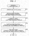
Fig. 2 is a flowchart for explaining an encoding operation to be performed by theencoding apparatus 10 ofFig. 1 . This encoding operation is started when an audio PCM signal is input to theencoding apparatus 10, for example. - In step S11 of
Fig. 2 , theMDCT unit 11 performs a MDCT on a PCM signal that is an audio time-domain signal that is input to theencoding apparatus 10, and generates the spectrum SP that is a frequency domain signal. TheMDCT unit 11 supplies the generated spectrum SP to the quantizingunit 12. - In step S12, the quantizing
unit 12 extracts envelopes from the higher frequency spectrum SP-H that is the higher frequency components of the spectrum SP supplied from theMDCT unit 11, and from the lower frequency spectrum SP-L that is the lower frequency components of the spectrum SP. - In step S13, the quantizing
unit 12 normalizes the lower frequency spectrum SP-L, using the lower frequency envelope ENV-L. - In step S14, the quantizing
unit 12 performs quantization on the extracted higher frequency envelope ENV-H, lower frequency envelope ENV-L, and on the normalized lower frequency spectrum SP-L.The quantizing unit 12 supplies the quantized higher frequency envelope ENV-H, lower frequency envelope ENV-L, and the normalized lower frequency spectrum SP-L to themultiplexing unit 13. - In step S15, the
multiplexing unit 13 multiplexes the lower frequency envelope ENV-L, the lower frequency spectrum SP-L, and the higher frequency envelope ENV-H, which are supplied from the quantizingunit 12. Themultiplexing unit 13 outputs the resultant bit stream. This operation then comes to an end. -
Fig. 3 is a block diagram showing an example structure of a decoding apparatus that decodes bit streams encoded by theencoding apparatus 10 ofFig. 1 . - The
decoding apparatus 30 ofFig. 3 includes a dividingunit 31, an inverse quantizingunit 32, aninverse MDCT unit 33, and aband extending unit 34. - The dividing
unit 31, the inverse quantizingunit 32, and theinverse MDCT unit 33 of thedecoding apparatus 30 decodes only the lower frequency components of PCM signals, like a conventional transform decoding apparatus. - Specifically, the dividing
unit 31 obtains a bit stream encoded by theencoding apparatus 10, and divides the bit stream into the lower frequency envelope ENV-L, the lower frequency spectrum SP-L, and the higher frequency envelope ENV-H. The dividingunit 31 then supplies the lower frequency envelope ENV-L, the lower frequency spectrum SP-L, and the higher frequency envelope ENV-H to the inverse quantizingunit 32. - The inverse quantizing
unit 32 performs inverse quantization on the lower frequency envelope ENV-L, the lower frequency spectrum SP-L, and the higher frequency envelope ENV-H, which are supplied from the dividingunit 31. The inverse quantizingunit 32 then supplies the inversely-quantized lower frequency envelope ENV-L and lower frequency spectrum SP-L to theinverse MDCT unit 33, and supplies the higher frequency envelope ENV-H to theband extending unit 34. - Using the lower frequency envelope ENV-L supplied from the inverse quantizing
unit 32, theinverse MDCT unit 33 denormalizes the lower frequency spectrum SP-L. Theinverse MDCT unit 33 performs an inverse MDCT on the lower frequency spectrum SP-L, which is a denormalized frequency domain signal, and obtains a PCM signal that is a time domain signal. This PCM signal is a PCM signal not containing higher frequency components, and is a PCM signal of auditorily muffled sound. Theinverse MDCT unit 33 supplies the PCM signal to theband extending unit 34. - The
band extending unit 34 includes aband dividing filter 41, a higher frequencycomponent generating unit 42, and aband combining filter 43. Theband extending unit 34 extends the frequency band of the PCM signal that is obtained by theinverse MDCT unit 33 and does not contain higher frequency components. By doing so, theband extending unit 34 performs a band extending operation to improve the sound quality of the PCM signal. - Specifically, the
band dividing filter 41 of theband extending unit 34 divides the PCM signal supplied from theinverse MDCT unit 33 into higher frequency components and lower frequency components. Since this PCM signal does not contain higher frequency components, theband dividing filter 41 discards the higher frequency components of the divided PCM signal. Theband dividing filter 41 also supplies a lower frequency PCM signal BS-L, which is the lower frequency components of the divided PCM signal, to the higher frequencycomponent generating unit 42 and theband combining filter 43. - Using the lower frequency PCM signal BS-L supplied from the
band dividing filter 41 and the higher frequency envelope ENV-H supplied from the inverse quantizingunit 32, the higher frequencycomponent generating unit 42 generates a higher frequency PCM signal to be a pseudo higher frequency PCM signal BS-H. An example method of generating the pseudo higher frequency PCM signal BS-H is disclosed inPatent Document 1, which was filed by the applicant. The higher frequencycomponent generating unit 42 supplies the pseudo higher frequency PCM signal BS-H to theband combining filter 43. - The
band combining filter 43 combines the lower frequency PCM signal BS-L supplied from theband dividing filter 41 with the pseudo higher frequency PCM signal BS-H supplied from the higher frequencycomponent generating unit 42, and outputs an entire-band PCM signal as the results of the decoding. - The sound corresponding to the entire-band PCM signal that is output in the above described manner is less muffled than the sound corresponding to the PCM signal not containing higher frequency components, and is a beautiful and comfortable sound.
-
Fig. 4 is a diagram for explaining the signals that are output from theinverse MDCT unit 33 and theband combining filter 43. InFig. 4 , the abscissa axis indicates frequency, and the ordinate axis indicates signal level. This also applies toFigs. 7 ,10 , and12 through 16 , which will be described later. - The signal that is output from the
inverse MDCT unit 33 is the PCM signal of the lower frequency spectrum SP-L denormalized by using the lower frequency envelope ENV-L, as shown in A inFig. 4 . The signal that is output from theband combining filter 43 is a PCM signal that contains lower frequency components as the PCM signal of the lower frequency spectrum SP-L denormalized by using the lower frequency envelope ENV-L, and higher frequency components as the pseudo higher frequency PCM signal BS-H generated from the higher frequency envelope ENV-H and the lower frequency PCM signal BS-L, as shown in B inFig. 4 . -
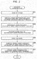
Fig. 5 is a flowchart for explaining a decoding operation to be performed by thedecoding apparatus 30 ofFig. 3 . This decoding operation is started when a bit stream encoded by theencoding apparatus 10 is input to thedecoding apparatus 30, for example. - In step S31 of
Fig. 5 , the dividingunit 31 divides the bit stream input to thedecoding apparatus 30 into the lower frequency envelope ENV-L, the lower frequency spectrum SP-L, and the higher frequency envelope ENV-H. The dividingunit 31 then supplies the lower frequency envelope ENV-L, the lower frequency spectrum SP-L, and the higher frequency envelope ENV-H to the inverse quantizingunit 32. - In step S32, the inverse quantizing
unit 32 performs inverse quantization on the lower frequency envelope ENV-L, the lower frequency spectrum SP-L, and the higher frequency envelope ENV-H, which are supplied from the dividingunit 31. The inverse quantizingunit 32 supplies the inversely-quantized lower frequency envelope ENV-L and lower frequency spectrum SP-L to theinverse MDCT unit 33. The inverse quantizingunit 32 supplies the higher frequency envelope ENV-H to theband extending unit 34. - In step S33, the
inverse MDCT unit 33 denormalizes the lower frequency spectrum SP-L, using the lower frequency envelope ENV-L supplied from theinverse quantizing unit 32. - In step S34, the
inverse MDCT unit 33 performs an inverse MDCT on the lower frequency spectrum SP-L, which is a denormalized frequency domain signal, and obtains a PCM signal that is a time domain signal. Theinverse MDCT unit 33 supplies the PCM signal to theband extending unit 34. - In step S35, the
band dividing filter 41 of theband extending unit 34 divides the PCM signal supplied from theinverse MDCT unit 33 into higher frequency components and lower frequency components. Theband dividing filter 41 discards the higher frequency components of the divided PCM signal, and supplies the lower frequency PCM signal BS-L, which is the lower frequency components of the divided PCM signal, to the higher frequencycomponent generating unit 42 and theband combining filter 43. - In step S36, the higher frequency
component generating unit 42 generates the pseudo higher frequency PCM signal BS-H, using the lower frequency PCM signal BS-L supplied from theband dividing filter 41 and the higher frequency envelope ENV-H supplied from theinverse quantizing unit 32. The higher frequencycomponent generating unit 42 supplies the pseudo higher frequency PCM signal BS-H to theband combining filter 43. - In step S37, the
band combining filter 43 combines the lower frequency PCM signal BS-L supplied from theband dividing filter 41 with the pseudo higher frequency PCM signal BS-H supplied from the higher frequencycomponent generating unit 42, to obtain the entire-band PCM signal. Theband combining filter 43 outputs the entire-band PCM signal, and the operation comes to an end. - The above described band extension technique has been already used in HE-AAC (High-Efficiency Advanced Audio Coding), which is an international standard, and in the stereo high-quality mode of LPEC (trade name).
- As described above, by the conventional band extension technique, the band extending operation is performed as the post processing for the decoding of the lower frequency spectrum SP-L. Accordingly, the degree of freedom of the pseudo higher frequency PCM signal BS-H can be made higher. That is, the pseudo higher frequency PCM signal BS-H can be generated not from the lower frequency spectrum SP-L, which is a frequency domain signal, but from the lower frequency PCM signal BS-L, which is a time domain signal.
- The processing block sizes in the encoding operation and the decoding operation, and the processing block size in the band extending operation are arbitrarily set, so as to optimize frequency analysis precision and time resolving precision.
- In a case where the pseudo higher frequency PCM signal is generated by the technique disclosed in
Patent Document 1, complicated procedures need to be carried out to generate a noise spectrum from the higher frequency envelope ENV-H, generate a tonic spectrum from the higher frequency envelope ENV-H and the lower frequency PCM signal BS-L, and compare the two spectrums. - The process of generating the noise spectrum and the tonic spectrum is the necessary process in increasing the matching accuracy between the lower frequency spectrum and the higher frequency spectrum to generate sound with high auditory quality, and is also performed in the decoding apparatuses disclosed in Patent Documents 2 and 3.
-
- Patent Document 1: Japanese Patent No.
3861770 - Patent Document 2: Japanese Patent No.
3646938 - Patent Document 3: Japanese Patent No.
3646939 - As described above, the conventional band extension technique has been studied, developed, and put into practice in such a manner that the band extending operation is performed as the post processing for the decoding of the lower frequency spectrum SP-L. Therefore, the entire-band PCM signal is output after the processing time required by the
band extending unit 34 has passed (time T1 in the example illustrated inFig. 3 ) from the end of the conventional decoding operation performed by the dividingunit 31, theinverse quantizing unit 32, and the inverse MDCT unit 33 (time T0 in the example illustrated inFig. 3 ). - This does not cause a serious problem, if the
decoding apparatus 30 is provided in a reproducing apparatus that reproduces only sound. In a case where thedecoding apparatus 30 is provided in a reproducing apparatus that reproduces video images in synchronization with sound, however, there is a difference in the output time of the entire-band PCM signal between a case where only the conventional decoding is performed and a case where the band extension is also performed. As a result, outputting video images in synchronization with sound becomes difficult. - To solve this problem, the timing to reproduce video images needs to be delayed. However, video image buffering requires a memory with a larger capacity than that for sound buffering, resulting in an increase in resources. The synchronizing timing between video images and sound may be delayed in advance. However, whether to perform only the conventional decoding and whether to perform the band extension as well as the conventional decoding depend on the reproducing apparatus to be used. Therefore, it is difficult to constantly designate the optimum synchronizing timing.
- The
decoding apparatus 30 needs to additionally include theband extending unit 34 for the band extension, resulting in more resources than in a decoding apparatus that does not perform the band extension. - In view of the above, decoding apparatuses that perform the band extension are expected to shorten the delay time caused by the band extension and restrain increases in resources.
- The present invention has been made in view of the above circumstances, and the object thereof is to shorten the delay time caused by the band extension at the time of decoding, and restrain increases in resources on the decoding side.
- A decoding apparatus according to a first aspect of the present invention includes: an obtaining unit configured to obtain, as encoding results, a lower frequency envelope of an audio signal, a lower frequency spectrum normalized by using the lower frequency envelope, a higher frequency envelope of the audio signal, and a degree of concentration of a higher frequency spectrum of the audio signal; a generating unit configured to generate a spectrum by using the normalized lower frequency spectrum and the higher frequency envelope in the encoding results obtained by the obtaining unit; a randomizing unit configured to randomize a phase of the spectrum, based on the degree of concentration, the spectrum being generated by the generating unit; and a combining unit configured to denormalize the lower frequency spectrum by using the lower frequency envelope in the encoding results obtained by the obtaining unit, and combine the spectrum randomized by the randomizing unit or the spectrum generated by the generating unit with the denormalized lower frequency spectrum, a result of the combination being used as a spectrum of an entire band.
- A decoding method and a program of the first aspect of the present invention correspond to the decoding apparatus of the first aspect of the present invention.
- In the first aspect of the present invention, the lower frequency envelope of an audio signal, the lower frequency spectrum normalized by using the lower frequency envelope, the higher frequency envelope of the audio signal, and the degree of concentration of the higher frequency spectrum of the audio signal are obtained as encoding results. A spectrum is generated by using the lower frequency spectrum and the higher frequency envelope in the obtained encoding results. Based on the degree of concentration, the phase of the spectrum is randomized. The lower frequency spectrum is denormalized by using the lower frequency envelope in the obtained encoding results. The randomized spectrum or the generated spectrum is combined with the denormalized lower frequency spectrum, and the combination result is used as the spectrum of the entire band.
- A decoding apparatus according to a second aspect of the present invention includes: an obtaining unit configured to obtain, as encoding results, a lower frequency envelope of an audio signal, a lower frequency spectrum normalized by using the lower frequency envelope, and a higher frequency envelope of the audio signal; a generating unit configured to generate a spectrum by using the normalized lower frequency spectrum and the higher frequency envelope in the encoding results obtained by the obtaining unit; a determining unit configured to determine a degree of concentration of the lower frequency spectrum, based on the normalized lower frequency spectrum in the encoding results obtained by the obtaining unit; a randomizing unit configured to randomize a phase of the spectrum, based on the degree of concentration determined by the determining unit, the spectrum being generated by the generating unit; and a combining unit configured to denormalize the lower frequency spectrum by using the lower frequency envelope in the encoding results obtained by the obtaining unit, and combine the spectrum randomized by the randomizing unit or the spectrum generated by the generating unit with the denormalized lower frequency spectrum, a result of the combination being used as a spectrum of an entire band.
- A decoding method and a program of the second aspect of the present invention correspond to the decoding apparatus of the second aspect of the present invention.
- In the second aspect of the present invention, the lower frequency envelope of an audio signal, the lower frequency spectrum normalized by using the lower frequency envelope, and the higher frequency envelope of the audio signal are obtained as encoding results. A spectrum is generated by using the normalized lower frequency spectrum and the higher frequency envelope in the obtained encoding results. Based on the normalized lower frequency spectrum in the obtained encoding results, the degree of concentration of the lower frequency spectrum is determined. Based on the determined degree of concentration, the phase of the generated spectrum is randomized. The lower frequency spectrum is denormalized by using the lower frequency envelope in the obtained encoding results. The randomized spectrum or the generated spectrum is combined with the denormalized lower frequency spectrum, and the combination result is used as the spectrum of the entire band.
- An encoding apparatus according to a third aspect of the present invention includes : a determining unit configured to determine a degree of concentration of a higher frequency spectrum of an audio signal, based on the higher frequency spectrum; an extracting unit configured to extract an envelope of a lower frequency spectrum and an envelope of the higher frequency spectrum from a spectrum of the audio signal; a normalizing unit configured to normalize the lower frequency spectrum by using the envelope of the lower frequency spectrum; and a multiplexing unit configured to obtain encoding results by multiplexing the degree of concentration determined by the determining unit, the envelope of the lower frequency spectrum and the envelope of the higher frequency spectrum extracted by the extracting unit, and the lower frequency spectrum normalized by the normalizing unit.
- An encoding method and a program of the third aspect of the present invention correspond to the encoding apparatus of the third aspect of the present invention.
- In the third aspect of the present invention, the degree of concentration of the higher frequency spectrum of an audio signal is determined, based on the higher frequency spectrum. The envelope of the lower frequency spectrum and the envelope of the higher frequency spectrum are extracted from the spectrum of the audio signal. The lower frequency spectrum is normalized by using the envelope of the lower frequency spectrum. The determined degree of concentration, the extracted envelope of the lower frequency spectrum, the extracted envelope of the higher frequency spectrum, and the normalized lower frequency spectrum are multiplexed, to obtain encoding results.
- The decoding apparatus of the first or second aspect and the encoding apparatus of the third aspect may be independent of each other, or may be internal blocks constituting an apparatus.
- According to the first and second aspects of the present invention, the delay time caused by the band extension at the time of decoding can be shortened, and increases in resources can be restrained.
- According to the third aspect of the present invention, encoding can be performed so that the delay time caused by the band extension at the time of decoding can be shortened, and increases in resources on the decoding side can be restrained.
-
-
Fig. 1 is a block diagram showing an example structure of an encoding apparatus. -
Fig. 2 is a flowchart for explaining an encoding operation to be performed by the encoding apparatus ofFig. 1 . -
Fig. 3 is a block diagram showing an example structure of a decoding apparatus. -
Fig. 4 is a diagram for explaining the signals that are output from the inverse MDCT unit and the band combining filter. -
Fig. 5 is a flowchart for explaining a decoding operation to be performed by the decoding apparatus ofFig. 3 . -
Fig. 6 is a block diagram showing an example structure of a first embodiment of an encoding apparatus to which the present invention is applied. -
Fig. 7 is a diagram for explaining the signals that are output from the MDCT unit and the quantizing unit ofFig. 6 . -
Fig. 8 is a flowchart for explaining an encoding operation to be performed by the encoding apparatus ofFig. 6 . -
Fig. 9 is a block diagram showing an example structure of a decoding apparatus that decodes bit streams encoded by the encoding apparatus ofFig. 6 . -
Fig. 10 is a diagram for explaining the signal that is output from the inverse MDCT unit ofFig. 9 . -
Fig. 11 is a diagram for explaining the difference in decoding results between a case where phase randomization is performed and a case where phase randomization is not performed. -
Fig. 12 is a diagram for explaining the characteristics of the higher frequency spectrum SP-H. -
Fig. 13 is a diagram for explaining the characteristics of the higher frequency spectrum SP-H. -
Fig. 14 is a diagram for explaining the characteristics of the higher frequency spectrum SP-H. -
Fig. 15 is a diagram for explaining the characteristics of the higher frequency spectrum SP-H. -
Fig. 16 is a diagram for explaining the characteristics of the higher frequency spectrum SP-H. -
Fig. 17 is a flowchart for explaining a decoding operation to be performed by the decoding apparatus ofFig. 9 . -
Fig. 18 is a block diagram showing an example structure of a second embodiment of a decoding apparatus to which the present invention is applied. -
Fig. 19 is a flowchart for explaining a decoding operation to be performed by the decoding apparatus ofFig. 18 . -
Fig. 20 is a diagram showing an example structure of a computer. -
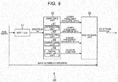
Fig. 6 is a block diagram showing an example structure of a first embodiment of an encoding apparatus to which the present invention is applied. - In the structure shown in
Fig. 6 , the same components as those shown inFig. 1 are denoted by the same reference numerals as those shown inFig. 1 , and the same explanation will not be repeated. - The structure of the
encoding apparatus 50 ofFig. 6 differs from the structure ofFig. 1 in that the quantizingunit 12 and the multiplexingunit 13 are replaced with a quantizingunit 51 and amultiplexing unit 52. Theencoding apparatus 10 generates a bit stream by multiplexing a random flag RND (described later in detail) as well as a lower frequency envelope ENV-L, a lower frequency spectrum SP-L, and a higher frequency envelope ENV-H. - Specifically, the quantizing
unit 51 of theencoding apparatus 50 includes a determiningunit 61, an extractingunit 62, a normalizingunit 63, and apartial quantizing unit 64. - Based on the higher frequency spectrum SP-H of a spectrum SP supplied from a
MDCT unit 11, the determiningunit 61 determines the degree of concentration D of the higher frequency spectrum SP-H according to the following equation (1):
- In the equation (1), max(SP-H) represents the maximum value of the higher frequency spectrum SP-H, and ave(SP-H) represents the average value of the higher frequency spectrum SP-H.
- According to the equation (1), in a case where the tone characteristics of the higher frequency components of the sound to be encoded are prominent and the distribution of the higher frequency spectrum SP-H has a high degree of bias, the degree of concentration D is high. In a case where the noise characteristics of the higher frequency components of the sound to be encoded are prominent and the distribution of the higher frequency spectrum SP-H is uniform, the degree of concentration D is low.
- The determining
unit 61 determines the random flag RND, based on the degree of concentration D. The random flag RND is a flag that indicates whether to randomize the phase of the spectrum to approximate the higher frequency spectrum SP-H generated from the lower frequency spectrum SP-L and the higher frequency envelope ENV-H in a band extending operation in a later described decoding apparatus. - In a case where the degree of concentration D is higher than a threshold value that is set in the
encoding apparatus 50 in advance, or where the tone characteristics of the higher frequency spectrum SP-H are prominent, for example, the random flag RND is set to 0, which indicates that randomization is not to be performed. In a case where the degree of concentration D is equal to or lower than the predetermined threshold value, or where the noise characteristics of the higher frequency spectrum SP-H are prominent, the random flag RND is set to 1, which indicates randomization is to be performed. The determiningunit 61 supplies the determined random flag RND to themultiplexing unit 52. - Like the quantizing
unit 12 ofFig. 1 , the extractingunit 62 extracts envelopes from the higher frequency spectrum SP-H and the lower frequency spectrum SP-L of the spectrum SP supplied from theMDCT unit 11. - Like the quantizing
unit 12, the normalizingunit 63 normalizes the lower frequency spectrum SP-L, using the lower frequency envelope ENV-L. - The
partial quantizing unit 64 performs quantization on the normalized lower frequency spectrum SP-L, and supplies the resultant lower frequency spectrum SP-L to themultiplexing unit 52. Like the quantizingunit 12, thepartial quantizing unit 64 also quantizes the extracted higher frequency envelope ENV-H and lower frequency envelope ENV-L. Like the quantizingunit 12, thepartial quantizing unit 64 supplies the quantized higher frequency envelope ENV-H and lower frequency envelope ENV-L to themultiplexing unit 52. - The multiplexing
unit 52 multiplexes the random flag RND supplied from the determiningunit 61 of the quantizingunit 51, as well as the lower frequency envelope ENV-L, the lower frequency spectrum SP-L, and the higher frequency envelope ENV-H, which are supplied from thepartial quantizing unit 64. The multiplexingunit 52 outputs the resultant bit stream. This bit stream is recorded on a recording medium (not shown), or is transferred to a decoding apparatus. -
Fig. 7 is a diagram for explaining the signals that are output from theMDCT unit 11 and the quantizingunit 51 of theencoding apparatus 50 ofFig. 6 . - As shown in A in
Fig. 7 , the spectrum SP that is output from theMDCT unit 11 is a spectrum of the entire band. On the other hand, the signal that is output from the quantizingunit 51 and excludes the random flag RND includes the lower frequency spectrum SP-L, the lower frequency envelope ENV-L, and the higher frequency envelope ENV-H, as shown in B inFig. 7 . -
Fig. 8 is a flowchart for explaining an encoding operation to be performed by theencoding apparatus 50 ofFig. 6 . This encoding operation is started when an audio PCM signal is input to theencoding apparatus 50, for example. - In step S51 of
Fig. 8 , theMDCT unit 11 performs a MDCT on the PCM signal that is an audio time-domain signal input to theencoding apparatus 50, to generate the spectrum SP, which is a frequency domain signal, as in step S11 ofFig. 2 . TheMDCT unit 11 supplies the generated spectrum SP to the quantizingunit 51. - In step S52, based on the higher frequency spectrum SP-H of the spectrum SP supplied from the
MDCT unit 11, the determiningunit 61 of the quantizingunit 51 determines the degree of concentration D of the higher frequency spectrum SP-H according to the above described equation (1). - In step S53, the determining
unit 61 determines the random flag RND, based on the degree of concentration D. The determiningunit 61 supplies the determined random flag RND to themultiplexing unit 52, and the operation moves on to step S54. - The procedures of steps S54 through S56 are the same as the procedures of steps S12 through S14 of
Fig. 2 , and therefore, explanation of them is not repeated herein. - After the procedure of step S56, the multiplexing
unit 52, in step S57, multiplexes the random flag RND, the lower frequency envelope ENV-L, the lower frequency spectrum SP-L, and the higher frequency envelope ENV-H, which are supplied from the quantizingunit 51. The multiplexingunit 52 outputs the resultant bit stream. The operation then comes to an end. -
Fig. 9 is a block diagram showing an example structure of the decoding apparatus that decodes bit streams encoded by theencoding apparatus 50 ofFig. 6 . - The
decoding apparatus 70 ofFig. 9 includes a dividingunit 71, aninverse quantizing unit 72, a higher frequencycomponent generating unit 73, aphase randomizing unit 74, and aninverse MDCT unit 75. Thedecoding apparatus 70 performs a band extending operation at the same time as decoding of the lower frequency spectrum SPL. - Specifically, the dividing unit 71 (an obtaining unit) obtains a bit stream encoded by the
encoding apparatus 50 ofFig. 6 . The dividingunit 71 divides the bit stream into the random flag RND, the lower frequency envelope ENV-L, the lower frequency spectrum SP-L, and the higher frequency envelope ENV-H, which are then supplied to theinverse quantizing unit 72. - Like the
inverse quantizing unit 32 ofFig. 3 , theinverse quantizing unit 72 performs inverse quantization on the lower frequency envelope ENV-L, the lower frequency spectrum SP-L, and the higher frequency envelope ENV-H, which are supplied from the dividingunit 71. - The
inverse quantizing unit 72 supplies the inversely-quantized lower frequency envelope ENV-L to theinverse MDCT unit 75, and supplies the lower frequency spectrum SP-L to theinverse MDCT unit 75 and the higher frequencycomponent generating unit 73. Theinverse quantizing unit 72 also supplies the higher frequency envelope ENV-H to the higher frequencycomponent generating unit 73, and supplies the random flag RND to thephase randomizing unit 74. - Using the lower frequency spectrum SP-L and the higher frequency envelope ENV-H, which are supplied from the
inverse quantizing unit 72, the higher frequencycomponent generating unit 73 generates a higher frequency spectrum to be a pseudo higher frequency spectrum. Specifically, the higher frequencycomponent generating unit 73 duplicates the lower frequency spectrum SP-L, and deforms the duplicated spectrum by using the higher frequency envelope ENV-H, to form the pseudo higher frequency spectrum. - To generate this pseudo higher frequency spectrum, the technique disclosed in
Patent Document 1, which was filed by the applicant, may be used, or some other technique may also be used. The higher frequencycomponent generating unit 73 supplies the generated pseudo higher frequency spectrum to thephase randomizing unit 74. - Based on the random flag RND supplied from the
inverse quantizing unit 72, thephase randomizing unit 74 randomizes the phase of the pseudo higher frequency spectrum supplied from the higher frequencycomponent generating unit 73. - Specifically, in a case where the random flag RND is 1, which indicates that randomization is to be performed, the
phase randomizing unit 74 randomizes the sign (+ or -) of the pseudo higher frequency spectrum, according to the following equation (2):
- In the equation (2), SP-H represents the higher frequency spectrum, and i represents the spectrum number.
- According to the equation (2), the higher frequency spectrum SP-H is multiplied by "-1" the number of times indicated by the lowest 1 bit of the return value of the random function rand(), so that -1 or 1 is randomly assigned to the sign of the higher frequency spectrum SP-H.
- In a case where the random flag RND is 0, which indicates that randomization is not to be performed, the
phase randomizing unit 74 does not randomize the phase of the pseudo higher frequency spectrum. - The
phase randomizing unit 74 supplies the pseudo higher frequency spectrum having its phase randomized or the pseudo higher frequency spectrum not having its phase randomized to theinverse MDCT unit 75. - The inverse MDCT unit 75 (a combining unit) denormalizes the lower frequency spectrum SP-L, using the lower frequency envelope ENV-L supplied from the
inverse quantizing unit 72. Theinverse MDCT unit 75 combines the denormalized lower frequency spectrum SP-L with the pseudo higher frequency spectrum supplied from thephase randomizing unit 74. Theinverse MDCT unit 75 performs an inverse MDCT on the entire-band spectrum that is a frequency domain signal obtained as a result of the combination. By doing so, theinverse MDCT unit 75 obtains an entire-band PCM signal that is a time domain signal. Theinverse MDCT unit 75 outputs the entire-band PCM signal as the results of the decoding. - As described above, the
decoding apparatus 70 generates the pseudo higher frequency spectrum at the same time as decoding of the lower frequency spectrum SP-L. Accordingly, the time required for decoding in thedecoding apparatus 70 is substantially the same as the time required for decoding in a conventional decoding apparatus that performs only decoding. That is, thedecoding apparatus 70 ofFig. 9 can output results of decoding after time T0 has passed from the time of the bit stream input. In other words, any delay is not caused by a band extension in thedecoding apparatus 70. -
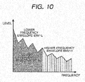
Fig. 10 is a diagram for explaining the signal that is output from theinverse MDCT unit 75 of thedecoding apparatus 70 ofFig. 9 . - The signal that is output from the
inverse MDCT unit 75 is a PCM signal obtained after a frequency transform is performed on the result of the combination of the lower frequency spectrum SP-L normalized by using the lower frequency envelope ENV-L as shown inFig. 10 , and the pseudo higher frequency spectrum generated from the higher frequency envelope ENV-H and the lower frequency spectrum SP-L as shown inFig. 10 . -
Figs. 11 through 16 are diagrams for explaining the effects of phase randomization performed by thephase randomizing unit 74 ofFig. 9 . -
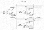
Fig. 11 is a diagram for explaining the difference in decoding results between a case where phase randomization is performed and a case where phase randomization is not performed. - As shown in
Fig. 11 , theencoding apparatus 50 ofFig. 6 encodes a PCM signal in each section called a frame having a constant length. Those frames normally overlap one another by 50%. Specifically, the (J-1)th frame and the Jth frame overlap each other by half a frame, as shown inFig. 11 . -
Fig. 11 illustrates a case where a spectrum with distinctive tone characteristics is encoded, as shown on the left side ofFig. 11 . - In this case, where the phase of the spectrum is not randomized at the time of decoding of the spectrums of the (J-1)th and Jth frames as shown in the upper right portion of
Fig. 11 , the phase of the spectrum of the overlapping period between the (J-1)th frame and the Jth frame is accurately restored by a combination of the signs and the spectrums of the (J-1)th and Jth frames. Accordingly, the restored spectrum of the overlapping period is a spectrum with distinctive tone characteristics. - Where the phase of the spectrum is randomized at the time of decoding of the spectrums of the (J-1) th and Jth frames as shown in the lower right portion, on the other hand, the signs of the spectrums of the (J-1)th and Jth frames are not always the same. Therefore, the phase of the spectrum of the overlapping period is not accurately restored. As a result, the restored signal of the overlapping period in the
decoding apparatus 70 is a spectrum having poorer tone characteristics than the tone characteristics of the spectrum prior to the encoding. - As the tone characteristics of the spectrum become poorer, the energy originally concentrating on the specific spectrum leaks into the surrounding spectrums. Therefore, the peaks (tops) of the spectrum are more restrained compared with the original spectrum, and the energy of the bottoms of the spectrum is boosted by the energy leaking into the surroundings. As a result, the spectrum acquires noise characteristics.
- As described above, where phase randomization is performed at the time of decoding, the spectrum having tone characteristics prior to encoding is transformed into a spectrum having noise characteristics.
-
Figs. 12 through 16 are diagrams for explaining the characteristics of the higher frequency spectrum SP-H. - As shown in A in
Fig. 12 , where the tone characteristics of the lower frequency spectrum SP-L are distinctive, the tone characteristics of the higher frequency spectrum SP-H are often distinctive too. This can be deduced from the fact that instruments such as wind instruments and string instruments emit sound waves that are a combination of basic frequency and harmonic components that are integral multiples of the basic frequency. - In a case where band extension encoding is performed on the spectrum formed with the lower frequency spectrum SP-L and the higher frequency spectrum SP-H, which have distinctive tone characteristics, a pseudo higher frequency spectrum that is generated by simply replicating the lower frequency spectrum SP-L at the time of band extension decoding is a spectrum with distinctive tone characteristics as shown in B in
Fig. 12 . Accordingly, the sound corresponding to the results of decoding is hardly disagreeable to the ear. - Therefore, in a case where the degree of concentration D is higher than the predetermined threshold value, or where the higher frequency components of the sound to be encoded have tone characteristics, the
encoding apparatus 50 ofFig. 6 sets the random flag RND to 0. Therefore, the phase of the pseudo higher frequency spectrum is not randomized in thedecoding apparatus 70. Accordingly, the sound corresponding to the results of decoding is hardly disagreeable to the ear. - In a case where the lower frequency spectrum SP-L has distinctive noise characteristics, the noise characteristics become more distinctive at higher frequencies, as shown in A in
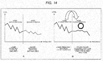
Fig. 13 and A inFig. 14 . This can be deduced from the fact that vibrations of higher frequencies propagate in instruments such as cymbals and maracas that emits hit sound and impact sound with distinctive noise characteristic or without tone characteristics, and higher frequency sound has more distinctive noise characteristics, with the amplitudes and phases of the respective vibration factors being intricately intertwined. - In a case where band extension encoding is performed on a spectrum formed with the lower frequency spectrum SP-L and the higher frequency spectrum SP-H having distinctive noise characteristics as described above, a pseudo higher frequency spectrum generated by using the lower frequency spectrum SP-L at the time of band extension decoding is a spectrum with distinctive noise characteristics as shown in B in
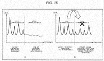
Fig. 13 . Therefore, where phase randomization is not performed on the pseudo higher frequency spectrum as shown in B inFig. 13 or where phase randomization is performed as shown in B inFig. 14 , the noise characteristics of the pseudo higher frequency spectrum are distinctive, and the sound corresponding to the results of decoding is hardly disagreeable to the ear. - However, the lower frequency components of sound of instruments with distinctive noise characteristics such as cymbals or maracas might contain tonic vibrational components. Also, the frequencies of sound of instruments such as cymbals and maracas are mainly high frequencies, and there is a possibility that the lower frequency components also contain sound with distinctive tone characteristics. Therefore, even in a case where the noise characteristics of the higher frequency spectrum SP-H are distinctive, the tone characteristics of the lower frequency spectrum SP-L might be distinctive as shown in A in
Fig. 15 and A inFig. 16 . - In a case where band extension encoding is performed on a spectrum formed with the lower frequency spectrum SP-L with distinctive tone characteristics and the higher frequency spectrum SP-H with distinctive noise characteristics as described above, a pseudo higher frequency spectrum generated by using the lower frequency spectrum SP-L at the time of band extension decoding might contain tonic components, as shown in B in
Fig. 15 . Therefore, if the phase of the pseudo higher frequency spectrum is not randomized as shown in B ofFig. 15 , the higher frequency sound corresponding to the results of decoding does not have the original noise characteristics, but have tone characteristics like the lower frequency sound, resulting in sound that is disagreeable to the ear. - In a case where the phase of the pseudo higher frequency spectrum is randomized, on the other hand, the pseudo higher frequency spectrum after the randomization have noise characteristics as shown in B in
Fig. 16 , even if the original pseudo higher frequency spectrum contains tonic components. Accordingly, the sound corresponding to the results of decoding is hardly disagreeable to the ear. - In a case where the higher frequency spectrum SP-H has noise characteristics, randomization may be or may not be performed, if the lower frequency spectrum SP-L also has noise characteristics. In that case, however, randomization needs to be performed, if the lower frequency spectrum SP-L has tone characteristics. Therefore, in a case where the higher frequency spectrum SP-H has noise characteristics, randomization is constantly performed, so that decoding results that are hardly disagreeable to the ear can be achieved based on the degree of concentration D.
- In view of this, in a case where the degree of concentration D is equal to or lower than the predetermined threshold value, or where the higher frequency components of the sound to be encoded have noise characteristics, the
encoding apparatus 50 ofFig. 6 sets the random flag RND to 1. As a result, the phase of the pseudo higher frequency spectrum is randomized in thedecoding apparatus 70. Accordingly, the sound corresponding to the results of decoding is hardly disagreeable to the ear. - Since there exists almost no sound that has distinctive noise characteristics at lower frequencies and distinctive tone characteristics at higher frequencies in nature, a spectrum formed with the lower frequency spectrum SP-L with distinctive noise characteristics and the higher frequency spectrum SP-H with distinctive tone characteristics is not discussed herein.
-
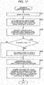
Fig. 17 is a flowchart for explaining a decoding operation to be performed by thedecoding apparatus 70 ofFig. 9 . This decoding operation is started when a bit stream encoded by theencoding apparatus 50 is input to thedecoding apparatus 70, for example. - In step S71 of
Fig. 17 , the dividingunit 71 obtains the bit stream encoded by theencoding apparatus 50, and divides the bit stream into the random flag RND, the lower frequency envelope ENV-L, the lower frequency spectrum SP-L, and the higher frequency envelope ENV-H.The dividing unit 71 supplies the random flag RND, the lower frequency envelope ENV-L, the lower frequency spectrum SP-L, and the higher frequency envelope ENV-H to theinverse quantizing unit 72. - In step S72, the
inverse quantizing unit 72 performs inverse quantization on the lower frequency envelope ENV-L, the lower frequency spectrum SP-L, and the higher frequency envelope ENV-H, which are supplied from the dividingunit 71. Theinverse quantizing unit 72 supplies the inversely-quantized lower frequency envelope ENV-L to theinverse MDCT unit 75, and supplies the lower frequency spectrum SP-L to theinverse MDCT unit 75 and the higher frequencycomponent generating unit 73. Also, theinverse quantizing unit 72 supplies the higher frequency envelope ENV-H to the higher frequencycomponent generating unit 73, and supplies the random flag RND to thephase randomizing unit 74. - In step S73, the higher frequency
component generating unit 73 generates a pseudo higher frequency spectrum by using the lower frequency spectrum SP-L and the higher frequency envelope ENV-H, which are supplied from theinverse quantizing unit 72. The higher frequencycomponent generating unit 73 supplies the generated pseudo higher frequency spectrum to thephase randomizing unit 74. - In step S74, the
phase randomizing unit 74 determines whether the random flag RND supplied from theinverse quantizing unit 72 is 1. If the random flag RND is determined to be 1 in step S74, thephase randomizing unit 74, in step S75, randomizes the phase of the pseudo higher frequency spectrum supplied from the higher frequencycomponent generating unit 73, according to the above described equation (2). Thephase randomizing unit 74 then supplies the pseudo higher frequency spectrum having its phase randomized to theinverse MDCT unit 75, and the operation moves on to step S76. - If the random flag RND is determined not to be 1 or is determined to be 0 in step S74, the
phase randomizing unit 74 does not randomize the phase of the pseudo higher frequency spectrum, and supplies the pseudo higher frequency spectrum as it is to theinverse MDCT unit 75. The operation then moves on to step S76. - In step S76, the
inverse MDCT unit 75 denormalizes the lower frequency spectrum SP-L by using the lower frequency envelope ENV-L supplied from theinverse quantizing unit 32. - In step S77, the
inverse MDCT unit 75 combines the denormalized lower frequency spectrum SP-L with the pseudo higher frequency spectrum supplied from thephase randomizing unit 74, and performs an inverse MDCT on the resultant entire-band spectrum. By doing so, theinverse MDCT unit 75 obtains an entire-band PCM signal. Theinverse MDCT unit 75 outputs the entire-band PCM signal as decoding results, and the operation comes to an end. - As described above, the
decoding apparatus 70 generates the pseudo higher frequency spectrum by using the lower frequency spectrum SP-L prior to the inverse MDCT, and randomizes the pseudo higher frequency spectrum in accordance with the random flag RND determined based on the degree of concentration of the higher frequency spectrum SP-H. By doing so, thedecoding apparatus 70 restores the higher frequency components of the spectrum of the sound to be encoded. - By using the lower frequency spectrum SP-L in the above manner, a spectrum that is relatively similar to the higher frequency spectrum SP-H can be restored as the higher frequency components of the spectrum of sound to be encoded. Accordingly, as the higher frequency components of the spectrum of sound to be encoded are restored by using the lower frequency spectrum SP-L, a decoding operation and a band extending operation can be simultaneously performed on the lower frequency spectrum SP-L, and the delay time caused by the band extension can be shortened. As a result, the entire-band PCM signal of sound that is not muffled and is beautiful and agreeable to the ear is output as the results of decoding after substantially the same period of time has passed as in a decoding apparatus not performing the band extension operation.
- Also, the
decoding apparatus 70 randomizes the phase of the pseudo higher frequency spectrum generated by using the lower frequency spectrum SP-L, to generate a pseudo higher frequency spectrum with noise characteristics. Accordingly, thedecoding apparatus 70 can generate a pseudo higher frequency spectrum that is more similar to the higher frequency spectrum SP-H than in a case where a random spectrum is simply generated as a pseudo higher frequency spectrum. - Further, the
decoding apparatus 70 generates the lower frequency components and the higher frequency components of a spectrum prior to the inverse MDCT. Therefore, thedecoding apparatus 70 does not need to include theband dividing filter 41 and theband combining filter 43 for band extending operations, like thedecoding apparatus 30 ofFig. 3 . Accordingly, the processing for band extending operations, and the resources such as the circuit size and the code size can be reduced, compared with those in thedecoding apparatus 30 ofFig. 3 . -
Fig. 18 is a block diagram showing an example structure of a second embodiment of a decoding apparatus to which the present invention is applied. - Of the components shown in
Fig. 18 , the same components as those shown inFigs. 3 and9 are denoted by the same reference numerals used inFigs. 3 and9 , and the same explanation will not be repeated. - The structure of the
decoding apparatus 100 ofFig. 18 differs from the structure of thedecoding apparatus 70 ofFig. 9 in that the dividingunit 71 and theinverse quantizing unit 72 are replaced with a dividingunit 31 and aninverse quantizing unit 32, and a determiningunit 101 is added. Thedecoding apparatus 100 determines a random flag RND, based on a lower frequency spectrum SP-L included in a bit stream encoded by theencoding apparatus 10 ofFig. 1 . - Specifically, based on the lower frequency spectrum SP-L inversely-quantized by the
inverse quantizing unit 32, the determiningunit 101 determines the degree of concentration D' of the lower frequency spectrum SP-L according to the following equation (3), for example:
- In the equation (3), max(SP-L) represents the maximum value of the lower frequency spectrum SP-L, and ave(SP-L) represents the average value of the lower frequency spectrum SP-L.
- According to the equation (3), in a case where the tone characteristics of the lower frequency components of the sound to be encoded are distinctive and the distribution of the lower frequency spectrum SP-L has a high degree of bias, the degree of concentration D' is high. In a case where the noise characteristics of the lower frequency components of the sound to be encoded are distinctive and the distribution of the lower frequency spectrum SP-L is uniform, the degree of concentration D' is low.
- The determining
unit 101 determines the random flag RND, based on the degree of concentration D'. Specifically, in a case where the degree of concentration D is higher than a threshold value that is set in thedecoding apparatus 100 in advance, or where the tone characteristics of the lower frequency spectrum SP-L are distinctive, the determiningunit 101 determines the random flag RND to be 0. In a case where the degree of concentration D' is equal to or lower than the predetermined threshold value, or where the noise characteristics of the lower frequency spectrum SP-L are distinctive, on the other hand, the determiningunit 101 determines the random flag RND to be 1. The determiningunit 101 supplies the determined random flag RND to thephase randomizing unit 74. Accordingly, where the tone characteristics of the lower frequency spectrum SP-L are distinctive, the phase of a pseudo higher frequency spectrum is not randomized. Where the noise characteristics of the lower frequency spectrum SP-L are distinctive, the phase of the pseudo higher frequency spectrum is randomized. As a result, the sound corresponding to the results of decoding has a sufficiently high auditory quality. -
Fig. 19 is a flowchart for explaining a decoding operation to be performed by thedecoding apparatus 100 ofFig. 18 . This decoding operation is started when a bit stream encoded by theencoding apparatus 10 ofFig. 1 is input to thedecoding apparatus 100, for example. - In step S91 of
Fig. 19 , the dividingunit 31 divides the bit stream encoded by theencoding apparatus 10 into a lower frequency envelope ENV-L, the lower frequency spectrum SP-L, and a higher frequency envelope ENV-H, which are then supplied to theinverse quantizing unit 32. - The procedures of steps S92 and S93 are the same as the procedures of steps S72 and S73 of
Fig. 17 , and therefore, explanation of them is not repeated herein. - After the procedure of step S93, the determining
unit 101, in step S94, determines the degree of concentration D' of the lower frequency spectrum SP-L according to the above described equation (3), based on the lower frequency spectrum SP-L inversely-quantized by theinverse quantizing unit 32. - In step S95, the determining
unit 101 determines the random flag RND, based on the degree of concentration D'. The determiningunit 101 supplies the random flag RND to thephase randomizing unit 74, and the operation moves on to step S96. - The procedures of steps S96 through S99 are the same as the procedures of steps S74 through S77 of
Fig. 17 , and therefore, explanation of them is not repeated herein. - The above described series of encoding procedures and decoding procedures can be carried out by hardware or software. In a case where the series of encoding procedures and decoding procedures are carried out by software, the programs as the software are installed in a general-purpose computer or the like.
-
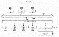
Fig. 20 shows an example structure of an embodiment of the computer in which the programs for carrying out the above described series of procedures are installed. - The programs can be recorded beforehand in a
storage unit 208 or a ROM (Read Only Memory) 202 that are provided as recording media in the computer. - Alternatively, the programs may be stored (recorded) in a
removable medium 211. This removable medium 211 can be provided as so-called package software. Here, theremovable medium 211 may be a flexible disc, a CD-ROM (Compact Disc Read Only Memory), a MO (Magneto Optical) disc, a DVD (Digital Versatile Disc), a magnetic disc, a semiconductor memory, or the like, for example. - The programs are installed in the computer from the above described removable medium 211 via a
drive 210. Alternatively, the programs may be downloaded into the computer via a communication network or a broadcast network, and be installed in theinternal storage unit 208. That is, the programs can be transferred wirelessly from a download site to the computer via an artificial satellite for digital satellite broadcasting, or can be transferred online to the computer via a network such as a LAN (Local Area Network) or the Internet, for example. - The computer includes a CPU (Central Processing Unit) 201, and an input/
output interface 205 is connected to theCPU 201 via abus 204. - When an instruction is input by a user operating an
input unit 206 via the input/output interface 205, theCPU 201 executes a program stored in theROM 202, in accordance with the instruction. Alternatively, theCPU 201 loads the program from thestorage unit 208 into a RAM (Random Access Memory) 203, and then executes the program. - With this arrangement, the
CPU 201 performs operations according to the above described flowcharts or performs operations with the structures shown in the above described block diagrams. Via the input/output interface 205, theCPU 201 outputs the results of the operations from anoutput unit 207, or transmits the results from acommunication unit 209, or records the results into thestorage unit 208, for example, where necessary. - The
input unit 206 is a keyboard, a mouse, a microphone, or the like. Theoutput unit 207 is a LCD (Liquid Crystal Display), a speaker, or the like. - In this specification, procedures to be carried out by the computer in accordance with the programs are not necessarily carried out in chronological order by following the sequences shown in the flowcharts. That is, the procedures to be carried out by the computer in accordance with the programs include procedures to be carried out in parallel or independently of one another (such as parallel processing or processing by objects, for example).
- The programs may be executed by a computer (or a processor), or may be executed by two or more computers in a distributed manner. Further, the programs may be transferred to a remote computer, and be executed by the remote computer.
- Embodiments of the present invention are not limited to the above described embodiments, and various modifications may be made to them without departing from the scope of the invention.
- Further embodiments of the invention are defined in the following numbered paragraphs:
- 1. A decoding apparatus comprising:
- an obtaining unit configured to obtain, as encoding results, a lower frequency envelope of an audio signal, a lower frequency spectrum normalized by using the lower frequency envelope, a higher frequency envelope of the audio signal, and a degree of concentration of a higher frequency spectrum of the audio signal;
- a generating unit configured to generate a spectrum by using the normalized lower frequency spectrum and the higher frequency envelope in the encoding results obtained by the obtaining unit;
- a randomizing unit configured to randomize a phase of the spectrum, based on the degree of concentration, the spectrum being generated by the generating unit; and
- a combining unit configured to denormalize the lower frequency spectrum by using the lower frequency envelope in the encoding results obtained by the obtaining unit, and combine the spectrum randomized by the randomizing unit or the spectrum generated by the generating unit with the denormalized lower frequency spectrum, a result of the combination being used as a spectrum of an entire band.
- 2. The decoding apparatus according to
paragraph 1, wherein
when the degree of concentration is higher than a predetermined threshold value, the randomizing unit does not randomize the phase of the spectrum generated by the generating unit, and
when the degree of concentration is equal to or lower than the predetermined threshold value, the randomizing unit randomizes the phase of the spectrum generated by the generating unit. - 3. The decoding apparatus according to
paragraph 1, wherein
the obtaining unit obtains a random flag, the random flag being information indicating whether the randomizing unit is to perform randomization, the random flag being determined based on the lower frequency envelope, the lower frequency spectrum, the higher frequency envelope, and the degree of concentration,
when the random flag is information indicating that the randomization is to be performed, the randomizing unit randomizes the phase of the spectrum and supplies the randomized spectrum to the combining unit, and
when the random flag is information indicating that the randomization is not to be performed, the randomizing unit does not randomize the phase of the spectrum and supplies the spectrum to the combining unit. - 4. A decoding method implemented in a decoding apparatus,
the decoding method comprising:- an obtaining step of obtaining, as encoding results, a lower frequency envelope of an audio signal, a lower frequency spectrum normalized by using the lower frequency envelope, a higher frequency envelope of the audio signal, and a degree of concentration of a higher frequency spectrum of the audio signal;
- a generating step of generating a spectrum by using the normalized lower frequency spectrum and the higher frequency envelope in the encoding results obtained in the obtaining step;
- a randomizing step of randomizing a phase of the spectrum, based on the degree of concentration, the spectrum being generated in the generating step; and
- a combining step of denormalizing the lower frequency spectrum by using the lower frequency envelope in the encoding results obtained in the obtaining step, and combining the spectrum randomized in the randomizing step or the spectrum generated in the generating step with the denormalized lower frequency spectrum, a result of the combination being used as a spectrum of an entire band.
- 5. A program for causing a computer to perform an operation comprising:
- an obtaining step of obtaining, as encoding results, a lower frequency envelope of an audio signal, a lower frequency spectrum normalized by using the lower frequency envelope, a higher frequency envelope of the audio signal, and a degree of concentration of a higher frequency spectrum of the audio signal;
- a generating step of generating a spectrum by using the normalized lower frequency spectrum and the higher frequency envelope in the encoding results obtained in the obtaining step;
- a randomizing step of randomizing a phase of the spectrum, based on the degree of concentration, the spectrum being generated in the generating step; and
- a combining step of denormalizing the lower frequency spectrum by using the lower frequency envelope in the encoding results obtained in the obtaining step, and combining the spectrum randomized in the randomizing step or the spectrum generated in the generating step with the denormalized lower frequency spectrum, a result of the combination being used as a spectrum of an entire band.
- 6. A decoding apparatus comprising:
- an obtaining unit configured to obtain, as encoding results, a lower frequency envelope of an audio signal, a lower frequency spectrum normalized by using the lower frequency envelope, and a higher frequency envelope of the audio signal;
- a generating unit configured to generate a spectrum by using the normalized lower frequency spectrum and the higher frequency envelope in the encoding results obtained by the obtaining unit;
- a determining unit configured to determine a degree of concentration of the lower frequency spectrum, based on the normalized lower frequency spectrum in the encoding results obtained by the obtaining unit;
- a randomizing unit configured to randomize a phase of the spectrum, based on the degree of concentration determined by the determining unit, the spectrum being generated by the generating unit; and
- a combining unit configured to denormalize the lower frequency spectrum by using the lower frequency envelope in the encoding results obtained by the obtaining unit, and combine the spectrum randomized by the randomizing unit or the spectrum generated by the generating unit with the denormalized lower frequency spectrum, a result of the combination being used as a spectrum of an entire band.
- 7. The decoding apparatus according to paragraph 6, wherein
when the degree of concentration is higher than a predetermined threshold value, the randomizing unit does not randomize the phase of the spectrum generated by the generating unit, and
when the degree of concentration is equal to or lower than the predetermined threshold value, the randomizing unit randomizes the phase of the spectrum generated by the generating unit. - 8. The decoding apparatus according to paragraph 6, wherein
when the degree of concentration of the lower frequency spectrum is higher than a predetermined threshold value, the determining unit determines a random flag to be information indicating that the randomizing unit is not to perform randomization, the random flag being information indicating whether the randomizing unit is to perform the randomization,
when the degree of concentration of the lower frequency spectrum is equal to or lower than the predetermined threshold value, the determining unit determines the random flag to be information indicating that the randomizing unit is to perform the randomization,
when the random flag is the information indicating that the randomization is to be performed, the randomizing unit randomizes the phase of the spectrum and supplies the randomized spectrum to the combining unit, and
when the random flag is the information indicating that the randomization is not to be performed, the randomizing unit does not randomize the phase of the spectrum and supplies the spectrum to the combining unit. - 9. A decoding method implemented in a decoding apparatus,
the decoding method comprising:- an obtaining step of obtaining, as encoding results, a lower frequency envelope of an audio signal, a lower frequency spectrum normalized by using the lower frequency envelope, and a higher frequency envelope of the audio signal;
- a generating step of generating a spectrum by using the normalized lower frequency spectrum and the higher frequency envelope in the encoding results obtained in the obtaining step;
- a determining step of determining a degree of concentration of the lower frequency spectrum, based on the normalized lower frequency spectrum in the encoding results obtained in the obtaining step;
- a randomizing step of randomizing a phase of the spectrum, based on the degree of concentration determined in the determining step, the spectrum being generated in the generating step; and
- a combining step of denormalizing the lower frequency spectrum by using the lower frequency envelope in the encoding results obtained in the obtaining step, and combining the spectrum randomized in the randomizing step or the spectrum generated in the generating step with the denormalized lower frequency spectrum, a result of the combination being used as a spectrum of an entire band.
- 10. A program for causing a computer to perform an operation comprising:
- an obtaining step of obtaining, as encoding results, a lower frequency envelope of an audio signal, a lower frequency spectrum normalized by using the lower frequency envelope, and a higher frequency envelope of the audio signal;
- a generating step of generating a spectrum by using the normalized lower frequency spectrum and the higher frequency envelope in the encoding results obtained in the obtaining step;
- a determining step of determining a degree of concentration of the lower frequency spectrum, based on the normalized lower frequency spectrum in the encoding results obtained in the obtaining step;
- a randomizing step of randomizing a phase of the spectrum, based on the degree of concentration determined in the determining step, the spectrum being generated in the generating step; and
- a combining step of denormalizing the lower frequency spectrum by using the lower frequency envelope in the encoding results obtained in the obtaining step, and combining the spectrum randomized in the randomizing step or the spectrum generated in the generating step with the denormalized lower frequency spectrum, a result of the combination being used as a spectrum of an entire band.
- 11. An encoding apparatus comprising:
- a determining unit configured to determine a degree of concentration of a higher frequency spectrum of an audio signal, based on the higher frequency spectrum;
- an extracting unit configured to extract an envelope of a lower frequency spectrum and an envelope of the higher frequency spectrum from a spectrum of the audio signal;
- a normalizing unit configured to normalize the lower frequency spectrum by using the envelope of the lower frequency spectrum; and
- a multiplexing unit configured to obtain encoding results by multiplexing the degree of concentration determined by the determining unit, the envelope of the lower frequency spectrum and the envelope of the higher frequency spectrum extracted by the extracting unit, and the lower frequency spectrum normalized by the normalizing unit.
- 12. The encoding apparatus according to
paragraph 11, wherein
when the degree of concentration is higher than a predetermined threshold value, the concentration degree determining unit further determines a random flag to be information indicating randomization is not to be performed, the random flag being information indicating whether a decoding apparatus decoding the encoding results is to randomize a predetermined spectrum when generating the predetermined spectrum as the higher frequency spectrum,
when the degree of concentration is equal to or lower than the predetermined threshold value, the determining unit determines the random flag to be information indicating that the randomization is to be performed, and
the multiplexing unit obtains the encoding results by multiplexing the random flag, the envelope of the lower frequency spectrum, the envelope of the higher frequency spectrum, and the normalized lower frequency spectrum. - 13. An encoding method implemented in an encoding apparatus,
the encoding method comprising:- a determining step of determining a degree of concentration of a higher frequency spectrum of an audio signal, based on the higher frequency spectrum;
- an extracting step of extracting an envelope of a lower frequency spectrum and an envelope of the higher frequency spectrum from a spectrum of the audio signal;
- a normalizing step of normalizing the lower frequency spectrum by using the envelope of the lower frequency spectrum; and
- a multiplexing step of obtaining encoding results by multiplexing the degree of concentration determined in the determining step, the envelope of the lower frequency spectrum and the envelope of the higher frequency spectrum extracted in the extracting step, and the lower frequency spectrum normalized in the normalizing step.
- 14. A program for causing a computer to perform an operation comprising:
- a determining step of determining a degree of concentration of a higher frequency spectrum of an audio signal, based on the higher frequency spectrum;
- an extracting step of extracting an envelope of a lower frequency spectrum and an envelope of the higher frequency spectrum from a spectrum of the audio signal;
- a normalizing step of normalizing the lower frequency spectrum by using the envelope of the lower frequency spectrum; and
- a multiplexing step of obtaining encoding results by multiplexing the degree of concentration determined in the determining step, the envelope of the lower frequency spectrum and the envelope of the higher frequency spectrum extracted in the extracting step, and the lower frequency spectrum normalized in the normalizing step.
-
- 50
- Encoding apparatus
- 52
- Multiplexing unit
- 61
- Determining unit
- 62
- Extracting unit
- 63
- Normalizing unit
- 70
- Decoding apparatus
- 71
- Dividing unit
- 73
- Higher frequency component generating unit
- 74
- Phase randomizing unit
- 75
- Inverse MDCT unit
- 100
- Decoding apparatus
- 101
- Dividing unit
- 101
- Determining unit
Claims (7)
- A signal processing apparatus (70) comprising:a generating unit (73) configured to generate a higher frequency spectrum by using a lower frequency spectrum and a higher frequency envelope;a randomizing unit (74) configured to randomize a phase of the higher frequency spectrum, based on a degree of concentration, the higher frequency spectrum being generated by the generating unit; anda combining unit (75) configured combine the higher frequency spectrum randomized by the randomizing unit or the higher frequency spectrum generated by the generating unit with the lower frequency spectrum, a result of the combination being used as a spectrum of an entire band.
- The signal processing apparatus according to claim 1, whereinwhen the degree of concentration is higher than a predetermined threshold value, the randomizing unit does not randomize the phase of the spectrum generated by the generating unit, andwhen the degree of concentration is equal to or lower than the predetermined threshold value, the randomizing unit randomizes the phase of the spectrum generated by the generating unit.
- The signal processing apparatus according to any preceding claim, whereinthe randomizing unit randomizes the phase of the higher frequency spectrum, based on a random flag (RND).
- The signal processing apparatus according to claim 3, whereinwhen the random flag is information indicating that the randomization is to be performed, the randomizing unit randomizes the phase of the spectrum and supplies the randomized spectrum to the combining unit, andwhen the random flag is information indicating that the randomization is not to be performed, the randomizing unit does not randomize the phase of the spectrum and supplies the spectrum to the combining unit.
- A signal processing apparatus according to any preceding claim, whereinthe combining unit is an inverse MDCT unit.
- A signal processing method implemented in a signal processing apparatus, the signal processing method comprising:a generating step (S36) of generating a higher frequency spectrum by using a lower frequency spectrum and a higher frequency envelope;a randomizing step of randomizing a phase of the higher frequency spectrum, based on a degree of concentration, the higher frequency spectrum being generated by the generating unit; anda combining step (S37) of combing the higher frequency spectrum randomized by the randomizing unit or the higher frequency spectrum generated by the generating unit with the lower frequency spectrum, a result of the combination being used as a spectrum of an entire band.
- A program for causing a computer to perform the signal processing method of claim 6.
Applications Claiming Priority (3)
| Application Number | Priority Date | Filing Date | Title |
|---|---|---|---|
| JP2010080515A JP5651980B2 (en) | 2010-03-31 | 2010-03-31 | Decoding device, decoding method, and program |
| EP11765332.9A EP2555193B1 (en) | 2010-03-31 | 2011-03-15 | Decoding apparatus, decoding method, and program |
| PCT/JP2011/056108 WO2011125430A1 (en) | 2010-03-31 | 2011-03-15 | Decoding apparatus, decoding method, encoding apparatus, encoding method, and program |
Related Parent Applications (2)
| Application Number | Title | Priority Date | Filing Date |
|---|---|---|---|
| EP11765332.9A Division EP2555193B1 (en) | 2010-03-31 | 2011-03-15 | Decoding apparatus, decoding method, and program |
| EP11765332.9A Division-Into EP2555193B1 (en) | 2010-03-31 | 2011-03-15 | Decoding apparatus, decoding method, and program |
Publications (2)
| Publication Number | Publication Date |
|---|---|
| EP3096320A1 true EP3096320A1 (en) | 2016-11-23 |
| EP3096320B1 EP3096320B1 (en) | 2019-01-02 |
Family
ID=44762391
Family Applications (2)
| Application Number | Title | Priority Date | Filing Date |
|---|---|---|---|
| EP11765332.9A Active EP2555193B1 (en) | 2010-03-31 | 2011-03-15 | Decoding apparatus, decoding method, and program |
| EP16174971.8A Active EP3096320B1 (en) | 2010-03-31 | 2011-03-15 | Decoding apparatus, method, and program |
Family Applications Before (1)
| Application Number | Title | Priority Date | Filing Date |
|---|---|---|---|
| EP11765332.9A Active EP2555193B1 (en) | 2010-03-31 | 2011-03-15 | Decoding apparatus, decoding method, and program |
Country Status (6)
| Country | Link |
|---|---|
| US (1) | US8972249B2 (en) |
| EP (2) | EP2555193B1 (en) |
| JP (1) | JP5651980B2 (en) |
| KR (1) | KR20130014521A (en) |
| CN (1) | CN102812513B (en) |
| WO (1) | WO2011125430A1 (en) |
Families Citing this family (10)
| Publication number | Priority date | Publication date | Assignee | Title |
|---|---|---|---|---|
| ES2549953T3 (en) * | 2012-08-27 | 2015-11-03 | Fraunhofer-Gesellschaft zur Förderung der angewandten Forschung e.V. | Apparatus and method for the reproduction of an audio signal, apparatus and method for the generation of an encoded audio signal, computer program and encoded audio signal |
| KR101732059B1 (en) * | 2013-05-15 | 2017-05-04 | 삼성전자주식회사 | Method and device for encoding and decoding audio signal |
| CN108172239B (en) * | 2013-09-26 | 2021-01-12 | 华为技术有限公司 | Method and device for expanding frequency band |
| CN106463143B (en) | 2014-03-03 | 2020-03-13 | 三星电子株式会社 | Method and apparatus for high frequency decoding for bandwidth extension |
| KR102653849B1 (en) | 2014-03-24 | 2024-04-02 | 삼성전자주식회사 | Method and apparatus for encoding highband and method and apparatus for decoding high band |
| JP2016035501A (en) * | 2014-08-01 | 2016-03-17 | 富士通株式会社 | Voice encoding device, voice encoding method, voice encoding computer program, voice decoding device, voice decoding method, and voice decoding computer program |
| JP2016038435A (en) * | 2014-08-06 | 2016-03-22 | ソニー株式会社 | Encoding device and method, decoding device and method, and program |
| JP6668372B2 (en) * | 2015-02-26 | 2020-03-18 | フラウンホッファー−ゲゼルシャフト ツァ フェルダールング デァ アンゲヴァンテン フォアシュンク エー.ファオ | Apparatus and method for processing an audio signal to obtain an audio signal processed using a target time domain envelope |
| EP3182410A3 (en) * | 2015-12-18 | 2017-11-01 | Dolby International AB | Enhanced block switching and bit allocation for improved transform audio coding |
| CN113724725B (en) * | 2021-11-04 | 2022-01-18 | 北京百瑞互联技术有限公司 | Bluetooth audio squeal detection suppression method, device, medium and Bluetooth device |
Citations (5)
| Publication number | Priority date | Publication date | Assignee | Title |
|---|---|---|---|---|
| US20030187663A1 (en) * | 2002-03-28 | 2003-10-02 | Truman Michael Mead | Broadband frequency translation for high frequency regeneration |
| US20040247037A1 (en) * | 2002-08-21 | 2004-12-09 | Hiroyuki Honma | Signal encoding device, method, signal decoding device, and method |
| JP3646939B1 (en) | 2002-09-19 | 2005-05-11 | 松下電器産業株式会社 | Audio decoding apparatus and audio decoding method |
| JP3646938B1 (en) | 2002-08-01 | 2005-05-11 | 松下電器産業株式会社 | Audio decoding apparatus and audio decoding method |
| US20070156397A1 (en) * | 2004-04-23 | 2007-07-05 | Kok Seng Chong | Coding equipment |
Family Cites Families (7)
| Publication number | Priority date | Publication date | Assignee | Title |
|---|---|---|---|---|
| JPS61168000A (en) * | 1985-01-21 | 1986-07-29 | 沖電気工業株式会社 | Voiceless sound waveform compression |
| US5517595A (en) * | 1994-02-08 | 1996-05-14 | At&T Corp. | Decomposition in noise and periodic signal waveforms in waveform interpolation |
| TW321810B (en) * | 1995-10-26 | 1997-12-01 | Sony Co Ltd | |
| CN100395817C (en) * | 2001-11-14 | 2008-06-18 | 松下电器产业株式会社 | Encoding device and decoding device |
| US7546237B2 (en) * | 2005-12-23 | 2009-06-09 | Qnx Software Systems (Wavemakers), Inc. | Bandwidth extension of narrowband speech |
| US8135047B2 (en) * | 2006-07-31 | 2012-03-13 | Qualcomm Incorporated | Systems and methods for including an identifier with a packet associated with a speech signal |
| JPWO2008053970A1 (en) * | 2006-11-02 | 2010-02-25 | パナソニック株式会社 | Speech coding apparatus, speech decoding apparatus, and methods thereof |
-
2010
- 2010-03-31 JP JP2010080515A patent/JP5651980B2/en active Active
-
2011
- 2011-03-15 EP EP11765332.9A patent/EP2555193B1/en active Active
- 2011-03-15 CN CN201180015181.XA patent/CN102812513B/en active Active
- 2011-03-15 EP EP16174971.8A patent/EP3096320B1/en active Active
- 2011-03-15 US US13/634,658 patent/US8972249B2/en active Active
- 2011-03-15 KR KR1020127024669A patent/KR20130014521A/en not_active Application Discontinuation
- 2011-03-15 WO PCT/JP2011/056108 patent/WO2011125430A1/en active Application Filing
Patent Citations (6)
| Publication number | Priority date | Publication date | Assignee | Title |
|---|---|---|---|---|
| US20030187663A1 (en) * | 2002-03-28 | 2003-10-02 | Truman Michael Mead | Broadband frequency translation for high frequency regeneration |
| JP3646938B1 (en) | 2002-08-01 | 2005-05-11 | 松下電器産業株式会社 | Audio decoding apparatus and audio decoding method |
| US20040247037A1 (en) * | 2002-08-21 | 2004-12-09 | Hiroyuki Honma | Signal encoding device, method, signal decoding device, and method |
| JP3861770B2 (en) | 2002-08-21 | 2006-12-20 | ソニー株式会社 | Signal encoding apparatus and method, signal decoding apparatus and method, program, and recording medium |
| JP3646939B1 (en) | 2002-09-19 | 2005-05-11 | 松下電器産業株式会社 | Audio decoding apparatus and audio decoding method |
| US20070156397A1 (en) * | 2004-04-23 | 2007-07-05 | Kok Seng Chong | Coding equipment |
Non-Patent Citations (1)
| Title |
|---|
| JIE ZHAN ET AL: "Bandwidth Extension for China AVS-M standard", ACOUSTICS, SPEECH AND SIGNAL PROCESSING, 2009. ICASSP 2009. IEEE INTERNATIONAL CONFERENCE ON, IEEE, PISCATAWAY, NJ, USA, 19 April 2009 (2009-04-19), pages 4149 - 4152, XP031460188, ISBN: 978-1-4244-2353-8 * |
Also Published As
| Publication number | Publication date |
|---|---|
| JP2011215198A (en) | 2011-10-27 |
| US20130013325A1 (en) | 2013-01-10 |
| CN102812513A (en) | 2012-12-05 |
| EP3096320B1 (en) | 2019-01-02 |
| US8972249B2 (en) | 2015-03-03 |
| CN102812513B (en) | 2014-03-12 |
| WO2011125430A1 (en) | 2011-10-13 |
| EP2555193B1 (en) | 2016-08-03 |
| EP2555193A4 (en) | 2014-04-30 |
| JP5651980B2 (en) | 2015-01-14 |
| KR20130014521A (en) | 2013-02-07 |
| EP2555193A1 (en) | 2013-02-06 |
Similar Documents
| Publication | Publication Date | Title |
|---|---|---|
| EP3096320B1 (en) | Decoding apparatus, method, and program | |
| AU2002318813B2 (en) | Audio signal decoding device and audio signal encoding device | |
| JP6363683B2 (en) | Method and apparatus for high frequency domain encoding and decoding | |
| JP5467098B2 (en) | Apparatus and method for converting an audio signal into a parameterized representation, apparatus and method for modifying a parameterized representation, apparatus and method for synthesizing a parameterized representation of an audio signal | |
| JP5873936B2 (en) | Phase coherence control for harmonic signals in perceptual audio codecs | |
| JP5296777B2 (en) | Method and apparatus for encoding and decoding audio signal | |
| CN1272259A (en) | Source coding enhancement using spectral-band replication | |
| KR20070045993A (en) | Audio processing | |
| JP2004046179A (en) | Audio decoding method and device for decoding high frequency component by small calculation quantity | |
| JP2011059714A (en) | Signal encoding device and method, signal decoding device and method, and program and recording medium | |
| JP2007187905A (en) | Signal-encoding equipment and method, signal-decoding equipment and method, and program and recording medium | |
| RU2382485C2 (en) | Method and device for decoding parametric encoded audio signal | |
| KR101261524B1 (en) | Method and apparatus for encoding/decoding audio signal containing noise using low bitrate | |
| JP5892395B2 (en) | Encoding apparatus, encoding method, and program | |
| JP2008227974A (en) | Apparatus, method and program for restoring data | |
| Dong et al. | Robustness analysis of a digital audio steganographic method based on phase manipulation | |
| JP5569476B2 (en) | Signal encoding apparatus and method, signal decoding apparatus and method, program, and recording medium | |
| JP2011133568A (en) | Voice processor, voice processing method and voice processing program | |
| Cantzos et al. | Quality Enhancement of Compressed Audio Based on Statistical Conversion | |
| D'Aguanno et al. | MP3 window-switching pattern analysis for general purposes beat tracking on music with drums | |
| BRPI0906247B1 (en) | EQUIPMENT AND METHOD FOR CONVERTING AN AUDIO SIGNAL INTO A PARAMETRIC REPRESENTATION, EQUIPMENT AND METHOD FOR MODIFYING A PARAMETRIC REPRESENTATION, EQUIPMENT AND METHOD FOR SYNTHESIZING A PARAMETRIC REPRESENTATION OF AN AUDIO SIGNAL | |
| Jahangiri et al. | HIGH RATE DATA HIDING IN SPEECH SIGNAL | |
| JP2002229598A (en) | Device and method for decoding stereophonic encoded signal |
Legal Events
| Date | Code | Title | Description |
|---|---|---|---|
| PUAI | Public reference made under article 153(3) epc to a published international application that has entered the european phase |
Free format text: ORIGINAL CODE: 0009012 |
|
| 17P | Request for examination filed |
Effective date: 20160623 |
|
| AC | Divisional application: reference to earlier application |
Ref document number: 2555193 Country of ref document: EP Kind code of ref document: P |
|
| AK | Designated contracting states |
Kind code of ref document: A1 Designated state(s): AL AT BE BG CH CY CZ DE DK EE ES FI FR GB GR HR HU IE IS IT LI LT LU LV MC MK MT NL NO PL PT RO RS SE SI SK SM TR |
|
| STAA | Information on the status of an ep patent application or granted ep patent |
Free format text: STATUS: EXAMINATION IS IN PROGRESS |
|
| 17Q | First examination report despatched |
Effective date: 20170803 |
|
| GRAP | Despatch of communication of intention to grant a patent |
Free format text: ORIGINAL CODE: EPIDOSNIGR1 |
|
| STAA | Information on the status of an ep patent application or granted ep patent |
Free format text: STATUS: GRANT OF PATENT IS INTENDED |
|
| INTG | Intention to grant announced |
Effective date: 20180720 |
|
| GRAS | Grant fee paid |
Free format text: ORIGINAL CODE: EPIDOSNIGR3 |
|
| GRAA | (expected) grant |
Free format text: ORIGINAL CODE: 0009210 |
|
| STAA | Information on the status of an ep patent application or granted ep patent |
Free format text: STATUS: THE PATENT HAS BEEN GRANTED |
|
| AC | Divisional application: reference to earlier application |
Ref document number: 2555193 Country of ref document: EP Kind code of ref document: P |
|
| AK | Designated contracting states |
Kind code of ref document: B1 Designated state(s): AL AT BE BG CH CY CZ DE DK EE ES FI FR GB GR HR HU IE IS IT LI LT LU LV MC MK MT NL NO PL PT RO RS SE SI SK SM TR |
|
| REG | Reference to a national code |
Ref country code: GB Ref legal event code: FG4D |
|
| REG | Reference to a national code |
Ref country code: CH Ref legal event code: EP Ref country code: AT Ref legal event code: REF Ref document number: 1085385 Country of ref document: AT Kind code of ref document: T Effective date: 20190115 |
|
| REG | Reference to a national code |
Ref country code: IE Ref legal event code: FG4D |
|
| REG | Reference to a national code |
Ref country code: DE Ref legal event code: R096 Ref document number: 602011055479 Country of ref document: DE |
|
| REG | Reference to a national code |
Ref country code: NL Ref legal event code: MP Effective date: 20190102 |
|
| REG | Reference to a national code |
Ref country code: LT Ref legal event code: MG4D |
|
| REG | Reference to a national code |
Ref country code: AT Ref legal event code: MK05 Ref document number: 1085385 Country of ref document: AT Kind code of ref document: T Effective date: 20190102 |
|
| PG25 | Lapsed in a contracting state [announced via postgrant information from national office to epo] |
Ref country code: NL Free format text: LAPSE BECAUSE OF FAILURE TO SUBMIT A TRANSLATION OF THE DESCRIPTION OR TO PAY THE FEE WITHIN THE PRESCRIBED TIME-LIMIT Effective date: 20190102 |
|
| PG25 | Lapsed in a contracting state [announced via postgrant information from national office to epo] |
Ref country code: PL Free format text: LAPSE BECAUSE OF FAILURE TO SUBMIT A TRANSLATION OF THE DESCRIPTION OR TO PAY THE FEE WITHIN THE PRESCRIBED TIME-LIMIT Effective date: 20190102 Ref country code: LT Free format text: LAPSE BECAUSE OF FAILURE TO SUBMIT A TRANSLATION OF THE DESCRIPTION OR TO PAY THE FEE WITHIN THE PRESCRIBED TIME-LIMIT Effective date: 20190102 Ref country code: FI Free format text: LAPSE BECAUSE OF FAILURE TO SUBMIT A TRANSLATION OF THE DESCRIPTION OR TO PAY THE FEE WITHIN THE PRESCRIBED TIME-LIMIT Effective date: 20190102 Ref country code: NO Free format text: LAPSE BECAUSE OF FAILURE TO SUBMIT A TRANSLATION OF THE DESCRIPTION OR TO PAY THE FEE WITHIN THE PRESCRIBED TIME-LIMIT Effective date: 20190402 Ref country code: SE Free format text: LAPSE BECAUSE OF FAILURE TO SUBMIT A TRANSLATION OF THE DESCRIPTION OR TO PAY THE FEE WITHIN THE PRESCRIBED TIME-LIMIT Effective date: 20190102 Ref country code: PT Free format text: LAPSE BECAUSE OF FAILURE TO SUBMIT A TRANSLATION OF THE DESCRIPTION OR TO PAY THE FEE WITHIN THE PRESCRIBED TIME-LIMIT Effective date: 20190502 Ref country code: ES Free format text: LAPSE BECAUSE OF FAILURE TO SUBMIT A TRANSLATION OF THE DESCRIPTION OR TO PAY THE FEE WITHIN THE PRESCRIBED TIME-LIMIT Effective date: 20190102 |
|
| PG25 | Lapsed in a contracting state [announced via postgrant information from national office to epo] |
Ref country code: HR Free format text: LAPSE BECAUSE OF FAILURE TO SUBMIT A TRANSLATION OF THE DESCRIPTION OR TO PAY THE FEE WITHIN THE PRESCRIBED TIME-LIMIT Effective date: 20190102 Ref country code: BG Free format text: LAPSE BECAUSE OF FAILURE TO SUBMIT A TRANSLATION OF THE DESCRIPTION OR TO PAY THE FEE WITHIN THE PRESCRIBED TIME-LIMIT Effective date: 20190402 Ref country code: GR Free format text: LAPSE BECAUSE OF FAILURE TO SUBMIT A TRANSLATION OF THE DESCRIPTION OR TO PAY THE FEE WITHIN THE PRESCRIBED TIME-LIMIT Effective date: 20190403 Ref country code: LV Free format text: LAPSE BECAUSE OF FAILURE TO SUBMIT A TRANSLATION OF THE DESCRIPTION OR TO PAY THE FEE WITHIN THE PRESCRIBED TIME-LIMIT Effective date: 20190102 Ref country code: IS Free format text: LAPSE BECAUSE OF FAILURE TO SUBMIT A TRANSLATION OF THE DESCRIPTION OR TO PAY THE FEE WITHIN THE PRESCRIBED TIME-LIMIT Effective date: 20190502 Ref country code: RS Free format text: LAPSE BECAUSE OF FAILURE TO SUBMIT A TRANSLATION OF THE DESCRIPTION OR TO PAY THE FEE WITHIN THE PRESCRIBED TIME-LIMIT Effective date: 20190102 |
|
| REG | Reference to a national code |
Ref country code: DE Ref legal event code: R097 Ref document number: 602011055479 Country of ref document: DE |
|
| PG25 | Lapsed in a contracting state [announced via postgrant information from national office to epo] |
Ref country code: MC Free format text: LAPSE BECAUSE OF FAILURE TO SUBMIT A TRANSLATION OF THE DESCRIPTION OR TO PAY THE FEE WITHIN THE PRESCRIBED TIME-LIMIT Effective date: 20190102 Ref country code: AL Free format text: LAPSE BECAUSE OF FAILURE TO SUBMIT A TRANSLATION OF THE DESCRIPTION OR TO PAY THE FEE WITHIN THE PRESCRIBED TIME-LIMIT Effective date: 20190102 Ref country code: DK Free format text: LAPSE BECAUSE OF FAILURE TO SUBMIT A TRANSLATION OF THE DESCRIPTION OR TO PAY THE FEE WITHIN THE PRESCRIBED TIME-LIMIT Effective date: 20190102 Ref country code: AT Free format text: LAPSE BECAUSE OF FAILURE TO SUBMIT A TRANSLATION OF THE DESCRIPTION OR TO PAY THE FEE WITHIN THE PRESCRIBED TIME-LIMIT Effective date: 20190102 Ref country code: EE Free format text: LAPSE BECAUSE OF FAILURE TO SUBMIT A TRANSLATION OF THE DESCRIPTION OR TO PAY THE FEE WITHIN THE PRESCRIBED TIME-LIMIT Effective date: 20190102 Ref country code: IT Free format text: LAPSE BECAUSE OF FAILURE TO SUBMIT A TRANSLATION OF THE DESCRIPTION OR TO PAY THE FEE WITHIN THE PRESCRIBED TIME-LIMIT Effective date: 20190102 Ref country code: SK Free format text: LAPSE BECAUSE OF FAILURE TO SUBMIT A TRANSLATION OF THE DESCRIPTION OR TO PAY THE FEE WITHIN THE PRESCRIBED TIME-LIMIT Effective date: 20190102 Ref country code: RO Free format text: LAPSE BECAUSE OF FAILURE TO SUBMIT A TRANSLATION OF THE DESCRIPTION OR TO PAY THE FEE WITHIN THE PRESCRIBED TIME-LIMIT Effective date: 20190102 Ref country code: CZ Free format text: LAPSE BECAUSE OF FAILURE TO SUBMIT A TRANSLATION OF THE DESCRIPTION OR TO PAY THE FEE WITHIN THE PRESCRIBED TIME-LIMIT Effective date: 20190102 |
|
| REG | Reference to a national code |
Ref country code: CH Ref legal event code: PL |
|
| PLBE | No opposition filed within time limit |
Free format text: ORIGINAL CODE: 0009261 |
|
| STAA | Information on the status of an ep patent application or granted ep patent |
Free format text: STATUS: NO OPPOSITION FILED WITHIN TIME LIMIT |
|
| PG25 | Lapsed in a contracting state [announced via postgrant information from national office to epo] |
Ref country code: SM Free format text: LAPSE BECAUSE OF FAILURE TO SUBMIT A TRANSLATION OF THE DESCRIPTION OR TO PAY THE FEE WITHIN THE PRESCRIBED TIME-LIMIT Effective date: 20190102 Ref country code: LU Free format text: LAPSE BECAUSE OF NON-PAYMENT OF DUE FEES Effective date: 20190315 |
|
| REG | Reference to a national code |
Ref country code: BE Ref legal event code: MM Effective date: 20190331 |
|
| 26N | No opposition filed |
Effective date: 20191003 |
|
| PG25 | Lapsed in a contracting state [announced via postgrant information from national office to epo] |
Ref country code: IE Free format text: LAPSE BECAUSE OF NON-PAYMENT OF DUE FEES Effective date: 20190315 Ref country code: CH Free format text: LAPSE BECAUSE OF NON-PAYMENT OF DUE FEES Effective date: 20190331 Ref country code: LI Free format text: LAPSE BECAUSE OF NON-PAYMENT OF DUE FEES Effective date: 20190331 |
|
| PG25 | Lapsed in a contracting state [announced via postgrant information from national office to epo] |
Ref country code: BE Free format text: LAPSE BECAUSE OF NON-PAYMENT OF DUE FEES Effective date: 20190331 Ref country code: SI Free format text: LAPSE BECAUSE OF FAILURE TO SUBMIT A TRANSLATION OF THE DESCRIPTION OR TO PAY THE FEE WITHIN THE PRESCRIBED TIME-LIMIT Effective date: 20190102 |
|
| PG25 | Lapsed in a contracting state [announced via postgrant information from national office to epo] |
Ref country code: TR Free format text: LAPSE BECAUSE OF FAILURE TO SUBMIT A TRANSLATION OF THE DESCRIPTION OR TO PAY THE FEE WITHIN THE PRESCRIBED TIME-LIMIT Effective date: 20190102 |
|
| PG25 | Lapsed in a contracting state [announced via postgrant information from national office to epo] |
Ref country code: MT Free format text: LAPSE BECAUSE OF NON-PAYMENT OF DUE FEES Effective date: 20190315 |
|
| PG25 | Lapsed in a contracting state [announced via postgrant information from national office to epo] |
Ref country code: CY Free format text: LAPSE BECAUSE OF FAILURE TO SUBMIT A TRANSLATION OF THE DESCRIPTION OR TO PAY THE FEE WITHIN THE PRESCRIBED TIME-LIMIT Effective date: 20190102 |
|
| PG25 | Lapsed in a contracting state [announced via postgrant information from national office to epo] |
Ref country code: HU Free format text: LAPSE BECAUSE OF FAILURE TO SUBMIT A TRANSLATION OF THE DESCRIPTION OR TO PAY THE FEE WITHIN THE PRESCRIBED TIME-LIMIT; INVALID AB INITIO Effective date: 20110315 |
|
| PG25 | Lapsed in a contracting state [announced via postgrant information from national office to epo] |
Ref country code: MK Free format text: LAPSE BECAUSE OF FAILURE TO SUBMIT A TRANSLATION OF THE DESCRIPTION OR TO PAY THE FEE WITHIN THE PRESCRIBED TIME-LIMIT Effective date: 20190102 |
|
| PGFP | Annual fee paid to national office [announced via postgrant information from national office to epo] |
Ref country code: FR Payment date: 20230222 Year of fee payment: 13 |
|
| P01 | Opt-out of the competence of the unified patent court (upc) registered |
Effective date: 20230527 |
|
| PGFP | Annual fee paid to national office [announced via postgrant information from national office to epo] |
Ref country code: DE Payment date: 20240220 Year of fee payment: 14 Ref country code: GB Payment date: 20240220 Year of fee payment: 14 |