EP3093181A2 - Vehicular display device - Google Patents
Vehicular display device Download PDFInfo
- Publication number
- EP3093181A2 EP3093181A2 EP16168695.1A EP16168695A EP3093181A2 EP 3093181 A2 EP3093181 A2 EP 3093181A2 EP 16168695 A EP16168695 A EP 16168695A EP 3093181 A2 EP3093181 A2 EP 3093181A2
- Authority
- EP
- European Patent Office
- Prior art keywords
- light emitting
- emitting device
- light
- display portion
- display
- Prior art date
- Legal status (The legal status is an assumption and is not a legal conclusion. Google has not performed a legal analysis and makes no representation as to the accuracy of the status listed.)
- Granted
Links
- 239000004973 liquid crystal related substance Substances 0.000 claims abstract description 40
- 239000003086 colorant Substances 0.000 claims abstract description 8
- 238000005286 illumination Methods 0.000 abstract description 6
- 230000000903 blocking effect Effects 0.000 description 16
- 239000010408 film Substances 0.000 description 10
- 230000002093 peripheral effect Effects 0.000 description 6
- 230000000630 rising effect Effects 0.000 description 5
- 230000007935 neutral effect Effects 0.000 description 4
- 230000002238 attenuated effect Effects 0.000 description 3
- 230000000694 effects Effects 0.000 description 3
- 239000010409 thin film Substances 0.000 description 3
- 239000000446 fuel Substances 0.000 description 2
- 238000000034 method Methods 0.000 description 2
- 239000011347 resin Substances 0.000 description 2
- 229920005989 resin Polymers 0.000 description 2
- 230000002159 abnormal effect Effects 0.000 description 1
- 230000005856 abnormality Effects 0.000 description 1
- 210000003128 head Anatomy 0.000 description 1
- 239000000463 material Substances 0.000 description 1
- XLYOFNOQVPJJNP-UHFFFAOYSA-N water Substances O XLYOFNOQVPJJNP-UHFFFAOYSA-N 0.000 description 1
Images


Classifications
-
- B—PERFORMING OPERATIONS; TRANSPORTING
- B60—VEHICLES IN GENERAL
- B60K—ARRANGEMENT OR MOUNTING OF PROPULSION UNITS OR OF TRANSMISSIONS IN VEHICLES; ARRANGEMENT OR MOUNTING OF PLURAL DIVERSE PRIME-MOVERS IN VEHICLES; AUXILIARY DRIVES FOR VEHICLES; INSTRUMENTATION OR DASHBOARDS FOR VEHICLES; ARRANGEMENTS IN CONNECTION WITH COOLING, AIR INTAKE, GAS EXHAUST OR FUEL SUPPLY OF PROPULSION UNITS IN VEHICLES
- B60K35/00—Instruments specially adapted for vehicles; Arrangement of instruments in or on vehicles
- B60K35/60—Instruments characterised by their location or relative disposition in or on vehicles
-
- B—PERFORMING OPERATIONS; TRANSPORTING
- B60—VEHICLES IN GENERAL
- B60K—ARRANGEMENT OR MOUNTING OF PROPULSION UNITS OR OF TRANSMISSIONS IN VEHICLES; ARRANGEMENT OR MOUNTING OF PLURAL DIVERSE PRIME-MOVERS IN VEHICLES; AUXILIARY DRIVES FOR VEHICLES; INSTRUMENTATION OR DASHBOARDS FOR VEHICLES; ARRANGEMENTS IN CONNECTION WITH COOLING, AIR INTAKE, GAS EXHAUST OR FUEL SUPPLY OF PROPULSION UNITS IN VEHICLES
- B60K35/00—Instruments specially adapted for vehicles; Arrangement of instruments in or on vehicles
- B60K35/20—Output arrangements, i.e. from vehicle to user, associated with vehicle functions or specially adapted therefor
- B60K35/21—Output arrangements, i.e. from vehicle to user, associated with vehicle functions or specially adapted therefor using visual output, e.g. blinking lights or matrix displays
- B60K35/215—Output arrangements, i.e. from vehicle to user, associated with vehicle functions or specially adapted therefor using visual output, e.g. blinking lights or matrix displays characterised by the combination of multiple visual outputs, e.g. combined instruments with analogue meters and additional displays
-
- B—PERFORMING OPERATIONS; TRANSPORTING
- B60—VEHICLES IN GENERAL
- B60K—ARRANGEMENT OR MOUNTING OF PROPULSION UNITS OR OF TRANSMISSIONS IN VEHICLES; ARRANGEMENT OR MOUNTING OF PLURAL DIVERSE PRIME-MOVERS IN VEHICLES; AUXILIARY DRIVES FOR VEHICLES; INSTRUMENTATION OR DASHBOARDS FOR VEHICLES; ARRANGEMENTS IN CONNECTION WITH COOLING, AIR INTAKE, GAS EXHAUST OR FUEL SUPPLY OF PROPULSION UNITS IN VEHICLES
- B60K35/00—Instruments specially adapted for vehicles; Arrangement of instruments in or on vehicles
- B60K35/20—Output arrangements, i.e. from vehicle to user, associated with vehicle functions or specially adapted therefor
- B60K35/29—Instruments characterised by the way in which information is handled, e.g. showing information on plural displays or prioritising information according to driving conditions
-
- B—PERFORMING OPERATIONS; TRANSPORTING
- B62—LAND VEHICLES FOR TRAVELLING OTHERWISE THAN ON RAILS
- B62J—CYCLE SADDLES OR SEATS; AUXILIARY DEVICES OR ACCESSORIES SPECIALLY ADAPTED TO CYCLES AND NOT OTHERWISE PROVIDED FOR, e.g. ARTICLE CARRIERS OR CYCLE PROTECTORS
- B62J50/00—Arrangements specially adapted for use on cycles not provided for in main groups B62J1/00 - B62J45/00
- B62J50/20—Information-providing devices
- B62J50/21—Information-providing devices intended to provide information to rider or passenger
- B62J50/22—Information-providing devices intended to provide information to rider or passenger electronic, e.g. displays
-
- B—PERFORMING OPERATIONS; TRANSPORTING
- B60—VEHICLES IN GENERAL
- B60K—ARRANGEMENT OR MOUNTING OF PROPULSION UNITS OR OF TRANSMISSIONS IN VEHICLES; ARRANGEMENT OR MOUNTING OF PLURAL DIVERSE PRIME-MOVERS IN VEHICLES; AUXILIARY DRIVES FOR VEHICLES; INSTRUMENTATION OR DASHBOARDS FOR VEHICLES; ARRANGEMENTS IN CONNECTION WITH COOLING, AIR INTAKE, GAS EXHAUST OR FUEL SUPPLY OF PROPULSION UNITS IN VEHICLES
- B60K2360/00—Indexing scheme associated with groups B60K35/00 or B60K37/00 relating to details of instruments or dashboards
- B60K2360/18—Information management
- B60K2360/188—Displaying information using colour changes
-
- B—PERFORMING OPERATIONS; TRANSPORTING
- B60—VEHICLES IN GENERAL
- B60K—ARRANGEMENT OR MOUNTING OF PROPULSION UNITS OR OF TRANSMISSIONS IN VEHICLES; ARRANGEMENT OR MOUNTING OF PLURAL DIVERSE PRIME-MOVERS IN VEHICLES; AUXILIARY DRIVES FOR VEHICLES; INSTRUMENTATION OR DASHBOARDS FOR VEHICLES; ARRANGEMENTS IN CONNECTION WITH COOLING, AIR INTAKE, GAS EXHAUST OR FUEL SUPPLY OF PROPULSION UNITS IN VEHICLES
- B60K2360/00—Indexing scheme associated with groups B60K35/00 or B60K37/00 relating to details of instruments or dashboards
- B60K2360/20—Optical features of instruments
- B60K2360/27—Optical features of instruments using semi-transparent optical elements
-
- B—PERFORMING OPERATIONS; TRANSPORTING
- B60—VEHICLES IN GENERAL
- B60K—ARRANGEMENT OR MOUNTING OF PROPULSION UNITS OR OF TRANSMISSIONS IN VEHICLES; ARRANGEMENT OR MOUNTING OF PLURAL DIVERSE PRIME-MOVERS IN VEHICLES; AUXILIARY DRIVES FOR VEHICLES; INSTRUMENTATION OR DASHBOARDS FOR VEHICLES; ARRANGEMENTS IN CONNECTION WITH COOLING, AIR INTAKE, GAS EXHAUST OR FUEL SUPPLY OF PROPULSION UNITS IN VEHICLES
- B60K2360/00—Indexing scheme associated with groups B60K35/00 or B60K37/00 relating to details of instruments or dashboards
- B60K2360/20—Optical features of instruments
- B60K2360/33—Illumination features
- B60K2360/331—Electroluminescent elements
-
- B—PERFORMING OPERATIONS; TRANSPORTING
- B60—VEHICLES IN GENERAL
- B60K—ARRANGEMENT OR MOUNTING OF PROPULSION UNITS OR OF TRANSMISSIONS IN VEHICLES; ARRANGEMENT OR MOUNTING OF PLURAL DIVERSE PRIME-MOVERS IN VEHICLES; AUXILIARY DRIVES FOR VEHICLES; INSTRUMENTATION OR DASHBOARDS FOR VEHICLES; ARRANGEMENTS IN CONNECTION WITH COOLING, AIR INTAKE, GAS EXHAUST OR FUEL SUPPLY OF PROPULSION UNITS IN VEHICLES
- B60K2360/00—Indexing scheme associated with groups B60K35/00 or B60K37/00 relating to details of instruments or dashboards
- B60K2360/20—Optical features of instruments
- B60K2360/33—Illumination features
- B60K2360/34—Backlit symbols
Definitions
- the present invention relates to a vehicular display device including a liquid crystal display panel.
- Figs. 10A and 10B are views describing a basic principle of a prior art, in which Fig. 10A is a front elevational view and Fig. 10B is a cross-sectional view along a line b-b in Fig. 10A .
- a liquid crystal panel 103 is fitted into an indicator panel 102 on which characters 101 are arranged.
- the liquid crystal panel 103 is provided with various warning lights 104 to 109, and the warning lights 104 to 109 are selectively displayed.
- a yellow light emitting device 111, a red light emitting device 112 and a green light emitting device 113 are provided at the back of the liquid crystal panel 103. Any one of these light emitting devices 111 to 113 is lighted.
- the warning light 104 and the warning light 107 are lighted into yellow by the yellow light emitting device 111.
- the warning light 105, the warning light 106 and the warning light 108 are lighted into red by the red light emitting device 112.
- the warning light 109 is lighted into green by the green light emitting device 113 (paragraph 0022 in patent document 1).
- any one of the light emitting devices 111 to 113 is lighted, a colorful display can not be achieved.
- the warning light 109 can not be displayed into green at the same time of the red display of the warning light 106. In other words, the colorful display can not be achieved.
- illuminating lights of the light emitting devices 111 to 113 are attenuated their luminance during passage through the liquid crystal panel 103. Therefore, even in the case that it is necessary to display the warning lights 105, 106 and 108 with high luminance, the display with the high luminance can not be achieved. If the luminance is low, the light may be hard to be viewed under sun light.
- a vehicular display device (30) (parenthetic numeric character denotes sign described in the patent document 2, same applies to the below) is provided with a liquid crystal speed meter (36) in a left side as seen from a driver, and is provided with a tachometer (37) in a right side.
- the left liquid crystal speed meter (36) is provided with a warning display portion (51) for the water temperature rise of the radiator and the fuel consumption information.
- a light guide plate (42) is provided on a rear face of the liquid crystal speed meter (36), and a multicolor light emitting diode (43) is arranged in one end of the light guide plate (42).
- the multicolor light emitting diode (43) is provided with a light emitting chip (56) which emits green light, and a light emitting chip (57) which emits red light.
- One of the green light emitting chip (56) and the red light emitting chip (57) can be selected by a drive circuit (44).
- One warning display portion or a plurality of warning display portions is or are displayed into green among six warning display portions (51) which are illustrated in Fig. 3 of the patent document 2.
- one warning display portion or a plurality of warning display portions is or are displayed into red among the illustrated six warning display portions (51).
- one of six warning display portions (51) can not be displayed into red while the other one thereof is displayed into green. In other words, the colorful display can not be achieved.
- the illuminating light of the multicolor light emitting diode (43) is attenuated its luminance during the passage through the liquid crystal speed meter (36). Therefore, even in the case that it is necessary to display the warning display portion (51) with the high luminance, the warning display portion can not be displayed with high luminance. If the luminance is low, the light may be hard to be viewed under sun light.
- the colorful display can not be achieved, and the warning display is hard to be viewed under sun light.
- an automotive display device which can achieve a colorful display and can achieve a warning display easily viewed even under sun light.
- the present invention aims at provision of an automotive display device which can achieve a colorful display and can achieve a warning display easily viewed even under sun light.
- the invention according to Claim 1 of the present invention is a vehicular display device comprising:
- the invention according to Claim 2 of the present invention is the vehicular display device described in Claim 1, wherein the first segment display portion indicates a rotating speed of an engine, and the second segment display portion indicates a speed of the vehicle.
- the invention according to Claim 3 of the present invention is the vehicular display device described in Claim 1 to Claim 2, wherein the vehicular display device is provided in a saddle riding type vehicle.
- the invention according to Claim 4 of the present invention is the vehicular display device described in Claim 3, wherein the vehicular display device is provided in a forward side of a steering handle of the saddle riding type vehicle and a rearward side of a wind screen.
- the invention according to Claim 5 of the present invention is the vehicular display device described in Claim 3 or Claim 4, wherein the vehicular display device is provided with a small shield over motorcycle gauges which prevents direct projection of sun light.
- the invention according to Claim 6 of the present invention is the vehicular display device described in Claim 1, wherein the circuit board further comprises a fourth light emitting device which emits light with a single color, the housing further has a direction display portion which is transmitted and illuminated by the fourth light emitting device, the second light emitting device is arranged at a lower position of the first light emitting device, the third light emitting device is arranged at a lower position of the second light emitting device, and the fourth light emitting device is arranged at an upper position of the first light emitting device.
- the invention according to Claim 7 of the present invention is the vehicular display device described in Claim 1, wherein the liquid crystal display panel having the first segment display portion and the second segment display portion is arranged between the circuit board and the warning display portion.
- the second segment display portion can be displayed with a different color from that of the first segment display portion at the same time of the multicolor display in the first segment display portion, resulting in achievement of the colorful display.
- sun light is reflected on the basis of a reflecting action of the semi-transmissive and semi-reflective film.
- the warning display portion is illuminated directly by the third light emitting device via no liquid crystal display panel, and the display with high luminance is maintained. Therefore, according to Claim 1, there can be provided an automotive display device which can achieve the colorful display, and can achieve the warning display easily viewed even under sun light.
- the first segment display portion indicates the rotating speed of the engine
- the second segment display portion indicates the speed of the vehicle
- the first segment display portion can display with the multiple colors, the first segment display portion can display with red color when the rotating speed reaches a so-called red zone region, and display with safety color in the other regions than the red zone. As a result, usability is improved.
- the second segment display portion displays the speed of the vehicle
- the second segment display portion is sufficient with the single color, and the light emitting device can be made inexpensive by the single color display.
- the vehicular display device is provided in the saddle riding type vehicle.
- the saddle riding type vehicle can mount thereon the vehicular display device which can achieve the colorful display and can achieve the warning display easily viewed even under sun light.
- the vehicular display device is provided in the forward side of the steering handle of the saddle riding type vehicle and the rearward side of the wind screen.
- the vehicular display device is arranged in a place which is easily viewed by a driver.
- the vehicular display device is provided with the small shield over motorcycle gauges which prevents the direct projection of sun light. Since the sun light can be shielded or attenuated by the small shield over motorcycle gauges, and a sun light countermeasure can be enforced, it is possible to further enhance the visibility of the warning display portion.
- the circuit board further is provided the fourth light emitting device which emits light with the single color
- the housing further has the direction display portion which is transmitted and illuminated by the fourth light emitting device. Since the direction display portion is illuminated directly by the fourth light emitting device via no liquid crystal display portion, and the high luminance display is maintained, the visibility of the direction display portion is improved even under sun light.
- the second light emitting device is arranged at the lower position of the first light emitting device
- the third light emitting device is arranged at the lower position of the second light emitting device
- the fourth light emitting device is arranged at the upper position of the first light emitting device. Since the warning display portion illuminated by the third light emitting device is displayed in a lower edge, and the direction display portion illuminated by the fourth light emitting device is displayed in an upper edge, the warning display portion and the direction display portion are distinctive, and the visibility thereof is enhanced.
- the first segment display portion and the second segment display portion are arranged between the circuit board and the warning display portion.
- the warning display portion is slightly near the eyes, and the first and second segment display portions are slightly far from the eyes.
- the display having a rich stereoscopic effect can be achieved by the difference in distance.
- a vehicular display device 10 is provided with an upper case 12 which has a horizontally long see-through window 11, a lower case 15 which has a boss 14 receiving a circuit board 13, and an assembly body 20 which is housed between the upper case 12 and the lower case 15.
- the upper case 12 has a display surface 16 which includes the see-through window 11.
- the display surface 16 is provided with a warning display portion 50 in a lower side of the drawing in the see-through window 11.
- the display surface 16 has a left arrow mark 17L (L is a subscript indicating left as seen from a driver, same applied to the below) which displays an actuation of a left direction indicator lamp and serves as a direction display portion in an upper left of the see-through window 11, and has a right arrow mark 17R (R is a subscript indicating right as seen from the driver, same applied to the below) which displays an actuation of a right direction indicator lamp and serves as a direction display portion in an upper right of the see-through window 11.
- the assembly body 20 is constructed by a middle case 21, a liquid crystal display panel 22 and the circuit board 13.
- the middle case 21 is a resin molded product having a first light blocking wall 23 which is formed into a peripheral wall, a second light blocking wall 24 which is formed into a peripheral wall, and a third light blocking wall 25 which is formed into a peripheral wall, and is made of an opaque resin material for maintaining a light blocking effect.
- the first light blocking wall 23 has a wall 23a which is perpendicular to the circuit board 13, and a parallel wall 23b which extends in parallel to the circuit board 13 from the middle of the perpendicular wall 23a.
- the second light blocking wall 24 has a wall 24a which is perpendicular to the circuit board 13, and a parallel wall 24b which extends in parallel to the circuit board 13 from the middle of the perpendicular wall 24a.
- a first frame portion 26 having a window frame shape is provided in one end of the first light blocking wall 23, and a first light diffuser panel 31 is fitted to the first frame portion 26.
- a second frame portion 27 having a window frame shape is provided in one end of the second light blocking wall 24, and a second light diffuser panel 32 is fitted to the second frame portion 27.
- a semi-transmissive and semi-reflective film 28 is affixed to a rear face of the liquid crystal display panel 22.
- the circuit board 13 is provided with a first light emitting device 33 at a position which is surrounded by the first light blocking wall 23, is provided with a second light emitting device 34 at a position which is surrounded by the second light blocking wall 24, is provided with a third light emitting device 35 at a position which is surrounded by the third light blocking wall 25, and is provided with a fourth light emitting device 36 at an outside position of the first light blocking wall 23.
- the first light emitting device 33 is constructed by a multicolor LED (light emitting diode).
- the second light emitting device 34, the third light emitting device 35 and the fourth light emitting device 36 are constructed by an inexpensive monochromatic LED.
- the circuit board 13 is attached to the middle case 21. Further, the liquid crystal display panel 22 is attached to the middle case 21 while fitting the first light diffuser panel 31 to the first frame portion 26, and fitting the second light diffuser panel 32 to the second frame portion 27. As a result, the assembly body 20 shown at the center of Fig. 3 can be obtained.
- a peripheral wall portion 37 extends from the periphery of the display surface 16 to the lower case 15 side in the upper case 12.
- a black or gray light blocking layer 38 is formed by printing at the other positions than the see-through window 11 on a rear face of the display surface 16.
- the warning display portion 50 is formed so as to have a significantly thin film thickness.
- the arrow marks 17L and 17R are formed so as to have significantly thin film thicknesses.
- the significantly thin film may be constructed by a semitransparent film having the same color as the light blocking layer 38.
- the vehicular display device 10 is provided with a housing 39 which is constructed by the upper case 12 and the lower case 15, the liquid crystal display panel 22 which is housed in the housing 39, and the circuit board 13 which is housed in the housing 39.
- the circuit board 13 is provided with the first light emitting device 33 which can emit light with multiple colors, the second light emitting device 34 which emits light with a single color, the third light emitting device 35 which emits light with a single color, and the fourth light emitting device 36 which emits light with a single color.
- the liquid crystal display panel 22 is provided with the semi-transmissive and semi-reflective film 28.
- the housing 39 has a warning display portion 50, and the warning display portion 50 is transmitted and illuminated directly by the third light emitting device 35 (via no liquid crystal display panel 22).
- the sun light entering into the housing 39 after passing through the see-through window 11 is reflected by the semi-transmissive and semi-reflective film 28.
- the illumination by the first light emitting device 33 is diffused by the first light diffuser panel 31, passes through the semi-transmissive and semi-reflective film 28, and illuminates the liquid crystal display panel 22 (accurately a first segment display portion mentioned later).
- the illumination by the second light emitting device 34 is diffused by the second light diffuser panel 32, passes through the semi-transmissive and semi-reflective film 28 and illuminates the liquid crystal display panel 22 (accurately a second segment display portion mentioned later).
- the illumination by the third light emitting device 35 directly illuminates the warning display portion 50.
- the warning display portion 50 is displayed with high luminance.
- the illumination by the fourth light emitting device 36 also illuminates the arrow marks 17L and 17R directly, the arrow marks 17L and 17R are displayed with high luminance.
- a main part of the liquid crystal display panel 22 can be seen through the see-through window 11.
- the substantial part of the liquid crystal display panel 22 is provided, for example, with a first segment display portion 41 which graphically displays such as a rotating speed of an engine, and is also provided with a second segment display portion 42 which displays a speed of a vehicle with a numerical value.
- a graphic like a sequential line graph is constructed by linearly arranging display segments 43.
- the display segments 43 can be assumed as segments of a line, and the display portion having the aspect mentioned above is called as the first segment display portion 41.
- the warning display portion 50 is constructed, for example, by a high beam mark 51, an ABS (antilock brake system) mark 52, a neutral mark 53, an overheat mark 54 and an engine abnormality mark 55. They are normally invisible as shown by broken lines. Same applies to the left and right arrow marks 17L and 17R serving as the direction display portions.
- the second light emitting device 34 is arranged in the lower position of the first light emitting device 33
- the third emitting device 35 is arranged in the lower position of the second light emitting device 34
- the fourth light emitting device 36 is arranged in the upper position of the first light emitting device 33.
- the warning display portion 50 illuminated by the third light emitting device is displayed in a lower edge of the vehicular display device 10, and the left and right arrow marks 17L and 17R serving as the direction display portions illuminated by the fourth light emitting device are displayed in an upper edge, as shown in Fig. 5 .
- the warning display portion 50 and the direction display portions 17L and 17R are distinctive, and the visibility thereof is enhanced.
- the perpendicular walls 23a and 24a come into contact with the circuit board 13 in their one ends, and come into contact with the liquid crystal display panel 22 in their other ends.
- the light emitted by the first light emitting device 33 can be prevented from leaking to the adjacent display portion (reference numeral 42 in Fig. 5 ), and the light emitted by the second light emitting device 34 can be prevented from leaking to the adjacent display portion (reference numeral 41 in Fig. 5 ) in the same manner.
- perpendicular walls 23a and 24a are additionally provided with the walls 23b and 24b which are parallel to the circuit board 13, as shown in Fig. 4 .
- the light emitted by the first and second light emitting devices 33 and 34 passes through the semi-transmissive and semi-refletive 28 after being diffused by the first and second light diffuser panels 31 and 32, however, is partly reflected by the semi-transmissive and semi-refletive 28.
- the reflected light is reflected again by the parallel walls 23b and 24b, and is returned to the semi-transmissive and semi-refletive 28.
- the display luminance of the liquid crystal display panel 22 is improved.
- liquid crystal display panel 22 is arranged between the circuit board 13 and the warning display portion 50 in Fig. 4 .
- a distance H2 from the circuit board 13 to the warning display portion 50 is larger than a distance H1 from the circuit board 13 to the liquid crystal display panel 20 (H1 ⁇ H2).
- the liquid crystal display panel 22 has the first segment display portion 41 and the second segment display portion 42.
- the warning display portion 50 is arranged in a near side, and the first segment display portion 41 and the second segment display portion 42 are arranged in a far side of the drawing in comparison with the warning display portion 50.
- the warning display portion 50 exists at a position which is slightly close to the eyes, and the first and second segment display portions 41 and 42 exist at positions which are slightly far from the eyes.
- the display which is rich in stereoscopic effect can be achieved owing to the difference in distance.
- the first segment display portion 41 indicates that the rotating speed of the engine is zero.
- the second segment display portion 42 indicates that the speed of the vehicle is "0".
- the neutral mark 53 is lighted and the selection of the neutral gear is indicated.
- the first segment display portion 41 indicates that the engine is in an idle rotating state.
- the neutral mark 53 goes out.
- the driver turns on a right blinker, the right arrow mark 17R blinks.
- the first segment display portion 41 displays the rotating speed of the engine.
- the color of the first segment display portion 41 is set to a safety color (blue or green).
- the second segment display portion 42 displays the speed of the vehicle.
- the high beam mark 51 comes to a lighting state.
- the warning display portion 50 is illuminated by the third light emitting device 35 directly via no liquid crystal display panel 22. Therefore, the high beam mark 51 shown in Fig. 7A is displayed with high luminance, and can be easily viewed even under sun light. Same applies to the other warning display portion 50.
- the rotating speed of the engine may reach a critical rotating speed region.
- the first segment display portion 41 lengthens fully and the display color changes from the safety color to a danger color (red).
- the driver immediately takes a step to decelerate the rotating speed of the engine.
- the first segment display portion 41 is set to the multicolor display, however, the second segment display portion 42 set to the inexpensive monochromatic display. Therefore, cost increase of the liquid crystal display panel 22 can be suppressed.
- the vehicle is a saddle riding type vehicle 60 which the driver gets on in a riding manner.
- the saddle riding type vehicle 60 is provided with a front cowl 61 in a front portion, is provided with left and right direction indicator lamps 62L and 62R and a head lamp 63 in the front cowl 61, and is provided with a wind screen 64 shown by an imaginary line and a stay 65 supporting the wind screen 64.
- the stay 65 is constructed by a pair of left and right rising portions 66L and 66R which rise up from an upper portion of the front cowl 61, and a bridging plate portion 67 which is bridged between a pair of rising portions 66L and 66R.
- the vehicular display device 10 is arranged in an area which is surrounded by the rising portions 66L and 66R and the bridging plate portion 67.
- the wind screen 64 has an opening portion 68 in a lower portion at the center.
- the wind screen 64 is fastened to the rising portions 66L and 66R by fastening members 69 such as screws.
- a steering handle 72 is attached to a handle holder 71, the vehicular display device 10 is arranged in a vehicle forward side of the steering handle 72, the bridging plate portion 67 is arranged in a vehicle forward side of the vehicular display device 10, and the wind screen 64 is arranged in a front side of the bridging plate portion 67.
- Pressure receiving area of the wind screen 64 is reduced and the traveling resistance caused by the traveling air can be reduced, in the present embodiment having the opening portion 68, in comparison with the case that the opening portion 68 is not provided.
- vortex flow tends to be generated in an upper end of the wind screen 64.
- a part of the traveling air taken into from the opening portion 68 is raised on a back face of the wind screen 64 while being guided by the bridging plate portion 67.
- the vortex flow can be dissolved by the rising air flow.
- the bridging plate portion 67 provided for the purpose mentioned above extends upward so as to cover the above of the vehicular display device 10 after covering the vehicle forward side of the vehicular display device 10, as shown in the drawing.
- the upper half portion of the bridging plate portion 67 doubles as a sun visor, that is, a small shield over motorcycle gauges 73. It is possible to inhibit the sun light from directly reaching the vehicular display device 10 by means of the small shield over motorcycle gauges 73.
- the first segment display portion 41 may display an amount of fuel consumption in addition to the rotating speed of the engine. More specifically, the first segment display portion 41 is set to green when an economic drive is carried out, the first segment display portion 41 is set to red when an uneconomic drive is carried out, and the first segment display portion 41 is set to blue between them. As mentioned above, intended use of the first segment display portion 41 is optional.
- the present invention is preferable for the vehicular display device including the liquid crystal display panel.
- the invention provides an automotive display device which can achieve a colorful display and can achieve a warning display easily viewed even under sun light.
- a vehicular display device (10) has a housing (39), a liquid crystal display panel (22) which is housed in the housing (39), and a circuit board (13).
- the circuit board (13) has a first light emitting device (33) which can emit light with multiple colors, a second light emitting device (34) which emits light with a single color, a third light emitting device (35) which emits light with a single color, and a fourth light emitting device (36) which emits light with a single color.
- the liquid crystal display panel (22) has a semi-transmissive and semi-reflective film (28).
- the housing (39) has a warning display portion (50) which is transmitted and illuminated by the third light emitting device (35). Since the first light emitting device (33) can emit light with multiple colors, a colorful display can be achieved. Since illumination by the third light emitting device (35) illuminates the warning display portion (50) directly, the warning display portion (5) is displayed with high luminance, and is easily viewed even under sun light.
Landscapes
- Engineering & Computer Science (AREA)
- Mechanical Engineering (AREA)
- Chemical & Material Sciences (AREA)
- Combustion & Propulsion (AREA)
- Transportation (AREA)
- Instrument Panels (AREA)
- Indicating Measured Values (AREA)
- Illuminated Signs And Luminous Advertising (AREA)
- Details Of Measuring Devices (AREA)
Abstract
Description
- The present invention relates to a vehicular display device including a liquid crystal display panel.
- Various modes of vehicular display devices have been known (refer, for example, to patent document 1 (
Figs. 1 and2 ) and patent document 2 (Figs. 3 and4 )). - A description will be given of the patent document 1 with reference to the following drawings.
-
Figs. 10A and 10B are views describing a basic principle of a prior art, in whichFig. 10A is a front elevational view andFig. 10B is a cross-sectional view along a line b-b inFig. 10A . - As shown in
Fig. 10A , aliquid crystal panel 103 is fitted into anindicator panel 102 on whichcharacters 101 are arranged. Theliquid crystal panel 103 is provided withvarious warning lights 104 to 109, and thewarning lights 104 to 109 are selectively displayed. - As shown in
Fig. 10B , a yellowlight emitting device 111, a redlight emitting device 112 and a greenlight emitting device 113 are provided at the back of theliquid crystal panel 103. Any one of theselight emitting devices 111 to 113 is lighted. - The
warning light 104 and thewarning light 107 are lighted into yellow by the yellowlight emitting device 111. Thewarning light 105, thewarning light 106 and thewarning light 108 are lighted into red by the redlight emitting device 112. Thewarning light 109 is lighted into green by the green light emitting device 113 (paragraph 0022 in patent document 1). - Since any one of the
light emitting devices 111 to 113 is lighted, a colorful display can not be achieved. For example, thewarning light 109 can not be displayed into green at the same time of the red display of thewarning light 106. In other words, the colorful display can not be achieved. - Further, illuminating lights of the
light emitting devices 111 to 113 are attenuated their luminance during passage through theliquid crystal panel 103. Therefore, even in the case that it is necessary to display thewarning lights - As shown in
Fig. 3 of the patent document 2, a vehicular display device (30) (parenthetic numeric character denotes sign described in the patent document 2, same applies to the below) is provided with a liquid crystal speed meter (36) in a left side as seen from a driver, and is provided with a tachometer (37) in a right side. The left liquid crystal speed meter (36) is provided with a warning display portion (51) for the water temperature rise of the radiator and the fuel consumption information. - As shown in
Fig. 4 of the patent document 2, a light guide plate (42) is provided on a rear face of the liquid crystal speed meter (36), and a multicolor light emitting diode (43) is arranged in one end of the light guide plate (42). The multicolor light emitting diode (43) is provided with a light emitting chip (56) which emits green light, and a light emitting chip (57) which emits red light. One of the green light emitting chip (56) and the red light emitting chip (57) can be selected by a drive circuit (44). - One warning display portion or a plurality of warning display portions is or are displayed into green among six warning display portions (51) which are illustrated in
Fig. 3 of the patent document 2. Alternatively, one warning display portion or a plurality of warning display portions is or are displayed into red among the illustrated six warning display portions (51). - However, one of six warning display portions (51) can not be displayed into red while the other one thereof is displayed into green. In other words, the colorful display can not be achieved.
- Further, the illuminating light of the multicolor light emitting diode (43) is attenuated its luminance during the passage through the liquid crystal speed meter (36). Therefore, even in the case that it is necessary to display the warning display portion (51) with the high luminance, the warning display portion can not be displayed with high luminance. If the luminance is low, the light may be hard to be viewed under sun light.
- In both of the technique disclosed in the patent document 1 and the technique disclosed in the patent document 2, the colorful display can not be achieved, and the warning display is hard to be viewed under sun light.
- Together with enhancement of required performance, there is demanded an automotive display device which can achieve a colorful display and can achieve a warning display easily viewed even under sun light.
-
- Patent Document 1:
Japanese Unexamined Patent Publication No. 2004-226364 - Patent Document 2:
Japanese Unexamined Patent Publication No. 2001-281001 - The present invention aims at provision of an automotive display device which can achieve a colorful display and can achieve a warning display easily viewed even under sun light.
- The invention according to Claim 1 of the present invention is a vehicular display device comprising:
- a housing;
- a liquid crystal display panel which is housed in the housing; and
- a circuit board which is housed in the housing,
- wherein the circuit board is provided with a first light emitting device which can emit light with multiple colors, a second light emitting device which emits light with a single color, and a third light emitting device which emits light with a single color,
- wherein the liquid crystal display panel is provided with a semi-transmissive and semi-reflective film, and has a first segment display portion which is transmitted and illuminated by the first light emitting device, and a second segment display portion which is transmitted and illuminated by the second light emitting device, and
- wherein the housing has a warning display portion which is transmitted and illuminated by the third light emitting device.
- The invention according to Claim 2 of the present invention is the vehicular display device described in Claim 1, wherein the first segment display portion indicates a rotating speed of an engine, and the second segment display portion indicates a speed of the vehicle.
- The invention according to Claim 3 of the present invention is the vehicular display device described in Claim 1 to Claim 2, wherein the vehicular display device is provided in a saddle riding type vehicle.
- The invention according to Claim 4 of the present invention is the vehicular display device described in Claim 3, wherein the vehicular display device is provided in a forward side of a steering handle of the saddle riding type vehicle and a rearward side of a wind screen.
- The invention according to Claim 5 of the present invention is the vehicular display device described in Claim 3 or Claim 4, wherein the vehicular display device is provided with a small shield over motorcycle gauges which prevents direct projection of sun light.
- The invention according to Claim 6 of the present invention is the vehicular display device described in Claim 1, wherein the circuit board further comprises a fourth light emitting device which emits light with a single color, the housing further has a direction display portion which is transmitted and illuminated by the fourth light emitting device, the second light emitting device is arranged at a lower position of the first light emitting device, the third light emitting device is arranged at a lower position of the second light emitting device, and the fourth light emitting device is arranged at an upper position of the first light emitting device.
- The invention according to Claim 7 of the present invention is the vehicular display device described in Claim 1, wherein the liquid crystal display panel having the first segment display portion and the second segment display portion is arranged between the circuit board and the warning display portion.
- In the invention according to Claim 1, the second segment display portion can be displayed with a different color from that of the first segment display portion at the same time of the multicolor display in the first segment display portion, resulting in achievement of the colorful display. Further, sun light is reflected on the basis of a reflecting action of the semi-transmissive and semi-reflective film. In addition, the warning display portion is illuminated directly by the third light emitting device via no liquid crystal display panel, and the display with high luminance is maintained. Therefore, according to Claim 1, there can be provided an automotive display device which can achieve the colorful display, and can achieve the warning display easily viewed even under sun light.
- In the invention according to Claim 2, the first segment display portion indicates the rotating speed of the engine, and the second segment display portion indicates the speed of the vehicle.
- Since the first segment display portion can display with the multiple colors, the first segment display portion can display with red color when the rotating speed reaches a so-called red zone region, and display with safety color in the other regions than the red zone. As a result, usability is improved.
- On the other hand, since the second segment display portion displays the speed of the vehicle, the second segment display portion is sufficient with the single color, and the light emitting device can be made inexpensive by the single color display.
- In the invention according to Claim 3, the vehicular display device is provided in the saddle riding type vehicle. The saddle riding type vehicle can mount thereon the vehicular display device which can achieve the colorful display and can achieve the warning display easily viewed even under sun light.
- In the invention according to Claim 4, the vehicular display device is provided in the forward side of the steering handle of the saddle riding type vehicle and the rearward side of the wind screen. The vehicular display device is arranged in a place which is easily viewed by a driver.
- In the invention according to Claim 5, the vehicular display device is provided with the small shield over motorcycle gauges which prevents the direct projection of sun light. Since the sun light can be shielded or attenuated by the small shield over motorcycle gauges, and a sun light countermeasure can be enforced, it is possible to further enhance the visibility of the warning display portion.
- In the invention according to Claim 6, the circuit board further is provided the fourth light emitting device which emits light with the single color, and the housing further has the direction display portion which is transmitted and illuminated by the fourth light emitting device. Since the direction display portion is illuminated directly by the fourth light emitting device via no liquid crystal display portion, and the high luminance display is maintained, the visibility of the direction display portion is improved even under sun light.
- Further, the second light emitting device is arranged at the lower position of the first light emitting device, the third light emitting device is arranged at the lower position of the second light emitting device, and the fourth light emitting device is arranged at the upper position of the first light emitting device. Since the warning display portion illuminated by the third light emitting device is displayed in a lower edge, and the direction display portion illuminated by the fourth light emitting device is displayed in an upper edge, the warning display portion and the direction display portion are distinctive, and the visibility thereof is enhanced.
- In the invention according to Claim 7, the first segment display portion and the second segment display portion are arranged between the circuit board and the warning display portion. On the basis of eyes of an observer such as an occupant, the warning display portion is slightly near the eyes, and the first and second segment display portions are slightly far from the eyes. The display having a rich stereoscopic effect can be achieved by the difference in distance.
-
-
Fig. 1 is an exploded view (a front elevational view) of a vehicular display device according to the present invention; -
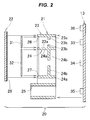
Fig. 2 is an exploded view of an assembly body; -
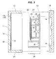
Fig. 3 is an exploded view (a cross-sectional view) of the vehicular display device according to the present invention; -
Fig. 4 is a cross-sectional view of the vehicular display device according to the present invention; -
Fig. 5 is a view as seen from an arrow 5 inFig. 4 ; -
Figs. 6A and 6B are views describing a display example in the vehicular display device; -
Figs. 7A and 7B are views describing a display example in the vehicular display device; -
Fig. 8 is a perspective view of a front portion of a saddle riding type vehicle; -
Fig. 9 is a cross-sectional view of the front portion of the saddle riding type vehicle; and -
Figs. 10A and 10B are views describing a basic principle of the prior art. - A description will be given below of an embodiment according to the present invention with reference to the accompanying drawings.
- As shown in
Fig. 1 , avehicular display device 10 is provided with anupper case 12 which has a horizontally long see-throughwindow 11, alower case 15 which has aboss 14 receiving acircuit board 13, and anassembly body 20 which is housed between theupper case 12 and thelower case 15. - The
upper case 12 has adisplay surface 16 which includes the see-throughwindow 11. Thedisplay surface 16 is provided with awarning display portion 50 in a lower side of the drawing in the see-throughwindow 11. In addition, thedisplay surface 16 has aleft arrow mark 17L (L is a subscript indicating left as seen from a driver, same applied to the below) which displays an actuation of a left direction indicator lamp and serves as a direction display portion in an upper left of the see-throughwindow 11, and has aright arrow mark 17R (R is a subscript indicating right as seen from the driver, same applied to the below) which displays an actuation of a right direction indicator lamp and serves as a direction display portion in an upper right of the see-throughwindow 11. - As shown in
Fig. 2 , theassembly body 20 is constructed by amiddle case 21, a liquidcrystal display panel 22 and thecircuit board 13. - The
middle case 21 is a resin molded product having a firstlight blocking wall 23 which is formed into a peripheral wall, a secondlight blocking wall 24 which is formed into a peripheral wall, and a thirdlight blocking wall 25 which is formed into a peripheral wall, and is made of an opaque resin material for maintaining a light blocking effect. - Describing in detail a structure of the first
light blocking wall 23 having the peripheral wall shape, the firstlight blocking wall 23 has awall 23a which is perpendicular to thecircuit board 13, and aparallel wall 23b which extends in parallel to thecircuit board 13 from the middle of theperpendicular wall 23a. - Describing in detail of a structure of the second
light blocking wall 24 having the peripheral wall shape in the same manner, the secondlight blocking wall 24 has awall 24a which is perpendicular to thecircuit board 13, and aparallel wall 24b which extends in parallel to thecircuit board 13 from the middle of theperpendicular wall 24a. - A
first frame portion 26 having a window frame shape is provided in one end of the firstlight blocking wall 23, and a firstlight diffuser panel 31 is fitted to thefirst frame portion 26. - A
second frame portion 27 having a window frame shape is provided in one end of the secondlight blocking wall 24, and a secondlight diffuser panel 32 is fitted to thesecond frame portion 27. - A semi-transmissive and
semi-reflective film 28 is affixed to a rear face of the liquidcrystal display panel 22. - Further, the
circuit board 13 is provided with a firstlight emitting device 33 at a position which is surrounded by the firstlight blocking wall 23, is provided with a secondlight emitting device 34 at a position which is surrounded by the secondlight blocking wall 24, is provided with a thirdlight emitting device 35 at a position which is surrounded by the thirdlight blocking wall 25, and is provided with a fourthlight emitting device 36 at an outside position of the firstlight blocking wall 23. - The first
light emitting device 33 is constructed by a multicolor LED (light emitting diode). - The second
light emitting device 34, the thirdlight emitting device 35 and the fourthlight emitting device 36 are constructed by an inexpensive monochromatic LED. - The
circuit board 13 is attached to themiddle case 21. Further, the liquidcrystal display panel 22 is attached to themiddle case 21 while fitting the firstlight diffuser panel 31 to thefirst frame portion 26, and fitting the secondlight diffuser panel 32 to thesecond frame portion 27. As a result, theassembly body 20 shown at the center ofFig. 3 can be obtained. - As shown in
Fig. 3 , aperipheral wall portion 37 extends from the periphery of thedisplay surface 16 to thelower case 15 side in theupper case 12. A black or graylight blocking layer 38 is formed by printing at the other positions than the see-throughwindow 11 on a rear face of thedisplay surface 16. - However, the
warning display portion 50 is formed so as to have a significantly thin film thickness. In the same manner, the arrow marks 17L and 17R are formed so as to have significantly thin film thicknesses. The significantly thin film may be constructed by a semitransparent film having the same color as thelight blocking layer 38. - As shown in
Fig. 4 , thevehicular display device 10 is provided with ahousing 39 which is constructed by theupper case 12 and thelower case 15, the liquidcrystal display panel 22 which is housed in thehousing 39, and thecircuit board 13 which is housed in thehousing 39. - The
circuit board 13 is provided with the firstlight emitting device 33 which can emit light with multiple colors, the secondlight emitting device 34 which emits light with a single color, the thirdlight emitting device 35 which emits light with a single color, and the fourthlight emitting device 36 which emits light with a single color. - The liquid
crystal display panel 22 is provided with the semi-transmissive andsemi-reflective film 28. - The
housing 39 has awarning display portion 50, and thewarning display portion 50 is transmitted and illuminated directly by the third light emitting device 35 (via no liquid crystal display panel 22). - As is apparent from the drawing, the sun light entering into the
housing 39 after passing through the see-throughwindow 11 is reflected by the semi-transmissive andsemi-reflective film 28. - Further, the illumination by the first
light emitting device 33 is diffused by the firstlight diffuser panel 31, passes through the semi-transmissive andsemi-reflective film 28, and illuminates the liquid crystal display panel 22 (accurately a first segment display portion mentioned later). The illumination by the secondlight emitting device 34 is diffused by the secondlight diffuser panel 32, passes through the semi-transmissive andsemi-reflective film 28 and illuminates the liquid crystal display panel 22 (accurately a second segment display portion mentioned later). - On the other hand, the illumination by the third
light emitting device 35 directly illuminates thewarning display portion 50. As a result, thewarning display portion 50 is displayed with high luminance. Since the illumination by the fourthlight emitting device 36 also illuminates the arrow marks 17L and 17R directly, the arrow marks 17L and 17R are displayed with high luminance. - As shown in
Fig. 5 , a main part of the liquidcrystal display panel 22 can be seen through the see-throughwindow 11. The substantial part of the liquidcrystal display panel 22 is provided, for example, with a firstsegment display portion 41 which graphically displays such as a rotating speed of an engine, and is also provided with a secondsegment display portion 42 which displays a speed of a vehicle with a numerical value. - A graphic like a sequential line graph is constructed by linearly arranging
display segments 43. Thedisplay segments 43 can be assumed as segments of a line, and the display portion having the aspect mentioned above is called as the firstsegment display portion 41. - In Arabic numerals, "1" is formed by arranging two I-
character display segments 44 up and down, and 0 to 9 are formed by arranging seven I-characterdisplay segments 44. The I-characterdisplay segments 44 are assumed as segments of numeric characters, and the display portion having the aspect mentioned above is called as the secondsegment display portion 42. - The
warning display portion 50 is constructed, for example, by ahigh beam mark 51, an ABS (antilock brake system)mark 52, aneutral mark 53, anoverheat mark 54 and anengine abnormality mark 55. They are normally invisible as shown by broken lines. Same applies to the left and right arrow marks 17L and 17R serving as the direction display portions. - As shown in
Fig. 4 , the secondlight emitting device 34 is arranged in the lower position of the firstlight emitting device 33, the third emittingdevice 35 is arranged in the lower position of the secondlight emitting device 34, and the fourthlight emitting device 36 is arranged in the upper position of the firstlight emitting device 33. - Then, the
warning display portion 50 illuminated by the third light emitting device is displayed in a lower edge of thevehicular display device 10, and the left and right arrow marks 17L and 17R serving as the direction display portions illuminated by the fourth light emitting device are displayed in an upper edge, as shown inFig. 5 . As a result, thewarning display portion 50 and thedirection display portions - Further, the
perpendicular walls circuit board 13 in their one ends, and come into contact with the liquidcrystal display panel 22 in their other ends. The light emitted by the firstlight emitting device 33 can be prevented from leaking to the adjacent display portion (reference numeral 42 inFig. 5 ), and the light emitted by the secondlight emitting device 34 can be prevented from leaking to the adjacent display portion (reference numeral 41 inFig. 5 ) in the same manner. - Further, the
perpendicular walls walls circuit board 13, as shown inFig. 4 . - The light emitted by the first and second
light emitting devices light diffuser panels parallel walls crystal display panel 22 is improved. - Further, the liquid
crystal display panel 22 is arranged between thecircuit board 13 and thewarning display portion 50 inFig. 4 . In other words, a distance H2 from thecircuit board 13 to thewarning display portion 50 is larger than a distance H1 from thecircuit board 13 to the liquid crystal display panel 20 (H1 < H2). - As shown in
Fig. 5 , the liquidcrystal display panel 22 has the firstsegment display portion 41 and the secondsegment display portion 42. Thewarning display portion 50 is arranged in a near side, and the firstsegment display portion 41 and the secondsegment display portion 42 are arranged in a far side of the drawing in comparison with thewarning display portion 50. On the basis of the eyes of the observer, such as the occupant, thewarning display portion 50 exists at a position which is slightly close to the eyes, and the first and secondsegment display portions - A description will be given next of an operation of the
vehicular display device 10 having the structure mentioned above. - As shown in
Fig. 6A , when the main switch is turned on from an off state, the firstsegment display portion 41 indicates that the rotating speed of the engine is zero. The secondsegment display portion 42 indicates that the speed of the vehicle is "0". In thewarning display portion 50, theneutral mark 53 is lighted and the selection of the neutral gear is indicated. - As shown in
Fig. 6B , when the engine is started, the firstsegment display portion 41 indicates that the engine is in an idle rotating state. When the driver changes the gear to low position, theneutral mark 53 goes out. When the driver turns on a right blinker, theright arrow mark 17R blinks. - As shown in
Fig. 7A , when the vehicle changes to the normal travel, the firstsegment display portion 41 displays the rotating speed of the engine. The color of the firstsegment display portion 41 is set to a safety color (blue or green). - The second
segment display portion 42 displays the speed of the vehicle. - In the case that the driver selects high beam, the
high beam mark 51 comes to a lighting state. As shown inFig. 4 , thewarning display portion 50 is illuminated by the thirdlight emitting device 35 directly via no liquidcrystal display panel 22. Therefore, thehigh beam mark 51 shown inFig. 7A is displayed with high luminance, and can be easily viewed even under sun light. Same applies to the otherwarning display portion 50. - If the gear ratio is erroneously selected under the high-speed traveling, the rotating speed of the engine may reach a critical rotating speed region.
- As shown in
Fig. 7B , the firstsegment display portion 41 lengthens fully and the display color changes from the safety color to a danger color (red). The driver immediately takes a step to decelerate the rotating speed of the engine. - In
Fig. 7B , the firstsegment display portion 41 is set to the multicolor display, however, the secondsegment display portion 42 set to the inexpensive monochromatic display. Therefore, cost increase of the liquidcrystal display panel 22 can be suppressed. - Next, a description will be given of an example in which the
vehicular display device 10 is mounted to the vehicle. - As shown in
Fig. 8 , the vehicle is a saddle ridingtype vehicle 60 which the driver gets on in a riding manner. The saddle ridingtype vehicle 60 is provided with afront cowl 61 in a front portion, is provided with left and rightdirection indicator lamps head lamp 63 in thefront cowl 61, and is provided with awind screen 64 shown by an imaginary line and astay 65 supporting thewind screen 64. - The
stay 65 is constructed by a pair of left and right risingportions front cowl 61, and abridging plate portion 67 which is bridged between a pair of risingportions - Further, the
vehicular display device 10 is arranged in an area which is surrounded by the risingportions bridging plate portion 67. - The
wind screen 64 has an openingportion 68 in a lower portion at the center. Thewind screen 64 is fastened to the risingportions members 69 such as screws. - As shown in
Fig. 9 , asteering handle 72 is attached to ahandle holder 71, thevehicular display device 10 is arranged in a vehicle forward side of thesteering handle 72, the bridgingplate portion 67 is arranged in a vehicle forward side of thevehicular display device 10, and thewind screen 64 is arranged in a front side of thebridging plate portion 67. - Traveling air flowing into from the opening
portion 68 of thewind screen 64 is guided by a front face of thebridging plate portion 67. - Pressure receiving area of the
wind screen 64 is reduced and the traveling resistance caused by the traveling air can be reduced, in the present embodiment having the openingportion 68, in comparison with the case that the openingportion 68 is not provided. - Further, vortex flow tends to be generated in an upper end of the
wind screen 64. A part of the traveling air taken into from the openingportion 68 is raised on a back face of thewind screen 64 while being guided by the bridgingplate portion 67. The vortex flow can be dissolved by the rising air flow. - The bridging
plate portion 67 provided for the purpose mentioned above extends upward so as to cover the above of thevehicular display device 10 after covering the vehicle forward side of thevehicular display device 10, as shown in the drawing. The upper half portion of thebridging plate portion 67 doubles as a sun visor, that is, a small shield over motorcycle gauges 73. It is possible to inhibit the sun light from directly reaching thevehicular display device 10 by means of the small shield over motorcycle gauges 73. - The first
segment display portion 41 may display an amount of fuel consumption in addition to the rotating speed of the engine. More specifically, the firstsegment display portion 41 is set to green when an economic drive is carried out, the firstsegment display portion 41 is set to red when an uneconomic drive is carried out, and the firstsegment display portion 41 is set to blue between them. As mentioned above, intended use of the firstsegment display portion 41 is optional. - The present invention is preferable for the vehicular display device including the liquid crystal display panel.
The invention provides an automotive display device which can achieve a colorful display and can achieve a warning display easily viewed even under sun light. A vehicular display device (10) has a housing (39), a liquid crystal display panel (22) which is housed in the housing (39), and a circuit board (13). The circuit board (13) has a first light emitting device (33) which can emit light with multiple colors, a second light emitting device (34) which emits light with a single color, a third light emitting device (35) which emits light with a single color, and a fourth light emitting device (36) which emits light with a single color. The liquid crystal display panel (22) has a semi-transmissive and semi-reflective film (28). The housing (39) has a warning display portion (50) which is transmitted and illuminated by the third light emitting device (35). Since the first light emitting device (33) can emit light with multiple colors, a colorful display can be achieved. Since illumination by the third light emitting device (35) illuminates the warning display portion (50) directly, the warning display portion (5) is displayed with high luminance, and is easily viewed even under sun light. -
- 10 vehicular display device
- 13 circuit board
- 17L, 17R direction display portion (arrow mark)
- 22 liquid crystal display panel
- 28 semi-transmissive and semi-reflective film
- 33 first light emitting device
- 34 second light emitting device
- 35 third light emitting device
- 36 fourth light emitting device
- 39 housing
- 41 first segment display portion
- 42 second segment display portion
- 50 warning display portion
- 60 saddle riding type vehicle
- 64 wind screen
- 72 steering handle
- 73 small shield over motorcycle gauges
Claims (7)
- A vehicular display device comprising:a housing;a liquid crystal display panel which is housed in the housing; anda circuit board which is housed in said housing,wherein said circuit board is provided with a first light emitting device which can emit light with multiple colors, a second light emitting device which emits light with a single color, and a third light emitting device which emits light with a single color,wherein said liquid crystal display panel is provided with a semi-transmissive and semi-reflective film, and has a first segment display portion which is transmitted and illuminated by said first light emitting device, and a second segment display portion which is transmitted and illuminated by said second light emitting device, andwherein said housing has a warning display portion which is transmitted and illuminated by said third light emitting device.
- The vehicular display device according to claim 1, wherein said first segment display portion indicates a rotating speed of an engine, and
wherein said second segment display portion indicates a speed of the vehicle. - The vehicular display device according to claim 1 or 2, wherein the vehicular display device is provided in a saddle riding type vehicle.
- The vehicular display device according to claim 3, wherein said vehicular display device is provided in a forward side of a steering handle of said saddle riding type vehicle and a rearward side of a wind screen.
- The vehicular display device according to claim 3 or 4, wherein said vehicular display device is provided with a small shield over motorcycle gauges which prevents direct projection of sun light.
- The vehicular display device according to claim 1, wherein said circuit board further comprises a fourth light emitting device which emits light with a single color,
wherein said housing further has a direction display portion which is transmitted and illuminated by said fourth light emitting device, and
wherein said second light emitting device is arranged at a lower position of said first light emitting device, said third light emitting device is arranged at a lower position of the second light emitting device, and the fourth light emitting device is arranged at an upper position of said first light emitting device. - The vehicular display device according to claim 1, wherein said liquid crystal display panel having said first segment display portion and said second segment display portion is arranged between said circuit board and said warning display portion.
Applications Claiming Priority (1)
| Application Number | Priority Date | Filing Date | Title |
|---|---|---|---|
| JP2015096650A JP6491532B2 (en) | 2015-05-11 | 2015-05-11 | Vehicle display device |
Publications (3)
| Publication Number | Publication Date |
|---|---|
| EP3093181A2 true EP3093181A2 (en) | 2016-11-16 |
| EP3093181A3 EP3093181A3 (en) | 2017-04-12 |
| EP3093181B1 EP3093181B1 (en) | 2018-12-26 |
Family
ID=56097990
Family Applications (1)
| Application Number | Title | Priority Date | Filing Date |
|---|---|---|---|
| EP16168695.1A Active EP3093181B1 (en) | 2015-05-11 | 2016-05-09 | Vehicular display device |
Country Status (2)
| Country | Link |
|---|---|
| EP (1) | EP3093181B1 (en) |
| JP (1) | JP6491532B2 (en) |
Cited By (19)
| Publication number | Priority date | Publication date | Assignee | Title |
|---|---|---|---|---|
| US11292343B2 (en) | 2016-07-05 | 2022-04-05 | Corning Incorporated | Cold-formed glass article and assembly process thereof |
| US11332011B2 (en) | 2017-07-18 | 2022-05-17 | Corning Incorporated | Cold forming of complexly curved glass articles |
| US11331886B2 (en) | 2016-06-28 | 2022-05-17 | Corning Incorporated | Laminating thin strengthened glass to curved molded plastic surface for decorative and display cover application |
| US11384001B2 (en) | 2016-10-25 | 2022-07-12 | Corning Incorporated | Cold-form glass lamination to a display |
| US11459268B2 (en) | 2017-09-12 | 2022-10-04 | Corning Incorporated | Tactile elements for deadfronted glass and methods of making the same |
| US11518146B2 (en) | 2018-07-16 | 2022-12-06 | Corning Incorporated | Method of forming a vehicle interior system |
| US11550148B2 (en) | 2017-11-30 | 2023-01-10 | Corning Incorporated | Vacuum mold apparatus, systems, and methods for forming curved mirrors |
| US11586306B2 (en) | 2017-01-03 | 2023-02-21 | Corning Incorporated | Vehicle interior systems having a curved cover glass and display or touch panel and methods for forming the same |
| US11597672B2 (en) | 2016-03-09 | 2023-03-07 | Corning Incorporated | Cold forming of complexly curved glass articles |
| US11660963B2 (en) | 2017-09-13 | 2023-05-30 | Corning Incorporated | Curved vehicle displays |
| US11685684B2 (en) | 2017-05-15 | 2023-06-27 | Corning Incorporated | Contoured glass articles and methods of making the same |
| US11685685B2 (en) | 2019-07-31 | 2023-06-27 | Corning Incorporated | Method and system for cold-forming glass |
| US11718071B2 (en) | 2018-03-13 | 2023-08-08 | Corning Incorporated | Vehicle interior systems having a crack resistant curved cover glass and methods for forming the same |
| US11745588B2 (en) | 2017-10-10 | 2023-09-05 | Corning Incorporated | Vehicle interior systems having a curved cover glass with improved reliability and methods for forming the same |
| US11767250B2 (en) | 2017-11-30 | 2023-09-26 | Corning Incorporated | Systems and methods for vacuum-forming aspheric mirrors |
| US11768369B2 (en) | 2017-11-21 | 2023-09-26 | Corning Incorporated | Aspheric mirror for head-up display system and methods for forming the same |
| US11772491B2 (en) | 2017-09-13 | 2023-10-03 | Corning Incorporated | Light guide-based deadfront for display, related methods and vehicle interior systems |
| US11772361B2 (en) | 2020-04-02 | 2023-10-03 | Corning Incorporated | Curved glass constructions and methods for forming same |
| US11899865B2 (en) | 2017-01-03 | 2024-02-13 | Corning Incorporated | Vehicle interior systems having a curved cover glass and a display or touch panel and methods for forming the same |
Families Citing this family (2)
| Publication number | Priority date | Publication date | Assignee | Title |
|---|---|---|---|---|
| CN113474243B (en) * | 2019-02-27 | 2023-03-21 | 本田技研工业株式会社 | Saddle-ride type vehicle |
| DE102021126623A1 (en) * | 2021-10-14 | 2023-04-20 | Bayerische Motoren Werke Aktiengesellschaft | Single-track vehicle with a vehicle status indicator |
Citations (2)
| Publication number | Priority date | Publication date | Assignee | Title |
|---|---|---|---|---|
| JP2001281001A (en) | 2000-03-30 | 2001-10-10 | Honda Motor Co Ltd | Display device for vehicle |
| JP2004226364A (en) | 2003-01-27 | 2004-08-12 | Denso Corp | Display for vehicle |
Family Cites Families (9)
| Publication number | Priority date | Publication date | Assignee | Title |
|---|---|---|---|---|
| JPS5918025A (en) * | 1982-07-23 | 1984-01-30 | Honda Motor Co Ltd | Liquid crystal type meter display for motorcycle |
| JPH10114241A (en) * | 1996-10-09 | 1998-05-06 | Kubota Corp | Display device of work vehicle |
| US7642730B2 (en) * | 2000-04-24 | 2010-01-05 | Philips Solid-State Lighting Solutions, Inc. | Methods and apparatus for conveying information via color of light |
| US7750821B1 (en) * | 2007-03-30 | 2010-07-06 | Yazaki North America, Inc. | System and method for instrument panel with color graphical display |
| JP2010175683A (en) * | 2009-01-28 | 2010-08-12 | Nippon Seiki Co Ltd | Display |
| US20110043348A1 (en) * | 2009-08-20 | 2011-02-24 | Michael Blackard | Shift Prompt System |
| US9145055B2 (en) * | 2009-12-03 | 2015-09-29 | Volkswagen Ag | Systems and methods for presenting information to an automobile driver |
| JP5577191B2 (en) * | 2010-08-24 | 2014-08-20 | 川崎重工業株式会社 | Display device |
| JP5974993B2 (en) * | 2013-07-11 | 2016-08-23 | 株式会社デンソー | Vehicle display device |
-
2015
- 2015-05-11 JP JP2015096650A patent/JP6491532B2/en active Active
-
2016
- 2016-05-09 EP EP16168695.1A patent/EP3093181B1/en active Active
Patent Citations (2)
| Publication number | Priority date | Publication date | Assignee | Title |
|---|---|---|---|---|
| JP2001281001A (en) | 2000-03-30 | 2001-10-10 | Honda Motor Co Ltd | Display device for vehicle |
| JP2004226364A (en) | 2003-01-27 | 2004-08-12 | Denso Corp | Display for vehicle |
Cited By (24)
| Publication number | Priority date | Publication date | Assignee | Title |
|---|---|---|---|---|
| US11597672B2 (en) | 2016-03-09 | 2023-03-07 | Corning Incorporated | Cold forming of complexly curved glass articles |
| US11331886B2 (en) | 2016-06-28 | 2022-05-17 | Corning Incorporated | Laminating thin strengthened glass to curved molded plastic surface for decorative and display cover application |
| US11338556B2 (en) | 2016-06-28 | 2022-05-24 | Corning Incorporated | Laminating thin strengthened glass to curved molded plastic surface for decorative and display cover application |
| US11292343B2 (en) | 2016-07-05 | 2022-04-05 | Corning Incorporated | Cold-formed glass article and assembly process thereof |
| US11850942B2 (en) | 2016-07-05 | 2023-12-26 | Corning Incorporated | Cold-formed glass article and assembly process thereof |
| US11607958B2 (en) | 2016-07-05 | 2023-03-21 | Corning Incorporated | Cold-formed glass article and assembly process thereof |
| US11384001B2 (en) | 2016-10-25 | 2022-07-12 | Corning Incorporated | Cold-form glass lamination to a display |
| US11586306B2 (en) | 2017-01-03 | 2023-02-21 | Corning Incorporated | Vehicle interior systems having a curved cover glass and display or touch panel and methods for forming the same |
| US11899865B2 (en) | 2017-01-03 | 2024-02-13 | Corning Incorporated | Vehicle interior systems having a curved cover glass and a display or touch panel and methods for forming the same |
| US11685684B2 (en) | 2017-05-15 | 2023-06-27 | Corning Incorporated | Contoured glass articles and methods of making the same |
| US11332011B2 (en) | 2017-07-18 | 2022-05-17 | Corning Incorporated | Cold forming of complexly curved glass articles |
| US11459268B2 (en) | 2017-09-12 | 2022-10-04 | Corning Incorporated | Tactile elements for deadfronted glass and methods of making the same |
| US11713276B2 (en) | 2017-09-12 | 2023-08-01 | Corning Incorporated | Tactile elements for deadfronted glass and methods of making the same |
| US11919396B2 (en) | 2017-09-13 | 2024-03-05 | Corning Incorporated | Curved vehicle displays |
| US11660963B2 (en) | 2017-09-13 | 2023-05-30 | Corning Incorporated | Curved vehicle displays |
| US11772491B2 (en) | 2017-09-13 | 2023-10-03 | Corning Incorporated | Light guide-based deadfront for display, related methods and vehicle interior systems |
| US11745588B2 (en) | 2017-10-10 | 2023-09-05 | Corning Incorporated | Vehicle interior systems having a curved cover glass with improved reliability and methods for forming the same |
| US11768369B2 (en) | 2017-11-21 | 2023-09-26 | Corning Incorporated | Aspheric mirror for head-up display system and methods for forming the same |
| US11767250B2 (en) | 2017-11-30 | 2023-09-26 | Corning Incorporated | Systems and methods for vacuum-forming aspheric mirrors |
| US11550148B2 (en) | 2017-11-30 | 2023-01-10 | Corning Incorporated | Vacuum mold apparatus, systems, and methods for forming curved mirrors |
| US11718071B2 (en) | 2018-03-13 | 2023-08-08 | Corning Incorporated | Vehicle interior systems having a crack resistant curved cover glass and methods for forming the same |
| US11518146B2 (en) | 2018-07-16 | 2022-12-06 | Corning Incorporated | Method of forming a vehicle interior system |
| US11685685B2 (en) | 2019-07-31 | 2023-06-27 | Corning Incorporated | Method and system for cold-forming glass |
| US11772361B2 (en) | 2020-04-02 | 2023-10-03 | Corning Incorporated | Curved glass constructions and methods for forming same |
Also Published As
| Publication number | Publication date |
|---|---|
| EP3093181B1 (en) | 2018-12-26 |
| JP6491532B2 (en) | 2019-03-27 |
| EP3093181A3 (en) | 2017-04-12 |
| JP2016210321A (en) | 2016-12-15 |
Similar Documents
| Publication | Publication Date | Title |
|---|---|---|
| EP3093181B1 (en) | Vehicular display device | |
| EP2498068B1 (en) | Meter | |
| EP2727758A2 (en) | Meter display device for vehicle | |
| JP5218194B2 (en) | Mobile instrument | |
| JP5083498B2 (en) | Lighting device | |
| JP5682549B2 (en) | Vehicle instrument | |
| KR100601685B1 (en) | Combination meter for cars | |
| KR20140052040A (en) | Display device for a vehicle | |
| JP5971179B2 (en) | Vehicle display device | |
| US8308312B2 (en) | Vehicle meter | |
| JP2007101358A (en) | Measuring instrument for vehicle | |
| JP2010134276A (en) | Display device for vehicle | |
| JP6615156B2 (en) | Vehicle display device | |
| JP7076066B2 (en) | Instrument | |
| JP5557095B2 (en) | Vehicle instrument | |
| JP6644349B2 (en) | Display device | |
| JP4652787B2 (en) | Display device | |
| JP5029521B2 (en) | Vehicle display device | |
| JP4912446B2 (en) | Liquid crystal display | |
| EP3184347B1 (en) | Vehicular instrument | |
| JP6997411B2 (en) | Display device | |
| JP2007256194A (en) | Pointer instrument for vehicle | |
| JP2013044672A (en) | Vehicle meter | |
| JP2004224233A (en) | Display device for vehicle | |
| JP2005309157A (en) | Display device |
Legal Events
| Date | Code | Title | Description |
|---|---|---|---|
| PUAI | Public reference made under article 153(3) epc to a published international application that has entered the european phase |
Free format text: ORIGINAL CODE: 0009012 |
|
| AK | Designated contracting states |
Kind code of ref document: A2 Designated state(s): AL AT BE BG CH CY CZ DE DK EE ES FI FR GB GR HR HU IE IS IT LI LT LU LV MC MK MT NL NO PL PT RO RS SE SI SK SM TR |
|
| AX | Request for extension of the european patent |
Extension state: BA ME |
|
| PUAL | Search report despatched |
Free format text: ORIGINAL CODE: 0009013 |
|
| AK | Designated contracting states |
Kind code of ref document: A3 Designated state(s): AL AT BE BG CH CY CZ DE DK EE ES FI FR GB GR HR HU IE IS IT LI LT LU LV MC MK MT NL NO PL PT RO RS SE SI SK SM TR |
|
| AX | Request for extension of the european patent |
Extension state: BA ME |
|
| RIC1 | Information provided on ipc code assigned before grant |
Ipc: B60K 35/00 20060101AFI20170306BHEP Ipc: B60K 37/02 20060101ALI20170306BHEP |
|
| STAA | Information on the status of an ep patent application or granted ep patent |
Free format text: STATUS: REQUEST FOR EXAMINATION WAS MADE |
|
| 17P | Request for examination filed |
Effective date: 20170505 |
|
| RBV | Designated contracting states (corrected) |
Designated state(s): AL AT BE BG CH CY CZ DE DK EE ES FI FR GB GR HR HU IE IS IT LI LT LU LV MC MK MT NL NO PL PT RO RS SE SI SK SM TR |
|
| STAA | Information on the status of an ep patent application or granted ep patent |
Free format text: STATUS: EXAMINATION IS IN PROGRESS |
|
| 17Q | First examination report despatched |
Effective date: 20171025 |
|
| GRAP | Despatch of communication of intention to grant a patent |
Free format text: ORIGINAL CODE: EPIDOSNIGR1 |
|
| STAA | Information on the status of an ep patent application or granted ep patent |
Free format text: STATUS: GRANT OF PATENT IS INTENDED |
|
| INTG | Intention to grant announced |
Effective date: 20180713 |
|
| GRAS | Grant fee paid |
Free format text: ORIGINAL CODE: EPIDOSNIGR3 |
|
| GRAA | (expected) grant |
Free format text: ORIGINAL CODE: 0009210 |
|
| STAA | Information on the status of an ep patent application or granted ep patent |
Free format text: STATUS: THE PATENT HAS BEEN GRANTED |
|
| AK | Designated contracting states |
Kind code of ref document: B1 Designated state(s): AL AT BE BG CH CY CZ DE DK EE ES FI FR GB GR HR HU IE IS IT LI LT LU LV MC MK MT NL NO PL PT RO RS SE SI SK SM TR |
|
| REG | Reference to a national code |
Ref country code: GB Ref legal event code: FG4D |
|
| REG | Reference to a national code |
Ref country code: CH Ref legal event code: EP |
|
| REG | Reference to a national code |
Ref country code: AT Ref legal event code: REF Ref document number: 1080929 Country of ref document: AT Kind code of ref document: T Effective date: 20190115 |
|
| REG | Reference to a national code |
Ref country code: IE Ref legal event code: FG4D |
|
| REG | Reference to a national code |
Ref country code: DE Ref legal event code: R096 Ref document number: 602016008577 Country of ref document: DE |
|
| PG25 | Lapsed in a contracting state [announced via postgrant information from national office to epo] |
Ref country code: LV Free format text: LAPSE BECAUSE OF FAILURE TO SUBMIT A TRANSLATION OF THE DESCRIPTION OR TO PAY THE FEE WITHIN THE PRESCRIBED TIME-LIMIT Effective date: 20181226 Ref country code: NO Free format text: LAPSE BECAUSE OF FAILURE TO SUBMIT A TRANSLATION OF THE DESCRIPTION OR TO PAY THE FEE WITHIN THE PRESCRIBED TIME-LIMIT Effective date: 20190326 Ref country code: FI Free format text: LAPSE BECAUSE OF FAILURE TO SUBMIT A TRANSLATION OF THE DESCRIPTION OR TO PAY THE FEE WITHIN THE PRESCRIBED TIME-LIMIT Effective date: 20181226 Ref country code: LT Free format text: LAPSE BECAUSE OF FAILURE TO SUBMIT A TRANSLATION OF THE DESCRIPTION OR TO PAY THE FEE WITHIN THE PRESCRIBED TIME-LIMIT Effective date: 20181226 Ref country code: HR Free format text: LAPSE BECAUSE OF FAILURE TO SUBMIT A TRANSLATION OF THE DESCRIPTION OR TO PAY THE FEE WITHIN THE PRESCRIBED TIME-LIMIT Effective date: 20181226 Ref country code: BG Free format text: LAPSE BECAUSE OF FAILURE TO SUBMIT A TRANSLATION OF THE DESCRIPTION OR TO PAY THE FEE WITHIN THE PRESCRIBED TIME-LIMIT Effective date: 20190326 |
|
| REG | Reference to a national code |
Ref country code: NL Ref legal event code: MP Effective date: 20181226 |
|
| REG | Reference to a national code |
Ref country code: LT Ref legal event code: MG4D |
|
| PG25 | Lapsed in a contracting state [announced via postgrant information from national office to epo] |
Ref country code: RS Free format text: LAPSE BECAUSE OF FAILURE TO SUBMIT A TRANSLATION OF THE DESCRIPTION OR TO PAY THE FEE WITHIN THE PRESCRIBED TIME-LIMIT Effective date: 20181226 Ref country code: GR Free format text: LAPSE BECAUSE OF FAILURE TO SUBMIT A TRANSLATION OF THE DESCRIPTION OR TO PAY THE FEE WITHIN THE PRESCRIBED TIME-LIMIT Effective date: 20190327 Ref country code: SE Free format text: LAPSE BECAUSE OF FAILURE TO SUBMIT A TRANSLATION OF THE DESCRIPTION OR TO PAY THE FEE WITHIN THE PRESCRIBED TIME-LIMIT Effective date: 20181226 Ref country code: AL Free format text: LAPSE BECAUSE OF FAILURE TO SUBMIT A TRANSLATION OF THE DESCRIPTION OR TO PAY THE FEE WITHIN THE PRESCRIBED TIME-LIMIT Effective date: 20181226 |
|
| REG | Reference to a national code |
Ref country code: AT Ref legal event code: MK05 Ref document number: 1080929 Country of ref document: AT Kind code of ref document: T Effective date: 20181226 |
|
| PG25 | Lapsed in a contracting state [announced via postgrant information from national office to epo] |
Ref country code: NL Free format text: LAPSE BECAUSE OF FAILURE TO SUBMIT A TRANSLATION OF THE DESCRIPTION OR TO PAY THE FEE WITHIN THE PRESCRIBED TIME-LIMIT Effective date: 20181226 |
|
| PG25 | Lapsed in a contracting state [announced via postgrant information from national office to epo] |
Ref country code: ES Free format text: LAPSE BECAUSE OF FAILURE TO SUBMIT A TRANSLATION OF THE DESCRIPTION OR TO PAY THE FEE WITHIN THE PRESCRIBED TIME-LIMIT Effective date: 20181226 Ref country code: PL Free format text: LAPSE BECAUSE OF FAILURE TO SUBMIT A TRANSLATION OF THE DESCRIPTION OR TO PAY THE FEE WITHIN THE PRESCRIBED TIME-LIMIT Effective date: 20181226 Ref country code: CZ Free format text: LAPSE BECAUSE OF FAILURE TO SUBMIT A TRANSLATION OF THE DESCRIPTION OR TO PAY THE FEE WITHIN THE PRESCRIBED TIME-LIMIT Effective date: 20181226 Ref country code: PT Free format text: LAPSE BECAUSE OF FAILURE TO SUBMIT A TRANSLATION OF THE DESCRIPTION OR TO PAY THE FEE WITHIN THE PRESCRIBED TIME-LIMIT Effective date: 20190426 Ref country code: IT Free format text: LAPSE BECAUSE OF FAILURE TO SUBMIT A TRANSLATION OF THE DESCRIPTION OR TO PAY THE FEE WITHIN THE PRESCRIBED TIME-LIMIT Effective date: 20181226 |
|
| PG25 | Lapsed in a contracting state [announced via postgrant information from national office to epo] |
Ref country code: RO Free format text: LAPSE BECAUSE OF FAILURE TO SUBMIT A TRANSLATION OF THE DESCRIPTION OR TO PAY THE FEE WITHIN THE PRESCRIBED TIME-LIMIT Effective date: 20181226 Ref country code: SK Free format text: LAPSE BECAUSE OF FAILURE TO SUBMIT A TRANSLATION OF THE DESCRIPTION OR TO PAY THE FEE WITHIN THE PRESCRIBED TIME-LIMIT Effective date: 20181226 Ref country code: IS Free format text: LAPSE BECAUSE OF FAILURE TO SUBMIT A TRANSLATION OF THE DESCRIPTION OR TO PAY THE FEE WITHIN THE PRESCRIBED TIME-LIMIT Effective date: 20190426 Ref country code: EE Free format text: LAPSE BECAUSE OF FAILURE TO SUBMIT A TRANSLATION OF THE DESCRIPTION OR TO PAY THE FEE WITHIN THE PRESCRIBED TIME-LIMIT Effective date: 20181226 Ref country code: SM Free format text: LAPSE BECAUSE OF FAILURE TO SUBMIT A TRANSLATION OF THE DESCRIPTION OR TO PAY THE FEE WITHIN THE PRESCRIBED TIME-LIMIT Effective date: 20181226 |
|
| REG | Reference to a national code |
Ref country code: DE Ref legal event code: R097 Ref document number: 602016008577 Country of ref document: DE |
|
| PG25 | Lapsed in a contracting state [announced via postgrant information from national office to epo] |
Ref country code: DK Free format text: LAPSE BECAUSE OF FAILURE TO SUBMIT A TRANSLATION OF THE DESCRIPTION OR TO PAY THE FEE WITHIN THE PRESCRIBED TIME-LIMIT Effective date: 20181226 Ref country code: AT Free format text: LAPSE BECAUSE OF FAILURE TO SUBMIT A TRANSLATION OF THE DESCRIPTION OR TO PAY THE FEE WITHIN THE PRESCRIBED TIME-LIMIT Effective date: 20181226 |
|
| PLBE | No opposition filed within time limit |
Free format text: ORIGINAL CODE: 0009261 |
|
| STAA | Information on the status of an ep patent application or granted ep patent |
Free format text: STATUS: NO OPPOSITION FILED WITHIN TIME LIMIT |
|
| 26N | No opposition filed |
Effective date: 20190927 |
|
| REG | Reference to a national code |
Ref country code: DE Ref legal event code: R084 Ref document number: 602016008577 Country of ref document: DE |
|
| REG | Reference to a national code |
Ref country code: CH Ref legal event code: PL |
|
| PG25 | Lapsed in a contracting state [announced via postgrant information from national office to epo] |
Ref country code: CH Free format text: LAPSE BECAUSE OF NON-PAYMENT OF DUE FEES Effective date: 20190531 Ref country code: MC Free format text: LAPSE BECAUSE OF FAILURE TO SUBMIT A TRANSLATION OF THE DESCRIPTION OR TO PAY THE FEE WITHIN THE PRESCRIBED TIME-LIMIT Effective date: 20181226 Ref country code: LI Free format text: LAPSE BECAUSE OF NON-PAYMENT OF DUE FEES Effective date: 20190531 |
|
| REG | Reference to a national code |
Ref country code: BE Ref legal event code: MM Effective date: 20190531 |
|
| PG25 | Lapsed in a contracting state [announced via postgrant information from national office to epo] |
Ref country code: SI Free format text: LAPSE BECAUSE OF FAILURE TO SUBMIT A TRANSLATION OF THE DESCRIPTION OR TO PAY THE FEE WITHIN THE PRESCRIBED TIME-LIMIT Effective date: 20181226 Ref country code: LU Free format text: LAPSE BECAUSE OF NON-PAYMENT OF DUE FEES Effective date: 20190509 |
|
| PG25 | Lapsed in a contracting state [announced via postgrant information from national office to epo] |
Ref country code: TR Free format text: LAPSE BECAUSE OF FAILURE TO SUBMIT A TRANSLATION OF THE DESCRIPTION OR TO PAY THE FEE WITHIN THE PRESCRIBED TIME-LIMIT Effective date: 20181226 |
|
| PG25 | Lapsed in a contracting state [announced via postgrant information from national office to epo] |
Ref country code: IE Free format text: LAPSE BECAUSE OF NON-PAYMENT OF DUE FEES Effective date: 20190509 |
|
| PG25 | Lapsed in a contracting state [announced via postgrant information from national office to epo] |
Ref country code: BE Free format text: LAPSE BECAUSE OF NON-PAYMENT OF DUE FEES Effective date: 20190531 |
|
| PG25 | Lapsed in a contracting state [announced via postgrant information from national office to epo] |
Ref country code: FR Free format text: LAPSE BECAUSE OF NON-PAYMENT OF DUE FEES Effective date: 20190531 |
|
| GBPC | Gb: european patent ceased through non-payment of renewal fee |
Effective date: 20200509 |
|
| PG25 | Lapsed in a contracting state [announced via postgrant information from national office to epo] |
Ref country code: GB Free format text: LAPSE BECAUSE OF NON-PAYMENT OF DUE FEES Effective date: 20200509 |
|
| PG25 | Lapsed in a contracting state [announced via postgrant information from national office to epo] |
Ref country code: CY Free format text: LAPSE BECAUSE OF FAILURE TO SUBMIT A TRANSLATION OF THE DESCRIPTION OR TO PAY THE FEE WITHIN THE PRESCRIBED TIME-LIMIT Effective date: 20181226 |
|
| PG25 | Lapsed in a contracting state [announced via postgrant information from national office to epo] |
Ref country code: HU Free format text: LAPSE BECAUSE OF FAILURE TO SUBMIT A TRANSLATION OF THE DESCRIPTION OR TO PAY THE FEE WITHIN THE PRESCRIBED TIME-LIMIT; INVALID AB INITIO Effective date: 20160509 Ref country code: MT Free format text: LAPSE BECAUSE OF FAILURE TO SUBMIT A TRANSLATION OF THE DESCRIPTION OR TO PAY THE FEE WITHIN THE PRESCRIBED TIME-LIMIT Effective date: 20181226 |
|
| PG25 | Lapsed in a contracting state [announced via postgrant information from national office to epo] |
Ref country code: MK Free format text: LAPSE BECAUSE OF FAILURE TO SUBMIT A TRANSLATION OF THE DESCRIPTION OR TO PAY THE FEE WITHIN THE PRESCRIBED TIME-LIMIT Effective date: 20181226 |
|
| PGFP | Annual fee paid to national office [announced via postgrant information from national office to epo] |
Ref country code: DE Payment date: 20230314 Year of fee payment: 8 |