EP3092025B1 - Package having integral tab with finger hole opening feature - Google Patents
Package having integral tab with finger hole opening feature Download PDFInfo
- Publication number
- EP3092025B1 EP3092025B1 EP15701868.0A EP15701868A EP3092025B1 EP 3092025 B1 EP3092025 B1 EP 3092025B1 EP 15701868 A EP15701868 A EP 15701868A EP 3092025 B1 EP3092025 B1 EP 3092025B1
- Authority
- EP
- European Patent Office
- Prior art keywords
- fin
- package
- panels
- line
- seal
- Prior art date
- Legal status (The legal status is an assumption and is not a legal conclusion. Google has not performed a legal analysis and makes no representation as to the accuracy of the status listed.)
- Active
Links
- 239000007858 starting material Substances 0.000 claims description 37
- 239000000463 material Substances 0.000 claims description 34
- 238000007789 sealing Methods 0.000 claims description 13
- 238000004519 manufacturing process Methods 0.000 claims description 6
- 238000000034 method Methods 0.000 claims description 4
- 239000002356 single layer Substances 0.000 claims 1
- 239000000853 adhesive Substances 0.000 description 5
- 230000001070 adhesive effect Effects 0.000 description 5
- 230000015572 biosynthetic process Effects 0.000 description 4
- 238000004080 punching Methods 0.000 description 3
- 230000005856 abnormality Effects 0.000 description 2
- 230000004048 modification Effects 0.000 description 2
- 238000012986 modification Methods 0.000 description 2
- 208000031872 Body Remains Diseases 0.000 description 1
- 230000009471 action Effects 0.000 description 1
- 238000013459 approach Methods 0.000 description 1
- 230000008901 benefit Effects 0.000 description 1
- 239000011248 coating agent Substances 0.000 description 1
- 238000000576 coating method Methods 0.000 description 1
- 238000012217 deletion Methods 0.000 description 1
- 230000037430 deletion Effects 0.000 description 1
- 238000013461 design Methods 0.000 description 1
- 239000011888 foil Substances 0.000 description 1
- 238000003698 laser cutting Methods 0.000 description 1
- 238000004806 packaging method and process Methods 0.000 description 1
- 238000002360 preparation method Methods 0.000 description 1
- 230000008569 process Effects 0.000 description 1
- 230000001902 propagating effect Effects 0.000 description 1
- 238000000926 separation method Methods 0.000 description 1
- 239000007787 solid Substances 0.000 description 1
- 230000007704 transition Effects 0.000 description 1
- 230000002485 urinary effect Effects 0.000 description 1
- 230000003313 weakening effect Effects 0.000 description 1
Images


Classifications
-
- B—PERFORMING OPERATIONS; TRANSPORTING
- B65—CONVEYING; PACKING; STORING; HANDLING THIN OR FILAMENTARY MATERIAL
- B65D—CONTAINERS FOR STORAGE OR TRANSPORT OF ARTICLES OR MATERIALS, e.g. BAGS, BARRELS, BOTTLES, BOXES, CANS, CARTONS, CRATES, DRUMS, JARS, TANKS, HOPPERS, FORWARDING CONTAINERS; ACCESSORIES, CLOSURES, OR FITTINGS THEREFOR; PACKAGING ELEMENTS; PACKAGES
- B65D75/00—Packages comprising articles or materials partially or wholly enclosed in strips, sheets, blanks, tubes, or webs of flexible sheet material, e.g. in folded wrappers
- B65D75/52—Details
- B65D75/58—Opening or contents-removing devices added or incorporated during package manufacture
- B65D75/5827—Tear-lines provided in a wall portion
- B65D75/5833—Tear-lines provided in a wall portion for tearing out a portion of the wall
- B65D75/5838—Tear-lines provided in a wall portion for tearing out a portion of the wall combined with separate fixed tearing means, e.g. tabs
-
- A—HUMAN NECESSITIES
- A61—MEDICAL OR VETERINARY SCIENCE; HYGIENE
- A61M—DEVICES FOR INTRODUCING MEDIA INTO, OR ONTO, THE BODY; DEVICES FOR TRANSDUCING BODY MEDIA OR FOR TAKING MEDIA FROM THE BODY; DEVICES FOR PRODUCING OR ENDING SLEEP OR STUPOR
- A61M25/00—Catheters; Hollow probes
- A61M25/0017—Catheters; Hollow probes specially adapted for long-term hygiene care, e.g. urethral or indwelling catheters to prevent infections
-
- A—HUMAN NECESSITIES
- A61—MEDICAL OR VETERINARY SCIENCE; HYGIENE
- A61M—DEVICES FOR INTRODUCING MEDIA INTO, OR ONTO, THE BODY; DEVICES FOR TRANSDUCING BODY MEDIA OR FOR TAKING MEDIA FROM THE BODY; DEVICES FOR PRODUCING OR ENDING SLEEP OR STUPOR
- A61M25/00—Catheters; Hollow probes
- A61M25/002—Packages specially adapted therefor ; catheter kit packages
-
- B—PERFORMING OPERATIONS; TRANSPORTING
- B65—CONVEYING; PACKING; STORING; HANDLING THIN OR FILAMENTARY MATERIAL
- B65D—CONTAINERS FOR STORAGE OR TRANSPORT OF ARTICLES OR MATERIALS, e.g. BAGS, BARRELS, BOTTLES, BOXES, CANS, CARTONS, CRATES, DRUMS, JARS, TANKS, HOPPERS, FORWARDING CONTAINERS; ACCESSORIES, CLOSURES, OR FITTINGS THEREFOR; PACKAGING ELEMENTS; PACKAGES
- B65D75/00—Packages comprising articles or materials partially or wholly enclosed in strips, sheets, blanks, tubes, or webs of flexible sheet material, e.g. in folded wrappers
- B65D75/04—Articles or materials wholly enclosed in single sheets or wrapper blanks
- B65D75/06—Articles or materials wholly enclosed in single sheets or wrapper blanks in sheets or blanks initially folded to form tubes
-
- B—PERFORMING OPERATIONS; TRANSPORTING
- B65—CONVEYING; PACKING; STORING; HANDLING THIN OR FILAMENTARY MATERIAL
- B65D—CONTAINERS FOR STORAGE OR TRANSPORT OF ARTICLES OR MATERIALS, e.g. BAGS, BARRELS, BOTTLES, BOXES, CANS, CARTONS, CRATES, DRUMS, JARS, TANKS, HOPPERS, FORWARDING CONTAINERS; ACCESSORIES, CLOSURES, OR FITTINGS THEREFOR; PACKAGING ELEMENTS; PACKAGES
- B65D75/00—Packages comprising articles or materials partially or wholly enclosed in strips, sheets, blanks, tubes, or webs of flexible sheet material, e.g. in folded wrappers
- B65D75/52—Details
- B65D75/58—Opening or contents-removing devices added or incorporated during package manufacture
- B65D75/5827—Tear-lines provided in a wall portion
- B65D75/5833—Tear-lines provided in a wall portion for tearing out a portion of the wall
Definitions
- the present disclosure is generally related to packaging and more particularly to a package for elongated articles such as catheters.
- Intermittent catheterization is a good option for many people who suffer from various abnormalities of the urinary system. Those with such abnormalities often find it desirable to use individually-packaged, sterile catheters designed for a single use.
- An important criteria for such a single use product includes the cost and ease of use in performing intermittent catheterization. With regard to both cost and ease of use, these factors apply to both the catheter itself and the package for the catheter. It is desirable that end users find the package acceptable to enhance the chances of successful intermittent catheterization.
- an important factor in catheter package design is recognition that some catheter users will have limited manual dexterity, which can make it difficult for them to open a conventional package.
- U.S. Patent No. 7,770,726 One type of known catheter package is shown in U.S. Patent No. 7,770,726 .
- the package in this patent uses a tear strip located inside the package at one edge and running essentially the entire length of the package.
- the tear strip is anchored at one end to an end seal.
- a portion of the end seal with the tear strip attached is severable from the package which allows the user to grasp the end seal portion and use it to pull the tear strip down the length of the package.
- the tear strip severs the material of the body of the package and causes the package to open.
- WO 01/52763 A1 discloses a further prior art catheter package and method
- WO 2008/029106 A1 discloses an easy-open package for products.
- the present disclosure is directed to a package formed of an elongated sheet material wrapped about a product such as a catheter.
- the wrapped sheet material forms a package body which defines a cavity for receiving the product.
- Side panels of the wrapped sheet material are in contact with one another to define a fin.
- At least a portion of the contacting side panels of the fin are sealed together to define a fin seal.
- the fin and fin seal extend along the full length of the package.
- the fin may be connected to the package body at a fold line. The edges of the fin not at the fold line define a free edge of the fin.
- first and second end seals The ends of the package are closed by first and second end seals.
- the end seals may be formed by pinching the end portions of the sheet material that are opposite the fin toward the fin until adjacent portions of the sheet material are in contact with one another. These contacting end portions may then be sealed together in a direction transverse to the length of the package.
- a pull tab is formed in the fin by a starter line that extends from the free edge of the fin toward the fold line.
- the starter line can be cut fully through the fin, or it can be a score line that weakens the fin but is not cut fully through, or it can be a perforated line, or a combination of these.
- the starter line defines a pull tab which can be engaged by a user to enable him or her to pull on the fin and remove at least the fin seal from the majority of the package and thereby open the package. When the fin is used to tear open the package a clean, straight tear is consistently achieved.
- a finger hole may be included in the pull tab to promote easy opening of the package.
- a second finger hole may be included in an end seal.
- Fig. 1 shows an embodiment of the package 10 of the present invention.
- the package may be formed by wrapping an elongated sheet material around a catheter or other elongated product (not shown).
- the wrapped sheet includes a body 12 which defines a three-dimensional cavity 14 therein for receiving the product.
- the body 12 joins a first end seal 16 at one end and a second end seal 18 located at the opposite end of the package. The boundaries of the first and second end seals are shown at 16a and 18a, respectively.
- a longitudinal fin 20 extends the length of the package. As will be more fully explained below, the fin may be formed by confronting side panels of the wrapped sheet material.
- the fin 20 is joined to the body 12 and end seals 16, 18 at a fold line 22.
- the boundaries of the fin not at the fold line 22 define a free edge.
- the fin has both a longitudinal free edge 24 and two end free edges 26. While the end free edges are conveniently made to be perpendicular to the longitudinal free edge as shown, one or both of the end free edges could have a different configuration, such as a curved portion that merges with the longitudinal free edge.
- FIG. 2-5 Other views of the package 10 are shown in Figs. 2-5 .
- At least a portion of the confronting side panels of the fin 20 are held in contact with one another and sealed at a fin seal 28.
- the fin seal extends from the longitudinal free edge 24 to a fin seal terminal line shown at 30.
- the fin seal 28 could be located differently on the fin 20.
- the fin seal could extend fully from the free edge 24 to the fold line 22.
- the fin seal could extend from the fold line 22 partially toward the free edge 24.
- a pull tab 34 is formed in the fin 20 by a starter line 36 that extends to one of the free edges of the fin, in this case the longitudinal free edge 24.
- the starter line as shown at 36 may be a generally semi-circular cut fully through the thickness of the fin 20 and extends to or near the fold line 22 in the area of the first end seal 16.
- the starter line will extend to a single-sealed area of the fin, as will be more fully explained below. This means the starter line will approach the fold line 22 to about 6.4 mm (about a quarter inch) from the fold line, although it could stop short of that.
- the last portion, that is 6.4 mm or so (e.g., a quarter inch or so), of the internal end of the starter line be directed within 15 to 20 degrees of parallel to the fold line 22, although other arrangements are possible. This will tend to direct the intentional opening tear line along the fold line 22 and fin seal terminal line 30.
- the starter line 36 does not extend on to any portion of the end seal 16; only the fin 20 has the starter line. Furthermore, the starter line 36 extends all the way to a free edge 24 or 26 of the fin 20 to facilitate the beginning of an opening tear. While the starter line extends to a fin free edge, it does not have to be a complete cut through the full thickness of the fin. It could be an alternate form of weakening the fin to enable a tear to be started readily.
- the starter line 36 could be a score line only partially through the thickness of the fin, e.g., through one of the two layers of the sheet material that comprise the fin. The score line weakens the fin to enable starting of a tear but is not cut fully through the fin.
- starter line may include a perforated line, or a combination of perforations, scores and cuts.
- starter line defines the pull tab 34 which can be engaged by a user. This allows the user to pull on the fin and use it as a tear strip that removes at least the fin seal 28 from the package and thereby opens the package.
- Engagement with the pull tab 34 can be enhanced by forming a first finger hole 38 in the pull tab.
- the first finger hole 38 is formed entirely within the fin 20.
- a second finger hole 40 may be formed in the first end seal 16. Note that a portion 40a of the second finger hole extends onto the fin 20. Providing two finger holes allows the user to engage the fin with one hand and the end seal with the other hand and pull the two pieces apart, which removes the fin seal 28 from the package and lays it open for removal of the catheter.
- FIGs. 2 - 5 show the package 10 somewhat diagrammatically in that the boundaries of the actual body portion 12 do not necessarily have sharply defined edges as the drawings might suggest. Because the body has a three-dimensional shape that merges to flat portions at the end seals 16, 18, the actual transition from one portion of the body to another is somewhat more gradual than implied by the drawings.
- the sheet material 42 may be a gas impermeable foil that may be coated with a heat seal layer. It may be a directional tear material, although other materials could be used.
- the sheet material is shown having longitudinal panels or areas 1 - 6 which are divided by imaginary demarcation lines A - E.
- the panels may be designated as side panels 1 and 6, upper panels 2 and 5 and lower panels 3 and 4.
- the side panels 1 and 6 have longitudinal side edges 44 and 46, respectively.
- the sheet material 42 of course has top and bottom surfaces, which will become inside and outside surfaces of the package.
- inside surfaces are indicated with dotted reference numerals while the outside surfaces will be shown in subsequent figures in solid reference numerals.
- all or a portion of the inside surfaces may have an adhesive coating or heat seal layer thereon.
- this is a heat-activated adhesive that will adhere to at least other similarly coated surfaces when pressed against such surfaces and heated.
- Other types of adhesives could be used.
- Figs. 6 - 7 show just a single package, it will be understood that the manufacturing process described below is advantageously performed in a continuous manner. That is, an endless roll of sheet material is fed successively to a series of forming stations, (e.g., stations for wrapping, fin sealing, pinching, end sealing, punching, etc.), with individual packages not being separated from the endless roll until they have passed through all of the stations.
- a series of forming stations e.g., stations for wrapping, fin sealing, pinching, end sealing, punching, etc.
- Package formation may begin by unrolling the sheet material into a flat, generally horizontal condition with a front or leading edge 48 that will be fed to successive forming stations or zones.
- a catheter (not shown) is placed on the inside surface of the sheet material 42, at or near the longitudinal center line C of the sheet.
- the sheet material, with the catheter on its inside surface is then advanced to a wrapping station or zone wherein the sides of the sheet 42 are wrapped or folded up and around the catheter.
- the inside surfaces of just the side panels 1 and 6 are placed in confronting relation, with the side edges 44 and 46 brought into or near alignment with one another. This creates the tubular body 12 and the fin 20 of the package.
- the fin 20 passes through a sealing station where rollers or the like create the fold line 22 and the fin seal 28.
- the fin seal is created by heated rollers that activate the adhesive on portions of the inside surfaces of side panels 1 and 6.
- the fin seal portion is indicated in Fig. 7 by the cross-hatched area.
- This process defines the longitudinal free edge 24 of the fin and the fin seal terminal line 30.
- a further alternate embodiment would entail formation of the starter line 36 and finger hole 38 during fin sealing, as explained further below.
- Fig. 7 illustrates the package at this stage of its manufacture.
- the side panels 1 and 6 are in confronting relation and fold line 22 is formed along demarcation lines A and E.
- panels 1 and 6 define the fin 20.
- the cross-hatched portions of the inside surfaces of panels 1 and 6 are sealed to one another to define the fin seal 28.
- the lower portions of the inside surfaces of panels 1 and 6, i.e., the portion between fin seal terminal line 30 and fold line 22, are in confronting relation but they are not sealed to one another; they define the non-sealed portion 32 of the fin 20.
- the non-sealed portions 32 of panels 1 and 6 may or may not be touching one another, depending on how the body 12 is or is not stretched. But in any event the non-sealed portions of panels 1 and 2 are not adhered to one another.
- FIG. 7 note that upper panels 2 and 5 extend from the fold line 22 at demarcation lines A and E.
- Lower panels 3 and 4 extend from upper panels 2 and 5 at demarcation lines B and D, respectively.
- Lower panels 3 and 4 are joined at the bottom of the package at demarcation line C.
- the package body 12 is formed by panels 2, 3, 4 and 5. These panels are folded generally at the demarcation lines A - E to create the three-dimensional interior cavity 14 in which the catheter resides. Again, the actual package may not have panel boundaries as sharply defined as the figures might suggest.
- the next step in the manufacturing process is preparation for creation of the first and second end seals 16 and 18. This is done at a pinching zone where portions of the upper and lower panels of the sheet material are all placed in a generally flat condition, with the upper and lower panels confronting one another. Pinching is done only at selected, spaced locations along the sheet material, leaving intervening sections of panels 2 - 5 free to form the three-dimensional package body 12. As indicated schematically in Fig. 8 , the first end seal 16 of a leading package 10a is formed simultaneously with the immediately-adjacent second end seal 18 of a successive, trailing package 10b.
- both of the end seals are created at a single pinching and end sealing zone but the single sealing zone creates end seals for what will become separate packages.
- the leading and trailing packages 10a and 10b are subsequently separated from one another at a final severing station.
- portions of the body panels 2, 3, 4 and 5 are pinched together into a generally horizontal condition.
- the inside surfaces of panels 2 and 3 are placed in contact with one another, as are the inside surfaces of panels 4 and 5.
- the fin 20 is folded down into a generally horizontal condition. Folding of the fin may be done either before, during or after the pinching operation of panels 2 - 5.
- the sheet enters the end seal station.
- transverse rollers contact the pinched portions to form the first end seal 16 of a leading package and the second end seal 18 of a trailing package.
- the end seals 16, 18 are shown in Fig. 8 by the cross-hatching that is in a different direction from that of the fin seal 28.
- the end sealing rollers will also cross over the folded-down fin 20, resulting in: a) a double-sealed area 50 (as indicated at the double cross-hatched areas) of the fin panels 1 and 6 at the area of the fin seal 28; and b) a single-sealed area 52 (as indicated at the single cross-hatched area of the fin) of the fin panels 1 and 6 between the fold line 22 and the fin seal terminal line 30.
- this single-sealed area 52 was part of the non-sealed portion of the fin.
- the single-sealed area of the fin is shown at 52 and exists only at the area of the end seals 16 and 18.
- the second finger hole 40 can also be formed at this time.
- the second finger hole 40 can be formed by a simple punching operation that extends through both the first end seal 16 and the folded-down fin 20.
- formation of the starter line 36 and first finger hole 38 requires a more delicate operation because these are formed only in the fin 20. That is, the starter line 36 impacts one or both of the panels 1 and 6 only and the first finger hole 38 impacts both panels 1 and 6 only.
- starter line 36 or finger hole 38 can be formed by laser cutting or by a vertical, mechanical punch while the material is taught and being passed through the fin sealing rollers.
- the starter line will extend to the single-sealed area 52 of the fin 20. Terminating the starter line in the single-sealed area 52 provides a good compromise between maintaining the integrity of the package seal during shipping and handling and minimizing the opening force required when it is time to open the package.
- the final step in the manufacturing process is severing the finished, leading package off the front end of the sheet material.
- the severing action separates the first end seal 16 of the leading package from the second end seal 18 of a trailing package.. It also defines the end free edge 26 of the fin. Severing leaves a finished package 10 in the condition generally shown in Fig. 1 .
- the use of the package may proceed as follows. A user will engage the package 10 in two places, the pull tab 34 (via the first finger hole 38) and the first end seal 16 (via the second finger hole 40). The user will then pull these two portions apart. As this is done the starter line 36 will direct the initial separation or tear of the two components such that a tear line propagates toward the non-sealed portion 32 of the fin 28.
- the tear line will not propagate onto or through the fin seal, but instead the tear line will propagate through the single thicknesses of either the non-sealed portion 32, in panels 1 and 6, or possibly along the fold line 22 or the other side of the fold line 22, in panels 2 and 5, or some combination of these.
- all or most of the fin seal 28 between the end seals 16 and 18 may be removed, laying open the package body 12 as only non-sealed panels of the package body remain.
- Packages of the type described herein, with a fin seal used to tear open the package result in a clean, straight tear.
- Using the fin seal for opening will also allow the package to be opened on the top and leave the opened package lying flat for easy removal of the catheter by the user. This contrasts with present packages that open the package on its side. Furthermore, a lower package opening force is required to open along the fin seal, compared to known opening features.
- the arrangement of the starter line and finger holes could be other than as shown.
- the starter line 36 could extend from the end free edge 26 of the fin instead of from the longitudinal free edge 24 as shown. This may allow moving the second finger hole 40 off of the fin entirely so as to not interfere with a propagating tear line upon opening.
- a starter line beginning at the end free edge 26 might also benefit from deletion of the first finger hole.
- the fin itself may serve as the pull tab.
- the starter line could be formed in the fin, extending from the longitudinal free edge at a point remote from either end seal. Such a starter line could also have a first finger hole placed nearby and/or have the second finger hole placed in the fin at the nearest end seal.
Description
- The present disclosure is generally related to packaging and more particularly to a package for elongated articles such as catheters.
- Intermittent catheterization is a good option for many people who suffer from various abnormalities of the urinary system. Those with such abnormalities often find it desirable to use individually-packaged, sterile catheters designed for a single use. An important criteria for such a single use product includes the cost and ease of use in performing intermittent catheterization. With regard to both cost and ease of use, these factors apply to both the catheter itself and the package for the catheter. It is desirable that end users find the package acceptable to enhance the chances of successful intermittent catheterization. In this regard an important factor in catheter package design is recognition that some catheter users will have limited manual dexterity, which can make it difficult for them to open a conventional package.
- One type of known catheter package is shown in
U.S. Patent No. 7,770,726 . The package in this patent uses a tear strip located inside the package at one edge and running essentially the entire length of the package. The tear strip is anchored at one end to an end seal. A portion of the end seal with the tear strip attached is severable from the package which allows the user to grasp the end seal portion and use it to pull the tear strip down the length of the package. The tear strip severs the material of the body of the package and causes the package to open. -
WO 01/52763 A1 WO 2008/029106 A1 discloses an easy-open package for products. - Other catheter packages have been made with directional tear laminates. The problem with these has been the fact that there is an opportunity for the tear line to progress in a non-longitudinal direction with the result that a corner or other portion of the package is removed without completely opening the body of the package.
- The aforementioned problems are solved by means of a package according to
claim 1, and by means of a method of making a package for containing a catheter according to claim 8. - In one aspect the present disclosure is directed to a package formed of an elongated sheet material wrapped about a product such as a catheter. The wrapped sheet material forms a package body which defines a cavity for receiving the product. Side panels of the wrapped sheet material are in contact with one another to define a fin. At least a portion of the contacting side panels of the fin are sealed together to define a fin seal. The fin and fin seal extend along the full length of the package. The fin may be connected to the package body at a fold line. The edges of the fin not at the fold line define a free edge of the fin.
- The ends of the package are closed by first and second end seals. The end seals may be formed by pinching the end portions of the sheet material that are opposite the fin toward the fin until adjacent portions of the sheet material are in contact with one another. These contacting end portions may then be sealed together in a direction transverse to the length of the package.
- A pull tab is formed in the fin by a starter line that extends from the free edge of the fin toward the fold line. The starter line can be cut fully through the fin, or it can be a score line that weakens the fin but is not cut fully through, or it can be a perforated line, or a combination of these. In any case the starter line defines a pull tab which can be engaged by a user to enable him or her to pull on the fin and remove at least the fin seal from the majority of the package and thereby open the package. When the fin is used to tear open the package a clean, straight tear is consistently achieved.
- A finger hole may be included in the pull tab to promote easy opening of the package. A second finger hole may be included in an end seal.
-
-
Fig. 1 is a perspective view of the package according to the present disclosure, with the fin seal extending out of the plane of the end seals where it is ready for opening the package. -
Fig. 2 is a side elevation view of the package according to the present disclosure, with the fin seal terminal line shown schematically in the areas of the end seals by dotted lines. -
Fig. 3 is a top plan view of the package with the fin folded down approximately into the plane of the end seals, and with the fin seal terminal line shown schematically in the area of the end seals by dotted lines. -
Fig. 4 is an end elevation view of the package with the fin extending upwardly in a substantially natural position.. -
Fig. 5 is a section taken along line 5-5 ofFig. 3 but with the fin shown moved from the position ofFig. 3 so that the fin extends upwardly in a substantially natural position. -
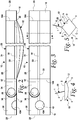
Fig. 6 is top plan view of the end portion of a roll of sheet material used for forming the package, the material being shown lying flat prior to any forming operation. -
Fig. 7 is a perspective view of the package after initial forming operations have wrapped the sheet material and formed a fin seal. -
Fig. 8 is a perspective view of the package after subsequent forming operations have folded down the fin seal and pinched and sealed the ends to form the end seals. -
Fig. 1 shows an embodiment of thepackage 10 of the present invention. The package may be formed by wrapping an elongated sheet material around a catheter or other elongated product (not shown). The wrapped sheet includes abody 12 which defines a three-dimensional cavity 14 therein for receiving the product. Thebody 12 joins afirst end seal 16 at one end and asecond end seal 18 located at the opposite end of the package. The boundaries of the first and second end seals are shown at 16a and 18a, respectively. - A
longitudinal fin 20 extends the length of the package. As will be more fully explained below, the fin may be formed by confronting side panels of the wrapped sheet material. The fin 20 is joined to thebody 12 andend seals fold line 22. The boundaries of the fin not at thefold line 22 define a free edge. In the embodiment shown the fin has both a longitudinalfree edge 24 and two endfree edges 26. While the end free edges are conveniently made to be perpendicular to the longitudinal free edge as shown, one or both of the end free edges could have a different configuration, such as a curved portion that merges with the longitudinal free edge. - Other views of the
package 10 are shown inFigs. 2-5 . At least a portion of the confronting side panels of thefin 20 are held in contact with one another and sealed at afin seal 28. In the illustrated embodiment the fin seal extends from the longitudinalfree edge 24 to a fin seal terminal line shown at 30. Thus, there is preferably anon-sealed portion 32 of the fin between theterminal line 30 and thefold line 22. It will be understood that thefin seal 28 could be located differently on thefin 20. For example, the fin seal could extend fully from thefree edge 24 to thefold line 22. Alternatively, the fin seal could extend from thefold line 22 partially toward thefree edge 24. In another alternative there could be a longitudinal hiatus in the fin seal, i.e, there could be sealed longitudinal strips both above and below a non-sealed portion. While various arrangements of the fin seal are possible, some portion of the fin must be sealed at all longitudinal points along its length. - A
pull tab 34 is formed in thefin 20 by astarter line 36 that extends to one of the free edges of the fin, in this case the longitudinalfree edge 24. The starter line as shown at 36 may be a generally semi-circular cut fully through the thickness of thefin 20 and extends to or near thefold line 22 in the area of thefirst end seal 16. Preferably the starter line will extend to a single-sealed area of the fin, as will be more fully explained below. This means the starter line will approach thefold line 22 to about 6.4 mm (about a quarter inch) from the fold line, although it could stop short of that. It may also be preferred that the last portion, that is 6.4 mm or so (e.g., a quarter inch or so), of the internal end of the starter line be directed within 15 to 20 degrees of parallel to thefold line 22, although other arrangements are possible. This will tend to direct the intentional opening tear line along thefold line 22 and finseal terminal line 30. - It will be noted that the
starter line 36 does not extend on to any portion of theend seal 16; only thefin 20 has the starter line. Furthermore, thestarter line 36 extends all the way to afree edge fin 20 to facilitate the beginning of an opening tear. While the starter line extends to a fin free edge, it does not have to be a complete cut through the full thickness of the fin. It could be an alternate form of weakening the fin to enable a tear to be started readily. For example, thestarter line 36 could be a score line only partially through the thickness of the fin, e.g., through one of the two layers of the sheet material that comprise the fin. The score line weakens the fin to enable starting of a tear but is not cut fully through the fin. Further alternate forms of the starter line may include a perforated line, or a combination of perforations, scores and cuts. In any case the starter line defines thepull tab 34 which can be engaged by a user. This allows the user to pull on the fin and use it as a tear strip that removes at least thefin seal 28 from the package and thereby opens the package. - Engagement with the
pull tab 34 can be enhanced by forming afirst finger hole 38 in the pull tab. Note that that thefirst finger hole 38 is formed entirely within thefin 20. Asecond finger hole 40 may be formed in thefirst end seal 16. Note that aportion 40a of the second finger hole extends onto thefin 20. Providing two finger holes allows the user to engage the fin with one hand and the end seal with the other hand and pull the two pieces apart, which removes thefin seal 28 from the package and lays it open for removal of the catheter. - It will be understood that
Figs. 2 - 5 show thepackage 10 somewhat diagrammatically in that the boundaries of theactual body portion 12 do not necessarily have sharply defined edges as the drawings might suggest. Because the body has a three-dimensional shape that merges to flat portions at the end seals 16, 18, the actual transition from one portion of the body to another is somewhat more gradual than implied by the drawings. - Turning now to
Fig. 6 , a representation of thesheet material 42 is shown prior to any forming steps. The sheet material may be a gas impermeable foil that may be coated with a heat seal layer. It may be a directional tear material, although other materials could be used. To assist in understanding how thesheet material 42 is folded and sealed, the sheet material is shown having longitudinal panels or areas 1 - 6 which are divided by imaginary demarcation lines A - E. The panels may be designated asside panels upper panels lower panels side panels sheet material 42 of course has top and bottom surfaces, which will become inside and outside surfaces of the package. The inside surfaces are indicated with dotted reference numerals while the outside surfaces will be shown in subsequent figures in solid reference numerals. As mentioned, all or a portion of the inside surfaces may have an adhesive coating or heat seal layer thereon. Typically this is a heat-activated adhesive that will adhere to at least other similarly coated surfaces when pressed against such surfaces and heated. Other types of adhesives could be used. - Also, while
Figs. 6 - 7 show just a single package, it will be understood that the manufacturing process described below is advantageously performed in a continuous manner. That is, an endless roll of sheet material is fed successively to a series of forming stations, (e.g., stations for wrapping, fin sealing, pinching, end sealing, punching, etc.), with individual packages not being separated from the endless roll until they have passed through all of the stations. - Package formation may begin by unrolling the sheet material into a flat, generally horizontal condition with a front or leading
edge 48 that will be fed to successive forming stations or zones. At a loading station a catheter (not shown) is placed on the inside surface of thesheet material 42, at or near the longitudinal center line C of the sheet. The sheet material, with the catheter on its inside surface, is then advanced to a wrapping station or zone wherein the sides of thesheet 42 are wrapped or folded up and around the catheter. The inside surfaces of just theside panels tubular body 12 and thefin 20 of the package. - Next the
fin 20 passes through a sealing station where rollers or the like create thefold line 22 and thefin seal 28. Typically the fin seal is created by heated rollers that activate the adhesive on portions of the inside surfaces ofside panels Fig. 7 by the cross-hatched area. This process defines the longitudinalfree edge 24 of the fin and the finseal terminal line 30. In some embodiments it may be desirable to trim the longitudinalfree edge 24 of thefin 20 to assure that the side edges ofpanels starter line 36 andfinger hole 38 during fin sealing, as explained further below. -
Fig. 7 illustrates the package at this stage of its manufacture. Note that at this stage theside panels line 22 is formed along demarcation lines A and E. Thus,panels fin 20. The cross-hatched portions of the inside surfaces ofpanels fin seal 28. The lower portions of the inside surfaces ofpanels seal terminal line 30 and foldline 22, are in confronting relation but they are not sealed to one another; they define thenon-sealed portion 32 of thefin 20. Thenon-sealed portions 32 ofpanels body 12 is or is not stretched. But in any event the non-sealed portions ofpanels - Also in
Fig. 7 note thatupper panels fold line 22 at demarcation lines A andE. Lower panels upper panels Lower panels package body 12 is formed bypanels interior cavity 14 in which the catheter resides. Again, the actual package may not have panel boundaries as sharply defined as the figures might suggest. - Once the
tubular body 12 andfin 20 have been formed, the next step in the manufacturing process is preparation for creation of the first and second end seals 16 and 18. This is done at a pinching zone where portions of the upper and lower panels of the sheet material are all placed in a generally flat condition, with the upper and lower panels confronting one another. Pinching is done only at selected, spaced locations along the sheet material, leaving intervening sections of panels 2 - 5 free to form the three-dimensional package body 12. As indicated schematically inFig. 8 , thefirst end seal 16 of aleading package 10a is formed simultaneously with the immediately-adjacentsecond end seal 18 of a successive, trailingpackage 10b. That is, both of the end seals are created at a single pinching and end sealing zone but the single sealing zone creates end seals for what will become separate packages. The leading and trailingpackages body panels panels panels fin 20 is folded down into a generally horizontal condition. Folding of the fin may be done either before, during or after the pinching operation of panels 2 - 5. - Once pinching and folding operations are complete, the sheet enters the end seal station. Here hot, transverse rollers contact the pinched portions to form the
first end seal 16 of a leading package and thesecond end seal 18 of a trailing package. The end seals 16, 18 are shown inFig. 8 by the cross-hatching that is in a different direction from that of thefin seal 28. Note that the end sealing rollers will also cross over the folded-downfin 20, resulting in: a) a double-sealed area 50 (as indicated at the double cross-hatched areas) of thefin panels fin seal 28; and b) a single-sealed area 52 (as indicated at the single cross-hatched area of the fin) of thefin panels fold line 22 and the finseal terminal line 30. Prior to forming the end seals this single-sealedarea 52 was part of the non-sealed portion of the fin. The single-sealed area of the fin is shown at 52 and exists only at the area of the end seals 16 and 18. - It is pointed out that since the outside surfaces of the
sheet panels Fig. 8 thefin 20 is folded ontoupper panel 5 but the fin will not stick to that panel. After end sealing thefin 20 is free to fold back up, out of the plane of the end seals, as shown byFig. 1 . - While the package is held taught during the end sealing operation, it is an advantageous time to perform the slitting and punching operations needed to form the
starter line 36 and thefirst finger hole 38, if this was not already done during fin seal formation. Thesecond finger hole 40 can also be formed at this time. In this regard, it will be noted that thesecond finger hole 40 can be formed by a simple punching operation that extends through both thefirst end seal 16 and the folded-downfin 20. However, formation of thestarter line 36 andfirst finger hole 38 requires a more delicate operation because these are formed only in thefin 20. That is, thestarter line 36 impacts one or both of thepanels first finger hole 38 impacts bothpanels starter line 36 orfinger hole 38. Thestarter line 36 andfinger hole 38 can be formed by laser cutting or by a vertical, mechanical punch while the material is taught and being passed through the fin sealing rollers. Preferably the starter line will extend to the single-sealedarea 52 of thefin 20. Terminating the starter line in the single-sealedarea 52 provides a good compromise between maintaining the integrity of the package seal during shipping and handling and minimizing the opening force required when it is time to open the package. - The final step in the manufacturing process is severing the finished, leading package off the front end of the sheet material. The severing action separates the
first end seal 16 of the leading package from thesecond end seal 18 of a trailing package.. It also defines the endfree edge 26 of the fin. Severing leaves afinished package 10 in the condition generally shown inFig. 1 . - The use of the package may proceed as follows. A user will engage the
package 10 in two places, the pull tab 34 (via the first finger hole 38) and the first end seal 16 (via the second finger hole 40). The user will then pull these two portions apart. As this is done thestarter line 36 will direct the initial separation or tear of the two components such that a tear line propagates toward thenon-sealed portion 32 of thefin 28. Because, at least in part, of the extra strength afforded by the double thickness of thefin seal 28, the tear line will not propagate onto or through the fin seal, but instead the tear line will propagate through the single thicknesses of either thenon-sealed portion 32, inpanels fold line 22 or the other side of thefold line 22, inpanels fin seal 28 between the end seals 16 and 18 may be removed, laying open thepackage body 12 as only non-sealed panels of the package body remain. Packages of the type described herein, with a fin seal used to tear open the package, result in a clean, straight tear. Using the fin seal for opening will also allow the package to be opened on the top and leave the opened package lying flat for easy removal of the catheter by the user. This contrasts with present packages that open the package on its side. Furthermore, a lower package opening force is required to open along the fin seal, compared to known opening features. - It should be understood that various changes and modifications to the presently preferred embodiments described herein will be apparent to those skilled in the art. Such changes and modification can be made without departing from the spirit and scope of the invention disclosed herein. For example, the arrangement of the starter line and finger holes could be other than as shown. The
starter line 36 could extend from the endfree edge 26 of the fin instead of from the longitudinalfree edge 24 as shown. This may allow moving thesecond finger hole 40 off of the fin entirely so as to not interfere with a propagating tear line upon opening. A starter line beginning at the endfree edge 26 might also benefit from deletion of the first finger hole. In this case the fin itself may serve as the pull tab. In another alternate embodiment the starter line could be formed in the fin, extending from the longitudinal free edge at a point remote from either end seal. Such a starter line could also have a first finger hole placed nearby and/or have the second finger hole placed in the fin at the nearest end seal.
Claims (10)
- A package (10), comprising:an elongated sheet having first and second side panels (1, 6), and upper and lower panels (2, 3, 4, 5), the sheet being wrapped into a shape that defines a three-dimensional cavity (14) wherein the first and second side panels (1, 6) are in confronting relation to one another to define a fin (20) having a longitudinal free edge (24) and opposed end free edges (26);at least a portion of the side panels (1, 6) parallel to the longitudinal free edge (24) of the fin (20) being adhered to one another to define a fin seal (28) extending between the longitudinal free edge (24) to a fin seal terminal line (30) which is parallel to the longitudinal free edge (24), portions of the upper and lower panels (2, 3, 4, 5) being placed in confronting relation and said portions of the upper and lower panels (2, 3, 4, 5) being adhered to one another to define first and second end seals (16, 18); anda starter line (36) formed in the fin (20) at a location between the end free edges (26), the starter line (36) extending from the longitudinal free edge (24) of the fin (20) toward the upper panels (2, 5) wherein the starter line (36) directs tearing of the package (10) along the terminal line (30).
- The package (10) of claim 1 further comprising a first finger hole (38) formed in the fin (20).
- The package (10) of claim 2 further comprising a second finger hole (40) formed in one of the end seals (16, 18).
- The package (10) of claim 1 wherein at least a portion of the side panels (1, 6) of the fin (20) are not adhered to one another to define a non-sealed portion (32) of the fin (20), and wherein one of the first and second end seals (16, 18) extends onto the non-sealed portion (32) of the fin (20) to define a single-sealed area (52) of the fin (20), the starter line (36) extending from the free edge (24) of the fin (20) to the single-sealed area (52).
- The package (10) of claim 1 wherein the fin (20) is connected to the upper panels (2, 5) at a fold line (22).
- The package (10) of claim 5 wherein the fin seal (28) extends from the free edge (24) of the fin (20) to a fin seal terminal line (30) that is spaced from the fold line (22), with the space between the fold line (22) and the fin seal terminal line (30) defining a non-sealed portion (32) of the fin (20), and wherein one of the first and second end seals (16, 18) extends onto the non-sealed portion (32) of the fin (20) to define a single-sealed area (52) of the fin (20), the starter line (36) extending from the free edge (24) of the fin (20) to the single-sealed area (52).
- The package (10) of claim 2 wherein the starter line (36) defines an arc which is concentric with the first finger hole (38).
- A method of making a package (10) for containing a catheter, comprising the steps of:a) placing a single layer of an elongated sheet material (42) in a horizontal condition, the sheet material (42) having first and second side panels (1, 6) at the longitudinal side edges (44, 46) of the sheet material (42), first and second upper panels (2, 5) adjacent the side panels (1, 6), and first and second lower panels (3, 4) adjacent the upper panels (2, 5);b) placing the catheter to be contained in the package (10) on the inside surface of the sheet material (42) at or near a longitudinal center line of the sheet material (42);c) wrapping the first and second side panels (1, 6) of the sheet material (42) around the catheter by placing the first and second side panels (1, 6) in confronting relation with one another, with the longitudinal side edges (44, 46) in or near alignment, to form a fin (20) and tubular body (12);d) sealing the confronting first and second side panels (1, 6) to one another to form a fin seal (28) having a longitudinal free edge (24) and a fin seal terminal line (30);e) placing the upper and lower panels (2, 3, 4, 5) in a generally flat condition, with the upper and lower panels (2, 3, 4, 5) confronting one another;f) pinching portions of the upper and lower panels (2, 3, 4, 5) at select locations along the sheet material (42); [[;]]g) sealing at least a portion of the confronting upper and lower panels (2, 3, 4, 5) to one another to form a first end seal (16) and a second end seal (18);h) forming a weakened starter line (36) in one or both of the side panels (1, 6) of the fin (20) starting at the longitudinal free edge (24) and extending toward the fin seal terminal line (30);i) forming a first finger hole (38) through both of the side panels (1, 6) of the fin (20).
- The method of Claim 8 further comprising forming a second finger hole (40) extending through both the first end seal (16) and said fin (20).
- The method of any one of Claims 8 through 9 wherein said starter line (36) defines an arc which is concentric with said first finger hole (38) in said fin (20).
Priority Applications (2)
| Application Number | Priority Date | Filing Date | Title |
|---|---|---|---|
| EP20156911.8A EP3666321B1 (en) | 2014-01-09 | 2015-01-08 | Package having integral tab with finger hole opening feature |
| DK20156911.8T DK3666321T3 (en) | 2014-01-09 | 2015-01-08 | PACK WITH INTEGRATED FLAP WITH FINGER HOLE OPENING FUNCTION |
Applications Claiming Priority (2)
| Application Number | Priority Date | Filing Date | Title |
|---|---|---|---|
| US201461925463P | 2014-01-09 | 2014-01-09 | |
| PCT/US2015/010645 WO2015105990A1 (en) | 2014-01-09 | 2015-01-08 | Package having integral tab with finger hole opening feature |
Related Child Applications (2)
| Application Number | Title | Priority Date | Filing Date |
|---|---|---|---|
| EP20156911.8A Division EP3666321B1 (en) | 2014-01-09 | 2015-01-08 | Package having integral tab with finger hole opening feature |
| EP20156911.8A Division-Into EP3666321B1 (en) | 2014-01-09 | 2015-01-08 | Package having integral tab with finger hole opening feature |
Publications (2)
| Publication Number | Publication Date |
|---|---|
| EP3092025A1 EP3092025A1 (en) | 2016-11-16 |
| EP3092025B1 true EP3092025B1 (en) | 2020-03-18 |
Family
ID=52434969
Family Applications (2)
| Application Number | Title | Priority Date | Filing Date |
|---|---|---|---|
| EP15701868.0A Active EP3092025B1 (en) | 2014-01-09 | 2015-01-08 | Package having integral tab with finger hole opening feature |
| EP20156911.8A Active EP3666321B1 (en) | 2014-01-09 | 2015-01-08 | Package having integral tab with finger hole opening feature |
Family Applications After (1)
| Application Number | Title | Priority Date | Filing Date |
|---|---|---|---|
| EP20156911.8A Active EP3666321B1 (en) | 2014-01-09 | 2015-01-08 | Package having integral tab with finger hole opening feature |
Country Status (9)
| Country | Link |
|---|---|
| US (1) | US10112761B2 (en) |
| EP (2) | EP3092025B1 (en) |
| AU (1) | AU2015204761B2 (en) |
| CA (1) | CA2936317C (en) |
| DK (2) | DK3666321T3 (en) |
| ES (2) | ES2929311T3 (en) |
| HU (2) | HUE060357T2 (en) |
| LT (2) | LT3092025T (en) |
| WO (1) | WO2015105990A1 (en) |
Cited By (2)
| Publication number | Priority date | Publication date | Assignee | Title |
|---|---|---|---|---|
| US10874541B2 (en) | 2017-11-09 | 2020-12-29 | 11 Health And Technologies Limited | Ostomy monitoring system and method |
| USD935477S1 (en) | 2018-11-08 | 2021-11-09 | 11 Health And Technologies Limited | Display screen or portion thereof with graphical user interface |
Families Citing this family (8)
| Publication number | Priority date | Publication date | Assignee | Title |
|---|---|---|---|---|
| MX348673B (en) | 2008-05-01 | 2017-06-23 | Convatec Tech Inc * | Rectal drain appliance. |
| EP2686031B1 (en) | 2011-03-17 | 2020-02-12 | ConvaTec Technologies Inc. | High barrier elastomer fecal catheter of ostomy pouch |
| CA2918607C (en) | 2013-08-01 | 2024-02-20 | Convatec Technologies Inc. | Self-closing bag connector |
| LT3634561T (en) | 2017-06-09 | 2024-03-25 | Hollister Incorporated | Packages for medical devices |
| GB201721956D0 (en) | 2017-12-27 | 2018-02-07 | Convatec Ltd | Female catheter locator tip |
| GB201721955D0 (en) | 2017-12-27 | 2018-02-07 | Convatec Ltd | Catheter wetting devices |
| AU2019384142A1 (en) | 2018-11-21 | 2021-06-17 | Hollister Incorporated | Medical device package |
| JP2022536671A (en) | 2019-06-11 | 2022-08-18 | コンバテック・テクノロジーズ・インコーポレイテッド | Urine collection bag for use with catheter products and method of making urine collection bag |
Citations (1)
| Publication number | Priority date | Publication date | Assignee | Title |
|---|---|---|---|---|
| WO2008029106A1 (en) * | 2006-09-04 | 2008-03-13 | Cadbury Holdings Limited | Improved packaging with lines of weakness |
Family Cites Families (42)
| Publication number | Priority date | Publication date | Assignee | Title |
|---|---|---|---|---|
| US3291377A (en) | 1966-02-07 | 1966-12-13 | Nat Dairy Prod Corp | Packaging |
| US3286832A (en) | 1966-03-30 | 1966-11-22 | Reynolds Metals Co | Sterile article package |
| US3411620A (en) | 1967-05-15 | 1968-11-19 | Kendall & Co | Combination catheter tray and package |
| NL7308697A (en) * | 1972-06-28 | 1974-01-02 | ||
| DE2458462C2 (en) | 1974-12-10 | 1993-02-11 | Fa. Alfred Ritter, 7035 Waldenbuch | Tubular bag packaging, in particular for chocolate bars |
| DE2613299A1 (en) * | 1976-03-29 | 1977-10-20 | Weltin Optac | PACKAGING FOR A HEARING PLUG |
| AT380666B (en) | 1980-04-16 | 1986-06-25 | Sticht Walter | PACKING FILM, ESPECIALLY FOR FOODSTUFFS |
| CH651795A5 (en) * | 1981-08-06 | 1985-10-15 | Sig Schweiz Industrieges | Pack for piece goods, process for producing the pack and tubular-bag machine for carrying out the process |
| US4658963A (en) | 1984-04-20 | 1987-04-21 | Folienwalzwerk Bruder Teich Aktiengesellschaft | Package with weakened portion for opening |
| DE3618765A1 (en) * | 1986-06-04 | 1987-12-10 | Scheuch Folien Papier Kg | Tubular bag package for slab-shaped or bar-shaped products, for example chocolate products |
| GB8704531D0 (en) | 1987-02-26 | 1987-04-01 | Bard Ltd | Catheter introducer |
| US4834245A (en) * | 1988-08-05 | 1989-05-30 | Kabushiki Kaisha Hosokawa Yoko | Pouch having tearing zone for taking out content packed therein |
| US4966286A (en) * | 1989-06-26 | 1990-10-30 | The Procter & Gamble Company | Easy open flexible bag |
| US5366295A (en) | 1990-08-13 | 1994-11-22 | Nestec S.A. | Flexible easy-opening pack |
| DE4107380A1 (en) * | 1991-03-08 | 1992-09-10 | Lohmann Gmbh & Co Kg | HOSE BAG PACKING, ESPECIALLY FOR BINDING-LIKE GOODS |
| DE4109605A1 (en) | 1991-03-23 | 1992-09-24 | Lohmann Gmbh & Co Kg | TUBE PACKAGING |
| US5229180A (en) | 1991-10-02 | 1993-07-20 | American National Can Company | Laser scored package |
| US5885673A (en) * | 1993-07-30 | 1999-03-23 | Eastman Kodak Company | Peelable pouch-like packaging for photographic sheet film |
| IT1273179B (en) | 1994-05-05 | 1997-07-07 | Sales Spa | OPENING DEVICE FOR FLEXIBLE CONTAINERS, CONTAINER PROVIDED WITH SUCH DEVICE AND PROCEDURE FOR ITS APPLICATION |
| IL116949A0 (en) | 1995-02-01 | 1996-05-14 | Mcneil Ppc Inc | A flexible tubular package |
| AU4062197A (en) | 1996-08-14 | 1998-03-06 | Medical Marketing Group, Inc. | Prelubricated urinary catheter and package assembly |
| ES2270604T3 (en) | 1998-06-25 | 2007-04-01 | C.R. Bard, Inc. | MEDICAL DEVICE WITH ELASTOMERO BALL. |
| DE29907206U1 (en) * | 1999-04-26 | 1999-07-15 | Hassia Verpackung Ag | Tubular bag pack, in particular so-called cross-stitch pack |
| WO2001052763A1 (en) * | 2000-01-19 | 2001-07-26 | Medical Technologies Of Georgia, Inc. | Catheter package and method |
| FR2829117B1 (en) | 2001-09-06 | 2004-09-10 | Bel Fromageries | PACKAGING DEVICE FOR CONTAINING AT LEAST TWO PRODUCTS, AND ASSEMBLY FORMED BY SAID DEVICE AND PRODUCTS |
| US20040252920A1 (en) * | 2001-10-26 | 2004-12-16 | Yoshiji Moteki | Packaging member with easy-opening means |
| ES2285089T3 (en) | 2002-01-28 | 2007-11-16 | Coloplast A/S | EASY TO OPEN PACKING. |
| DE60309440T2 (en) * | 2002-02-08 | 2007-10-11 | The Procter & Gamble Company, Cincinnati | CHILD-SAFE PACKAGING |
| US6889483B2 (en) | 2002-10-31 | 2005-05-10 | Cryovac, Inc. | Easy-opening feature for flexible packages and process and apparatus for forming same |
| US7862869B2 (en) | 2003-10-20 | 2011-01-04 | Milprint, Inc. | Tear initiation and directional tear films and packages made therefrom |
| JP2009528106A (en) | 2006-03-01 | 2009-08-06 | コロプラスト アクティーゼルスカブ | Urine sheath with molded deployment band |
| ES2426272T3 (en) | 2006-06-08 | 2013-10-22 | Hollister Incorporated | Catheter product container |
| DE202007002960U1 (en) * | 2007-02-28 | 2007-09-13 | Sca Hygiene Products Gmbh | Packaging for hygiene products |
| MX2010000589A (en) | 2007-07-16 | 2010-07-29 | Bard Inc C R | Foley catheter having sterile barrier. |
| DE102009000331A1 (en) | 2009-01-20 | 2010-07-22 | Robert Bosch Gmbh | Tubular bag packaging for tabular general cargo |
| DE102010004440B3 (en) * | 2009-04-23 | 2010-12-16 | Manfred Haiss | Tubular bag packaging and method for its production |
| JP5606784B2 (en) * | 2010-05-13 | 2014-10-15 | ユニ・チャーム株式会社 | Package for individual packaged absorbent articles |
| CA2799794A1 (en) | 2010-05-18 | 2011-11-24 | Kraft Foods Global Brands Llc | Easy open flexible film packaging products and methods of manufacture |
| ES2539374T3 (en) | 2011-01-28 | 2015-06-30 | Unilever N.V. | Bag with laser perforations |
| EP2484603B1 (en) * | 2011-02-04 | 2013-12-18 | Mondi AG | Film and packaging made from it with opening aid |
| WO2014085085A1 (en) * | 2012-11-30 | 2014-06-05 | The Procter & Gamble Company | Easy opening bag |
| US20160176601A1 (en) * | 2014-12-19 | 2016-06-23 | The Quaker Oats Company | Easy-open flexible package |
-
2015
- 2015-01-08 CA CA2936317A patent/CA2936317C/en active Active
- 2015-01-08 EP EP15701868.0A patent/EP3092025B1/en active Active
- 2015-01-08 DK DK20156911.8T patent/DK3666321T3/en active
- 2015-01-08 WO PCT/US2015/010645 patent/WO2015105990A1/en active Application Filing
- 2015-01-08 AU AU2015204761A patent/AU2015204761B2/en active Active
- 2015-01-08 LT LTEP15701868.0T patent/LT3092025T/en unknown
- 2015-01-08 LT LTEP20156911.8T patent/LT3666321T/en unknown
- 2015-01-08 ES ES20156911T patent/ES2929311T3/en active Active
- 2015-01-08 HU HUE20156911A patent/HUE060357T2/en unknown
- 2015-01-08 HU HUE15701868A patent/HUE050746T2/en unknown
- 2015-01-08 ES ES15701868T patent/ES2791284T3/en active Active
- 2015-01-08 US US15/110,698 patent/US10112761B2/en active Active
- 2015-01-08 EP EP20156911.8A patent/EP3666321B1/en active Active
- 2015-01-08 DK DK15701868.0T patent/DK3092025T3/en active
Patent Citations (1)
| Publication number | Priority date | Publication date | Assignee | Title |
|---|---|---|---|---|
| WO2008029106A1 (en) * | 2006-09-04 | 2008-03-13 | Cadbury Holdings Limited | Improved packaging with lines of weakness |
Cited By (3)
| Publication number | Priority date | Publication date | Assignee | Title |
|---|---|---|---|---|
| US10874541B2 (en) | 2017-11-09 | 2020-12-29 | 11 Health And Technologies Limited | Ostomy monitoring system and method |
| US11406525B2 (en) | 2017-11-09 | 2022-08-09 | 11 Health And Technologies Limited | Ostomy monitoring system and method |
| USD935477S1 (en) | 2018-11-08 | 2021-11-09 | 11 Health And Technologies Limited | Display screen or portion thereof with graphical user interface |
Also Published As
| Publication number | Publication date |
|---|---|
| WO2015105990A1 (en) | 2015-07-16 |
| US20160325903A1 (en) | 2016-11-10 |
| EP3666321B1 (en) | 2022-08-17 |
| AU2015204761A1 (en) | 2016-07-28 |
| DK3092025T3 (en) | 2020-05-18 |
| LT3666321T (en) | 2022-09-12 |
| HUE060357T2 (en) | 2023-02-28 |
| ES2791284T3 (en) | 2020-11-03 |
| LT3092025T (en) | 2020-07-10 |
| DK3666321T3 (en) | 2022-10-17 |
| EP3092025A1 (en) | 2016-11-16 |
| ES2929311T3 (en) | 2022-11-28 |
| HUE050746T2 (en) | 2021-01-28 |
| US10112761B2 (en) | 2018-10-30 |
| EP3666321A1 (en) | 2020-06-17 |
| CA2936317C (en) | 2020-04-21 |
| CA2936317A1 (en) | 2015-07-16 |
| AU2015204761B2 (en) | 2019-06-06 |
Similar Documents
| Publication | Publication Date | Title |
|---|---|---|
| EP3092025B1 (en) | Package having integral tab with finger hole opening feature | |
| US20210370018A1 (en) | Medical device package | |
| US9994374B2 (en) | Packaging | |
| CN105026285B (en) | Pack access opening feature structure and its manufacture method | |
| US9656783B2 (en) | Reclosable flexible packaging and methods for manufacturing same | |
| US6889483B2 (en) | Easy-opening feature for flexible packages and process and apparatus for forming same | |
| US20080152264A1 (en) | Flexible easy-open package with reclosable feature | |
| EP2709910B1 (en) | Reclosable flexible packaging, laminate and method for manufacturing same | |
| EP3774325A1 (en) | Laminated material and process for its manufacture, as well as sheet and container obtained from this laminated material | |
| EP3515836B1 (en) | Packaging film with top layer forming a predefined opening track | |
| CN108367541B (en) | Sealing foil with pull tab | |
| JP6326201B2 (en) | Package | |
| NZ741858B2 (en) | Sealing foil with pull tab | |
| JP2015139372A (en) | Packaging material with label for food | |
| AU2015200080A1 (en) | Flexible laminated packaging with peelable adhesive |
Legal Events
| Date | Code | Title | Description |
|---|---|---|---|
| PUAI | Public reference made under article 153(3) epc to a published international application that has entered the european phase |
Free format text: ORIGINAL CODE: 0009012 |
|
| 17P | Request for examination filed |
Effective date: 20160805 |
|
| AK | Designated contracting states |
Kind code of ref document: A1 Designated state(s): AL AT BE BG CH CY CZ DE DK EE ES FI FR GB GR HR HU IE IS IT LI LT LU LV MC MK MT NL NO PL PT RO RS SE SI SK SM TR |
|
| AX | Request for extension of the european patent |
Extension state: BA ME |
|
| DAX | Request for extension of the european patent (deleted) | ||
| STAA | Information on the status of an ep patent application or granted ep patent |
Free format text: STATUS: EXAMINATION IS IN PROGRESS |
|
| 17Q | First examination report despatched |
Effective date: 20190121 |
|
| GRAP | Despatch of communication of intention to grant a patent |
Free format text: ORIGINAL CODE: EPIDOSNIGR1 |
|
| STAA | Information on the status of an ep patent application or granted ep patent |
Free format text: STATUS: GRANT OF PATENT IS INTENDED |
|
| INTG | Intention to grant announced |
Effective date: 20191209 |
|
| GRAS | Grant fee paid |
Free format text: ORIGINAL CODE: EPIDOSNIGR3 |
|
| GRAA | (expected) grant |
Free format text: ORIGINAL CODE: 0009210 |
|
| STAA | Information on the status of an ep patent application or granted ep patent |
Free format text: STATUS: THE PATENT HAS BEEN GRANTED |
|
| AK | Designated contracting states |
Kind code of ref document: B1 Designated state(s): AL AT BE BG CH CY CZ DE DK EE ES FI FR GB GR HR HU IE IS IT LI LT LU LV MC MK MT NL NO PL PT RO RS SE SI SK SM TR |
|
| REG | Reference to a national code |
Ref country code: GB Ref legal event code: FG4D |
|
| REG | Reference to a national code |
Ref country code: AT Ref legal event code: REF Ref document number: 1245213 Country of ref document: AT Kind code of ref document: T Effective date: 20200415 Ref country code: NL Ref legal event code: FP Ref country code: IE Ref legal event code: FG4D |
|
| REG | Reference to a national code |
Ref country code: DE Ref legal event code: R096 Ref document number: 602015048940 Country of ref document: DE |
|
| REG | Reference to a national code |
Ref country code: DK Ref legal event code: T3 Effective date: 20200513 |
|
| REG | Reference to a national code |
Ref country code: SE Ref legal event code: TRGR |
|
| PG25 | Lapsed in a contracting state [announced via postgrant information from national office to epo] |
Ref country code: RS Free format text: LAPSE BECAUSE OF FAILURE TO SUBMIT A TRANSLATION OF THE DESCRIPTION OR TO PAY THE FEE WITHIN THE PRESCRIBED TIME-LIMIT Effective date: 20200318 Ref country code: NO Free format text: LAPSE BECAUSE OF FAILURE TO SUBMIT A TRANSLATION OF THE DESCRIPTION OR TO PAY THE FEE WITHIN THE PRESCRIBED TIME-LIMIT Effective date: 20200618 Ref country code: FI Free format text: LAPSE BECAUSE OF FAILURE TO SUBMIT A TRANSLATION OF THE DESCRIPTION OR TO PAY THE FEE WITHIN THE PRESCRIBED TIME-LIMIT Effective date: 20200318 |
|
| PG25 | Lapsed in a contracting state [announced via postgrant information from national office to epo] |
Ref country code: BG Free format text: LAPSE BECAUSE OF FAILURE TO SUBMIT A TRANSLATION OF THE DESCRIPTION OR TO PAY THE FEE WITHIN THE PRESCRIBED TIME-LIMIT Effective date: 20200618 Ref country code: GR Free format text: LAPSE BECAUSE OF FAILURE TO SUBMIT A TRANSLATION OF THE DESCRIPTION OR TO PAY THE FEE WITHIN THE PRESCRIBED TIME-LIMIT Effective date: 20200619 Ref country code: HR Free format text: LAPSE BECAUSE OF FAILURE TO SUBMIT A TRANSLATION OF THE DESCRIPTION OR TO PAY THE FEE WITHIN THE PRESCRIBED TIME-LIMIT Effective date: 20200318 Ref country code: LV Free format text: LAPSE BECAUSE OF FAILURE TO SUBMIT A TRANSLATION OF THE DESCRIPTION OR TO PAY THE FEE WITHIN THE PRESCRIBED TIME-LIMIT Effective date: 20200318 |
|
| PG25 | Lapsed in a contracting state [announced via postgrant information from national office to epo] |
Ref country code: SK Free format text: LAPSE BECAUSE OF FAILURE TO SUBMIT A TRANSLATION OF THE DESCRIPTION OR TO PAY THE FEE WITHIN THE PRESCRIBED TIME-LIMIT Effective date: 20200318 Ref country code: IS Free format text: LAPSE BECAUSE OF FAILURE TO SUBMIT A TRANSLATION OF THE DESCRIPTION OR TO PAY THE FEE WITHIN THE PRESCRIBED TIME-LIMIT Effective date: 20200718 Ref country code: CZ Free format text: LAPSE BECAUSE OF FAILURE TO SUBMIT A TRANSLATION OF THE DESCRIPTION OR TO PAY THE FEE WITHIN THE PRESCRIBED TIME-LIMIT Effective date: 20200318 Ref country code: RO Free format text: LAPSE BECAUSE OF FAILURE TO SUBMIT A TRANSLATION OF THE DESCRIPTION OR TO PAY THE FEE WITHIN THE PRESCRIBED TIME-LIMIT Effective date: 20200318 Ref country code: PT Free format text: LAPSE BECAUSE OF FAILURE TO SUBMIT A TRANSLATION OF THE DESCRIPTION OR TO PAY THE FEE WITHIN THE PRESCRIBED TIME-LIMIT Effective date: 20200812 Ref country code: SM Free format text: LAPSE BECAUSE OF FAILURE TO SUBMIT A TRANSLATION OF THE DESCRIPTION OR TO PAY THE FEE WITHIN THE PRESCRIBED TIME-LIMIT Effective date: 20200318 Ref country code: EE Free format text: LAPSE BECAUSE OF FAILURE TO SUBMIT A TRANSLATION OF THE DESCRIPTION OR TO PAY THE FEE WITHIN THE PRESCRIBED TIME-LIMIT Effective date: 20200318 |
|
| REG | Reference to a national code |
Ref country code: ES Ref legal event code: FG2A Ref document number: 2791284 Country of ref document: ES Kind code of ref document: T3 Effective date: 20201103 |
|
| REG | Reference to a national code |
Ref country code: AT Ref legal event code: MK05 Ref document number: 1245213 Country of ref document: AT Kind code of ref document: T Effective date: 20200318 |
|
| REG | Reference to a national code |
Ref country code: DE Ref legal event code: R097 Ref document number: 602015048940 Country of ref document: DE |
|
| PLBE | No opposition filed within time limit |
Free format text: ORIGINAL CODE: 0009261 |
|
| STAA | Information on the status of an ep patent application or granted ep patent |
Free format text: STATUS: NO OPPOSITION FILED WITHIN TIME LIMIT |
|
| REG | Reference to a national code |
Ref country code: HU Ref legal event code: AG4A Ref document number: E050746 Country of ref document: HU |
|
| PG25 | Lapsed in a contracting state [announced via postgrant information from national office to epo] |
Ref country code: AT Free format text: LAPSE BECAUSE OF FAILURE TO SUBMIT A TRANSLATION OF THE DESCRIPTION OR TO PAY THE FEE WITHIN THE PRESCRIBED TIME-LIMIT Effective date: 20200318 |
|
| 26N | No opposition filed |
Effective date: 20201221 |
|
| PG25 | Lapsed in a contracting state [announced via postgrant information from national office to epo] |
Ref country code: PL Free format text: LAPSE BECAUSE OF FAILURE TO SUBMIT A TRANSLATION OF THE DESCRIPTION OR TO PAY THE FEE WITHIN THE PRESCRIBED TIME-LIMIT Effective date: 20200318 |
|
| PG25 | Lapsed in a contracting state [announced via postgrant information from national office to epo] |
Ref country code: SI Free format text: LAPSE BECAUSE OF FAILURE TO SUBMIT A TRANSLATION OF THE DESCRIPTION OR TO PAY THE FEE WITHIN THE PRESCRIBED TIME-LIMIT Effective date: 20200318 |
|
| PG25 | Lapsed in a contracting state [announced via postgrant information from national office to epo] |
Ref country code: MC Free format text: LAPSE BECAUSE OF FAILURE TO SUBMIT A TRANSLATION OF THE DESCRIPTION OR TO PAY THE FEE WITHIN THE PRESCRIBED TIME-LIMIT Effective date: 20200318 |
|
| REG | Reference to a national code |
Ref country code: CH Ref legal event code: PL |
|
| PG25 | Lapsed in a contracting state [announced via postgrant information from national office to epo] |
Ref country code: LU Free format text: LAPSE BECAUSE OF NON-PAYMENT OF DUE FEES Effective date: 20210108 |
|
| REG | Reference to a national code |
Ref country code: BE Ref legal event code: MM Effective date: 20210131 |
|
| PG25 | Lapsed in a contracting state [announced via postgrant information from national office to epo] |
Ref country code: LI Free format text: LAPSE BECAUSE OF NON-PAYMENT OF DUE FEES Effective date: 20210131 Ref country code: CH Free format text: LAPSE BECAUSE OF NON-PAYMENT OF DUE FEES Effective date: 20210131 |
|
| PG25 | Lapsed in a contracting state [announced via postgrant information from national office to epo] |
Ref country code: BE Free format text: LAPSE BECAUSE OF NON-PAYMENT OF DUE FEES Effective date: 20210131 |
|
| PGFP | Annual fee paid to national office [announced via postgrant information from national office to epo] |
Ref country code: IE Payment date: 20230127 Year of fee payment: 9 Ref country code: FR Payment date: 20230125 Year of fee payment: 9 Ref country code: ES Payment date: 20230201 Year of fee payment: 9 Ref country code: DK Payment date: 20230127 Year of fee payment: 9 |
|
| PGFP | Annual fee paid to national office [announced via postgrant information from national office to epo] |
Ref country code: SE Payment date: 20230127 Year of fee payment: 9 Ref country code: IT Payment date: 20230120 Year of fee payment: 9 Ref country code: HU Payment date: 20221218 Year of fee payment: 9 Ref country code: GB Payment date: 20230127 Year of fee payment: 9 Ref country code: DE Payment date: 20230127 Year of fee payment: 9 |
|
| P01 | Opt-out of the competence of the unified patent court (upc) registered |
Effective date: 20230520 |
|
| PG25 | Lapsed in a contracting state [announced via postgrant information from national office to epo] |
Ref country code: CY Free format text: LAPSE BECAUSE OF FAILURE TO SUBMIT A TRANSLATION OF THE DESCRIPTION OR TO PAY THE FEE WITHIN THE PRESCRIBED TIME-LIMIT Effective date: 20200318 |
|
| PGFP | Annual fee paid to national office [announced via postgrant information from national office to epo] |
Ref country code: LT Payment date: 20231219 Year of fee payment: 10 |
|
| PGFP | Annual fee paid to national office [announced via postgrant information from national office to epo] |
Ref country code: NL Payment date: 20240126 Year of fee payment: 10 |
|
| PGFP | Annual fee paid to national office [announced via postgrant information from national office to epo] |
Ref country code: ES Payment date: 20240201 Year of fee payment: 10 Ref country code: IE Payment date: 20240129 Year of fee payment: 10 |
|
| PG25 | Lapsed in a contracting state [announced via postgrant information from national office to epo] |
Ref country code: MK Free format text: LAPSE BECAUSE OF FAILURE TO SUBMIT A TRANSLATION OF THE DESCRIPTION OR TO PAY THE FEE WITHIN THE PRESCRIBED TIME-LIMIT Effective date: 20200318 |
|
| PGFP | Annual fee paid to national office [announced via postgrant information from national office to epo] |
Ref country code: HU Payment date: 20231222 Year of fee payment: 10 Ref country code: DE Payment date: 20240129 Year of fee payment: 10 Ref country code: GB Payment date: 20240129 Year of fee payment: 10 |