EP3091898B1 - Active low impedance electrode - Google Patents
Active low impedance electrode Download PDFInfo
- Publication number
- EP3091898B1 EP3091898B1 EP15703315.0A EP15703315A EP3091898B1 EP 3091898 B1 EP3091898 B1 EP 3091898B1 EP 15703315 A EP15703315 A EP 15703315A EP 3091898 B1 EP3091898 B1 EP 3091898B1
- Authority
- EP
- European Patent Office
- Prior art keywords
- voltage
- electrode
- patient
- electrical activity
- node
- Prior art date
- Legal status (The legal status is an assumption and is not a legal conclusion. Google has not performed a legal analysis and makes no representation as to the accuracy of the status listed.)
- Active
Links
- 230000000694 effects Effects 0.000 claims description 36
- 210000003484 anatomy Anatomy 0.000 claims description 21
- 230000008878 coupling Effects 0.000 description 9
- 238000010168 coupling process Methods 0.000 description 9
- 238000005859 coupling reaction Methods 0.000 description 9
- 238000000034 method Methods 0.000 description 4
- 210000000056 organ Anatomy 0.000 description 4
- 210000004556 brain Anatomy 0.000 description 3
- 238000010586 diagram Methods 0.000 description 3
- 238000005259 measurement Methods 0.000 description 3
- 230000008901 benefit Effects 0.000 description 2
- 238000012544 monitoring process Methods 0.000 description 2
- 230000004044 response Effects 0.000 description 2
- 210000000115 thoracic cavity Anatomy 0.000 description 2
- HCHKCACWOHOZIP-UHFFFAOYSA-N Zinc Chemical compound [Zn] HCHKCACWOHOZIP-UHFFFAOYSA-N 0.000 description 1
- 239000000853 adhesive Substances 0.000 description 1
- 230000001070 adhesive effect Effects 0.000 description 1
- 230000008859 change Effects 0.000 description 1
- 230000008030 elimination Effects 0.000 description 1
- 238000003379 elimination reaction Methods 0.000 description 1
- 239000006260 foam Substances 0.000 description 1
- 238000002847 impedance measurement Methods 0.000 description 1
- 230000006872 improvement Effects 0.000 description 1
- 230000007246 mechanism Effects 0.000 description 1
- 238000012806 monitoring device Methods 0.000 description 1
- 238000004806 packaging method and process Methods 0.000 description 1
- 230000009467 reduction Effects 0.000 description 1
- 238000001228 spectrum Methods 0.000 description 1
- 239000011701 zinc Substances 0.000 description 1
- 229910052725 zinc Inorganic materials 0.000 description 1
Images

Classifications
-
- A—HUMAN NECESSITIES
- A61—MEDICAL OR VETERINARY SCIENCE; HYGIENE
- A61B—DIAGNOSIS; SURGERY; IDENTIFICATION
- A61B5/00—Measuring for diagnostic purposes; Identification of persons
- A61B5/24—Detecting, measuring or recording bioelectric or biomagnetic signals of the body or parts thereof
- A61B5/25—Bioelectric electrodes therefor
- A61B5/279—Bioelectric electrodes therefor specially adapted for particular uses
- A61B5/291—Bioelectric electrodes therefor specially adapted for particular uses for electroencephalography [EEG]
-
- A—HUMAN NECESSITIES
- A61—MEDICAL OR VETERINARY SCIENCE; HYGIENE
- A61B—DIAGNOSIS; SURGERY; IDENTIFICATION
- A61B5/00—Measuring for diagnostic purposes; Identification of persons
- A61B5/24—Detecting, measuring or recording bioelectric or biomagnetic signals of the body or parts thereof
- A61B5/30—Input circuits therefor
-
- A—HUMAN NECESSITIES
- A61—MEDICAL OR VETERINARY SCIENCE; HYGIENE
- A61B—DIAGNOSIS; SURGERY; IDENTIFICATION
- A61B5/00—Measuring for diagnostic purposes; Identification of persons
- A61B5/72—Signal processing specially adapted for physiological signals or for diagnostic purposes
- A61B5/7203—Signal processing specially adapted for physiological signals or for diagnostic purposes for noise prevention, reduction or removal
Definitions
- the present invention generally relates to electrodes utilized by an electrical activity monitor for recording electrical activity of a biological organ (e.g., an electrocardiogram (“ECG”) monitor for recording electrical activity of a patient's heart and an electroencephalogram (“EEG”) monitor for recording electrical activity of a patient's brain).
- ECG electrocardiogram
- EEG electroencephalogram
- the present invention specifically relates to electrodes actively providing a low contact impedance for the ECG/EEG patient.
- ECG/EEG systems measure the voltages on a skin surface of a patient. These measured voltages are typically less than 1mV.
- a skin electrode interface impedance may vary dramatically from patient to patient. For example, these impedances may vary between 10K ohms and 10M ohms for a typical connection to the patient with standard electrodes. Such high impedances however are problematic with the use of standard electrodes.
- any electrostatic coupling into a wire that connects the electrode to an amplifier input of a ECG/EEG monitor will result in current flow across the patient impedance, and any artifact signal generated by such an electrostatic coupling is directly proportional to the impedance of the electrode skin interface.
- ECG/EEG monitors currently use shielded wires in order to minimize any electrostatic coupling.
- ECG/EEG monitors use one electrode as a reference electrode to provide for current flow between the patient and the ECG/EEG monitors.
- an active feedback loop is used to force most of the common mode current to flow through the reference electrode and minimize a common mode signal present on the measurement electrodes.
- the amplitude of the common mode signal is equal to current of the common mode coupling times the reference electrode impedance divided by the loop gain of the active feedback loop. The remaining signal then is cancelled by the matching of the input amplifiers in the input circuitry of the ECG/EEG monitors.
- sources of electrostatic coupling may be substantial for a patient being closely monitored for EEG.
- EP 2294979 A1 discloses a method and device for continuously and simultaneously measuring an impedance signal and a biopotential signal on a biological subject's skin.
- the method comprises the steps of: attaching input and output electrodes to the biological subject's skin; applying a predetermined alternating current having a first frequency to the output electrodes for creating an alternating voltage signal over the input electrodes, the first frequency being above a predetermined minimum frequency; measuring an input signal from the input electrodes, the input signal comprising a biopotential signal and the alternating voltage signal; extracting from said input signal the biopotential signal; extracting from said input signal the alternating voltage signal and determining the impedance signal from the alternating voltage signal.
- the alternating voltage signal is extracted by amplifying and demodulating the input signal using a control signal having a frequency equal to the first frequency of the applied alternating current.
- US 2003/006782 A1 discloses a method and system for measuring bioelectric impedance in the presence of interference.
- US 2011/295096 A1 discloses a method and system for electrode impedance measurement.
- the present invention provides an electrode for actively reducing the skin electrode contact impedance to thereby minimize the effects of any electrostatic coupled signals on the ECG/EEG waveform. This substantially improves the quality of the ECG/EEG measurement, especially in presence of substantial electrostatic sources (e.g., a case of patient transport). With low electrode source impedance, a shielding of ECG/EEG cabling is not necessary, and an elimination of the shielding for the ECG/EEG cables consequently allows for low cost disposable ECG/EEG cables.
- One form of the present invention is an active low impedance electrode as defined in claim 1
- exemplary embodiments of the present invention will be provided herein directed to an electrical activity monitoring of a biological organ of a patient via an active low impedance electrode connecting an anatomical region of the patient to the electrical activity monitor.
- FIG. 1 illustrates a known ECG monitor 30 recording electrical activity 31 of a heart 11 of a patient 10 via an active low impedance electrode 20a of the present invention connecting a thoracic region of patient 10 to ECG monitor 30.
- FIG. 1 illustrates known EEG monitor 40 recording electrical activity 41 of a brain 12 of a patient 10 via an active low impedance electrode 20b of the present invention connecting a cranial region of patient 10 to EEG monitor 40.
- one or more active low impedance electrodes 20 of the present invention are employed in practice for a recording of electrical activity within an anatomical region as would be appreciated by one skilled in the art, and one or more conventional electrodes may be additionally employed in practice for the recording of electrical activity within the anatomical region as would be appreciated by one skilled in the art.
- an active low impedance electrode 20 of the present invention employs an electrical activity sensor 21, a voltage sense contact 22, a current flow contact 23 and an active electrode coupler 24.
- voltage sense contact 22 and current flow contact 23 are attached as known in the art to an anatomical region 13 of patient 10 (e.g., the cranial region or the thoracic region of FIG. 1 ), and active electrode coupler 24 is connected as known in the art to an electrical activity monitor 50 (e.g., ECG monitor 30 or EEG monitor 40 of FIG. 1 ).
- Voltage sense contact 22 applies a patient voltage V P on a skin surface of anatomical region 13 to a voltage node N V of electrical activity sensor 21 having a high input impedance that effectively impedes any current flow from anatomical region 13 into voltage sense contact 22.
- fluctuation(s) of patient voltage V P are indicative of electrical activity of a biological organ within anatomical region 13 (e.g., heart 11 or brain 12 of FIG. 1 ).
- Current flow contact 23 controls a directional flow of a sensor current I S between electrical anatomical region 13 and a current node N C of electrical activity sensor 21 having a low source impedance that effectively directs any current flow from anatomical region 13 through current flow contact 22.
- the aforementioned attachment of voltage sense contract 22 and current flow contact 23 to anatomical region 13 flow sensor current I S equaling a voltage drop between voltage sense contact 22 and current flow contact 23 divided by a patient contact impedance Z PC . This facilitates a sensing of patient voltage V P by electrical activity sensor 21, particularly in a presence of a substantial flow of sensor current I S into anatomical region 13.
- Active electrode coupler 24 applies a sensor voltage V S at a power node N P of electrical activity sensor 21 to electrical activity monitor 50.
- Sensor voltage V S is representative of patient voltage V P whereby electrical activity monitor 50 may measure and record the electrical activity of the biological organ within anatomical region 13.
- an impedance Z AE of active electrode coupler 24 is significantly less (>>) than patient contact impedance Z PC .
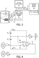
- FIG. 3 A block diagram of an exemplary embodiment of electrical activity sensor 21 is shown in block diagram shown in FIG. 3 and a schematic diagram of an exemplary embodiment of electrical activity sensor 21 is shown in FIG. 4 .
- the exemplary embodiment of electrical activity sensor 21 employs an internal power supply 25 and a differential amplifier 26 as shown in FIG. 3 .
- Internal power supply 25 in the form of a split power supply as shown in FIG. 4 includes a series connection of two (2) small battery cells V B1 and V B2 for powering differential amplifier 26 in the form of a low power operational amplifier ("op-amp") U1 via a connection to power/negative power supplies V+/V- of op-amp U1 as shown in FIG. 4 .
- op-amp low power operational amplifier
- a center point of the series connection of battery cells V B1 and V B2 , a non-inverting input (+) of op-amp U1 and active electrode coupler 24 are connected to power node N P .
- VSC voltage sense contact
- - inverting input
- I P anatomical region 13 ( FIG. 2 )
- op-amp U1 an inverting input of op-amp U1 and are connected to voltage node N V .
- Inverting input (-) of operational amplifier U1 has a high input impedance that effectively impedes any flow of current I P from anatomical region 13 ( FIG. 2 ) through voltage sense contact 22 to op-amp U1.
- CFC 23 and an output of op-amp U1 are connected to current node N C whereby a feedback path of op-amp U1 from output to inverting input (-) includes voltage sense contact 22 and current low contact 23.
- a feedback of op-amp U1 will drive patient voltage V P to sensor voltage V S at non-inverting input (+) of operational amplifier U1 generated by the center point of the series connection of battery cells V B1 and V B2 . Therefore, sensor voltage V S at active electrode coupler 24 becomes approximately equivalent to patient voltage V P at voltage sense contact 22.
- the larger a loop gain of op-amp U1 then the closer sensor voltage V S at active electrode coupler 24 will match patient voltage V P at voltage sense contact 22.
- Sensor current I S as shown in FIG. 3 may have a positive current flow I PS as shown in FIG. 4 from battery cell V B1 to positive power supply (V+) of operational amplifier U1 through an output drive circuitry of operational amplifier U1 to anatomical region 13 via current flow contact 23.
- sensor current Is as shown in FIG. 3 may have a negative current flow I NS as shown in FIG. 4 from anatomical region 13 via current flow contact 23 through output drive circuitry of op-amp U1 to battery cell V B2 via negative power supply (V-) of op-amp U1.
- a voltage drop between voltage sense contact 22 and current flow contact 23 is a function of sensor current I S times a contact impedance of current flow contact 23.
- the equivalent contact impedance of the electrode is the voltage difference between V AE and V P divided by sensor current I s flowing through active electrode coupler 24.
- the difference between V AE and V P is equal to V F divided by the open loop gain of op-amp U1. Therefore, an equivalent contact impedance of this active electrode 20 is the contact impedance of current flow contact 23 divided by the open loop gain of op-amp U1.
- active low impedance electrode 20 demonstrated a reduction in the electrode impedance.
- the active electrode impedance was only 430 ohms.
- the impedance of the contact with the patient at this frequency is 10M ohms.
- active low impedance electrode 20 reduced the electrode impedance from 8M ohms down to 4.1K ohms. This performance was achieved with a low power op-amp U1 operating with only 1uA of power supply current from internal power supply 25.
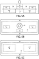
- FIGS. 5A-5C illustrate an exemplary assembly of active low impedance electrode 20 as shown in FIG. 4 .
- a flexible printed circuit board 27 mechanically supports and electrical connects battery cells V B1 and V B2 , op-amp U1, voltage sense contact 22, current flow contact 23 and active electrode coupler 24 within a foam adhesive 28.
- battery cells V B1 and V B2 preferably become activated upon active low impedance electrode 20 being removed from the packaging.
- a zinc air battery cells would be a good solution for this application.
- other mechanisms may be implemented to actively connect battery cells V B1 and V B2 to op-amp U1 when voltage sense contact 22, current flow contact 23 are applied to a patient. For example, a force of snapping the electrode wire on to active low impedance electrode 20 could activate battery cells V B1 and V B2 .
- op-amp U1 is commercially available with a power supply current less than 10uA, which would allow active low impedance electrode 20 to operate for a full length of time that it is applied to the patient even with very small battery cells V B1 and V B2 .
- Op-amp U1 reduces the electrode impedance by the amount of gain. For example active low impedance electrode 20 with a 150 KHz gain bandwidth will have a gain of 1000 at 150Hz which is the high end of the ECG spectrum.
- a patient skin electrode impedance of 1 Mohm will look like an impedance of only 1 Kohm at the ECG/EEG connection to ECG/EE monitoring device with an amplifier gain of 1000.
Landscapes
- Life Sciences & Earth Sciences (AREA)
- Health & Medical Sciences (AREA)
- Medical Informatics (AREA)
- Biophysics (AREA)
- Pathology (AREA)
- Engineering & Computer Science (AREA)
- Biomedical Technology (AREA)
- Heart & Thoracic Surgery (AREA)
- Physics & Mathematics (AREA)
- Molecular Biology (AREA)
- Surgery (AREA)
- Animal Behavior & Ethology (AREA)
- General Health & Medical Sciences (AREA)
- Public Health (AREA)
- Veterinary Medicine (AREA)
- Measurement And Recording Of Electrical Phenomena And Electrical Characteristics Of The Living Body (AREA)
Description
- The present invention generally relates to electrodes utilized by an electrical activity monitor for recording electrical activity of a biological organ (e.g., an electrocardiogram ("ECG") monitor for recording electrical activity of a patient's heart and an electroencephalogram ("EEG") monitor for recording electrical activity of a patient's brain). The present invention specifically relates to electrodes actively providing a low contact impedance for the ECG/EEG patient.
- As known in the art, ECG/EEG systems measure the voltages on a skin surface of a patient. These measured voltages are typically less than 1mV. Of note is a skin electrode interface impedance may vary dramatically from patient to patient. For example, these impedances may vary between 10K ohms and 10M ohms for a typical connection to the patient with standard electrodes. Such high impedances however are problematic with the use of standard electrodes.
- More particularly, any electrostatic coupling into a wire that connects the electrode to an amplifier input of a ECG/EEG monitor will result in current flow across the patient impedance, and any artifact signal generated by such an electrostatic coupling is directly proportional to the impedance of the electrode skin interface. To impede the generation of artifact signals, ECG/EEG monitors currently use shielded wires in order to minimize any electrostatic coupling.
- In addition to the direct coupling into an individual wire, electrostatic coupling may occur in a common mode coupling to the patient. Specifically, as implemented in the art, ECG/EEG monitors use one electrode as a reference electrode to provide for current flow between the patient and the ECG/EEG monitors. Typically, an active feedback loop is used to force most of the common mode current to flow through the reference electrode and minimize a common mode signal present on the measurement electrodes. The amplitude of the common mode signal is equal to current of the common mode coupling times the reference electrode impedance divided by the loop gain of the active feedback loop. The remaining signal then is cancelled by the matching of the input amplifiers in the input circuitry of the ECG/EEG monitors.
- In the case of emergency response where the patient is transported in an ambulance while being closely monitored for ECG, the sources of electrostatic coupling are substantial. For example, many possible sources of statically charged bodies are in the ambulance, and movement of charged bodies when driving down a road is very probable. Consequently, a patient with high contact impedance electrodes will typically have significant artifact present in the ECG when the ambulance is in motion, and the ambulance will have to pull over and stop in order to perform a 12-lead static-free ECG measurement to transmit to the hospital.
- Likewise, sources of electrostatic coupling may be substantial for a patient being closely monitored for EEG.
-
EP 2294979 A1 discloses a method and device for continuously and simultaneously measuring an impedance signal and a biopotential signal on a biological subject's skin. The method comprises the steps of: attaching input and output electrodes to the biological subject's skin; applying a predetermined alternating current having a first frequency to the output electrodes for creating an alternating voltage signal over the input electrodes, the first frequency being above a predetermined minimum frequency; measuring an input signal from the input electrodes, the input signal comprising a biopotential signal and the alternating voltage signal; extracting from said input signal the biopotential signal; extracting from said input signal the alternating voltage signal and determining the impedance signal from the alternating voltage signal. The alternating voltage signal is extracted by amplifying and demodulating the input signal using a control signal having a frequency equal to the first frequency of the applied alternating current. -
US 2003/006782 A1 discloses a method and system for measuring bioelectric impedance in the presence of interference. -
US 2011/295096 A1 discloses a method and system for electrode impedance measurement. - To address the disadvantages of the prior art, the present invention provides an electrode for actively reducing the skin electrode contact impedance to thereby minimize the effects of any electrostatic coupled signals on the ECG/EEG waveform. This substantially improves the quality of the ECG/EEG measurement, especially in presence of substantial electrostatic sources (e.g., a case of patient transport). With low electrode source impedance, a shielding of ECG/EEG cabling is not necessary, and an elimination of the shielding for the ECG/EEG cables consequently allows for low cost disposable ECG/EEG cables.
- One form of the present invention is an active low impedance electrode as defined in claim 1
- The foregoing form and other forms of the present invention as well as various features and advantages of the present invention will become further apparent from the following detailed description of various embodiments of the present invention read in conjunction with the accompanying drawings. The detailed description and drawings are merely illustrative of the present invention rather than limiting, the scope of the present invention being defined by the appended claims and equivalents thereof.
-
FIG. 1 illustrates exemplary embodiments of an electrical monitoring system in accordance with the present invention. -
FIG. 2 illustrates an exemplary embodiment of an active low impedance electrode in accordance with the present invention. -
FIG. 3 illustrates an exemplary embodiment of an electrical activity sensor of the present invention as shown inFIG. 2 . -
FIG. 4 illustrates an exemplary schematic embodiment of the electrical activity sensor shown inFIG. 2 . -
FIGS. 5A-5C respectively illustrate side, top and bottom views, of an exemplary assembly of an active low impedance electrode shown inFIG. 4 . - To facilitate understanding of the present invention, exemplary embodiments of the present invention will be provided herein directed to an electrical activity monitoring of a biological organ of a patient via an active low impedance electrode connecting an anatomical region of the patient to the electrical activity monitor.
- For example,
FIG. 1 illustrates a knownECG monitor 30 recordingelectrical activity 31 of aheart 11 of apatient 10 via an activelow impedance electrode 20a of the present invention connecting a thoracic region ofpatient 10 toECG monitor 30. Also by example,FIG. 1 illustratesknown EEG monitor 40 recordingelectrical activity 41 of abrain 12 of apatient 10 via an activelow impedance electrode 20b of the present invention connecting a cranial region ofpatient 10 toEEG monitor 40. - While only one
electrode 20a is shown forECG monitor 30 and only oneelectrode 20b is shown for EEG monitor for clarity ofFIG. 1 , one or more activelow impedance electrodes 20 of the present invention are employed in practice for a recording of electrical activity within an anatomical region as would be appreciated by one skilled in the art, and one or more conventional electrodes may be additionally employed in practice for the recording of electrical activity within the anatomical region as would be appreciated by one skilled in the art. - Referring to
FIG. 2 , an activelow impedance electrode 20 of the present invention employs anelectrical activity sensor 21, avoltage sense contact 22, acurrent flow contact 23 and anactive electrode coupler 24. In practice,voltage sense contact 22 andcurrent flow contact 23 are attached as known in the art to ananatomical region 13 of patient 10 (e.g., the cranial region or the thoracic region ofFIG. 1 ), andactive electrode coupler 24 is connected as known in the art to an electrical activity monitor 50 (e.g.,ECG monitor 30 orEEG monitor 40 ofFIG. 1 ). -
Voltage sense contact 22 applies a patient voltage VP on a skin surface ofanatomical region 13 to a voltage node NV ofelectrical activity sensor 21 having a high input impedance that effectively impedes any current flow fromanatomical region 13 intovoltage sense contact 22. As known in the art, fluctuation(s) of patient voltage VP are indicative of electrical activity of a biological organ within anatomical region 13 (e.g.,heart 11 orbrain 12 ofFIG. 1 ). -
Current flow contact 23 controls a directional flow of a sensor current IS between electricalanatomical region 13 and a current node NC ofelectrical activity sensor 21 having a low source impedance that effectively directs any current flow fromanatomical region 13 throughcurrent flow contact 22. The aforementioned attachment ofvoltage sense contract 22 andcurrent flow contact 23 toanatomical region 13 flow sensor current IS equaling a voltage drop betweenvoltage sense contact 22 andcurrent flow contact 23 divided by a patient contact impedance ZPC. This facilitates a sensing of patient voltage VP byelectrical activity sensor 21, particularly in a presence of a substantial flow of sensor current IS intoanatomical region 13. -
Active electrode coupler 24 applies a sensor voltage VS at a power node NP ofelectrical activity sensor 21 toelectrical activity monitor 50. Sensor voltage VS is representative of patient voltage VP whereby electrical activity monitor 50 may measure and record the electrical activity of the biological organ withinanatomical region 13. Of importance is an impedance ZAE ofactive electrode coupler 24 is significantly less (>>) than patient contact impedance ZPC. - In operation,
electrical activity sensor 21 generates sensor voltage VS and controls a directional flow of sensor current IS to establish an equivalence (=) of patient voltage VP to sensor voltage VS whereby any fluctuation of sensor voltage VS mirrors any fluctuation of voltage patient voltage VP. - A block diagram of an exemplary embodiment of
electrical activity sensor 21 is shown in block diagram shown inFIG. 3 and a schematic diagram of an exemplary embodiment ofelectrical activity sensor 21 is shown inFIG. 4 . - Referring to
FIGS. 3 and 4 , the exemplary embodiment ofelectrical activity sensor 21 employs aninternal power supply 25 and adifferential amplifier 26 as shown inFIG. 3 .Internal power supply 25 in the form of a split power supply as shown inFIG. 4 includes a series connection of two (2) small battery cells VB1 and VB2 for poweringdifferential amplifier 26 in the form of a low power operational amplifier ("op-amp") U1 via a connection to power/negative power supplies V+/V- of op-amp U1 as shown inFIG. 4 . A center point of the series connection of battery cells VB1 and VB2, a non-inverting input (+) of op-amp U1 andactive electrode coupler 24 are connected to power node NP. voltage sense contact ("VSC") 22 and an inverting input (-) of op-amp U1 and are connected to voltage node NV. Inverting input (-) of operational amplifier U1 has a high input impedance that effectively impedes any flow of current IP from anatomical region 13 (FIG. 2 ) throughvoltage sense contact 22 to op-amp U1. - Current flow contact ("CFC") 23 and an output of op-amp U1 are connected to current node NC whereby a feedback path of op-amp U1 from output to inverting input (-) includes
voltage sense contact 22 and currentlow contact 23. Specifically, in response toanatomical region 13 being connected tovoltage sense contact 22 and currentlow contact 23, a feedback of op-amp U1 will drive patient voltage VP to sensor voltage VS at non-inverting input (+) of operational amplifier U1 generated by the center point of the series connection of battery cells VB1 and VB2. Therefore, sensor voltage VS atactive electrode coupler 24 becomes approximately equivalent to patient voltage VP atvoltage sense contact 22. The larger a loop gain of op-amp U1, then the closer sensor voltage VS atactive electrode coupler 24 will match patient voltage VP atvoltage sense contact 22. - Sensor current IS as shown in
FIG. 3 may have a positive current flow IPS as shown inFIG. 4 from battery cell VB1 to positive power supply (V+) of operational amplifier U1 through an output drive circuitry of operational amplifier U1 toanatomical region 13 viacurrent flow contact 23. Conversely, sensor current Is as shown inFIG. 3 may have a negative current flow INS as shown inFIG. 4 fromanatomical region 13 viacurrent flow contact 23 through output drive circuitry of op-amp U1 to battery cell VB2 via negative power supply (V-) of op-amp U1. A voltage drop betweenvoltage sense contact 22 andcurrent flow contact 23 is a function of sensor current IS times a contact impedance ofcurrent flow contact 23. The equivalent contact impedance of the electrode is the voltage difference between VAE and VP divided by sensor current Is flowing throughactive electrode coupler 24. The difference between VAE and VP is equal to VF divided by the open loop gain of op-amp U1. Therefore, an equivalent contact impedance of thisactive electrode 20 is the contact impedance ofcurrent flow contact 23 divided by the open loop gain of op-amp U1. - In practice, active
low impedance electrode 20 as shown inFIG. 4 demonstrated a reduction in the electrode impedance. For example, at 5 Hz, which is the center of a ECG bandwidth, the active electrode impedance was only 430 ohms. The impedance of the contact with the patient at this frequency is 10M ohms. Also by example, at 60 Hz, activelow impedance electrode 20 reduced the electrode impedance from 8M ohms down to 4.1K ohms. This performance was achieved with a low power op-amp U1 operating with only 1uA of power supply current frominternal power supply 25. -
FIGS. 5A-5C illustrate an exemplary assembly of activelow impedance electrode 20 as shown inFIG. 4 . Specifically, a flexible printedcircuit board 27 mechanically supports and electrical connects battery cells VB1 and VB2, op-amp U1,voltage sense contact 22,current flow contact 23 andactive electrode coupler 24 within afoam adhesive 28. - In practice, battery cells VB1 and VB2 preferably become activated upon active
low impedance electrode 20 being removed from the packaging. A zinc air battery cells would be a good solution for this application. Alternatively, other mechanisms may be implemented to actively connect battery cells VB1 and VB2 to op-amp U1 whenvoltage sense contact 22,current flow contact 23 are applied to a patient. For example, a force of snapping the electrode wire on to activelow impedance electrode 20 could activate battery cells VB1 and VB2. - Also in practice, op-amp U1 is commercially available with a power supply current less than 10uA, which would allow active
low impedance electrode 20 to operate for a full length of time that it is applied to the patient even with very small battery cells VB1 and VB2. Op-amp U1 reduces the electrode impedance by the amount of gain. For example activelow impedance electrode 20 with a 150 KHz gain bandwidth will have a gain of 1000 at 150Hz which is the high end of the ECG spectrum. A patient skin electrode impedance of 1 Mohm will look like an impedance of only 1 Kohm at the ECG/EEG connection to ECG/EE monitoring device with an amplifier gain of 1000. - Referring to
FIGS. 1-5 , those having ordinary skill in the art will appreciate numerous benefits of the present invention including, but not limited to, a backward compatibility with standard electrode systems whereby an improvement of low contact impedance with a patient may be achieved without requiring any change in the known device or cabling hardware. - The invention is entirely defined by the appended claims 1-8.
Claims (8)
- An active low impedance electrode (20), comprising:an electrical activity sensor (21) including a voltage node, a current node and a power node;a voltage sense contact (22) operably connected to the voltage node to apply a patient voltage to the electrical activity sensor (21), the patient voltage being indicative of an electrical activity of an anatomical region (13) of a patient;a current flow contact (23) operably connected to the current node to facilitate a directional flow of sensor current between the electrical activity sensor (21) and the anatomical region (13);characterized by an active electrode coupler (24) operably connected to the power node; andin that, responsive to the voltage sense contact (22) and the current flow contact (23) being attached to the anatomical region (13) of the patient, the electrical activity sensor (21) is operable to control the directional flow of the sensor current between the electrical activity sensor (21) and the anatomical region (13) to establish an equivalence between the patient voltage at voltage sense contact (22) and a sensor voltage at active electrode coupler (24).
- The active low impedance electrode (20) of claim 1, wherein the electrical activity sensor (21) includes:
a differential amplifier (26) connected to the voltage node, the current node and the power node. - The active low impedance electrode (20) of claim 2, wherein the differential amplifier (26) includes:
an operational amplifier (U1) having a non-inverting input connected to the power node, an inverting input connected to the voltage node and an output connected to the current node. - The active low impedance electrode (20) of claim 1, wherein the electrical activity sensor (21) includes:
an internal power supply (25) connected to the power node. - The active low impedance electrode (20) of claim 4, wherein the internal power supply (25) includes:
a split power supply (VBI, VB2) connected to the power node. - The active low impedance electrode (20) of claim 4, wherein the electrical activity sensor (21) includes:
a differential amplifier (26) connected to the internal power supply (25). - The active low impedance electrode (20) of claim 6,
wherein the internal power supply (25) includes a split power supply (VBI, VB2); and
wherein the different amplifier (26) includes an operational amplifier (UI) having power supplies connected to the split power supply (VBI, VB2). - The active low impedance electrode (20) of any preceding claim,
wherein, responsive to the voltage sense contact (22) and the current flow contact (23) being attached to the anatomical region (13) of the patient, a patient contact impedance between the voltage sense contact (22) and the current flow contact (23) is greater than an active electrode impedance at the active electrode coupler (24).
Applications Claiming Priority (2)
| Application Number | Priority Date | Filing Date | Title |
|---|---|---|---|
| US201461924255P | 2014-01-07 | 2014-01-07 | |
| PCT/IB2015/050112 WO2015104657A1 (en) | 2014-01-07 | 2015-01-07 | Active low impedance electrode |
Publications (2)
| Publication Number | Publication Date |
|---|---|
| EP3091898A1 EP3091898A1 (en) | 2016-11-16 |
| EP3091898B1 true EP3091898B1 (en) | 2018-10-03 |
Family
ID=52462968
Family Applications (1)
| Application Number | Title | Priority Date | Filing Date |
|---|---|---|---|
| EP15703315.0A Active EP3091898B1 (en) | 2014-01-07 | 2015-01-07 | Active low impedance electrode |
Country Status (5)
| Country | Link |
|---|---|
| US (1) | US10321838B2 (en) |
| EP (1) | EP3091898B1 (en) |
| JP (1) | JP6494635B2 (en) |
| CN (1) | CN106028922B (en) |
| WO (1) | WO2015104657A1 (en) |
Families Citing this family (2)
| Publication number | Priority date | Publication date | Assignee | Title |
|---|---|---|---|---|
| KR102463174B1 (en) | 2017-07-31 | 2022-11-04 | 삼성전자주식회사 | Reconfigurable amplifier and amplifying method thereof |
| CN107898456A (en) * | 2017-11-13 | 2018-04-13 | 深圳贝特莱电子科技股份有限公司 | A kind of brain wave acquisition device and method based on active electrode |
Family Cites Families (18)
| Publication number | Priority date | Publication date | Assignee | Title |
|---|---|---|---|---|
| US3880146A (en) * | 1973-06-04 | 1975-04-29 | Donald B Everett | Noise compensation techniques for bioelectric potential sensing |
| JPH0543766Y2 (en) * | 1987-03-30 | 1993-11-05 | ||
| US6208888B1 (en) | 1999-02-03 | 2001-03-27 | Cardiac Pacemakers, Inc. | Voltage sensing system with input impedance balancing for electrocardiogram (ECG) sensing applications |
| AU2002327200B2 (en) * | 2001-07-06 | 2008-08-14 | Covidien Lp | System and method for measuring bioelectric impedance in the presence of interference |
| CN100438939C (en) * | 2002-03-14 | 2008-12-03 | 伊诺维思医疗公司 | Method and apparatus for detecting and transmitting electrical and related audio signals from a single, common anatomical site |
| US7092750B2 (en) * | 2003-04-16 | 2006-08-15 | Medtronic Emergency Response Systems, Inc. | ECG signal detection device |
| DE602005022282D1 (en) * | 2004-02-27 | 2010-08-26 | Koninkl Philips Electronics Nv | PORTABLE WIRELESS DEVICE FOR MONITORING, ANALYSIS AND COMMUNICATION OF THE PHYSIOLOGICAL STATUS |
| CN101778597A (en) * | 2007-08-20 | 2010-07-14 | 皇家飞利浦电子股份有限公司 | Method for measuring body parameters |
| EP2101408B1 (en) | 2008-03-11 | 2012-05-16 | CSEM Centre Suisse d'Electronique et de Microtechnique SA - Recherche et Développement | Floating front-end amplifier and one-wire measuring devices |
| WO2011007292A1 (en) * | 2009-07-13 | 2011-01-20 | Koninklijke Philips Electronics N.V. | Electro-physiological measurement with reduced motion artifacts |
| EP2294979B1 (en) * | 2009-09-14 | 2013-12-18 | Imec | Method and electronic medical device for simultaneously measuring an impedance and a biopotential signal |
| US9980662B2 (en) * | 2010-05-25 | 2018-05-29 | Neurowave Systems Inc. | Method and system for electrode impedance measurement |
| AU2011301761B2 (en) | 2010-09-13 | 2013-05-09 | Hear Ip Pty Ltd | A signal processing device for use in electroencephalography and a cable system incorporating the device |
| EP2442443B8 (en) | 2010-10-15 | 2018-02-07 | IMEC vzw | Multi-channel biopotential signal acquisition systems |
| JP5668604B2 (en) * | 2011-05-31 | 2015-02-12 | 株式会社デンソー | ECG detector |
| WO2013142944A1 (en) | 2012-03-29 | 2013-10-03 | George Townsend | Differential amplifier and electrode for measuring a biopotential |
| CN103197109A (en) * | 2013-02-22 | 2013-07-10 | 云南电力试验研究院(集团)有限公司电力研究院 | Circuit impedance used for electric parameter precision measurement and voltage active compensator |
| CN104079164B (en) * | 2014-06-30 | 2017-06-13 | 华为技术有限公司 | A kind of active EMI filter and electric power controller |
-
2015
- 2015-01-07 US US15/110,203 patent/US10321838B2/en active Active
- 2015-01-07 CN CN201580004015.8A patent/CN106028922B/en active Active
- 2015-01-07 EP EP15703315.0A patent/EP3091898B1/en active Active
- 2015-01-07 JP JP2016544114A patent/JP6494635B2/en active Active
- 2015-01-07 WO PCT/IB2015/050112 patent/WO2015104657A1/en active Application Filing
Non-Patent Citations (1)
| Title |
|---|
| None * |
Also Published As
| Publication number | Publication date |
|---|---|
| WO2015104657A1 (en) | 2015-07-16 |
| US20160331256A1 (en) | 2016-11-17 |
| CN106028922B (en) | 2019-07-23 |
| EP3091898A1 (en) | 2016-11-16 |
| US10321838B2 (en) | 2019-06-18 |
| JP2017500978A (en) | 2017-01-12 |
| JP6494635B2 (en) | 2019-04-03 |
| CN106028922A (en) | 2016-10-12 |
Similar Documents
| Publication | Publication Date | Title |
|---|---|---|
| EP2214555B1 (en) | Non-contact biopotential sensing method | |
| KR101206280B1 (en) | Electric contactless electric potential sensor circuit | |
| EP2453792B1 (en) | Electro-physiological measurement with reduced motion artifacts | |
| US8366628B2 (en) | Signal sensing in an implanted apparatus with an internal reference | |
| US9289178B2 (en) | Apparatus, unit measurer and method of measuring biological signal | |
| EP2394571B1 (en) | Apparatus and method for measuring a biological signal | |
| JP6713482B2 (en) | Active electrode, sensor system, and potential difference detection method | |
| JP7039002B2 (en) | Wearable biosensor and noise canceling circuit | |
| EP3209197B1 (en) | Simultaneous impedance testing method and apparatus | |
| EP3091898B1 (en) | Active low impedance electrode | |
| US9655541B2 (en) | Biosignal measurement apparatus | |
| US20220248975A1 (en) | Sensor circuit device for measuring a bio-potential or a bio-impedance | |
| US9968272B2 (en) | Device for detecting electric potentials | |
| JPH11512011A (en) | Electrophysiology equipment | |
| JP6530506B2 (en) | Measuring signal amplifier and energy supply method for measuring signal amplifier | |
| KR101504116B1 (en) | EEG signal detecting device | |
| US20230270367A1 (en) | Apparatus for biopotential measurement | |
| Chetelat et al. | Getting rid of the wires and connectors in physiological monitoring | |
| KR101772202B1 (en) | Monitoring device and method for attachment status of biopotential electrodes | |
| JP2023540055A (en) | High impedance and compact neural sensor front end | |
| JPS6315939A (en) | Light transmission electroencephalograph |
Legal Events
| Date | Code | Title | Description |
|---|---|---|---|
| PUAI | Public reference made under article 153(3) epc to a published international application that has entered the european phase |
Free format text: ORIGINAL CODE: 0009012 |
|
| 17P | Request for examination filed |
Effective date: 20160808 |
|
| AK | Designated contracting states |
Kind code of ref document: A1 Designated state(s): AL AT BE BG CH CY CZ DE DK EE ES FI FR GB GR HR HU IE IS IT LI LT LU LV MC MK MT NL NO PL PT RO RS SE SI SK SM TR |
|
| AX | Request for extension of the european patent |
Extension state: BA ME |
|
| STAA | Information on the status of an ep patent application or granted ep patent |
Free format text: STATUS: REQUEST FOR EXAMINATION WAS MADE |
|
| DAX | Request for extension of the european patent (deleted) | ||
| GRAP | Despatch of communication of intention to grant a patent |
Free format text: ORIGINAL CODE: EPIDOSNIGR1 |
|
| STAA | Information on the status of an ep patent application or granted ep patent |
Free format text: STATUS: GRANT OF PATENT IS INTENDED |
|
| INTG | Intention to grant announced |
Effective date: 20180418 |
|
| GRAS | Grant fee paid |
Free format text: ORIGINAL CODE: EPIDOSNIGR3 |
|
| GRAA | (expected) grant |
Free format text: ORIGINAL CODE: 0009210 |
|
| STAA | Information on the status of an ep patent application or granted ep patent |
Free format text: STATUS: THE PATENT HAS BEEN GRANTED |
|
| AK | Designated contracting states |
Kind code of ref document: B1 Designated state(s): AL AT BE BG CH CY CZ DE DK EE ES FI FR GB GR HR HU IE IS IT LI LT LU LV MC MK MT NL NO PL PT RO RS SE SI SK SM TR |
|
| REG | Reference to a national code |
Ref country code: GB Ref legal event code: FG4D |
|
| REG | Reference to a national code |
Ref country code: CH Ref legal event code: EP Ref country code: AT Ref legal event code: REF Ref document number: 1047739 Country of ref document: AT Kind code of ref document: T Effective date: 20181015 |
|
| REG | Reference to a national code |
Ref country code: IE Ref legal event code: FG4D Ref country code: DE Ref legal event code: R096 Ref document number: 602015017453 Country of ref document: DE |
|
| REG | Reference to a national code |
Ref country code: NL Ref legal event code: MP Effective date: 20181003 |
|
| REG | Reference to a national code |
Ref country code: LT Ref legal event code: MG4D |
|
| REG | Reference to a national code |
Ref country code: AT Ref legal event code: MK05 Ref document number: 1047739 Country of ref document: AT Kind code of ref document: T Effective date: 20181003 |
|
| PG25 | Lapsed in a contracting state [announced via postgrant information from national office to epo] |
Ref country code: NL Free format text: LAPSE BECAUSE OF FAILURE TO SUBMIT A TRANSLATION OF THE DESCRIPTION OR TO PAY THE FEE WITHIN THE PRESCRIBED TIME-LIMIT Effective date: 20181003 |
|
| PG25 | Lapsed in a contracting state [announced via postgrant information from national office to epo] |
Ref country code: LT Free format text: LAPSE BECAUSE OF FAILURE TO SUBMIT A TRANSLATION OF THE DESCRIPTION OR TO PAY THE FEE WITHIN THE PRESCRIBED TIME-LIMIT Effective date: 20181003 Ref country code: NO Free format text: LAPSE BECAUSE OF FAILURE TO SUBMIT A TRANSLATION OF THE DESCRIPTION OR TO PAY THE FEE WITHIN THE PRESCRIBED TIME-LIMIT Effective date: 20190103 Ref country code: HR Free format text: LAPSE BECAUSE OF FAILURE TO SUBMIT A TRANSLATION OF THE DESCRIPTION OR TO PAY THE FEE WITHIN THE PRESCRIBED TIME-LIMIT Effective date: 20181003 Ref country code: IS Free format text: LAPSE BECAUSE OF FAILURE TO SUBMIT A TRANSLATION OF THE DESCRIPTION OR TO PAY THE FEE WITHIN THE PRESCRIBED TIME-LIMIT Effective date: 20190203 Ref country code: FI Free format text: LAPSE BECAUSE OF FAILURE TO SUBMIT A TRANSLATION OF THE DESCRIPTION OR TO PAY THE FEE WITHIN THE PRESCRIBED TIME-LIMIT Effective date: 20181003 Ref country code: AT Free format text: LAPSE BECAUSE OF FAILURE TO SUBMIT A TRANSLATION OF THE DESCRIPTION OR TO PAY THE FEE WITHIN THE PRESCRIBED TIME-LIMIT Effective date: 20181003 Ref country code: CZ Free format text: LAPSE BECAUSE OF FAILURE TO SUBMIT A TRANSLATION OF THE DESCRIPTION OR TO PAY THE FEE WITHIN THE PRESCRIBED TIME-LIMIT Effective date: 20181003 Ref country code: LV Free format text: LAPSE BECAUSE OF FAILURE TO SUBMIT A TRANSLATION OF THE DESCRIPTION OR TO PAY THE FEE WITHIN THE PRESCRIBED TIME-LIMIT Effective date: 20181003 Ref country code: ES Free format text: LAPSE BECAUSE OF FAILURE TO SUBMIT A TRANSLATION OF THE DESCRIPTION OR TO PAY THE FEE WITHIN THE PRESCRIBED TIME-LIMIT Effective date: 20181003 Ref country code: BG Free format text: LAPSE BECAUSE OF FAILURE TO SUBMIT A TRANSLATION OF THE DESCRIPTION OR TO PAY THE FEE WITHIN THE PRESCRIBED TIME-LIMIT Effective date: 20190103 Ref country code: PL Free format text: LAPSE BECAUSE OF FAILURE TO SUBMIT A TRANSLATION OF THE DESCRIPTION OR TO PAY THE FEE WITHIN THE PRESCRIBED TIME-LIMIT Effective date: 20181003 |
|
| PG25 | Lapsed in a contracting state [announced via postgrant information from national office to epo] |
Ref country code: AL Free format text: LAPSE BECAUSE OF FAILURE TO SUBMIT A TRANSLATION OF THE DESCRIPTION OR TO PAY THE FEE WITHIN THE PRESCRIBED TIME-LIMIT Effective date: 20181003 Ref country code: SE Free format text: LAPSE BECAUSE OF FAILURE TO SUBMIT A TRANSLATION OF THE DESCRIPTION OR TO PAY THE FEE WITHIN THE PRESCRIBED TIME-LIMIT Effective date: 20181003 Ref country code: PT Free format text: LAPSE BECAUSE OF FAILURE TO SUBMIT A TRANSLATION OF THE DESCRIPTION OR TO PAY THE FEE WITHIN THE PRESCRIBED TIME-LIMIT Effective date: 20190203 Ref country code: RS Free format text: LAPSE BECAUSE OF FAILURE TO SUBMIT A TRANSLATION OF THE DESCRIPTION OR TO PAY THE FEE WITHIN THE PRESCRIBED TIME-LIMIT Effective date: 20181003 Ref country code: GR Free format text: LAPSE BECAUSE OF FAILURE TO SUBMIT A TRANSLATION OF THE DESCRIPTION OR TO PAY THE FEE WITHIN THE PRESCRIBED TIME-LIMIT Effective date: 20190104 |
|
| REG | Reference to a national code |
Ref country code: DE Ref legal event code: R097 Ref document number: 602015017453 Country of ref document: DE |
|
| PG25 | Lapsed in a contracting state [announced via postgrant information from national office to epo] |
Ref country code: DK Free format text: LAPSE BECAUSE OF FAILURE TO SUBMIT A TRANSLATION OF THE DESCRIPTION OR TO PAY THE FEE WITHIN THE PRESCRIBED TIME-LIMIT Effective date: 20181003 Ref country code: IT Free format text: LAPSE BECAUSE OF FAILURE TO SUBMIT A TRANSLATION OF THE DESCRIPTION OR TO PAY THE FEE WITHIN THE PRESCRIBED TIME-LIMIT Effective date: 20181003 |
|
| PLBE | No opposition filed within time limit |
Free format text: ORIGINAL CODE: 0009261 |
|
| STAA | Information on the status of an ep patent application or granted ep patent |
Free format text: STATUS: NO OPPOSITION FILED WITHIN TIME LIMIT |
|
| PG25 | Lapsed in a contracting state [announced via postgrant information from national office to epo] |
Ref country code: MC Free format text: LAPSE BECAUSE OF FAILURE TO SUBMIT A TRANSLATION OF THE DESCRIPTION OR TO PAY THE FEE WITHIN THE PRESCRIBED TIME-LIMIT Effective date: 20181003 Ref country code: RO Free format text: LAPSE BECAUSE OF FAILURE TO SUBMIT A TRANSLATION OF THE DESCRIPTION OR TO PAY THE FEE WITHIN THE PRESCRIBED TIME-LIMIT Effective date: 20181003 Ref country code: SM Free format text: LAPSE BECAUSE OF FAILURE TO SUBMIT A TRANSLATION OF THE DESCRIPTION OR TO PAY THE FEE WITHIN THE PRESCRIBED TIME-LIMIT Effective date: 20181003 Ref country code: EE Free format text: LAPSE BECAUSE OF FAILURE TO SUBMIT A TRANSLATION OF THE DESCRIPTION OR TO PAY THE FEE WITHIN THE PRESCRIBED TIME-LIMIT Effective date: 20181003 Ref country code: SK Free format text: LAPSE BECAUSE OF FAILURE TO SUBMIT A TRANSLATION OF THE DESCRIPTION OR TO PAY THE FEE WITHIN THE PRESCRIBED TIME-LIMIT Effective date: 20181003 |
|
| REG | Reference to a national code |
Ref country code: CH Ref legal event code: PL |
|
| 26N | No opposition filed |
Effective date: 20190704 |
|
| PG25 | Lapsed in a contracting state [announced via postgrant information from national office to epo] |
Ref country code: LU Free format text: LAPSE BECAUSE OF NON-PAYMENT OF DUE FEES Effective date: 20190107 |
|
| REG | Reference to a national code |
Ref country code: BE Ref legal event code: MM Effective date: 20190131 |
|
| REG | Reference to a national code |
Ref country code: IE Ref legal event code: MM4A |
|
| PG25 | Lapsed in a contracting state [announced via postgrant information from national office to epo] |
Ref country code: SI Free format text: LAPSE BECAUSE OF FAILURE TO SUBMIT A TRANSLATION OF THE DESCRIPTION OR TO PAY THE FEE WITHIN THE PRESCRIBED TIME-LIMIT Effective date: 20181003 |
|
| PG25 | Lapsed in a contracting state [announced via postgrant information from national office to epo] |
Ref country code: BE Free format text: LAPSE BECAUSE OF NON-PAYMENT OF DUE FEES Effective date: 20190131 |
|
| PG25 | Lapsed in a contracting state [announced via postgrant information from national office to epo] |
Ref country code: CH Free format text: LAPSE BECAUSE OF NON-PAYMENT OF DUE FEES Effective date: 20190131 Ref country code: LI Free format text: LAPSE BECAUSE OF NON-PAYMENT OF DUE FEES Effective date: 20190131 |
|
| PG25 | Lapsed in a contracting state [announced via postgrant information from national office to epo] |
Ref country code: IE Free format text: LAPSE BECAUSE OF NON-PAYMENT OF DUE FEES Effective date: 20190107 |
|
| PG25 | Lapsed in a contracting state [announced via postgrant information from national office to epo] |
Ref country code: TR Free format text: LAPSE BECAUSE OF FAILURE TO SUBMIT A TRANSLATION OF THE DESCRIPTION OR TO PAY THE FEE WITHIN THE PRESCRIBED TIME-LIMIT Effective date: 20181003 |
|
| PG25 | Lapsed in a contracting state [announced via postgrant information from national office to epo] |
Ref country code: MT Free format text: LAPSE BECAUSE OF NON-PAYMENT OF DUE FEES Effective date: 20190107 |
|
| REG | Reference to a national code |
Ref country code: DE Ref legal event code: R079 Ref document number: 602015017453 Country of ref document: DE Free format text: PREVIOUS MAIN CLASS: A61B0005040800 Ipc: A61B0005280000 |
|
| PG25 | Lapsed in a contracting state [announced via postgrant information from national office to epo] |
Ref country code: CY Free format text: LAPSE BECAUSE OF FAILURE TO SUBMIT A TRANSLATION OF THE DESCRIPTION OR TO PAY THE FEE WITHIN THE PRESCRIBED TIME-LIMIT Effective date: 20181003 |
|
| PG25 | Lapsed in a contracting state [announced via postgrant information from national office to epo] |
Ref country code: HU Free format text: LAPSE BECAUSE OF FAILURE TO SUBMIT A TRANSLATION OF THE DESCRIPTION OR TO PAY THE FEE WITHIN THE PRESCRIBED TIME-LIMIT; INVALID AB INITIO Effective date: 20150107 |
|
| PG25 | Lapsed in a contracting state [announced via postgrant information from national office to epo] |
Ref country code: MK Free format text: LAPSE BECAUSE OF FAILURE TO SUBMIT A TRANSLATION OF THE DESCRIPTION OR TO PAY THE FEE WITHIN THE PRESCRIBED TIME-LIMIT Effective date: 20181003 |
|
| PGFP | Annual fee paid to national office [announced via postgrant information from national office to epo] |
Ref country code: FR Payment date: 20230124 Year of fee payment: 9 |
|
| PGFP | Annual fee paid to national office [announced via postgrant information from national office to epo] |
Ref country code: DE Payment date: 20240129 Year of fee payment: 10 Ref country code: GB Payment date: 20240123 Year of fee payment: 10 |