EP3091132A1 - Prefabricated, modular structure - Google Patents
Prefabricated, modular structure Download PDFInfo
- Publication number
- EP3091132A1 EP3091132A1 EP16168489.9A EP16168489A EP3091132A1 EP 3091132 A1 EP3091132 A1 EP 3091132A1 EP 16168489 A EP16168489 A EP 16168489A EP 3091132 A1 EP3091132 A1 EP 3091132A1
- Authority
- EP
- European Patent Office
- Prior art keywords
- elements
- vertical
- horizontal
- main
- modular
- Prior art date
- Legal status (The legal status is an assumption and is not a legal conclusion. Google has not performed a legal analysis and makes no representation as to the accuracy of the status listed.)
- Withdrawn
Links
Images


Classifications
-
- E—FIXED CONSTRUCTIONS
- E04—BUILDING
- E04B—GENERAL BUILDING CONSTRUCTIONS; WALLS, e.g. PARTITIONS; ROOFS; FLOORS; CEILINGS; INSULATION OR OTHER PROTECTION OF BUILDINGS
- E04B1/00—Constructions in general; Structures which are not restricted either to walls, e.g. partitions, or floors or ceilings or roofs
- E04B1/343—Structures characterised by movable, separable, or collapsible parts, e.g. for transport
- E04B1/34315—Structures characterised by movable, separable, or collapsible parts, e.g. for transport characterised by separable parts
-
- E—FIXED CONSTRUCTIONS
- E04—BUILDING
- E04H—BUILDINGS OR LIKE STRUCTURES FOR PARTICULAR PURPOSES; SWIMMING OR SPLASH BATHS OR POOLS; MASTS; FENCING; TENTS OR CANOPIES, IN GENERAL
- E04H3/00—Buildings or groups of buildings for public or similar purposes; Institutions, e.g. infirmaries or prisons
- E04H3/08—Hospitals, infirmaries, or the like; Schools; Prisons
-
- E—FIXED CONSTRUCTIONS
- E04—BUILDING
- E04B—GENERAL BUILDING CONSTRUCTIONS; WALLS, e.g. PARTITIONS; ROOFS; FLOORS; CEILINGS; INSULATION OR OTHER PROTECTION OF BUILDINGS
- E04B1/00—Constructions in general; Structures which are not restricted either to walls, e.g. partitions, or floors or ceilings or roofs
- E04B2001/0053—Buildings characterised by their shape or layout grid
- E04B2001/0076—Buildings with specific right-angled horizontal layout grid
Definitions
- the invention refers to a prefabricated modular structure for manufacturing buildings of various kind during emergency situations, like schools, hospitals, temporary assistance centres, and similar inhabited structures, with different and variable configurations, and with reduced times for assembling and installing and for disassembling the various component parts of the same structure.
- This prefabricated modular structure is realized with component elements with standard dimensions such that all the component elements may be transported without problems onto transport means of any kind, like wagons, trucks, containers and the like, the structure being also adapted to be assembled and disassembled into different places and positions.
- the present invention refers to a prefabricated modular structure, adapted to be used for manufacturing buildings of various kind during emergency situations, like schools, hospitals, temporary assistance centres, and similar inhabited structures, with different and variable configurations as desired, and with reduced times for assembling and installing and disassembling the various components elements of the same structure.
- This prefabricated modular structure is realized with the component elements that will be described, having standard dimensions such to allow to transport without problems all the component elements onto transports means of any kind, like wagons, trucks, containers and the like, the structure being also adapted to be assembled and disassembled into different places and positions.
- the modular component elements used for realizing the prefabricated structure are the following:
- the main modular element 5 is substantially constituted by a vertical closed flat frame 12 with rectangular shape, forming a wall with the upper and lower horizontal sides that are shorter, and parallel to each other, and with the vertical sides that are parallel to each other.
- the width of such main element is selected smaller than the internal free width of a standard container ISO of 20 ft, in such a way that the main modular element 5 may be housed also into the containers and transported with these latter, whereas the height of the same main element may theoretically be such as to reach the internal free depth of each container (of about 6 meters), but this height is advantageously selected with a smaller size (of about 2,560 meters), in such a way that each container may contain two pallets placed side by side and supporting various main modular elements, and that the internal free height of each assembled module be many times greater than 2,400 meters, that constitutes a correct height for the operation and that complies with the building law relating to the stationary buildings structures of traditional type.
- Each wall frame 12 is realized with peripheral metallic walls, that may be full or may also define to each other an internal free space into which there are inserted some insulating panels made of insulating material of traditional type (e.g. polystyrene), that in the example are constituted by two panels 13 and 14 of the male and female type with standard thickness and width (in the present example of 50 mm and 1 meter, respectively).
- insulating panels made of insulating material of traditional type (e.g. polystyrene), that in the example are constituted by two panels 13 and 14 of the male and female type with standard thickness and width (in the present example of 50 mm and 1 meter, respectively).
- Each flat frame 12 may also be made hollow into its interior, and without insulating panels, and in such case it provides a reinforcing structure that will be described, or it may provide also through openings through the relative insulating panels 13 and 14, with the shape of doors and windows (not shown in the Figure), and the insulating panels may include also windows and door frames of any type.
- Each frame 12 furthermore, has the upper 15 and lower 16 horizontal sides with the same profile, slightly hollowed for the entire length of the relative side, that in the upper side 15 performs the function of gutter for collecting and draining of rainwater, and in the lower side 16 serves for supporting the floor of the modular structure.
- the lower side 16 there are also fixed at least two support feet 17 and 18, identical and opportunely shaped for being able to be arranged directly onto the ground or onto suitable support platforms (not shown) applied onto the ground, such support feet being arranged closed to the correspondent vertical side of the frame, as visible in Fig.
- the two vertical sides 19 and 20 of any type of frame acting like stanchions, have the same hollowed profile for a determined depth for all the height of the relative side and have reduced thickness with respect to the upper and lower horizontal sides 15, 16 and perform, in addition to the load bearing function, also the function of gutter descending element, for draining the rainwater on to the ground, as well as of interconnecting element among the frames.
- each vertical stanchion that is constituted by a metallic section bar 21 that, in the illustrated example, is shaped with a square cross-section provided with an internal circular hole 22 for the passage of the rainwater and its conveying downward, and into its side turned inward the main modular element 5 the section bar 21 is lengthened with two short projections 23 and 24, that are parallel and spaced away to each other for housing and securing the correspondent end portion of the relative insulating panel, whereas into the side opposite to the above-mentioned side the section bar 21 is shaped with two additional short projections (not shown), that are parallel and close to each other and are provided for the connection of the same section bar with each first connecting modular element 6, and these additional projections are bored in positions correspondent to each other, for allowing the passage of correspondent bolts 25 for fixing the relative connecting element 6.
- each vertical stanchion may be shaped also with conformations different from that described, provided that it always performs the same function, thus without departing from the protection sphere of the
- the first connecting element 6, named also column, is substantially constituted by a first curved element 26 and by a second curved element 27 both having a relative curved portion 28 and 29 that are parallel and spaced away to each other, of which the first curved element 26 has a radius of curvature greater than that one of the second curved element 27, and both said curved elements are extended in the vertical direction for the entire height of each stanchion.
- the first curved element 26 and the second curved element 27 are lengthened with relative short horizontal rectilinear end portions (not indicated), entering for a determined depth into the hollow (not shown) of the adjacent vertical side of the relative main element 5, and both the end portions of each first and second curved element 26, 27 are bored in positions coinciding with the positions of the relative through holes of the additional projections of the section bar 21 of a relative vertical stanchion.
- first and second curved elements 26 and 27 there is also provided integral a short flat flange 30, orthogonal to the same end portions and adapted to be arranged into external contact to the vertical side of a main element 5, for all the width of the same side, whereas near the other one of the horizontal end portions of such first and second curved elements 26 and 27 there is provided integral an additional short flat flange 31, orthogonal to the same end portions and identical to the previous flange, and adapted to be arranged into external contact to the vertical side of another main element 5, orthogonal to the previous main element 5, and for the entire width of the same side.
- the two flat flanges 30 and 31 are secured onto the relative first curved element 26 and second curved element 27, in a such position that, when these curved elements are secured to the relative vertical stanchions 21 (see Fig. 2 ) of the two main elements 5 arranged orthogonal to each other as visible from this Figure, the correspondent curved portion 28 and 29 of these curved elements be extended for the entire distance existing between the two flat flanges 30 and 31, in a manner do not leave free spaces between the same flanges.
- the junction between the two main elements 5 arranged orthogonal to each other, as shown in Fig. 2 is effected by levelling at first the horizontal lower sides of such main elements 5 with respect to the ground, by regulating the height of the support feet 17 and 18, as already described previously, and then by introducing a fixing bolt 25 into the through holes coinciding to each other of both the horizontal end portions of said first and second curved elements 26 and 27 and the additional projections of each vertical section bar 21 of the stanchions, and moreover by introducing some U-shaped bars 32 into the space existing between both the end portions of said first and second curved elements 26 and 27 and the opposite flat side (not indicated) of the same vertical section bar.
- the object of such U-shaped bars 32 is to lock the heads 33 of the fixing bolts 25, adjacent to the same bars, thereby preventing the bolts from being unscrewed from the outside.
- Such second connecting element 7 is provided for joining to each other the section bars adjacent to each other of each main element 5, which section bars are identical and comprise the same connection devices of the ones previously described (that is a fixing bolt 25 and a U-shaped bar 32), the connecting element referred to being substantially constituted by two curved elements 27 identical to the previously described curved element 27, of which a first curved element 27 is provided for joining the section bar 21 of one of the vertical main elements 5 (in this case, of the upper one element in the Fig.
- a second curved element 27 is symmetrical and aligned with respect to the first curved element 27, and is provided for joining the section bar 21 of the horizontal main element 5 with the section bar 21 of the third main element 5 arranged vertical (in this case, of the lower element in the Fig. 3 ).
- first curved element 27 is joined to a short flat flange 34, placed near one end portion of the same curved element and adapted to be arranged into external contact to the vertical side of the vertical and upper main element 5, and such first curved element 27 is also joined to an additional short flat flange 35, placed near the other end portion of the same curved element, and adapted to be arranged into external contact to the vertical side of the horizontal main element 5.
- the second curved element 27 is joined to said additional flat flange 35, situated near an end portion of the same curved element and adapted to be arranged into external contact to the vertical side of the horizontal main element 5, and such second curved element 27 is also joined to an additional short flat flange 36, placed near the other end portion of the same curved element and adapted to be arranged into external contact to the vertical side of the other lower vertical main element 5.
- the second connecting element 7, finally, is constituted by a rectilinear portion 37 that in the example of Fig. 3 is arranged vertical, and which is extended in the vertical direction for the entire height of the stanchions, and this rectilinear portion 37 is joined with the flat flange 34 near an end portion of the same rectilinear portion, and such rectilinear portion 37 is also joined to the additional flat flange 36 near the other end portion of the same rectilinear portion.
- the third connecting modular element 8 for joining to each other four main modular elements 5, of which two elements (that in the Figure are the vertically arranged elements 5) are arranged aligned to and spaced away from each other by the third connecting element 8, and the other two elements (that in the Figure are the horizontally arranged elements 5), are oriented horizontally and orthogonally with respect to the first two vertical elements 5, and are also arranged aligned to and spaced away from each other by the same third connecting element 8, and also in this case a relative insulating panel is mounted onto all said main modular elements 5.
- Such third connecting element 8 is provided for joining to each other the section bars adjacent to each other of each main element 5, which section bars are identical and comprise the same connecting devices of the ones previously described (that is a fixing bolt 25 and a U-shaped bar 32), the connecting element referred to being substantially constituted by two curved elements 27 identical to and placed as the curved elements 27, as well as joined to the same flanges 34, 35 e 36 as described in the Fig. 3 , and such third connecting element 8 being also constituted by two additional curved elements 27 identical to and placed as the just described curved elements 27, however symmetrical and aligned with respect to these latters.
- the first one of the additional curved elements 27 is joined to a short flat flange 38, placed near one end portion of the same curved element and adapted to be arranged into external contact to the vertical side of one of the horizontal main elements 5 (in the example of Fig. 4 , of the left-side horizontal main element 5), and such first additional curved element 27 is also joined to said flat flange 34 near the other end portion of the same curved element.
- the second one of the curved elements 27 is joined to the flat flange 38 situated near an end portion of the same curved element and is also joined to said flat flange 36, situated near the other end portion of the same curved element.
- the fourth connecting modular element 9, constituting the floor of the present structure which is substantially constituted both by first horizontal and rectilinear metallic cross-pieces 39, that are identical to and arranged parallel from each other and in the longitudinal direction of different main modular elements 5 aligned and joined to each other, and by second horizontal and rectilinear metallic cross-pieces 40, that are identical to and smaller than the first cross-pieces 39, and which are arranged parallel to each other and in the transversal direction of different main modular elements 5 aligned and joined to each other, and all the first and second cross-pieces 39 and 40 are joined to each other and with the lower sides 16 of said modular elements 5 aligned and joined from each other, with such an arrangement as to be able to house some horizontal floor plates 41 identical and arranged horizontally aligned to each other, forming the walkable floor.
- Each first longitudinal horizontal cross-piece 39 and each second transversal horizontal cross-piece element 40 has an upper fixed section bar 42 and two movable lower shells 43, of which the upper fixed section bar 42 has a cross-section shaped almost of square shape, and is extended downward with two short and thin vertical side walls 44 and 45, parallel and spaced away to each other, and bored at determined intervals for the whole length of the same section bar, and the movable lower shells 43 are symmetrical to each other and are formed each by a short upper vertical portion 48 and a C-shaped lower portion 49, wherein the C-shaped portion of each shell 43 is bored at determined intervals for its whole length, at positions that are coinciding with those ones of the holes of the side walls 44 and 45 of the section bar 42, for allowing the passage of a correspondent fixing bolt 50, the head of which (not shown) is arranged externally to the shell wall and the stem of which (not shown) is at first inserted into a correspondent hole of the section bar side wall respectively opposite, and then is tight
- Such shells 43 are to support the relative side edge of a horizontal floor plate 41, and in the indicated example there are shown two floor plates 41 aligned and spaced away to each other by the cross-piece 39, the side edges 51 and 52 of which are laid on to a relative shell 43 and supported by the same.
- the fourth connecting modular element 9 comprises also two additional lower movable shells 53 and 54, that are identical to such movable lower shells 43, which additional shells are applied to the short and thin side vertical walls 55 and 56, which are identical to the preceding vertical walls 44 and 45, and are extended downward from the lower side 16 of each main modular element 5, each shell of which is bored for the passage of a fixing bolt 57, that is inserted also through correspondent through holes (not shown) provided at determined intervals for the whole length of such side walls 55 and 56.
- each floor plate 41 with a determinate size in to the relative housing position of a floor support structure obtained as described it is then sufficient at first to loose the fixing bolts which are foreseen, and then to displace each shell in the horizontal direction up to the position suitable to support the correspondent side edge of the floor plate with this size. Finally, on to the shells there is applied the relative floor plate and the shells are then secured in this position by clamping their fixing bolts to the relative side walls of the same plate.
- the visible modular structure is constituted both by two main elements 5 assembled aligned to each other, and into which it is inserted a relative insulating panel 13 and 14, and by an additional modular element 5 internally empty (namely, without insulating panels) that is secured orthogonally on to the front of the above-described main elements 5, and by a longitudinal cross-piece 39 and by two transversal cross-pieces 40, supporting the longitudinal cross-piece 39, and each one which is secured as it will be described to the centre line of the relative main element 5.
- Such a longitudinal cross-piece 39 is supported also onto the ground by means of support feet 59 adjustable in height and identical to the feet 17 and 18 of each main element 5, which are secured along the cross-piece 39 at determined intervals (in the example, there are shown four support feet 59), and the free end portions of the longitudinal cross-piece 39 are bolted, through head plates (not shown), to the centre line respectively of a first and second pair of main elements (not shown), assembled aligned to each other, that are fixed in a position orthogonal to the relative vertical sides 19 and 20 of two above-described main elements 5.
- each transversal cross-piece 40 is not provided with lower support feet, and is supported with a free end portion thereof by a head plate (not shown), that is bolted to the centre line of the lower side 16 of the two relative main elements 5, and with the other free end portion thereof is supported by another head plate (not shown), that is bolted to the centre line of the lower side of two additional main elements (not shown), arranged aligned to each other, which are secured orthogonally to the vertical side 20 of the empty element 5, in a position parallel to the preceding two main elements 5 visible in the Figure.
- the longitudinal cross-piece 39 is supported by the transversal cross-pieces 40 thanks to correspondent hollows (not shown) provided in the central zone of the transversal cross-pieces, into which hollows the longitudinal cross-piece 39 is inserted.
- the two main elements 5 aligned to each other are joined to the other main element 5 orthogonally thereto by means of the second connecting elements 7 described with reference to the Fig. 3 .
- the floor structure realized by assembling to each other the above-described component elements, in the considered example forms a set of squared painted backgrounds (not shown), into which there are inserted relative floor plates 41 (not shown in the Figure), arranged at the same level, which are then locked in position as described with reference to the Fig. 6 . Referring always to the Fig.
- the empty main element 5 is reinforced with a reinforcing structure constituted by the fifth modular element 10, and formed by a vertical bar 60, that is inserted into the empty space of a main element 5 and applied into contact with the relative vertical side 19 of this main element, to which it is opportunely secured.
- a vertical bar is also fixed in the same manner to the other vertical side 20 of this main element 5, that as already described is fixed to two additional main elements arranged parallel to the two main elements 5 visible in this Figure, and this additional vertical bar and the additional main elements are not represented here for simplicity.
- each side edge of each one of the flat roofs 61 it is applied a fixing flange 62, shaped with a short and thin horizontal rectilinear portion 63, adapted to be arranged into contact to the upper surface of the side edge of the roof 61, and such a flange horizontal portion is bent for forming a first short and thin vertical portion 64, adapted to be arranged into contact to the external side surface 65 of the roof side edge, and for forming also a second short and thin vertical portion 66 directed downward, which is arranged parallel to the first vertical portion 64 and is joined to the same and it is extended downward in such a way that, when the flange 62 is applied in position, it may enter slightly the hollow 67 defined in the upper hollowed side 15 of the main element.
- Such a first flange vertical portion 64 is still bent downward for forming a short and thin horizontal portion (not shown) and a short and thin lower vertical portion (also not shown), ending with an end portion bent like a hook 68.
- the fastening in position of each side edge of the flat roof 61 with the relative vertical section bar 21 is then effected by arranging at first the horizontal portion 63 and the first vertical portion 64 of the flange respectively to the upper surface and to the external side surface 65 of the roof side edge, in a manner that the second vertical portion of the flange 66 enters partially the hollow 67 and that the lower horizontal portion of the flange be arranged below the lower surface of the roof side edge and that the lower vertical portion of the flange be spaced away laterally from said hollowed horizontal side 15.
- each roof side edge is laid partially on to the hollowed horizontal side 15 and the fastening and locking in position of the roof is obtained by means of said flange 62 and a sliding bracket 69, formed by a rectilinear vertical portion 70, the upper end portion 71 of which shaped as a hook is adapted to be hooked with the hook 68, and which is also joined to a short horizontal portion 72, adapted to abut in the lower side on to the upper horizontal side 15, and the vertical portion 70 of the bracket 69 is also bored for inserting a bolt 73, onto which a wing head 74 may be screwed and unscrewed.
- bracket 69 is hooked with its hook 71 into the hook 68 of the flange 62 and the horizontal portion of bracket 72 is pushed in abutment in the lower part on to the upper hollowed side 15, thereafter said wing head 74 is screwed onto the bolt 73 up to the bracket 69 is firmly tightened to said flange 62 and the upper hollowed side 15. Then, under the condition, as it is visible in the Fig.
- the vertical portions 66 of the two flanges 62 are spaced away to each other, by defining a vertical passage (not shown) into which rainwater penetrate, that fall into the gutter hollow 67 of the horizontal side 15, from which they are conveyed into the inlet of the relative gutter descending element of each vertical side of the main element 5, and are therefore drained onto the ground.
- Fig. 8 it is shown a modular structure formed by the same component elements of Fig. 5 , comprising the floor plates 41 and the roofs 61 (of which in the Figure only a roof 61 is visible), and these component elements are joined to two additional main elements 5 arranged parallel to the empty main element 5, of which the left side main element has on opening 75 for entering into the same modular structure.
- Figs. 9-18 there are shown the assembling phases performed for assembling the different modular elements of a modular structure realized in the base building configuration, identical to and with the same component elements described in the Figs. 5-8 .
- such a base modular structure of having the dimensions of two base modules has the external dimensions of about 2,400 meters x 4,700 meters and a height of about 2,650 meters. All the component elements of this structure may be inserted into one pallet with a length of 2,852 meters, width of 2,280 meters and height of 1,190 meters, which may be introduced into a standard container ISO of 20 feet, into which therefore there may be introduced four above-mentioned pallets, with an obtainable total volume equal to about four times the transported volume.
- Figs. 19-24 it is shown in which manner the above-described base modular structures may be integrated with some special modules that will be described hereinafter, which are adapted to allow to realize some rooms of a dimension double than that of the base module, namely with ports of about m. 4,500 without columns and/or intermediate vertical structures.
- FIG. 19 there are shown as example two base modular structures that are joined to each other by a special module, which base structures are formed the one by a module with seven main elements 5 and the other one with a module formed by four main elements 5.
- These two base modular structures are spaced away to each other by two additional main elements 5, that may be made of any type (in the example, they are formed by two main elements with an empty internal space), and which are arranged aligned to each other and joined to the above mentioned base modular structures, whereas into the intermediate spans the port of the two base modular structures is covered by the special structure.
- Figs. 26-31 there are shown some special elements for bathroom, that may be combined with the modular structures according to the present invention.
- a special floor 89 with sink 90 arranged onto a furniture 91 containing both the boiler and the delivering pump and all the other instruments allowing the operation of the sanitary service.
- the sink 90 comprises also the telescopic arm 92 and the showerhead 93.
- the special floor 98 intended to be used as shower tray and relative drainage.
- the base structure of a standard bathroom constituted by base modules formed by main elements 5 with full wall, or main elements with door opening 76, connected to each other by a first connecting modular element 6 and bolted with the U-shaped safety bars 32.
- the floor reinforcing structure is constituted by first great cross-pieces 39 and by second small cross-pieces 40.
- Fig. 30 it is shown the load bearing structure of the Fig. 29 , into which there are inserted the special floor elements and, in particular, the special floor 89 with sink 90, the special floor 98 with shower and the special floor 94 with toilet with seat 95. Only after having connected to each other the delivery sides and the drainages of the above mentioned special floors, it is possible to position also the fourth floor element constituted by a standard floor element 41.
- FIG. 31 is shown the same load bearing structure with the special elements of the Fig. 30 with an overlying standard roof 61 secured in the already described way to the underlying structure.
Landscapes
- Engineering & Computer Science (AREA)
- Architecture (AREA)
- Civil Engineering (AREA)
- Structural Engineering (AREA)
- Physics & Mathematics (AREA)
- Electromagnetism (AREA)
- Health & Medical Sciences (AREA)
- Public Health (AREA)
- Floor Finish (AREA)
- Working Measures On Existing Buildindgs (AREA)
Abstract
- one main modular element (5), constituting the load bearing structure of the structure,
- a first connecting modular element (6), for removably connecting of two elements (5),
- a second connecting modular element (7), for removably connecting of three main modular elements (5),
- a third connecting modular element (8), for removably connecting of four main modular elements (5),
- a fourth modular elements (9), constituting the floor of the present structure,
- a fifth modular element (10), constituting a reinforcing structure,
- a sixth modular element (11), constituting the horizontal flat roof of the structure.
Description
- The invention refers to a prefabricated modular structure for manufacturing buildings of various kind during emergency situations, like schools, hospitals, temporary assistance centres, and similar inhabited structures, with different and variable configurations, and with reduced times for assembling and installing and for disassembling the various component parts of the same structure. This prefabricated modular structure is realized with component elements with standard dimensions such that all the component elements may be transported without problems onto transport means of any kind, like wagons, trucks, containers and the like, the structure being also adapted to be assembled and disassembled into different places and positions.
- At the present time, for realizing during emergency situations the manufacturing of buildings of various kind, like schools, hospitals, temporary assistance centres and similar inhabited structures, with specific configurations designed and intended for pre-established places and fixed positions, and which sometimes must be maintained operative also beyond the predetermined emergency periods, it is needed to find all the needed materials for realizing both the stationary foundations and all the required inhabited structures for manufacturing the desired buildings, and also it is necessary to have available all the machineries and the equipment as well as the labour for transporting at first these materials into the places and the established positions and then for performing all the works for installing and joining the materials to each other in these positions, by complying with all the legislations and technical regulations in force for this matter.
- Therefore, it appears evident that these buildings constructions during emergency situations are extremely complex and require long times for being designed, for the approval of the projects by the designated authorities, for finding and transporting the materials and the machineries, the equipment and the labour that must be employed for carrying out the installation works of the same building into the established places.
- These complexities of manufacturing and the requested long times are in contrast with the needs required by the emergency situations, that are those to realize the buildings with extremely reduced times and with the availability of a limited number of machineries and equipment as well as of labour, as well as with the capacity to be able to assemble and to disassemble easily and quickly the same buildings.
- Consequently, it would be hoped, and is the object of the present invention, to be able to realize the manufacturing of inhabited buildings of the described type in the desired places during emergency situations, with reduced times for assembling and disassembling the various component elements of the same buildings, and with the possibility to realize these latter with different and variable configurations, depending on the needs, and by employing a limited number of machineries and equipment for installing the various component elements as well as with few labour.
- This object is obtained with a prefabricated modular structure in accordance with the present invention, realized with the constructive characteristics substantially described, given by way of a not limitative example only and with reference to the accompanying drawings, in which:
-
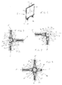
Fig. 1 shows a perspective front view of the main modular element of the prefabricated modular structure according to the invention, constituting a vertical flat wall; -
Fig. 2 shows a plan view of a portion of two main modular elements ofFig. 1 , joined to each other at right angle by means of a first connecting modular element according to the invention; -
Fig. 3 shows a plan view of a portion of three main modular elements ofFig. 1 , joined to each other at right angle by means of a second connecting modular element according to the invention; -
Fig. 4 shows a plan view of a portion of four main modular elements ofFig. 1 , joined to each other at right angle by means of a third connecting modular element according to the invention; -
Fig. 5 shows a perspective front view of three main modular elements joined to each other at right angle, and also joined with a set of four modular elements constituting the floor of the structure according to the invention, and with fifth modular elements constituting a reinforcing structure; -
Fig. 6 shows a side view of a cutaway portion of the reinforcing structure ofFig. 5 , joined with a main modular element according to the invention; -
Fig. 7 shows a side view of the junction between a respective portion of main modular element and of two sixth modular elements forming the horizontal flat roof of the structure according to the invention; -
Fig. 8 shows a perspective front view of the structure formed by the same modular elements ofFig. 5 , and joined with a sixth modular element forming the horizontal flat roof; -
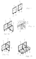
Figs. 9-18 show with a respective perspective front view the assembling phases performed for assembling the different modular elements of a prefabricated modular structure according to the present invention, with a base manufacturing configuration; -
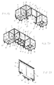
Figs. 19-25 show with a respective perspective front view the assembling phases performed for assembling the different modular elements of the base modular structure ofFigs. 9-18 with the different modular elements of a modular structure with a special configuration, in order to realize rooms with a double dimension than the ones of the base structure; -
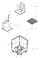
Fig 26, 27 and 28 show with a respective perspective front view a special floor with sink, a special floor with a seating WC, and connected flushing cisterns and safety handles for handicapped persons, as well as a special floor used as shower tray with a relative drainage, which floors are installable both into the base modular structures ofFigs. 9-18 and into the special modular structures ofFigs. 19-25 ; -
Fig. 29 shows a perspective front view of a portion of the base structure of a standard bathroom, installed into a base structure visible in theFigs. 9-18 ; -
Fig. 30 shows a perspective front view of a portion of base structure visible inFigs. 9-18 , into which there are installed the three types of special floors ofFigs. 26, 27 and 28 : -
fig. 31 shows a perspective front view of a portion of the structure ofFig. 30 , with a covering roof of the same. - The present invention refers to a prefabricated modular structure, adapted to be used for manufacturing buildings of various kind during emergency situations, like schools, hospitals, temporary assistance centres, and similar inhabited structures, with different and variable configurations as desired, and with reduced times for assembling and installing and disassembling the various components elements of the same structure. This prefabricated modular structure is realized with the component elements that will be described, having standard dimensions such to allow to transport without problems all the component elements onto transports means of any kind, like wagons, trucks, containers and the like, the structure being also adapted to be assembled and disassembled into different places and positions.
- In the Figures that will be illustrated, there are described in detail all the types of component elements composing the structure referred to, that are of the modular type and may be assembled and disassembled to each other by means of fixing means of traditional type, for forming prefabricated structures with different and variable configurations, as well as there are described some examples of constructive configurations of the structures that are realized by utilizing these component elements.
- The modular component elements used for realizing the prefabricated structure are the following:
- one main modular element 5 (see
Fig. 1 ), constituting the load bearing structure of the structure, - a first connecting modular element 6 (see
Fig. 2 ), for removably connecting two mainmodular elements 5, - a second connecting modular element 7 (see
Fig. 3 ), for removably connecting three main modular elements (5), - a third connecting modular element 8 (see
Fig. 4 ), for removably connecting four main modular elements (5), - a fourth modular elements 9 (see
Fig. 5 ), constituting the floor of the present structure, - a fifth modular element 10 (see
Fig. 5 ), constituting a reinforcing structure, - a sixth modular element 11 (see
Fig.7 ), constituting the horizontal flat roof of the structure. - The main
modular element 5 is substantially constituted by a vertical closedflat frame 12 with rectangular shape, forming a wall with the upper and lower horizontal sides that are shorter, and parallel to each other, and with the vertical sides that are parallel to each other. The width of such main element is selected smaller than the internal free width of a standard container ISO of 20 ft, in such a way that the mainmodular element 5 may be housed also into the containers and transported with these latter, whereas the height of the same main element may theoretically be such as to reach the internal free depth of each container (of about 6 meters), but this height is advantageously selected with a smaller size (of about 2,560 meters), in such a way that each container may contain two pallets placed side by side and supporting various main modular elements, and that the internal free height of each assembled module be many times greater than 2,400 meters, that constitutes a correct height for the operation and that complies with the building law relating to the stationary buildings structures of traditional type. Eachwall frame 12 is realized with peripheral metallic walls, that may be full or may also define to each other an internal free space into which there are inserted some insulating panels made of insulating material of traditional type (e.g. polystyrene), that in the example are constituted by twopanels flat frame 12 may also be made hollow into its interior, and without insulating panels, and in such case it provides a reinforcing structure that will be described, or it may provide also through openings through therelative insulating panels frame 12, furthermore, has the upper 15 and lower 16 horizontal sides with the same profile, slightly hollowed for the entire length of the relative side, that in theupper side 15 performs the function of gutter for collecting and draining of rainwater, and in thelower side 16 serves for supporting the floor of the modular structure. In thelower side 16 there are also fixed at least twosupport feet Fig. 1 , in a manner to assure a balanced support of the same frame, and being adjustable in height with micrometric regulation, for a perfect levelling of theframe 12 with respect to the ground. The twovertical sides horizontal sides - The cross-section of the stanchions and the above mentioned functions are visible in
Figs. 2, 3 and 4 that will be described later, and such stanchions may be connected to the adjacent frames respectively with - 1) said first connecting
modular element 6, for the removable connection of two main modular elements 5 (seeFig. 2 ), arranged orthogonally to each other, - 2) with said second connecting
modular element 7, for the removable connection of three main modular elements 5 (seeFig. 3 ), arranged orthogonally to each other, - 3) with said third connecting
modular element 8, for the removable connection of four main modular elements (seeFig. 4 ), arranged orthogonally to each other, - 4) with said fourth modular element 9, constituting the floor of the present structure (see
Figs. 5 and 6 ), the connecting being performed by arranging thestanchions - 5) with said fifth
modular element 10, constituting the reinforcing structure, arranged in a position into contact and aligned with a relative stanchion (seeFig. 5 ), - 6) with said sixth modular element 11, constituting the horizontal flat roof of the structure (see
Figs. 7 and 8 ), arranged orthogonally to the relative stanchion. - Referring to the
fig. 2 , there is now described the first connectingmodular element 6, for joining to each other the twovertical stanchions modular elements 5, into which it is assembled a relativeinsulating panel - Before to describe such a first
modular element 6, it is described each vertical stanchion, that is constituted by ametallic section bar 21 that, in the illustrated example, is shaped with a square cross-section provided with an internalcircular hole 22 for the passage of the rainwater and its conveying downward, and into its side turned inward the mainmodular element 5 thesection bar 21 is lengthened with twoshort projections section bar 21 is shaped with two additional short projections (not shown), that are parallel and close to each other and are provided for the connection of the same section bar with each first connectingmodular element 6, and these additional projections are bored in positions correspondent to each other, for allowing the passage ofcorrespondent bolts 25 for fixing the relative connectingelement 6. Of course, each vertical stanchion may be shaped also with conformations different from that described, provided that it always performs the same function, thus without departing from the protection sphere of the present invention. - In turn, the first connecting
element 6, named also column, is substantially constituted by a firstcurved element 26 and by a secondcurved element 27 both having a relativecurved portion 28 and 29 that are parallel and spaced away to each other, of which the firstcurved element 26 has a radius of curvature greater than that one of the secondcurved element 27, and both said curved elements are extended in the vertical direction for the entire height of each stanchion. The firstcurved element 26 and the secondcurved element 27 are lengthened with relative short horizontal rectilinear end portions (not indicated), entering for a determined depth into the hollow (not shown) of the adjacent vertical side of the relativemain element 5, and both the end portions of each first and secondcurved element section bar 21 of a relative vertical stanchion. Furthermore, near one of the horizontal end portions of such first and secondcurved elements flat flange 30, orthogonal to the same end portions and adapted to be arranged into external contact to the vertical side of amain element 5, for all the width of the same side, whereas near the other one of the horizontal end portions of such first and secondcurved elements flat flange 31, orthogonal to the same end portions and identical to the previous flange, and adapted to be arranged into external contact to the vertical side of anothermain element 5, orthogonal to the previousmain element 5, and for the entire width of the same side. The twoflat flanges curved element 26 and secondcurved element 27, in a such position that, when these curved elements are secured to the relative vertical stanchions 21 (seeFig. 2 ) of the twomain elements 5 arranged orthogonal to each other as visible from this Figure, the correspondent curvedportion 28 and 29 of these curved elements be extended for the entire distance existing between the twoflat flanges - The junction between the two
main elements 5 arranged orthogonal to each other, as shown inFig. 2 , is effected by levelling at first the horizontal lower sides of suchmain elements 5 with respect to the ground, by regulating the height of thesupport feet fixing bolt 25 into the through holes coinciding to each other of both the horizontal end portions of said first and secondcurved elements vertical section bar 21 of the stanchions, and moreover by introducing someU-shaped bars 32 into the space existing between both the end portions of said first and secondcurved elements - The object of
such U-shaped bars 32 is to lock theheads 33 of thefixing bolts 25, adjacent to the same bars, thereby preventing the bolts from being unscrewed from the outside. - Referring to the
Fig. 3 , it is now described the second connectingmodular element 7, for joining to each other three mainmodular elements 5, of which two elements (that in the Figure are the vertically arranged elements 5) are arranged aligned to and spaced away from each other by the second connectingelement 7, and the third element of which (in the Figure is the horizontally arranged element 5) is oriented orthogonal to the previousvertical elements 5, and also in this case in the mainmodular elements 5 it is assembled a relative insulating panel. - Such second connecting
element 7 is provided for joining to each other the section bars adjacent to each other of eachmain element 5, which section bars are identical and comprise the same connection devices of the ones previously described (that is afixing bolt 25 and a U-shaped bar 32), the connecting element referred to being substantially constituted by twocurved elements 27 identical to the previously describedcurved element 27, of which a firstcurved element 27 is provided for joining thesection bar 21 of one of the vertical main elements 5 (in this case, of the upper one element in theFig. 3 ) with thesection bar 21 of the horizontalmain element 5, and a secondcurved element 27 is symmetrical and aligned with respect to the firstcurved element 27, and is provided for joining thesection bar 21 of the horizontalmain element 5 with thesection bar 21 of the thirdmain element 5 arranged vertical (in this case, of the lower element in theFig. 3 ). - In this case, the first
curved element 27 is joined to a shortflat flange 34, placed near one end portion of the same curved element and adapted to be arranged into external contact to the vertical side of the vertical and uppermain element 5, and such firstcurved element 27 is also joined to an additional shortflat flange 35, placed near the other end portion of the same curved element, and adapted to be arranged into external contact to the vertical side of the horizontalmain element 5. In turn, the secondcurved element 27 is joined to said additionalflat flange 35, situated near an end portion of the same curved element and adapted to be arranged into external contact to the vertical side of the horizontalmain element 5, and such secondcurved element 27 is also joined to an additional shortflat flange 36, placed near the other end portion of the same curved element and adapted to be arranged into external contact to the vertical side of the other lower verticalmain element 5. - The second connecting
element 7, finally, is constituted by arectilinear portion 37 that in the example ofFig. 3 is arranged vertical, and which is extended in the vertical direction for the entire height of the stanchions, and thisrectilinear portion 37 is joined with theflat flange 34 near an end portion of the same rectilinear portion, and suchrectilinear portion 37 is also joined to the additionalflat flange 36 near the other end portion of the same rectilinear portion. - Referring to the
Fig. 4 , it is now described the third connectingmodular element 8, for joining to each other four mainmodular elements 5, of which two elements (that in the Figure are the vertically arranged elements 5) are arranged aligned to and spaced away from each other by the third connectingelement 8, and the other two elements (that in the Figure are the horizontally arranged elements 5), are oriented horizontally and orthogonally with respect to the first twovertical elements 5, and are also arranged aligned to and spaced away from each other by the same third connectingelement 8, and also in this case a relative insulating panel is mounted onto all said mainmodular elements 5. - Such third connecting
element 8 is provided for joining to each other the section bars adjacent to each other of eachmain element 5, which section bars are identical and comprise the same connecting devices of the ones previously described (that is afixing bolt 25 and a U-shaped bar 32), the connecting element referred to being substantially constituted by twocurved elements 27 identical to and placed as thecurved elements 27, as well as joined to thesame flanges 34, 35e 36 as described in theFig. 3 , and such third connectingelement 8 being also constituted by two additionalcurved elements 27 identical to and placed as the just describedcurved elements 27, however symmetrical and aligned with respect to these latters. In this case, the first one of the additionalcurved elements 27 is joined to a shortflat flange 38, placed near one end portion of the same curved element and adapted to be arranged into external contact to the vertical side of one of the horizontal main elements 5 (in the example ofFig. 4 , of the left-side horizontal main element 5), and such first additionalcurved element 27 is also joined to saidflat flange 34 near the other end portion of the same curved element. In turn, the second one of thecurved elements 27 is joined to theflat flange 38 situated near an end portion of the same curved element and is also joined to saidflat flange 36, situated near the other end portion of the same curved element. - Referring to the
Figs. 5 and 6 , it is now described the fourth connecting modular element 9, constituting the floor of the present structure, which is substantially constituted both by first horizontal and rectilinearmetallic cross-pieces 39, that are identical to and arranged parallel from each other and in the longitudinal direction of different mainmodular elements 5 aligned and joined to each other, and by second horizontal and rectilinearmetallic cross-pieces 40, that are identical to and smaller than thefirst cross-pieces 39, and which are arranged parallel to each other and in the transversal direction of different mainmodular elements 5 aligned and joined to each other, and all the first andsecond cross-pieces lower sides 16 of saidmodular elements 5 aligned and joined from each other, with such an arrangement as to be able to house somehorizontal floor plates 41 identical and arranged horizontally aligned to each other, forming the walkable floor. Each first longitudinalhorizontal cross-piece 39 and each second transversal horizontal cross-piece element 40 (seeFig. 6 ) has an upper fixed section bar 42 and two movablelower shells 43, of which the upper fixed section bar 42 has a cross-section shaped almost of square shape, and is extended downward with two short and thinvertical side walls lower shells 43 are symmetrical to each other and are formed each by a short upper vertical portion 48 and a C-shapedlower portion 49, wherein the C-shaped portion of eachshell 43 is bored at determined intervals for its whole length, at positions that are coinciding with those ones of the holes of theside walls correspondent fixing bolt 50, the head of which (not shown) is arranged externally to the shell wall and the stem of which (not shown) is at first inserted into a correspondent hole of the section bar side wall respectively opposite, and then is tighten by means of a nut (not shown) to such side wall. The purpose ofsuch shells 43 is to support the relative side edge of ahorizontal floor plate 41, and in the indicated example there are shown twofloor plates 41 aligned and spaced away to each other by thecross-piece 39, the side edges 51 and 52 of which are laid on to arelative shell 43 and supported by the same. - In the
fig. 6 it is noted that the fourth connecting modular element 9 comprises also two additional lowermovable shells 53 and 54, that are identical to such movablelower shells 43, which additional shells are applied to the short and thin sidevertical walls vertical walls lower side 16 of each mainmodular element 5, each shell of which is bored for the passage of a fixingbolt 57, that is inserted also through correspondent through holes (not shown) provided at determined intervals for the whole length ofsuch side walls relative fixing bolt 57, for laying therelative side edge 58 of thefloor plate 41 thereon, and for supporting the same plate, whereas the other shell 43 (the right side one) is shown without holes, since in this case there aren't provided floor plates at the other part of the mainmodular element 5. Should the floor plates be applied also in the other part of themain element 5, instead of the not bored shell it is arranged a bored shell (not shown) provided with the relative fixing bolt (also not indicated). For applying eachfloor plate 41 with a determinate size in to the relative housing position of a floor support structure obtained as described, it is then sufficient at first to loose the fixing bolts which are foreseen, and then to displace each shell in the horizontal direction up to the position suitable to support the correspondent side edge of the floor plate with this size. Finally, on to the shells there is applied the relative floor plate and the shells are then secured in this position by clamping their fixing bolts to the relative side walls of the same plate. - Referring now to the
fig. 5 , it is noted that in this example the visible modular structure is constituted both by twomain elements 5 assembled aligned to each other, and into which it is inserted a relative insulatingpanel modular element 5 internally empty (namely, without insulating panels) that is secured orthogonally on to the front of the above-describedmain elements 5, and by alongitudinal cross-piece 39 and by twotransversal cross-pieces 40, supporting thelongitudinal cross-piece 39, and each one which is secured as it will be described to the centre line of the relativemain element 5. Such alongitudinal cross-piece 39 is supported also onto the ground by means ofsupport feet 59 adjustable in height and identical to thefeet main element 5, which are secured along thecross-piece 39 at determined intervals (in the example, there are shown four support feet 59), and the free end portions of thelongitudinal cross-piece 39 are bolted, through head plates (not shown), to the centre line respectively of a first and second pair of main elements (not shown), assembled aligned to each other, that are fixed in a position orthogonal to the relativevertical sides main elements 5. In turn, eachtransversal cross-piece 40 is not provided with lower support feet, and is supported with a free end portion thereof by a head plate (not shown), that is bolted to the centre line of thelower side 16 of the two relativemain elements 5, and with the other free end portion thereof is supported by another head plate (not shown), that is bolted to the centre line of the lower side of two additional main elements (not shown), arranged aligned to each other, which are secured orthogonally to thevertical side 20 of theempty element 5, in a position parallel to the preceding twomain elements 5 visible in the Figure. - In turn, the
longitudinal cross-piece 39 is supported by thetransversal cross-pieces 40 thanks to correspondent hollows (not shown) provided in the central zone of the transversal cross-pieces, into which hollows thelongitudinal cross-piece 39 is inserted. - Furthermore, in the
Fig. 6 the twomain elements 5 aligned to each other are joined to the othermain element 5 orthogonally thereto by means of the second connectingelements 7 described with reference to theFig. 3 . Finally, the floor structure realized by assembling to each other the above-described component elements, in the considered example forms a set of squared painted backgrounds (not shown), into which there are inserted relative floor plates 41 (not shown in the Figure), arranged at the same level, which are then locked in position as described with reference to theFig. 6 . Referring always to theFig. 5 , it is noted that the emptymain element 5 is reinforced with a reinforcing structure constituted by the fifthmodular element 10, and formed by avertical bar 60, that is inserted into the empty space of amain element 5 and applied into contact with the relativevertical side 19 of this main element, to which it is opportunely secured. Such a vertical bar is also fixed in the same manner to the othervertical side 20 of thismain element 5, that as already described is fixed to two additional main elements arranged parallel to the twomain elements 5 visible in this Figure, and this additional vertical bar and the additional main elements are not represented here for simplicity. - Referring now to the
Figs. 7 and 8 , it is now described the sixth modular element 11 constituting the flathorizontal roof 61 of the present modular structure, that is arranged and fixed as it will be described on to both the horizontal and hollowedupper side 15 and the vertical section bars 21 of the relative vertical stanchions of themain elements 5 of the same structure. - Each horizontal
flat roof 61 is dimensioned for adapting itself on to at least two upper hollowed sides 15 of twomain elements 5 assembled to each other, and to be fixed to the same ones as it will be soon described. In thefig. 7 , there may be noted two horizontalflat roofs 61 that are arranged and fixed with a side edge thereof on to a portion of an upper horizontal and hollowedside 15 of amain element 5, whereas with the other side edge thereof suchflat roofs 61 are arranged and fixed in the same manner on to the other upper horizontal and hollowed sides (not shown) of additional main elements (also not shown), and with this arrangement theflat roofs 61 are aligned to each other. In each side edge of each one of theflat roofs 61 it is applied a fixing flange 62, shaped with a short and thin horizontal rectilinear portion 63, adapted to be arranged into contact to the upper surface of the side edge of theroof 61, and such a flange horizontal portion is bent for forming a first short and thinvertical portion 64, adapted to be arranged into contact to theexternal side surface 65 of the roof side edge, and for forming also a second short and thinvertical portion 66 directed downward, which is arranged parallel to the firstvertical portion 64 and is joined to the same and it is extended downward in such a way that, when the flange 62 is applied in position, it may enter slightly the hollow 67 defined in the upper hollowedside 15 of the main element. Such a first flangevertical portion 64, finally, is still bent downward for forming a short and thin horizontal portion (not shown) and a short and thin lower vertical portion (also not shown), ending with an end portion bent like a hook 68. The fastening in position of each side edge of theflat roof 61 with the relativevertical section bar 21 is then effected by arranging at first the horizontal portion 63 and the firstvertical portion 64 of the flange respectively to the upper surface and to theexternal side surface 65 of the roof side edge, in a manner that the second vertical portion of theflange 66 enters partially the hollow 67 and that the lower horizontal portion of the flange be arranged below the lower surface of the roof side edge and that the lower vertical portion of the flange be spaced away laterally from said hollowedhorizontal side 15. At this point, each roof side edge is laid partially on to the hollowedhorizontal side 15 and the fastening and locking in position of the roof is obtained by means of said flange 62 and a sliding bracket 69, formed by a rectilinear vertical portion 70, the upper end portion 71 of which shaped as a hook is adapted to be hooked with the hook 68, and which is also joined to a shorthorizontal portion 72, adapted to abut in the lower side on to the upperhorizontal side 15, and the vertical portion 70 of the bracket 69 is also bored for inserting abolt 73, onto which a wing head 74 may be screwed and unscrewed. - Then, for locking in position the side edge of the
roof 61, such a bracket 69 is hooked with its hook 71 into the hook 68 of the flange 62 and the horizontal portion ofbracket 72 is pushed in abutment in the lower part on to the upper hollowedside 15, thereafter said wing head 74 is screwed onto thebolt 73 up to the bracket 69 is firmly tightened to said flange 62 and the upper hollowedside 15. Then, under the condition, as it is visible in theFig. 7 , thevertical portions 66 of the two flanges 62 are spaced away to each other, by defining a vertical passage (not shown) into which rainwater penetrate, that fall into the gutter hollow 67 of thehorizontal side 15, from which they are conveyed into the inlet of the relative gutter descending element of each vertical side of themain element 5, and are therefore drained onto the ground. - In the
Fig. 8 it is shown a modular structure formed by the same component elements ofFig. 5 , comprising thefloor plates 41 and the roofs 61 (of which in the Figure only aroof 61 is visible), and these component elements are joined to two additionalmain elements 5 arranged parallel to the emptymain element 5, of which the left side main element has on opening 75 for entering into the same modular structure. - In the
Figs. 9-18 there are shown the assembling phases performed for assembling the different modular elements of a modular structure realized in the base building configuration, identical to and with the same component elements described in theFigs. 5-8 . In the phase of theFig. 9 , there are noted the twomain elements 5 with inserted insulatingpanels relative support feet element 7, described with reference to theFig. 3 . - In the phase of the
Fig. 10 , to the twomain elements 5 joined to each other it is added, perpendicular thereto, the third emptymain element 5, in the interior of which the reinforcingvertical bar 60 is applied, and, before being approached and bolted to the other twomain elements 5, this thirdmain element 5 must be aligned to the other twomain elements 5 and put at the horizontal level by means of a level (not shown). - The
Fig. 11 shows in detail the interconnection between the threemain elements 5, in to which it is noted theU-shaped bar 32 locking the head of the fixing bolts (not indicated), by preventing the unscrewing from the external and consequently by securing the entire structure. In the Figure there are noted also the horizontalupper sides 15 of the three main elements, the gutter hollows 67 of which are all communicating with the descending gutter hollows of the relative vertical sides of such main elements, for collecting therefore the rainwater and drain it onto the ground. - In the assembling phase of the
Fig. 12 , there are noted the threemain elements 5 joined to each other, thereby determining a stable structure constituting the base structure, to which the other component elements of the entire structure may be progressively connected. Since this base structure is stable, it is convenient and advisable to verify on to it the perfect horizontality of its component elements, by acting on to the supporting and levellingfeet - In the phase of the
Fig. 13 , it is noted that to the main elements of this base structure there are added and bolted all the othermain elements 5, that may be made of the most different forms (empty, full, full with door, full with window, or with any kind of windows and door frames), anyway always fully interchangeable to each other. - In the phase of the
Fig. 14 , there are put the stiffening elements of the floor and for each painted background it is inserted a greaterlongitudinal cross-piece 39 and two smallertransversal cross-pieces 40, thereby subdividing the base grid of the modules in and under-grid having a half width (about of 1 meter), into which there will be then inserted and fixed thefloor plates 41. - In the phase of the
Fig. 15 , in the structure obtained as in theFig. 14 there are inserted by a fixed joint and locked all thefloor plates 41. - In the
Fig. 16 it is shown in detail the corner of the structure formed by twomain elements 5 joined to each other by a first connectingmodular element 6, of which there may be noted the first and the secondcurved element - In the phase of the
Fig. 17 , it is put the first of twoflat roofs 61 which will be locked on to the above described underlying structure. - In the phase of the
Fig. 18 , also the secondflat roof 61 has been put, thereby completing the base modular structure, of which it is noted also anopening 76 for assembling the door. - In the example referred to, such a base modular structure of having the dimensions of two base modules has the external dimensions of about 2,400 meters x 4,700 meters and a height of about 2,650 meters. All the component elements of this structure may be inserted into one pallet with a length of 2,852 meters, width of 2,280 meters and height of 1,190 meters, which may be introduced into a standard container ISO of 20 feet, into which therefore there may be introduced four above-mentioned pallets, with an obtainable total volume equal to about four times the transported volume.
- Referring now to the
Figs. 19-24 , it is shown in which manner the above-described base modular structures may be integrated with some special modules that will be described hereinafter, which are adapted to allow to realize some rooms of a dimension double than that of the base module, namely with ports of about m. 4,500 without columns and/or intermediate vertical structures. - In the
Fig. 19 , there are shown as example two base modular structures that are joined to each other by a special module, which base structures are formed the one by a module with sevenmain elements 5 and the other one with a module formed by fourmain elements 5. These two base modular structures are spaced away to each other by two additionalmain elements 5, that may be made of any type (in the example, they are formed by two main elements with an empty internal space), and which are arranged aligned to each other and joined to the above mentioned base modular structures, whereas into the intermediate spans the port of the two base modular structures is covered by the special structure. - As it is visible in
Fig. 21 , the special structure is substantially constituted by twostanchions vertical side 79 and anhorizontal side 80 provided with itsown support foot 81 adjustable in height, and by a lowerhorizontal beam 82 and an upperhorizontal beam 83, of which thelower beam 82 has the same cross-section of thehorizontal side 80 of each stanchion and the same length of the distance existing between the opposite end portions of the relativehorizontal sides 80, thereby for being joined to the same horizontal sides. Moreover, such alower beam 82 is provided withlower support feet 81 adjustable in height, identical to thesupport feet 81 of thehorizontal side 80 of each stanchion, and adapted to be arranged onto the ground in a position aligned to and spaced away with respect to the previous twosupport feet 81, when saidlower beam 82 is joined to said horizontal sides. In turn, the upperhorizontal beam 83 has the same cross-section of the upperhorizontal sides 15 of themain elements 5 and a length double than the one of eachmain element 5, thereby for being arranged on to the twomain elements 5 joined to each other, to which such anupper beam 83 is then joined, together with the relative stanchions, through the second connectingmodular elements 7. - In the
Fig. 22 it is shown the complete special structure, whereas in theFig. 19 there are shown the above specified two base modular structures, into which such a special structure has not yet been mounted, and in theFig. 20 it is shown thelower beam 82 of the special structure assembled to the two above described two base modular structures. - In the
Fig. 25 it is noted the complete special structure of theFig. 22 , together with anadditional beam 86, that is joined orthogonally to said upperhorizontal beam 83 and has the same length of the upperhorizontal sides 15 of themain elements 5 of said two base modular structures and the same cross-section of these sides, thereby for supporting theroof 61. - In the
Fig. 25 it is also visible an additionallower beam 87, that is fixed with an end portion thereof below the lower sides of the twomain elements 5 joined to each other by said upperhorizontal beam 83, in the orthogonal direction and in the centre line of the same main elements, and this additionallower beam 87 has the same length and the same cross-section of said secondsmaller cross-pieces 40, and twosupport feet lower beam 87, which are identical to the previous ones. In this manner, as visible in theFig. 20 , wherein it is shown the lowerhorizontal beam 87 of theFig. 25 only, thelower beam 87 is joined both to afirst cross-piece 39 , the end portions of which are joined to the relativemain elements 5 as it is described above, and to threesecond cross-pieces 40, arranged parallel to thelower beam 87, and secured with the end portions thereof at one side to saidlower beam 82 and at the other side below to lower sides of the twomain elements 5, that are joined to each other by asuitable support structure 88, inserted into the upper part of the relative vertical stanchion, and adapted to support a side of theroof 61. In this way, between thecross-piece elements beams relative floor plates 41. - In the
Fig. 23 it is noted that thefloor plates 41 have been inserted into the respective positions, by forming thereby the horizontal floor, and that the upperhorizontal beam 83 has been mounted in position, for the subsequent arrangement of all theroofs 61 on to the upperhorizontal beams main elements 5, as visible in theFig. 24 . - In the
Figs. 26-31 there are shown some special elements for bathroom, that may be combined with the modular structures according to the present invention. - In the
Fig. 26 it is shown aspecial floor 89 withsink 90, arranged onto afurniture 91 containing both the boiler and the delivering pump and all the other instruments allowing the operation of the sanitary service. Thesink 90 comprises also thetelescopic arm 92 and theshowerhead 93. - In the
Fig. 27 it is shown thespecial floor 94 with toilet withseat 95 and, in addition to the sanitary service of toilet, it comprises the connected flushingcistern 96, in addition to the safety handles 97 for handicapped persons. In theFig. 28 it is shown thespecial floor 98 intended to be used as shower tray and relative drainage. In theFig. 29 it is shown the base structure of a standard bathroom, constituted by base modules formed bymain elements 5 with full wall, or main elements with door opening 76, connected to each other by a first connectingmodular element 6 and bolted with the U-shaped safety bars 32. The floor reinforcing structure is constituted by firstgreat cross-pieces 39 and by secondsmall cross-pieces 40. - In the
Fig. 30 it is shown the load bearing structure of theFig. 29 , into which there are inserted the special floor elements and, in particular, thespecial floor 89 withsink 90, thespecial floor 98 with shower and thespecial floor 94 with toilet withseat 95. Only after having connected to each other the delivery sides and the drainages of the above mentioned special floors, it is possible to position also the fourth floor element constituted by astandard floor element 41. - Finally, in the
Fig. 31 is shown the same load bearing structure with the special elements of theFig. 30 with an overlyingstandard roof 61 secured in the already described way to the underlying structure.
Claims (13)
- Prefabricated modular structure, adapted to be used for manufacturing buildings of various kind during emergency situations, like schools, hospitals, temporary assistance centres, and similar inhabited structures, with different and variable configurations, and with reduced times for assembling and installing and disassembling the various components elements of the same structure, characterized in that to comprise:- one main modular element (5), constituting the load bearing structure of the structure,- a first connecting modular element (6), for removable connecting two elements (5),- a second connecting modular element (7), for removable connecting three main modular elements (5),- a third connecting modular element (8), for removable connecting four main modular elements (5),- a fourth modular elements (9), constituting the floor of the present structure,- a fifth modular element (10), constituting a reinforcing structure,- a sixth element (11), constituting the horizontal flat roof of the structure,said first main modular element (5) being constituted by a vertical flat frame (12) with rectangular shape, forming a wall with the upper and lower horizontal sides that are shorter, and parallel to each other, and with the vertical sides that are parallel to each other, and with such a width as to be able to be housed into standard containers too, for being transported by these latter, whereas the height of said main element (5) being such as to be able to arrive up to the internal free depth of each container, each wall frame (12) being realized with peripheral metallic walls, that may be full or may be also define to each other an internal free space into which there are inserted some insulating panels (13, 14) made of insulating material of traditional type (e.g. polystyrene), each flat frame (12) being also realizable with a hollow into its interior, and without insulating panels, said wall frame (12) being also realizable with through openings through the relative insulating panels (13, 14), with the shape of doors and windows, and finally being provided at its lower part with support feet (17, 18) adapted to be arranged onto the ground and/or onto suitable support platforms, said vertical flat frame (12) being adapted to be joined removable to one or both its vertical sides, by means of fixing means, to a correspondent vertical side of a vertical frame (12) adjacent thereto, both by means of said first connecting modular elements (6), for constituting a first base module formed by four main elements (5), and of second connecting modular elements (7), without or with said third connecting modular elements (8), for constituting a second base module formed by two or more first base modules joined removable to each other by means of fixing means, wherein each one of said first and second base module is also adapted to be joined removable, by fixing means, with its lower horizontal sides, to said fourth floor modular element (9), for forming the floor that then is covered with horizontal floor plates (41), and is also adapted to be joined removable with its upper sides, by means of fixing means, to said sixth modular elements (11) constituting the flat horizontal roof, for forming the same flat roof, and being finally adapted to be joined removable, by means of fixing means, also to one or more special modules, said first and second base module and said special module being adapted to be joined removable to each other, by means of fixing means, with different and variable configurations, for forming the desired modular structure.
- Prefabricated modular structure according to claim 1, characterized in that all the vertical frames (12), whichever type they are, are completely interchangeable to each other, thereby for obtaining modular structures with identical or different configurations, each frame (12), furthermore, having the upper (15) and lower (16) horizontal sides with the same profile, slightly hollowed for all the length of the relative side, that into the upper side (15) performs the function of gutter for collecting and draining of rainwater, and in the lower side (16) serves for supporting the floor of the modular structure, and that said support feet (17, 18) secured into the lower side (16) are also adjustable in height with a micrometric adjustment, for a perfect levelling of the frame (12) with respect to the ground , and that the two vertical sides (19, 20) of any type of frame, acting like stanchions, have the same hollowed profile for a determined depth for all the height of the relative side and have reduced thickness with respect to the upper and lower horizontal sides (15, 16) and perform, in addition to the load bearing, also the function of gutter descending element, for draining the rainwater on to the ground, as well as of interconnecting element among the frames (12).
- Prefabricated modular structure according to claim 2, characterized in that each of said vertical stanchion (19, 20) is constituted by a metallic section bar (21) provided with an internal circular hole (22) for the passage of the rainwater and its conveying downward, and into its side turned inward the main modular element (5) the section bar (21) is lengthened with two short projections (23, 24), that are parallel and spaced away to each other for housing and securing the correspondent end portion of the relative insulating panel, whereas into the side opposed to the above-mentioned side the section bar (21) is shaped with two additional short projections, that are parallel and close to each other and are provided for the connection of the same section bar with each first modular connecting element (6), and these additional projections are bored in positions that are correspondent to each other, for allowing the passage of correspondent bolts or similar means (25) for fixing the relative connecting element (6).
- Prefabricated modular structure according to claim 3, characterized in that said first connecting element (6), named also column, is substantially constituted by a first curved element (26) and by a second curved element (27) both having a relative curved portion (28, 29) that are parallel and spaced away to each other, of which the first curved element (26) has a radius of curvature greater than that of the second curved element (27), and both said curved elements are extended in the vertical direction for the entire height of each stanchion, and are lengthened with relative short horizontal rectilinear end portions, entering for a determined depth into the hollow of the adjacent vertical side of the relative main element (5), and both end portions of each first and second curved element (26, 27) are bored in positions coinciding with the positions of the relative through holes of the additional projections of the section bar (21) of a relative vertical stanchion, and near one of the horizontal end portions of such first and second curved elements (26, 27) there is also provided integral a short flat flange (30), orthogonal to the same end portions and adapted to be arranged into external contact to the vertical side of a main element (5), for all the width of the same side, whereas near the other of the horizontal end portions of such first and second curved elements (26, 27) there is provided integral an additional short flat flange (31), orthogonal to the same end portions and identical to the previous flange, and adapted to be arranged into external contact to the vertical side of another main element (5), orthogonal to the previous main element (5), and for the entire width of the same side, said two flat flanges (30, 31) being secured onto the relative first curved element (26) and second curved element (27), in a such position that, when these curved elements are secured to the relative vertical stanchions (21) of the two main elements (5) arranged orthogonal to each other, the correspondent curved portion (28, 29) of these curved elements is extended for all the distance existing between the two flat flanges (30, 31), in a manner to not leave free spaces between the same flanges.
- Prefabricated modular structure according to claim 4, characterized in that the junction between two main elements (5) arranged orthogonal to each other is effected by levelling at first the horizontal lower sides of such main elements (5) with respect to the ground, by regulating the height of said support feet (17, 18), and then by introducing a fixing bolt or the like (25) into the through holes coinciding to each other of both the horizontal end portions of said first and second curved elements (26, 27) and the additional projections of each vertical section bar (21) of the stanchions, and moreover by introducing some U-shaped bars (32) into the space existing between both the end portions of said first and second curved elements (26, 27) and the opposite flat side of the same vertical section bar, in such a way that such U-shaped bars (32) lock the heads (33) of the fixing bolts (25), adjacent to the same bars, thereby preventing the bolts from being unscrewed from the outside.
- Prefabricated modular structure according to claim 5, characterized in that said second connecting modular elements (7), is provided for joining orthogonally to each other the section bars identical and adjacent to each other of each main element (5), and is substantially constituted by two curved elements (27) identical to the above-mentioned curved element (27), of which a first curved element (27) is provided for joining orthogonally the section bar (21) of one of the main vertical elements (5) with the section bar (21) of another main vertical element (5), and a second curved element (27) is symmetrical and aligned with respect to the first curved element (27), and is provided for joining orthogonally the section bar (21) of the other main vertical element (5) with the section bar (21) of an additional main element (5) arranged vertical, said first curved element (27) being joined to a short flat flange (34), placed near one end portion of the same curved element and adapted to be arranged into external contact to the vertical side of the one main vertical element (5), and such first curved element (27) being also joined to an additional short flat flange (35), placed near the other end portion of the same curved element, and adapted to be arranged into external contact to the vertical side of the other main element (5), the second curved element (27) being also joined to said additional flat flange (35), placed near an end portion of the same curved element and adapted to be arranged into external contact to the vertical side of the other main element (5), and such second curved element (27) being also joined to an additional short flat flange (36), placed near the other end portion of the same curved element and adapted to be arranged into external contact to the vertical side of the additional vertical main element (5), said second connecting element (7) being finally constituted by a rectilinear portion (37) that is extended in the vertical direction for the entire height of the stanchions, and which is joined with an end portion thereof to said flat flange (34), and moreover with another end portion thereof to said additional flat flange (36).
- Prefabricated modular structure according to claim 6, characterized in that said third connecting modular element (8) is adapted to join orthogonally to each other four main modular elements (5), of which two elements are arranged aligned and spaced away to each other from the third connecting element (8), and the other two elements are orthogonal to the first two vertical elements (5), and are also arranged aligned and spaced away to each other from the same third connecting element (8), said third connecting element (8) being substantially constituted by two of said curved elements (27) joined to the same flanges (34, 35, 36), and being also constituted by two additional curved elements (27) symmetrical and aligned with respect to said curved elements (27), of which the first one of the additional curved elements (27) is joined to a short flat flange (38), placed near one of its end portions and adapted to be arranged into external contact to the vertical side of one of the other two main elements (5), and such first additional curved element (27) is also joined to said flat flange (34) near the other end portion thereof, whereas the second one of the additional curved elements (27) is joined to said flat flange (38) situated near an end portion thereof, and is also joined to said flat flange (36), situated near the other end portion thereof.
- Prefabricated modular structure according to claim 7, characterized in that said fourth connecting modular element (9), constituting the floor of the present structure, is substantially constituted both by first horizontal and rectilinear metallic cross-pieces (39), that are identical and arranged parallel to each other and in the longitudinal direction of different main modular elements (5) aligned and joined to each other, and by second horizontal and rectilinear metallic cross-pieces (40), that are identical and smaller than the first cross-pieces (39), and which are arranged parallel to each other and in the transversal direction of different main modular elements (5) aligned and joined to each other, and all said first and second cross-pieces (39, 40) are joined to each other and with the lower sides (16) of said modular elements (5) aligned and joined to each other, with such an arrangement as to be able to house horizontal floor plates (41) identical and arranged horizontally aligned to each other, forming the walkable floor, wherein each first longitudinal horizontal cross-piece (39) and each second transversal horizontal cross-piece element (40) has an upper fixed section bar (42) and two movable lower shells (43), of which the upper fixed section bar (42) is extended downward with two short and thin vertical side walls (44, 45), parallel and spaced away to each other, and bored at determined intervals for the whole length of the same section bar, and the movable lower shells (43) are symmetrical to each other and are formed each by an upper vertical short portion (48) and a C-shaped a lower portion (49), wherein the C-shaped portion of each shell (43) is bored at determined intervals for its entire length, at positions that are coinciding with those of the holes of the side walls (44, 45) of the section bar (42), for allowing the passage of a correspondent fixing bolt or the like (50), the head of which is arranged externally to the shell wall and the stem of which is at first inserted into a correspondent hole of the section bar side wall respectively opposite, and then is tighten by means of a nut to such side wall, said shells (43) being adapted to support the relative side edge of a horizontal floor plate (41).
- Prefabricated modular structure according to claim 8, characterized in that said fourth connecting modular element (9) comprises also two additional lower movable shells (53, 54), that are identical to such movable lower shells (43), which additional shells are applied to the short and thin vertical walls (55, 56), which are identical to the preceding vertical walls (44, 45) and are extended downward from the lower side (16) of each main modular element (5), each shell of which is bored for the passage of a fixing bolt or the like (57), that is inserted also through correspondent through holes provided at determined intervals for the whole length of such side walls (55, 56), for laying the relative side edge (58) of the floor plate (41) thereon, and for supporting the same plate.
- Prefabricated modular structure according to claim 9, characterized in that said fifth modular element (10) is formed by at least a vertical bar (60), adapted to be inserted into the empty space of a main empty element (5) and to be applied into contact with a relative vertical side (19) of this main empty element, for reinforcing this latter.
- Prefabricated modular structure according to claim 10, characterized in that said sixth modular element (11), constituting the flat horizontal roof (61) of the present modular structure, is adapted to be arranged and fixed with its side edges on to both the horizontal and hollowed upper sides (15) and the vertical section bars (21) of the relative vertical stanchions of the main elements (5) of the same structure, a fixing flange (62) being applied into each side edge of each flat roof (61), which flange is shaped with a short and thin horizontal rectilinear portion (63), adapted to be arranged into contact to the upper surface of the side edge of the roof (61), and such flange horizontal portion being bent for forming a first short and thin vertical portion (64), adapted to be arranged into contact to the external side surface (65) of the roof side edge, and for forming also a second short and thin vertical portion (66) directed downward, which is arranged parallel to the first vertical portion (64) and is joined to the same and it is extended downward in such a way that, when the flange (62) is applied in position, it may penetrate slightly into the hollow (67) defined in the upper hollowed side (15) of the main element (5), such first flange vertical portion (64), finally, being still bent downward for forming a short and thin horizontal portion and a lower short and thin lower vertical portion, ending with an end portion bent like a hook (68), the fastening in position of each side edge of the flat roof (61) with the relative vertical section bar (21) being effected by arranging at first the horizontal portion (63) and the first vertical portion (64) of the flange (62) respectively to the upper surface and to the external side surface (65) of the roof side edge, in a manner that the second vertical portion of the flange (66) penetrates partially into the hollow (67) and that the lower horizontal portion of the flange be arranged below the lower surface of the roof side edge and that the lower vertical portion of the flange be spaced away laterally from said hollowed horizontal side (15), each roof side edge being laid partially on to the hollowed horizontal side (15) and the fastening and locking in position of the roof being obtained by means of said flange (62) and a sliding bracket (69), formed by a rectilinear vertical portion (70), the upper end portion (71) of which shaped as a hook is adapted to be hooked with the hook (68), and which is also joined to a short horizontal portion (72), adapted to abut in the lower side on to the upper horizontal side (15), and the vertical portion (70) of the bracket (69) being also bored for inserting a bolt (73), onto which a wing head (74) may be screwed and unscrewed, and characterized in that for locking in position the side edge of the roof (61), said bracket (69) is hooked with its hook (71) into the hook (68) of said flange (62) and the horizontal portion of bracket (72) is pushed in abutment in the lower part on to the upper hollowed side (15), thereafter said wing head (74) is screwed onto the bolt (73) up to the bracket (69) is firmly tightened to said flange (62) and the upper hollowed side (15), under the condition in that the vertical portions (66) of the two flanges (62) are spaced away to each other, by defining a vertical passage into which rainwater penetrate, that fall into the gutter hollow (67) of the horizontal side (15), from which they are conveyed into the inlet of the relative gutter descending element of each vertical side of the main element (5), and are therefore drained onto the ground.
- Prefabricated modular structure according to claim 11, characterized by special modules adapted to be integrated with at least two of said first and/or second base module, and which are adapted to allow to realize rooms with double size of the base module, namely with ports preferably of about m. 4,500 without columns and/or intermediate vertical structures, each special module being substantially constituted by two stanchions (77, 78) identical to each other, each with a L-shape with a vertical side (79) and a horizontal side (80) provided with own support foot (81) adjustable in height, and by a lower horizontal beam (82) and a upper horizontal beam (83), of which the lower beam (82) has the same cross-section of the horizontal side (80) of each stanchion and the same length of the distance existing between the opposite end portions of the relative horizontal sides (80), for being therefore joined to the same horizontal sides, said lower beam (82) being also provided with lower support feet (81) adjustable in height, identical to the support feet (81) of the horizontal side (80) of each stanchion, and adapted to be arranged onto the ground in a position aligned and spaced away with respect to previous two support feet (81), when said lower beam (82) is joined to said horizontal sides, said upper horizontal beam (83) having the same cross-section of the upper horizontal sides (15) of the main elements (5) and a length double than that of each main element (5), for being therefore arranged on to the two main elements (5) aligned and joined to each other, that connect said first and/or second base modules, and to which such upper beam (83) is then joined, together with the relative stanchions, through said second connecting modular elements (7), each special module being also constituted by an additional upper beam (86), that is joined orthogonally to said upper horizontal beam (83) and has the same length of the upper horizontal sides (15) of the two main elements (5) of said first and/or second base modules and the same cross-section of these base modules and the same cross-section of these sides, thereby for supporting the roof (61), each special module being finally constituted by an additional lower beam (87), that is fixed with its an end portion below the lower sides of the two main elements (5) joined to each other by said upper horizontal beam (83), in the orthogonal direction and in the centre line of the same main elements, and this additional lower beam (87) having the same length and the same cross-section of said second smallest cross-pieces (40), and some support feet (17, 18) being also secured below the lower beam (87), which are identical to the previous ones, the arrangement being such that said lower beam (87) is then joined both to a first cross-piece (39), the end portions of which are joined to the relative main elements (85), and to three second cross-pieces (40), arranged parallel to the lower beam (87), and secured with the end portion thereof at one hand to said lower beam (82) and at the other hand below to lower sides of two main elements (5), that are joined to each other by a suitable support structure (88), inserted into the upper part of the relative vertical stanchion, and adapted to support a side of the roof (61), in such a way that between the cross-piece elements (39, 40) and the beams (82, 87) there are created square painted backgrounds, for the subsequent insertion by fixed joint and the locking of the relative floor plates (41).
- Prefabricated modular structure according to claim 12, characterized by special elements for the bathroom, that may be combined with first and/or second base modules, which may be constituted by:- a special floor (89) with sink (90), arranged onto a furniture (91) containing both the boiler and the delivering pump and all the other instruments allowing the operation of the sanitary service, wherein the sink (90) comprises also the telescopic arm (92) and the showerhead (93) ;- a special floor (94) with toilet with seat (95) and a connected flush tank (96), in addition to safety handles (97) for disabled ;- a special floor (98) designed to be used as shower tray and relative drain.
Applications Claiming Priority (1)
| Application Number | Priority Date | Filing Date | Title |
|---|---|---|---|
| ITPN2015A000012A ITPN20150012A1 (en) | 2015-05-05 | 2015-05-05 | MODULAR PREFABRICATED STRUCTURE FOR THE CONSTRUCTION IN EMERGENCY SITUATIONS OF VARIOUS BUILDINGS, SUCH AS SCHOOLS, HOSPITALS, TEMPORARY WELCOME CENTERS AND SIMILAR LIVING STRUCTURES, WITH DIFFERENT AND NON-VARIABLE CONFIGURATIONS, AND WITH REDUCED ASSEMBLY AND INSTALLATION TIMES DISASSEMBLY OF THE VARIOUS COMPONENT PARTS OF THE STRUCTURE ITSELF |
Publications (1)
| Publication Number | Publication Date |
|---|---|
| EP3091132A1 true EP3091132A1 (en) | 2016-11-09 |
Family
ID=53765336
Family Applications (1)
| Application Number | Title | Priority Date | Filing Date |
|---|---|---|---|
| EP16168489.9A Withdrawn EP3091132A1 (en) | 2015-05-05 | 2016-05-05 | Prefabricated, modular structure |
Country Status (2)
| Country | Link |
|---|---|
| EP (1) | EP3091132A1 (en) |
| IT (1) | ITPN20150012A1 (en) |
Cited By (3)
| Publication number | Priority date | Publication date | Assignee | Title |
|---|---|---|---|---|
| CN108517966A (en) * | 2018-03-27 | 2018-09-11 | 南京汤泉建设集团有限公司 | One kind assembling detachable building structure and construction technique entirely |
| CN113700354A (en) * | 2021-08-21 | 2021-11-26 | 江苏耀中建设工程有限公司 | Assembled operating room |
| US11773613B2 (en) | 2020-05-05 | 2023-10-03 | The Boldt Group, Inc. | Modular configurable hospital system and method |
Citations (8)
| Publication number | Priority date | Publication date | Assignee | Title |
|---|---|---|---|---|
| EP0711585A2 (en) * | 1994-10-11 | 1996-05-15 | Larry David Hunts | Construction system and method for connecting rigid sheet-like panels together into doll houses, play houses, utility sheds and other structures |
| WO2006082227A1 (en) * | 2005-02-04 | 2006-08-10 | Trimed-Pro Srl | Prefabricated sectional living module, extendable in every direction according to designs of any shape |
| WO2008000035A1 (en) * | 2006-06-29 | 2008-01-03 | Pluscreate Pty Ltd | A building |
| US20090223161A1 (en) * | 2008-03-06 | 2009-09-10 | Segall Stuart C | Relocatable habitat unit |
| AU2010200477A1 (en) * | 2009-02-23 | 2010-09-09 | Instant Structures Pty Ltd | Wall connection arrangement and method |
| WO2010116012A1 (en) * | 2009-04-08 | 2010-10-14 | Aria Domus S.L. | Hollow structural element made from reinforced synthetic resin and intended for lightweight modular construction, and corresponding modular construction method |
| WO2012152096A1 (en) * | 2011-05-10 | 2012-11-15 | 厦门吉信德宠物用品有限公司 | Standardized assembly for assembling of pet house/furniture/mobile room |
| US20150033639A1 (en) * | 2011-08-09 | 2015-02-05 | Blue Planet Buildings (Uk) Limited | Modular assembly shelter |
-
2015
- 2015-05-05 IT ITPN2015A000012A patent/ITPN20150012A1/en unknown
-
2016
- 2016-05-05 EP EP16168489.9A patent/EP3091132A1/en not_active Withdrawn
Patent Citations (8)
| Publication number | Priority date | Publication date | Assignee | Title |
|---|---|---|---|---|
| EP0711585A2 (en) * | 1994-10-11 | 1996-05-15 | Larry David Hunts | Construction system and method for connecting rigid sheet-like panels together into doll houses, play houses, utility sheds and other structures |
| WO2006082227A1 (en) * | 2005-02-04 | 2006-08-10 | Trimed-Pro Srl | Prefabricated sectional living module, extendable in every direction according to designs of any shape |
| WO2008000035A1 (en) * | 2006-06-29 | 2008-01-03 | Pluscreate Pty Ltd | A building |
| US20090223161A1 (en) * | 2008-03-06 | 2009-09-10 | Segall Stuart C | Relocatable habitat unit |
| AU2010200477A1 (en) * | 2009-02-23 | 2010-09-09 | Instant Structures Pty Ltd | Wall connection arrangement and method |
| WO2010116012A1 (en) * | 2009-04-08 | 2010-10-14 | Aria Domus S.L. | Hollow structural element made from reinforced synthetic resin and intended for lightweight modular construction, and corresponding modular construction method |
| WO2012152096A1 (en) * | 2011-05-10 | 2012-11-15 | 厦门吉信德宠物用品有限公司 | Standardized assembly for assembling of pet house/furniture/mobile room |
| US20150033639A1 (en) * | 2011-08-09 | 2015-02-05 | Blue Planet Buildings (Uk) Limited | Modular assembly shelter |
Cited By (3)
| Publication number | Priority date | Publication date | Assignee | Title |
|---|---|---|---|---|
| CN108517966A (en) * | 2018-03-27 | 2018-09-11 | 南京汤泉建设集团有限公司 | One kind assembling detachable building structure and construction technique entirely |
| US11773613B2 (en) | 2020-05-05 | 2023-10-03 | The Boldt Group, Inc. | Modular configurable hospital system and method |
| CN113700354A (en) * | 2021-08-21 | 2021-11-26 | 江苏耀中建设工程有限公司 | Assembled operating room |
Also Published As
| Publication number | Publication date |
|---|---|
| ITPN20150012A1 (en) | 2016-11-05 |
Similar Documents
| Publication | Publication Date | Title |
|---|---|---|
| FI112969B (en) | Steel column and beam flange connection for structural building frame | |
| US8875445B2 (en) | Light weight modular units for staggered stacked building system | |
| KR20190124218A (en) | Modular building connectors | |
| AU2019232888B2 (en) | A void platform and a method for providing a platform support across a building void | |
| US9062448B2 (en) | Pivotally erectable structural frame system | |
| US20090223153A1 (en) | Modular building capable of being readily assembled | |
| US10094104B2 (en) | Orthogonal framework for modular resilient houses | |
| US8341902B2 (en) | Multi-story buildings from prefabricated concrete components | |
| EP3091132A1 (en) | Prefabricated, modular structure | |
| WO2014000019A1 (en) | Building system | |
| WO2012129601A1 (en) | Building system | |
| US20230145279A1 (en) | System for architectural modular building construction | |
| US10006219B1 (en) | Frame assembly for seismic retrofitting of soft story buildings | |
| US3940903A (en) | Prefabricated transportable room element for use in the construction of a plural storey building | |
| WO2014056024A1 (en) | A building unit assembly | |
| US11988005B2 (en) | Crypt system | |
| AU2021221627A1 (en) | Building components, a building structure formed therefrom and a method of construction thereof | |
| KR101279139B1 (en) | a Connecting Device of Modular Unit Corridor | |
| EP3580408B1 (en) | A resuable modular building and a method for erecting the same | |
| KR101086060B1 (en) | Prefebrication module | |
| KR101385554B1 (en) | Prefabricated construction using half slab | |
| JP7244593B2 (en) | residential unit | |
| JP7369165B2 (en) | residential unit | |
| JP7309792B2 (en) | Consolidation method | |
| CA3001228C (en) | A void platform and a method for providing a platform support across a building void |
Legal Events
| Date | Code | Title | Description |
|---|---|---|---|
| PUAI | Public reference made under article 153(3) epc to a published international application that has entered the european phase |
Free format text: ORIGINAL CODE: 0009012 |
|
| AK | Designated contracting states |
Kind code of ref document: A1 Designated state(s): AL AT BE BG CH CY CZ DE DK EE ES FI FR GB GR HR HU IE IS IT LI LT LU LV MC MK MT NL NO PL PT RO RS SE SI SK SM TR |
|
| AX | Request for extension of the european patent |
Extension state: BA ME |
|
| 17P | Request for examination filed |
Effective date: 20170503 |
|
| GRAP | Despatch of communication of intention to grant a patent |
Free format text: ORIGINAL CODE: EPIDOSNIGR1 |
|
| INTG | Intention to grant announced |
Effective date: 20170710 |
|
| STAA | Information on the status of an ep patent application or granted ep patent |
Free format text: STATUS: THE APPLICATION IS DEEMED TO BE WITHDRAWN |
|
| 18D | Application deemed to be withdrawn |
Effective date: 20171121 |