EP3090768A1 - Device with inlet section for treatment of a biological liquid - Google Patents
Device with inlet section for treatment of a biological liquid Download PDFInfo
- Publication number
- EP3090768A1 EP3090768A1 EP15001369.6A EP15001369A EP3090768A1 EP 3090768 A1 EP3090768 A1 EP 3090768A1 EP 15001369 A EP15001369 A EP 15001369A EP 3090768 A1 EP3090768 A1 EP 3090768A1
- Authority
- EP
- European Patent Office
- Prior art keywords
- chamber
- gas exchange
- housing
- biological fluid
- inlet
- Prior art date
- Legal status (The legal status is an assumption and is not a legal conclusion. Google has not performed a legal analysis and makes no representation as to the accuracy of the status listed.)
- Withdrawn
Links
Images


Classifications
-
- A—HUMAN NECESSITIES
- A61—MEDICAL OR VETERINARY SCIENCE; HYGIENE
- A61M—DEVICES FOR INTRODUCING MEDIA INTO, OR ONTO, THE BODY; DEVICES FOR TRANSDUCING BODY MEDIA OR FOR TAKING MEDIA FROM THE BODY; DEVICES FOR PRODUCING OR ENDING SLEEP OR STUPOR
- A61M1/00—Suction or pumping devices for medical purposes; Devices for carrying-off, for treatment of, or for carrying-over, body-liquids; Drainage systems
- A61M1/14—Dialysis systems; Artificial kidneys; Blood oxygenators ; Reciprocating systems for treatment of body fluids, e.g. single needle systems for hemofiltration or pheresis
- A61M1/16—Dialysis systems; Artificial kidneys; Blood oxygenators ; Reciprocating systems for treatment of body fluids, e.g. single needle systems for hemofiltration or pheresis with membranes
- A61M1/1698—Blood oxygenators with or without heat-exchangers
-
- B—PERFORMING OPERATIONS; TRANSPORTING
- B01—PHYSICAL OR CHEMICAL PROCESSES OR APPARATUS IN GENERAL
- B01D—SEPARATION
- B01D63/00—Apparatus in general for separation processes using semi-permeable membranes
- B01D63/02—Hollow fibre modules
- B01D63/04—Hollow fibre modules comprising multiple hollow fibre assemblies
- B01D63/043—Hollow fibre modules comprising multiple hollow fibre assemblies with separate tube sheets
-
- A—HUMAN NECESSITIES
- A61—MEDICAL OR VETERINARY SCIENCE; HYGIENE
- A61M—DEVICES FOR INTRODUCING MEDIA INTO, OR ONTO, THE BODY; DEVICES FOR TRANSDUCING BODY MEDIA OR FOR TAKING MEDIA FROM THE BODY; DEVICES FOR PRODUCING OR ENDING SLEEP OR STUPOR
- A61M2209/00—Ancillary equipment
- A61M2209/08—Supports for equipment
- A61M2209/088—Supports for equipment on the body
Definitions
- the invention relates to a device for the treatment of a biological fluid according to the preamble of the independent claim and in particular to a device having a chamber which is intended to receive the biological fluid, and a gas exchange medium.
- It may be a gassing or degassing, in which one or more gases can pass from one medium to another medium, or a gas exchange device, which allows the exchange of one or more gases between two media.
- gases find application in chemistry, biotechnology and medicine.
- An important use in medicine is the enrichment of a biological fluid, especially blood, with oxygen and / or the removal of carbon dioxide from the fluid, especially blood.
- measures are, for example, in the treatment of various lung diseases necessary.
- Such measures may continue to be used e.g. also be necessary in acute lung injury, as well as to replace the lungs during their circumvention with an extracorporeal circulation, to varying degrees in the mechanical heart support and to enable the immobilized heart.
- a blood gas exchanger often referred to as an oxygenator or artificial lung, is used either for complete, transient pulmonary function during open heart surgery or as full or partial, long-term lung support for the intensive care unit.
- the main function of such a blood gas exchanger is the delivery of oxygen to the blood (oxygenation) and the uptake of carbon dioxide from the blood (decarboxylation).
- the gas exchange takes place, for example, by means of hollow-fiber membranes, which are circumscribed in an extracorporeal gas exchanger of blood, while simultaneously passing oxygen-rich or low-carbon gas through the interior of the fiber. Owing to the difference in concentration, oxygen or carbon dioxide can diffuse in opposite directions through a semi-permeable membrane, typically a gas-permeable membrane.
- the fibers can be obtained commercially and are delivered, for example, in square fiber mats or as a single fiber wound on reels.
- the individual fiber mats are layered crosswise, resulting in a cuboid, in particular a cubic, packet-shaped fiber bundle.
- the fiber bundle is delimited by two covers, which contain the Anströmgeometrie, and by a potting compound to the outside.
- the lids are placed below and above the fiber bundle.
- the Four sides of the fiber bundle are successively potted on a centrifuge side by side and thus connected to the lids.
- Commercially available gas exchangers produced in this manner also have a corresponding cubic cavity in which the fibers are embedded and circulated around the blood. In general, these gas exchangers are supplied at one of the four corners of the fiber bundle or the cavity.
- the connections for the blood-carrying hoses are oriented orthogonally to the covers of the gas exchanger.
- the present invention has for its object to provide an improved apparatus for the treatment of a biological fluid, which solves at least one of the disadvantages of the known systems and the space-saving gas exchanger, in particular for a mobile application of the gas exchanger provides.
- a biological fluid treatment apparatus comprising a housing having at least a first cavity forming chamber and a gas exchange means at least partially disposed in the first chamber.
- the first chamber is intended for receiving a liquid to be treated, in particular a biological fluid, such as blood.
- a biological fluid such as blood.
- the inlet section is formed at an acute angle relative to the inlet surface of the housing on which the inlet section is formed.
- the device according to the invention may comprise as a gas exchange means a second, at least partially formed in the first chamber chamber or form a second chamber.
- the second chamber is intended to receive a first fluid, in particular a first gas.
- the second chamber may be formed by at least one semi-permeable membrane separated from the first chamber.
- the semi-permeable membrane is a gas permeable and liquid impermeable membrane.
- the membrane can serve, for example, a transfer of at least one predeterminable type of molecule between the first and second chambers. The transfer can take place from the first chamber to the second chamber and / or from the second chamber to the first chamber. It can also be provided a plurality of first and / or second chambers.
- “Semi-permeable” is to be understood in the context of the invention such that the wall is partially permeable. A permeability should be given for predetermined molecules, in particular for special gas molecules such as oxygen or carbon dioxide. In this respect, the term “semi-permeable” also includes a selective permeability for specific, predeterminable molecules or compounds.
- the gas exchange means in particular the second chamber, may be arranged and arranged such that the gas exchange means is defined by the at least one gas permeable and liquid impermeable membrane and such that a biological fluid provided in the first chamber at least the gas exchange means partially surrounded or can flow around.
- the gas exchange agent refers to all those structures that allow for the purposes of the invention, a gas exchange between a liquid to be treated, such as a biological fluid such as blood, and a necessary for gas exchange fluid.
- the membrane between the first chamber and the gas exchange medium is typically semi-permeable or semi-permeable and normally has pores whose size dictates the function and effect of the particular membrane.
- each membrane may on the one hand be a porous membrane, ie a membrane which has discrete pores.
- the membrane can be a homogeneous solubility membrane without discrete pores, in which the mass transport through Solution of the permeate (eg of the gas) takes place in the polymer and the separation takes place due to different solubilities in the polymer.
- the membrane is a non-porous permeable membrane.
- gas exchange between the fluid in the gas exchange means and the biological fluid in the first chamber may be allowed.
- Gas exchange may be subject to convective and diffusive mass transfer.
- the gas exchange is diffusive and is determined by the difference in gas concentration on both sides of the membrane.
- the biologic fluid handling apparatus of the present invention through the angled arrangement of the inlet section relative to the surface of the housing, may allow for a more space-efficient introduction of the fluid into the first chamber as compared to the orthogonal ports commonly used in the known stationary systems.
- a tangential flow and supply and discharge of the liquid can take place, so that supply and discharge lines can be guided in almost the same plane in which the housing or the housing surface is also formed. This can in particular enable a transport close or directly on the body, for example of a patient. This can increase a mobility of the device and consequently of a user.
- the first chamber is configured as a flow chamber and has an inlet and an outlet separate from the inlet.
- the second chamber may also be formed as a flow chamber.
- the first chamber may preferably be intended to flow in one direction against or transverse to the direction of flow of the second chamber.
- the gas exchange means in particular the second chamber, is subdivided into a plurality of subchambers, so that the device comprises a plurality of second chambers intended to receive a gas and separated from the first chamber by a gas-permeable and liquid-impermeable membrane.
- the plurality of second chambers are within the first chamber or are substantially surrounded by the first chamber.
- the second chambers have an elongated and preferably substantially cylindrical structure, which has one or more continuous cavities in cross-section. A wall of the second chambers delimiting the cross-section at least partially forms the gas-permeable and liquid-impermeable membrane.
- the plurality of second chambers are arranged in one or more rows next to one another and preferably also at a distance from one another. Furthermore, the plurality of second chambers may be arranged in multiple layers.
- the second chambers are formed, for example, as a hollow body, preferably as hollow fibers, so that the wall of each hollow body or each hollow fiber forms the gas-permeable and liquid-impermeable membrane.
- the distance between the plurality of juxtaposed second chambers is preferably in the range of 50 ⁇ m to 1 cm, more preferably in the range of 100 ⁇ m to 1 mm, and still more preferably in the range of 100 ⁇ m to 500 ⁇ m. This distance can be chosen or set as desired.
- the housing further has an outlet section on a surface, the outlet surface, of the housing for discharging the biological fluid from the device.
- the outlet section can also be arranged at an acute angle relative to the surface of the housing.
- the angle which the outlet section assumes against the outlet surface may in particular be the same angle as that which the inlet section assumes against the corresponding inlet surface.
- the angle of the outlet section is different from the angle of the inlet section to the corresponding surface. This may allow for consideration of the anatomy of the wearer or the position of the device on a wearer or in a housing or carrying device, particularly with regard to mobility of a wearer.
- the outlet section may in principle also be provided on the same surface of the housing as the inlet section.
- inlet section and outlet section may vary.
- the inlet and outlet sections can be arranged horizontally next to one another, or vertically above one another.
- both a parallel or an orthogonal arrangement of the outlet section relative to the inlet section is possible.
- the outlet portion is diametrically opposed to the inlet portion.
- the inlet section is arranged at a position which, at a position in which the device according to the invention is commonly used, is located at an upper section of the gas exchange device.
- the outlet section may in this case be formed in particular on a lower section of the device.
- the angle that the inlet portion is relative to the respective inlet surface that is, the inlet angle, and / or the angle that the outlet portion relative to the outlet surface of the housing, ie the outlet angle, assume less than 45 °, preferably less than 25 °, in particular between 15 ° - 20 °.
- the inlet section may be formed on the surface of the housing such that a biological fluid conducted through the inlet section may be introduced into the first chamber such that it is introduced into the first chamber at a central region of the gas exchange means, in particular the fiber bundle.
- a central region designates a region of the gas exchange agent or of the fiber bundle that is located in the center or in the region of the center of the fiber bundle in a lateral extent, that is to say in those directions which essentially span a surface parallel to the inlet surface.
- the gas exchange means in particular the second chamber (s), is formed as a fiber bundle formed by a plurality of hollow fibers at least partially disposed in the first chamber.
- the first chamber may have a substantially cylindrical shape.
- a cavity is formed, which has a substantially cylindrical shape.
- the gas exchange medium in particular the fiber bundle, may also have an essentially cylindrical shape.
- the shape of the gas exchange means or the fiber bundle and the shape of the cavity, that is, the inner contour of the first chamber have matched shapes and dimensions, so that the gas exchange agent ideally located in the cavity of the first chamber can be arranged.
- An ideal arrangement in this connection would be an arrangement in which the largest possible area of the gas exchange medium flows uniformly around the biological fluid, preferably in a laminar manner and at a substantially constant, uniform flow rate over the entire flow cross section.
- cylindrical fiber bundle can also allow better utilization of the cavity, ie the space available for gas exchange in the first chamber. This can reduce the reliability and durability of the device, for example, by reducing turbulence and consequent degeneration. Such degenerations take place in particular in corner regions of a cubic cavity, resulting in an increased risk of coagulation when using blood as a fluid in the first chamber. The formation of a cylindrical cavity while avoiding such corner areas can reduce this risk.
- Cylindrical fiber bundles are, of course, also suitable in principle for the flow by means of orthogonally arranged inlet sections.
- the gas exchanger may have a pressure transmitter on a side of the first chamber facing the inlet section.
- the diaphragm seal is used to equalize pressure differences in a flow cross section of the biological Liquid.
- the flow cross section of the liquid characterizes the entire area occupied or flows through the liquid or the liquid front in the first chamber.
- biological fluids such as blood
- regions can form in which the flow rate is reduced so much that form an increased accumulation of liquid components on the walls, especially at the membranes to the gas exchange agent. On the one hand, this can impair the function of the gas exchange. On the other hand, this can lead to contamination of the liquid when deposited material separates again from the walls.
- a diaphragm seal which can bring about a more uniform distribution of the inflow pressure into the first chamber, can reduce this effect. Thus, such a diaphragm seal can increase the reliability of the device according to the invention.
- the pressure transmitter may have a substantially oblique plane along which the biological fluid is passed when flowing into the device. This can further reduce the formation of pressure differences and flow separation, ie stationary vortex, can be better avoided.
- At least one of the surfaces of the device is a lid.
- a lid may be formed in particular as a removable lid, so that access to the first chamber or on the gas exchange means, in particular the second chamber, in the device is made possible.
- the cover is basically arranged in a region upstream of the first and the second chamber.
- the lid can also be connected to or with the second chambers and close them to the outside.
- a pressure transmitter may be provided at least on the lid of the inlet surface on the inside thereof, preferably in the form of an oblique plane. In this way, even at the inlet of the liquid, a pressure difference, which is caused by the asymmetric flow, at least partially be compensated. In this way, in turn, a more homogeneous pressure distribution and consequently a more homogeneous distribution of the flow velocities can take place.
- a diaphragm seal is also referred to as a blood distribution plate.
- a distribution means can be formed in the device, which is designed to distribute the biological fluid in a direction substantially lateral to the flow direction.
- an improved flow of a larger area of the gas exchange agent, in particular a fiber bundle or the second or further chambers, can be achieved.
- the distribution means may also be formed integrally with the pressure transmitter.
- the distributor means starting from a side facing the inlet section, has a channel-like section which opens in the lateral direction in the flow direction of the biological fluid.
- a "lateral direction” represents a direction which extends in substantially the same direction as the inlet surface on which the inlet section is arranged or through which the inlet section is formed.
- the channel-like portion may have a slope.
- the inclination may be provided in a direction corresponding to the angle of the inlet portion to the inlet surface.
- the inclination angle may be any one of the inlet angle be different angle.
- the distribution means can simultaneously constitute an inclined plane in order to improve the liquid to be treated into the first chamber and via the gas exchange means.
- the distribution means is inclined from the inlet portion to the first chamber.
- the distributor means may be formed integrally with the pressure transmitter and / or with the inlet section and / or with the lid on the inlet side and / or with the inlet surface of the housing.
- a third chamber may also be formed in the first chamber.
- the third chamber may also be formed as part of the gas exchange means.
- the third chamber can be separated from the first chamber by at least one liquid-permeable membrane and serve to withdraw one or more components of the biological fluid. This can the device according to the invention further applications open, in which specific liquid components are removed from the biological fluid or the liquid are buried.
- the third chamber may also be formed analogously to the second chamber, but in a different arrangement to the second chamber.
- the second and third chambers may each comprise a plurality of layers of a fiber bundle, each consisting of a plurality of parallel arranged hollow fibers.
- the individual layers of the second and third chambers can then be arranged alternately stacked, wherein the hollow fibers of a layer are not aligned parallel to the hollow fibers of an adjacent layer.
- the hollow fibers of a layer may be oriented at right angles to the direction of extension of the hollow fibers of an adjacent layer. In this way, the contact area of the biological fluid with the second and third chambers can be increased.
- the device according to the invention can be designed as a gas exchanger which can be used in an artificial lung or in a bioreactor.
- a device for the treatment of a biological fluid with different connections and geometrically differently designed gas exchange elements.
- the aim of a device for the treatment of a biological fluid according to the present invention is to deplete a biological fluid, in particular blood, of carbon dioxide or other gases or other, even more complex molecules and / or to enrich it with oxygen or other gases or other molecules.
- fiber mat is also used here and hereinafter to represent a gas exchange agent.
- fiber mat one or more layers structures are referred to, which may for example be formed from hollow fibers, which are formed in a mat-like arrangement. Layered fiber layers, or individual fiber mats, can each be rotated at an angle to form an underlying layer, whereby a round fiber mat arrangement or a round fiber bundle can be created.
- fiber mats can generally be composed of a plurality of individual fiber layers, ie individual fiber mats, or merely consist of a single layer.
- Such fiber mats which in particular have a rectangular basic shape, and in the form of a fiber mat layer arrangement can extend in a height direction by a certain height.
- Such fiber mat arrangements or fiber bundles have insofar a cuboid shape.
- the problem with such cuboidal fiber mat arrangements can lie in the fact that, assuming a corresponding shape of the cavity in the gas exchange device, ie an equally parallelepipedic cavity, an at least substantially uniform flow can not be guaranteed.
- swirling of the liquid can increasingly occur, which can lead to a degradation of the liquid. The efficiency of the gas exchange in these peripheral areas can thus be reduced.
- a round, preferably circular, cavity in which a parallelepiped or a round gas exchange means, in particular a fiber mat or a fiber mat arrangement, is arranged.
- the contour of the gas exchange medium ideally corresponds to the shape of the cavity, so that the largest possible volume of the cavity can be filled with the gas exchange medium. This can ideally increase the volume in the cavity available for gas exchange.
- the shape of the cavity for example for receiving the fiber mat or fiber mat arrangement in the device as well as the shape of the fiber mat or the fiber mat arrangement itself can be round or even circular.
- a "round" shape of the fiber mat or of the fiber mat arrangement or of the cavity can correspond to any shape which has a continuous edge course, that is to say an edge course without the formation of edges and corners.
- a round shape may also include an elliptical design.
- a round shape may also comprise other symmetrical or asymmetrical shapes, for example those shapes which allow an improved flow around the fiber mat or the fiber mat arrangement, generally also the gas exchange medium.
- the term "round shape” can also be understood as meaning, for example, a cavity which has rounded corners and edges.
- the shape of the gas exchange agent may, for example, also vary in a height direction along a cross section of the gas exchange medium.
- the shapes of the gas exchange medium are not limited and the entirety of the molds may be placed in a cavity of a gas exchange device as long as the necessary connections are present and the specific dimensions of the cavity and gas exchange medium allow the gas exchange agent to be inserted into the cavity.
- the shapes of the cavity of the first chamber and of the gas exchange medium can also vary from one another.
- a connection for the supply of biological fluid in the gas exchange section can also be arranged orthogonal to the surface. This can be, for example then be the case when the gas exchange means is inclined relative to the surface of the gas exchange device, in particular inclined at an acute angle.
- the specific form of the gas exchange medium itself may already cause an inclined inflow of the liquid relative to the gas exchange agent, for example if an inhomogeneous height expansion of the gas exchange agent results in an oblique plane on the surface of the gas exchange agent.
- the cavity for receiving the gas exchange means in an inclined position to the surface of the gas exchange device, on which the connection to the inflow of the liquid is formed is arranged.
- the inflow can also take place orthogonally relative to the inlet surface of the housing and / or relative to the gas exchange medium itself, in particular a fiber mat or a fiber mat arrangement.
- An orientation of the gas exchange agent in the cavity can also be an inclined orientation, for example with regard to the inlet surface.
- FIG. 1 shows, for a better understanding of the present invention, an example of the construction of a gas exchange agent, here in the form of a multilayer fiber bundle composed of two types of layers 19 and 21.
- a gas exchange agent here in the form of a multilayer fiber bundle composed of two types of layers 19 and 21.
- FIG. 1 shows FIG. 1 to the basic understanding of the present invention, only a schematic view of the fiber bundle 19, 21 in a kind of exploded view of the layers.
- FIG. 1 Due to the schematic nature of a partial region of the fiber bundle, no conclusions can be drawn about the actual shape of a fiber bundle as it is to be used in a device according to the invention, in particular with regard to the shape, proportions or formation of fiber bundle layers or their specific properties.
- an arrangement of fiber mats is referred to from the individual fiber layers, also referred to as fiber mats, which for the purposes of description is also referred to herein as a fiber bundle.
- a device 1 according to the invention, as well as in FIG. 2 has a housing 2, which encloses a first chamber 3 or partially defined.
- the first chamber 3 is intended to receive a biological fluid, such as blood, and in the illustrated embodiment is designed as a flow chamber.
- the biological fluid or blood flows in the direction shown by the arrows 4 through an inlet surface 5 in the housing 2 in the first chamber 3 and leaves the first chamber 3 through an opposite outlet surface 6.
- the housing 2 is preferably made of a for the biological fluid chemically unreactive plastic, such as polyethylene or polyurethane.
- the device 1 has a tubular second chamber 7, which extends through the first chamber 3 and is surrounded by the first chamber 3 substantially.
- the second chamber 7 is in FIG. 2 not visible.
- a tubular wall bounds or surrounds the cavity of the second chamber 7.
- This wall is relatively thin and preferably consists of a plastic and serves as a carrier material for an outer layer, which together with the wall forms a gas-permeable and liquid-impermeable membrane 9.
- the second chamber 7 is intended to contain and direct a fluid.
- the fluid in preferred embodiments is a gas, such as ambient air, compressed air, an oxygen-enriched gas mixture or highly enriched or pure oxygen.
- the tubular wall thereby allows a transfer of gas molecules between the first chamber 3 and the second chamber 7.
- the membrane 9 forms a separation or contact surface at which an intimate contact between the molecular components of the blood and in the second Chamber contained medium or can take place.
- the second chamber 7 may, as in the in FIG. 1 shown case, be designed as a flow chamber.
- the gas-permeable and liquid-impermeable membrane 9 is preferably selectively permeable to carbon dioxide and / or oxygen.
- the described invention is used, an oxygenation, so an oxygenation, to effect in the biological fluid.
- a suitable gas is selected, for example, oxygen-enriched air or low-carbon air to effect gas exchange with the biological fluid.
- the selected gas flows in through the arrow 10 in FIG. 1 shown direction through an inlet 11 into the second chamber 7 and leaves the second chamber 7 through an opposite outlet 12.
- the gas flowing through the second chamber 7 can thereby partially through the gas-permeable and liquid-impermeable membrane 9 in the through the first chamber 3 fluid flowing over.
- a gas portion dissolved in the liquid in the chamber 3 can pass through the membrane 9 into the second chamber 7.
- a pressure P 1 and / or the flow of the biological fluid or of the blood in the first chamber 3 can be selected or adjusted in relation to the pressure P 2 and / or to the flow of the oxygen flowing through the second chamber 7.
- a desired transfer of oxygen into the liquid and / or carbon dioxide from the liquid can be achieved.
- the blood can be conveyed for example by means of a pump (not shown) through the first chamber 3 or it can also flow through the first chamber 3 only under the pressure of the circulatory system of the patient.
- a pressure independent Enrichment of a selected component in one of the chambers 3, 7 influence, for example, the reversible or irreversible binding of gas molecules to correspondingly used surfaces or constituents of the respective fluids, ie the biological fluid or the gas or gases.
- the device 1 may further comprise, in particular embodiments, a tubular third chamber 13 which, like the second chamber, extends through the first chamber 3 and is substantially surrounded by the first chamber 3.
- a tubular wall 14, which encloses the cavity of the third chamber 13, is relatively thin and is preferably made of a plastic.
- the wall 14 serves as a support material for an outer layer.
- the third chamber is a chamber independent of the second chamber 7, which has a gas-permeable, liquid-impermeable membrane 15 which is permeable to the same or other or additional gases as the membrane 9 between the first chamber 3 and the second chamber 7.
- a second independent gas supply may be coupled to the apparatus or, if necessary, additional gases may be fed into the apparatus or a rate of depletion of gases from the biological fluid increased.
- the third chamber 13 together with the wall 14 may also form a liquid-permeable membrane 15 such that the tubular wall 14 permits transfer of liquid components between the first chamber 3 and the third chamber 13.
- this membrane 15 forms a separation or contact surface, which serves to withdraw one or more liquid components of the biological fluid.
- the wall between the first chamber 3 and the second chamber 7 constitutes a liquid-permeable wall 9.
- the liquid-permeable membrane 15 located between the first and third chambers may then act as a filter through which smaller molecules such as Water from a biological fluid such as blood pressed and larger molecules such as proteins and blood cells are retained.
- the gas exchange means of the device according to the invention can have one or more second chambers. It is further understood that the in FIG. 1 Although shown construction of a gas exchange agent in the form of one or more fiber bundles may be advantageous for the invention or for developments of the invention. However, gas exchange agents with a different layer structure or without a layer structure are also conceivable within the scope of the invention, for example in the form of porous structures. In this respect, the representation in FIG. 1 merely an exemplary gas exchange means in the form of a fiber bundle for certain embodiments of the present invention.
- the second chamber 7 and the third chamber 13 a plurality of tubular hollow fibers, as will be explained below.
- the housing 2 encloses or at least partially defines the first chamber 3.
- the first chamber 3 is intended to receive a biological fluid, such as blood, and is designed as a flow chamber.
- the first chamber 3 may also correspond to a receptacle for receiving the second and / or third chamber which is inserted into the housing and corresponds to the opening in the housing.
- first chamber 3 and the second chamber 7 or further chambers 13 are provided as an interconnected, sterile sealed system.
- a housing 2a the first chamber would be inserted into a corresponding opening of the housing 2 of the gas exchange device. This case is in FIG. 2 shown.
- a fiber bundle may also be inserted into the housing 2 of the gas exchange device 1, the inner wall of an opening of the gas exchange device 1 or the inner wall of an insert defining the first chamber 3 in this opening.
- the device 1 as in FIG. 1 shown has a plurality of tubular second chambers 7, which are arranged side by side in rows.
- the second chambers 7, ie the gas exchange means, extend in parallel through the first chamber 3 and are surrounded by the first chamber 3 substantially.
- the tubular walls that enclose the cavities of the second chambers 7, may be in the form of hollow fibers made of polymethylpentene (PMP, also under the brand name TPX ® known), for example foamed TPX be formed. In other embodiments, other materials may be used in the same way.
- PMP polymethylpentene
- TPX ® polymethylpentene
- the walls of the second chambers 7 and their outer surfaces or layers form gas-permeable and liquid-impermeable membranes 9, so that a transfer of gas molecules between the first chamber 3 and the second chambers 7 located inside the hollow fibers is made possible.
- the second chambers 7 are intended to receive a gas such as oxygen or ambient air and are also designed as flow chambers.
- the gas-permeable and liquid-impermeable membranes 9 may be selectively permeable to oxygen and / or carbon dioxide.
- the selected gas flows in the in FIG. 1 As shown, a portion of the oxygen flowing through the second chambers 7 may pass through the gas-permeable and / or the second chambers 7 through opposite outlets 12 liquid impermeable membranes 9 pass into the liquid flowing through the first chamber 3. This can lead to an enrichment of the liquid with oxygen. Similarly, a transfer or removal of carbon dioxide from the liquid, in particular blood, can take place through the membranes 9 into the second chambers 7, so that a so-called ventilation or lung replacement procedure takes place.
- the hollow fibers which are arranged next to one another in a row / plane and which form the second chambers 7, for example TPX fibers, are connected to each other by warp threads 18 in a textile-technical process.
- This distance D 2 between the fibers serves to allow the blood flowing through the first chamber 3 to flow through the mat 19 and thus to achieve maximum contact with the contact surfaces of the membranes 9.
- the individual hollow fibers have an outer diameter in the range of 100 microns to 1 mm, preferably in the range of 200 .mu.m to 600 .mu.m, (eg.
- the dimensions of the fiber membrane mat 19 are, for example, about 10 cm x 15 cm.
- the fiber mats hereinafter also referred to as fiber membrane plates
- fiber membrane plates have a round shape to correspond to a cylindrical cavity in the housing.
- these fiber membrane plates are arrangements of several superimposed fiber mats.
- cuboid or cubic fiber membrane plates are used with a cylindrical cavity, or that round, or substantially cylindrical, fiber membrane plates are used with a cubic or cuboid cavity of the device according to the invention.
- these mats 19 can subsequently be further processed in which they are stacked on top of each other.
- FIG. 1 only two layers or mats 19 of the second, parallel chambers 7 are shown and these are stacked on top of each other.
- a plurality of such mats 19 may be provided one above the other in the first chamber 3.
- the ends of the fibers forming the second chambers 7 are bundled together. In this way, the individual inlets via a common inlet 11 with gas, such as ambient air or Oxygen, be fed. Analogously, the individual outlets go into a common outlet 12.
- connection of the fibers of the same orientation preferably takes place via a casting process, for example with polyurethane.
- the ends of the fibers are encapsulated in the outer region of the fiber stack with liquid plastic. After curing of the plastic is then sliced from the outside until the interior of the fibers is opened.
- the device 1 in FIG. 1 a plurality of tubular third chambers 13 which extend as well as the second chambers 7 in parallel through the first chamber 3 and are surrounded by the first chamber 3 substantially.
- the hollow fibers may be made the same as the hollow fibers of the mats 19 described above, in particular embodiments it is also possible for the tubular walls 14 enclosing the cavities of the third chambers 13 to be in the form of polyethersulfone (FIG. PES) are formed.
- the walls 14 of the hollow fibers form, with their outer surfaces, liquid-permeable membranes 15, which can facilitate a transfer of liquid components between the first chamber 3 and the third chambers 13 located inside the hollow fibers.
- the membranes 15 can form separation or contact surfaces which serve to remove one or more components of the biological fluid.
- the hollow fibers of the first mats 19 are connected to each other by warp yarns 20 in a textile-technical process.
- This distance D 3 between the fibers also serves to ensure that the liquid flowing through the first chamber 3, in particular blood, flows through the mat 21 and thus has maximum contact can reach 15 with the surface of the membranes.
- FIG. 1 Only two layers or mats 21 of third chambers 13 are shown and these are shown as stacked layers 21.
- the individual fibers in this embodiment have an outer diameter in the range of 100 microns to 1 mm, preferably in the range of 200 .mu.m to 600 .mu.m, and they are in each row or plane adjacent to each other with a distance D 3rd preferably arranged in the range of 100 microns to 500 microns.
- a plurality of fibers can therefore be juxtaposed and processed into mats 21.
- the dimensions of each fiber membrane mat 21 are also about 10 cm x 15 cm, whereby 21 different, in particular round, shapes are possible analogous to the above statements for such multilayer fiber membrane mats 21.
- the processing of the individual fiber membrane mats 21 takes place as for the fiber membrane mats 19, as described in detail above.
- Such fibers or fiber mats are for example from the WO 2010/091867 basically known.
- the elongate orientation of the preferably parallel arranged second chambers 7 is perpendicular to the elongated alignment of the parallel arranged third chambers 13 and the layers or mats 19, 21 of the TPX or PES fibers are in this example alternately directly on or one above the other layered. This results in a compact fiber mat.
- the mats 19, 21 are preferably placed directly on top of each other so that they are in contact with each other. In FIG. 1 For example, the mats 19, 21 are shown far apart in an exploded view to provide a clearer explanation of the invention.
- the device 1 is designed as an artificial lung, which in the FIG. 2 is shown schematically.
- the housing 2 of the device 1 is formed substantially parallelepiped with rounded side edges.
- an inlet section 31 in the form of a connector is formed in a corner region of the inlet surface 5.
- a feed line 33 is formed on a side facing away from the housing 2 of the inlet portion 31, a feed line 33 is formed.
- an outlet portion 41 having a drain 43 is provided on the outlet surface 6 of the housing 2. Due to the perspective view of FIG. 2 However, the outlet surface 6 is not visible in the figure.
- connection 35 is additionally provided on the inlet surface 5.
- the terminal 35 may have various functions.
- the connection 35 can be used to supply gas to the gas exchange means, that is to say essentially the second chamber 7 or the third chamber 13 in accordance with the method described in US Pat FIG. 1 shown embodiment of the gas exchange agent serve.
- a fluid removal can take place by means of the connection 35, in particular in a fluid circulation system with a plurality of connections 35, as in FIG FIG. 2 shown.
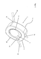
- FIG. 3 shows an inlet section 31 for a device 1 according to the invention.
- the inlet section 31 is formed on the inlet surface 5 of the housing 2.
- a connection section 32 is provided on a side of the inlet section 31 facing away from the inlet surface 5.
- the connection section 32 serves to connect the inlet section 31 to a fluid supply, that is, for example, to a hose as supply line 33.
- the inlet section serves in particular for the supply of a biological fluid, such as blood.
- an opening 36 is provided which the inlet of the liquid in the first chamber 3 - not shown in FIG FIG. 3 - forms.
- the inlet portion is formed and arranged at an acute angle relative to the inlet surface 5.
- this inlet angle is about 15 °.
- the inlet angle may be varied, with the inlet angle preferably being less than 45 °, more preferably less than 25 °, and especially between 15 ° -20 °.
- a tangential flow with the biological fluid is made possible.
- a tangential supply and discharge guidance can be made possible in this way. This, in turn, may allow installation in a compact format, for example in a portable device.
- FIG. 4 shows a lid 50 of the device according to the invention.
- the lid 50 is in particular designed such that it is below the in FIG. 3 can be arranged so that the introduced through the inlet portion 31 liquid is directed to the lid 50.
- the cover 50 has a channel-like portion 51. "Channel-like” is understood to mean that the channel-like portion 51 is a depression in the lid 50, which defines a direction of flow of the liquid conducted on the lid 50.
- the arrow in FIG. 4 indicates a flow direction of the introduced liquid along the lid 50.
- the channel-like portion 51 has a first end 52 and a second end 53.
- the channel-like portion 51 is formed to expand in the flow direction from the first end 52 to the second end 53 thereof. This leads to a distribution of the introduced liquid over a larger area and thus allows a more homogeneous flow of the lid 50 downstream components, ie substantially the first chamber 3 with the gas exchange means.
- the cover 50 or the channel-like portion 51 of the lid 50 is preferably formed such that the channel-like portion 51 widens at an angle of between 10 ° -20 °.
- the embodiment shown is the Aufspannwinkel, ie the angle by which the channel-like portion 51 after this definition widens, 14 °.
- the angle that the individual legs of the channel-like section 51 include is twice the clamping angle, ie 28 ° in the embodiment shown.
- the inlet section 31 and the cover 50 are formed as individual components, it is conceivable that the inlet section 31 is also formed integrally with the cover 50.
- the lid 50 could, for example, be arranged in the opening 36 of the inlet surface 5 so that the liquid introduced through the inlet section 31 is introduced directly into the chamber 3.
- the lid may also have an inclined plane which, for example, following the inclination of the inlet section, leads from the inlet surface 5 through the opening 36 into the first chamber.
- the cover due to the widening channel and at the same time a diaphragm seal component since the inflowing liquid is distributed over a larger area and thus the flow pressure is reduced.
- the lid according to the execution after FIG. 4 also a distribution means for the inflowing liquid.
- the cover 50 may also be formed separately from a pressure transmitter or from a distributor means, for example only as a cover of the inlet surface 5 on the outside of the inlet surface 5 or on the inside of the inlet surface 5.
- a separate diaphragm seal and / or or a separate distribution means may be provided in the device.
- the device according to the invention only a decarboxylation without simultaneous oxygenation should be carried out with the device according to the invention. Since it is a fundamental endeavor to keep extracorporeal volume flows as low as possible, for example when withdrawing and returning blood into a body, the volume flows for such CO 2 removal systems are typically in the range below 21 / min, preferably at approximately 0 , 3-1 l / min. In order to ensure a sufficient flow and an effective gas exchange at such low flow rates, the dimensioning of the fiber bundle or the cavity is crucial.
- the cavity of the gas exchanger so the first chamber, a diameter of 70mm and a stack thickness of the gas exchange agent, here the fiber bundle, selected from 25mm.
- a gas exchange surface of about 0.6m 2 .
Landscapes
- Health & Medical Sciences (AREA)
- Emergency Medicine (AREA)
- Urology & Nephrology (AREA)
- Heart & Thoracic Surgery (AREA)
- Vascular Medicine (AREA)
- Engineering & Computer Science (AREA)
- Anesthesiology (AREA)
- Biomedical Technology (AREA)
- Hematology (AREA)
- Life Sciences & Earth Sciences (AREA)
- Animal Behavior & Ethology (AREA)
- General Health & Medical Sciences (AREA)
- Public Health (AREA)
- Veterinary Medicine (AREA)
- Chemical & Material Sciences (AREA)
- Chemical Kinetics & Catalysis (AREA)
- External Artificial Organs (AREA)
- Separation Using Semi-Permeable Membranes (AREA)
Abstract
Eine Vorrichtung (1) zur Behandlung einer biologischen Flüssigkeit, umfasst ein Gehäuse (2) mit einer ersten, eine Kavität bildenden Kammer (3), die zur Aufnahme der zu behandelnden Flüssigkeit ausgebildet ist, sowie wenigstens ein Gasaustauschmittel (7, 13, 19, 21), das zumindest teilweise in der ersten Kammer (3) angeordnet ist. In einer Oberfläche (5) des Gehäuses (2) ist ein Einlassabschnitt (31) zum Einlass der zu behandelnden Flüssigkeit in die erste Kammer (3) ausgebildet. Der Einlassabschnitt (31) ist in einem spitzen Winkel relativ zu der Oberfläche (5) des Gehäuses (2) ausgebildet. Eine derartige Vorrichtung erlaubt einen Gasaustausch, beispielsweise in einem Lungenersatzverfahren.

Description
Die Erfindung betrifft eine Vorrichtung zur Behandlung einer biologischen Flüssigkeit gemäß dem Oberbegriff des unabhängigen Anspruchs und insbesondere eine Vorrichtung mit einer Kammer, die zur Aufnahme der biologischen Flüssigkeit bestimmt ist, und einem Gasaustauschmittel.The invention relates to a device for the treatment of a biological fluid according to the preamble of the independent claim and in particular to a device having a chamber which is intended to receive the biological fluid, and a gas exchange medium.
Dabei kann es sich um eine Begasungs- bzw. Entgasungsvorrichtung handeln, bei der ein oder mehrere Gase von einem Medium in ein anderes Medium übertreten können, oder eine Gasaustauschvorrichtung, die den Austausch eines oder mehrerer Gase zwischen zwei Medien ermöglicht. Solche Vorrichtungen finden Anwendung in der Chemie, der Biotechnologie und der Medizin. Ein wichtiger Einsatzzweck in der Medizin ist die Anreicherung einer biologischen Flüssigkeit, insbesondere von Blut, mit Sauerstoff und/oder die Entfernung von Kohlenstoffdioxid aus der Flüssigkeit, speziell Blut. Solche Maßnahmen sind bspw. bei der Behandlung von verschiedenen Lungenerkrankungen notwendig. Solche Maßnahmen können weiterhin z.B. auch bei akutem Lungenversagen, sowie zum Ersatz der Lunge während deren Umgehung mit einem extrakorporalen Kreislauf, mit unterschiedlichem Ausmaß bei der mechanischen Herzunterstützung und zur Ermöglichung am stillgestellten Herzen zu operieren, notwendig sein.It may be a gassing or degassing, in which one or more gases can pass from one medium to another medium, or a gas exchange device, which allows the exchange of one or more gases between two media. Such devices find application in chemistry, biotechnology and medicine. An important use in medicine is the enrichment of a biological fluid, especially blood, with oxygen and / or the removal of carbon dioxide from the fluid, especially blood. Such measures are, for example, in the treatment of various lung diseases necessary. Such measures may continue to be used e.g. also be necessary in acute lung injury, as well as to replace the lungs during their circumvention with an extracorporeal circulation, to varying degrees in the mechanical heart support and to enable the immobilized heart.
Zudem stellt die derzeit einzige langfristig effektive Therapieoption für Patienten mit endgradiger funktioneller Lungenerkrankung die Lungentransplantation dar. Eine andere medizinische Lösung, um dauerhaft die Funktion der Lunge zu ersetzen, existiert hingegen nicht. Bei Patienten, die unter chronischen Lungenerkrankungen leiden und nicht oder nicht unmittelbar für eine Lungentransplantation in Betracht kommen, besteht daher ein Bedürfnis nach künstlichen Lungenersatzverfahren.In addition, currently the only long-term effective treatment option for patients with end-stage functional lung disease is lung transplantation. However, another medical solution to permanently replace lung function does not exist. In patients suffering from chronic lung disease Therefore, there is a need for artificial lung replacement procedures which are not or not immediately eligible for lung transplantation.
Um ein derartiges Lungenersatzverfahren zu ermöglichen, sind so genannte Blutgastauscher aus dem Stand der Technik bekannt.To enable such a lung replacement procedure, so-called blood gas exchangers are known from the prior art.
Ein Blutgastauscher, häufig auch als Oxygenator oder künstliche Lunge bezeichnet, wird entweder zur vollständigen, kurzzeitigen Übernahme der Lungenfunktion während einer Operation am offenen Herzen oder als vollständige oder teilweise, langfristige Unterstützung der Lunge auf der Intensivstation eingesetzt. Die Hauptfunktion eines solchen Blutgastauschers besteht in der Abgabe von Sauerstoff an das Blut (Oxygenierung) und in der Aufnahme von Kohlenstoffdioxid aus dem Blut (Decarboxylierung). Der Gasaustausch findet beispielsweise mittels Hohlfasermembranen statt, die in einem extrakorporalen Gasaustauscher von Blut umflossen werden, während gleichzeitig durch das Innere der Faser sauerstoffreiches bzw. kohlenstoffdioxidarmes Gas geleitet wird. Durch den Konzentrationsunterschied können Sauerstoff bzw. Kohlenstoffdioxid in jeweils entgegengesetzter Richtung durch eine semi-permeable Membran - typischerweise eine gaspermeable Membran - diffundieren. Die Fasern lassen sich kommerziell beziehen und werden beispielsweise in viereckigen Fasermatten oder als Einzelfaser auf Spulen gewickelt ausgeliefert.A blood gas exchanger, often referred to as an oxygenator or artificial lung, is used either for complete, transient pulmonary function during open heart surgery or as full or partial, long-term lung support for the intensive care unit. The main function of such a blood gas exchanger is the delivery of oxygen to the blood (oxygenation) and the uptake of carbon dioxide from the blood (decarboxylation). The gas exchange takes place, for example, by means of hollow-fiber membranes, which are circumscribed in an extracorporeal gas exchanger of blood, while simultaneously passing oxygen-rich or low-carbon gas through the interior of the fiber. Owing to the difference in concentration, oxygen or carbon dioxide can diffuse in opposite directions through a semi-permeable membrane, typically a gas-permeable membrane. The fibers can be obtained commercially and are delivered, for example, in square fiber mats or as a single fiber wound on reels.
Es gibt zwei verschiedene Herstellungsverfahren, um Blutgastauscher aus den Fasermatten herzustellen, nämlich gewickelt und gelegt. Beispielhaft soll hier nur eine Fasermattenherstellung anhand der gelegten Variante skizziert werden, um die Hintergründe der Erfindung besser zu verdeutlichen.There are two different manufacturing processes for making blood gas exchangers from the fiber mats, namely wound and laid. By way of example, only a fiber mat production will be outlined here with reference to the variant set in order to clarify the background of the invention better.
Bei der gelegten Variante werden die individuellen Fasermatten kreuzweise geschichtet, wodurch sich ein quaderförmiges, insbesondere ein kubisches, paketförmiges Faserbündel ergibt. Das Faserbündel wird durch zwei Deckel, welche die Anströmgeometrie enthalten, und durch eine Vergussmasse nach außen hin abgegrenzt. Die Deckel werden unterhalb und oberhalb des Faserbündels platziert. Die vier Seiten des Faserbündels werden auf einer Zentrifuge Seite für Seite nacheinander vergossen und so mit den Deckeln verbunden. Kommerziell erhältliche Gasaustauscher, die auf diese Weise hergestellt werden, besitzen weiterhin eine entsprechende kubische Kavität, in welche die Fasern eingebettet sind und vom Blut umströmt werden. Im Allgemeinen werden diese Gasaustauscher an einer der vier Ecken des Faserbündels bzw. der Kavität angeströmt. Die Anschlüsse für die blutführenden Schläuche sind dabei orthogonal zu den Deckeln der Gasaustauscher orientiert.In the laid variant, the individual fiber mats are layered crosswise, resulting in a cuboid, in particular a cubic, packet-shaped fiber bundle. The fiber bundle is delimited by two covers, which contain the Anströmgeometrie, and by a potting compound to the outside. The lids are placed below and above the fiber bundle. The Four sides of the fiber bundle are successively potted on a centrifuge side by side and thus connected to the lids. Commercially available gas exchangers produced in this manner also have a corresponding cubic cavity in which the fibers are embedded and circulated around the blood. In general, these gas exchangers are supplied at one of the four corners of the fiber bundle or the cavity. The connections for the blood-carrying hoses are oriented orthogonally to the covers of the gas exchanger.
Auf Grund ihrer Größe und der Anordnung der Anschlüsse für die blutführenden Schläuche beschränkt sich der Einsatz dieser Gasaustauscher jedoch auf stationäre Anwendungen, bei denen der Patient - wach oder sediert - im Bett liegt. Da Patienten mit chronischen Lungenerkrankungen, die auf einen dieser bekannten Gasaustauscher angewiesen sind, somit stark in ihrer Mobilität eingeschränkt sind, ist nicht nur die Lebensqualität der Patienten erheblich vermindert. Auch moderne Therapieansätze, die eine Mobilisierung der Patienten anstreben, sind nicht durchführbar.However, due to their size and the arrangement of the connections for the blood-carrying hoses, the use of these gas exchangers is limited to stationary applications in which the patient - awake or sedated - lies in bed. Since patients with chronic lung diseases, which rely on one of these known gas exchangers, are thus severely limited in their mobility, not only the quality of life of the patients is considerably reduced. Even modern therapeutic approaches that seek to mobilize patients are not feasible.
Bekannte Gasaustauscher, insbesondere Gasaustauscher, die für den Einsatz an einer Herzlungenmaschine (HLM) vorgesehen sind, sind zu voluminös und zu schwer, um beispielsweise von einem Patienten am Körper getragen werden zu können. Gegen einen derartigen mobilen Einsatz einer tragbaren Gasaustauschvorrichtung spräche dabei auch die bislang übliche orthogonale Orientierung der Schläuche und Konnektoren bei derartigen Gasaustauschern, was einen großen Raumbedarf des Gasaustauschers bedingt.Known gas exchangers, in particular gas exchangers, which are intended for use on a heart lung machine (HLM) are too bulky and too heavy to be worn by a patient on the body, for example. Against such a mobile use of a portable gas exchange device would also speak the hitherto conventional orthogonal orientation of the hoses and connectors in such gas exchangers, which requires a large space requirement of the gas exchanger.
Der vorliegenden Erfindung liegt die Aufgabe zugrunde, eine verbesserte Vorrichtung zur Behandlung einer biologischen Flüssigkeit bereitzustellen, welche wenigstens einen der Nachteile der bekannten Systeme löst und die einen platzsparenderen Gasaustauscher, insbesondere auch für eine mobile Anwendung des Gasaustauschers bereitstellt. Vornehmlich ist es eine Aufgabe der vorliegenden Erfindung, einen für einen Patienten tragbaren Gasaustauscher bereitzustellen. Es ist insbesondere eine Aufgabe der vorliegenden Erfindung, einen Platzbedarf eines Gasaustauschers zu reduzieren, so dass es ermöglicht ist, den Gasaustauscher, vorzugsweise direkt, an einem Patientenkörper zu transportieren.The present invention has for its object to provide an improved apparatus for the treatment of a biological fluid, which solves at least one of the disadvantages of the known systems and the space-saving gas exchanger, in particular for a mobile application of the gas exchanger provides. Notably, it is an object of the present invention to provide a portable gas exchanger for a patient. It is in particular an object of the present invention to reduce the space requirement of a gas exchanger so that it is possible to transport the gas exchanger, preferably directly, to a patient's body.
Die Aufgabe der vorliegenden Erfindung wird durch eine Vorrichtung gemäß Anspruch 1 gelöst. Vorteilhafte Weiterbildungen der Erfindung sind Gegenstand der abhängigen Ansprüche.The object of the present invention is achieved by a device according to
Gemäß einem Aspekt der Erfindung wird eine Vorrichtung zur Behandlung einer biologischen Flüssigkeit bereitgestellt, die ein Gehäuse mit zumindest einer ersten, eine Kavität bildenden Kammer, sowie ein zumindest teilweise in der ersten Kammer angeordnetes Gasaustauschmittel aufweist. Die erste Kammer ist zur Aufnahme einer zu behandelnden Flüssigkeit, hier insbesondere einer biologischen Flüssigkeit, wie beispielsweise Blut, bestimmt. An einer Oberfläche des Gehäuses, die im Folgenden auch als Einlassoberfläche bezeichnet wird, ist ein Einlassabschnitt zum Einlass der zu behandelnden Flüssigkeit in die erste Kammer ausgebildet. Der Einlassabschnitt ist dabei erfindungsgemäß in einem spitzen Winkel relativ zu der Einlassoberfläche des Gehäuses ausgebildet, an der der Einlassabschnitt ausgebildet ist.According to one aspect of the invention, there is provided a biological fluid treatment apparatus comprising a housing having at least a first cavity forming chamber and a gas exchange means at least partially disposed in the first chamber. The first chamber is intended for receiving a liquid to be treated, in particular a biological fluid, such as blood. On one surface of the housing, which is also referred to below as the inlet surface, an inlet section for the inlet of the liquid to be treated is formed in the first chamber. According to the invention, the inlet section is formed at an acute angle relative to the inlet surface of the housing on which the inlet section is formed.
Insbesondere kann die erfindungsgemäße Vorrichtung als Gasaustauschmittel eine zweite, zumindest teilweise in der ersten Kammer ausgebildete Kammer aufweisen oder eine zweite Kammer bilden. Die zweite Kammer ist zur Aufnahme eines ersten Fluids, insbesondere eines ersten Gases bestimmt. Die zweite Kammer kann durch mindestens eine semi-permeable Membran von der ersten Kammer getrennt ausgebildet sein. Vorzugsweise ist die semi-permeable Membran eine gasdurchlässige und flüssigkeitsundurchlässige Membran. Die Membran kann beispielsweise einem Transfer von zumindest einer vorbestimmbaren Molekülart zwischen erster und zweiter Kammer dienen. Der Transfer kann dabei von der ersten Kammer zu der zweiten Kammer und/oder von der zweiten Kammer zu der ersten Kammer erfolgen. Es kann dabei auch eine Mehrzahl erster und/oder zweiter Kammern vorgesehen sein.In particular, the device according to the invention may comprise as a gas exchange means a second, at least partially formed in the first chamber chamber or form a second chamber. The second chamber is intended to receive a first fluid, in particular a first gas. The second chamber may be formed by at least one semi-permeable membrane separated from the first chamber. Preferably, the semi-permeable membrane is a gas permeable and liquid impermeable membrane. The membrane can serve, for example, a transfer of at least one predeterminable type of molecule between the first and second chambers. The transfer can take place from the first chamber to the second chamber and / or from the second chamber to the first chamber. It can also be provided a plurality of first and / or second chambers.
"Semi-permeabel" soll im Zusammenhang der Erfindung derart verstanden werden, dass die Wandung teilweise durchlässig ist. Eine Durchlässigkeit soll dabei für vorbestimmte Moleküle gegeben sein, insbesondere für spezielle Gasmoleküle wie beispielsweise Sauerstoff oder Kohlenstoffdioxid. Insofern beinhaltet der Begriff "semi-permeabel" auch eine selektive Permeabilität für spezifische, vorbestimmbare Moleküle oder Verbindungen."Semi-permeable" is to be understood in the context of the invention such that the wall is partially permeable. A permeability should be given for predetermined molecules, in particular for special gas molecules such as oxygen or carbon dioxide. In this respect, the term "semi-permeable" also includes a selective permeability for specific, predeterminable molecules or compounds.
Das Gasaustauschmittel, insbesondere die zweite Kammer, kann derart ausgebildet und angeordnet sein, dass das Gasaustauschmittel von der mindestens einen gasdurchlässigen und flüssigkeitsundurchlässigen Membran abgegrenzt bzw. umschlossen ist und derart, dass eine biologische Flüssigkeit, die in der ersten Kammer vorgesehen ist, das Gasaustauschmittel zumindest teilweise umgeben oder umströmen kann.The gas exchange means, in particular the second chamber, may be arranged and arranged such that the gas exchange means is defined by the at least one gas permeable and liquid impermeable membrane and such that a biological fluid provided in the first chamber at least the gas exchange means partially surrounded or can flow around.
Soweit im Folgenden auf eine "zweite Kammer" Bezug genommen wird, dient dies lediglich zur erleichterten Verständlichkeit der vorliegenden Erfindung. Die zweite Kammer ist jedoch lediglich als Teil bestimmter speziellerer Ausführungsformen des Gasaustauschmittels zu verstehen. Das Gasaustauschmittel bezeichnet dabei alle diejenigen Strukturen, die im Sinne der Erfindung einen Gasaustausch zwischen einer zu behandelnden Flüssigkeit, wie beispielsweise einer biologischen Flüssigkeit wie Blut, und einem für den Gasaustausch notwendigen Fluid ermöglichen.Insofar as reference is made below to a "second chamber", this is merely to facilitate understanding of the present invention. However, the second chamber is to be understood as merely part of certain more specific embodiments of the gas exchange means. The gas exchange agent refers to all those structures that allow for the purposes of the invention, a gas exchange between a liquid to be treated, such as a biological fluid such as blood, and a necessary for gas exchange fluid.
Die Membran zwischen der ersten Kammer und dem Gasaustauschmittel ist typischerweise halbdurchlässig oder semi-permeabel und besitzt normalerweise Poren, deren Größe die Funktion und den Effekt der jeweiligen Membran bestimmen. Mit anderen Worten kann jede Membran einerseits eine poröse Membran sein, d.h. eine Membran, die diskrete Poren aufweist. Andererseits kann die Membran eine homogene Löslichkeitsmembran ohne diskrete Poren sein, in der der Stofftransport durch Lösung des Permeats (z.B. des Gases) im Polymer erfolgt und die Trennung aufgrund unterschiedlicher Löslichkeiten im Polymer stattfindet. Vorzugsweise ist die Membran eine nicht-poröse permeable Membran. So kann ein Gasaustausch zwischen dem Fluid in dem Gasaustauschmittel und der biologischen Flüssigkeit in der ersten Kammer ermöglicht werden. Der Gasaustausch kann dem konvektiven und diffusiven Stoffaustausch unterliegen. Vorzugsweise ist der Gasaustausch diffusiv und wird über die Differenz der Gaskonzentration auf beiden Seiten der Membran bestimmt.The membrane between the first chamber and the gas exchange medium is typically semi-permeable or semi-permeable and normally has pores whose size dictates the function and effect of the particular membrane. In other words, each membrane may on the one hand be a porous membrane, ie a membrane which has discrete pores. On the other hand, the membrane can be a homogeneous solubility membrane without discrete pores, in which the mass transport through Solution of the permeate (eg of the gas) takes place in the polymer and the separation takes place due to different solubilities in the polymer. Preferably, the membrane is a non-porous permeable membrane. Thus, gas exchange between the fluid in the gas exchange means and the biological fluid in the first chamber may be allowed. Gas exchange may be subject to convective and diffusive mass transfer. Preferably, the gas exchange is diffusive and is determined by the difference in gas concentration on both sides of the membrane.
Die erfindungsgemäße Vorrichtung zur Behandlung einer biologischen Flüssigkeit kann durch die gewinkelte Anordnung des Einlassabschnitts relativ zu der Oberfläche des Gehäuses eine platzsparendere Einleitung der Flüssigkeit in die erste Kammer ermöglichen im Vergleich zu den üblicherweise in den bekannten stationären Systemen verwendeten orthogonalen Anschlüssen. Es kann erfindungsgemäß eine tangentiale Anströmung und Zu- und Ableitung der Flüssigkeit erfolgen, so dass Zu- und Ableitungen in nahezu derselben Ebene geführt werden können, in der auch das Gehäuse bzw. die Gehäuseoberfläche ausgebildet ist. Dies kann insbesondere einen Transport nahe oder auch direkt am Körper, beispielsweise eines Patienten, ermöglichen. Dies kann eine Mobilität der Vorrichtung und folglich auch eines Verwenders erhöhen.The biologic fluid handling apparatus of the present invention, through the angled arrangement of the inlet section relative to the surface of the housing, may allow for a more space-efficient introduction of the fluid into the first chamber as compared to the orthogonal ports commonly used in the known stationary systems. According to the invention, a tangential flow and supply and discharge of the liquid can take place, so that supply and discharge lines can be guided in almost the same plane in which the housing or the housing surface is also formed. This can in particular enable a transport close or directly on the body, for example of a patient. This can increase a mobility of the device and consequently of a user.
Es versteht sich dabei, dass alle mit der Flüssigkeit in Kontakt kommenden Komponenten entweder steril herstellbar oder sterilisierbar sind.It goes without saying that all components coming into contact with the liquid are either sterile or sterilizable.
Vorzugsweise ist die erste Kammer als Durchflusskammer gestaltet und weist einen Einlass und einen von dem Einlass separaten Auslass auf. Vorzugsweise kann die zweite Kammer ebenso als Durchflusskammer ausgebildet sein. Die erste Kammer kann dabei bevorzugt zum Durchfluss in einer Richtung gegen oder quer zur Durchflussrichtung der zweiten Kammer bestimmt sein.Preferably, the first chamber is configured as a flow chamber and has an inlet and an outlet separate from the inlet. Preferably, the second chamber may also be formed as a flow chamber. The first chamber may preferably be intended to flow in one direction against or transverse to the direction of flow of the second chamber.
In einigen Ausführungsformen der Erfindung ist das Gasaustauschmittel, insbesondere die zweite Kammer, in mehrere Unterkammern unterteilt, sodass die Vorrichtung mehrere zweite Kammern umfasst, die zur Aufnahme eines Gases bestimmt und von der ersten Kammer durch eine gasdurchlässige und flüssigkeitsundurchlässige Membran getrennt sind. Die mehreren zweiten Kammern befinden sich innerhalb der ersten Kammer bzw. sind von der ersten Kammer im Wesentlichen umgeben. Vorzugsweise haben die zweiten Kammern einen länglichen und bevorzugt im Wesentlichen zylinderförmigen Aufbau, der im Querschnitt einen oder mehrere durchgängige Hohlräume aufweist. Eine den Querschnitt abgrenzende Wand der zweiten Kammern bildet zumindest teilweise die gasdurchlässige und flüssigkeitsundurchlässige Membran.In some embodiments of the invention, the gas exchange means, in particular the second chamber, is subdivided into a plurality of subchambers, so that the device comprises a plurality of second chambers intended to receive a gas and separated from the first chamber by a gas-permeable and liquid-impermeable membrane. The plurality of second chambers are within the first chamber or are substantially surrounded by the first chamber. Preferably, the second chambers have an elongated and preferably substantially cylindrical structure, which has one or more continuous cavities in cross-section. A wall of the second chambers delimiting the cross-section at least partially forms the gas-permeable and liquid-impermeable membrane.
In einer Weiterbildung der Erfindung sind die mehreren zweiten Kammern in einer oder mehreren Reihen nebeneinander und bevorzugt auch in einem Abstand voneinander angeordnet. Ferner können die mehreren zweiten Kammern in mehreren Lagen angeordnet sein. Die zweiten Kammern sind beispielsweise als Hohlkörper, bevorzugt als Hohlfasern, ausgebildet, sodass die Wand jedes Hohlkörpers bzw. jeder Hohlfaser die gasdurchlässige und flüssigkeitsundurchlässige Membran bildet. Der Abstand zwischen den mehreren, nebeneinander angeordneten zweiten Kammern liegt bevorzugt im Bereich von 50 µm bis 1 cm, weiter bevorzugt im Bereich von 100 µm bis 1 mm, und noch weiter bevorzugt im Bereich von 100 µm bis 500 µm. Dieser Abstand kann beliebig gewählt bzw. eingestellt werden.In a development of the invention, the plurality of second chambers are arranged in one or more rows next to one another and preferably also at a distance from one another. Furthermore, the plurality of second chambers may be arranged in multiple layers. The second chambers are formed, for example, as a hollow body, preferably as hollow fibers, so that the wall of each hollow body or each hollow fiber forms the gas-permeable and liquid-impermeable membrane. The distance between the plurality of juxtaposed second chambers is preferably in the range of 50 μm to 1 cm, more preferably in the range of 100 μm to 1 mm, and still more preferably in the range of 100 μm to 500 μm. This distance can be chosen or set as desired.
In vorteilhaften Weiterbildungen der vorliegenden Erfindung weist das Gehäuse des Weiteren einen Auslassabschnitt an einer Oberfläche, der Auslassoberfläche, des Gehäuses zum Auslassen der biologischen Flüssigkeit aus der Vorrichtung auf. Dabei kann der Auslassabschnitt ebenfalls in einem spitzen Winkel relativ zu der Oberfläche des Gehäuses angeordnet sein. Der Winkel, den der Auslassabschnitt gegen die Auslassoberfläche einnimmt, kann dabei insbesondere derselbe Winkel sein, wie derjenige, den der Einlassabschnitt gegen die entsprechende Einlassoberfläche einnimmt. Auf diese Weise kann ein Platzbedarf der Vorrichtung weiter reduziert werden, da eine bislang notwendige platzeinnehmende orthogonale Anordnung des Auslassanschlusses und somit eine entsprechende orthogonale Führung von Leitungen vermieden werden kann.In advantageous developments of the present invention, the housing further has an outlet section on a surface, the outlet surface, of the housing for discharging the biological fluid from the device. In this case, the outlet section can also be arranged at an acute angle relative to the surface of the housing. The angle which the outlet section assumes against the outlet surface may in particular be the same angle as that which the inlet section assumes against the corresponding inlet surface. In this way, a space requirement of the device can be further reduced, since a previously required space-taking orthogonal arrangement the outlet port and thus a corresponding orthogonal guidance of lines can be avoided.
Es ist alternativ denkbar, dass der Winkel des Auslassabschnitts sich von dem Winkel des Einlassabschnitts gegen die entsprechende Oberfläche unterscheidet. Dies kann, gerade im Hinblick auf eine Mobilität eines Trägers, eine Berücksichtigung an die Anatomie des Trägers oder an die Position der Vorrichtung an einem Träger oder in einem Gehäuse oder einer Tragevorrichtung ermöglichen. Der Auslassabschnitt kann grundsätzlich auch an derselben Oberfläche des Gehäuses vorgesehen sein, wie der Einlassabschnitt.It is alternatively conceivable that the angle of the outlet section is different from the angle of the inlet section to the corresponding surface. This may allow for consideration of the anatomy of the wearer or the position of the device on a wearer or in a housing or carrying device, particularly with regard to mobility of a wearer. The outlet section may in principle also be provided on the same surface of the housing as the inlet section.
Es versteht sich auch, dass die relative Position von Einlassabschnitt und Auslassabschnitt variieren kann. So können der Einlass- und der Auslassabschnitt beispielsweise waagerecht nebeneinander, oder senkrecht übereinander angeordnet sein. Auch ist sowohl eine parallele oder eine orthogonal Anordnung des Auslassabschnitts relativ zu dem Einlassabschnitt möglich. In einigen Ausführungsformen der vorliegenden Erfindung ist der Auslassabschnitt dem Einlassabschnitt diametral gegenüberliegend. Es ist auch denkbar, dass der Einlassabschnitt an einer Position angeordnet ist, die sich, in einer Position, in der die erfindungsgemäße Vorrichtung üblicherweise verwendet wird, an einem oberen Abschnitt der Gasaustauschvorrichtung befindet. Der Auslassabschnitt kann in diesem Fall insbesondere an einem unteren Abschnitt der Vorrichtung ausgebildet sein. Dadurch kann ein Durchfluss durch die Vorrichtung von dem Einlassabschnitt zu dem Auslassabschnitt erleichtert werden, insbesondere deshalb, da die Gravitationskraft den Fluss der Flüssigkeit durch die Vorrichtung unterstützen kann. Auf diese Weise kann ein Herz-KreislaufSystem eines Patienten, der die Gasaustauschvorrichtung trägt, entlastet werden.It will also be understood that the relative position of inlet section and outlet section may vary. For example, the inlet and outlet sections can be arranged horizontally next to one another, or vertically above one another. Also, both a parallel or an orthogonal arrangement of the outlet section relative to the inlet section is possible. In some embodiments of the present invention, the outlet portion is diametrically opposed to the inlet portion. It is also conceivable that the inlet section is arranged at a position which, at a position in which the device according to the invention is commonly used, is located at an upper section of the gas exchange device. The outlet section may in this case be formed in particular on a lower section of the device. Thereby, a flow through the device from the inlet section to the outlet section can be facilitated, in particular because the gravitational force can assist the flow of the liquid through the device. In this way, a cardiovascular system of a patient wearing the gas exchange device can be relieved.
In einigen Weiterbildungen der Erfindung ist der Winkel, den der Einlassabschnitt relativ zu der jeweiligen Einlassoberfläche, also der Einlasswinkel, und/oder der Winkel, den der Auslassabschnitt relativ zu der Auslassoberfläche des Gehäuses, also der Auslasswinkel, einnehmen, kleiner als 45°, vorzugsweise kleiner als 25°, insbesondere zwischen 15° - 20°.In some embodiments of the invention, the angle that the inlet portion is relative to the respective inlet surface, that is, the inlet angle, and / or the angle that the outlet portion relative to the outlet surface of the housing, ie the outlet angle, assume less than 45 °, preferably less than 25 °, in particular between 15 ° - 20 °.
Der Einlassabschnitt kann derart an der Oberfläche des Gehäuses ausgebildet sein, dass eine durch den Einlassabschnitt geleitete biologische Flüssigkeit so in die erste Kammer einleitbar ist, dass diese an einem zentralen Bereich des Gasaustauschmittels, insbesondere des Faserbündels, in die erste Kammer eingeleitet wird. Ein zentraler Bereich bezeichnet dabei einen Bereich des Gasaustauschmittels, bzw. des Faserbündels, der sich in einer lateralen Ausdehnung, also in denjenigen Richtungen, die im Wesentlichen eine zu der Einlassoberfläche parallele Oberfläche aufspannen, im Zentrum bzw. im Bereich des Zentrums des Faserbündels befindet.The inlet section may be formed on the surface of the housing such that a biological fluid conducted through the inlet section may be introduced into the first chamber such that it is introduced into the first chamber at a central region of the gas exchange means, in particular the fiber bundle. In this case, a central region designates a region of the gas exchange agent or of the fiber bundle that is located in the center or in the region of the center of the fiber bundle in a lateral extent, that is to say in those directions which essentially span a surface parallel to the inlet surface.
Es versteht sich, dass auch die Zu- und/oder Ableitung für das erste Fluid oder weitere Komponenten in das Gehäuse tangential bzw. in einem flachen Winkel, beispielsweise relativ zu einer Umfangsfläche des Gehäuses, erfolgen kann. Auf diese Weise kann eine weitere Platzersparnis für die Gasaustauschvorrichtung ermöglicht werden.It is understood that the supply and / or discharge for the first fluid or other components in the housing tangentially or at a shallow angle, for example, relative to a peripheral surface of the housing can take place. In this way, a further space saving for the gas exchange device can be made possible.
In einigen Ausführungsformen ist das Gasaustauschmittel, insbesondere die zweite Kammer bzw. die zweiten Kammern, als ein durch eine Mehrzahl von Hohlfasern gebildetes Faserbündel ausgebildet, das zumindest teilweise in der ersten Kammer angeordnet ist.In some embodiments, the gas exchange means, in particular the second chamber (s), is formed as a fiber bundle formed by a plurality of hollow fibers at least partially disposed in the first chamber.
Die erste Kammer kann eine, im Wesentlichen, zylindrische Form aufweisen. Auf diese Weise wird eine Kavität gebildet, die im Wesentlichen eine Zylinderform aufweist. Das bedeutet, die Kavität weist in den Randbereichen keine Ecken oder unstete Randbereiche auf. Zusätzlich oder alternativ kann auch das Gasaustauschmittel, insbesondere das Faserbündel, eine, im Wesentlichen, zylindrische Form aufweisen. In einigen Ausführungsformen kann die Form des Gasaustauschmittels bzw. des Faserbündels und die Form der Kavität, also die Innenkontur der ersten Kammer, aufeinander abgestimmte Formen und Dimensionen aufweisen, so dass das Gasaustauschmittel möglichst ideal in der Kavität der ersten Kammer angeordnet sein kann. Eine ideale Anordnung in diesem Zusammenhang wäre eine Anordnung, in der ein größtmöglicher Bereich des Gasaustauschmittels gleichmäßig von der biologischen Flüssigkeit, vorzugsweise laminar und mit im Wesentlichen konstanter, gleichmäßiger Fließgeschwindigkeit über den gesamten Strömungsquerschnitt, umströmt wird.The first chamber may have a substantially cylindrical shape. In this way, a cavity is formed, which has a substantially cylindrical shape. This means that the cavity has no corners or unsteady edge areas in the edge areas. Additionally or alternatively, the gas exchange medium, in particular the fiber bundle, may also have an essentially cylindrical shape. In some embodiments, the shape of the gas exchange means or the fiber bundle and the shape of the cavity, that is, the inner contour of the first chamber, have matched shapes and dimensions, so that the gas exchange agent ideally located in the cavity of the first chamber can be arranged. An ideal arrangement in this connection would be an arrangement in which the largest possible area of the gas exchange medium flows uniformly around the biological fluid, preferably in a laminar manner and at a substantially constant, uniform flow rate over the entire flow cross section.
Aus dem Stand der Technik sind dem Fachmann Vorrichtungen bekannt, die einen Gasaustauscher mit einer kubischen Kavität zum Durchfluss einer biologischen Flüssigkeit aufweisen. Durch das Anordnen des Auslassabschnitts und des Einlassabschnitts in einem spitzen Winkel zu der entsprechenden Oberfläche kann eine parallele oder zumindest annähernd parallele Anströmung der zweiten Kammern erfolgen. Die Verwendung einer zylindrischen Kavität entsprechend der oben dargestellten Weiterbildung der Erfindung gemäß einiger Ausführungsformen kann eine homogenere Verteilung der Strömungsgeschwindigkeit im Vergleich zu einer kubischen Kavität ermöglichen.From the prior art devices are known in the art, which have a gas exchanger with a cubic cavity for the passage of a biological fluid. By arranging the outlet section and the inlet section at an acute angle to the corresponding surface, a parallel or at least approximately parallel flow of the second chambers can take place. The use of a cylindrical cavity according to the embodiment of the invention set forth above, according to some embodiments, may allow a more homogeneous distribution of the flow velocity as compared to a cubic cavity.
Die Verwendung eines zylindrischen Faserbündels kann zudem eine bessere Ausnutzung der Kavität, also des zum Gasaustausch zur Verfügung stehenden Raumes in der ersten Kammer ermöglichen. Dies kann die Zuverlässigkeit und Haltbarkeit der Vorrichtung, beispielsweise durch Reduzierung auftretender Verwirbelungen und sich daraus ergebende Degenerationen, verringern. Solche Degenerationen finden insbesondere in Eckbereichen einer kubischen Kavität statt, woraus bei Verwendung von Blut als Flüssigkeit in der ersten Kammer ein erhöhtes Koagulationsrisiko resultiert. Die Ausbildung einer zylindrischen Kavität, unter Vermeidung derartiger Eckbereiche kann dieses Risiko reduzieren. Zylindrische Faserbündel sind natürlich auch grundsätzlich zur Anströmung mittels orthogonal angeordneter Einlassabschnitte geeignet.The use of a cylindrical fiber bundle can also allow better utilization of the cavity, ie the space available for gas exchange in the first chamber. This can reduce the reliability and durability of the device, for example, by reducing turbulence and consequent degeneration. Such degenerations take place in particular in corner regions of a cubic cavity, resulting in an increased risk of coagulation when using blood as a fluid in the first chamber. The formation of a cylindrical cavity while avoiding such corner areas can reduce this risk. Cylindrical fiber bundles are, of course, also suitable in principle for the flow by means of orthogonally arranged inlet sections.
Der Gasaustauscher kann einen Druckmittler an einer dem Einlassabschnitt zugewandten Seite der ersten Kammer aufweisen. Der Druckmittler dient zum Ausgleichen von Druckunterschieden in einem Strömungsquerschnitt der biologischen Flüssigkeit. Der Strömungsquerschnitt der Flüssigkeit kennzeichnet dabei den gesamten Bereich, den die Flüssigkeit bzw. die Flüssigkeitsfront in der ersten Kammer okkupiert bzw. durchfließt. Insbesondere bei der Verwendung von biologischen Flüssigkeiten wie Blut, ist es wünschenswert, dass die Flüssigkeit gleichmäßig durch die Vorrichtung, vorliegend die erste Kammer der Vorrichtung, fließt, ohne dass sich Verwirbelungen in dem Flussprofil einstellen.The gas exchanger may have a pressure transmitter on a side of the first chamber facing the inlet section. The diaphragm seal is used to equalize pressure differences in a flow cross section of the biological Liquid. The flow cross section of the liquid characterizes the entire area occupied or flows through the liquid or the liquid front in the first chamber. In particular, in the use of biological fluids such as blood, it is desirable that the fluid flows evenly through the device, in the present case the first chamber of the device, without causing turbulence in the flow profile.
Anderenfalls können sich insbesondere Regionen ausbilden, in denen die Flussrate so stark reduziert ist, dass sich eine verstärkte Anlagerung von Flüssigkeitsbestandteilen an den Wandungen, vor allem auch an den Membranen zu dem Gasaustauschmittel, bilden. Dies kann zum einen die Funktion des Gasaustausches beeinträchtigen. Zum anderen kann dies zu Verunreinigung der Flüssigkeit führen, wenn sich abgelagertes Material wieder von den Wänden ablöst. Ein Druckmittler, der eine gleichmäßigere Verteilung des Anströmungsdruckes in die erste Kammer bewirken kann, kann diesen Effekt reduzieren. Somit kann ein derartiger Druckmittler die Zuverlässigkeit der erfindungsgemäßen Vorrichtung erhöhen.Otherwise, in particular regions can form in which the flow rate is reduced so much that form an increased accumulation of liquid components on the walls, especially at the membranes to the gas exchange agent. On the one hand, this can impair the function of the gas exchange. On the other hand, this can lead to contamination of the liquid when deposited material separates again from the walls. A diaphragm seal, which can bring about a more uniform distribution of the inflow pressure into the first chamber, can reduce this effect. Thus, such a diaphragm seal can increase the reliability of the device according to the invention.
Vorteilhafterweise kann der Druckmittler eine im Wesentlichen schräge Ebene aufweisen, entlang derer die biologische Flüssigkeit beim Einfließen in die Vorrichtung geleitet ist. Dies kann die Bildung von Druckunterschieden weiter reduzieren und Strömungsablösungen, also stationäre Wirbel, können besser vermieden werden.Advantageously, the pressure transmitter may have a substantially oblique plane along which the biological fluid is passed when flowing into the device. This can further reduce the formation of pressure differences and flow separation, ie stationary vortex, can be better avoided.
In einigen Ausführungen der Erfindung weist zumindest eine der Oberflächen der Vorrichtung, also die Einlassoberfläche und/oder die Auslassoberfläche einen Deckel auf oder stellt als Ganzes einen Deckel dar. Ein derartiger Deckel kann insbesondere als ein abnehmbarer Deckel ausgebildet sein, so dass ein Zugriff auf die erste Kammer bzw. auf das Gasaustauschmittel, insbesondere auf die zweite Kammer, in der Vorrichtung ermöglicht ist. Der Deckel ist dabei grundsätzlich in einem Bereich stromaufwärts der ersten bzw. der zweiten Kammer angeordnet. Der Deckel kann auch mit der bzw. mit den zweiten Kammern verbunden sein und diese nach außen abschließen.In some embodiments of the invention, at least one of the surfaces of the device, that is, the inlet surface and / or the outlet surface on a lid or as a whole is a lid. Such a lid may be formed in particular as a removable lid, so that access to the first chamber or on the gas exchange means, in particular the second chamber, in the device is made possible. The cover is basically arranged in a region upstream of the first and the second chamber. The lid can also be connected to or with the second chambers and close them to the outside.
In vorteilhaften Ausführungsformen kann ein Druckmittler zumindest an dem Deckel der Einlassoberfläche auf dessen Innenseite, vorzugsweise in Form einer schrägen Ebene, vorgesehen sein. Auf diese Weise kann bereits beim Einlass der Flüssigkeit ein Druckunterschied, welcher durch die asymmetrische Anströmung verursacht wird, zumindest teilweise ausgeglichen werden. Auf diese Weise kann wiederum eine homogenere Druckverteilung und daraus folgend eine homogenere Verteilung der Strömungsgeschwindigkeiten erfolgen. Ein derartiger Druckmittler wird auch als Blutverteilerplatte bezeichnet.In advantageous embodiments, a pressure transmitter may be provided at least on the lid of the inlet surface on the inside thereof, preferably in the form of an oblique plane. In this way, even at the inlet of the liquid, a pressure difference, which is caused by the asymmetric flow, at least partially be compensated. In this way, in turn, a more homogeneous pressure distribution and consequently a more homogeneous distribution of the flow velocities can take place. Such a diaphragm seal is also referred to as a blood distribution plate.
In wiederum weiteren Weiterbildungen kann in der Vorrichtung ein Verteilermittel ausgebildet sein, das ausgebildet ist, die biologische Flüssigkeit in einer zur Strömungsrichtung im Wesentlichen lateralen Richtung zu verteilen. Auf diese Weise kann eine verbesserte Anströmung einer größeren Fläche des Gasaustauschmittels, insbesondere eines Faserbündels bzw. der zweiten oder weiteren Kammern, erreicht werden. So kann, durch eine möglichst optimierte Anströmung der gesamten verfügbaren Oberfläche des Gasaustauschmittels, die Effizienz der Vorrichtung erhöht werden. Dies kann aufgrund einer erhöhten Wirkungseffizienz weitere Miniaturisierung der Vorrichtung erlauben. Das Verteilermittel kann auch integral mit dem Druckmittler ausgebildet sein.In still further developments, a distribution means can be formed in the device, which is designed to distribute the biological fluid in a direction substantially lateral to the flow direction. In this way, an improved flow of a larger area of the gas exchange agent, in particular a fiber bundle or the second or further chambers, can be achieved. Thus, by optimizing the flow of the entire available surface of the gas exchange medium, the efficiency of the device can be increased. This may allow further miniaturization of the device due to increased efficiency of action. The distribution means may also be formed integrally with the pressure transmitter.
In vorteilhaften Weiterbildungen der Erfindung weist das Verteilermittel ausgehend von einer dem Einlassabschnitt zugewandten Seite einen kanalartigen Abschnitt auf, der sich in der Strömungsrichtung der biologischen Flüssigkeit in lateraler Richtung öffnet. Eine "laterale Richtung" stellt dabei eine Richtung dar, die sich im Wesentlichen in derselben Richtung erstreckt, wie die Einlassoberfläche, an der der Einlassabschnitt angeordnet bzw. durch die der Einlassabschnitt ausgebildet ist. Es versteht sich, dass zusätzlich zu der Aufweitung in der lateralen Richtung, der kanalartige Abschnitt eine Neigung aufweisen kann. Die Neigung kann insbesondere in eine Richtung vorgesehen sein, die dem Winkel des Einlassabschnitts zu der Einlassoberfläche entspricht. Alternativ kann der Neigungswinkel ein beliebiger von dem Einlasswinkel unterschiedlicher Winkel sein. Auf diese Weise kann das Verteilermittel gleichzeitig eine schräge Ebene darstellen, um die zu behandelnde Flüssigkeit verbessert in die erste Kammer und über das Gasaustauschmittel zu leiten. Vorzugsweise ist das Verteilermittel daher von dem Einlassabschnitt zu der ersten Kammer hin geneigt.In advantageous developments of the invention, the distributor means, starting from a side facing the inlet section, has a channel-like section which opens in the lateral direction in the flow direction of the biological fluid. In this case, a "lateral direction" represents a direction which extends in substantially the same direction as the inlet surface on which the inlet section is arranged or through which the inlet section is formed. It is understood that in addition to the expansion in the lateral direction, the channel-like portion may have a slope. In particular, the inclination may be provided in a direction corresponding to the angle of the inlet portion to the inlet surface. Alternatively, the inclination angle may be any one of the inlet angle be different angle. In this way, the distribution means can simultaneously constitute an inclined plane in order to improve the liquid to be treated into the first chamber and via the gas exchange means. Preferably, therefore, the distribution means is inclined from the inlet portion to the first chamber.
Das Verteilermittel kann einstückig mit dem Druckmittler und/oder mit dem Einlassabschnitt und/oder mit dem Deckel auf der Einlassseite und/oder mit der Einlassoberfläche des Gehäuses ausgebildet sein. Dadurch müssen weniger einzelne Komponenten in der erfindungsgemäßen Vorrichtung verbaut werden. Dies kann einen vereinfachten Herstellungs- und Wartungsprozess ermöglichen. Zudem kann, durch die konsequenterweise reduzierte Notwendigkeit für Abdichtungen zwischen einzelnen Komponenten, die Zuverlässigkeit der Vorrichtung erhöht werden.The distributor means may be formed integrally with the pressure transmitter and / or with the inlet section and / or with the lid on the inlet side and / or with the inlet surface of the housing. As a result, fewer individual components must be installed in the device according to the invention. This can enable a simplified manufacturing and maintenance process. In addition, by the consequent reduced need for seals between individual components, the reliability of the device can be increased.
Die oben ausgeführten Weiterbildungen können in wiederum weiteren Ausführungsformen auch auf der Auslassseite der Vorrichtung hinsichtlich des Auslassabschnitts realisiert werden. Derartige Modifizierungen des Auslassabschnitts können zu einem verbesserten Abfluss der Flüssigkeit aus der erfindungsgemäßen Vorrichtung führen. Dies kann insbesondere auch ermöglichen, dass, beispielsweise bei einer Verwendung der Vorrichtung als Gasaustauscher in Form einer künstlichen Lunge, eine von extern bereitgestellte Pumpleistung zur Aufrechterhaltung der Zirkulation der Flüssigkeit reduziert werden kann, oder dass auf eine externe Pumpe gänzlich verzichtet werden kann.The further developments described above can, in yet further embodiments, also be realized on the outlet side of the device with regard to the outlet section. Such modifications of the outlet section may result in improved drainage of the liquid from the device of the invention. This can in particular also make it possible, for example, when using the device as a gas exchanger in the form of an artificial lung, to reduce externally provided pumping power to maintain the circulation of the fluid, or to completely dispense with an external pump.
Neben der ersten Kammer kann in einer Weiterbildung der Erfindung in der ersten Kammer zudem eine dritte Kammer ausgebildet sein. Die dritte Kammer kann dabei auch als Teil des Gasaustauschmittels ausgebildet sein. Die dritte Kammer kann durch mindestens eine flüssigkeitsdurchlässige Membran von der ersten Kammer getrennt sein und einem Entzug einer oder mehrerer Komponenten der biologischen Flüssigkeit dienen. Dies kann der erfindungsgemäßen Vorrichtung weitere Einsatzgebiete eröffnen, in dem auch spezifische Flüssigkeitsbestandteile aus der biologischen Flüssigkeit entzogen oder auch der Flüssigkeit beigesetzt werden.In addition to the first chamber, in a further development of the invention, a third chamber may also be formed in the first chamber. The third chamber may also be formed as part of the gas exchange means. The third chamber can be separated from the first chamber by at least one liquid-permeable membrane and serve to withdraw one or more components of the biological fluid. This can the device according to the invention further applications open, in which specific liquid components are removed from the biological fluid or the liquid are buried.
In alternativen Ausführungsformen kann die dritte Kammer auch analog zu der zweiten Kammer ausgebildet sein, jedoch in einer zu der zweiten Kammer abweichenden räumlichen Anordnung. So können beispielsweise die zweite und die dritte Kammer jeweils als eine Mehrzahl von Schichten eines Faserbündels aufweisen, die jeweils aus einer Mehrzahl an parallel angeordneten Hohlfasern bestehen. Die einzelnen Schichten der zweiten und dritten Kammern können dann abwechselnd gestapelt angeordnet sein, wobei die Hohlfasern einer Schicht nicht parallel zu den Hohlfasern einer angrenzenden Schicht ausgerichtet sind. Insbesondere können die Hohlfasern einer Schicht rechtwinklig zu der Erstreckungsrichtung der Hohlfasern einer angrenzenden Schicht ausgerichtet sein. Auf diese Weise kann die Kontaktfläche der biologischen Flüssigkeit mit den zweiten und dritten Kammern erhöht werden.In alternative embodiments, the third chamber may also be formed analogously to the second chamber, but in a different arrangement to the second chamber. For example, the second and third chambers may each comprise a plurality of layers of a fiber bundle, each consisting of a plurality of parallel arranged hollow fibers. The individual layers of the second and third chambers can then be arranged alternately stacked, wherein the hollow fibers of a layer are not aligned parallel to the hollow fibers of an adjacent layer. In particular, the hollow fibers of a layer may be oriented at right angles to the direction of extension of the hollow fibers of an adjacent layer. In this way, the contact area of the biological fluid with the second and third chambers can be increased.
Es versteht sich, dass die oben indizierten Ausführungsformen auch in Kombination miteinander ausgeführt werden können, ohne sich von dem erfinderischen Gedanken zu entfernen, soweit dies nicht ausdrücklich ausgeschlossen ist.It should be understood that the above indicated embodiments may be practiced in combination with one another without departing from the inventive idea, unless expressly excluded.
Gemäß einem weiteren Aspekt der vorliegenden Erfindung kann die erfindungsgemäße Vorrichtung als ein Gasaustauscher ausgebildet sein, der in einer künstlichen Lunge oder in einem Bioreaktor verwendet werden kann.According to a further aspect of the present invention, the device according to the invention can be designed as a gas exchanger which can be used in an artificial lung or in a bioreactor.
Es ist somit grundsätzlich möglich, eine Vorrichtung zur Behandlung einer biologischen Flüssigkeit mit verschiedenen Anschlüssen und geometrisch verschieden ausgebildeten Gasaustauschelementen bereitzustellen. Ziel einer Vorrichtung zur Behandlung einer biologischen Flüssigkeit im Sinne der vorliegenden Erfindung ist es, eine biologische Flüssigkeit, insbesondere Blut, von Kohlenstoffdioxid oder anderen Gasen oder weiteren, auch komplexeren Molekülen abzureichern und/oder mit Sauerstoff oder anderen Gasen oder weiteren Molekülen anzureichern. Natürlich kann auch eine Abreicherung anderer Bestandteile der Flüssigkeit grundsätzlich erzielt werden.It is thus fundamentally possible to provide a device for the treatment of a biological fluid with different connections and geometrically differently designed gas exchange elements. The aim of a device for the treatment of a biological fluid according to the present invention is to deplete a biological fluid, in particular blood, of carbon dioxide or other gases or other, even more complex molecules and / or to enrich it with oxygen or other gases or other molecules. Naturally can also be achieved in principle a depletion of other components of the liquid.
Insbesondere bei der Behandlung von komplexen Flüssigkeiten, die unter anderem lebende Zellen enthalten, wie beispielsweise Blut, ist es vorteilhaft, jedweden externen Stress auf ein Minimum zu reduzieren. Dies beinhaltet beispielsweise auch, dass eine Anströmung einer Gasaustauschvorrichtung möglichst derart erfolgt, dass eine laminare, stetige Strömung der biologischen Flüssigkeit aufrechterhalten wird. Dabei sollen Verwirbelungen möglichst vermieden werden und vorteilhafterweise eine gleichmäßige, homogene Anströmung des Gasaustauschabschnitts bewirkt werden. Vorzugsweise kann, insbesondere in einem Fall, in dem die biologische Flüssigkeit Blut ist, eine Anströmung mit physiologischer Strömungsgeschwindigkeit der Flüssigkeit erfolgen. Dies kann, neben der oben dargelegten Form, gemäß der bevorzugten Ausführungsformen der Erfindung natürlich auch auf weitere Weisen erfolgen. So ist es bereits vorteilhaft, wenn die Anströmung des Gasaustauschmittels, insbesondere einer Fasermatte, eine kontinuierliche Strömung erlaubt.In particular, in the treatment of complex fluids containing, inter alia, living cells, such as blood, it is advantageous to minimize any external stress. This includes, for example, that a flow of a gas exchange device as possible takes place in such a way that a laminar, steady flow of the biological fluid is maintained. Whirling should be avoided as possible and advantageously a uniform, homogeneous flow of the gas exchange section can be effected. Preferably, in particular in a case in which the biological fluid is blood, an inflow of physiological flow rate of the fluid can take place. Of course, in addition to the form set out above, according to the preferred embodiments of the invention, this can also be done in other ways. Thus, it is already advantageous if the flow of the gas exchange agent, in particular a fiber mat, allows a continuous flow.
Im Sinne der Erfindung wird hier und im Folgenden der Begriff "Fasermatte" auch stellvertretend für ein Gasaustauschmittel verwendet. Mit diesem Begriff "Fasermatte" werden ein oder mehrschichtige Strukturen bezeichnet, die beispielsweise aus Hohlfasern gebildet sein können, die in einer mattenartigen Anordnung ausgebildet werden. Übereinander geschichtete Faserschichten, bzw. individuelle Fasermatten, können jeweils um einen Winkel verdreht zu einer darunterliegenden Schicht angeordnet werden, wodurch eine runde Fasermattenanordnung bzw. ein rundes Faserbündel geschaffen werden kann. Abhängig insbesondere von Einsatzzweck und avisierter Größe können Fasermatten generell aus mehreren einzelnen Faserschichten, also individuellen Fasermatten, aufgebaut sein oder lediglich aus einer einzelnen Schicht bestehen.For the purposes of the invention, the term "fiber mat" is also used here and hereinafter to represent a gas exchange agent. By this term "fiber mat" one or more layers structures are referred to, which may for example be formed from hollow fibers, which are formed in a mat-like arrangement. Layered fiber layers, or individual fiber mats, can each be rotated at an angle to form an underlying layer, whereby a round fiber mat arrangement or a round fiber bundle can be created. Depending on the intended use and avised size, fiber mats can generally be composed of a plurality of individual fiber layers, ie individual fiber mats, or merely consist of a single layer.
Es sind aus dem Stand der Technik derartige Fasermatten bekannt, die insbesondere eine rechteckige Grundform aufweisen, und sich in Form einer Fasermattenschichtanordnung in einer Höhenrichtung um eine bestimmte Höhe erstrecken können. Derartige Fasermattenanordnungen oder Faserbündel weisen insofern eine quaderartige Form auf. Die Problematik mit solchen quaderförmigen Fasermattenanordnungen kann dabei jedoch darin liegen, dass, wenn man von einer korrespondierenden Form der Kavität in der Gasaustauschvorrichtung ausgeht, also einer ebenfalls quaderförmigen Kavität, eine zumindest weitgehend gleichmäßige Strömung nicht gewährleistet werden kann. Insbesondere entlang der Kanten und in Eckabschnitten der Kavität kann es verstärkt zu Verwirbelungen der Flüssigkeit kommen, was zu einer Degradierung der Flüssigkeit führen kann. Die Effizienz des Gasaustausches in diesen Randbereichen kann somit reduziert sein.There are known from the prior art such fiber mats, which in particular have a rectangular basic shape, and in the form of a fiber mat layer arrangement can extend in a height direction by a certain height. Such fiber mat arrangements or fiber bundles have insofar a cuboid shape. However, the problem with such cuboidal fiber mat arrangements can lie in the fact that, assuming a corresponding shape of the cavity in the gas exchange device, ie an equally parallelepipedic cavity, an at least substantially uniform flow can not be guaranteed. In particular along the edges and in corner portions of the cavity, swirling of the liquid can increasingly occur, which can lead to a degradation of the liquid. The efficiency of the gas exchange in these peripheral areas can thus be reduced.
Es ist jedoch gerade ein Bestreben, eine möglichst hohe Gasaustauschrate, eine Vermeidung einer Degradierung der Flüssigkeit und/oder eine möglichst effiziente Ausnutzung des Gasaustauschelements zu erlangen.However, it is just a desire to obtain the highest possible gas exchange rate, avoiding a degradation of the liquid and / or the most efficient utilization of the gas exchange element.
Dabei ist es zum einen denkbar, ein in der Grundform rundes Gasaustauschmittel, vorzugsweise ein kreisförmiges Gasaustauschmittel, in einer derartigen rechtwinkeligen Kavität anzuordnen. Auf diese Weise können Randeffekte in einer quaderförmigen Kavität die Gasaustauschrate in dem Gasaustauschmittel weniger oder sogar gar nicht beeinflussen.It is conceivable, on the one hand, to arrange a gas exchange medium which is round in its basic form, preferably a circular gas exchange medium, in such a rectangular cavity. In this way, edge effects in a parallelepiped cavity may less or not even affect the gas exchange rate in the gas exchange agent.
Zudem ist es möglich, eine runde, vorzugsweise eine kreisrunde, Kavität vorzusehen, in der ein quaderförmiges oder ein rundes Gasaustauschmittel, insbesondere eine Fasermatte oder eine Fasermattenanordnung, angeordnet wird. Die Kontur des Gasaustauschmittels korrespondiert dabei idealerweise mit der Form der Kavität, so dass ein möglichst großes Volumen der Kavität mit dem Gasaustauschmittel erfüllt werden kann. Dies kann das Volumen in der Kavität, das zum Gasaustausch zur Verfügung steht, idealerweise vergrößern.In addition, it is possible to provide a round, preferably circular, cavity in which a parallelepiped or a round gas exchange means, in particular a fiber mat or a fiber mat arrangement, is arranged. The contour of the gas exchange medium ideally corresponds to the shape of the cavity, so that the largest possible volume of the cavity can be filled with the gas exchange medium. This can ideally increase the volume in the cavity available for gas exchange.
Die Verwendung einer quaderförmigen Fasermatte oder Fasermattenanordnungen in einer runden Kavität kann es erlauben, Randeffekte an der Wand der Kavität, wo dieThe use of a cuboidal fiber mat or fiber mat arrangements in a round cavity may allow edge effects on the wall of the cavity where the
Fließgeschwindigkeit der Flüssigkeit zwangsläufig minimal ist, zu vermeiden. So kann eine Verbesserung der Effizienz des Gasaustauschelements, also hier der Fasermatte oder Fasermattenanordnung, erreicht werden.Flow rate of the liquid is inevitably minimal, to avoid. Thus, an improvement in the efficiency of the gas exchange element, ie in this case the fiber mat or fiber mat arrangement, can be achieved.
Die Form der Kavität beispielsweise zur Aufnahme der Fasermatte bzw. Fasermattenanordnung in der Vorrichtung wie auch die Form der Fasermatte oder der Fasermattenanordnung selbst kann dabei rund oder sogar kreisrund sein. Eine "runde" Form der Fasermatte bzw. der Fasermattenanordnung oder der Kavität kann jeder Form entsprechen, die einen stetigen Randverlauf, also einen Randverlauf ohne die Ausbildung von Kanten und Ecken, aufweist. Insbesondere kann eine runde Form auch eine elliptische Ausbildung beinhalten. Zudem kann eine runde Form auch weitere symmetrische oder unsymmetrische Formen umfassen, beispielsweise derartige Formen, die eine verbesserte Ümströmung der Fasermatte oder der Fasermattenanordnung, allgemein also des Gasaustauschmittels, erlauben. Zudem kann unter dem Begriff "runde Form" auch beispielsweise eine Kavität verstanden werden, die abgerundete Ecken und Kanten aufweist. Die Form des Gasaustauschmittels kann dabei beispielsweise auch in einer Höhenrichtung entlang eines Querschnitts des Gasaustauschmittels variieren.The shape of the cavity, for example for receiving the fiber mat or fiber mat arrangement in the device as well as the shape of the fiber mat or the fiber mat arrangement itself can be round or even circular. A "round" shape of the fiber mat or of the fiber mat arrangement or of the cavity can correspond to any shape which has a continuous edge course, that is to say an edge course without the formation of edges and corners. In particular, a round shape may also include an elliptical design. In addition, a round shape may also comprise other symmetrical or asymmetrical shapes, for example those shapes which allow an improved flow around the fiber mat or the fiber mat arrangement, generally also the gas exchange medium. In addition, the term "round shape" can also be understood as meaning, for example, a cavity which has rounded corners and edges. The shape of the gas exchange agent may, for example, also vary in a height direction along a cross section of the gas exchange medium.
Im Übrigen sind Mischformen für die Form des Gasaustauschmittels denkbar, mit einer oder mehreren Ecken und im Übrigen runden bzw. abgerundeten Abschnitten. Grundsätzlich sind die Formen des Gasaustauschmittels also nicht beschränkt und die Gesamtheit der Formen kann in einer Kavität einer Gasaustauschvorrichtung angeordnet werden, so lange die notwendigen Anschlüsse vorliegen und die spezifischen Abmessungen der Kavität und des Gasaustauschmittels ein Einsetzen des Gasaustauschmittels in die Kavität erlauben. Die Formen der Kavität der ersten Kammer und des Gasaustauschmittels können dabei auch voneinander variieren.Incidentally, hybrid forms for the shape of the gas exchange medium are conceivable, with one or more corners and, moreover, rounded or rounded sections. Basically, therefore, the shapes of the gas exchange medium are not limited and the entirety of the molds may be placed in a cavity of a gas exchange device as long as the necessary connections are present and the specific dimensions of the cavity and gas exchange medium allow the gas exchange agent to be inserted into the cavity. The shapes of the cavity of the first chamber and of the gas exchange medium can also vary from one another.
Es versteht sich zudem, dass, dem erfindungsgemäßen Gedanken folgend, ein Anschluss für die Zuleitung der biologischen Flüssigkeit in den Gasaustauschabschnitt auch orthogonal zu der Oberfläche angeordnet sein kann. Dies kann beispielsweise dann der Fall sein, wenn das Gasaustauschmittel relativ zu der Oberfläche der Gasaustauschvorrichtung geneigt, insbesondere in einem spitzen Winkel geneigt, angeordnet ist. Auch kann die spezifische Form des Gasaustauschmittels selbst bereits einen geneigten Zufluss der Flüssigkeit relativ zu dem Gasaustauschmittel bewirken, beispielsweise wenn sich bei einer inhomogenen Höhenausdehnung des Gasaustauschmittels eine schräge Ebene auf der Oberfläche des Gasaustauschmittels ergibt. Im Übrigen ist es auch vorstellbar, dass die Kavität zur Aufnahme des Gasaustauschmittels in geneigter Position zu der Oberfläche der Gasaustauschvorrichtung, an welcher der Anschluss zum Zufluss der Flüssigkeit ausgebildet ist, angeordnet ist.It is also understood that, according to the idea of the invention, a connection for the supply of biological fluid in the gas exchange section can also be arranged orthogonal to the surface. This can be, for example then be the case when the gas exchange means is inclined relative to the surface of the gas exchange device, in particular inclined at an acute angle. Also, the specific form of the gas exchange medium itself may already cause an inclined inflow of the liquid relative to the gas exchange agent, for example if an inhomogeneous height expansion of the gas exchange agent results in an oblique plane on the surface of the gas exchange agent. Incidentally, it is also conceivable that the cavity for receiving the gas exchange means in an inclined position to the surface of the gas exchange device, on which the connection to the inflow of the liquid is formed, is arranged.
Grundsätzlich ist es natürlich auch denkbar, dass bei einer Verwendung eines runden Gasaustauschmittels auch eine orthogonale Anströmung bewirkt wird. Dies allein bringt bereits den Vorteil mit sich, dass Randeffekte, die eine Verringerung der Effizienz des Gasaustausches oder eine Degradierung der Flüssigkeit, insbesondere in einer runden Kavität, mit sich bringen können, reduziert werden können. Die Anströmung kann dabei grundsätzlich auch orthogonal relativ zu der Einlassoberfläche des Gehäuses und/oder relativ zu dem Gasaustauschmittel selbst, insbesondere einer Fasermatte oder einer Fasermattenanordnung, erfolgen. Eine Orientierung des Gasaustauschmittels in der Kavität kann dabei auch eine geneigte Orientierung, beispielsweise hinsichtlich der Einlassoberfläche, sein.In principle, it is of course also conceivable that when using a round gas exchange agent and an orthogonal flow is effected. This alone already has the advantage that edge effects that can bring about a reduction in the efficiency of the gas exchange or a degradation of the liquid, in particular in a round cavity, can be reduced. In principle, the inflow can also take place orthogonally relative to the inlet surface of the housing and / or relative to the gas exchange medium itself, in particular a fiber mat or a fiber mat arrangement. An orientation of the gas exchange agent in the cavity can also be an inclined orientation, for example with regard to the inlet surface.
Die Herstellung von derartigen runden, abgerundeten bzw. im Querschnitt inhomogenen Fasermatten und Fasermattenanordnung kann dabei auf ähnliche Weise erfolgen, wie dies für die Herstellung von quaderförmigen Fasermatten bekannt ist.The production of such round, rounded or inhomogeneous in cross-section fiber mats and fiber mat arrangement can be carried out in a similar manner, as is known for the production of cuboid fiber mats.
Die Erfindung sowie vorteilhafte Weiterbildungen davon werden nun anhand bestimmter in den beigefügten Zeichnungen dargestellter Ausführungsbeispiele erläutert, in denen gleiche Merkmale mit den gleichen Bezugszeichen versehen sind. Es zeigt:
Figur 1- eine schematische Darstellung eines Ausschnitts eines Faserbündels für eine Vorrichtung gemäß einer Ausführungsform der Erfindung,
Figur 2- eine schematische Darstellung einer erfindungsgemäßen Vorrichtung gemäß einer Ausführungsform der Erfindung,
Figur 3- eine vergrößerte Querschnittansicht eines Konnektors für eine Vorrichtung gemäß einer Ausführungsform der Erfindung,
- Figur 4
- eine schematische Darstellung eines Deckels für eine Vorrichtung gemäß einer Ausführungsform der Erfindung
- FIG. 1
- a schematic representation of a section of a fiber bundle for a device according to an embodiment of the invention,
- FIG. 2
- a schematic representation of a device according to the invention according to an embodiment of the invention,
- FIG. 3
- an enlarged cross-sectional view of a connector for a device according to an embodiment of the invention,
- FIG. 4
- a schematic representation of a lid for a device according to an embodiment of the invention
Eine Vorrichtung 1 gemäß der Erfindung, wie sie zudem auch in
Ferner weist die Vorrichtung 1 eine rohrförmige zweite Kammer 7 auf, die sich durch die erste Kammer 3 erstreckt und von der ersten Kammer 3 im Wesentlichen umgeben ist. Die zweite Kammer 7 ist in
Die zweite Kammer 7 kann, wie in dem in
Das gewählte Gas fließt in die durch den Pfeil 10 in
Ein Druck P1 und/oder die Strömung der biologischen Flüssigkeit bzw. des Blutes in der ersten Kammer 3 kann im Verhältnis zum Druck P2 und/oder zur Strömung des durch die zweite Kammer 7 fließenden Sauerstoffes gewählt bzw. eingestellt werden. Auf diese Weise kann ein gewünschter Transfer von Sauerstoff in die Flüssigkeit und/oder Kohlenstoffdioxid aus der Flüssigkeit erreicht werden. Grundsätzlich gilt dabei, dass ein Gasaustausch von der Seite der beiden Kammern 3, 7 zu der jeweiligen anderen Kammer 7, 3 erfolgt, in der ein höherer Partialdruck des betreffenden Gases vorherrscht. Das Blut kann dazu z.B. mit einer Pumpe (nicht gezeigt) durch die erste Kammer 3 befördert werden oder es kann auch lediglich unter dem Druck des Kreislaufsystems des Patienten durch die erste Kammer 3 fließen. Es können auch alternativ oder zusätzlich Vorkehrungen getroffen werden, die eine druckunabhängige Anreicherung einer gewählten Komponente in einer der Kammern 3, 7 beeinflussen, beispielsweise die reversible oder irreversible Bindung von Gasmolekülen an entsprechend eingesetzten Oberflächen oder Bestandteilen der betreffenden Fluide, also der biologischen Flüssigkeit oder des Gases bzw. der Gase.A pressure P 1 and / or the flow of the biological fluid or of the blood in the
Die Vorrichtung 1 kann in besonderen Ausführungsformen ferner eine rohrförmige dritte Kammer 13 aufweisen, die sich ebenso wie die zweite Kammer durch die erste Kammer 3 erstreckt und von der ersten Kammer 3 im Wesentlichen umgeben ist. Eine rohrförmige Wand 14, die den Hohlraum der dritten Kammer 13 umschließt, ist relativ dünn und besteht bevorzugt aus einem Kunststoff. Wie mit der zweiten Kammer 7, dient die Wand 14 als Trägermaterial für eine äußere Schicht. Es ist dabei denkbar, dass die dritte Kammer eine von der zweiten Kammer 7 unabhängige Kammer ist, die eine gasdurchlässige, flüssigkeitsundurchlässige Membran 15 aufweist, die für dieselben oder für andere oder zusätzliche Gase permeabel ist wie die Membran 9 zwischen der ersten Kammer 3 und der zweiten Kammer 7. So kann beispielsweise eine zweite unabhängige Gasversorgung mit der Vorrichtung gekoppelt werden, oder, im Bedarfsfall, zusätzliche Gase in die Vorrichtung eingespeist werden oder eine Abreicherungsrate von Gasen aus der biologischen Flüssigkeit erhöht werden.The
In besonderen Ausführungsformen kann die dritte Kammer 13 zusammen mit der Wand 14 auch eine flüssigkeitsdurchlässige Membran 15 bilden, sodass die rohrförmige Wand 14 einen Transfer von flüssigen Komponenten zwischen der ersten Kammer 3 und der dritten Kammer 13 ermöglicht. Insbesondere bildet diese Membran 15 eine Trenn- bzw. Berührungsfläche, welche einem Entzug einer oder mehrerer flüssiger Komponenten der biologischen Flüssigkeit dient. Es sind natürlich auch Ausführungsformen denkbar, in denen die Wandung zwischen der ersten Kammer 3 und der zweiten Kammer 7 eine flüssigkeitsdurchlässige Wand 9 darstellt.In particular embodiments, the
Die flüssigkeitsdurchlässige Membran 15, die sich zwischen den ersten und dritten Kammern befindet, kann dann als Filter wirken, über den kleinere Moleküle wie Wasser von einer biologischen Flüssigkeit beispielsweise Blut abgepresst und größere Moleküle wie Eiweiße und Blutzellen zurückgehalten werden.The liquid-
Es versteht sich, dass das Gasaustauschmittel der erfindungsgemäßen Vorrichtung eine oder mehrere zweite Kammern aufweisen kann. Es versteht sich ferner, dass der in
In einer Ausführungsform der vorliegenden Erfindung, wie sie in der
Es ist zu beachten, dass die erste Kammer 3 und die zweite Kammer 7 oder weitere Kammern 13 als ein zusammengeschlossenes, steril abgeschlossenes System bereitgestellt werden. In diesem Fall würde ein Gehäuse 2a, der ersten Kammer in eine entsprechende Öffnung des Gehäuses 2 der Gasaustauschvorrichtung eingesetzt werden. Dieser Fall ist in
Die Vorrichtung 1 wie in
Die zweiten Kammern 7 sind zur Aufnahme eines Gases wie z.B. Sauerstoff oder Umgebungsluft bestimmt und sind ebenfalls als Durchflusskammern ausgebildet. Die gasdurchlässigen und flüssigkeitsundurchlässigen Membranen 9 können dabei selektiv für Sauerstoff und/oder Kohlenstoffdioxid durchlässig ausgebildet sein. Das gewählte Gas fließt in der in
Die in einer Reihe/Ebene nebeneinander angeordneten, die zweiten Kammern 7 bildenden Hohlfasern, beispielsweise TPX-Fasern, werden in einem textiltechnischen Verfahren mit Kettfäden 18 miteinander verbunden. Daraus entsteht eine Art Fasermatte 19 mit definierten Abständen D2 zwischen den Fasern. Dieser Abstand D2 zwischen den Fasern dient dazu, dass das durch die erste Kammer 3 fließende Blut durch die Matte 19 durchfließen und damit einen maximalen Kontakt mit der Berührungsflächen der Membranen 9 erreichen kann. In diesem Ausführungsbeispiel haben die einzelnen Hohlfasern einen äußeren Durchmesser im Bereich von 100 µm bis 1 mm, bevorzugt im Bereich von 200 µm bis 600 µm, (z.B. etwa 400 µm), und sie sind in jeder Reihe bzw. Ebene nebeneinander mit einem Abstand D2 im Bereich von 100 µm bis 500 µm angeordnet. Dieser Abstand kann beliebig gewählt werden. Daher wird klar, dass eine Vielzahl von Fasern nebeneinander gelegt und zu Matten 19 verarbeitet werden können. Die Abmessungen der Faser-Membranmatte 19 betragen bspw. etwa 10 cm x 15 cm.The hollow fibers which are arranged next to one another in a row / plane and which form the second chambers 7, for example TPX fibers, are connected to each other by
In einigen Ausführungen der Erfindung haben die Fasermatten, im Folgenden auch bezeichnet als Faser-Membranplatten, eine runde Form, um mit einer zylindrischen Kavität in dem Gehäuse zu korrespondieren. Insbesondere sind diese Faser-Membranplatten Anordnungen mehrerer übereinander geschichteter Fasermatten. Natürlich ist es auch denkbar, dass quaderförmige oder kubische Faser-Membranplatten mit einer zylinderförmigen Kavität verwendet werden, oder dass runde, bzw. im Wesentlichen zylinderförmige, Faser-Membranplatten mit einer kubischen oder quaderförmigen Kavität der erfindungsgemäßen Vorrichtung verwendet werden.In some embodiments of the invention, the fiber mats, hereinafter also referred to as fiber membrane plates, have a round shape to correspond to a cylindrical cavity in the housing. In particular, these fiber membrane plates are arrangements of several superimposed fiber mats. Of course, it is also conceivable that cuboid or cubic fiber membrane plates are used with a cylindrical cavity, or that round, or substantially cylindrical, fiber membrane plates are used with a cubic or cuboid cavity of the device according to the invention.
Sind die Hohlfasern zu Matten 19 verarbeitet, können diese Matten 19 anschließend weiterverarbeitet werden, in dem sie übereinander gestapelt werden. In
Zudem weist die Vorrichtung 1 in
Wie für die Hohlfasern der ersten Matten 19, werden die in einer Reihe bzw. Ebene nebeneinander angeordneten, die dritten Kammern 13 bildenden Hohlfasern, hier PES-Fasern oder TPX-Fasern, in einem textiltechnischen Verfahren mit Kettfäden 20 miteinander verbunden. Daraus entsteht wiederum eine Art Fasermatte 21 mit definierten Abständen D3 zwischen den Fasern. Dieser Abstand D3 zwischen den Fasern dient auch dazu, dass die durch die erste Kammer 3 fließende Flüssigkeit, insbesondere Blut, durch die Matte 21 hindurchfließen und damit einen maximalen Kontakt mit der Oberfläche der Membranen 15 erreichen kann. In
Die Verarbeitung der einzelnen Faser-Membranmatten 21 erfolgt im Übrigen wie für die Faser-Membranmatten 19, wie oben detailliert beschrieben. Derartige Fasern bzw. Fasermatten sind beispielsweise aus der
Die längliche Ausrichtung der vorzugsweise parallel angeordneten zweiten Kammern 7 verläuft rechtwinkelig zu der länglichen Ausrichtung der parallel angeordneten dritten Kammern 13 und die Lagen bzw. Matten 19, 21 der TPX- bzw. PES-Fasern sind in diesem Beispiel abwechselnd unmittelbar auf- bzw. übereinander geschichtet. Dies ergibt eine kompakte Fasermatte. Die Matten 19, 21 werden bevorzugt direkt aufeinander gelegt, sodass sie in Kontakt miteinander sind. In
Es zeigt sich aus obigen Ausführungen, dass eine Verwendung der erfinderischen Vorrichtung für eine Vielzahl von Anwendungen möglich ist. Im Folgenden erfolgt eine detailliertere Beschreibung der Erfindung anhand einer bevorzugten Ausführungsform.It can be seen from the above statements that a use of the inventive device for a variety of applications is possible. The following is a more detailed description of the invention with reference to a preferred embodiment.
Gemäß
Des Weiteren ist auf der Einlassoberfläche 5 zudem ein weiterer Anschluss 35 vorgesehen. Der Anschluss 35 kann verschiedene Funktionen aufweisen. Beispielsweise kann der Anschluss 35 zur Gasversorgung des Gasaustauschmittels, also im Wesentlichen der zweiten Kammer 7 bzw. der dritten Kammer 13 entsprechend der in
Wie aus
Auf diese Weise wird eine tangentiale Anströmung mit der biologischen Flüssigkeit ermöglicht. Zudem kann auf diese Weise eine tangentiale Zu- und Ableitungsführung ermöglicht werden. Dies kann wiederum einen Einbau in einem kompakten Format beispielsweise in einer tragbaren Vorrichtung erlauben.In this way, a tangential flow with the biological fluid is made possible. In addition, a tangential supply and discharge guidance can be made possible in this way. This, in turn, may allow installation in a compact format, for example in a portable device.
Wie zudem aus
Der Deckel 50 bzw. der kanalartige Abschnitt 51 des Deckels 50 ist dabei vorzugsweise derart ausgebildet, dass sich der kanalartige Abschnitt 51 in einem Winkel von zwischen 10°-20° aufweitet. In der in
Während in den in
Zudem ist in der Ausführungsform gemäß
In alternativen Ausführungsformen kann der Deckel 50 auch separat von einem Druckmittler oder von einem Verteilermittel ausgebildet sein, beispielsweise lediglich als eine Abdeckung der Einlassoberfläche 5 an der Außenseite der Einlassoberfläche 5 oder an der Innenseite der Einlassoberfläche 5. In diesem Falle könnten ein separater Druckmittler und/oder ein separates Verteilermittel in der Vorrichtung vorgesehen sein.In alternative embodiments, the
Wie der Fachmann im Übrigen verstehen wird, können weitere Anschlüsse auf dieselbe oder auf ähnliche Weise an der Oberfläche der Vorrichtung vorgesehen sein. Der Aufbau der erfindungsgemäßen Vorrichtung erlaubt somit eine Mehrzahl von möglichen gleichzeitigen Behandlungen einer Flüssigkeit, insbesondere einer biologischen Flüssigkeit.As will be understood by those of ordinary skill in the art, other ports may be provided in the same or similar manner to the surface of the device. The structure of the device according to the invention thus allows a plurality of possible simultaneous treatments of a liquid, in particular a biological fluid.
Gemäß einer speziellen Ausführung der vorliegenden Erfindung soll mit der erfindungsgemäßen Vorrichtung lediglich eine Decarboxylierung ohne gleichzeitige Oxygenierung vorgenommen werden. Da es ein grundsätzliches Bestreben ist, extrakorporale Volumenströme so gering wie möglich zu halten, beispielsweise bei der Entnahme und Zurückleitung von Blut in einen Körper, liegen die Volumenströme für derartige CO2 Entfernungs-Systeme typischerweise im Bereich unter 21/min, bevorzugt bei ca. 0,3-1 l/min. Um bei derart geringen Volumenströmen eine suffiziente Durchströmung und einen effektiven Gasaustausch zu gewährleisten ist die Dimensionierung des Faserbündels bzw. der Kavität entscheidend. Bei der Optimierung der Dimensionierung ist ein Kompromiss zu finden zwischen den konkurrierenden Anforderungen wie einer großer Gasaustauschoberfläche zum effektiven Gasaustausch, einer kompakten Bauweise zur besseren Mobilität und Tragbarkeit, einer homogenen Strömungsverteilung und somit einem geringen Druckverlust und geringen Scherkräften, sowie von Hämokompatibilität zur Erhöhung der Einsatzdauer des Gerätes.According to a specific embodiment of the present invention, only a decarboxylation without simultaneous oxygenation should be carried out with the device according to the invention. Since it is a fundamental endeavor to keep extracorporeal volume flows as low as possible, for example when withdrawing and returning blood into a body, the volume flows for
Aus diesen Überlegungen und entsprechenden Berechnungen wurde gemäß einer Ausführungsform der vorliegenden Erfindung für die Kavität des Gasaustauschers, also die erste Kammer, ein Durchmesser von 70mm und eine Stapeldicke des Gasaustauschmittels, hier des Faserbündels, von 25mm gewählt. Daraus ergibt sich in dieser besonderen Ausführungsform eine Gasaustauschoberfläche von ca. 0,6m2. Diese Dimensionen stellen ein mögliches, akzeptables Verhältnis hinsichtlich der auftretenden Scherkräfte und der Druckverluste im Gasaustauscher dar. Ferner führen diese Abmessungen zu einer ausreichenden CO2 Reduktion bei niedrigen Volumenströmen.From these considerations and corresponding calculations, according to an embodiment of the present invention for the cavity of the gas exchanger, so the first chamber, a diameter of 70mm and a stack thickness of the gas exchange agent, here the fiber bundle, selected from 25mm. This results in this particular embodiment, a gas exchange surface of about 0.6m 2 . These dimensions represent a possible, acceptable ratio in terms of the shear forces occurring and the pressure losses in the gas exchanger. Furthermore, these dimensions lead to a sufficient CO 2 reduction at low flow rates.
Es versteht sich jedoch, dass die vorliegende Erfindung sich nicht lediglich auf eine Decarboxylierung beschränkt. Alternative Ausführungen sind dabei natürlich ebenfalls denkbar, ohne sich von dem in den Ansprüchen beanspruchten Grundgedanken der Erfindung zu entfernen.It is understood, however, that the present invention is not limited to decarboxylation only. Of course, alternative versions are also available conceivable, without departing from the basic principles of the invention claimed in the claims.
- 11
- GasaustauschvorrichtungGas exchange device
- 22
- Gehäusecasing
- 33
- erste Kammerfirst chamber
- 55
- Einlassoberflächeinlet surface
- 66
- Auslassoberflächeoutlet surface
- 77
- zweite Kammersecond chamber
- 99
- Membranmembrane
- 1010
- Pfeilarrow
- 1111
- Einlassinlet
- 1212
- Auslassoutlet
- 1313
- dritte Kammerthird chamber
- 1414
- Wandwall
- 1515
- Membranmembrane
- 1919
- Fasermattefiber mat
- 2121
- Fasermattefiber mat
- 3131
- Einlassabschnittinlet section
- 3232
- Anschlussabschnittconnecting section
- 3333
- Zuleitungsupply
- 3535
- Anschlussconnection
- 3636
- Öffnungopening
- 4141
- Auslassabschnittoutlet
- 4343
- Ableitungderivation
- 5050
- Deckelcover
- 5151
- kanalartiger Abschnittchannel-like section
- 5252
- erstes Endefirst end
- 5353
- zweites Endesecond end
Claims (15)
Priority Applications (6)
| Application Number | Priority Date | Filing Date | Title |
|---|---|---|---|
| EP15001369.6A EP3090768A1 (en) | 2015-05-07 | 2015-05-07 | Device with inlet section for treatment of a biological liquid |
| JP2017558012A JP6825178B2 (en) | 2015-05-07 | 2016-05-09 | A device with an inlet for processing biological liquids |
| EP16724285.8A EP3291855B1 (en) | 2015-05-07 | 2016-05-09 | Device with inlet section for treatment of a biological liquid |
| PCT/EP2016/000750 WO2016177476A1 (en) | 2015-05-07 | 2016-05-09 | Device with inlet portion for treating a biological liquid |
| US15/572,294 US10610629B2 (en) | 2015-05-07 | 2016-05-09 | Device with inlet portion for treating a biological liquid |
| CN201680032708.2A CN107666921B (en) | 2015-05-07 | 2016-05-09 | Device for treating a biological liquid having an inlet portion |
Applications Claiming Priority (1)
| Application Number | Priority Date | Filing Date | Title |
|---|---|---|---|
| EP15001369.6A EP3090768A1 (en) | 2015-05-07 | 2015-05-07 | Device with inlet section for treatment of a biological liquid |
Publications (1)
| Publication Number | Publication Date |
|---|---|
| EP3090768A1 true EP3090768A1 (en) | 2016-11-09 |
Family
ID=53051705
Family Applications (2)
| Application Number | Title | Priority Date | Filing Date |
|---|---|---|---|
| EP15001369.6A Withdrawn EP3090768A1 (en) | 2015-05-07 | 2015-05-07 | Device with inlet section for treatment of a biological liquid |
| EP16724285.8A Active EP3291855B1 (en) | 2015-05-07 | 2016-05-09 | Device with inlet section for treatment of a biological liquid |
Family Applications After (1)
| Application Number | Title | Priority Date | Filing Date |
|---|---|---|---|
| EP16724285.8A Active EP3291855B1 (en) | 2015-05-07 | 2016-05-09 | Device with inlet section for treatment of a biological liquid |
Country Status (5)
| Country | Link |
|---|---|
| US (1) | US10610629B2 (en) |
| EP (2) | EP3090768A1 (en) |
| JP (1) | JP6825178B2 (en) |
| CN (1) | CN107666921B (en) |
| WO (1) | WO2016177476A1 (en) |
Cited By (1)
| Publication number | Priority date | Publication date | Assignee | Title |
|---|---|---|---|---|
| WO2018109070A1 (en) | 2016-12-15 | 2018-06-21 | Fresenius Medical Care Deutschland Gmbh | System for extracorporeal blood treatment, treatment apparatus, kit and method for operating a system for extracorporeal blood treatment |
Families Citing this family (10)
| Publication number | Priority date | Publication date | Assignee | Title |
|---|---|---|---|---|
| CN105377404B (en) | 2013-05-17 | 2018-09-07 | 诺瓦朗公司 | oxygenator module, oxygenator and production method |
| DE102016010398A1 (en) * | 2016-06-10 | 2017-12-14 | Hemovent Gmbh | Gas exchange unit, method for manufacturing a gas exchange unit and set with a gas exchange unit and a humidifying and heating device |
| WO2018057892A1 (en) * | 2016-09-22 | 2018-03-29 | Plott Christopher J | Devices and methods for extracorporeal conditioning of blood |
| WO2019055933A2 (en) | 2017-09-17 | 2019-03-21 | Keller Steven Paul | Systems, devices, and methods for extracorporeal removal of carbon dioxide |
| LU100759B1 (en) * | 2017-09-20 | 2019-07-17 | Hemovent Gmbh | Gas-exchange unit |
| CN108030970A (en) * | 2018-01-16 | 2018-05-15 | 王辉山 | A kind of Portable external circulatory system |
| CN107929839A (en) * | 2018-01-16 | 2018-04-20 | 王辉山 | A kind of portable membrane oxygenator and preparation method and its oxygen close method |
| DE102019115162A1 (en) * | 2019-06-05 | 2020-12-10 | Rheinisch-Westfälische Technische Hochschule (Rwth) Aachen | Device for the exchange of substances and / or energy between two media and process for its production |
| US11541157B2 (en) | 2019-06-18 | 2023-01-03 | Michigan Critical Care Consultants, Inc. | Membrane oxygenator with gas exchange fiber lumen access based on fiber effective length |
| WO2021061959A1 (en) * | 2019-09-26 | 2021-04-01 | Cardiacassist, Inc. | Oxygenator with stacked fiber membrane |
Citations (6)
| Publication number | Priority date | Publication date | Assignee | Title |
|---|---|---|---|---|
| GB1480406A (en) * | 1974-12-04 | 1977-07-20 | Univ Strathclyde | Blood oxygenator |
| EP0376298A1 (en) * | 1988-12-29 | 1990-07-04 | Terumo Kabushiki Kaisha | Blood processing apparatus of hollow fiber type |
| WO2009110652A1 (en) * | 2008-03-07 | 2009-09-11 | Industrial Cooperation Foundation Chonbuk National University | A pulsatile cardiopulmonary auxiliary device |
| WO2009155248A1 (en) * | 2008-06-16 | 2009-12-23 | Triaxis Medical Devices, Inc. | Blood treatment apparatus having branched flow distribution |
| WO2010091867A1 (en) | 2009-02-12 | 2010-08-19 | Novalung Gmbh | Device for the treatment of a biological fluid |
| WO2014183852A1 (en) * | 2013-05-17 | 2014-11-20 | Novalung Gmbh | Oxygenator module, oxygenator and production method |
Family Cites Families (21)
| Publication number | Priority date | Publication date | Assignee | Title |
|---|---|---|---|---|
| US4422939A (en) * | 1979-11-07 | 1983-12-27 | Texas Medical Products, Inc. | Blood and perfusate filter |
| JPH0614965B2 (en) * | 1989-01-10 | 1994-03-02 | テルモ株式会社 | Oxygenator |
| EP0453441B1 (en) * | 1989-01-13 | 1995-05-31 | Minntech Corporation | Oxygenator wedge configuration |
| US5217689A (en) * | 1989-10-26 | 1993-06-08 | Baxter International Inc. | Blood oxygenation system |
| JPH04193178A (en) | 1990-11-27 | 1992-07-13 | Mitsubishi Rayon Co Ltd | Hollow thread membrane type oxygenator module |
| EP0521495A3 (en) | 1991-07-05 | 1993-03-10 | Akzo N.V. | Process and apparatus for manufacturing hollow fibre modules |
| DE4308850A1 (en) | 1993-03-19 | 1994-09-22 | Akzo Nv | Hollow-thread mat |
| US5922202A (en) * | 1996-01-11 | 1999-07-13 | Medtronic, Inc. | Inlet manifold for blood oxygenator apparatus |
| US6117390A (en) | 1998-03-27 | 2000-09-12 | Medtronic, Inc. | Compact blood oxygenator utilizing longitudinally interspersed transversely extending heat exchanger conduits and oxygenator fibers |
| DE19857850C2 (en) * | 1998-12-15 | 2003-02-06 | Fresenius Medical Care De Gmbh | filter means |
| ATE537588T1 (en) | 2005-09-21 | 2011-12-15 | Ecole Polytech | HIGH PEAK AND HIGH AVERAGE POWER OPTICAL PULSE AMPLIFIER |
| JP5168777B2 (en) * | 2005-11-24 | 2013-03-27 | 株式会社ジェイ・エム・エス | Hollow fiber membrane oxygenator |
| US7641795B2 (en) | 2006-06-05 | 2010-01-05 | Celgard Llc | Membrane contactor |
| US9044535B2 (en) | 2007-08-07 | 2015-06-02 | Terumo Cardiovascular Systems Corp. | Extracorporeal blood pump with disposable pump head portion having magnetically levitated impeller |
| US8158001B2 (en) | 2008-06-05 | 2012-04-17 | Celgard Llc | Wafer-shaped hollow fiber module for in-line use in a piping system |
| EP2537542B1 (en) | 2010-02-15 | 2021-04-21 | Nipro Corporation | Heat exchanger and heat exchanger-integrated in an artificial lung |
| JP5477034B2 (en) * | 2010-02-15 | 2014-04-23 | ニプロ株式会社 | Heat exchanger integrated oxygenator |
| US8518259B2 (en) | 2011-01-27 | 2013-08-27 | Medtronic, Inc. | De-airing oxygenator for treating blood in an extracorporeal blood circuit |
| CN202459508U (en) | 2012-02-07 | 2012-10-03 | 中南大学湘雅二医院 | Portable pumpless extracorporeal membrane oxygenator |
| CN104487105B (en) * | 2012-07-25 | 2016-12-07 | 旭化成医疗株式会社 | Blood processing filter, blood circuit and blood processing |
| WO2014085620A1 (en) | 2012-11-28 | 2014-06-05 | University Of Pittsburgh - Of The Commonwealth System Of Higher Education | Extracorporeal ambulator assist lung |
-
2015
- 2015-05-07 EP EP15001369.6A patent/EP3090768A1/en not_active Withdrawn
-
2016
- 2016-05-09 WO PCT/EP2016/000750 patent/WO2016177476A1/en active Application Filing
- 2016-05-09 US US15/572,294 patent/US10610629B2/en active Active
- 2016-05-09 EP EP16724285.8A patent/EP3291855B1/en active Active
- 2016-05-09 JP JP2017558012A patent/JP6825178B2/en active Active
- 2016-05-09 CN CN201680032708.2A patent/CN107666921B/en active Active
Patent Citations (6)
| Publication number | Priority date | Publication date | Assignee | Title |
|---|---|---|---|---|
| GB1480406A (en) * | 1974-12-04 | 1977-07-20 | Univ Strathclyde | Blood oxygenator |
| EP0376298A1 (en) * | 1988-12-29 | 1990-07-04 | Terumo Kabushiki Kaisha | Blood processing apparatus of hollow fiber type |
| WO2009110652A1 (en) * | 2008-03-07 | 2009-09-11 | Industrial Cooperation Foundation Chonbuk National University | A pulsatile cardiopulmonary auxiliary device |
| WO2009155248A1 (en) * | 2008-06-16 | 2009-12-23 | Triaxis Medical Devices, Inc. | Blood treatment apparatus having branched flow distribution |
| WO2010091867A1 (en) | 2009-02-12 | 2010-08-19 | Novalung Gmbh | Device for the treatment of a biological fluid |
| WO2014183852A1 (en) * | 2013-05-17 | 2014-11-20 | Novalung Gmbh | Oxygenator module, oxygenator and production method |
Cited By (2)
| Publication number | Priority date | Publication date | Assignee | Title |
|---|---|---|---|---|
| WO2018109070A1 (en) | 2016-12-15 | 2018-06-21 | Fresenius Medical Care Deutschland Gmbh | System for extracorporeal blood treatment, treatment apparatus, kit and method for operating a system for extracorporeal blood treatment |
| DE102017210134A1 (en) | 2016-12-15 | 2018-06-21 | Fresenius Medical Care Deutschland Gmbh | Extracorporeal blood treatment system, treatment device, kit and method for operating an extracorporeal blood treatment system |
Also Published As
| Publication number | Publication date |
|---|---|
| JP6825178B2 (en) | 2021-02-03 |
| EP3291855A1 (en) | 2018-03-14 |
| US20180117231A1 (en) | 2018-05-03 |
| EP3291855B1 (en) | 2022-06-29 |
| CN107666921A (en) | 2018-02-06 |
| WO2016177476A1 (en) | 2016-11-10 |
| CN107666921B (en) | 2020-07-14 |
| JP2018524033A (en) | 2018-08-30 |
| US10610629B2 (en) | 2020-04-07 |
Similar Documents
| Publication | Publication Date | Title |
|---|---|---|
| EP3291855B1 (en) | Device with inlet section for treatment of a biological liquid | |
| EP2396052B1 (en) | Device for the treatment of a biological fluid | |
| EP2326364B1 (en) | Gas transfer device | |
| EP2996796B1 (en) | Oxygenator and its use | |
| EP3294362B1 (en) | Wound care system | |
| EP3068455B1 (en) | Bag-shaped wound dressing system | |
| EP1218040B1 (en) | Membrane module for the hemodiafiltration with integrated pre- or postdilution of the blood | |
| EP3092987A1 (en) | System for treatment of wounds using serum | |
| EP1289630A1 (en) | Module with membrane elements in a cross-flow and in a dead-end arrangement | |
| DE602005003243T2 (en) | Blood treatment device for an extracorporeal circulation | |
| DD231289A5 (en) | BLOOD OXYGENATOR USING A HOLLOW FIBER MEMBRANE | |
| DE102011008329A1 (en) | Blood treatment unit for an extracorporeal blood treatment device | |
| DE2806237C2 (en) | Device for removing urinary substances from human blood | |
| DE112021003790T5 (en) | Membrane oxygenator with built-in filter | |
| DE112021003759T5 (en) | Integrated membrane oxygenator | |
| DE102018217584A1 (en) | Extracorporeal oxygenator with integrated ventilation system | |
| DE2138615A1 (en) | Dialysis device, in particular art-borne kidney and method for carrying out dialysis with such a device | |
| EP3068456B1 (en) | Wound care system with a mat made of capillary membranes | |
| WO2006069737A1 (en) | Reactor and reactor unit with hollow fibers | |
| DE3205229C2 (en) | Disposable filters | |
| DE102005021305A1 (en) | Reactor unit comprises two of more chambers formed by the inner housing wall and a cylindrical layer of hollow fiber bundles embedded in sealing compound | |
| DE102009038673A1 (en) | Lathing of the hollow fiber during fabric (energy) transport operations in exchanger (hollow fiber) modules | |
| DE102004062828A1 (en) | Reactor unit comprises two of more chambers formed by the inner housing wall and a cylindrical layer of hollow fiber bundles embedded in sealing compound | |
| DD231988A5 (en) | HEAT EXCHANGER AND BLOOD OXYGEN DEVICE THEREFORE PROVIDED | |
| DE3207174C2 (en) | Oxygenator for the oxygenation of blood |
Legal Events
| Date | Code | Title | Description |
|---|---|---|---|
| PUAI | Public reference made under article 153(3) epc to a published international application that has entered the european phase |
Free format text: ORIGINAL CODE: 0009012 |
|
| AK | Designated contracting states |
Kind code of ref document: A1 Designated state(s): AL AT BE BG CH CY CZ DE DK EE ES FI FR GB GR HR HU IE IS IT LI LT LU LV MC MK MT NL NO PL PT RO RS SE SI SK SM TR |
|
| AX | Request for extension of the european patent |
Extension state: BA ME |
|
| STAA | Information on the status of an ep patent application or granted ep patent |
Free format text: STATUS: THE APPLICATION IS DEEMED TO BE WITHDRAWN |
|
| 18D | Application deemed to be withdrawn |
Effective date: 20170510 |