EP3089477B1 - An apparatus for reproducing a multi-channel audio signal and a method for producing a multi-channel audio signal - Google Patents
An apparatus for reproducing a multi-channel audio signal and a method for producing a multi-channel audio signal Download PDFInfo
- Publication number
- EP3089477B1 EP3089477B1 EP15165526.3A EP15165526A EP3089477B1 EP 3089477 B1 EP3089477 B1 EP 3089477B1 EP 15165526 A EP15165526 A EP 15165526A EP 3089477 B1 EP3089477 B1 EP 3089477B1
- Authority
- EP
- European Patent Office
- Prior art keywords
- signal
- signals
- sound object
- correlated
- channel
- Prior art date
- Legal status (The legal status is an assumption and is not a legal conclusion. Google has not performed a legal analysis and makes no representation as to the accuracy of the status listed.)
- Active
Links
Images
Classifications
-
- H—ELECTRICITY
- H04—ELECTRIC COMMUNICATION TECHNIQUE
- H04S—STEREOPHONIC SYSTEMS
- H04S7/00—Indicating arrangements; Control arrangements, e.g. balance control
- H04S7/30—Control circuits for electronic adaptation of the sound field
- H04S7/302—Electronic adaptation of stereophonic sound system to listener position or orientation
- H04S7/303—Tracking of listener position or orientation
-
- H—ELECTRICITY
- H04—ELECTRIC COMMUNICATION TECHNIQUE
- H04R—LOUDSPEAKERS, MICROPHONES, GRAMOPHONE PICK-UPS OR LIKE ACOUSTIC ELECTROMECHANICAL TRANSDUCERS; DEAF-AID SETS; PUBLIC ADDRESS SYSTEMS
- H04R5/00—Stereophonic arrangements
- H04R5/02—Spatial or constructional arrangements of loudspeakers
-
- H—ELECTRICITY
- H04—ELECTRIC COMMUNICATION TECHNIQUE
- H04R—LOUDSPEAKERS, MICROPHONES, GRAMOPHONE PICK-UPS OR LIKE ACOUSTIC ELECTROMECHANICAL TRANSDUCERS; DEAF-AID SETS; PUBLIC ADDRESS SYSTEMS
- H04R27/00—Public address systems
-
- H—ELECTRICITY
- H04—ELECTRIC COMMUNICATION TECHNIQUE
- H04S—STEREOPHONIC SYSTEMS
- H04S3/00—Systems employing more than two channels, e.g. quadraphonic
- H04S3/002—Non-adaptive circuits, e.g. manually adjustable or static, for enhancing the sound image or the spatial distribution
-
- H—ELECTRICITY
- H04—ELECTRIC COMMUNICATION TECHNIQUE
- H04S—STEREOPHONIC SYSTEMS
- H04S3/00—Systems employing more than two channels, e.g. quadraphonic
- H04S3/008—Systems employing more than two channels, e.g. quadraphonic in which the audio signals are in digital form, i.e. employing more than two discrete digital channels
-
- H—ELECTRICITY
- H04—ELECTRIC COMMUNICATION TECHNIQUE
- H04R—LOUDSPEAKERS, MICROPHONES, GRAMOPHONE PICK-UPS OR LIKE ACOUSTIC ELECTROMECHANICAL TRANSDUCERS; DEAF-AID SETS; PUBLIC ADDRESS SYSTEMS
- H04R2430/00—Signal processing covered by H04R, not provided for in its groups
- H04R2430/01—Aspects of volume control, not necessarily automatic, in sound systems
-
- H—ELECTRICITY
- H04—ELECTRIC COMMUNICATION TECHNIQUE
- H04S—STEREOPHONIC SYSTEMS
- H04S2400/00—Details of stereophonic systems covered by H04S but not provided for in its groups
- H04S2400/11—Positioning of individual sound objects, e.g. moving airplane, within a sound field
-
- H—ELECTRICITY
- H04—ELECTRIC COMMUNICATION TECHNIQUE
- H04S—STEREOPHONIC SYSTEMS
- H04S2400/00—Details of stereophonic systems covered by H04S but not provided for in its groups
- H04S2400/13—Aspects of volume control, not necessarily automatic, in stereophonic sound systems
-
- H—ELECTRICITY
- H04—ELECTRIC COMMUNICATION TECHNIQUE
- H04S—STEREOPHONIC SYSTEMS
- H04S7/00—Indicating arrangements; Control arrangements, e.g. balance control
- H04S7/30—Control circuits for electronic adaptation of the sound field
Definitions
- the present invention relates to multi-channel audio systems.
- Multi-channel audio systems are distinguished from stereophonic audio systems by the number of channels of audio information and the corresponding number of loudspeakers used for playback. While stereophonic systems are characterised by two channels, common multi-channel audio systems have 5 or more channels.
- One of the goals of multi-channel audio systems is to provide a listener with the immersive experience of a conductor or an artist on stage.
- each object - for example musical instruments - within the produced sound is perceived by the listener to be originating from a position.
- Sound engineers place each sound object, typically at a virtual position between two channels, when mixing a multi-channel audio signal. The component of each sound object in the two channels is then determined using amplitude panning.
- each channel is reproduced by a corresponding loudspeaker, the sound is perceived by the listener to originate from a location determined by the amplitude panning and the location of the loudspeakers to the listener.
- SPL sound pressure level
- EP0966172A2 describes a method of synthesising an audio signal having left and right channels.
- the SPL at a point spaced from the apparatus the same distance as each first loudspeaker is spaced from the listening zone is 15 dB less than the SPL at the listening zone.
- the number of first and second loudspeakers is at least 13, the number of first loudspeakers being greater than the number of second loudspeakers.
- the multi-channel audio signal is produced by the method below.
- a method for producing a multi-channel audio signal from one or more sound object signals comprising:
- the method further comprises the step of normalising the applied gains such that the amplitude of sum of the width signals is equal to the amplitude of the part of the sound object signal.
- the Gaussian distribution follows a user-configurable standard deviation.
- the step of producing a plurality of de-correlated width signals further comprises processing each sound object signal using a crossover filter to produce a low frequency part and a high frequency part, the plurality of de-correlated width signals being produced from the high frequency part.
- an odd plurality of de-correlated width signals are produced, wherein the low frequency part is applied to a middle signal of the odd plurality of de-correlated width signals.
- the method further comprises processing each sound object signal to produce a depth-corrected signal, and producing the plurality of de-correlated width signals from the depth-corrected signal.
- each sound object signal is processed to produce two depth-corrected signals, a direct signal and a reverberant signal, wherein the plurality of de-correlated width signals are produced from the direct signal, and wherein the reverberant signal is processed to produce a plurality of de-correlated reverberant output signals, each de-correlated reverberant output signal being mapped to at least one channel in the audio signal.
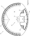
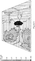
- Figures 1 to 3 show an apparatus 10 for reproducing a multi-channel audio signal.
- the apparatus 10 comprises a plurality of first loudspeakers 12 provided spaced around a first arc 14.
- Each of the first loudspeakers 12 face towards a listening zone 16 provided within the apparatus 10.
- the first loudspeakers 12 are preferably each substantially equidistant from the listening zone 16.
- the first arc 14 is preferably circular as shown in the drawings; however, elliptical or other arcuate curves may also be used.
- a plurality of second loudspeakers 18 are provided spaced around a second arc 20. Each of the second loudspeakers 18 faces towards the listening zone 16.
- a listener 22 is shown in Figure 1 in the listening zone 16 facing towards the first loudspeakers 12.
- the terms 'forward' and 'behind' are used relative to the listening zone 16 according to the orientation of the listener 22 shown in Figure 1 .
- the first loudspeakers 12 are positioned forward of the listening zone 16 and surround the forward 180° from the listening zone 16.
- the second loudspeakers 18 are positioned behind the listening zone 16.
- thirteen (13) first loudspeakers 12 and five (5) second loudspeakers 18 are used, though other quantities may be used. It is preferred that at the number of first and second loudspeakers should be at least thirteen, however.
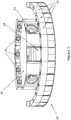
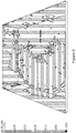
- Two low frequency drivers 24 are provided, to either side of and behind the listening zone 16 in an enclosure 26.
- the low frequency drivers 24 are configured as subwoofers.
- An amplifier 28 produces amplified signals from each channel in the audio signal.
- the audio signal has a separate channel for each loudspeaker 12, 18 and 24.
- the amplifier 28 provides a separate, amplified signal to each loudspeaker and to the subwoofers.
- the amplifier 28 is housed behind the listening zone 16 in the enclosure 26.
- the term amplifier 28 encompasses a multi-channel amplifier, multiple single-channel amplifiers, or a combination of both. Class D amplifiers are preferred for efficiency although other classes may be utilised.
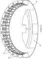
- the apparatus 10 has a base 30 on which the enclosure 26 is mounted.
- Each first loudspeaker 12 is provided in an enclosure 32 mounted to the base 30.
- Adjacent enclosures 32 are connected via plates 34 extending between their top surfaces. When mounted in this manner, the enclosures 32 form a continuous arc.
- the multi-channel audio signal consists of one or more sound objects. Each sound object is present in a plurality of channels of the audio signal as will be described in more detail below.
- each sound object is reproduced by one or more loudspeakers 12, 18.
- the sound from each loudspeaker converges on the listening zone 16. Since each loudspeaker 12 is substantially equidistant from the listening zone 16, sounds from adjacent loudspeakers 12 reproducing a sound object will add constructively at the listening zone 16.
- the SPL at a point spaced from the apparatus 10 is less than the SPL at the listening zone 16.
- the listening zone 16 is substantially equidistant from the loudspeakers 12 such that their sound outputs combine within the listening zone 16, while at other locations there will be different path lengths from each loudspeaker resulting in some destructive interference.
- the loudspeakers are located near and oriented towards the listening zone 16, while outside the apparatus 10 the average distance to the loudspeakers increases with increasing distance from the apparatus, resulting in a reduced SPL.
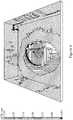
- Figures 4 to 6 show the results of SPL modelling in a 50m 2 room.
- the model was set to produce an SPL of 125dB at the listening zone, and the SPL throughout the room was then calculated.
- Figure 4 shows the SPL using the apparatus 10, in which the SPL at the walls of the room is at least 10 dB and up to 15-20 dB lower than the listening zone.
- Figure 5 shows the SPL using a traditional stereophonic arrangement. The SPL is greatest in this arrangement in the immediate vicinity of the loudspeakers and adjacent walls.
- Figure 6 shows the SPL in typical multi-channel systems with loudspeakers at the periphery of the room. As shown, the SPL throughout the room and the walls is relatively even.
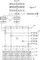
- the preferred method of producing an audio signal according to the embodiment involves three process stages applied to the track for each sound object - depth, width and pan - described below with reference to Figure 7 .
- Each track, or sound object signal is filtered via a low pass second order IIR filter 102, a low shelf second order IIR filter 104 and a high shelf second order IIR filter 106.
- These filters 102, 104 and 106 are applied in order to represent frequency variations that occur when the distance to a sound source increases.
- a gain stage 108 provided at the output of the filter 106, produces two depth-corrected output signals, referred to as direct and reverberant signals.
- filters 102, 104 and 106 and gain stage 108 are given below for a depth parameter d having a value between 0 and 1, where 0 is close to the listener and 1 is far away:
- the direct signal is passed to the Width stage described below.
- the reverberant signal is processed using an acoustic space simulator 110.
- the simulator 110 adds a configurable amount of reverberation. Balancing the amplitudes of the direct and reverberant signals, for example in the gain stage 108, provides an additional sense of depth.
- the simulator 110 uses a 1 input, n outputs algorithm. The n outputs have similar energy content, but are de-correlated using feedback delay networks with a different time constants for each output.
- n outputs enable them to be played by adjacent loudspeakers without affecting the listener 22's location of the sound object (which is located by the direct signal), whilst contributing to focussing acoustic energy at the listening zone 16 and providing a sense of depth.
- n ⁇ 13 and the n outputs may be mapped to all channels in the audio signal, with several of them being fed by the same output.
- the n outputs may be mapped to a subset of these channels using, for example, standard audio panning techniques.
- the direct signal from the depth stage is input to a fourth order crossover filter 112 that splits the signal into two bands: a low frequency (LF) part, and a high frequency (HF) part.
- the f a is approximately 500 Hz, but nothing prevents use of a lower frequency.
- the gain stages 114 apply gains to each of the k signals following a Gaussian distribution, whose standard deviation is controlled by an adjustable Width parameter. It is preferred that the gains of the gain stages 114 are normalised such that the sum of the k gain stage 114 outputs does not show any amplitude deviation from the HF input signal. The greater the value of the Width parameter, the more even the distribution of gains applied by the gain stages 114. This results in more control over the SPL outside the apparatus 10.
- k is an odd number, so that the middle of the k signals has a greater amplitude than the other of the k signals, which aids the listener 22 to locate the sound object.
- values of k other than 5 may be used.
- Each of the k signals passes through one of k all-pass FIR filters 116.
- Each FIR filter 116 alters the phase of the incoming signal with a spectral period T and a different initial phase compared to the other FIR filters 116 to produce one of k width signals, shown in Figure 7 at 118.
- the k width signals are de-correlated in phase due to the effect of the filters 116.
- Phase oscillation patterns such as sinusoids can be used, as well as other phase oscillation patterns.
- the effect of the Width processing stage is to produce k width signals with relative phase properties to enable their playback on k adjacent loudspeakers of the apparatus 10, without creating frequency cancellations in the listening zone 16.
- Figure 7 shows the LF part being summed to the middle signal of the k signals.
- the LF part could be applied to more than one of the k signals or follow the same gain/pan distribution as the HF part described above.
- the k width signals are each passed through a second order IIR low shelf filter 120 and gain stage 122 to produce k pan signals.
- the filter 120 provides a low-frequency gain correction that reduces the change in tonality of a sound object when panned across loudspeakers 12, 18.
- the gain of the filter 120 is -3dB when an object is equidistant to its two closest speakers.
- k pan signals are panned with an angular step corresponding to the angular distance between loudspeakers 12, 18 depending on the location of the sound object. This results in a set of signals, in k or k +1 of the channels in the audio signal, with similar energy content but de-correlated in phase. This contributes to focussing acoustic energy at the listening zone.
- the listener's ability to locate the sound object is unaffected: the listener will determine the location of a sound object based on the loudest apparent source of sound; the de-correlated signals to either side of the loudest signal for each sound object to not affect the listener's location of the sound object since de-correlated sound has no apparent location to a listener.
- This processing technique provides a sound stage with superior three-dimensionality, enhanced user ability to locate each sound object with precision, while maintaining a precise control of how the acoustic energy spreads outside the apparatus.
Landscapes
- Engineering & Computer Science (AREA)
- Physics & Mathematics (AREA)
- Acoustics & Sound (AREA)
- Signal Processing (AREA)
- Multimedia (AREA)
- Stereophonic System (AREA)
- Stereophonic Arrangements (AREA)
- Circuit For Audible Band Transducer (AREA)
Description
- The present invention relates to multi-channel audio systems.
- Multi-channel audio systems are distinguished from stereophonic audio systems by the number of channels of audio information and the corresponding number of loudspeakers used for playback. While stereophonic systems are characterised by two channels, common multi-channel audio systems have 5 or more channels.
- One of the goals of multi-channel audio systems is to provide a listener with the immersive experience of a conductor or an artist on stage.
- One factor important to such an experience is the ability to produce a realistic "sound stage" in which each object - for example musical instruments - within the produced sound is perceived by the listener to be originating from a position. Sound engineers place each sound object, typically at a virtual position between two channels, when mixing a multi-channel audio signal. The component of each sound object in the two channels is then determined using amplitude panning. When each channel is reproduced by a corresponding loudspeaker, the sound is perceived by the listener to originate from a location determined by the amplitude panning and the location of the loudspeakers to the listener.
- Another factor important to such an experience is the sound pressure level (SPL) the system is able to produce where the listener is positioned. Concerts and similar live performances can involve peak SPL above 120 dB.
- Most multi-channel audio systems have loudspeakers placed near the walls of a room, with the listener positioned towards the centre of the room. To provide an SPL of 120 dB at the listener with such an arrangement, the SPL at most positions along the walls of the room itself is greater than 120 dB, which is undesirable in residential environments.
- European patent publication
EP0966172A2 describes a method of synthesising an audio signal having left and right channels. - Chang Ji-Ho et al, "Experimental validation of sound field control with a circular double-array of loudspeakers", Journal of the Acoustical Society of America, Vol. 133, No. 4, April 2013, p2046-2054 describes a method of controlling sound fields with a circular double-layer array of loudspeakers.
- Ville Pulkki, "Uniform spreading of amplitude panned virtual sources", Proceedings of the 1999 IEEE Workshop on Applications of Signal Processing to Audio and Acoustics, 1999, p 187-190, describes a method to make the directional spread of amplitude panned virtual sources independent of their panning direction.
- International patent application
WO 2014/159272 A1 describes a method of synthesising a multi-channel audio signal for rendering an audio object with an apparent size. - We describe an apparatus for reproducing a multi-channel audio signal consisting of one or more sound objects in which each sound object is present in a plurality of channels, the apparatus comprising:
- A predetermined listening zone provided within the apparatus;
- A plurality of first loudspeakers provided spaced around a first arc forward of the listening zone, each of the first loudspeakers facing towards the listening zone and substantially equidistant therefrom;
- A plurality of second loudspeakers provided spaced around a second arc behind the listening zone, each of the second loudspeakers facing towards the listening zone;
- An amplifier arranged to produce an amplified signal from each channel in the audio signal, each amplified signal being provided to a corresponding first or second loudspeaker;
- Whereby each sound object is reproduced by one or more loudspeakers such that the SPL at a point spaced from the apparatus is less than the SPL at the listening zone.
- Preferably, the SPL at a point spaced from the apparatus the same distance as each first loudspeaker is spaced from the listening zone is 15 dB less than the SPL at the listening zone.
- Preferably, the number of first and second loudspeakers is at least 13, the number of first loudspeakers being greater than the number of second loudspeakers.
- Preferably, the multi-channel audio signal is produced by the method below.
- In accordance with a first aspect of the invention there is provided a method for producing a multi-channel audio signal from one or more sound object signals, comprising:
- For each sound object signal:
- Producing a plurality of de-correlated width signals from the sound object signal by duplicating a part of the sound object signal and applying gains to each of the duplicated signals, wherein the applied gains follow a Gaussian distribution;
- Processing the odd plurality of width signals to produce a plurality of pan signals, each pan signal being mapped to a channel;
- For each channel in the audio signal, combining the pan signals from each sound object for that channel.
- Preferably, the method further comprises the step of normalising the applied gains such that the amplitude of sum of the width signals is equal to the amplitude of the part of the sound object signal.
- Preferably, the Gaussian distribution follows a user-configurable standard deviation.
- Preferably, the step of producing a plurality of de-correlated width signals further comprises processing each sound object signal using a crossover filter to produce a low frequency part and a high frequency part, the plurality of de-correlated width signals being produced from the high frequency part.
- Preferably, an odd plurality of de-correlated width signals are produced, wherein the low frequency part is applied to a middle signal of the odd plurality of de-correlated width signals.
- Preferably, the method further comprises processing each sound object signal to produce a depth-corrected signal, and producing the plurality of de-correlated width signals from the depth-corrected signal.
- Preferably, each sound object signal is processed to produce two depth-corrected signals, a direct signal and a reverberant signal, wherein the plurality of de-correlated width signals are produced from the direct signal, and wherein the reverberant signal is processed to produce a plurality of de-correlated reverberant output signals, each de-correlated reverberant output signal being mapped to at least one channel in the audio signal.
- The invention will now be described, by way of example, with reference to the accompanying drawings, in which:
-
Figure 1 is a top view, partially cut away, of an apparatus for reproducing a multi-channel audio signal; -
Figure 2 is a perspective rear view of the apparatus inFigure 1 ; -
Figure 3 is a perspective front view of the apparatus inFigure 1 ; -
Figure 4 is shows room sound pressure levels (SPL) when the apparatus ofFigure 1 is in use; -
Figure 5 is shows comparable room SPL using conventional stereophonic loudspeakers and audio system; -
Figure 6 is shows comparable room SPL using conventional multi-channel loudspeakers and audio system; and -
Figure 7 is a signal processing diagram showing a method for producing a multi-channel audio signal according to one embodiment of the invention. -
Figures 1 to 3 show anapparatus 10 for reproducing a multi-channel audio signal. Theapparatus 10 comprises a plurality offirst loudspeakers 12 provided spaced around afirst arc 14. Each of thefirst loudspeakers 12 face towards alistening zone 16 provided within theapparatus 10. Thefirst loudspeakers 12 are preferably each substantially equidistant from thelistening zone 16. Thefirst arc 14 is preferably circular as shown in the drawings; however, elliptical or other arcuate curves may also be used. - A plurality of
second loudspeakers 18 are provided spaced around a second arc 20. Each of thesecond loudspeakers 18 faces towards thelistening zone 16. - A
listener 22 is shown inFigure 1 in thelistening zone 16 facing towards thefirst loudspeakers 12. Throughout the specification, the terms 'forward' and 'behind' are used relative to thelistening zone 16 according to the orientation of thelistener 22 shown inFigure 1 . - As seen in
Figure 1 , thefirst loudspeakers 12 are positioned forward of thelistening zone 16 and surround the forward 180° from thelistening zone 16. Thesecond loudspeakers 18 are positioned behind thelistening zone 16. In the embodiment, thirteen (13)first loudspeakers 12 and five (5)second loudspeakers 18 are used, though other quantities may be used. It is preferred that at the number of first and second loudspeakers should be at least thirteen, however. - Two
low frequency drivers 24 are provided, to either side of and behind thelistening zone 16 in anenclosure 26. Thelow frequency drivers 24 are configured as subwoofers. - An
amplifier 28 produces amplified signals from each channel in the audio signal. Preferably, the audio signal has a separate channel for eachloudspeaker amplifier 28 provides a separate, amplified signal to each loudspeaker and to the subwoofers. Theamplifier 28 is housed behind the listeningzone 16 in theenclosure 26. Theterm amplifier 28 encompasses a multi-channel amplifier, multiple single-channel amplifiers, or a combination of both. Class D amplifiers are preferred for efficiency although other classes may be utilised. - The
apparatus 10 has a base 30 on which theenclosure 26 is mounted. Eachfirst loudspeaker 12 is provided in anenclosure 32 mounted to thebase 30.Adjacent enclosures 32 are connected viaplates 34 extending between their top surfaces. When mounted in this manner, theenclosures 32 form a continuous arc. - The multi-channel audio signal consists of one or more sound objects. Each sound object is present in a plurality of channels of the audio signal as will be described in more detail below.
- When the audio signal is reproduced by the
apparatus 10, each sound object is reproduced by one ormore loudspeakers zone 16. Since eachloudspeaker 12 is substantially equidistant from the listeningzone 16, sounds fromadjacent loudspeakers 12 reproducing a sound object will add constructively at the listeningzone 16. - When the
apparatus 10 reproduces the audio signal, the SPL at a point spaced from theapparatus 10 is less than the SPL at the listeningzone 16. Two factors contribute to this effect. First, the listeningzone 16 is substantially equidistant from theloudspeakers 12 such that their sound outputs combine within the listeningzone 16, while at other locations there will be different path lengths from each loudspeaker resulting in some destructive interference. Secondly, the loudspeakers are located near and oriented towards the listeningzone 16, while outside theapparatus 10 the average distance to the loudspeakers increases with increasing distance from the apparatus, resulting in a reduced SPL. -
Figures 4 to 6 show the results of SPL modelling in a 50m2 room. In each of these figures, the model was set to produce an SPL of 125dB at the listening zone, and the SPL throughout the room was then calculated. -
Figure 4 shows the SPL using theapparatus 10, in which the SPL at the walls of the room is at least 10 dB and up to 15-20 dB lower than the listening zone.Figure 5 shows the SPL using a traditional stereophonic arrangement. The SPL is greatest in this arrangement in the immediate vicinity of the loudspeakers and adjacent walls.Figure 6 shows the SPL in typical multi-channel systems with loudspeakers at the periphery of the room. As shown, the SPL throughout the room and the walls is relatively even. - Production of conventional audio signals involves arranging monaural tracks, with each track representing a sound object; such tracks are also referred to as sound object signals. For a studio recording, there would be a track for each instrument and vocal singer. The sound engineer arranges these tracks, adjusting relative amplitudes. The tracks are then mixed together and reduced to the number of channels using amplitude panning techniques.
- The preferred method of producing an audio signal according to the embodiment involves three process stages applied to the track for each sound object - depth, width and pan - described below with reference to
Figure 7 . - Each track, or sound object signal, is filtered via a low pass second
order IIR filter 102, a low shelf secondorder IIR filter 104 and a high shelf secondorder IIR filter 106. Thesefilters gain stage 108, provided at the output of thefilter 106, produces two depth-corrected output signals, referred to as direct and reverberant signals. - Examples of
filters stage 108 are given below for a depth parameter d having a value between 0 and 1, where 0 is close to the listener and 1 is far away: -
Filter 102 may be a Butterworth 2nd order low pass filter with a cut-off frequency fc, where fc = 20 kHz if d <= 0.2, and fc = 20 kHz - 15 kHz * (d-0.2)/0.8 if d > 0.2. -
Filter 104 may be a low Shelf second order IIR filter with a corner frequency of 80 Hz, Q = 0.5, and gain(dB) = 3.0 * (1.0 - 5*d)2 if d <= 0.2, and gain(dB) = -6.0 * ((d - 0.2)/0.8)2 if d > 0.2. -
Filter 106 may be a high shelf second order IIR filter with a corner frequency of 16 kHz, Q = 0.5, and gain(dB) = 6.0 * (1.0 - 5*d)2 if d <= 0.2, and gain(dB) = 0.0 if d > 0.2. -
Gain stage 108 may be a simple gain control where gain(dB) = 3.0 * (1.0 - 5*d)2 if d <= 0.2, and gain(dB) = -12.0 * ((d - 0.2)/0.8)2 if d > 0.2. - It should be appreciated that the above values are one example only, and other values may be used.
- The direct signal is passed to the Width stage described below. The reverberant signal is processed using an
acoustic space simulator 110. Thesimulator 110 adds a configurable amount of reverberation. Balancing the amplitudes of the direct and reverberant signals, for example in thegain stage 108, provides an additional sense of depth. Thesimulator 110 uses a 1 input, n outputs algorithm. The n outputs have similar energy content, but are de-correlated using feedback delay networks with a different time constants for each output. - The de-correlated nature of the n outputs enables them to be played by adjacent loudspeakers without affecting the
listener 22's location of the sound object (which is located by the direct signal), whilst contributing to focussing acoustic energy at the listeningzone 16 and providing a sense of depth. Typically, n < 13 and the n outputs may be mapped to all channels in the audio signal, with several of them being fed by the same output. Alternatively, the n outputs may be mapped to a subset of these channels using, for example, standard audio panning techniques. - The direct signal from the depth stage is input to a fourth
order crossover filter 112 that splits the signal into two bands: a low frequency (LF) part, and a high frequency (HF) part. The crossover frequency of thefilter 112 is chosen so that it is below the spatial aliasing frequency fa=2c/dspeaker, where fa is the spatial aliasing frequency, c is the speed of propagation of sound in air, and dspeaker is the distance between the centers of two adjacent speakers. In the embodiment, the fa is approximately 500 Hz, but nothing prevents use of a lower frequency. - The HF part of the signal is passed through k parallel gain stages 114, to produce k signals, with
Figure 7 drawn for the instance of k=5. The gain stages 114 apply gains to each of the k signals following a Gaussian distribution, whose standard deviation is controlled by an adjustable Width parameter. It is preferred that the gains of the gain stages 114 are normalised such that the sum of thek gain stage 114 outputs does not show any amplitude deviation from the HF input signal. The greater the value of the Width parameter, the more even the distribution of gains applied by the gain stages 114. This results in more control over the SPL outside theapparatus 10. - It is preferred that k is an odd number, so that the middle of the k signals has a greater amplitude than the other of the k signals, which aids the
listener 22 to locate the sound object. In other embodiments, values of k other than 5 may be used. - Each of the k signals passes through one of k all-pass FIR filters 116. Each
FIR filter 116 alters the phase of the incoming signal with a spectral period T and a different initial phase compared to the other FIR filters 116 to produce one of k width signals, shown inFigure 7 at 118. The k width signals are de-correlated in phase due to the effect of thefilters 116. Phase oscillation patterns such as sinusoids can be used, as well as other phase oscillation patterns. - The effect of the Width processing stage is to produce k width signals with relative phase properties to enable their playback on k adjacent loudspeakers of the
apparatus 10, without creating frequency cancellations in the listeningzone 16. -
Figure 7 shows the LF part being summed to the middle signal of the k signals. In other embodiments, the LF part could be applied to more than one of the k signals or follow the same gain/pan distribution as the HF part described above. - The k width signals are each passed through a second order IIR
low shelf filter 120 and gainstage 122 to produce k pan signals. Thefilter 120 provides a low-frequency gain correction that reduces the change in tonality of a sound object when panned acrossloudspeakers filter 120 is -3dB when an object is equidistant to its two closest speakers. - Next, standard amplitude panning techniques are used to map the k pan signals to channels in the audio signal. The k pan signals are panned with an angular step corresponding to the angular distance between
loudspeakers - The above processing is performed for each sound object, and the outputs combined for channel to produce the multi-channel audio signal. This processing technique provides a sound stage with superior three-dimensionality, enhanced user ability to locate each sound object with precision, while maintaining a precise control of how the acoustic energy spreads outside the apparatus.
Claims (7)
- A method for producing a multi-channel audio signal from one or more sound object signals, comprising:For each sound object signal:
Producing a plurality of de-correlated width signals from the sound object signal by duplicating a part of the sound object signal; Processing the plurality of width signals to produce a plurality of pan signals,each pan signal being mapped to at least one channel;For each channel in the audio signal, combining the pan signals from each sound object for that channel;characterised in that for each sound object signal, the plurality of de-correlated width signals is produced by applying gains to each of the duplicated signals, wherein the applied gains follow a Gaussian distribution. - The method of claim 1, further comprising the step of normalising the applied gains such that the amplitude of sum of the width signals is equal to the amplitude of the part of the sound object signal;
- The method of claim 1 or 2, wherein the Gaussian distribution follows a user-configurable standard deviation.
- The method of claim 1, wherein the step of producing a plurality of de-correlated width signals further comprises processing each sound object signal using a crossover filter to produce a low frequency part and a high frequency part, the plurality of de-correlated width signals being produced from the high frequency part.
- The method of claim 4, wherein for each audio object signal an odd plurality of de-correlated width signals are produced, wherein the low frequency part is applied to a middle signal having the greatest amplitude of the odd plurality of de-correlated width signals.
- The method of claim 1, further comprising processing each sound object signal to produce a depth-corrected signal, and producing the plurality of de-correlated width signals from the depth-corrected signal.
- The method of claim 6, wherein each sound object signal is processed to produce two depth-corrected signals, a direct signal and a reverberant signal, wherein the plurality of de-correlated width signals are produced from the direct signal, and wherein the reverberant signal is processed to produce a plurality of de-correlated reverberant output signals having similar energy content, each de-correlated reverberant output signal being mapped to at least one channel in the audio signal.
Priority Applications (15)
| Application Number | Priority Date | Filing Date | Title |
|---|---|---|---|
| DK15165526.3T DK3089477T3 (en) | 2015-04-28 | 2015-04-28 | AN APPARATUS FOR REPRESENTING A MULTI CHANNEL SIGNAL AND A METHOD FOR MAKING A MULTI CHANNEL SIGNAL |
| PL15165526T PL3089477T3 (en) | 2015-04-28 | 2015-04-28 | An apparatus for reproducing a multi-channel audio signal and a method for producing a multi-channel audio signal |
| PT15165526T PT3089477T (en) | 2015-04-28 | 2015-04-28 | An apparatus for reproducing a multi-channel audio signal and a method for producing a multi-channel audio signal |
| EP15165526.3A EP3089477B1 (en) | 2015-04-28 | 2015-04-28 | An apparatus for reproducing a multi-channel audio signal and a method for producing a multi-channel audio signal |
| ES15165526.3T ES2686275T3 (en) | 2015-04-28 | 2015-04-28 | An apparatus for reproducing a multichannel audio signal and a method for producing a multichannel audio signal |
| US15/570,608 US10939223B2 (en) | 2015-04-28 | 2016-04-28 | Apparatus for reproducing a multi-channel audio signal and a method for producing a multi channel audio signal |
| BR112017023292-8A BR112017023292A2 (en) | 2015-04-28 | 2016-04-28 | equipment for reproducing a multichannel audio signal, and method for producing a multichannel audio signal from one or more sound object signals |
| JP2018507774A JP2018518923A (en) | 2015-04-28 | 2016-04-28 | Apparatus for reproducing multi-channel audio signal and method for generating multi-channel audio signal |
| CA2984077A CA2984077A1 (en) | 2015-04-28 | 2016-04-28 | An apparatus for reproducing a multi-channel audio signal and a method for producing a multi-channel audio signal |
| RU2020109884A RU2020109884A (en) | 2015-04-28 | 2016-04-28 | DEVICE FOR PLAYING MULTI-CHANNEL AUDIO AND METHOD FOR PRODUCING MULTI-CHANNEL AUDIO |
| AU2016254322A AU2016254322B2 (en) | 2015-04-28 | 2016-04-28 | An apparatus for reproducing a multi-channel audio signal and a method for producing a multi channel audio signal |
| CN201680024455.4A CN107534813B (en) | 2015-04-28 | 2016-04-28 | Apparatus for reproducing multi-channel audio signal and method of generating multi-channel audio signal |
| PCT/EP2016/059561 WO2016174174A1 (en) | 2015-04-28 | 2016-04-28 | An apparatus for reproducing a multi-channel audio signal and a method for producing a multi channel audio signal |
| RU2017140643A RU2722314C2 (en) | 2015-04-28 | 2016-04-28 | Apparatus for reproducing a multichannel audio signal and a method of generating a multichannel audio signal |
| HRP20181407TT HRP20181407T1 (en) | 2015-04-28 | 2018-09-03 | An apparatus for reproducing a multi-channel audio signal and a method for producing a multi-channel audio signal |
Applications Claiming Priority (1)
| Application Number | Priority Date | Filing Date | Title |
|---|---|---|---|
| EP15165526.3A EP3089477B1 (en) | 2015-04-28 | 2015-04-28 | An apparatus for reproducing a multi-channel audio signal and a method for producing a multi-channel audio signal |
Publications (2)
| Publication Number | Publication Date |
|---|---|
| EP3089477A1 EP3089477A1 (en) | 2016-11-02 |
| EP3089477B1 true EP3089477B1 (en) | 2018-06-06 |
Family
ID=53015641
Family Applications (1)
| Application Number | Title | Priority Date | Filing Date |
|---|---|---|---|
| EP15165526.3A Active EP3089477B1 (en) | 2015-04-28 | 2015-04-28 | An apparatus for reproducing a multi-channel audio signal and a method for producing a multi-channel audio signal |
Country Status (14)
| Country | Link |
|---|---|
| US (1) | US10939223B2 (en) |
| EP (1) | EP3089477B1 (en) |
| JP (1) | JP2018518923A (en) |
| CN (1) | CN107534813B (en) |
| AU (1) | AU2016254322B2 (en) |
| BR (1) | BR112017023292A2 (en) |
| CA (1) | CA2984077A1 (en) |
| DK (1) | DK3089477T3 (en) |
| ES (1) | ES2686275T3 (en) |
| HR (1) | HRP20181407T1 (en) |
| PL (1) | PL3089477T3 (en) |
| PT (1) | PT3089477T (en) |
| RU (2) | RU2722314C2 (en) |
| WO (1) | WO2016174174A1 (en) |
Families Citing this family (1)
| Publication number | Priority date | Publication date | Assignee | Title |
|---|---|---|---|---|
| CA3054237A1 (en) * | 2017-01-27 | 2018-08-02 | Auro Technologies Nv | Processing method and system for panning audio objects |
Citations (1)
| Publication number | Priority date | Publication date | Assignee | Title |
|---|---|---|---|---|
| WO2014159272A1 (en) * | 2013-03-28 | 2014-10-02 | Dolby Laboratories Licensing Corporation | Rendering of audio objects with apparent size to arbitrary loudspeaker layouts |
Family Cites Families (20)
| Publication number | Priority date | Publication date | Assignee | Title |
|---|---|---|---|---|
| US3842203A (en) * | 1972-06-30 | 1974-10-15 | J Weisberg | Public address system with horn speakers arrayed around and facing inward toward a common point |
| US5610986A (en) | 1994-03-07 | 1997-03-11 | Miles; Michael T. | Linear-matrix audio-imaging system and image analyzer |
| US5459790A (en) * | 1994-03-08 | 1995-10-17 | Sonics Associates, Ltd. | Personal sound system with virtually positioned lateral speakers |
| JPH1014000A (en) * | 1996-06-26 | 1998-01-16 | Matsushita Electric Ind Co Ltd | Acoustic reproduction device |
| GB2343347B (en) * | 1998-06-20 | 2002-12-31 | Central Research Lab Ltd | A method of synthesising an audio signal |
| JP2001134272A (en) * | 1999-11-08 | 2001-05-18 | Takahiro Yamashita | Acoustic environment bodily sensing equipment |
| US6904157B2 (en) * | 2000-08-10 | 2005-06-07 | Shima System Co., Ltd. | Structure around a speaker unit and applied electric or electronic apparatus thereof |
| US7310604B1 (en) * | 2000-10-23 | 2007-12-18 | Analog Devices, Inc. | Statistical sound event modeling system and methods |
| DE10309517B4 (en) * | 2003-03-05 | 2006-04-13 | Reissig, Sergej, Dr.-Ing. | speaker |
| US7684574B2 (en) * | 2003-05-27 | 2010-03-23 | Harman International Industries, Incorporated | Reflective loudspeaker array |
| WO2005086527A1 (en) * | 2004-03-08 | 2005-09-15 | Ilario Carmen Deciccia | An improved audio arrangement |
| TWI245258B (en) * | 2004-08-26 | 2005-12-11 | Via Tech Inc | Method and related apparatus for generating audio reverberation effect |
| JP4841495B2 (en) * | 2007-04-16 | 2011-12-21 | ソニー株式会社 | Sound reproduction system and speaker device |
| RU2011147119A (en) * | 2009-04-21 | 2013-05-27 | Конинклейке Филипс Электроникс Н.В. | AUDIO SYNTHESIS |
| US20130279723A1 (en) * | 2010-09-06 | 2013-10-24 | Cambridge Mechatronics Limited | Array loudspeaker system |
| KR102024284B1 (en) * | 2012-03-14 | 2019-09-23 | 방 앤드 오루프센 에이/에스 | A method of applying a combined or hybrid sound -field control strategy |
| US9332373B2 (en) * | 2012-05-31 | 2016-05-03 | Dts, Inc. | Audio depth dynamic range enhancement |
| US9445197B2 (en) * | 2013-05-07 | 2016-09-13 | Bose Corporation | Signal processing for a headrest-based audio system |
| US9973851B2 (en) * | 2014-12-01 | 2018-05-15 | Sonos, Inc. | Multi-channel playback of audio content |
| WO2016172111A1 (en) * | 2015-04-20 | 2016-10-27 | Dolby Laboratories Licensing Corporation | Processing audio data to compensate for partial hearing loss or an adverse hearing environment |
-
2015
- 2015-04-28 ES ES15165526.3T patent/ES2686275T3/en active Active
- 2015-04-28 PL PL15165526T patent/PL3089477T3/en unknown
- 2015-04-28 EP EP15165526.3A patent/EP3089477B1/en active Active
- 2015-04-28 DK DK15165526.3T patent/DK3089477T3/en active
- 2015-04-28 PT PT15165526T patent/PT3089477T/en unknown
-
2016
- 2016-04-28 CA CA2984077A patent/CA2984077A1/en not_active Abandoned
- 2016-04-28 CN CN201680024455.4A patent/CN107534813B/en active Active
- 2016-04-28 RU RU2017140643A patent/RU2722314C2/en active
- 2016-04-28 BR BR112017023292-8A patent/BR112017023292A2/en active Search and Examination
- 2016-04-28 WO PCT/EP2016/059561 patent/WO2016174174A1/en active Application Filing
- 2016-04-28 US US15/570,608 patent/US10939223B2/en active Active
- 2016-04-28 RU RU2020109884A patent/RU2020109884A/en unknown
- 2016-04-28 JP JP2018507774A patent/JP2018518923A/en active Pending
- 2016-04-28 AU AU2016254322A patent/AU2016254322B2/en not_active Ceased
-
2018
- 2018-09-03 HR HRP20181407TT patent/HRP20181407T1/en unknown
Patent Citations (1)
| Publication number | Priority date | Publication date | Assignee | Title |
|---|---|---|---|---|
| WO2014159272A1 (en) * | 2013-03-28 | 2014-10-02 | Dolby Laboratories Licensing Corporation | Rendering of audio objects with apparent size to arbitrary loudspeaker layouts |
Also Published As
| Publication number | Publication date |
|---|---|
| RU2020109884A (en) | 2020-05-12 |
| WO2016174174A1 (en) | 2016-11-03 |
| DK3089477T3 (en) | 2018-09-17 |
| US10939223B2 (en) | 2021-03-02 |
| EP3089477A1 (en) | 2016-11-02 |
| CN107534813B (en) | 2020-09-11 |
| CN107534813A (en) | 2018-01-02 |
| PT3089477T (en) | 2018-10-24 |
| US20180288555A1 (en) | 2018-10-04 |
| RU2017140643A (en) | 2019-05-28 |
| RU2722314C2 (en) | 2020-05-28 |
| AU2016254322B2 (en) | 2020-07-23 |
| CA2984077A1 (en) | 2016-11-03 |
| ES2686275T3 (en) | 2018-10-17 |
| JP2018518923A (en) | 2018-07-12 |
| HRP20181407T1 (en) | 2018-10-19 |
| RU2017140643A3 (en) | 2019-07-17 |
| AU2016254322A1 (en) | 2017-11-16 |
| BR112017023292A2 (en) | 2018-08-14 |
| PL3089477T3 (en) | 2018-11-30 |
Similar Documents
| Publication | Publication Date | Title |
|---|---|---|
| EP1713306B1 (en) | Speaker apparatus | |
| KR101177853B1 (en) | Audio signal reproduction apparatus and method thereof | |
| KR100458021B1 (en) | Multi-channel audio enhancement system for use in recording and playback and methods for providing same | |
| KR101297300B1 (en) | Front Surround system and method for processing signal using speaker array | |
| US9374640B2 (en) | Method and system for optimizing center channel performance in a single enclosure multi-element loudspeaker line array | |
| JP2001511995A (en) | Audio signal processing method | |
| JP2018514160A (en) | Difference sound playback | |
| KR20190091825A (en) | Method for up-mixing stereo audio to binaural audio and apparatus using the same | |
| TW202245483A (en) | Apparatus and method for generating a first control signal and a second control signal by using a linearization and/or a bandwidth extension | |
| US6925186B2 (en) | Ambient sound audio system | |
| US20040234093A1 (en) | Sound output system | |
| EP3089477B1 (en) | An apparatus for reproducing a multi-channel audio signal and a method for producing a multi-channel audio signal | |
| US20180262859A1 (en) | Method for sound reproduction in reflection environments, in particular in listening rooms | |
| KR100386919B1 (en) | Karaoke Apparatus | |
| JP2004350173A (en) | Sound image reproducing apparatus and stereophonic sound image reproducing apparatus | |
| TW202249498A (en) | Apparatus and method for generating a control signal for a sound generator or for generating an extended multi-channel audio signal by using a similarity analysis | |
| US10313794B2 (en) | Speaker system | |
| CN102970640A (en) | Speaker apparatus | |
| JP6699280B2 (en) | Sound reproduction device | |
| Corteel et al. | Spatial sound reinforcement using Wave Field Synthesis. A case study at the Institut du Monde Arabe | |
| JP2010016573A (en) | Crosstalk canceling stereo speaker system | |
| JP2022117950A (en) | System and method for providing three-dimensional immersive sound | |
| JP2021500790A (en) | Spatial arrangement of sound diffuser | |
| JP2014045479A (en) | Acoustic processing device | |
| JP2006157210A (en) | Multichannel sound field processing apparatus |
Legal Events
| Date | Code | Title | Description |
|---|---|---|---|
| PUAI | Public reference made under article 153(3) epc to a published international application that has entered the european phase |
Free format text: ORIGINAL CODE: 0009012 |
|
| AK | Designated contracting states |
Kind code of ref document: A1 Designated state(s): AL AT BE BG CH CY CZ DE DK EE ES FI FR GB GR HR HU IE IS IT LI LT LU LV MC MK MT NL NO PL PT RO RS SE SI SK SM TR |
|
| AX | Request for extension of the european patent |
Extension state: BA ME |
|
| STAA | Information on the status of an ep patent application or granted ep patent |
Free format text: STATUS: REQUEST FOR EXAMINATION WAS MADE |
|
| 17P | Request for examination filed |
Effective date: 20170331 |
|
| RBV | Designated contracting states (corrected) |
Designated state(s): AL AT BE BG CH CY CZ DE DK EE ES FI FR GB GR HR HU IE IS IT LI LT LU LV MC MK MT NL NO PL PT RO RS SE SI SK SM TR |
|
| GRAP | Despatch of communication of intention to grant a patent |
Free format text: ORIGINAL CODE: EPIDOSNIGR1 |
|
| STAA | Information on the status of an ep patent application or granted ep patent |
Free format text: STATUS: GRANT OF PATENT IS INTENDED |
|
| RIC1 | Information provided on ipc code assigned before grant |
Ipc: H04R 5/02 20060101AFI20180109BHEP Ipc: H04S 7/00 20060101ALN20180109BHEP Ipc: H04S 3/00 20060101ALI20180109BHEP Ipc: H04R 27/00 20060101ALN20180109BHEP |
|
| INTG | Intention to grant announced |
Effective date: 20180131 |
|
| GRAS | Grant fee paid |
Free format text: ORIGINAL CODE: EPIDOSNIGR3 |
|
| GRAA | (expected) grant |
Free format text: ORIGINAL CODE: 0009210 |
|
| STAA | Information on the status of an ep patent application or granted ep patent |
Free format text: STATUS: THE PATENT HAS BEEN GRANTED |
|
| AK | Designated contracting states |
Kind code of ref document: B1 Designated state(s): AL AT BE BG CH CY CZ DE DK EE ES FI FR GB GR HR HU IE IS IT LI LT LU LV MC MK MT NL NO PL PT RO RS SE SI SK SM TR |
|
| REG | Reference to a national code |
Ref country code: GB Ref legal event code: FG4D |
|
| REG | Reference to a national code |
Ref country code: CH Ref legal event code: EP Ref country code: AT Ref legal event code: REF Ref document number: 1007343 Country of ref document: AT Kind code of ref document: T Effective date: 20180615 |
|
| REG | Reference to a national code |
Ref country code: IE Ref legal event code: FG4D |
|
| REG | Reference to a national code |
Ref country code: DE Ref legal event code: R096 Ref document number: 602015011612 Country of ref document: DE |
|
| REG | Reference to a national code |
Ref country code: HR Ref legal event code: TUEP Ref document number: P20181407 Country of ref document: HR |
|
| REG | Reference to a national code |
Ref country code: RO Ref legal event code: EPE |
|
| REG | Reference to a national code |
Ref country code: CH Ref legal event code: NV Representative=s name: NOVAGRAAF INTERNATIONAL SA, CH |
|
| REG | Reference to a national code |
Ref country code: DK Ref legal event code: T3 Effective date: 20180910 |
|
| REG | Reference to a national code |
Ref country code: NL Ref legal event code: FP |
|
| REG | Reference to a national code |
Ref country code: SE Ref legal event code: TRGR |
|
| REG | Reference to a national code |
Ref country code: ES Ref legal event code: FG2A Ref document number: 2686275 Country of ref document: ES Kind code of ref document: T3 Effective date: 20181017 |
|
| REG | Reference to a national code |
Ref country code: HR Ref legal event code: T1PR Ref document number: P20181407 Country of ref document: HR |
|
| REG | Reference to a national code |
Ref country code: PT Ref legal event code: SC4A Ref document number: 3089477 Country of ref document: PT Date of ref document: 20181024 Kind code of ref document: T Free format text: AVAILABILITY OF NATIONAL TRANSLATION Effective date: 20180921 |
|
| REG | Reference to a national code |
Ref country code: LT Ref legal event code: MG4D |
|
| REG | Reference to a national code |
Ref country code: NO Ref legal event code: T2 Effective date: 20180606 |
|
| PG25 | Lapsed in a contracting state [announced via postgrant information from national office to epo] |
Ref country code: CY Free format text: LAPSE BECAUSE OF FAILURE TO SUBMIT A TRANSLATION OF THE DESCRIPTION OR TO PAY THE FEE WITHIN THE PRESCRIBED TIME-LIMIT Effective date: 20180606 Ref country code: LT Free format text: LAPSE BECAUSE OF FAILURE TO SUBMIT A TRANSLATION OF THE DESCRIPTION OR TO PAY THE FEE WITHIN THE PRESCRIBED TIME-LIMIT Effective date: 20180606 Ref country code: BG Free format text: LAPSE BECAUSE OF FAILURE TO SUBMIT A TRANSLATION OF THE DESCRIPTION OR TO PAY THE FEE WITHIN THE PRESCRIBED TIME-LIMIT Effective date: 20180906 |
|
| PG25 | Lapsed in a contracting state [announced via postgrant information from national office to epo] |
Ref country code: RS Free format text: LAPSE BECAUSE OF FAILURE TO SUBMIT A TRANSLATION OF THE DESCRIPTION OR TO PAY THE FEE WITHIN THE PRESCRIBED TIME-LIMIT Effective date: 20180606 Ref country code: LV Free format text: LAPSE BECAUSE OF FAILURE TO SUBMIT A TRANSLATION OF THE DESCRIPTION OR TO PAY THE FEE WITHIN THE PRESCRIBED TIME-LIMIT Effective date: 20180606 Ref country code: GR Free format text: LAPSE BECAUSE OF FAILURE TO SUBMIT A TRANSLATION OF THE DESCRIPTION OR TO PAY THE FEE WITHIN THE PRESCRIBED TIME-LIMIT Effective date: 20180907 |
|
| PG25 | Lapsed in a contracting state [announced via postgrant information from national office to epo] |
Ref country code: EE Free format text: LAPSE BECAUSE OF FAILURE TO SUBMIT A TRANSLATION OF THE DESCRIPTION OR TO PAY THE FEE WITHIN THE PRESCRIBED TIME-LIMIT Effective date: 20180606 Ref country code: IS Free format text: LAPSE BECAUSE OF FAILURE TO SUBMIT A TRANSLATION OF THE DESCRIPTION OR TO PAY THE FEE WITHIN THE PRESCRIBED TIME-LIMIT Effective date: 20181006 |
|
| REG | Reference to a national code |
Ref country code: SK Ref legal event code: T3 Ref document number: E 28708 Country of ref document: SK |
|
| PG25 | Lapsed in a contracting state [announced via postgrant information from national office to epo] |
Ref country code: SM Free format text: LAPSE BECAUSE OF FAILURE TO SUBMIT A TRANSLATION OF THE DESCRIPTION OR TO PAY THE FEE WITHIN THE PRESCRIBED TIME-LIMIT Effective date: 20180606 |
|
| REG | Reference to a national code |
Ref country code: DE Ref legal event code: R097 Ref document number: 602015011612 Country of ref document: DE |
|
| PLBE | No opposition filed within time limit |
Free format text: ORIGINAL CODE: 0009261 |
|
| STAA | Information on the status of an ep patent application or granted ep patent |
Free format text: STATUS: NO OPPOSITION FILED WITHIN TIME LIMIT |
|
| 26N | No opposition filed |
Effective date: 20190307 |
|
| REG | Reference to a national code |
Ref country code: HR Ref legal event code: ODRP Ref document number: P20181407 Country of ref document: HR Payment date: 20190423 Year of fee payment: 5 |
|
| PG25 | Lapsed in a contracting state [announced via postgrant information from national office to epo] |
Ref country code: SI Free format text: LAPSE BECAUSE OF FAILURE TO SUBMIT A TRANSLATION OF THE DESCRIPTION OR TO PAY THE FEE WITHIN THE PRESCRIBED TIME-LIMIT Effective date: 20180606 |
|
| PG25 | Lapsed in a contracting state [announced via postgrant information from national office to epo] |
Ref country code: AL Free format text: LAPSE BECAUSE OF FAILURE TO SUBMIT A TRANSLATION OF THE DESCRIPTION OR TO PAY THE FEE WITHIN THE PRESCRIBED TIME-LIMIT Effective date: 20180606 |
|
| PG25 | Lapsed in a contracting state [announced via postgrant information from national office to epo] |
Ref country code: LU Free format text: LAPSE BECAUSE OF NON-PAYMENT OF DUE FEES Effective date: 20190428 Ref country code: MC Free format text: LAPSE BECAUSE OF FAILURE TO SUBMIT A TRANSLATION OF THE DESCRIPTION OR TO PAY THE FEE WITHIN THE PRESCRIBED TIME-LIMIT Effective date: 20180606 |
|
| REG | Reference to a national code |
Ref country code: HR Ref legal event code: ODRP Ref document number: P20181407 Country of ref document: HR Payment date: 20200421 Year of fee payment: 6 |
|
| PGFP | Annual fee paid to national office [announced via postgrant information from national office to epo] |
Ref country code: PT Payment date: 20200423 Year of fee payment: 6 Ref country code: CH Payment date: 20200429 Year of fee payment: 6 Ref country code: FI Payment date: 20200417 Year of fee payment: 6 Ref country code: NO Payment date: 20200423 Year of fee payment: 6 Ref country code: CZ Payment date: 20200422 Year of fee payment: 6 Ref country code: TR Payment date: 20200427 Year of fee payment: 6 Ref country code: RO Payment date: 20200427 Year of fee payment: 6 Ref country code: NL Payment date: 20200429 Year of fee payment: 6 Ref country code: DK Payment date: 20200423 Year of fee payment: 6 Ref country code: IE Payment date: 20200423 Year of fee payment: 6 |
|
| REG | Reference to a national code |
Ref country code: AT Ref legal event code: UEP Ref document number: 1007343 Country of ref document: AT Kind code of ref document: T Effective date: 20180606 |
|
| PGFP | Annual fee paid to national office [announced via postgrant information from national office to epo] |
Ref country code: PL Payment date: 20200417 Year of fee payment: 6 Ref country code: SE Payment date: 20200429 Year of fee payment: 6 Ref country code: HR Payment date: 20200421 Year of fee payment: 6 Ref country code: SK Payment date: 20200420 Year of fee payment: 6 Ref country code: BE Payment date: 20200429 Year of fee payment: 6 |
|
| PGFP | Annual fee paid to national office [announced via postgrant information from national office to epo] |
Ref country code: AT Payment date: 20200421 Year of fee payment: 6 |
|
| PG25 | Lapsed in a contracting state [announced via postgrant information from national office to epo] |
Ref country code: MT Free format text: LAPSE BECAUSE OF FAILURE TO SUBMIT A TRANSLATION OF THE DESCRIPTION OR TO PAY THE FEE WITHIN THE PRESCRIBED TIME-LIMIT Effective date: 20180606 Ref country code: HU Free format text: LAPSE BECAUSE OF FAILURE TO SUBMIT A TRANSLATION OF THE DESCRIPTION OR TO PAY THE FEE WITHIN THE PRESCRIBED TIME-LIMIT; INVALID AB INITIO Effective date: 20150428 |
|
| PGFP | Annual fee paid to national office [announced via postgrant information from national office to epo] |
Ref country code: ES Payment date: 20210519 Year of fee payment: 7 |
|
| REG | Reference to a national code |
Ref country code: FI Ref legal event code: MAE |
|
| REG | Reference to a national code |
Ref country code: HR Ref legal event code: PBON Ref document number: P20181407 Country of ref document: HR Effective date: 20210428 |
|
| REG | Reference to a national code |
Ref country code: DK Ref legal event code: EBP Effective date: 20210430 |
|
| REG | Reference to a national code |
Ref country code: NO Ref legal event code: MMEP |
|
| REG | Reference to a national code |
Ref country code: SE Ref legal event code: EUG |
|
| REG | Reference to a national code |
Ref country code: NL Ref legal event code: MM Effective date: 20210501 |
|
| REG | Reference to a national code |
Ref country code: AT Ref legal event code: MM01 Ref document number: 1007343 Country of ref document: AT Kind code of ref document: T Effective date: 20210428 |
|
| REG | Reference to a national code |
Ref country code: SK Ref legal event code: MM4A Ref document number: E 28708 Country of ref document: SK Effective date: 20210428 |
|
| REG | Reference to a national code |
Ref country code: BE Ref legal event code: MM Effective date: 20210430 |
|
| PG25 | Lapsed in a contracting state [announced via postgrant information from national office to epo] |
Ref country code: AT Free format text: LAPSE BECAUSE OF NON-PAYMENT OF DUE FEES Effective date: 20210428 Ref country code: CH Free format text: LAPSE BECAUSE OF NON-PAYMENT OF DUE FEES Effective date: 20210430 Ref country code: LI Free format text: LAPSE BECAUSE OF NON-PAYMENT OF DUE FEES Effective date: 20210430 Ref country code: NO Free format text: LAPSE BECAUSE OF NON-PAYMENT OF DUE FEES Effective date: 20210430 Ref country code: PT Free format text: LAPSE BECAUSE OF NON-PAYMENT OF DUE FEES Effective date: 20211028 Ref country code: RO Free format text: LAPSE BECAUSE OF NON-PAYMENT OF DUE FEES Effective date: 20210428 Ref country code: FI Free format text: LAPSE BECAUSE OF NON-PAYMENT OF DUE FEES Effective date: 20210428 Ref country code: SE Free format text: LAPSE BECAUSE OF NON-PAYMENT OF DUE FEES Effective date: 20210429 Ref country code: SK Free format text: LAPSE BECAUSE OF NON-PAYMENT OF DUE FEES Effective date: 20210428 Ref country code: HR Free format text: LAPSE BECAUSE OF NON-PAYMENT OF DUE FEES Effective date: 20210428 Ref country code: CZ Free format text: LAPSE BECAUSE OF NON-PAYMENT OF DUE FEES Effective date: 20210428 |
|
| PG25 | Lapsed in a contracting state [announced via postgrant information from national office to epo] |
Ref country code: NL Free format text: LAPSE BECAUSE OF NON-PAYMENT OF DUE FEES Effective date: 20210501 |
|
| PG25 | Lapsed in a contracting state [announced via postgrant information from national office to epo] |
Ref country code: IE Free format text: LAPSE BECAUSE OF NON-PAYMENT OF DUE FEES Effective date: 20210428 Ref country code: DK Free format text: LAPSE BECAUSE OF NON-PAYMENT OF DUE FEES Effective date: 20210430 |
|
| PG25 | Lapsed in a contracting state [announced via postgrant information from national office to epo] |
Ref country code: MK Free format text: LAPSE BECAUSE OF FAILURE TO SUBMIT A TRANSLATION OF THE DESCRIPTION OR TO PAY THE FEE WITHIN THE PRESCRIBED TIME-LIMIT Effective date: 20180606 |
|
| PG25 | Lapsed in a contracting state [announced via postgrant information from national office to epo] |
Ref country code: BE Free format text: LAPSE BECAUSE OF NON-PAYMENT OF DUE FEES Effective date: 20210430 |
|
| PG25 | Lapsed in a contracting state [announced via postgrant information from national office to epo] |
Ref country code: PL Free format text: LAPSE BECAUSE OF NON-PAYMENT OF DUE FEES Effective date: 20210428 |
|
| REG | Reference to a national code |
Ref country code: ES Ref legal event code: FD2A Effective date: 20230602 |
|
| PG25 | Lapsed in a contracting state [announced via postgrant information from national office to epo] |
Ref country code: ES Free format text: LAPSE BECAUSE OF NON-PAYMENT OF DUE FEES Effective date: 20220429 |
|
| PGFP | Annual fee paid to national office [announced via postgrant information from national office to epo] |
Ref country code: IT Payment date: 20230428 Year of fee payment: 9 Ref country code: FR Payment date: 20230424 Year of fee payment: 9 Ref country code: DE Payment date: 20230418 Year of fee payment: 9 |
|
| PGFP | Annual fee paid to national office [announced via postgrant information from national office to epo] |
Ref country code: GB Payment date: 20230421 Year of fee payment: 9 |