EP3086620B1 - Antenna control system and its operating method - Google Patents
Antenna control system and its operating method Download PDFInfo
- Publication number
- EP3086620B1 EP3086620B1 EP16165629.3A EP16165629A EP3086620B1 EP 3086620 B1 EP3086620 B1 EP 3086620B1 EP 16165629 A EP16165629 A EP 16165629A EP 3086620 B1 EP3086620 B1 EP 3086620B1
- Authority
- EP
- European Patent Office
- Prior art keywords
- functional unit
- control device
- control
- unit
- antenna
- Prior art date
- Legal status (The legal status is an assumption and is not a legal conclusion. Google has not performed a legal analysis and makes no representation as to the accuracy of the status listed.)
- Active
Links
Images


Classifications
-
- H—ELECTRICITY
- H04—ELECTRIC COMMUNICATION TECHNIQUE
- H04W—WIRELESS COMMUNICATION NETWORKS
- H04W8/00—Network data management
- H04W8/22—Processing or transfer of terminal data, e.g. status or physical capabilities
-
- H—ELECTRICITY
- H01—ELECTRIC ELEMENTS
- H01Q—ANTENNAS, i.e. RADIO AERIALS
- H01Q1/00—Details of, or arrangements associated with, antennas
- H01Q1/12—Supports; Mounting means
- H01Q1/22—Supports; Mounting means by structural association with other equipment or articles
- H01Q1/24—Supports; Mounting means by structural association with other equipment or articles with receiving set
- H01Q1/241—Supports; Mounting means by structural association with other equipment or articles with receiving set used in mobile communications, e.g. GSM
- H01Q1/246—Supports; Mounting means by structural association with other equipment or articles with receiving set used in mobile communications, e.g. GSM specially adapted for base stations
-
- H—ELECTRICITY
- H01—ELECTRIC ELEMENTS
- H01Q—ANTENNAS, i.e. RADIO AERIALS
- H01Q3/00—Arrangements for changing or varying the orientation or the shape of the directional pattern of the waves radiated from an antenna or antenna system
- H01Q3/02—Arrangements for changing or varying the orientation or the shape of the directional pattern of the waves radiated from an antenna or antenna system using mechanical movement of antenna or antenna system as a whole
- H01Q3/08—Arrangements for changing or varying the orientation or the shape of the directional pattern of the waves radiated from an antenna or antenna system using mechanical movement of antenna or antenna system as a whole for varying two co-ordinates of the orientation
-
- H—ELECTRICITY
- H01—ELECTRIC ELEMENTS
- H01Q—ANTENNAS, i.e. RADIO AERIALS
- H01Q3/00—Arrangements for changing or varying the orientation or the shape of the directional pattern of the waves radiated from an antenna or antenna system
- H01Q3/24—Arrangements for changing or varying the orientation or the shape of the directional pattern of the waves radiated from an antenna or antenna system varying the orientation by switching energy from one active radiating element to another, e.g. for beam switching
-
- H—ELECTRICITY
- H04—ELECTRIC COMMUNICATION TECHNIQUE
- H04B—TRANSMISSION
- H04B1/00—Details of transmission systems, not covered by a single one of groups H04B3/00 - H04B13/00; Details of transmission systems not characterised by the medium used for transmission
-
- H—ELECTRICITY
- H04—ELECTRIC COMMUNICATION TECHNIQUE
- H04W—WIRELESS COMMUNICATION NETWORKS
- H04W8/00—Network data management
- H04W8/18—Processing of user or subscriber data, e.g. subscribed services, user preferences or user profiles; Transfer of user or subscriber data
-
- H—ELECTRICITY
- H04—ELECTRIC COMMUNICATION TECHNIQUE
- H04B—TRANSMISSION
- H04B7/00—Radio transmission systems, i.e. using radiation field
- H04B7/02—Diversity systems; Multi-antenna system, i.e. transmission or reception using multiple antennas
- H04B7/04—Diversity systems; Multi-antenna system, i.e. transmission or reception using multiple antennas using two or more spaced independent antennas
Definitions
- the present disclosure in some embodiments relates to an antenna control system for base stations and its operation method. More particularly, the present disclosure in some embodiments relates to an antenna control system wherein multiple primaries perform selective communications with antenna line devices (ALDs) and to its operation method.
- ALDs antenna line devices
- Mobile radio antenna is installed with more and more functions that can be remotely queried or remotely controlled.
- Known applications of this kind include, for example, a remote electrical tilt (RET) device for electronic down tilt angle adjustment, a remote azimuth steering (RAB) device, a remote azimuth beamwidth (RAB), and the like.
- RET remote electrical tilt
- RAB remote azimuth steering
- RAB remote azimuth beamwidth
- Such units could not be interconnected because each antenna manufacturer has a proprietary control system for its antenna, but recent LTE (Long Term Evolution) wireless or radio base stations, etc. are frequently adopting AISG (Antenna Interface Standards Group) or 3GPP (3rd Generation Partnership Project) standards for controlling antennas.
- AISG Antenna Interface Standards Group
- 3GPP 3rd Generation Partnership Project
- a wireless base station antenna and its controlling RET device or such AISG device (AISG functional unit: Antenna Line Device or ALD) are placed in a high position, such as the top of a tower and a building roof.
- AISG functional unit Antenna Line Device or ALD
- a wireless device for supplying power to the antenna or a control device (AISG control device: primary) can commonly be disposed at a lower position such as the bottom of the tower.
- the control device transmits a control signal (RS485 standard signal) to an AISG device, and executes the control of the antenna by controlling the AISG device while supplying power to the AISG device.
- RET control is largely classified by, for example, a primary station and the secondary station.
- a mobile communication base station may be typically configured by an antenna system installed at a high position of a building, pole, etc., a base station main system installed on the ground, and a feeder cable connecting between the two, wherein the primary station may correspond to the base station main system, and the secondary station to the antenna system.
- the antenna control apparatus has its wireless device output an RF signal which is a feed signal for supplying power to the antenna, has its AISG control device output an AISG signal composed of a direct current power for driving AISG units and their control signal. Then, a BS (base station) modem combines a modulated signal obtained by modulating the RF signal and AISG signal, and transmits the combined signal via the feeder cable to an antenna modem of the antenna system.
- a BS base station
- the antenna system causes the antenna modem to separate the combined signal into the modulated signal and the RF signal, supply the antenna with the RF signal power after the separation, and provide the AISG devices with an output of the AISG signal composed of a direct current power and a control signal obtained from demodulating the modulated signal by a modem circuit (demodulation circuit) within the antenna modem.
- GB 2 518 204 A for example discloses an adapter which comprises a single adapter output connectable to at least one antenna line device, at least two base station inputs , the at least two base station inputs being individually connectable to a base station or a primary control device and at least one microcontroller, the microcontroller being connected between one of the base station inputs and the single adapter output.
- An antenna system comprising such an adapter and a plurality of antenna line devices connected to the single adapter output of the adapter is also disclosed.
- a method for operating the radio antenna having a plurality of antenna line devices from at least two base stations is disclosed in which ALD control signals are converted and then passed to the single output to be sent to one or more addressed Antenna Line Device.
- US 2014/022124 A1 discloses a multi-beam shape supplementary device comprising a site sharing adapter in the form of a primary adapter having at least two primary connections for connecting at least two primary control units, the plug and/or connection configuration or connection assignment at the primary connections are connection-compatible with the connections on the coupling connection side of the site sharing adapter.
- EP 2 897 224 A1 discloses an antenna of a mobile communication base station comprising an RET driving unit, an RAS driving unit and an RAB driving unit, each comprising a driving motor, for driving electrical and mechanical devices for respectively adjusting RET, RAS and RAB and multifunction equipment for controlling the driving of the RET driving unit, the RAS driving unit and the RAB driving unit by communicating with a main system of a base station such that at least a control signal for controlling the RET, the RAS, and the RAB is received.
- Embodiments of the present disclosure provide an antenna control system for controlling an antenna of a radio base station based on a 3GPP or AISG (Antenna Interface Standards Group) protocol, including at least one functional unit configured to control the antenna of the radio base station, a plurality of control devices configured to transmit a control signal to the functional unit so as to control and power the functional unit, and a switching unit configured to be interconnected between the plurality of control devices and the at least one functional unit so as to selectively electrically connect any of the plurality of control devices to the functional unit.
- the antenna control system may further include a feeder cable configured to connect the plurality of control devices with the switching unit, to connect the switching unit with the functional unit, and to have control signal lines for transmitting the control signal and a power supply line for powering the functional unit.
- the switching unit Upon determining that a vendor specific procedure initiated by the control device in an electrical connection with the functional unit (hereinafter abbreviated as a 'first control device') is completed, the switching unit is configured to take over the electrical connection with the functional unit to another control device.
- the vendor specific procedure is configured to be carried out between the first control device and the functional unit.
- the vendor specific procedure includes transmitting, performed by the first control device, an initiating message that contains information on a takeover to another control device, to the functional unit, and transmitting a response message of the functional unit in response to the initiating message, to the first control device.
- the initiating message includes a procedure code for indicating that the initiating message is in accordance with the vendor specific procedure, a vendor code for identifying a vendor, and a procedure identifier for indicating that the initiating message is about the takeover to another control device.
- the switching unit is configured to select a control device to be electrically connected with the functional unit, based on the information on the port included in the initiating message.
- the response message includes a procedure code for indicating that the response message is in accordance with the vendor specific procedure, a vendor code for identifying a vendor, a procedure identifier for indicating that the response message is about the takeover to said another control device, and a response code (response OK) for indicating a successful reception of the initiating message.
- the switching unit is configured to be a type-free device-neutral unit with a communication pursuant to the AISG standard.
- the control unit may be configured to bypass the switching unit, and perform a direct communication with the function unit by the 3GPP or AISG protocol.
- the switching unit may be configured to be implemented as a functional module in the functional unit.
- the functional unit may include at least any one of a remote radio unit (RRU), an antenna integrated radio (AIR), a tower mounted amplifier (TMA) and a remote electrical tilting (RET) device, an alignment sensor device (ASD), a clock source (ACS), a geographic location sensor (GLS), a configurable power monitor (CPM), a temperature sensor (ATS), a remote azimuth beamwidth (RAB), a remote azimuth steering (RAS) and an eAntenna (RAE) device.
- RRU remote radio unit
- AIR antenna integrated radio
- TMA tower mounted amplifier
- RET remote electrical tilting
- ASD alignment sensor device
- ACS clock source
- GLS geographic location sensor
- CCM configurable power monitor
- ATS remote azimuth beamwidth
- RAS remote azimuth steering
- RAS eAntenna
- the switching unit includes at least one common terminal to which the functional unit is wired, a plurality of branch terminals to which the plurality of control devices is wired, a switch configured to selectively connect the common terminal to the plurality of branch terminals, a communication interface configured to support an AISG or 3GPP protocol connected to a side of the common terminal of the switch, and a control unit configured to be connected to the communication interface and to the switch, and to control the switch so as to selectively connect the common terminal to the plurality of branch terminals.
- Yet another aspect of the present disclosure provides a method for operating a switching unit which is interconnected between at least one functional unit for controlling an antenna of a radio base station and a plurality of control devices for transmitting a control signal to the functional unit so as to control and power the functional unit, and is configured to selectively electrically connect any of the plurality of control devices to the functional unit.
- the method includes monitoring control signals between the functional unit and the control device in an electrical connection with the functional unit, and upon determining that a vendor specific procedure initiated by the control device in an electrical connection with the functional unit is completed, taking over the electrical connection with the functional unit to another control device.
- AISG Antenna Interface Standards Group
- 3GPP 3rd Generation Partnership Project
- Some embodiments of the present disclosure seek to provide an antenna control system with multiple primaries performing selective communication with an ALD and a method for operating the antenna control system.
- multiple control devices i.e., primaries
- multiple functional units i.e., Antenna Line Devices: ALDs
- Any one of the multiple primaries is under the control of a switching unit located between the multiple primaries and the ALDs, for exclusively controlling the ALDs.
- the antenna control system controls the antenna of the radio base station pursuant to the UTRAN Iuant interface of 3GPP TS or a communication protocol defined by AISG.
- FIGs. 1A and 1B are schematic diagrams of antenna control systems according to some embodiments of the present disclosure.
- the antenna control system includes an ALD 100 including a plurality of functional units for executing control of an antenna of a radio base station, a switching unit 200, and a plurality of primaries 300a, 300b for transmitting a control signal to the ALD 100 and thereby controlling as well as powering thereof, wherein the switching unit 200 is interposed between the plurality of primaries 300a, 300b and the ALD 100.
- the ALD 100, multiple primaries 300a, 300b and the switching unit 200 are interconnected via a feeder cable having control signal lines for transmitting the control signal and a power supply line for the power supplying.
- the antenna control system may include any of a variety of ALDs such as a remote radio unit (RRU), antenna integrated radio (AIR), tower mounted amplifier (TMA) and remote electrical tilting (RET) device, alignment sensor device (ASD), clock source (ACS), geographic location sensor (GLS), configurable power monitor (CPM), temperature sensor (ATS), remote azimuth beamwidth (RAB), remote azimuth steering (RAS) and eAntenna (RAE) among others.
- RRU remote radio unit
- AIR antenna integrated radio
- TMA tower mounted amplifier
- RET remote electrical tilting
- ASD alignment sensor device
- ACS clock source
- GLS geographic location sensor
- CCM configurable power monitor
- ATS remote azimuth beamwidth
- RAS remote azimuth steering
- RAS eAntenna
- the switching unit 100 selectively and electrically connects any one of the plurality of primaries 300a, 300b to the ALD 100.
- the switching operation for the selective connection to the ALD 100 is triggered by a primary takeover protocol that is initiated by the connected primary 300a or 300b.
- the switching unit 200 monitors the control signals between the primaries and their interconnected ALD, and upon determining the completion of a primary takeover procedure in accordance with a certain protocol that is initiated by the connected primary, the switching unit 200 disconnects the connected primary from the functional unit and establishes a connection to the ALD 100 associated with another Primary 100.
- the switching unit 200 is a type-free device-neutral unit with a communication protocol pursuant to the AISG or 3GPP standard. Therefore, the primaries 300a, 300b are considered to have no switching unit 200, they perform direct communications with the ALD 100 in accordance with the above protocol. Similarly, the ALD 100 is treated as having no switching unit 200, and it communicates directly with the primaries 300a, 300b in accordance with the above protocol.
- the device type may be the AISG ALD tower mounted amplifier (TMA) and remote electrical tilting (RET) device, ASD, ACS, GLS, CPM, ATS, RAB, RAS and RAE.
- the primaries 300a, 300b may bypass (i.e. ignore) the switching unit 200 to carry out direct communications with the ALD 100 in accordance with a communication protocol of the above 3GPP or the AISG standard. This facilitates to perform communications pursuant to the above standards or the power supplying more stably.
- FIG. 1A illustrates the antenna control system having a single ALD 100 and two primaries 300a, 300b, although other embodiments may provide antenna control systems implemented with a plurality of ALDs and a plurality of primaries.
- an antenna control system illustrated in FIG. 1B includes a plurality of ALDs 100-1, 100-2, ... 100-n for executing control of a plurality of antennas, a switching unit 200, and a plurality of primaries 300-1, 300-2, ... 300-m for transmitting a control signal selectively to one of the plurality of ALDs 100-1, 100-2, ... 100-n and thereby controlling as well as powering thereof, wherein the switching unit 200 is interposed between the plurality of primaries 300-1, 300-2, ... 300-m and the plurality of ALDs 100-1, 100-2, ... 100-n.
- FIGs. 1A and 1B illustrate the switching unit 200 as a separate object independent of the ALD, although the switching unit 200 may be implemented in some other embodiments as one functional module in the ALD so that it operates in accordance with control signals of at least one CPU provided to the ALD.
- FIG. 2 is a schematic diagram of an antenna control system according to another embodiment of the present disclosure.
- multiple primaries 300-1, 300-2 share at least two antennas and at least two ALDs 100-1, 100-2 for controlling the antennas.
- switching units 200-1, 200-2 located between the multiple primaries 300-1, 300-2 and the ALDs 100-1, 100-2 one of the multiple primaries 300-1, 300-2 exclusively controls the ALDs 100-1, 100-2.
- a splitter 400-1 is interposed between the primary 300-1 and the switching unit 200-1, and a splitter 400-2 is interposed between the primary 300-2 and the switching unit 200-2.
- the splitters 400-1 and 400-2 respectively bifurcate the feeder cables connected with the primaries 300-1, 300-2 to connect the furcated feeder cables to the switching units 200-1, 200-2 leading to the respective ALDs 100-1, 100-2.
- the splitters 400-1 and 400-2 are free of a device type with a communication protocol pursuant to the AISG or 3GPP standard as are the switching units 200-1, 200-2.
- FIG. 2 illustrates a pair of the ALDs 100-1, 100-2, a pair of the switching units 200-1, 200-2, a pair of the splitters 400-1, 400-2 and a pair of primaries 300-1, 300-2 for the purpose of simplicity, although the respective units may be variously combined and/or the switching unit and the splitter may have terminals of different numbers from those illustrated.
- FIG. 3 is a schematic diagram of a configuration of a switching unit 200 according to some embodiments of the present disclosure.
- the switching unit 200 includes a common terminal 31 to which the ALD 100 is connected via a AISG cable, and separate branch terminals 36a, 36b to which the respective primaries are connected via the AISG cable.
- FIG. 3 illustrates two branch terminals 36a, 36b, although it should be understood that three or more branch terminals may be provided in the switching unit 200 in some embodiments.
- the switching unit 200 further includes a switch 32 for connecting the common terminal 31 selectively to the multiple branch terminals 36a, 36b, a communication interface 33 that supports the AISG or 3GPP protocol which is connected to the side of the common terminal 31 of the switch 32, and a control unit 34 connected to the communication interface 33 and to the switch 32.
- the switch 32 may have a plurality of ports for selectively connecting the common terminal 31 to the plurality of branch terminals 36a, 36b.
- the control unit 34 controls the switch 32. Taking over by the switch 32 is triggered by a primary takeover procedure initiated by the primaries connected to the branch terminal 36a or 36b in connection with the common terminal 31.
- a particular protocol as mentioned above may be configured based on the vendor specific procedure as defined by the 3GPP standard.
- the control unit 34 monitors, via the communication interface 33, control signals between the interconnected common terminal 31 (or ALD of its connected antenna) and the branch terminal (or its connected primary). Upon confirming the completion of the predetermined vendor specific procedure initiated by the connected primary, the control unit 34 controls the switch 32 so as to disconnect the primary from its connected ALD and to establish a connection of another primary to that ALD.
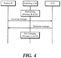
- FIG. 4 is a flowchart of a primary takeover procedure for switching the control of the ALD by primary B to the control of the ALD by primary A with primary B electrically connected to the ALD.
- the initiating message may include a procedure code (CMD) for indicating that the message is in accordance with the vendor specific procedure, a vendor code for identifying the vendor, and a procedure identifier for indicating that the initiating message is about changing the electrical connection to the ALD to that with another primary.
- CMD procedure code
- the initiating message may further include information on a port to which another primary (i.e., primary A) is connected before it makes a subsequent electrical connection with the ALD.
- the ALD Upon receiving the initiating message from primary B, the ALD sends a response message to the initiating message to primary B via the switching unit.
- Table 2 illustrates the response message for initiating the primary takeover procedure based on the vendor specific procedure prescribed by the 3GPP standard (for example, 3GPP TS 25.466).
- 3GPP TS 25.466 3GPP TS 25.466.
- CMD Vendor specific data 0x90 0x4B [K], 0x4D [M], 0x00 [Response OK], 0xA0 [Procedure Identifier]
- the response message may include a procedure code for indicating that the message is in accordance with the vendor specific procedure, a vendor code for identifying the vendor, a response code (response OK) for indicating a successful reception of the initiating message, and a procedure identifier for indicating that the response message is about the primary takeover.
- the switching unit relays the response message sent from the ALD to primary B, and then change the port to another one to which primary A is connected.
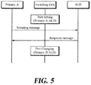
- FIG. 5 is a flowchart of a primary takeover procedure for switching the control of the ALD by primary A to the control of the ALD by primary B with primary A electrically connected to the ALD. Specific procedures correspond to those of FIG 4 , and the initiating message transmitted by primary A and the response message of ALD are illustrated respectively in the following Tables 3 and 4.
- the initiating message transmitted by primary A may contain information on a port for switching to primary B.
- a plurality of primaries can share one or more antennas, and in particular, various control management schemes can be provided for enabling two or more operators to operate any particular operator's ALD.
- an operator can reduce the time and costs associated with resetting of the antenna control system in the field in that the operator can select a particular primary to communicate with the ALD based on the vendor specific procedure acceptable to the AISG 2.0 standard.
Landscapes
- Engineering & Computer Science (AREA)
- Computer Networks & Wireless Communication (AREA)
- Signal Processing (AREA)
- Databases & Information Systems (AREA)
- Mobile Radio Communication Systems (AREA)
- Variable-Direction Aerials And Aerial Arrays (AREA)
Description
- The present disclosure in some embodiments relates to an antenna control system for base stations and its operation method. More particularly, the present disclosure in some embodiments relates to an antenna control system wherein multiple primaries perform selective communications with antenna line devices (ALDs) and to its operation method.
- The statements in this section merely provide background information related to the present disclosure and do not necessarily constitute prior art.
- Mobile radio antenna is installed with more and more functions that can be remotely queried or remotely controlled. Known applications of this kind include, for example, a remote electrical tilt (RET) device for electronic down tilt angle adjustment, a remote azimuth steering (RAB) device, a remote azimuth beamwidth (RAB), and the like.
- Such units could not be interconnected because each antenna manufacturer has a proprietary control system for its antenna, but recent LTE (Long Term Evolution) wireless or radio base stations, etc. are frequently adopting AISG (Antenna Interface Standards Group) or 3GPP (3rd Generation Partnership Project) standards for controlling antennas. The AISG standard is the specifications standardized for ensuring the interoperability of the antennas with respect to their tilting control schemes.
- Usually, a wireless base station antenna and its controlling RET device or such AISG device (AISG functional unit: Antenna Line Device or ALD) are placed in a high position, such as the top of a tower and a building roof. On the other hand, a wireless device for supplying power to the antenna or a control device (AISG control device: primary) can commonly be disposed at a lower position such as the bottom of the tower. Here, the control device transmits a control signal (RS485 standard signal) to an AISG device, and executes the control of the antenna by controlling the AISG device while supplying power to the AISG device.
- According to the 3GPP or AISG standards, RET control is largely classified by, for example, a primary station and the secondary station. A mobile communication base station may be typically configured by an antenna system installed at a high position of a building, pole, etc., a base station main system installed on the ground, and a feeder cable connecting between the two, wherein the primary station may correspond to the base station main system, and the secondary station to the antenna system.
- In such antenna systems, the antenna control apparatus has its wireless device output an RF signal which is a feed signal for supplying power to the antenna, has its AISG control device output an AISG signal composed of a direct current power for driving AISG units and their control signal. Then, a BS (base station) modem combines a modulated signal obtained by modulating the RF signal and AISG signal, and transmits the combined signal via the feeder cable to an antenna modem of the antenna system. The antenna system causes the antenna modem to separate the combined signal into the modulated signal and the RF signal, supply the antenna with the RF signal power after the separation, and provide the AISG devices with an output of the AISG signal composed of a direct current power and a control signal obtained from demodulating the modulated signal by a modem circuit (demodulation circuit) within the antenna modem.
-
GB 2 518 204 A -
US 2014/022124 A1 discloses a multi-beam shape supplementary device comprising a site sharing adapter in the form of a primary adapter having at least two primary connections for connecting at least two primary control units, the plug and/or connection configuration or connection assignment at the primary connections are connection-compatible with the connections on the coupling connection side of the site sharing adapter. -
EP 2 897 224 A1 - Embodiments of the present disclosure provide an antenna control system for controlling an antenna of a radio base station based on a 3GPP or AISG (Antenna Interface Standards Group) protocol, including at least one functional unit configured to control the antenna of the radio base station, a plurality of control devices configured to transmit a control signal to the functional unit so as to control and power the functional unit, and a switching unit configured to be interconnected between the plurality of control devices and the at least one functional unit so as to selectively electrically connect any of the plurality of control devices to the functional unit. The antenna control system may further include a feeder cable configured to connect the plurality of control devices with the switching unit, to connect the switching unit with the functional unit, and to have control signal lines for transmitting the control signal and a power supply line for powering the functional unit.
- Upon determining that a vendor specific procedure initiated by the control device in an electrical connection with the functional unit (hereinafter abbreviated as a 'first control device') is completed, the switching unit is configured to take over the electrical connection with the functional unit to another control device. The vendor specific procedure is configured to be carried out between the first control device and the functional unit.
- The vendor specific procedure includes transmitting, performed by the first control device, an initiating message that contains information on a takeover to another control device, to the functional unit, and transmitting a response message of the functional unit in response to the initiating message, to the first control device.
- The initiating message includes a procedure code for indicating that the initiating message is in accordance with the vendor specific procedure, a vendor code for identifying a vendor, and a procedure identifier for indicating that the initiating message is about the takeover to another control device. In some embodiments, the switching unit is configured to select a control device to be electrically connected with the functional unit, based on the information on the port included in the initiating message.
- In some embodiments, the response message includes a procedure code for indicating that the response message is in accordance with the vendor specific procedure, a vendor code for identifying a vendor, a procedure identifier for indicating that the response message is about the takeover to said another control device, and a response code (response OK) for indicating a successful reception of the initiating message.
- In some embodiments, the switching unit is configured to be a type-free device-neutral unit with a communication pursuant to the AISG standard. For example, the control unit may be configured to bypass the switching unit, and perform a direct communication with the function unit by the 3GPP or AISG protocol.
- In some embodiments, the switching unit may be configured to be implemented as a functional module in the functional unit.
- The functional unit may include at least any one of a remote radio unit (RRU), an antenna integrated radio (AIR), a tower mounted amplifier (TMA) and a remote electrical tilting (RET) device, an alignment sensor device (ASD), a clock source (ACS), a geographic location sensor (GLS), a configurable power monitor (CPM), a temperature sensor (ATS), a remote azimuth beamwidth (RAB), a remote azimuth steering (RAS) and an eAntenna (RAE) device.
- Another aspect of the present disclosure provides a switching unit interconnected between at least one functional unit for controlling an antenna of a radio base station and a plurality of control devices for transmitting a control signal to the functional unit so as to control and power the functional unit. Here, the switching unit includes at least one common terminal to which the functional unit is wired, a plurality of branch terminals to which the plurality of control devices is wired, a switch configured to selectively connect the common terminal to the plurality of branch terminals, a communication interface configured to support an AISG or 3GPP protocol connected to a side of the common terminal of the switch, and a control unit configured to be connected to the communication interface and to the switch, and to control the switch so as to selectively connect the common terminal to the plurality of branch terminals.
- Yet another aspect of the present disclosure provides a method for operating a switching unit which is interconnected between at least one functional unit for controlling an antenna of a radio base station and a plurality of control devices for transmitting a control signal to the functional unit so as to control and power the functional unit, and is configured to selectively electrically connect any of the plurality of control devices to the functional unit. Here, the method includes monitoring control signals between the functional unit and the control device in an electrical connection with the functional unit, and upon determining that a vendor specific procedure initiated by the control device in an electrical connection with the functional unit is completed, taking over the electrical connection with the functional unit to another control device.
-
-
FIGs. 1A and1B are schematic diagrams of antenna control systems according to some embodiments of the present disclosure. -
FIG. 2 is a schematic diagram of an antenna control system according to another embodiment of the present disclosure. -
FIG. 3 is a schematic diagram of a configuration of a switching unit according to some embodiments of the present disclosure. -
FIG. 4 andFIG. 5 are flowcharts of methods for operating an antenna control system according to some embodiments of the present disclosure. - Exemplary embodiments of the present disclosure are described below with reference to the accompanying drawings. In the following description, like reference numerals designate like elements, although the elements are shown in different drawings. Further, in the following description of the at least one embodiment, a detailed description of known functions and configurations incorporated herein will be omitted for the purpose of clarity and for brevity.
- Various terms such as first, second, A, B, (i), (ii), (a), (b), etc., are used solely for the purpose of differentiating one component from the other, but not to imply or suggest the substances, the order or sequence of the components. Throughout this specification, when a part "includes" or "comprises" a component, the part is meant to further include other components, not excluding thereof unless there is a particular description contrary thereto. The terms such as "unit", "module", and the like refer to units for processing at least one function or operation, which may be implemented by hardware, software, or a combination thereof. Throughout the specification, the Antenna Interface Standards Group (AISG) standard and the 3rd Generation Partnership Project (3GPP) standard (TS 25.460 to TS 25.466) are incorporated by reference. The above AISG standard is completely included in the 3GPP standard in its entirety, and functions defined in the 3GPP standard are similar to the AISG 2.0.
- Some embodiments of the present disclosure seek to provide an antenna control system with multiple primaries performing selective communication with an ALD and a method for operating the antenna control system.
- In the antenna control system according to some embodiments of the present disclosure, multiple control devices (i.e., primaries) share an antenna of the same base station and one or more functional units (i.e., Antenna Line Devices: ALDs) for executing the antenna control. Any one of the multiple primaries is under the control of a switching unit located between the multiple primaries and the ALDs, for exclusively controlling the ALDs. In particular, the antenna control system controls the antenna of the radio base station pursuant to the UTRAN Iuant interface of 3GPP TS or a communication protocol defined by AISG.
-
FIGs. 1A and1B are schematic diagrams of antenna control systems according to some embodiments of the present disclosure. - Referring to
FIG. 1A , the antenna control system includes an ALD 100 including a plurality of functional units for executing control of an antenna of a radio base station, aswitching unit 200, and a plurality ofprimaries ALD 100 and thereby controlling as well as powering thereof, wherein theswitching unit 200 is interposed between the plurality ofprimaries multiple primaries switching unit 200 are interconnected via a feeder cable having control signal lines for transmitting the control signal and a power supply line for the power supplying. Further, there may be a plurality ofALDs 100 included in the antenna control system, when they may be structured by daisy chain connections. The antenna control system may include any of a variety of ALDs such as a remote radio unit (RRU), antenna integrated radio (AIR), tower mounted amplifier (TMA) and remote electrical tilting (RET) device, alignment sensor device (ASD), clock source (ACS), geographic location sensor (GLS), configurable power monitor (CPM), temperature sensor (ATS), remote azimuth beamwidth (RAB), remote azimuth steering (RAS) and eAntenna (RAE) among others. - The
switching unit 100 selectively and electrically connects any one of the plurality ofprimaries ALD 100. The switching operation for the selective connection to theALD 100 is triggered by a primary takeover protocol that is initiated by the connected primary 300a or 300b. For example, theswitching unit 200 monitors the control signals between the primaries and their interconnected ALD, and upon determining the completion of a primary takeover procedure in accordance with a certain protocol that is initiated by the connected primary, theswitching unit 200 disconnects the connected primary from the functional unit and establishes a connection to theALD 100 associated with anotherPrimary 100. - Here, the
switching unit 200 is a type-free device-neutral unit with a communication protocol pursuant to the AISG or 3GPP standard. Therefore, theprimaries switching unit 200, they perform direct communications with theALD 100 in accordance with the above protocol. Similarly, theALD 100 is treated as having no switchingunit 200, and it communicates directly with theprimaries - The
primaries switching unit 200 to carry out direct communications with theALD 100 in accordance with a communication protocol of the above 3GPP or the AISG standard. This facilitates to perform communications pursuant to the above standards or the power supplying more stably. -
FIG. 1A illustrates the antenna control system having asingle ALD 100 and twoprimaries FIG. 1B includes a plurality of ALDs 100-1, 100-2, ... 100-n for executing control of a plurality of antennas, aswitching unit 200, and a plurality of primaries 300-1, 300-2, ... 300-m for transmitting a control signal selectively to one of the plurality of ALDs 100-1, 100-2, ... 100-n and thereby controlling as well as powering thereof, wherein theswitching unit 200 is interposed between the plurality of primaries 300-1, 300-2, ... 300-m and the plurality of ALDs 100-1, 100-2, ... 100-n. - On the other hand,
FIGs. 1A and1B illustrate theswitching unit 200 as a separate object independent of the ALD, although theswitching unit 200 may be implemented in some other embodiments as one functional module in the ALD so that it operates in accordance with control signals of at least one CPU provided to the ALD. -
FIG. 2 is a schematic diagram of an antenna control system according to another embodiment of the present disclosure. - In the antenna control system according to some embodiments, multiple primaries 300-1, 300-2 share at least two antennas and at least two ALDs 100-1, 100-2 for controlling the antennas. Under the control of switching units 200-1, 200-2 located between the multiple primaries 300-1, 300-2 and the ALDs 100-1, 100-2, one of the multiple primaries 300-1, 300-2 exclusively controls the ALDs 100-1, 100-2. To this end, a splitter 400-1 is interposed between the primary 300-1 and the switching unit 200-1, and a splitter 400-2 is interposed between the primary 300-2 and the switching unit 200-2. The splitters 400-1 and 400-2 respectively bifurcate the feeder cables connected with the primaries 300-1, 300-2 to connect the furcated feeder cables to the switching units 200-1, 200-2 leading to the respective ALDs 100-1, 100-2. Here, the splitters 400-1 and 400-2 are free of a device type with a communication protocol pursuant to the AISG or 3GPP standard as are the switching units 200-1, 200-2.
FIG. 2 illustrates a pair of the ALDs 100-1, 100-2, a pair of the switching units 200-1, 200-2, a pair of the splitters 400-1, 400-2 and a pair of primaries 300-1, 300-2 for the purpose of simplicity, although the respective units may be variously combined and/or the switching unit and the splitter may have terminals of different numbers from those illustrated. -
FIG. 3 is a schematic diagram of a configuration of aswitching unit 200 according to some embodiments of the present disclosure. - The
switching unit 200 includes acommon terminal 31 to which theALD 100 is connected via a AISG cable, andseparate branch terminals FIG. 3 illustrates twobranch terminals switching unit 200 in some embodiments. Theswitching unit 200 further includes aswitch 32 for connecting thecommon terminal 31 selectively to themultiple branch terminals communication interface 33 that supports the AISG or 3GPP protocol which is connected to the side of thecommon terminal 31 of theswitch 32, and acontrol unit 34 connected to thecommunication interface 33 and to theswitch 32. Theswitch 32 may have a plurality of ports for selectively connecting thecommon terminal 31 to the plurality ofbranch terminals - To selectively connect the
common terminal 31 to the plurality ofbranch terminals control unit 34 controls theswitch 32. Taking over by theswitch 32 is triggered by a primary takeover procedure initiated by the primaries connected to thebranch terminal common terminal 31. A particular protocol as mentioned above may be configured based on the vendor specific procedure as defined by the 3GPP standard. For example, thecontrol unit 34 monitors, via thecommunication interface 33, control signals between the interconnected common terminal 31 (or ALD of its connected antenna) and the branch terminal (or its connected primary). Upon confirming the completion of the predetermined vendor specific procedure initiated by the connected primary, thecontrol unit 34 controls theswitch 32 so as to disconnect the primary from its connected ALD and to establish a connection of another primary to that ALD. - Hereinafter, with reference to
FIGs. 4 and5 , a description will be provided on a primary takeover procedure of an antenna control system according to some embodiments of the present disclosure. -
FIG. 4 is a flowchart of a primary takeover procedure for switching the control of the ALD by primary B to the control of the ALD by primary A with primary B electrically connected to the ALD. - When primary B, which is electrically connected to the ALD, is to pass control of the ALD to primary A, it sends an initiating message to the ALD via a switching unit. Table 1 below illustrates the initiating message for starting the primary takeover procedure based on the vendor specific procedure prescribed by the 3GPP standard (for example, 3GPP TS 25.466).
[Table 1] CMD Vendor Code Vendor specific data 0x90 0x4B [K], 0x4D [M] 0xA0 [Procedure Identifier], 0x01 [Primary A Port Number] - As shown in Table 1, the initiating message may include a procedure code (CMD) for indicating that the message is in accordance with the vendor specific procedure, a vendor code for identifying the vendor, and a procedure identifier for indicating that the initiating message is about changing the electrical connection to the ALD to that with another primary. The initiating message may further include information on a port to which another primary (i.e., primary A) is connected before it makes a subsequent electrical connection with the ALD.
- Upon receiving the initiating message from primary B, the ALD sends a response message to the initiating message to primary B via the switching unit. Table 2 below illustrates the response message for initiating the primary takeover procedure based on the vendor specific procedure prescribed by the 3GPP standard (for example, 3GPP TS 25.466).
[Table 2] CMD Vendor specific data 0x90 0x4B [K], 0x4D [M], 0x00 [Response OK], 0xA0 [Procedure Identifier] - As shown in Table 2, the response message may include a procedure code for indicating that the message is in accordance with the vendor specific procedure, a vendor code for identifying the vendor, a response code (response OK) for indicating a successful reception of the initiating message, and a procedure identifier for indicating that the response message is about the primary takeover.
- The switching unit relays the response message sent from the ALD to primary B, and then change the port to another one to which primary A is connected.
-
FIG. 5 is a flowchart of a primary takeover procedure for switching the control of the ALD by primary A to the control of the ALD by primary B with primary A electrically connected to the ALD. Specific procedures correspond to those ofFIG 4 , and the initiating message transmitted by primary A and the response message of ALD are illustrated respectively in the following Tables 3 and 4.[Table 3] CMD Vendor Code Vendor specific data 0x90 0x4B [K], 0x4D [M] 0xA0 [Procedure Identifier], 0x02 [Primary B Port Number] [Table 4] CMD Vendor Code Vendor specific data 0x90 0x4B [K], 0x4D [M] 0xA0 [Procedure Identifier], 0x02 [Primary B Port Number] - As illustrated in Table 3, the initiating message transmitted by primary A may contain information on a port for switching to primary B.
- As explained above, according to some aspects of the present disclosure, a plurality of primaries can share one or more antennas, and in particular, various control management schemes can be provided for enabling two or more operators to operate any particular operator's ALD.
- Moreover, according to another aspect of the present disclosure, an operator can reduce the time and costs associated with resetting of the antenna control system in the field in that the operator can select a particular primary to communicate with the ALD based on the vendor specific procedure acceptable to the AISG 2.0 standard.
- Although exemplary embodiments of the present disclosure have been described for illustrative purposes, those skilled in the art will appreciate that various modifications, additions and substitutions are possible, without departing from the various characteristics of the disclosure. Therefore, exemplary embodiments of the present disclosure have been described for the sake of brevity and clarity. Accordingly, one of ordinary skill would understand the scope of the disclosure is not limited by the explicitly described above embodiments but by the appended claims.
| 00,100a, 100b, 100-1∼100-n: ALD (Antenna Line Device) | |
| 200, 200-1∼200-2: | |
| 300a, 300b, 300-1∼300-m: Primary | 400-1,400-2: Splitter |
| 31: Common terminal | 32: Switch |
| 33: Communication interface | 340: |
| 36a, 36b: | |
Claims (15)
- An antenna control system for controlling an antenna of a radio base station based on a 3GPP or AISG (Antenna Interface Standards Group) protocol, the antenna control system comprising:at least one functional unit (100,100a, 100b, 100-1∼100-n) configured to control the antenna of the radio base station;a plurality of control devices (300a, 300b, 300-1∼300-m) configured to transmit a control signal to the functional unit (100,100a, 100b, 100-1∼100-n) so as to control and power the functional unit; characterized in thata switching unit (200,200-1∼200-2) configured to be interconnected between the plurality of control devices (300a, 300b, 300-1∼300-m) and the at least one functional unit (100,100a, 100b, 100-1∼100-n) so as to selectively electrically connect any of the plurality of control devices (300a, 300b, 300-1∼300-m) to the functional unit, wherein, upon determining that a vendor specific procedure initiated by the control device (300a, 300b, 300-1∼300-m) in an electrical connection with the functional unit (100,100a, 100b, 100-1∼100-n) - hereinafter abbreviated as a 'first control device' - is completed, the switching unit (200,200-1∼200-2) is configured to take over the electrical connection with the functional unit (100,100a, 100b, 100-1∼100-n) to another control device, wherein the vendor specific procedure is configured to be carried out between the first control device (300a, 300b, 300-1∼300-m) and the functional unit,wherein the vendor specific procedure comprises:transmitting, performed by the first control device, an initiating message that contains information on a takeover to said another control device, to the functional unit; andtransmitting a response message of the functional unit (100,100a, 100b, 100-1∼100-n) in response to the initiating message, to the first control device.
- The antenna control system of claim 1, wherein the initiating message comprises:a procedure code for indicating that the initiating message is in accordance with the vendor specific procedure;a vendor code for identifying a vendor; anda procedure identifier for indicating that the initiating message is about the takeover to said another control device.
- The antenna control system of claim 2, wherein the initiating message further comprises an information on a port to which said another control device (300a, 300b, 300-1∼300-m) is connected.
- The antenna control system of claim 3, wherein the switching unit (200,200-1∼200-2) is configured to select a control device (300a, 300b, 300-1∼300-m) to be electrically connected with the functional unit, based on the information on the port included in the initiating message.
- The antenna control system of claim 1, wherein the response message comprises:a procedure code for indicating that the response message is in accordance with the vendor specific procedure;a vendor code for identifying a vendor;a procedure identifier for indicating that the response message is about the takeover to said another control device; anda response code (response OK) for indicating a successful reception of the initiating message.
- The antenna control system of claim 1, wherein the switching unit (200, 200-1∼200-2) is configured to be implemented as a functional module in the functional unit.
- The antenna control system of claim 1, wherein the control unit (340) is configured to
bypass the switching unit; and
perform a direct communication with the function unit by the 3GPP or AISG protocol. - The antenna control system of claim 1, wherein the functional unit (100,100a, 100b, 100-1∼100-n) comprises at least any one of a remote radio unit (RRU), an antenna integrated radio (AIR), a tower mounted amplifier (TMA) and a remote electrical tilting (RET) device, an alignment sensor device (ASD), a clock source (ACS), a geographic location sensor (GLS), a configurable power monitor (CPM), a temperature sensor (ATS), a remote azimuth beamwidth (RAB), a remote azimuth steering (RAS) and an eAntenna (RAE) device.
- A switching unit interconnected between at least one functional unit (100,100a, 100b, 100-1∼100-n) for controlling an antenna of a radio base station and a plurality of control devices (300a, 300b, 300-1∼300-m) for transmitting a control signal to the functional unit (100,100a, 100b, 100-1∼100-n) so as to control and power the functional unit, the switching unit (200,200-1∼200-2) comprising:at least one common terminal to which the functional unit (100,100a, 100b, 100-1∼100-n) is wired;a plurality of branch terminals (36a, 36b) to which the plurality of control devices (300a, 300b, 300-1∼300-m) is wired;a switch (32) configured to selectively connect the common terminal to the plurality of branch terminals;a communication interface (33) configured to support an AISG or 3GPP protocol connected to a side of the common terminal of the switch; anda control unit (340) configured to be connected to the communication interface (33) and to the switch, and to control the switch (32) so as to selectively connect the common terminal to the plurality of branch terminals, wherein the control unit (340) is configured tomonitor control signals between the functional unit (100,100a, 100b, 100-1∼100-n) and the control device (300a, 300b, 300-1∼300-m) in an electrical connection with the functional unit; andupon determining that a vendor specific procedure initiated by the control device (300a, 300b, 300-1∼300-m) in the electrical connection with the functional unit, control the switch (32) to take over the electrical connection with the functional unit (100,100a, 100b, 100-1∼100-n) to another control device (300a, 300b, 300-1∼300-m) characterized in that the vendor specific procedure comprises:transmitting, performed by the control device (300a, 300b, 300-1∼300-m) in the electrical connection with the functional unit, an initiating message that contains information on a takeover to said another control device, to the functional unit; andtransmitting a response message of the functional unit (100,100a, 100b, 100-1∼100-n) in response to the initiating message, to the control device (300a, 300b, 300-1∼300-m) in the electrical connection with the functional unit.
- The switching unit of claim 9, wherein the vendor specific procedure is configured to be carried out between the functional unit (100,100a, 100b, 100-1∼100-n) and the control device (300a, 300b, 300-1∼300-m) in the electrical connection with the functional unit.
- The switching unit of claim 9, wherein the initiating message comprises:a procedure code for indicating that the initiating message is in accordance with the vendor specific procedure;a vendor code for identifying a vendor; anda procedure identifier for indicating that the initiating message is about the takeover to said another control device.
- The switching unit of claim 11, wherein the initiating message further comprises an information on a port to which said another control device (300a, 300b, 300-1∼300-m) is connected.
- The switching unit of claim 9, wherein the switching unit (200,200-1∼200-2) is configured to be a type-free device-neutral unit with a communication pursuant to the AISG or 3GPP protocol.
- The switching unit of claim 9, wherein the switching unit (200,200-1∼200-2) is configured to be implemented as a functional module in the functional unit.
- A method for operating a switching unit (200,200-1∼200-2) which is interconnected between at least one functional unit (100,100a, 100b, 100-1∼100-n) for controlling an antenna of a radio base station and a plurality of control devices (300a, 300b, 300-1∼300-m) for transmitting a control signal to the functional unit (100,100a, 100b, 100-1∼100-n) so as to control and power the functional unit, and is configured to selectively electrically connect any of the plurality of control devices (300a, 300b, 300-1∼300-m) to the functional unit, the method comprising:
monitoring control signals between the functional unit (100,100a, 100b, 100-1∼100-n) and the control device (300a, 300b, 300-1∼300-m) in an electrical connection with the functional unit; characterized in that
upon determining that a vendor specific procedure initiated by the control device (300a, 300b, 300-1∼300-m) in an electrical connection with the functional unit (100,100a, 100b, 100-1∼100-n) (hereinafter abbreviated as a 'first control device') is completed, taking over the electrical connection with the functional unit (100,100a, 100b, 100-1∼100-n) to another control device, where the vendor specific procedure comprises:
transmitting, performed by the control device (300a, 300b, 300-1∼300-m) in the electrical connection with the functional unit, an initiating message that contains information on a takeover to said another control device, to the functional unit; and
transmitting a response message of the functional unit (100,100a, 100b, 100-1∼100-n) in response to the initiating message, to the control device (300a, 300b, 300-1∼300-m) in the electrical connection with the functional unit.
Applications Claiming Priority (1)
| Application Number | Priority Date | Filing Date | Title |
|---|---|---|---|
| KR1020150056165A KR102345228B1 (en) | 2015-04-21 | 2015-04-21 | Antenna Control System and its Operating Method |
Publications (2)
| Publication Number | Publication Date |
|---|---|
| EP3086620A1 EP3086620A1 (en) | 2016-10-26 |
| EP3086620B1 true EP3086620B1 (en) | 2019-07-24 |
Family
ID=55802229
Family Applications (1)
| Application Number | Title | Priority Date | Filing Date |
|---|---|---|---|
| EP16165629.3A Active EP3086620B1 (en) | 2015-04-21 | 2016-04-15 | Antenna control system and its operating method |
Country Status (3)
| Country | Link |
|---|---|
| US (1) | US9913129B2 (en) |
| EP (1) | EP3086620B1 (en) |
| KR (1) | KR102345228B1 (en) |
Families Citing this family (6)
| Publication number | Priority date | Publication date | Assignee | Title |
|---|---|---|---|---|
| KR101824220B1 (en) * | 2016-05-12 | 2018-01-31 | 주식회사 케이엠더블유 | Apparatus for guiding antenna alignment |
| KR101816549B1 (en) | 2016-09-29 | 2018-01-10 | 엘지디스플레이 주식회사 | Touch display apparatus |
| CN106658406A (en) * | 2016-11-18 | 2017-05-10 | 京信通信技术(广州)有限公司 | Positioning method and device |
| CN108199726B (en) * | 2018-03-16 | 2020-08-28 | Oppo广东移动通信有限公司 | Multi-way selector switch and related products |
| CN109600176A (en) * | 2018-12-29 | 2019-04-09 | 京信通信技术(广州)有限公司 | Signal shunt circuit and calibration network |
| CN111856160B (en) * | 2020-07-30 | 2022-11-22 | 苏州韦博通信技术有限公司 | Test system of electric tilt antenna equipment |
Family Cites Families (8)
| Publication number | Priority date | Publication date | Assignee | Title |
|---|---|---|---|---|
| US7177667B2 (en) * | 2003-11-25 | 2007-02-13 | Kmw Inc. | Antenna remote control apparatus of mobile communication base station system |
| CN1983857A (en) * | 2006-04-05 | 2007-06-20 | 华为技术有限公司 | Method and device for configuring parameter of antenna equipment |
| DE102011015551B4 (en) * | 2011-03-30 | 2012-12-20 | Kathrein-Werke Kg | Multi-beam shape-accessory |
| KR101945405B1 (en) * | 2012-01-27 | 2019-02-08 | 주식회사 케이엠더블유 | Antenna system of mobile communication base transceiver station |
| WO2014042444A1 (en) * | 2012-09-14 | 2014-03-20 | 주식회사 케이엠더블유 | Antenna of mobile communication base station and method for controlling same |
| GB2518204B (en) * | 2013-09-13 | 2017-09-06 | Kathrein Werke Kg | Antenna System |
| US9660328B2 (en) * | 2014-06-30 | 2017-05-23 | John Mezzalingua Associates, LLC | Mounting assembly for an integrated remote radio head and antenna system |
| US9967003B2 (en) * | 2014-11-06 | 2018-05-08 | Commscope Technologies Llc | Distributed antenna system with dynamic capacity allocation and power adjustment |
-
2015
- 2015-04-21 KR KR1020150056165A patent/KR102345228B1/en active IP Right Grant
-
2016
- 2016-04-15 EP EP16165629.3A patent/EP3086620B1/en active Active
- 2016-04-20 US US15/133,888 patent/US9913129B2/en active Active
Non-Patent Citations (1)
| Title |
|---|
| None * |
Also Published As
| Publication number | Publication date |
|---|---|
| KR20160125600A (en) | 2016-11-01 |
| US20160316359A1 (en) | 2016-10-27 |
| EP3086620A1 (en) | 2016-10-26 |
| US9913129B2 (en) | 2018-03-06 |
| KR102345228B1 (en) | 2021-12-31 |
Similar Documents
| Publication | Publication Date | Title |
|---|---|---|
| EP3086620B1 (en) | Antenna control system and its operating method | |
| CN110677835B (en) | Dual-network converged train control wireless communication system and method | |
| KR101540224B1 (en) | Antenna system comprising antenna transmission control device | |
| EP2897224B1 (en) | Antenna of mobile communication base station and method for controlling same | |
| US10050341B2 (en) | Apparatus for controlling antenna of mobile-communication base station | |
| US9148338B2 (en) | Base station and method for remote management in a cellular communication network | |
| US20150140986A1 (en) | Auxiliary Channel Remote Device Management, Diagnostics, and Self-Installation | |
| JP4909417B2 (en) | Apparatus and method for controlling an antenna system in a communication system | |
| ES2756825T3 (en) | Matching method and device | |
| US20110188413A1 (en) | Wireless repeater device, method and system for implementing control of the same in a wireless network system | |
| US10321337B2 (en) | Antenna control system in base station system and configuration method therefor | |
| US9775090B2 (en) | Method and equipment for controlling mobile station to switch between different wireless communication systems | |
| US20160233917A1 (en) | Device for forming wireless high-frequency signal path and method for controlling same | |
| KR20130130281A (en) | Antenna phase shifting device and antenna phase shifting system using the same | |
| CN108987894B (en) | Antenna control method and antenna device | |
| EP1995879B1 (en) | Base station and transmission method | |
| CN103516408A (en) | Antenna feeder network system | |
| WO2016008164A1 (en) | Signal transmission method, interface extension apparatus and communication system | |
| KR101535811B1 (en) | Antena interface device for mobile communication radioaccess system | |
| US10165623B2 (en) | Splitter device connecting multiple remote radio heads | |
| CN100389620C (en) | Method and system for making transmitting-receiving machine moudel obtain self-position information | |
| WO2019074462A2 (en) | Internet of things (iot) module of multiple channels |
Legal Events
| Date | Code | Title | Description |
|---|---|---|---|
| PUAI | Public reference made under article 153(3) epc to a published international application that has entered the european phase |
Free format text: ORIGINAL CODE: 0009012 |
|
| AK | Designated contracting states |
Kind code of ref document: A1 Designated state(s): AL AT BE BG CH CY CZ DE DK EE ES FI FR GB GR HR HU IE IS IT LI LT LU LV MC MK MT NL NO PL PT RO RS SE SI SK SM TR |
|
| AX | Request for extension of the european patent |
Extension state: BA ME |
|
| STAA | Information on the status of an ep patent application or granted ep patent |
Free format text: STATUS: REQUEST FOR EXAMINATION WAS MADE |
|
| 17P | Request for examination filed |
Effective date: 20170424 |
|
| RBV | Designated contracting states (corrected) |
Designated state(s): AL AT BE BG CH CY CZ DE DK EE ES FI FR GB GR HR HU IE IS IT LI LT LU LV MC MK MT NL NO PL PT RO RS SE SI SK SM TR |
|
| GRAP | Despatch of communication of intention to grant a patent |
Free format text: ORIGINAL CODE: EPIDOSNIGR1 |
|
| STAA | Information on the status of an ep patent application or granted ep patent |
Free format text: STATUS: GRANT OF PATENT IS INTENDED |
|
| INTG | Intention to grant announced |
Effective date: 20190205 |
|
| RAP1 | Party data changed (applicant data changed or rights of an application transferred) |
Owner name: KMW INC. |
|
| GRAS | Grant fee paid |
Free format text: ORIGINAL CODE: EPIDOSNIGR3 |
|
| GRAA | (expected) grant |
Free format text: ORIGINAL CODE: 0009210 |
|
| STAA | Information on the status of an ep patent application or granted ep patent |
Free format text: STATUS: THE PATENT HAS BEEN GRANTED |
|
| AK | Designated contracting states |
Kind code of ref document: B1 Designated state(s): AL AT BE BG CH CY CZ DE DK EE ES FI FR GB GR HR HU IE IS IT LI LT LU LV MC MK MT NL NO PL PT RO RS SE SI SK SM TR |
|
| REG | Reference to a national code |
Ref country code: GB Ref legal event code: FG4D |
|
| REG | Reference to a national code |
Ref country code: CH Ref legal event code: EP |
|
| REG | Reference to a national code |
Ref country code: DE Ref legal event code: R096 Ref document number: 602016017186 Country of ref document: DE |
|
| REG | Reference to a national code |
Ref country code: AT Ref legal event code: REF Ref document number: 1159867 Country of ref document: AT Kind code of ref document: T Effective date: 20190815 |
|
| REG | Reference to a national code |
Ref country code: IE Ref legal event code: FG4D |
|
| REG | Reference to a national code |
Ref country code: SE Ref legal event code: TRGR |
|
| REG | Reference to a national code |
Ref country code: NL Ref legal event code: MP Effective date: 20190724 |
|
| REG | Reference to a national code |
Ref country code: LT Ref legal event code: MG4D |
|
| REG | Reference to a national code |
Ref country code: AT Ref legal event code: MK05 Ref document number: 1159867 Country of ref document: AT Kind code of ref document: T Effective date: 20190724 |
|
| PG25 | Lapsed in a contracting state [announced via postgrant information from national office to epo] |
Ref country code: FI Free format text: LAPSE BECAUSE OF FAILURE TO SUBMIT A TRANSLATION OF THE DESCRIPTION OR TO PAY THE FEE WITHIN THE PRESCRIBED TIME-LIMIT Effective date: 20190724 Ref country code: NL Free format text: LAPSE BECAUSE OF FAILURE TO SUBMIT A TRANSLATION OF THE DESCRIPTION OR TO PAY THE FEE WITHIN THE PRESCRIBED TIME-LIMIT Effective date: 20190724 Ref country code: AT Free format text: LAPSE BECAUSE OF FAILURE TO SUBMIT A TRANSLATION OF THE DESCRIPTION OR TO PAY THE FEE WITHIN THE PRESCRIBED TIME-LIMIT Effective date: 20190724 Ref country code: PT Free format text: LAPSE BECAUSE OF FAILURE TO SUBMIT A TRANSLATION OF THE DESCRIPTION OR TO PAY THE FEE WITHIN THE PRESCRIBED TIME-LIMIT Effective date: 20191125 Ref country code: BG Free format text: LAPSE BECAUSE OF FAILURE TO SUBMIT A TRANSLATION OF THE DESCRIPTION OR TO PAY THE FEE WITHIN THE PRESCRIBED TIME-LIMIT Effective date: 20191024 Ref country code: HR Free format text: LAPSE BECAUSE OF FAILURE TO SUBMIT A TRANSLATION OF THE DESCRIPTION OR TO PAY THE FEE WITHIN THE PRESCRIBED TIME-LIMIT Effective date: 20190724 Ref country code: LT Free format text: LAPSE BECAUSE OF FAILURE TO SUBMIT A TRANSLATION OF THE DESCRIPTION OR TO PAY THE FEE WITHIN THE PRESCRIBED TIME-LIMIT Effective date: 20190724 Ref country code: NO Free format text: LAPSE BECAUSE OF FAILURE TO SUBMIT A TRANSLATION OF THE DESCRIPTION OR TO PAY THE FEE WITHIN THE PRESCRIBED TIME-LIMIT Effective date: 20191024 |
|
| PG25 | Lapsed in a contracting state [announced via postgrant information from national office to epo] |
Ref country code: ES Free format text: LAPSE BECAUSE OF FAILURE TO SUBMIT A TRANSLATION OF THE DESCRIPTION OR TO PAY THE FEE WITHIN THE PRESCRIBED TIME-LIMIT Effective date: 20190724 Ref country code: LV Free format text: LAPSE BECAUSE OF FAILURE TO SUBMIT A TRANSLATION OF THE DESCRIPTION OR TO PAY THE FEE WITHIN THE PRESCRIBED TIME-LIMIT Effective date: 20190724 Ref country code: AL Free format text: LAPSE BECAUSE OF FAILURE TO SUBMIT A TRANSLATION OF THE DESCRIPTION OR TO PAY THE FEE WITHIN THE PRESCRIBED TIME-LIMIT Effective date: 20190724 Ref country code: GR Free format text: LAPSE BECAUSE OF FAILURE TO SUBMIT A TRANSLATION OF THE DESCRIPTION OR TO PAY THE FEE WITHIN THE PRESCRIBED TIME-LIMIT Effective date: 20191025 Ref country code: IS Free format text: LAPSE BECAUSE OF FAILURE TO SUBMIT A TRANSLATION OF THE DESCRIPTION OR TO PAY THE FEE WITHIN THE PRESCRIBED TIME-LIMIT Effective date: 20191124 Ref country code: RS Free format text: LAPSE BECAUSE OF FAILURE TO SUBMIT A TRANSLATION OF THE DESCRIPTION OR TO PAY THE FEE WITHIN THE PRESCRIBED TIME-LIMIT Effective date: 20190724 |
|
| PG25 | Lapsed in a contracting state [announced via postgrant information from national office to epo] |
Ref country code: TR Free format text: LAPSE BECAUSE OF FAILURE TO SUBMIT A TRANSLATION OF THE DESCRIPTION OR TO PAY THE FEE WITHIN THE PRESCRIBED TIME-LIMIT Effective date: 20190724 |
|
| PG25 | Lapsed in a contracting state [announced via postgrant information from national office to epo] |
Ref country code: IT Free format text: LAPSE BECAUSE OF FAILURE TO SUBMIT A TRANSLATION OF THE DESCRIPTION OR TO PAY THE FEE WITHIN THE PRESCRIBED TIME-LIMIT Effective date: 20190724 Ref country code: EE Free format text: LAPSE BECAUSE OF FAILURE TO SUBMIT A TRANSLATION OF THE DESCRIPTION OR TO PAY THE FEE WITHIN THE PRESCRIBED TIME-LIMIT Effective date: 20190724 Ref country code: PL Free format text: LAPSE BECAUSE OF FAILURE TO SUBMIT A TRANSLATION OF THE DESCRIPTION OR TO PAY THE FEE WITHIN THE PRESCRIBED TIME-LIMIT Effective date: 20190724 Ref country code: DK Free format text: LAPSE BECAUSE OF FAILURE TO SUBMIT A TRANSLATION OF THE DESCRIPTION OR TO PAY THE FEE WITHIN THE PRESCRIBED TIME-LIMIT Effective date: 20190724 |
|
| PG25 | Lapsed in a contracting state [announced via postgrant information from national office to epo] |
Ref country code: CZ Free format text: LAPSE BECAUSE OF FAILURE TO SUBMIT A TRANSLATION OF THE DESCRIPTION OR TO PAY THE FEE WITHIN THE PRESCRIBED TIME-LIMIT Effective date: 20190724 Ref country code: SK Free format text: LAPSE BECAUSE OF FAILURE TO SUBMIT A TRANSLATION OF THE DESCRIPTION OR TO PAY THE FEE WITHIN THE PRESCRIBED TIME-LIMIT Effective date: 20190724 Ref country code: SM Free format text: LAPSE BECAUSE OF FAILURE TO SUBMIT A TRANSLATION OF THE DESCRIPTION OR TO PAY THE FEE WITHIN THE PRESCRIBED TIME-LIMIT Effective date: 20190724 Ref country code: IS Free format text: LAPSE BECAUSE OF FAILURE TO SUBMIT A TRANSLATION OF THE DESCRIPTION OR TO PAY THE FEE WITHIN THE PRESCRIBED TIME-LIMIT Effective date: 20200224 |
|
| REG | Reference to a national code |
Ref country code: DE Ref legal event code: R097 Ref document number: 602016017186 Country of ref document: DE |
|
| PLBE | No opposition filed within time limit |
Free format text: ORIGINAL CODE: 0009261 |
|
| STAA | Information on the status of an ep patent application or granted ep patent |
Free format text: STATUS: NO OPPOSITION FILED WITHIN TIME LIMIT |
|
| PG2D | Information on lapse in contracting state deleted |
Ref country code: IS |
|
| 26N | No opposition filed |
Effective date: 20200603 |
|
| PG25 | Lapsed in a contracting state [announced via postgrant information from national office to epo] |
Ref country code: SI Free format text: LAPSE BECAUSE OF FAILURE TO SUBMIT A TRANSLATION OF THE DESCRIPTION OR TO PAY THE FEE WITHIN THE PRESCRIBED TIME-LIMIT Effective date: 20190724 |
|
| REG | Reference to a national code |
Ref country code: DE Ref legal event code: R119 Ref document number: 602016017186 Country of ref document: DE |
|
| PG25 | Lapsed in a contracting state [announced via postgrant information from national office to epo] |
Ref country code: MC Free format text: LAPSE BECAUSE OF FAILURE TO SUBMIT A TRANSLATION OF THE DESCRIPTION OR TO PAY THE FEE WITHIN THE PRESCRIBED TIME-LIMIT Effective date: 20190724 |
|
| REG | Reference to a national code |
Ref country code: CH Ref legal event code: PL |
|
| PG25 | Lapsed in a contracting state [announced via postgrant information from national office to epo] |
Ref country code: LI Free format text: LAPSE BECAUSE OF NON-PAYMENT OF DUE FEES Effective date: 20200430 Ref country code: DE Free format text: LAPSE BECAUSE OF NON-PAYMENT OF DUE FEES Effective date: 20201103 Ref country code: FR Free format text: LAPSE BECAUSE OF NON-PAYMENT OF DUE FEES Effective date: 20200430 Ref country code: CH Free format text: LAPSE BECAUSE OF NON-PAYMENT OF DUE FEES Effective date: 20200430 Ref country code: LU Free format text: LAPSE BECAUSE OF NON-PAYMENT OF DUE FEES Effective date: 20200415 |
|
| REG | Reference to a national code |
Ref country code: BE Ref legal event code: MM Effective date: 20200430 |
|
| PG25 | Lapsed in a contracting state [announced via postgrant information from national office to epo] |
Ref country code: BE Free format text: LAPSE BECAUSE OF NON-PAYMENT OF DUE FEES Effective date: 20200430 |
|
| GBPC | Gb: european patent ceased through non-payment of renewal fee |
Effective date: 20200415 |
|
| PG25 | Lapsed in a contracting state [announced via postgrant information from national office to epo] |
Ref country code: GB Free format text: LAPSE BECAUSE OF NON-PAYMENT OF DUE FEES Effective date: 20200415 Ref country code: IE Free format text: LAPSE BECAUSE OF NON-PAYMENT OF DUE FEES Effective date: 20200415 |
|
| PG25 | Lapsed in a contracting state [announced via postgrant information from national office to epo] |
Ref country code: MT Free format text: LAPSE BECAUSE OF FAILURE TO SUBMIT A TRANSLATION OF THE DESCRIPTION OR TO PAY THE FEE WITHIN THE PRESCRIBED TIME-LIMIT Effective date: 20190724 Ref country code: CY Free format text: LAPSE BECAUSE OF FAILURE TO SUBMIT A TRANSLATION OF THE DESCRIPTION OR TO PAY THE FEE WITHIN THE PRESCRIBED TIME-LIMIT Effective date: 20190724 |
|
| PG25 | Lapsed in a contracting state [announced via postgrant information from national office to epo] |
Ref country code: RO Free format text: LAPSE BECAUSE OF FAILURE TO SUBMIT A TRANSLATION OF THE DESCRIPTION OR TO PAY THE FEE WITHIN THE PRESCRIBED TIME-LIMIT Effective date: 20190724 Ref country code: MK Free format text: LAPSE BECAUSE OF FAILURE TO SUBMIT A TRANSLATION OF THE DESCRIPTION OR TO PAY THE FEE WITHIN THE PRESCRIBED TIME-LIMIT Effective date: 20190724 |
|
| PGFP | Annual fee paid to national office [announced via postgrant information from national office to epo] |
Ref country code: SE Payment date: 20230310 Year of fee payment: 8 |