EP3086244A1 - Database system and method of operation thereof - Google Patents
Database system and method of operation thereof Download PDFInfo
- Publication number
- EP3086244A1 EP3086244A1 EP16166262.2A EP16166262A EP3086244A1 EP 3086244 A1 EP3086244 A1 EP 3086244A1 EP 16166262 A EP16166262 A EP 16166262A EP 3086244 A1 EP3086244 A1 EP 3086244A1
- Authority
- EP
- European Patent Office
- Prior art keywords
- electronic documents
- child
- parent
- identifying
- execution
- Prior art date
- Legal status (The legal status is an assumption and is not a legal conclusion. Google has not performed a legal analysis and makes no representation as to the accuracy of the status listed.)
- Granted
Links
Images


Classifications
-
- G—PHYSICS
- G06—COMPUTING; CALCULATING OR COUNTING
- G06F—ELECTRIC DIGITAL DATA PROCESSING
- G06F16/00—Information retrieval; Database structures therefor; File system structures therefor
- G06F16/20—Information retrieval; Database structures therefor; File system structures therefor of structured data, e.g. relational data
- G06F16/24—Querying
- G06F16/245—Query processing
- G06F16/2453—Query optimisation
- G06F16/24534—Query rewriting; Transformation
- G06F16/24542—Plan optimisation
- G06F16/24544—Join order optimisation
-
- G—PHYSICS
- G06—COMPUTING; CALCULATING OR COUNTING
- G06F—ELECTRIC DIGITAL DATA PROCESSING
- G06F16/00—Information retrieval; Database structures therefor; File system structures therefor
- G06F16/20—Information retrieval; Database structures therefor; File system structures therefor of structured data, e.g. relational data
- G06F16/28—Databases characterised by their database models, e.g. relational or object models
- G06F16/282—Hierarchical databases, e.g. IMS, LDAP data stores or Lotus Notes
-
- G—PHYSICS
- G06—COMPUTING; CALCULATING OR COUNTING
- G06F—ELECTRIC DIGITAL DATA PROCESSING
- G06F16/00—Information retrieval; Database structures therefor; File system structures therefor
- G06F16/90—Details of database functions independent of the retrieved data types
- G06F16/93—Document management systems
Definitions
- the present disclosure relates to relational databases systems storing hierarchically structured sets of electronic documents.
- the present disclosure relates to effective storage and retrieval of hierarchy of electronic documents.
- Relational databases can store a lot of electronic documents.
- the electronic documents can be linked by parent-child relations in hierarchically ordered sets of electronic documents.
- a number of electronic documents stored in such relational databases can in the range of millions or even billions, e.g. for applications such as applications for customer relationship management, human resource management, outsourcing relationship management, field service management, enterprise resource planning (ERP), enterprise content management (ECM), business process management (BPM), product lifecycle management, etc.
- the electronic documents may contain a large number of document types (e.g., orders, shipping documents, invoices, goods movements, etc.).
- relational data describing parent-child relationships of the electronic documents becomes very big and complex and its usage requires considerable computer resources.
- relational data can rapidly change in time, e.g. when new electronic documents are added to the relational database and/or the parent-child relationships between the electronic documents are changed.
- individual transactions may be stored as individual sales documents (SD) in a "documents" or "documents flow” database.
- the relational data (so-called document flow or history) linking various individual documents may be stored in a database table linking various individual documents.
- An entire chain of sales documents e.g., inquiry, quotation, sales order, shipment, invoice, and returns, etc.
- the stored relational data may include direct relations between individual documents (e.g., "order leading to shipment,” "shipment leading to invoice,” etc.).
- the stored relational data may include indirect or transitive relations (e.g., "order indirectly leading to invoice,” etc.).
- the indirect or transitive relations (“redundant data") can be a large portion (e.g., 50%) of the stored data.
- the memory requirements for storing the redundant data can be onerous.
- Any operation on the electronic documents executed by an application or a computer program requires evaluation of their hierarchic relations with other documents. As a result thereof processing of the hierarchic relations might cause substantial work load of the relational database.
- Hierarchic parent-child relationships of electronic documents stored in the relational database are stored in a compact structure enabling effective retrieval of hierarchic structures of sets of the electronic documents.
- the hierarchic parent-child relations are stored in a simple and a compact format, it is possible to retrieve a hierarchic structure of a set of the electronic documents using a universal method which can be implemented using various hardware and software platforms. Moreover execution of this universal algorithm requires very little computer resources.
- the format for storing parent-child relationships in conjunction with said method enables to address objectives of contradictory nature, because as usual compact (expanded) storage of data and/or its structure increases (decreases) access time to it.
- the present invention relates to a database system comprising a memory storing a relational database and a processor-executable program code, the relational database storing hierarchically structured sets of electronic documents, wherein hierarchy structures of the electronic documents in the hierarchically structured sets are determined by parent-child relationships of the electronic documents stored in the relational database as tuples identifying pairs of the electronic documents linked by the parent-child relationships, and a computing device to execute the processor executable program code in order to cause the computing device to execute the following steps of a computer-implemented method: receiving a data request for retrieving of a hierarchical structure of the parent-child relationships of one of the sets of the electronic documents, the data request specifying a starting electronic document in said hierarchical structure; in response to the receiving of the data request for retrieving of said hierarchical structure of the parent-child relationships in one of the sets of the electronic documents repetitively executing the following step of identifying a child set of electronic documents, wherein each of the electronic documents of the child set has a respective parent
- the present invention relates to a computer-implemented method for operating a database system comprising: a memory storing a relational database and a processor-executable program code, the relational database storing hierarchically structured sets of electronic documents, wherein hierarchy structures of the electronic documents in the hierarchically structured sets are determined by parent-child relationships of the electronic documents stored in the relational database as tuples identifying pairs of the electronic documents linked by the parent-child relationships, and a computing device to execute the processor executable program code in order to cause the computing device to execute the computer-implemented method
- the computer-implemented method comprising: receiving a data request for retrieving of a hierarchical structure of the parent-child relationships of one of the sets of the electronic documents, the data request specifying a starting electronic document in said hierarchical structure; in response to the receiving of the data request for retrieving of said hierarchical structure of the parent-child relationships in one of the sets of the electronic documents repetitively executing the following step of identifying a child set of electronic documents,
- the present invention relates to a computer readable medium having stored thereon a computer executable program code for execution by a computer processor controlling a computing device of a database system, wherein execution of the instructions of the executable program code causes the computer processor controlling the computing device to perform the computer-implemented method of the aforementioned embodiment on the database system.
- the aforementioned embodiments are advantageous because they can provide compact storage of parent-child relations of the electronic documents in the relational database in conjunction with effective procedure of retrieving of the parent-child relationships and the whole hierarchic structure from the relational database.
- all parent-child relationships of the electronic documents of the parent set with the electronic documents of the child set identified in any repetitively executed step of the identifying of the child set of electronic documents, which execution resulted in a non-empty child set have a hierarchy level in said hierarchical structure being one hierarchy level lower in said hierarchical structure than all parent - child relation-ships of the electronic documents of the parent set with the electronic documents of the child set identified in the step of the identifying of the child set of electronic documents executed immediately before the any repetitively executed step of the identifying of the child set of electronic documents.
- This embodiment can be advantageous because it can provide extra structuring of the parent-child relationships in said hierarchic structure.
- the receiving of the data request for retrieving of said hierarchical structure of the parent-child relationships in one of the sets of the electronic documents the data request comprises receiving on the database system from a computer system via a computer network, wherein the returning of said hierarchical structure as the plurality of tuples determining parent - child relations between the electronic documents of all pairs of the child and the parent sets identified in the process of the repetitive executing of the identifying of the child set of electronic documents comprises sending the plurality of tuples to the computer system via the computer network.
- This embodiment is advantageous, because in order to get said hierarchical structure the computer system can specify only the starting (root) document of the set of the electronic documents, while the database system performs the retrieval of said hierarchical structure according to internal standardized procedure.
- a process of the repetitive executing of the identifying of the child set of electronic documents is executed in a form of an Structured Query Language, SQL, query of the relational database, wherein the tuples are stored as a tuple table in the relational data base, wherein each of the identification of the child set of the electronic documents in the process of the repetitive executing of the identifying of the child set of electronic documents has a respective fragment of the SQL query configured to identify the child set of the electronic documents identified in the each of the identification of the child set of the electronic documents, wherein each of the fragments of the SQL query except the fragment of the SQL query corresponding to the first executed identification of the child set of the electronic documents in the process of the repetitive executing of the identifying of the child set of electronic documents comprises a respective sequence of recurrent requests having a first request comprising one or more SQL select commands being configured to identify the child set of electronic documents having the starting electronic document as a parent electronic document by retrieving form the tuple table an auxiliary tuple table of t
- SQL
- This embodiment can be advantageous because it describes a universal SQL query which can be used for processing of the data requests regarding hierarchic structure of different sets of electronic documents. Yet another advantage of this embodiment can be a compact storage of the parent-child relations in a single table, which avoids storing redundant/duplicating/repetitive information. Adding a new electronic document to a set of electronic documents can require adding of only one additional tuple in the tuple table. Changes in the hierarchy in a set of the electronic documents requires changes only of relevant tuples without causing a consequent cascade of updates and/or changes.
- the SQL query comprises SQL union all commands configured to unite in a hierarchy table: the auxiliary tuple table generated in the first request comprised in the fragment of the SQL query corresponding to the first execution of the identification of the child set of electronic documents and all auxiliary tuple tables generated in one or more of the last requests corresponding to each of the fragments of the SQL query except the fragment of the SQL query corresponding to the first executed identification of the child set of the electronic documents in the process of the repetitive executing of the identifying of the child set of electronic documents, wherein said hierarchical structure returned in the returning of said hierarchical structure as the plurality of tuples determining parent - child relations between the electronic documents of all pairs of the child and the parent sets identified in the process of the repetitive executing of the identifying of the child set of electronic documents is the hierarchy table.
- This embodiment can be advantageous because said hierarchic structure is retrieved as a result of execution of the single SQL query without the need to store intermediate results related to different hierarchy levels.
- the SQL query is executed according to a query plan, in which execution of the fragment of the SQL query corresponding to the first execution of the identification of the child set of the electronic documents is scheduled first, after the execution of the fragment of the SQL query corresponding to the first execution of the identification of the child set of the electronic documents execution of only the last request in each of the fragments of the SQL query is scheduled in the same sequence as their respective steps of the identification of the child set of the electronic documents in the process of the repetitive executing of the identifying of the child set of electronic documents, wherein the auxiliary tuple table to be retrieved according to the query pan in the execution of the last request of any of the fragments of the SQL query except the fragment of the SQL query scheduled first for execution in the query plan is scheduled to be used as the auxiliary tuple table for the execution of the last request of the fragment of the SQL query scheduled for execution in the query plan after the last request of the any of the fragments of the SQL query except the fragment of the SQL query scheduled first for execution in the query plan.
- This embodiment can be advantageous, because it can provide an effective plan for query execution.
- the results generated as a result of evaluation of one of the hierarchy levels are used for evaluation of the next hierarchy levels. As a result thereof unnecessary repetition of the SQL query commands is avoided.
- the SQL is an American National Standards Institute SQL, ANSI-SQL.
- This embodiment can be advantageous, because it specifies one of the most recognized dialects of SQL. As a result thereof the retrieving of said hierarchical structure can be implemented using a broad spectrum of software and/or hardware platforms.
- a number of hierarchy levels in any of the sets of electronic documents is less or equal to a maximum predefined number of hierarchy levels.
- This embodiment can be advantageous because it can provide for a standardized SQL query for retrieving of the hierarchical structure of any of the sets of electronic documents stored in the relational database.
- the repetitive executing of the identifying of the child set of electronic documents comprises execution of commands of American National Standards Institute Structured Query Language, ANSI-SQL.
- This embodiment can be advantageous, because it specifies one of the most recognized dialects of SQL. As a result thereof the retrieving of said hierarchical structure can be implemented using a broad spectrum of software and/or hardware platforms.
- said hierarchical structure returned in the returning of said hierarchical structure as a plurality of tuples determining parent - child relations between the electronic documents of all pairs of the child and the parent sets identified in the process of the repetitive executing of the identifying of the child set of electronic documents is formulated as an Advanced Business Application Programming, ABAP, consumable.
- This embodiment can be advantageous, because it provides for an output format which is compatible with the widely used ABAP.
- the computer-implemented method comprises generating a database view configured to view or access a complete set of documents data spanning a specified number M of hierarchical levels in the documents database, wherein said hierarchical structure returned in the returning of said hierarchical structure as a plurality of tuples determining parent - child relations between the electronic documents of all pairs of the child and the parent sets identified in the process of the repetitive executing of the identifying of the child set of electronic documents is returned in a form of the database view.
- This embodiment can be advantageous, because it provides for a universal template (the database view) for retrieving a hierarchic structure of any stet of electronic documents.
- the universal template can require very little memory space and can be stored in the relational database.
- the database view is specified in Data Descriptive Language, DDL, and is coded to limit access to selected data in the documents database by using "where" clauses in “select” statements.
- DDL Data Descriptive Language
- This embodiment can be advantageous, because the database view is formulated in a widely spread DDL using a limited number of operands in a repetitive way. As a result thereof an effective query plan can be generated.
- the repetitive executing of the identifying of the child set of electronic documents comprises assessing of the database view via execution of a Structured Query Language, SQL, query comprising nested self-join commands of American National Standards Institute SQL, ANSI-SQL, to self-join a database table 1 to M times to generate data records with hierarchy levels 1 to M, respectively, the database table storing tuples.
- SQL Structured Query Language
- This embodiment can be advantageous because it can provide for a standardized SQL query for retrieving of the hierarchical structure of any of the sets of electronic documents stored in the relational database.
- Another advantage of this embodiment can be utilization of nested self-join commands which use the same table. Repetition of the same commands using the same table can enable generation of an effective query plan in conjunction with effective utilization of memory space, i.e. without the need to reserve memory space for storing intermediate results.
- the repetitive executing of the identifying of the child set of electronic documents comprises: generating a query plan on the computing device for the repetitive executing of the identifying of the child set of electronic documents, wherein the repetitive execution of the identifying of the child set of electronic documents is executed according to the query plan, wherein the query plan involves, for any hierarchy level except the first one in said hierarchical structure, executing only the nested self-join commands for which results are not available from executions of the nested self-join commands for a hierarchy level being one level higher than the any hierarchy level in said hierarchical structure.
- This embodiment can be advantageous, because it can provide an effective plan for query execution.
- the results generated as a result of evaluation of one of the hierarchy levels are used for evaluation of the next hierarchy levels. As a result thereof unnecessary repetition of the SQL query commands is avoided.
- the query plan comprises staggering execution of the nested self-join commands for one or more of the hierarchy levels with respect to the execution of the self-join commands for another the hierarchy levels.
- a hierarchical data model is used to assign a hierarchical tree-like structure to relational "business transactions data” or "documents” data that may be consumed by a business application or may be stored in a database, in accordance with the principles of the present disclosure.
- each branch (or sub branch) of the tree-like structure may represent a direct object-object relation in the data.
- the hierarchical tree-like structure may include several levels of hierarchy with each level defined by the direct relations between the pairs of tree nodes/objects in the level.
- databases databases
- table databases
- database table database table
- FIG. 1 shows, for example, a hierarchical tree-like structure that may be assigned by the hierarchical data model to the data in a use case involving sales transactions data.
- the sales transactions data may include objects or documents such as orders, shipping documents, invoices, goods movements, etc. These documents may relate to each other as predecessor and successor.
- an order document predecessor
- the shipment document predecessor
- the shipment document may lead to an invoice document (successor) and/or a goods movement documents (successor).
- FIG. 1 schematically shows a 2-heirachy level tree-like structure model representation 100 of the document flow in the foregoing example.
- document 101 e.g., order O1
- document 102 e.g., shipping document S1
- the predecessor-successor relationship between root node (document 101) of the tree-like structure and document 102 may define a first level of the hierarchy starting from the root node.
- Document 102 e.g., shipping document S1
- predecessor-successor relationships with document 103 (e.g., invoice document I1) and document 104 (e.g., goods movement document G1).
- predecessor-successor relationships may define a second level of the hierarchy starting from the root node.
- FIG. 1 the first level and the second level of the hierarchy are visually labeled in FIG. 1 as "Level 00" and "Level 01,” respectively).
- Only direct object-object (parent-child) relationships for a predetermined number of hierarchy levels "n" may be stored in a business application database or table constructed or assembled under the foregoing hierarchical data model, in accordance with the principles of the present disclosure.
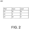
- FIG. 2 shows an example database table 200 representing the 2-hierarchy level tree-like structure 100 of a document flow.
- Table 200 may be assembled using, for example, Advanced Business Application Programming (ABAP) language and SQL commands.
- Table 200 may be made available to users as an ABAP consumable.
- table 200 may include rows indicating that order document O1 and shipping document S1 are directly related as predecessor (pred) and successor (succ) objects in hierarchy level 00, shipping document S1 and invoice document I1 are directly related as predecessor and successor objects in hierarchy level 01, and further shipping document S1 and goods movement document G1 (I1) are also directly related as predecessor and successor objects in hierarchy level 01.
- ABAP Advanced Business Application Programming
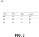
- FIG. 3 shows another example database table 300 of the 2-hierarchy level tree-like structure 100 of FIG. 1 .
- Table 300 like table 200 may be made available to users as an ABAP consumable.
- Table 300 may be an extension or enrichment of table 200 ( FIG. 2 ) by further including the root node (e.g., O1) as a column or key in the table.
- the root node e.g., O1
- Such extension or enrichment of the database table may be useful, for example, when multiple hierarchies for multiple roots are selected for inclusion or querying in the database tables.
- Including the root node (e.g., O1) as a column or key in the table may advantageously allow data for the multiple hierarchies to be read in one select/round-trip to the database.
- FIG. 4 is a schematic block diagram showing an example business application system including a relational database stored in a memory 470 of a database system 420, in accordance with the principles of the present disclosure.
- the database system comprises a computing device 47 (e.g. one or more computer microprocessors) to execute a processor executable program code in order to operate the relational database and/or execute steps of computer-implemented methods described herein.
- the computer executable code can be stored in the memory 470 of the database system 420.
- System 400 may include a business application 440 coupled to relational database.
- Business application 440 may generate business transactions data (e.g., documents) to be stored in relational database and/or may consume the business transactions data stored in relational database.
- the database comprises memory 470 storing sets of electronic documents.
- Business application 440 may, for example, be hosted or launched on a computer 410.
- Computer 410 which includes an O/S 41 b, a CPU 42b, a memory 43b, and I/O 44b, may further include a user interface (UI) or display 45.
- UI user interface
- computer 410 is illustrated in the example of FIG. 4 as a single computer, it may be understood that computer 410 may represent two or more computers in communication with one another. Therefore, it will also be appreciated that any two or more components 420-440 of system 400 may similarly be executed using some or all of the two or more computers in communication with one another. Conversely, it also may be appreciated that various components illustrated as being external to computer 410 may actually be implemented therewith.
- business application 440 may be an application, which can run on computer 410 or, for example, in another computing environment (e.g., Backend system 430/Server 432).
- a hierarchical data model may assign a hierarchical tree-like structure to the business transactions data that may be stored in a form of electronic documents in relational database with each branch (or sub branch) of the tree representing a direct object-object (parent-child) relationship.
- the parent-child relationship data may be stored in a table (e.g., Table 422) in a format, which, for example, is similar to that of table 200 ( FIG. 2 ).
- Consumable representations e.g., similar in format to table 200 or table 300
- the electronic documents can be grouped in sets, each having its own hierarchical structure of the electronic documents.
- the database or table may be constructed using ANSI-SQL compatible declarations (e.g., Open-SQL declarations), in accordance with the principles of the present disclosure.
- ANSI-SQL compatible declarations e.g., Open-SQL declarations
- Predecessor objects and successor objects in the database or table may, for example, be defined as follows.
- a pre-determined number of hierarchy levels may be included in the tree-like structure representation of the data in the database or table (e.g., Table 422).
- the database or table may be configured using the ANSI-SQL compatible declarations so that a single database view (or query) can retrieve a complete hierarchical view of the data.
- the documents database may be a relational database that includes only direct object-object (parent-child) relationships data for a pre-determined number of hierarchy levels "n" (as shown, for example, in Table 200), or may be a database (e.g., a legacy database) that includes additional data (e.g., data on indirect relationships).
- the documents database or table may be dynamic or volatile database, and may contain a large number of data records, which may be updated frequently.
- a database view (or a stored query) may be established to view or extract selected data from the database e.g., from table 422 storing parent-child relationships of the electronic documents) consistent with the hierarchical data model described herein.
- the result set (a virtual table) may be computed or collated dynamically on the fly from current data in the database when access to that database view is requested, for example, by the business application.
- the result set may be returned as a consumable to the business application.
- a single database view may configured to view or access a complete set of documents data spanning a pre-determined number M of hierarchical levels in the database (e.g., Table 422).
- the single database view may include SQL self-join commands to self join the database table (i.e. the database table storing parent-child relationships, e.g. table 422) N times to iteratively generate data records level-by-level for hierarchy levels up to N.
- database table i.e. the database table storing parent-child relationships, e.g. table 422
- the database view (query, e.g. SQL query), which may, for example, be written in Data Descriptive Language (DDL), may be coded to limit access to the selected data (or the predetermined number of M of hierarchical levels) in the database by using "where" clauses in the "select" statements in the database view (query, e.g. SQL query) DDL declaration.
- the predetermined number of M of hierarchical levels for the database view (query, e.g. SQL query) may be specified at design time.
- An example portion of a DDL declaration for a database view (query, e.g. SQL query) to view or retrieve document data for the M hierarchical levels (e.g., including levels L00 and L01) in the database table ("relation-table”, e.g. "relation-table” on Fig. 9 ) may be as follows:
- a specific "union all" branch may be declared for each of the M hierarchy levels to collect or view only the data for the corresponding hierarchy level.
- a nested self-join condition may be used in the "union all" branch for level 'm', which first retrieves the rows representing level 'm-1' in the database table. These rows representing level 'm-1' may be then joined with the database table again, to determine the rows representing level 'm'. For each of the M levels, the nesting-depth in the foregoing DDL declaration is increased by one.
- the final hierarchy may be obtained by merging the sub-result sets of all levels, 1 to M, using the last "union all" declaration. From a declarative perspective, selecting the sub-result set for each of the M levels (as in the foregoing DDL declaration) can be executed independently and therefore in parallel. However, from an execution perspective, doing so may result in redundant, identical operations (e.g., in the nested joins in the "union all" branches up to level 'm-1' when executing level 'm'). However, the computing platform used for executing the database view (query) (e.g., database and application platform HANA) may take these possible redundant, identical operations into consideration to reduce sequential operations when establishing an optimal query plan.
- database view e.g., database and application platform HANA
- An example query plan (e.g., in HANA) may be based on the recognition that the complete set of "join” operations (in a current "union all” branch in the foregoing DDL declaration) need not be executed sequentially. For some of the joins, results may be available from the join operations of a previous "union all” branch. These results could be re-used and accordingly re-execution of the previous result-producing joins may be avoided in the current "union all” branch. Only the joins for which results are not available from previous "union all” branches need to be executed in the current "union all” branch.
- the example query plan may (e.g., to reduce CPU demand) minimize or reduce sequential execution within the nested joins in the database view by limiting execution in a current "union all" branch only to those joins for which results are not be available from the execution of the previous "union all” branch.
- the example query plan may stagger or delay execution of the nested joins for the current "union all” branch based, for example, on the completion of execution of the joins in the previous "union all” branch. For example, when accessing rows in the database table for a hierarchy level 5, all rows need to be calculated within the nested joins up to level 4 (i.e. Level 0 ⁇ Level 1 ⁇ Level 2 ⁇ Level 3 ⁇ Level 4). The nested joins for levels 0-3 may have already been calculated as part of the "union all” branch for level 4.
- the staggered operations for calculation of the nested joins up to level 4 may start as soon as the nested join calculations up to level 3 (in the course of accessing level 4) are completed. Staggering the nested join operations for the different levels may reduce CPU demand. It may be expected that with the staggered operations, CPU consumption will dependent linearly on the number of levels accessed in the execution of the database view (query, e.g. SQL query).
- FIG. 5 shows an example query plan 500, which may be established in HANA, for a 6-hierarchy level database view (query, e.g. SQL query). Each independent vertical column of boxes in the figure represents a level-specific "union all" branch in the database view (query, e.g. SQL query).
- FIG. 6 shows an example timeline view 600 of the execution of query plan 500. Timeline view 600 shows the staggered execution of the join operations in the parallel "union all" branches for levels 1-5 according to query plan 500. As shown in the figure, execution of join operations (at least for level 3 to 5) show considerable overlap in time. This overlap in execution times indicates that the execution time of the database view (query) may grow at most linearly with the number of levels queried.
- Implementations of the hierarchical data model and a database view (query) were tested on a computer system, which included a HANA platform coupled to a sales documents (SD) database (e.g. table 422) having about 250 million rows of data.
- SD sales documents
- Tests were conducted to determine execution time differences between a database level representation of the data, which involves storing only the direct object-object relations (as described herein), and a conventional database level representation of the data, which involves storing the complete tree structure including redundancies.
- Another test involved determining the execution times for returning multiple complete hierarchies (i.e. five hierarchies) for five example order documents to a business application (1) when accessing the table 422 directly and (2) when accessing the table 422 via View.
- Execution of the select statements to fetch the five hierarchies by accessing the table 422 directly took about 9 ms.
- Execution of the select statement to fetch the five hierarchies via View took about 68 ms.
- fetching hierarchies from the database via View takes more time than fetching the hierarchies by direct access (e.g., 38 ms vs. 3.5 ms and 68 ms vs. 9ms).
- the times for fetching hierarchies from the database via View were still in an acceptable range on the order of tens of milliseconds (which may be below a human perception threshold, for example, when the results are displayed on a computer screen to a human user).
- FIG. 7 shows an example computer-implemented method 700 for determining a document flow of documents (e.g., business transactions documents), in accordance with the principles of the present disclosure.
- Data on the documents may be stored in a documents database or table (e.g., Table 422).
- Method 700 may include assigning a hierarchical tree-like structure to the documents stored in the documents database, according to a hierarchical data model (710).
- the hierarchical tree-like structure may include one or more hierarchy levels beginning with a document assigned to a root node of the tree-like structure.
- Each hierarchy level in the tree-like structure may be defined by direct relations between the documents assigned to pairs of tree nodes in the the hierarchy level.
- stored redundant information e.g., indirect or transitive relations between the tree nodes/documents
- this information can be dynamically calculated or reconstructed based on the stored direct relations and made available on the fly as a consumable as and when needed.
- the data on the documents (including relational data) stored in the documents database or table may include only direct relations data.
- Method 700 may further include assembling a tabular representation, for a pre-determined number of hierarchy levels, of the hierarchical tree-like structure assigned to the documents (720), and providing the tabular representation as a determination of the document flow (730).
- assembling the tabular representation 720 may include using Advanced Business Application Programming (ABAP) language and SQL commands. Further, providing the tabular representation 730 may include making the tabular representation available as an ABAP consumable and may include storing the tabular representation in the documents database.
- ABAP Advanced Business Application Programming
- assembling the tabular representation 720 may include establishing a database view (query) to view or extract selected data from the documents database, the database view being configured to compute the tabular representation when access to the database view is requested by a user.
- the database view may be written in Data Descriptive Language (DDL) and may be coded to limit access to selected data in the database (e.g. Table 422 or Table 800) by using "where" clauses in "select" statements.
- the database view may be configured to view or access a complete set of documents data spanning a specified number M of hierarchical levels in the documents database.
- the database view may include nested self-join commands to self-join a database table 1 to M times to generate data records with hierarchy levels 1 to M, respectively.
- Method 700 may further include, establishing a query plan on a computing platform to optimize execution of the database view including the self- join commands.
- the query plan may involve, for a hierarchy level (m), executing only the self-join commands for which results are not available from executions of the self-join commands for a previous hierarchy level, and staggering execution of the self-join commands for one or more of the hierarchy levels with respect to the execution of the self-join commands for another the hierarchy levels.
- FIG. 8 shows an example computer-implemented method for operating the database system 420.
- the database system comprises a memory 470 storing a relational database and a processor-executable program code.
- the relational database stores hierarchically structured sets of electronic documents. Hierarchy structures of the electronic documents in the hierarchically structured sets are determined by parent-child relationships of the electronic documents stored in the relational database as tuples identifying pairs of the electronic documents linked by the parent-child relationships. The tuples can be stored in a tuple table 800 depicted on Fig. 9 .
- the database system further comprises a computing device 47 to execute the processor executable program code in order to cause the computing device to execute the computer-implemented method.
- the computer-implemented method begins with an optional process block 900.
- a database view configured, as described above, to view or access a complete set of documents data spanning a specified number M of hierarchical levels in the documents database is generated.
- the database view can be accessed by executing the aforementioned query or an example query on Fig. 10 .
- the database view can be specified in DDL which is coded to limit access to selected data in the documents database by using "where" clauses in "select" statements.
- the database view may be configured to view or access a complete set of documents data spanning a specified number M of hierarchical levels in the documents database.
- the database view may include nested self-join commands to self-join a database table 1 to M times to generate data records with hierarchy levels 1 to M, respectively.
- Process block 901 is executed after process block 900 if the latter is executed otherwise execution of the computer-implemented method begins with process block 901.
- a data request for retrieving of a hierarchical structure 100 of the parent-child relationships of one of the sets of the electronic documents e.g. a set of the electronic documents on Fig. 1
- the data request specifies a starting (root) electronic document in said hierarchical structure, e.g. electronic document O1 on Fig. 1 .
- the data request can be received from a computer system (e.g. computer system 410) via a computer network.
- Process block 902 is executed in response to execution of process block 900.
- a step of identifying a child set of electronic documents is repetitively executed. Wherein for each of the repetitive executions a child set of electronic documents is identified.
- Each of the electronic documents of the child set e.g. electronic document S1 in the table on Fig. 2
- has a respective parent-child relationship e.g. parent-child relationship of level '00' on Fig. 1
- one of the electronic documents of a parent set of electronic documents e.g. electronic document O1 in the table on Fig. 2 .
- the repetitive execution of the identifying of the child set is executed until it results in an empty child set.
- the parent set consists of the starting (root) electronic document (e.g.
- the child set of the current repetition e.g. electronic document S1 in the first row of the table on Fig. 2
- the parent set of the next following repetition e.g. electronic document S1 in the second and third row of the table on Fig. 2
- Process block 902 can be executed using the SQL query mentioned above or the SQL query 806 depicted on Fig. 10 .
- the table depicted on Fig. 3 is generated.
- the table on Fig. 3 can constitute the table view of process block 900.
- the queries can be formulated using the ANSI-SQL commands, or their compatible ones.
- All parent-child relationships e.g. parent-child relationships of level '01' on Fig. 1 ) of the electronic documents of the parent set (e.g. document S1 on Fig. 1 ) with the electronic documents of the child set (e.g. documents I1 and G1 on Fig. 1 ) identified in any repetitively executed step of the identifying of the child set of electronic documents, which execution resulted in a non-empty child set, (e.g. second execution of the identifying of the child set of electronic documents) have a hierarchy level (e.g. level '01' on Fig. 1 ) in said hierarchical structure being one hierarchy level lower in said hierarchical structure than all parent - child relationships (e.g.
- Each of the identification of the child set of the electronic documents in the process of the repetitive executing of the identifying of the child set of electronic documents can have a respective fragment of the SQL query configured to identify the child set of the electronic documents identified in the each of the identification of the child set of the electronic documents.
- a fragment of the example SQL query (lines 811-815) can generate the first row in the Table on Fig. 3 and another fragment of the example SQL query (lines 818 - 829) can generate the second and the third rows in the Table on Fig. 3 .
- Each of the fragments of the SQL query except the fragment of the SQL query corresponding to the first executed identification of the child set of the electronic documents in the process of the repetitive executing of the identifying of the child set of electronic documents e.g.
- lines 811 - 815 in the example query 806) comprises a respective sequence of recurrent requests (e.g. lines 818-823 and lines 824-827 in the example query 806) having at least first request of the sequence and the last request of the sequence.
- the first request e.g. lines 824-827 in the example query 806) comprises one or more SQL select commands (e.g. lines 824-826 in the example query 806) being configured to identify the child set of electronic documents having the starting (root) electronic document as a parent electronic document by retrieving form the tuple table (e.g. relation-table 800) an auxiliary tuple table 850 of tuples in each of which the starting electronic document is specified as a parent electronic document.
- the tuple table e.g. relation-table 800
- an auxiliary tuple table 850 of tuples in each of which the starting electronic document is specified as a parent electronic document.
- every next request (including the last one) in the sequence of recurrent requests comprises one or more SQL select commands (e.g. lines 818-823 of the query 806 ) configured to identify the child set of the electronic documents each having parent-child relationship with one of electronic documents of the child set identified in the previous request in the sequence of recurrent requests by retrieving an auxiliary tuple table (e.g. table 860 on Fig. 12 ) of tuples in each of which one of the electronic documents of the child set identified in the previous request is specified as a parent electronic document from a table generated using an SQL join command (e.g. lines 828 and 829 in query 806) of an auxiliary tuple table (e.g.
- each of the last requests is configured to identify the child set identified in the respective execution of the step of the identification of the child set of electronic documents.
- each of the sequences of recurrent requests is based on nested self-join SQL commands (e.g.
- the fragment of the SQL query corresponding to the first executed identification of the child set of the electronic documents in the process of the repetitive executing of the identifying of the child set of electronic documents comprises only the request being substantially similar or the same as the first requests in the sequences of the recurrent requests.
- This request comprises one or more SQL select commands (e.g. lines 811-815) being configured to identify the child set of electronic documents having the starting electronic document as a parent electronic document by retrieving form the tuple table (e.g. table 800) an auxiliary tuple table (e.g. table 850) of tuples in each of which the starting (root) electronic document is specified as a parent electronic document.
- the SQL query can further comprise SQL union all commands (e.g. lines 816, 830, 835 in query 806) configured to unite in a hierarchy table (e.g. table on Fig. 3 ) the following tables: the auxiliary tuple table (e.g. Table 850) generated in the first request comprised in the fragment of the SQL query corresponding to the first execution of the identification of the child set of electronic documents and all auxiliary tuple tables (e.g. table 860) generated in one or more of the last requests corresponding to each of the fragments of the SQL query except the fragment of the SQL query corresponding to the first executed identification of the child set of the electronic documents in the process of the repetitive executing of the identifying of the child set of electronic documents.
- SQL union all commands e.g. lines 816, 830, 835 in query 806
- a hierarchy table e.g. table on Fig. 3
- the auxiliary tuple table e.g. Table 850
- all auxiliary tuple tables e.
- the query can be configured such that the hierarchy table (e.g. table on Fig. 3 ) represents said hierarchy structure (e.g. structure of electronic documents depicted on Fig. 1 ).
- the hierarchy table e.g. table on Fig. 3
- said hierarchy structure e.g. structure of electronic documents depicted on Fig. 1 .
- lines 814 and 822 are added in order to generate the 'level' column in the table on Fig. 3 .
- the repetitive executing of the identifying of the child set of electronic documents can comprise generating a query plan on the computing device 47 for the repetitive executing of the identifying of the child set of electronic documents, wherein the repetitive execution of the identifying of the child set of electronic documents is executed according to the query plan, wherein the query plan involves, for any hierarchy level except the first one in said hierarchical structure, executing only the nested self-join commands for which results are not available from executions of the nested self-join commands for a hierarchy level being one level higher than the any hierarchy level in said hierarchical structure.
- the query plan can comprise staggering execution of the nested self-join commands (e.g.
- the SQL query can be executed according to the following query plan, in which execution of the fragment of the SQL query (e.g. lines 811-815 in query 806) corresponding to the first execution of the identification of the child set of the electronic documents is scheduled first. Afterwards the execution of only the last request in each of the aforementioned fragments of the SQL query is scheduled, wherein execution of the last requests is scheduled in the same sequence as their respective steps of the identification of the child set of the electronic documents are executed in the process of the repetitive executing of the identifying of the child set of electronic documents.
- execution of the fragment of the SQL query e.g. lines 811-815 in query 806
- execution of only the last request in each of the aforementioned fragments of the SQL query is scheduled, wherein execution of the last requests is scheduled in the same sequence as their respective steps of the identification of the child set of the electronic documents are executed in the process of the repetitive executing of the identifying of the child set of electronic documents.
- the auxiliary tuple table to be retrieved according to the query pan in the execution of the last request of any of the fragments of the SQL query except the fragment of the SQL query scheduled first for execution in the query plan is scheduled to be used as the auxiliary tuple table for the execution of the last request of the fragment of the SQL query scheduled for execution in the query plan after the last request of the any of the fragments of the SQL query except the fragment of the SQL query scheduled first for execution in the query plan.
- results obtained as result of execution of one of the last requests in the fragment of the SQL query are used directly for the execution of the next last request of another fragment of the SQL query without the need to execute any of the previous requests in the sequence of recurrent requests of the another fragment of the SQL query.
- the lines 824 - 827 are not scheduled for execution, instead the results of execution of lines 811 - 815 are used as a substitute of the execution of the lines 824-827.
- process block 903 is executed after process block 902.
- said hierarchical structure is returned as a plurality of tuples determining parent - child relations between the electronic documents of all pairs of the child and the parent sets identified in process block 902.
- the plurality of tuples can be sent to the computer system via the computer network.
- the plurality of tuples can be returned in a form of the hierarchy table mentioned above.
- the plurality of tuples can be returned in a form of the aforementioned database view as well.
- the various systems and techniques described herein may be implemented in digital electronic circuitry, or in computer hardware, firmware, or in combinations of them.
- the various techniques e.g., method 700 or method on Fig. 8
- may implemented via a computer program product i.e. a computer program with instructions tangibly embodied in a machine readable storage device, for execution by, or to control the operation of, data processing apparatus, e.g., a programmable processor, a computer, or multiple computers.
- Method steps may be performed by one or more programmable processors executing a computer program to perform functions by operating on input data and generating output. Method steps also may be performed by, and an apparatus may be implemented as, logic circuitry or special purpose logic circuitry, e.g., an FPGA (field programmable gate array) or an ASIC (application specific integrated circuit).
- FPGA field programmable gate array
- ASIC application specific integrated circuit
- processors suitable for the execution of a computer program include, by way of example, both general and special purpose microprocessors, and any one or more processors of any kind of digital computer.
- a processor will receive instructions and data from a read only memory or a random access memory or both.
- Elements of a computer may include at least one processor for executing instructions and one or more memory devices for storing instructions and data.
- a computer also may include, or be operatively coupled to receive data from or transfer data to, or both, one or more mass storage devices for storing data, e.g., magnetic, magnetooptical disks, or optical disks.
- Information carriers suitable for embodying computer program instructions and data include all forms of nonvolatile memory, including by way of example semiconductor memory devices, e.g., EPROM, EEPROM, and flash memory devices; magnetic disks, e.g., internal hard disks or removable disks; magnetooptical disks; and CDROM and DVD-ROM disks.
- semiconductor memory devices e.g., EPROM, EEPROM, and flash memory devices
- magnetic disks e.g., internal hard disks or removable disks
- magnetooptical disks e.g., CDROM and DVD-ROM disks.
- the processor and the memory may be supplemented by, or incorporated in special purpose logic circuitry.
- implementations may be implemented on a computer having a display device, e.g., a cathode ray tube (CRT) or liquid crystal display (LCD) monitor, for displaying information to the user and a keyboard and a pointing device, e.g., a mouse or a trackball, by which the user can provide input to the computer.
- a display device e.g., a cathode ray tube (CRT) or liquid crystal display (LCD) monitor
- keyboard and a pointing device e.g., a mouse or a trackball
- Other kinds of devices can be used to provide for interaction with a user as well; for example, feedback provided to the user can be any form of sensory feedback, e.g., visual feedback, auditory feedback, or tactile feedback; and input from the user can be received in any form, including acoustic, speech, or tactile input.
- Implementations may be implemented in a computing system that includes a backend component, e.g., as a data server, or that includes a middleware component, e.g., an application server, or that includes a frontend component, e.g., a client computer having a graphical user interface or a Web browser through which a user can interact with an implementation, or any combination of such backend, middleware, or frontend components.
- Components may be interconnected by any form or medium of digital data communication, e.g., a communication network. Examples of communication networks include a local area network (LAN) and a wide area network (WAN), e.g., the Internet.
- LAN local area network
- WAN wide area network
Landscapes
- Engineering & Computer Science (AREA)
- Databases & Information Systems (AREA)
- Theoretical Computer Science (AREA)
- Data Mining & Analysis (AREA)
- Physics & Mathematics (AREA)
- General Engineering & Computer Science (AREA)
- General Physics & Mathematics (AREA)
- Operations Research (AREA)
- Computational Linguistics (AREA)
- Business, Economics & Management (AREA)
- General Business, Economics & Management (AREA)
- Information Retrieval, Db Structures And Fs Structures Therefor (AREA)
Abstract
Description
- The present disclosure relates to relational databases systems storing hierarchically structured sets of electronic documents. In particular, the present disclosure relates to effective storage and retrieval of hierarchy of electronic documents.
- Relational databases can store a lot of electronic documents. The electronic documents can be linked by parent-child relations in hierarchically ordered sets of electronic documents. A number of electronic documents stored in such relational databases can in the range of millions or even billions, e.g. for applications such as applications for customer relationship management, human resource management, outsourcing relationship management, field service management, enterprise resource planning (ERP), enterprise content management (ECM), business process management (BPM), product lifecycle management, etc.. The electronic documents may contain a large number of document types (e.g., orders, shipping documents, invoices, goods movements, etc.). As a result thereof relational data describing parent-child relationships of the electronic documents becomes very big and complex and its usage requires considerable computer resources. Moreover the relational data can rapidly change in time, e.g. when new electronic documents are added to the relational database and/or the parent-child relationships between the electronic documents are changed.
- For example, in the case of sales-related business transactions, individual transactions (e.g., inquiry, quotation, sales order, shipment, invoice, and returns, etc.) may be stored as individual sales documents (SD) in a "documents" or "documents flow" database. The relational data (so-called document flow or history) linking various individual documents may be stored in a database table linking various individual documents. An entire chain of sales documents (e.g., inquiry, quotation, sales order, shipment, invoice, and returns, etc.) may create a document flow or history. In such case, the stored relational data may include direct relations between individual documents (e.g., "order leading to shipment," "shipment leading to invoice," etc.). Additionally, the stored relational data may include indirect or transitive relations (e.g., "order indirectly leading to invoice," etc.). The indirect or transitive relations ("redundant data") can be a large portion (e.g., 50%) of the stored data. In scenarios which involve a large number of documents, the memory requirements for storing the redundant data can be onerous.
Almost any operation on the electronic documents executed by an application or a computer program requires evaluation of their hierarchic relations with other documents. As a result thereof processing of the hierarchic relations might cause substantial work load of the relational database. - A database system and a method of its operation are described herein. Hierarchic parent-child relationships of electronic documents stored in the relational database are stored in a compact structure enabling effective retrieval of hierarchic structures of sets of the electronic documents. Although the hierarchic parent-child relations are stored in a simple and a compact format, it is possible to retrieve a hierarchic structure of a set of the electronic documents using a universal method which can be implemented using various hardware and software platforms. Moreover execution of this universal algorithm requires very little computer resources. In the other words the format for storing parent-child relationships in conjunction with said method enables to address objectives of contradictory nature, because as usual compact (expanded) storage of data and/or its structure increases (decreases) access time to it.
- It is an objective of embodiments of the invention to provide for a database system configured to provide access to hierarchic structure of hierarchically structured sets of electronic documents stored in the relational database, a computer-implemented method for providing access to said hierarchic structure, and a computer readable medium having stored thereon a computer executable program code for providing access to said hierarchic structure. Advantageous embodiments are described in the dependent claims.
- According to one embodiment, the present invention relates to a database system comprising a memory storing a relational database and a processor-executable program code, the relational database storing hierarchically structured sets of electronic documents, wherein hierarchy structures of the electronic documents in the hierarchically structured sets are determined by parent-child relationships of the electronic documents stored in the relational database as tuples identifying pairs of the electronic documents linked by the parent-child relationships, and a computing device to execute the processor executable program code in order to cause the computing device to execute the following steps of a computer-implemented method: receiving a data request for retrieving of a hierarchical structure of the parent-child relationships of one of the sets of the electronic documents, the data request specifying a starting electronic document in said hierarchical structure; in response to the receiving of the data request for retrieving of said hierarchical structure of the parent-child relationships in one of the sets of the electronic documents repetitively executing the following step of identifying a child set of electronic documents, wherein each of the electronic documents of the child set has a respective parent-child relationship with one of the electronic documents of a parent set of electronic documents, until the execution of the identifying of the child set results in an empty child set, wherein the parent set consists of the starting electronic document when the identifying of the child set is executed for the first time, wherein the child set of the current repetition and the parent set of the next following repetition are the same; and returning said hierarchical structure as a plurality of tuples determining parent - child relations between the electronic documents of all pairs of the child and the parent sets identified in the process of the repetitive executing of the identifying of the child set of electronic documents.
- According to another embodiment, the present invention relates to a computer-implemented method for operating a database system comprising: a memory storing a relational database and a processor-executable program code, the relational database storing hierarchically structured sets of electronic documents, wherein hierarchy structures of the electronic documents in the hierarchically structured sets are determined by parent-child relationships of the electronic documents stored in the relational database as tuples identifying pairs of the electronic documents linked by the parent-child relationships, and a computing device to execute the processor executable program code in order to cause the computing device to execute the computer-implemented method, the computer-implemented method comprising: receiving a data request for retrieving of a hierarchical structure of the parent-child relationships of one of the sets of the electronic documents, the data request specifying a starting electronic document in said hierarchical structure; in response to the receiving of the data request for retrieving of said hierarchical structure of the parent-child relationships in one of the sets of the electronic documents repetitively executing the following step of identifying a child set of electronic documents, wherein each of the electronic documents of the child set has a respective parent-child relationship with one of the electronic documents of a parent set of electronic documents, until the execution of the identifying of the child set results in an empty child set, wherein the parent set consists of the starting electronic document when the identifying of the child set is executed for the first time, wherein the child set of the current repetition and the parent set of the next following repetition are the same; and returning said hierarchical structure as a plurality of tuples determining parent - child relations between the electronic documents of all pairs of the child and the parent sets identified in the process of the repetitive executing of the identifying of the child set of electronic documents.
- According to another embodiment, the present invention relates to a computer readable medium having stored thereon a computer executable program code for execution by a computer processor controlling a computing device of a database system, wherein execution of the instructions of the executable program code causes the computer processor controlling the computing device to perform the computer-implemented method of the aforementioned embodiment on the database system.
- The aforementioned embodiments are advantageous because they can provide compact storage of parent-child relations of the electronic documents in the relational database in conjunction with effective procedure of retrieving of the parent-child relationships and the whole hierarchic structure from the relational database.
- In another embodiment all parent-child relationships of the electronic documents of the parent set with the electronic documents of the child set identified in any repetitively executed step of the identifying of the child set of electronic documents, which execution resulted in a non-empty child set, have a hierarchy level in said hierarchical structure being one hierarchy level lower in said hierarchical structure than all parent - child relation-ships of the electronic documents of the parent set with the electronic documents of the child set identified in the step of the identifying of the child set of electronic documents executed immediately before the any repetitively executed step of the identifying of the child set of electronic documents.
- This embodiment can be advantageous because it can provide extra structuring of the parent-child relationships in said hierarchic structure.
- In another embodiment, the receiving of the data request for retrieving of said hierarchical structure of the parent-child relationships in one of the sets of the electronic documents the data request comprises receiving on the database system from a computer system via a computer network, wherein the returning of said hierarchical structure as the plurality of tuples determining parent - child relations between the electronic documents of all pairs of the child and the parent sets identified in the process of the repetitive executing of the identifying of the child set of electronic documents comprises sending the plurality of tuples to the computer system via the computer network.
- This embodiment is advantageous, because in order to get said hierarchical structure the computer system can specify only the starting (root) document of the set of the electronic documents, while the database system performs the retrieval of said hierarchical structure according to internal standardized procedure.
- In another embodiment, a process of the repetitive executing of the identifying of the child set of electronic documents is executed in a form of an Structured Query Language, SQL, query of the relational database, wherein the tuples are stored as a tuple table in the relational data base, wherein each of the identification of the child set of the electronic documents in the process of the repetitive executing of the identifying of the child set of electronic documents has a respective fragment of the SQL query configured to identify the child set of the electronic documents identified in the each of the identification of the child set of the electronic documents, wherein each of the fragments of the SQL query except the fragment of the SQL query corresponding to the first executed identification of the child set of the electronic documents in the process of the repetitive executing of the identifying of the child set of electronic documents comprises a respective sequence of recurrent requests having a first request comprising one or more SQL select commands being configured to identify the child set of electronic documents having the starting electronic document as a parent electronic document by retrieving form the tuple table an auxiliary tuple table of tuples in each of which the starting electronic document is specified as a parent electronic document, wherein the first request is a first request in the respective sequence of recurrent requests, and a last request configured to identify the child set of the electronic documents which is identified in the execution of the identification of the electronic documents corresponding to the each of the fragments of the SQL query except the fragment of the SQL query corresponding to the first executed identification of the child set of the electronic documents in the process of the repetitive executing of the identifying of the child set of electronic documents, wherein the last request is a first request in respective sequence of recurrent requests, wherein every next request in the sequence of recurrent requests comprises one or more SQL select commands being configured to identify the child set of the electronic documents each having parent-child relationship with one of electronic documents of the child set identified in the previous request in the sequence of recurrent requests by retrieving an auxiliary tuple table of tuples in each of which one of the electronic documents of the child set identified in the previous request is specified as a parent electronic document from a table generated using an SQL join command of an auxiliary tuple table retrieved in the previous request and the tuple table having a join condition specifying that all of the electronic documents specified as child electronic documents in one or more tuples of the auxiliary tuple table retrieved in the previous request are specified as parent electronic documents in one or more tuples of the tuple table, wherein the fragment of the SQL query corresponding to the first execution of the identification of the child set of electronic documents comprises only the first request.
- This embodiment can be advantageous because it describes a universal SQL query which can be used for processing of the data requests regarding hierarchic structure of different sets of electronic documents. Yet another advantage of this embodiment can be a compact storage of the parent-child relations in a single table, which avoids storing redundant/duplicating/repetitive information. Adding a new electronic document to a set of electronic documents can require adding of only one additional tuple in the tuple table. Changes in the hierarchy in a set of the electronic documents requires changes only of relevant tuples without causing a consequent cascade of updates and/or changes.
- In another embodiment, the SQL query comprises SQL union all commands configured to unite in a hierarchy table: the auxiliary tuple table generated in the first request comprised in the fragment of the SQL query corresponding to the first execution of the identification of the child set of electronic documents and all auxiliary tuple tables generated in one or more of the last requests corresponding to each of the fragments of the SQL query except the fragment of the SQL query corresponding to the first executed identification of the child set of the electronic documents in the process of the repetitive executing of the identifying of the child set of electronic documents, wherein said hierarchical structure returned in the returning of said hierarchical structure as the plurality of tuples determining parent - child relations between the electronic documents of all pairs of the child and the parent sets identified in the process of the repetitive executing of the identifying of the child set of electronic documents is the hierarchy table.
- This embodiment can be advantageous because said hierarchic structure is retrieved as a result of execution of the single SQL query without the need to store intermediate results related to different hierarchy levels.
- In another embodiment, the SQL query is executed according to a query plan, in which execution of the fragment of the SQL query corresponding to the first execution of the identification of the child set of the electronic documents is scheduled first, after the execution of the fragment of the SQL query corresponding to the first execution of the identification of the child set of the electronic documents execution of only the last request in each of the fragments of the SQL query is scheduled in the same sequence as their respective steps of the identification of the child set of the electronic documents in the process of the repetitive executing of the identifying of the child set of electronic documents, wherein the auxiliary tuple table to be retrieved according to the query pan in the execution of the last request of any of the fragments of the SQL query except the fragment of the SQL query scheduled first for execution in the query plan is scheduled to be used as the auxiliary tuple table for the execution of the last request of the fragment of the SQL query scheduled for execution in the query plan after the last request of the any of the fragments of the SQL query except the fragment of the SQL query scheduled first for execution in the query plan.
- This embodiment can be advantageous, because it can provide an effective plan for query execution. The results generated as a result of evaluation of one of the hierarchy levels are used for evaluation of the next hierarchy levels. As a result thereof unnecessary repetition of the SQL query commands is avoided.
- In another embodiment, the SQL is an American National Standards Institute SQL, ANSI-SQL.
- This embodiment can be advantageous, because it specifies one of the most recognized dialects of SQL. As a result thereof the retrieving of said hierarchical structure can be implemented using a broad spectrum of software and/or hardware platforms.
- In another embodiment, a number of hierarchy levels in any of the sets of electronic documents is less or equal to a maximum predefined number of hierarchy levels.
- This embodiment can be advantageous because it can provide for a standardized SQL query for retrieving of the hierarchical structure of any of the sets of electronic documents stored in the relational database.
- In another embodiment the repetitive executing of the identifying of the child set of electronic documents comprises execution of commands of American National Standards Institute Structured Query Language, ANSI-SQL.
- This embodiment can be advantageous, because it specifies one of the most recognized dialects of SQL. As a result thereof the retrieving of said hierarchical structure can be implemented using a broad spectrum of software and/or hardware platforms.
- In another embodiment, said hierarchical structure returned in the returning of said hierarchical structure as a plurality of tuples determining parent - child relations between the electronic documents of all pairs of the child and the parent sets identified in the process of the repetitive executing of the identifying of the child set of electronic documents is formulated as an Advanced Business Application Programming, ABAP, consumable.
- This embodiment can be advantageous, because it provides for an output format which is compatible with the widely used ABAP.
- In another embodiment, the computer-implemented method comprises generating a database view configured to view or access a complete set of documents data spanning a specified number M of hierarchical levels in the documents database, wherein said hierarchical structure returned in the returning of said hierarchical structure as a plurality of tuples determining parent - child relations between the electronic documents of all pairs of the child and the parent sets identified in the process of the repetitive executing of the identifying of the child set of electronic documents is returned in a form of the database view.
- This embodiment can be advantageous, because it provides for a universal template (the database view) for retrieving a hierarchic structure of any stet of electronic documents. The universal template can require very little memory space and can be stored in the relational database.
- In another embodiment, wherein the database view is specified in Data Descriptive Language, DDL, and is coded to limit access to selected data in the documents database by using "where" clauses in "select" statements.
- This embodiment can be advantageous, because the database view is formulated in a widely spread DDL using a limited number of operands in a repetitive way. As a result thereof an effective query plan can be generated.
- In another embodiment the repetitive executing of the identifying of the child set of electronic documents comprises assessing of the database view via execution of a Structured Query Language, SQL, query comprising nested self-join commands of American National Standards Institute SQL, ANSI-SQL, to self-join a database table 1 to M times to generate data records with
hierarchy levels 1 to M, respectively, the database table storing tuples. - This embodiment can be advantageous because it can provide for a standardized SQL query for retrieving of the hierarchical structure of any of the sets of electronic documents stored in the relational database. Another advantage of this embodiment can be utilization of nested self-join commands which use the same table. Repetition of the same commands using the same table can enable generation of an effective query plan in conjunction with effective utilization of memory space, i.e. without the need to reserve memory space for storing intermediate results.
- In another embodiment, the repetitive executing of the identifying of the child set of electronic documents comprises: generating a query plan on the computing device for the repetitive executing of the identifying of the child set of electronic documents, wherein the repetitive execution of the identifying of the child set of electronic documents is executed according to the query plan, wherein the query plan involves, for any hierarchy level except the first one in said hierarchical structure, executing only the nested self-join commands for which results are not available from executions of the nested self-join commands for a hierarchy level being one level higher than the any hierarchy level in said hierarchical structure.
- This embodiment can be advantageous, because it can provide an effective plan for query execution. The results generated as a result of evaluation of one of the hierarchy levels are used for evaluation of the next hierarchy levels. As a result thereof unnecessary repetition of the SQL query commands is avoided.
- In another embodiment, the query plan comprises staggering execution of the nested self-join commands for one or more of the hierarchy levels with respect to the execution of the self-join commands for another the hierarchy levels.
- The latter 2 embodiments can be advantageous, because they can provide an effective plan for query execution. The results generated as a result of evaluation of one of the hierarchy levels are used for evaluation of the next hierarchy levels. As a result thereof unnecessary repetition of the SQL query commands is avoided. The details of one or more implementations are set forth in the accompanying drawings and the description below. Further features of the disclosed subject matter, its nature and various advantages will be more apparent from the accompanying drawings, the following detailed description, and the claims.
-
-
FIG. 1 is an illustration of an example hierarchical tree-like structure that may be assigned by a hierarchical data model to sales transactions data. -
FIG. 2 is a tabular representation of a 2- hierarchy level tree-like structure model of a document flow. -
FIG. 3 is another tabular representation of the 2-hierarchy level tree-like structure model of the document flow ofFIG. 2 . -
FIG. 4 is a schematic block diagram showing an example business application computer system including a relational database. -
FIG. 5 is a schematic illustration of an example query plan, which may be established on a computing platform for executing a database view. -
FIG. 6 is an illustration of an example timeline view of the execution of the example query plan ofFIG. 5 . -
FIG. 7 illustrates an example computer-implemented method. -
FIG. 8 illustrates an example computer-implemented method. -
FIG. 9 illustrates an example tuple table. -
FIG. 10 illustrates an example SQL query. -
FIG. 11 illustrates an example auxiliary tuple table. -
FIG. 12 illustrates an example auxiliary tuple table. - In the following description, reference is made to the accompanying drawings that form a part hereof, and in which is shown by way of illustration specific embodiments which may be practiced. These embodiments are described in sufficient detail to enable those skilled in the art to practice the invention, and it is to be understood that other embodiments may be utilized and that structural, electrical, and optical changes may be made without departing from the scope of the present invention. The following description of example embodiments is, therefore, not to be taken in a limited sense, and the scope of the present invention is defined by the appended claims.
- A hierarchical data model is used to assign a hierarchical tree-like structure to relational "business transactions data" or "documents" data that may be consumed by a business application or may be stored in a database, in accordance with the principles of the present disclosure.
- Beginning with a root node object, each branch (or sub branch) of the tree-like structure may represent a direct object-object relation in the data. The hierarchical tree-like structure may include several levels of hierarchy with each level defined by the direct relations between the pairs of tree nodes/objects in the level.
- For convenience in description herein, the terms "database", "table" and "database table" may be used interchangeably herein. Further, the terms "business transactions data" and "documents" may be used interchangeably herein.
-
FIG. 1 shows, for example, a hierarchical tree-like structure that may be assigned by the hierarchical data model to the data in a use case involving sales transactions data. The sales transactions data may include objects or documents such as orders, shipping documents, invoices, goods movements, etc. These documents may relate to each other as predecessor and successor. For example, an order document (predecessor) may lead to a shipment document (successor). The shipment document (predecessor) may lead to an invoice document (successor) and/or a goods movement documents (successor).FIG. 1 schematically shows a 2-heirachy level tree-likestructure model representation 100 of the document flow in the foregoing example. In tree-likestructure model representation 100, document 101 (e.g., order O1) is the root node of the tree-like structure and document 102 (e.g., shipping document S1) is a successor object to the root node object. The predecessor-successor relationship between root node (document 101) of the tree-like structure and document 102 may define a first level of the hierarchy starting from the root node. Document 102 (e.g., shipping document S1) has predecessor-successor relationships with document 103 (e.g., invoice document I1) and document 104 (e.g., goods movement document G1). These predecessor-successor relationships may define a second level of the hierarchy starting from the root node. (For convenience, the first level and the second level of the hierarchy are visually labeled inFIG. 1 as "Level 00" and "Level 01," respectively). - With reference to the 2-heirachy level tree-like structure model representation shown in
FIG. 1 , it will be noted that if document 102 (e.g., shipping document S1) were to be considered to be a root node of a sub-tree, the predecessor-successor (parent-child) relationships between shipping document S1 anddocuments - Only direct object-object (parent-child) relationships for a predetermined number of hierarchy levels "n" may be stored in a business application database or table constructed or assembled under the foregoing hierarchical data model, in accordance with the principles of the present disclosure.
-
FIG. 2 shows an example database table 200 representing the 2-hierarchy level tree-like structure 100 of a document flow. Table 200 may be assembled using, for example, Advanced Business Application Programming (ABAP) language and SQL commands. Table 200 may be made available to users as an ABAP consumable. As shown inFIG. 2 , table 200 may include rows indicating that order document O1 and shipping document S1 are directly related as predecessor (pred) and successor (succ) objects inhierarchy level 00, shipping document S1 and invoice document I1 are directly related as predecessor and successor objects inhierarchy level 01, and further shipping document S1 and goods movement document G1 (I1) are also directly related as predecessor and successor objects inhierarchy level 01. -
FIG. 3 shows another example database table 300 of the 2-hierarchy level tree-like structure 100 ofFIG. 1 . Table 300, like table 200 may be made available to users as an ABAP consumable. Table 300 may be an extension or enrichment of table 200 (FIG. 2 ) by further including the root node (e.g., O1) as a column or key in the table. Such extension or enrichment of the database table may be useful, for example, when multiple hierarchies for multiple roots are selected for inclusion or querying in the database tables. Including the root node (e.g., O1) as a column or key in the table may advantageously allow data for the multiple hierarchies to be read in one select/round-trip to the database. -
FIG. 4 is a schematic block diagram showing an example business application system including a relational database stored in amemory 470 of adatabase system 420, in accordance with the principles of the present disclosure. The database system comprises a computing device 47 (e.g. one or more computer microprocessors) to execute a processor executable program code in order to operate the relational database and/or execute steps of computer-implemented methods described herein. The computer executable code can be stored in thememory 470 of thedatabase system 420. -
System 400 may include abusiness application 440 coupled to relational database.Business application 440 may generate business transactions data (e.g., documents) to be stored in relational database and/or may consume the business transactions data stored in relational database. The database comprisesmemory 470 storing sets of electronic documents. -
Business application 440 may, for example, be hosted or launched on acomputer 410.Computer 410, which includes an O/S 41 b, aCPU 42b, amemory 43b, and I/O 44b, may further include a user interface (UI) ordisplay 45. Althoughcomputer 410 is illustrated in the example ofFIG. 4 as a single computer, it may be understood thatcomputer 410 may represent two or more computers in communication with one another. Therefore, it will also be appreciated that any two or more components 420-440 ofsystem 400 may similarly be executed using some or all of the two or more computers in communication with one another. Conversely, it also may be appreciated that various components illustrated as being external tocomputer 410 may actually be implemented therewith. In an example scenario,business application 440 may be an application, which can run oncomputer 410 or, for example, in another computing environment (e.g.,Backend system 430/Server 432). - As noted previously, a hierarchical data model may assign a hierarchical tree-like structure to the business transactions data that may be stored in a form of electronic documents in relational database with each branch (or sub branch) of the tree representing a direct object-object (parent-child) relationship. The parent-child relationship data may be stored in a table (e.g., Table 422) in a format, which, for example, is similar to that of table 200 (
FIG. 2 ). Consumable representations (e.g., similar in format to table 200 or table 300) of the business transactions data stored in relational database may be generated on the fly and made available to users, for example, as single query responses. The electronic documents can be grouped in sets, each having its own hierarchical structure of the electronic documents. - In an example implementation, the database or table (e.g., Table 422) may be constructed using ANSI-SQL compatible declarations (e.g., Open-SQL declarations), in accordance with the principles of the present disclosure.
- Predecessor objects and successor objects in the database or table (e.g., Table 422) may, for example, be defined as follows.
- Predecessor: (Document ID (attribute VBELV), Item number (attribute POSNV), Document type (attribute VBTYP_V)).
- Successor: (Document ID (attribute VBELN), Item number (attribute POSNN), Document type (attribute VBTYP_N)).
- A pre-determined number of hierarchy levels may be included in the tree-like structure representation of the data in the database or table (e.g., Table 422). The database or table may be configured using the ANSI-SQL compatible declarations so that a single database view (or query) can retrieve a complete hierarchical view of the data.
- A business application or user may need to view or use data stored in a documents database or table. The documents database may be a relational database that includes only direct object-object (parent-child) relationships data for a pre-determined number of hierarchy levels "n" (as shown, for example, in Table 200), or may be a database (e.g., a legacy database) that includes additional data (e.g., data on indirect relationships). The documents database or table may be dynamic or volatile database, and may contain a large number of data records, which may be updated frequently.
- A database view (or a stored query) may be established to view or extract selected data from the database e.g., from table 422 storing parent-child relationships of the electronic documents) consistent with the hierarchical data model described herein. The result set (a virtual table) may be computed or collated dynamically on the fly from current data in the database when access to that database view is requested, for example, by the business application. The result set may be returned as a consumable to the business application. Consistent with the hierarchal data model described herein, a single database view may configured to view or access a complete set of documents data spanning a pre-determined number M of hierarchical levels in the database (e.g., Table 422). The single database view (query) may include SQL self-join commands to self join the database table (i.e. the database table storing parent-child relationships, e.g. table 422) N times to iteratively generate data records level-by-level for hierarchy levels up to N.
- The database view (query, e.g. SQL query), which may, for example, be written in Data Descriptive Language (DDL), may be coded to limit access to the selected data (or the predetermined number of M of hierarchical levels) in the database by using "where" clauses in the "select" statements in the database view (query, e.g. SQL query) DDL declaration. The predetermined number of M of hierarchical levels for the database view (query, e.g. SQL query) may be specified at design time.
- An example portion of a DDL declaration for a database view (query, e.g. SQL query) to view or retrieve document data for the M hierarchical levels (e.g., including levels L00 and L01) in the database table ("relation-table", e.g. "relation-table" on
Fig. 9 ) may be as follows:

- As shown for levels L00 and L01 in the example above, in the DDL declaration of the database view (query), a specific "union all" branch may be declared for each of the M hierarchy levels to collect or view only the data for the corresponding hierarchy level.
- In order to achieve this for level 'm', a nested self-join condition may be used in the "union all" branch for level 'm', which first retrieves the rows representing level 'm-1' in the database table. These rows representing level 'm-1' may be then joined with the database table again, to determine the rows representing level 'm'. For each of the M levels, the nesting-depth in the foregoing DDL declaration is increased by one.
- The final hierarchy may be obtained by merging the sub-result sets of all levels, 1 to M, using the last "union all" declaration. From a declarative perspective, selecting the sub-result set for each of the M levels (as in the foregoing DDL declaration) can be executed independently and therefore in parallel. However, from an execution perspective, doing so may result in redundant, identical operations (e.g., in the nested joins in the "union all" branches up to level 'm-1' when executing level 'm'). However, the computing platform used for executing the database view (query) (e.g., database and application platform HANA) may take these possible redundant, identical operations into consideration to reduce sequential operations when establishing an optimal query plan.
- An example query plan (e.g., in HANA) may be based on the recognition that the complete set of "join" operations (in a current "union all" branch in the foregoing DDL declaration) need not be executed sequentially. For some of the joins, results may be available from the join operations of a previous "union all" branch. These results could be re-used and accordingly re-execution of the previous result-producing joins may be avoided in the current "union all" branch. Only the joins for which results are not available from previous "union all" branches need to be executed in the current "union all" branch. Accordingly, the example query plan may (e.g., to reduce CPU demand) minimize or reduce sequential execution within the nested joins in the database view by limiting execution in a current "union all" branch only to those joins for which results are not be available from the execution of the previous "union all" branch.
- Instead of executing the sequential joins for each of the "union all" branches up to level M concurrently or in parallel, the example query plan may stagger or delay execution of the nested joins for the current "union all" branch based, for example, on the completion of execution of the joins in the previous "union all" branch. For example, when accessing rows in the database table for a
hierarchy level 5, all rows need to be calculated within the nested joins up to level 4 (i.e.Level 0 →Level 1 →Level 2 →Level 3 → Level 4). The nested joins for levels 0-3 may have already been calculated as part of the "union all" branch forlevel 4. Therefore, when accessinglevel 5, the staggered operations for calculation of the nested joins up tolevel 4 may start as soon as the nested join calculations up to level 3 (in the course of accessing level 4) are completed. Staggering the nested join operations for the different levels may reduce CPU demand. It may be expected that with the staggered operations, CPU consumption will dependent linearly on the number of levels accessed in the execution of the database view (query, e.g. SQL query). -
FIG. 5 shows anexample query plan 500, which may be established in HANA, for a 6-hierarchy level database view (query, e.g. SQL query). Each independent vertical column of boxes in the figure represents a level-specific "union all" branch in the database view (query, e.g. SQL query). Further,FIG. 6 shows anexample timeline view 600 of the execution ofquery plan 500.Timeline view 600 shows the staggered execution of the join operations in the parallel "union all" branches for levels 1-5 according toquery plan 500. As shown in the figure, execution of join operations (at least forlevel 3 to 5) show considerable overlap in time. This overlap in execution times indicates that the execution time of the database view (query) may grow at most linearly with the number of levels queried. - Implementations of the hierarchical data model and a database view (query) (similar to that described above) were tested on a computer system, which included a HANA platform coupled to a sales documents (SD) database (e.g. table 422) having about 250 million rows of data.
- Tests were conducted to determine execution time differences between a database level representation of the data, which involves storing only the direct object-object relations (as described herein), and a conventional database level representation of the data, which involves storing the complete tree structure including redundancies.
- A test involved determining the execution times for returning a complete hierarchy for one example order document to a business application (1) when directly accessing table 422 storing parent-child relationships of the electronic documents, (e.g. SD documents in this example) (assuming that both direct and transitive relations, and the root-ID are persistently stored in table 422), and (2) when accessing the table 422 via the database view ("View) (assuming that only direct relations are persistently stored in table 422). The complete hierarchy for the one example order document included ten rows of data. Execution of the select statements to fetch the ten rows of data by accessing the table 422 directly took about 3.5 ms. Execution of the select statement to fetch the ten rows of data via View took about 38 ms. The longer time to fetch the hierarchy via View in the test was expected as it involved selecting only direct object-object relations and calculating or reconstructing the tree structure based on interpreting the direct object-object relations (in contrast to accessing the table 422 directly, which involved selecting an already persistently stored hierarchical tree-like structure directly from the table 422 without the need to interpret object-object relations).
- Another test involved determining the execution times for returning multiple complete hierarchies (i.e. five hierarchies) for five example order documents to a business application (1) when accessing the table 422 directly and (2) when accessing the table 422 via View. Execution of the select statements to fetch the five hierarchies by accessing the table 422 directly took about 9 ms. Execution of the select statement to fetch the five hierarchies via View took about 68 ms.
- These tests demonstrated fetching hierarchies from the database via View takes more time than fetching the hierarchies by direct access (e.g., 38 ms vs. 3.5 ms and 68 ms vs. 9ms). However, it will be noted that the times for fetching hierarchies from the database via View were still in an acceptable range on the order of tens of milliseconds (which may be below a human perception threshold, for example, when the results are displayed on a computer screen to a human user).
-
FIG. 7 shows an example computer-implementedmethod 700 for determining a document flow of documents (e.g., business transactions documents), in accordance with the principles of the present disclosure. Data on the documents (including relational data) may be stored in a documents database or table (e.g., Table 422). -
Method 700 may include assigning a hierarchical tree-like structure to the documents stored in the documents database, according to a hierarchical data model (710). The hierarchical tree-like structure may include one or more hierarchy levels beginning with a document assigned to a root node of the tree-like structure. Each hierarchy level in the tree-like structure may be defined by direct relations between the documents assigned to pairs of tree nodes in the the hierarchy level. According to the hierarchical data model, stored redundant information (e.g., indirect or transitive relations between the tree nodes/documents) is not required or necessary to describe the whole tree-like structure. Instead this information can be dynamically calculated or reconstructed based on the stored direct relations and made available on the fly as a consumable as and when needed. Thus, consistent with the hierarchical data model, the data on the documents (including relational data) stored in the documents database or table may include only direct relations data. -
Method 700 may further include assembling a tabular representation, for a pre-determined number of hierarchy levels, of the hierarchical tree-like structure assigned to the documents (720), and providing the tabular representation as a determination of the document flow (730). - In
method 700, assembling thetabular representation 720 may include using Advanced Business Application Programming (ABAP) language and SQL commands. Further, providing thetabular representation 730 may include making the tabular representation available as an ABAP consumable and may include storing the tabular representation in the documents database. - Also in
method 700, assembling thetabular representation 720 may include establishing a database view (query) to view or extract selected data from the documents database, the database view being configured to compute the tabular representation when access to the database view is requested by a user. The database view may be written in Data Descriptive Language (DDL) and may be coded to limit access to selected data in the database (e.g. Table 422 or Table 800) by using "where" clauses in "select" statements. Further, the database view may be configured to view or access a complete set of documents data spanning a specified number M of hierarchical levels in the documents database. The database view may include nested self-join commands to self-join a database table 1 to M times to generate data records withhierarchy levels 1 to M, respectively. -
Method 700 may further include, establishing a query plan on a computing platform to optimize execution of the database view including the self- join commands. The query plan may involve, for a hierarchy level (m), executing only the self-join commands for which results are not available from executions of the self-join commands for a previous hierarchy level, and staggering execution of the self-join commands for one or more of the hierarchy levels with respect to the execution of the self-join commands for another the hierarchy levels. -
FIG. 8 shows an example computer-implemented method for operating thedatabase system 420. The database system comprises amemory 470 storing a relational database and a processor-executable program code. The relational database stores hierarchically structured sets of electronic documents. Hierarchy structures of the electronic documents in the hierarchically structured sets are determined by parent-child relationships of the electronic documents stored in the relational database as tuples identifying pairs of the electronic documents linked by the parent-child relationships. The tuples can be stored in a tuple table 800 depicted onFig. 9 . The database system further comprises acomputing device 47 to execute the processor executable program code in order to cause the computing device to execute the computer-implemented method. - The computer-implemented method begins with an optional process block 900. In process block 900 a database view configured, as described above, to view or access a complete set of documents data spanning a specified number M of hierarchical levels in the documents database is generated. The database view can be accessed by executing the aforementioned query or an example query on
Fig. 10 . As mentioned above, the database view can be specified in DDL which is coded to limit access to selected data in the documents database by using "where" clauses in "select" statements. Further, the database view may be configured to view or access a complete set of documents data spanning a specified number M of hierarchical levels in the documents database. The database view may include nested self-join commands to self-join a database table 1 to M times to generate data records withhierarchy levels 1 to M, respectively. -
Process block 901 is executed after process block 900 if the latter is executed otherwise execution of the computer-implemented method begins withprocess block 901. In process block 901 a data request for retrieving of ahierarchical structure 100 of the parent-child relationships of one of the sets of the electronic documents (e.g. a set of the electronic documents onFig. 1 ) is received. The data request specifies a starting (root) electronic document in said hierarchical structure, e.g. electronic document O1 onFig. 1 . The data request can be received from a computer system (e.g. computer system 410) via a computer network. -
Process block 902 is executed in response to execution of process block 900. In process block 901 a step of identifying a child set of electronic documents is repetitively executed. Wherein for each of the repetitive executions a child set of electronic documents is identified. Each of the electronic documents of the child set (e.g. electronic document S1 in the table onFig. 2 ) has a respective parent-child relationship (e.g. parent-child relationship of level '00' onFig. 1 ) with one of the electronic documents of a parent set of electronic documents (e.g. electronic document O1 in the table onFig. 2 ). The repetitive execution of the identifying of the child set is executed until it results in an empty child set. The parent set consists of the starting (root) electronic document (e.g. electronic document O1 in the table onFig. 2 ) when the identifying of the child set is executed for the first time. The child set of the current repetition (e.g. electronic document S1 in the first row of the table onFig. 2 ) and the parent set of the next following repetition (e.g. electronic document S1 in the second and third row of the table onFig. 2 ) are the same. -
Process block 902 can be executed using the SQL query mentioned above or theSQL query 806 depicted onFig. 10 . When the latter SQL query is executed using the relation-table onFig. 9 the table depicted onFig. 3 is generated. The table onFig. 3 can constitute the table view of process block 900. The queries can be formulated using the ANSI-SQL commands, or their compatible ones. - When the relation-table 800 on
Fig. 9 is used for execution of the query onFig. 10 , then the resulting table onFig. 3 is generated in 3 steps. First execution of the identification of the child set results in generation of the first row in the Table onFig. 3 . Second execution of the identification of the child set results in generation of the second and the third row in the Table onFig. 3 . Third execution of the identification of the child set results in an empty child set. - All parent-child relationships (e.g. parent-child relationships of level '01' on
Fig. 1 ) of the electronic documents of the parent set (e.g. document S1 onFig. 1 ) with the electronic documents of the child set (e.g. documents I1 and G1 onFig. 1 ) identified in any repetitively executed step of the identifying of the child set of electronic documents, which execution resulted in a non-empty child set, (e.g. second execution of the identifying of the child set of electronic documents) have a hierarchy level (e.g. level '01' onFig. 1 ) in said hierarchical structure being one hierarchy level lower in said hierarchical structure than all parent - child relationships (e.g. parent-child relationships of level '00' onFig. 1 ) of the electronic documents of the parent set (e.g. document O1 onFig. 1 ) with the electronic documents of the child set (e.g. document S1 onFig. 1 ) identified in the step of the identifying of the child set of electronic documents (e.g. first execution of the identifying of the child set of electronic documents) executed immediately before the any repetitively executed step of the identifying of the child set of electronic documents. - Each of the identification of the child set of the electronic documents in the process of the repetitive executing of the identifying of the child set of electronic documents can have a respective fragment of the SQL query configured to identify the child set of the electronic documents identified in the each of the identification of the child set of the electronic documents. For instance a fragment of the example SQL query (lines 811-815) can generate the first row in the Table on
Fig. 3 and another fragment of the example SQL query (lines 818 - 829) can generate the second and the third rows in the Table onFig. 3 . Each of the fragments of the SQL query except the fragment of the SQL query corresponding to the first executed identification of the child set of the electronic documents in the process of the repetitive executing of the identifying of the child set of electronic documents (e.g. lines 811 - 815 in the example query 806) comprises a respective sequence of recurrent requests (e.g. lines 818-823 and lines 824-827 in the example query 806) having at least first request of the sequence and the last request of the sequence. The first request (e.g. lines 824-827 in the example query 806) comprises one or more SQL select commands (e.g. lines 824-826 in the example query 806) being configured to identify the child set of electronic documents having the starting (root) electronic document as a parent electronic document by retrieving form the tuple table (e.g. relation-table 800) an auxiliary tuple table 850 of tuples in each of which the starting electronic document is specified as a parent electronic document. The recurrence of the requests in the sequence is determined as follows: every next request (including the last one) in the sequence of recurrent requests comprises one or more SQL select commands (e.g. lines 818-823 of the query 806 ) configured to identify the child set of the electronic documents each having parent-child relationship with one of electronic documents of the child set identified in the previous request in the sequence of recurrent requests by retrieving an auxiliary tuple table (e.g. table 860 onFig. 12 ) of tuples in each of which one of the electronic documents of the child set identified in the previous request is specified as a parent electronic document from a table generated using an SQL join command (e.g. lines 828 and 829 in query 806) of an auxiliary tuple table (e.g. table 850 inFig. 11 ) retrieved in the previous request and the tuple table (e.g. table 800 on Fig. 800) having a join condition specifying that all of the electronic documents specified as child electronic documents in one or more tuples of the auxiliary tuple table (e.g. table 850) retrieved in the previous request are specified as parent electronic documents in one or more tuples of the tuple table (e.g. table 800). Thus each of the last requests is configured to identify the child set identified in the respective execution of the step of the identification of the child set of electronic documents. In the other words, each of the sequences of recurrent requests is based on nested self-join SQL commands (e.g. lines 828 and 829 in query 806) to self-join a database table (e.g. table 800) 1 to M times to generate data records withhierarchy levels 1 to M, respectively. The fragment of the SQL query corresponding to the first executed identification of the child set of the electronic documents in the process of the repetitive executing of the identifying of the child set of electronic documents (e.g. lines 811 - 815 in the example query 806) comprises only the request being substantially similar or the same as the first requests in the sequences of the recurrent requests. This request comprises one or more SQL select commands (e.g. lines 811-815) being configured to identify the child set of electronic documents having the starting electronic document as a parent electronic document by retrieving form the tuple table (e.g. table 800) an auxiliary tuple table (e.g. table 850) of tuples in each of which the starting (root) electronic document is specified as a parent electronic document. - The SQL query can further comprise SQL union all commands (e.g. lines 816, 830, 835 in query 806) configured to unite in a hierarchy table (e.g. table on
Fig. 3 ) the following tables: the auxiliary tuple table (e.g. Table 850) generated in the first request comprised in the fragment of the SQL query corresponding to the first execution of the identification of the child set of electronic documents and all auxiliary tuple tables (e.g. table 860) generated in one or more of the last requests corresponding to each of the fragments of the SQL query except the fragment of the SQL query corresponding to the first executed identification of the child set of the electronic documents in the process of the repetitive executing of the identifying of the child set of electronic documents. The query can be configured such that the hierarchy table (e.g. table onFig. 3 ) represents said hierarchy structure (e.g. structure of electronic documents depicted onFig. 1 ). In order to achieve this, in theexample query 806 lines 814 and 822 are added in order to generate the 'level' column in the table onFig. 3 . - The repetitive executing of the identifying of the child set of electronic documents can comprise generating a query plan on the
computing device 47 for the repetitive executing of the identifying of the child set of electronic documents, wherein the repetitive execution of the identifying of the child set of electronic documents is executed according to the query plan, wherein the query plan involves, for any hierarchy level except the first one in said hierarchical structure, executing only the nested self-join commands for which results are not available from executions of the nested self-join commands for a hierarchy level being one level higher than the any hierarchy level in said hierarchical structure. In particular the query plan can comprise staggering execution of the nested self-join commands (e.g. lines 828 and 829 in query 806) for one or more of the hierarchy levels with respect to the execution of the self-join commands for another the hierarchy levels. Details of this approach are discussed above and illustrated onFigs. 5 and6 . Nevertheless it can be formulated in greater details as follows. - The SQL query can be executed according to the following query plan, in which execution of the fragment of the SQL query (e.g. lines 811-815 in query 806) corresponding to the first execution of the identification of the child set of the electronic documents is scheduled first. Afterwards the execution of only the last request in each of the aforementioned fragments of the SQL query is scheduled, wherein execution of the last requests is scheduled in the same sequence as their respective steps of the identification of the child set of the electronic documents are executed in the process of the repetitive executing of the identifying of the child set of electronic documents. The auxiliary tuple table to be retrieved according to the query pan in the execution of the last request of any of the fragments of the SQL query except the fragment of the SQL query scheduled first for execution in the query plan is scheduled to be used as the auxiliary tuple table for the execution of the last request of the fragment of the SQL query scheduled for execution in the query plan after the last request of the any of the fragments of the SQL query except the fragment of the SQL query scheduled first for execution in the query plan. In the other words results obtained as result of execution of one of the last requests in the fragment of the SQL query are used directly for the execution of the next last request of another fragment of the SQL query without the need to execute any of the previous requests in the sequence of recurrent requests of the another fragment of the SQL query. When the SQL query is executed according to this query plan the lines 824 - 827 are not scheduled for execution, instead the results of execution of lines 811 - 815 are used as a substitute of the execution of the lines 824-827.
- Turning back to the flow diagram of the computer implemented method depicted on
Fig. 8 , process block 903 is executed afterprocess block 902. In process block 903 said hierarchical structure is returned as a plurality of tuples determining parent - child relations between the electronic documents of all pairs of the child and the parent sets identified inprocess block 902. The plurality of tuples can be sent to the computer system via the computer network. The plurality of tuples can be returned in a form of the hierarchy table mentioned above. The plurality of tuples can be returned in a form of the aforementioned database view as well. - The various systems and techniques described herein may be implemented in digital electronic circuitry, or in computer hardware, firmware, or in combinations of them. The various techniques (e.g.,
method 700 or method onFig. 8 ) may implemented via a computer program product, i.e. a computer program with instructions tangibly embodied in a machine readable storage device, for execution by, or to control the operation of, data processing apparatus, e.g., a programmable processor, a computer, or multiple computers. - Method steps may be performed by one or more programmable processors executing a computer program to perform functions by operating on input data and generating output. Method steps also may be performed by, and an apparatus may be implemented as, logic circuitry or special purpose logic circuitry, e.g., an FPGA (field programmable gate array) or an ASIC (application specific integrated circuit).
- Processors suitable for the execution of a computer program include, by way of example, both general and special purpose microprocessors, and any one or more processors of any kind of digital computer. Generally, a processor will receive instructions and data from a read only memory or a random access memory or both. Elements of a computer may include at least one processor for executing instructions and one or more memory devices for storing instructions and data. Generally, a computer also may include, or be operatively coupled to receive data from or transfer data to, or both, one or more mass storage devices for storing data, e.g., magnetic, magnetooptical disks, or optical disks. Information carriers suitable for embodying computer program instructions and data include all forms of nonvolatile memory, including by way of example semiconductor memory devices, e.g., EPROM, EEPROM, and flash memory devices; magnetic disks, e.g., internal hard disks or removable disks; magnetooptical disks; and CDROM and DVD-ROM disks. The processor and the memory may be supplemented by, or incorporated in special purpose logic circuitry.
- To provide for interaction with a user, implementations may be implemented on a computer having a display device, e.g., a cathode ray tube (CRT) or liquid crystal display (LCD) monitor, for displaying information to the user and a keyboard and a pointing device, e.g., a mouse or a trackball, by which the user can provide input to the computer. Other kinds of devices can be used to provide for interaction with a user as well; for example, feedback provided to the user can be any form of sensory feedback, e.g., visual feedback, auditory feedback, or tactile feedback; and input from the user can be received in any form, including acoustic, speech, or tactile input.
- Implementations may be implemented in a computing system that includes a backend component, e.g., as a data server, or that includes a middleware component, e.g., an application server, or that includes a frontend component, e.g., a client computer having a graphical user interface or a Web browser through which a user can interact with an implementation, or any combination of such backend, middleware, or frontend components. Components may be interconnected by any form or medium of digital data communication, e.g., a communication network. Examples of communication networks include a local area network (LAN) and a wide area network (WAN), e.g., the Internet.
- While certain features of the described implementations have been illustrated as described herein, many modifications, substitutions, changes and equivalents will now occur to those skilled in the art. It is, therefore, to be understood that the appended claims are intended to cover all such modifications and changes as fall within the scope of the embodiments.
Claims (17)
- A database system (420) comprising:a memory (470) storing a relational database and a processor-executable program code, the relational database storing hierarchically structured sets of electronic documents, wherein hierarchy structures of the electronic documents in the hierarchically structured sets are determined by parent-child relationships of the electronic documents stored in the relational database as tuples (802-804) identifying pairs of the electronic documents linked by the parent-child relationships, anda computing device (47) to execute the processor executable program code in order to cause the computing device to execute the following steps of a computer-implemented method:• receiving a data request for retrieving of a hierarchical structure (100) of the parent-child relationships of one of the sets of the electronic documents, the data request specifying a starting electronic document in said hierarchical structure (901);• in response to the receiving of the data request for retrieving of said hierarchical structure of the parent-child relationships in one of the sets of the electronic documents repetitively executing the following step ofo identifying a child set of electronic documents, wherein each of the electronic documents of the child set has a respective parent-child relationship with one of electronic documents of a parent set of electronic documents ,until the execution of the identifying of the child set results in an empty child set, wherein the parent set consists of the starting electronic document when the identifying of the child set is executed for the first time, wherein the child set of the current repetition and the parent set of the next following repetition are the same (902); and• returning said hierarchical structure as a plurality of tuples determining parent - child relations between the electronic documents of all pairs of the child and the parent sets identified in the process of the repetitive executing of the identifying of the child set of electronic documents (903).
- The database system of claim 1, wherein all parent-child relationships of the electronic documents of the parent set with the electronic documents of the child set identified in any repetitively executed step of the identifying of the child set of electronic documents, which execution resulted in a non-empty child set, have a hierarchy level in said hierarchical structure being one hierarchy level lower in said hierarchical structure than all parent - child relation-ships of the electronic documents of the parent set with the electronic documents of the child set identified in the step of the identifying of the child set of electronic documents executed immediately before the any repetitively executed step of the identifying of the child set of electronic documents.
- The database system of any of the preceding claims, wherein the receiving of the data request for retrieving of said hierarchical structure of the parent-child relationships in one of the sets of the electronic documents the data request comprises receiving on the database system from a computer system (410) via a computer network, wherein the returning of said hierarchical structure as the plurality of tuples determining parent - child relations between the electronic documents of all pairs of the child and the parent sets identified in the process of the repetitive executing of the identifying of the child set of electronic documents comprises sending the plurality of tuples to the computer system via the computer network.
- The database system of any of preceding claims, wherein a process of the repetitive executing of the identifying of the child set of electronic documents is executed in a form of an Structured Query Language, SQL, query (806) of the relational database, wherein the tuples are stored as a tuple table (800) in the relational data base, wherein each of the identification of the child set of the electronic documents in the process of the repetitive executing of the identifying of the child set of electronic documents has a respective fragment of the SQL query (811 - 815, 818 - 829) configured to identify the child set of the electronic documents identified in the each of the identification of the child set of the electronic documents,
wherein each of the fragments of the SQL query except the fragment of the SQL query corresponding to the first executed identification of the child set of the electronic documents in the process of the repetitive executing of the identifying of the child set of electronic documents (811 - 815) comprises a respective sequence of recurrent requests (818-823, 824-827) having- a first request (824-827) comprising one or more SQL select commands (824-826) being configured to identify the child set of electronic documents having the starting electronic document as a parent electronic document by retrieving form the tuple table an auxiliary tuple table (850) of tuples in each of which the starting electronic document is specified as a parent electronic document, wherein the first request is a first request in the respective sequence of recurrent requests, and- a last request (818 - 823) configured to identify the child set of the electronic documents which is identified in the execution of the identification of the electronic documents corresponding to the each of the fragments of the SQL query except the fragment of the SQL query corresponding to the first executed identification of the child set of the electronic documents in the process of the repetitive executing of the identifying of the child set of electronic documents, wherein the last request is a first request in respective sequence of recurrent requests,wherein every next request in the sequence of recurrent requests comprises one or more SQL select commands (818-823) being configured toidentify the child set of the electronic documents each having parent-child relationship with one of electronic documents of the child set identified in the previous request in the sequence of recurrent requestsby retrieving an auxiliary tuple table (860) of tuples in each of which one of the electronic documents of the child set identified in the previous request is specified as a parent electronic documentfrom a table generated using an SQL join command (828, 829) of an auxiliary tuple table retrieved in the previous request and the tuple table having a join condition specifying that all of the electronic documents specified as child electronic documents in one or more tuples of the auxiliary tuple table retrieved in the previous request are specified as parent electronic documents in one or more tuples of the tuple table,wherein the fragment of the SQL query corresponding to the first execution of the identification of the child set of electronic documents comprises only the first request (811 815). - The database system of claim 4, wherein the SQL query comprises SQL union all commands (816, 830, 835) configured to unite in a hierarchy table:- the auxiliary tuple table (850) generated in the first request comprised in the fragment of the SQL query corresponding to the first execution of the identification of the child set of electronic documents and- all auxiliary tuple tables (860) generated in one or more of the last requests corresponding to each of the fragments of the SQL query except the fragment of the SQL query corresponding to the first executed identification of the child set of the electronic documents in the process of the repetitive executing of the identifying of the child set of electronic documents,wherein said hierarchical structure returned in the returning of said hierarchical structure as the plurality of tuples determining parent - child relations between the electronic documents of all pairs of the child and the parent sets identified in the process of the repetitive executing of the identifying of the child set of electronic documents is the hierarchy table.
- The database system of any of claims 5 or 4, wherein the SQL query is executed according to a query plan, in which:- execution of the fragment of the SQL query corresponding to the first execution of the identification of the child set of the electronic documents is scheduled first,- after the execution of the fragment of the SQL query corresponding to the first execution of the identification of the child set of the electronic documents execution of only the last request in each of the fragments of the SQL query is scheduled in the same sequence as their respective steps of the identification of the child set of electronic documents are executed in the process of the repetitive executing of the identifying of the child set of electronic documents, wherein the auxiliary tuple table to be retrieved according to the query pan in the execution of the last request of any of the fragments of the SQL query except the fragment of the SQL query scheduled first for execution in the query plan is scheduled to be used as the auxiliary tuple table for the execution of the last request of the fragment of the SQL query scheduled for execution in the query plan after the last request of the any of the fragments of the SQL query except the fragment of the SQL query scheduled first for execution in the query plan.
- The database system of any of the preceding claims 4-6, wherein the SQL is an American National Standards Institute SQL, ANSI-SQL.
- The database system of any of the preceding claims, wherein a number of hierarchy levels in any of the sets of electronic documents is less or equal to a maximum predefined number of hierarchy levels.
- The database system of any of the preceding claims 1 - 3, wherein the repetitive executing of the identifying of the child set of electronic documents comprises execution of commands of American National Standards Institute Structured Query Language, ANSI-SQL.
- The database system of any of the preceding claims, wherein said hierarchical structure returned in the returning of said hierarchical structure as a plurality of tuples determining parent - child relations between the electronic documents of all pairs of the child and the parent sets identified in the process of the repetitive executing of the identifying of the child set of electronic documents is formulated as an Advanced Business Application Programming, ABAP, consumable.
- The database system of any one of the preceding claims 1 - 3, wherein the computer-implemented method comprises• generating a database view configured to view or access a complete set of documents data spanning a specified number M of hierarchical levels in the documents database, wherein said hierarchical structure returned in the returning of said hierarchical structure as a plurality of tuples determining parent - child relations between the electronic documents of all pairs of the child and the parent sets identified in the process of the repetitive executing of the identifying of the child set of electronic documents is returned in a form of the database view (903).
- The database system of claim 11, wherein the database view is specified in Data Descriptive Language, DDL, and is coded to limit access to selected data in the documents database by using "where" clauses in "select" statements.
- The database system of any one of claims 11 or 12, wherein the repetitive executing of the identifying of the child set of electronic documents comprises assessing of the database view via execution of a Structured Query Language, SQL, query comprising nested self-join commands of American National Standards Institute SQL, ANSI-SQL, (828, 829) to self-join a database table (800) 1 to M times to generate data records with hierarchy levels 1 to M, respectively, the database table storing tuples.
- The database system of claim 13, wherein the repetitive executing of the identifying of the child set of electronic documents comprises:o generating a query plan on the computing device for the repetitive executing of the identifying of the child set of electronic documents, wherein the repetitive execution of the identifying of the child set of electronic documents is executed according to the query plan, wherein the query plan involves, for any hierarchy level except the first one in said hierarchical structure, executing only the nested self-join commands for which results are not available from executions of the nested self-join commands for a hierarchy level being one level higher than the any hierarchy level in said hierarchical structure.
- The database system of claim 14, wherein the query plan comprises staggering execution of the nested self-join commands (828, 829) for one or more of the hierarchy levels with respect to the execution of the self-join commands for another the hierarchy levels.
- A computer-implemented method for operating a database system (420) comprising:a memory (470) storing a relational database and a processor-executable program code, the relational database storing hierarchically structured sets of electronic documents, wherein hierarchy structures of the electronic documents in the hierarchically structured sets are determined by parent-child relationships of the electronic documents stored in the relational database as tuples identifying pairs of the electronic documents linked by the parent-child relationships, anda computing device (47) to execute the processor executable program code in order to cause the computing device to execute the computer-implemented method, the computer-implemented method comprising:• receiving a data request for retrieving of a hierarchical structure (100) of the parent-child relationships of one of the sets of the electronic documents, the data request specifying a starting electronic document in said hierarchical structure (901);• in response to the receiving of the data request for retrieving of said hierarchical structure of the parent-child relationships in one of the sets of the electronic documents repetitively executing the following step ofo identifying a child set of electronic documents, wherein each of the electronic documents of the child set has a respective parent-child relationship with one of the electronic documents of a parent set of electronic documents,
until the execution of the identifying of the child set results in an empty child set, wherein the parent set consists of the starting electronic document when the identifying of the child set is executed for the first time, wherein the child set of the current repetition and the parent set of the next following repetition are the same (902); and• returning said hierarchical structure as a plurality of tuples determining parent - child relations between the electronic documents of all pairs of the child and the parent sets identified in the process of the repetitive executing of the identifying of the child set of electronic documents (903). - A computer readable medium having stored thereon a computer executable program code for execution by a computer processor controlling a computing device of a database system, wherein execution of the instructions of the executable program code causes the computer processor controlling the computing device to perform the computer-implemented method of claim 16 on the database system.
Applications Claiming Priority (1)
| Application Number | Priority Date | Filing Date | Title |
|---|---|---|---|
| US14/692,029 US10198473B2 (en) | 2015-04-21 | 2015-04-21 | Hierarchical document flow determination |
Publications (2)
| Publication Number | Publication Date |
|---|---|
| EP3086244A1 true EP3086244A1 (en) | 2016-10-26 |
| EP3086244B1 EP3086244B1 (en) | 2018-10-03 |
Family
ID=55802270
Family Applications (1)
| Application Number | Title | Priority Date | Filing Date |
|---|---|---|---|
| EP16166262.2A Active EP3086244B1 (en) | 2015-04-21 | 2016-04-20 | Database system and method of operation thereof |
Country Status (2)
| Country | Link |
|---|---|
| US (1) | US10198473B2 (en) |
| EP (1) | EP3086244B1 (en) |
Families Citing this family (2)
| Publication number | Priority date | Publication date | Assignee | Title |
|---|---|---|---|---|
| CN109299125B (en) * | 2018-10-31 | 2021-05-28 | 中国银行股份有限公司 | Database updating method and device |
| US20220391822A1 (en) * | 2021-06-03 | 2022-12-08 | National Yunlin University Of Science And Technology | Traceability management method for supply chains of agricultural, fishery and animal husbandry products |
Family Cites Families (15)
| Publication number | Priority date | Publication date | Assignee | Title |
|---|---|---|---|---|
| US6105033A (en) | 1997-12-29 | 2000-08-15 | Bull Hn Information Systems Inc. | Method and apparatus for detecting and removing obsolete cache entries for enhancing cache system operation |
| US6339768B1 (en) | 1998-08-13 | 2002-01-15 | International Business Machines Corporation | Exploitation of subsumption in optimizing scalar subqueries |
| US7058648B1 (en) * | 2000-12-01 | 2006-06-06 | Oracle International Corporation | Hierarchy-based secured document repository |
| US7899825B2 (en) | 2001-06-27 | 2011-03-01 | SAP America, Inc. | Method and apparatus for duplicate detection |
| US7533380B2 (en) | 2002-06-05 | 2009-05-12 | Sap Ag | Installation tool for enterprise management systems based on building blocks |
| WO2005006138A2 (en) | 2003-06-30 | 2005-01-20 | Idocuments, Llc | Worker and document management system |
| US7657541B2 (en) | 2004-09-20 | 2010-02-02 | Sap Ag | Displaying and analyzing document flows |
| US7523121B2 (en) | 2006-01-03 | 2009-04-21 | Siperian, Inc. | Relationship data management |
| US7624338B2 (en) | 2006-02-22 | 2009-11-24 | Sap Ag | Document modeling within a document framework |
| US7644062B2 (en) | 2006-03-15 | 2010-01-05 | Oracle International Corporation | Join factorization of union/union all queries |
| US20070239691A1 (en) | 2006-04-06 | 2007-10-11 | Carlos Ordonez | Optimization techniques for linear recursive queries in sql |
| US7933981B1 (en) | 2006-06-21 | 2011-04-26 | Vmware, Inc. | Method and apparatus for graphical representation of elements in a network |
| US8332751B2 (en) | 2006-11-14 | 2012-12-11 | Microsoft Corporation | Removal of redundant information from electronic documents |
| US20090012984A1 (en) | 2007-07-02 | 2009-01-08 | Equivio Ltd. | Method for Organizing Large Numbers of Documents |
| US8666852B1 (en) | 2012-09-27 | 2014-03-04 | Sap Ag | Mass reversal of documents based on reversal tasks and reversal triggers |
-
2015
- 2015-04-21 US US14/692,029 patent/US10198473B2/en active Active
-
2016
- 2016-04-20 EP EP16166262.2A patent/EP3086244B1/en active Active
Non-Patent Citations (4)
| Title |
|---|
| "SQL Server 2012 T-SQL Recipes: A Problem-Solution Approach", 18 September 2012, APRESS, ISBN: 978-1-4302-4200-0, article WAYNE SHEFFIELD: "Advanced Select Techniques", pages: 93 - 113, XP055293274 * |
| "SQL Server 2012 T-SQL Recipes: A Problem-Solution Approach", 18 September 2012, APRESS, ISBN: 978-1-4302-4200-0, article WAYNE SHEFFIELD: "Managing Views", pages: 301 - 318, XP055293277 * |
| INC. MICROSOFT: "Recursive Queries Using Common Table Expressions", 11 August 2013 (2013-08-11), Microsoft.com, pages 1 - 5, XP055293260, Retrieved from the Internet <URL:http://web.archive.org/web/20130811012935/http://technet.microsoft.com/en-us/library/ms186243%28v=sql.105%29.aspx> [retrieved on 20160803] * |
| JINGREN ZHOU ET AL: "Efficient exploitation of similar subexpressions for query processing", PROCEEDINGS OF THE ACM SIGMOD INTERNATIONAL CONFERENCE ON MANAGEMENT OF DATA, BEIJING, CHINA, JUNE 12-14, 2007., 14 June 2007 (2007-06-14), pages 533, XP055293279, ISBN: 978-1-59593-686-8, DOI: 10.1145/1247480.1247540 * |
Also Published As
| Publication number | Publication date |
|---|---|
| US10198473B2 (en) | 2019-02-05 |
| US20160314169A1 (en) | 2016-10-27 |
| EP3086244B1 (en) | 2018-10-03 |
Similar Documents
| Publication | Publication Date | Title |
|---|---|---|
| US11755575B2 (en) | Processing database queries using format conversion | |
| US11157489B2 (en) | Data querying | |
| US9996592B2 (en) | Query relationship management | |
| KR102330547B1 (en) | Building reports | |
| US10296505B2 (en) | Framework for joining datasets | |
| US10489266B2 (en) | Generating a visualization of a metric at one or multiple levels of execution of a database workload | |
| US20130086547A1 (en) | Real-time operational reporting and analytics on development entities | |
| US20180336246A1 (en) | Database query time estimator | |
| US20140181004A1 (en) | Common Framework for Definition, Generation, and Management of Metadata Runtime-Loads | |
| US20140379734A1 (en) | Recommendation engine | |
| US20180011737A1 (en) | Optimizing job execution in parallel processing | |
| EP3086244B1 (en) | Database system and method of operation thereof | |
| US20130346845A1 (en) | Interactive multi device in memory form generation | |
| US8612190B2 (en) | Derived simulations for planning systems | |
| US20170212951A1 (en) | Calculated relationships in document flow | |
| US20220043818A1 (en) | Separate Runtime Data From Metadata | |
| EP3667513B1 (en) | Automated summarized view of multi-dimensional object in enterprise data warehousing systems | |
| US20170139982A1 (en) | Processing of Data Chunks Using a Database Calculation Engine | |
| CN115004171A (en) | System and method for pattern independent query template generation and application | |
| US11176205B2 (en) | Visual data model object dependency tracing | |
| US20210303583A1 (en) | Ranking filter algorithms | |
| US10769164B2 (en) | Simplified access for core business with enterprise search | |
| Pereira Mendes | Pervasive Data Intelligence in real-time | |
| CN112732704A (en) | Data processing method, device and storage medium | |
| Beklen et al. | Data Mining Governance for Service Oriented Architecture |
Legal Events
| Date | Code | Title | Description |
|---|---|---|---|
| PUAI | Public reference made under article 153(3) epc to a published international application that has entered the european phase |
Free format text: ORIGINAL CODE: 0009012 |
|
| AK | Designated contracting states |
Kind code of ref document: A1 Designated state(s): AL AT BE BG CH CY CZ DE DK EE ES FI FR GB GR HR HU IE IS IT LI LT LU LV MC MK MT NL NO PL PT RO RS SE SI SK SM TR |
|
| AX | Request for extension of the european patent |
Extension state: BA ME |
|
| 17P | Request for examination filed |
Effective date: 20161011 |
|
| RBV | Designated contracting states (corrected) |
Designated state(s): AL AT BE BG CH CY CZ DE DK EE ES FI FR GB GR HR HU IE IS IT LI LT LU LV MC MK MT NL NO PL PT RO RS SE SI SK SM TR |
|
| STAA | Information on the status of an ep patent application or granted ep patent |
Free format text: STATUS: EXAMINATION IS IN PROGRESS |
|
| 17Q | First examination report despatched |
Effective date: 20170413 |
|
| GRAP | Despatch of communication of intention to grant a patent |
Free format text: ORIGINAL CODE: EPIDOSNIGR1 |
|
| STAA | Information on the status of an ep patent application or granted ep patent |
Free format text: STATUS: GRANT OF PATENT IS INTENDED |
|
| GRAJ | Information related to disapproval of communication of intention to grant by the applicant or resumption of examination proceedings by the epo deleted |
Free format text: ORIGINAL CODE: EPIDOSDIGR1 |
|
| GRAP | Despatch of communication of intention to grant a patent |
Free format text: ORIGINAL CODE: EPIDOSNIGR1 |
|
| STAA | Information on the status of an ep patent application or granted ep patent |
Free format text: STATUS: EXAMINATION IS IN PROGRESS |
|
| GRAJ | Information related to disapproval of communication of intention to grant by the applicant or resumption of examination proceedings by the epo deleted |
Free format text: ORIGINAL CODE: EPIDOSDIGR1 |
|
| GRAP | Despatch of communication of intention to grant a patent |
Free format text: ORIGINAL CODE: EPIDOSNIGR1 |
|
| STAA | Information on the status of an ep patent application or granted ep patent |
Free format text: STATUS: GRANT OF PATENT IS INTENDED |
|
| INTG | Intention to grant announced |
Effective date: 20180530 |
|
| INTG | Intention to grant announced |
Effective date: 20180618 |
|
| INTG | Intention to grant announced |
Effective date: 20180618 |
|
| GRAS | Grant fee paid |
Free format text: ORIGINAL CODE: EPIDOSNIGR3 |
|
| GRAA | (expected) grant |
Free format text: ORIGINAL CODE: 0009210 |
|
| STAA | Information on the status of an ep patent application or granted ep patent |
Free format text: STATUS: THE PATENT HAS BEEN GRANTED |
|
| AK | Designated contracting states |
Kind code of ref document: B1 Designated state(s): AL AT BE BG CH CY CZ DE DK EE ES FI FR GB GR HR HU IE IS IT LI LT LU LV MC MK MT NL NO PL PT RO RS SE SI SK SM TR |
|
| REG | Reference to a national code |
Ref country code: GB Ref legal event code: FG4D |
|
| REG | Reference to a national code |
Ref country code: CH Ref legal event code: EP Ref country code: AT Ref legal event code: REF Ref document number: 1049380 Country of ref document: AT Kind code of ref document: T Effective date: 20181015 |
|
| REG | Reference to a national code |
Ref country code: DE Ref legal event code: R096 Ref document number: 602016006148 Country of ref document: DE Ref country code: IE Ref legal event code: FG4D |
|
| REG | Reference to a national code |
Ref country code: DE Ref legal event code: R079 Ref document number: 602016006148 Country of ref document: DE Free format text: PREVIOUS MAIN CLASS: G06F0017300000 Ipc: G06F0016000000 |
|
| REG | Reference to a national code |
Ref country code: NL Ref legal event code: MP Effective date: 20181003 |
|
| REG | Reference to a national code |
Ref country code: LT Ref legal event code: MG4D |
|
| REG | Reference to a national code |
Ref country code: AT Ref legal event code: MK05 Ref document number: 1049380 Country of ref document: AT Kind code of ref document: T Effective date: 20181003 |
|
| PG25 | Lapsed in a contracting state [announced via postgrant information from national office to epo] |
Ref country code: NL Free format text: LAPSE BECAUSE OF FAILURE TO SUBMIT A TRANSLATION OF THE DESCRIPTION OR TO PAY THE FEE WITHIN THE PRESCRIBED TIME-LIMIT Effective date: 20181003 |
|
| PG25 | Lapsed in a contracting state [announced via postgrant information from national office to epo] |
Ref country code: IS Free format text: LAPSE BECAUSE OF FAILURE TO SUBMIT A TRANSLATION OF THE DESCRIPTION OR TO PAY THE FEE WITHIN THE PRESCRIBED TIME-LIMIT Effective date: 20190203 Ref country code: FI Free format text: LAPSE BECAUSE OF FAILURE TO SUBMIT A TRANSLATION OF THE DESCRIPTION OR TO PAY THE FEE WITHIN THE PRESCRIBED TIME-LIMIT Effective date: 20181003 Ref country code: BG Free format text: LAPSE BECAUSE OF FAILURE TO SUBMIT A TRANSLATION OF THE DESCRIPTION OR TO PAY THE FEE WITHIN THE PRESCRIBED TIME-LIMIT Effective date: 20190103 Ref country code: LT Free format text: LAPSE BECAUSE OF FAILURE TO SUBMIT A TRANSLATION OF THE DESCRIPTION OR TO PAY THE FEE WITHIN THE PRESCRIBED TIME-LIMIT Effective date: 20181003 Ref country code: AT Free format text: LAPSE BECAUSE OF FAILURE TO SUBMIT A TRANSLATION OF THE DESCRIPTION OR TO PAY THE FEE WITHIN THE PRESCRIBED TIME-LIMIT Effective date: 20181003 Ref country code: CZ Free format text: LAPSE BECAUSE OF FAILURE TO SUBMIT A TRANSLATION OF THE DESCRIPTION OR TO PAY THE FEE WITHIN THE PRESCRIBED TIME-LIMIT Effective date: 20181003 Ref country code: NO Free format text: LAPSE BECAUSE OF FAILURE TO SUBMIT A TRANSLATION OF THE DESCRIPTION OR TO PAY THE FEE WITHIN THE PRESCRIBED TIME-LIMIT Effective date: 20190103 Ref country code: ES Free format text: LAPSE BECAUSE OF FAILURE TO SUBMIT A TRANSLATION OF THE DESCRIPTION OR TO PAY THE FEE WITHIN THE PRESCRIBED TIME-LIMIT Effective date: 20181003 Ref country code: HR Free format text: LAPSE BECAUSE OF FAILURE TO SUBMIT A TRANSLATION OF THE DESCRIPTION OR TO PAY THE FEE WITHIN THE PRESCRIBED TIME-LIMIT Effective date: 20181003 Ref country code: PL Free format text: LAPSE BECAUSE OF FAILURE TO SUBMIT A TRANSLATION OF THE DESCRIPTION OR TO PAY THE FEE WITHIN THE PRESCRIBED TIME-LIMIT Effective date: 20181003 Ref country code: LV Free format text: LAPSE BECAUSE OF FAILURE TO SUBMIT A TRANSLATION OF THE DESCRIPTION OR TO PAY THE FEE WITHIN THE PRESCRIBED TIME-LIMIT Effective date: 20181003 |
|
| PG25 | Lapsed in a contracting state [announced via postgrant information from national office to epo] |
Ref country code: AL Free format text: LAPSE BECAUSE OF FAILURE TO SUBMIT A TRANSLATION OF THE DESCRIPTION OR TO PAY THE FEE WITHIN THE PRESCRIBED TIME-LIMIT Effective date: 20181003 Ref country code: SE Free format text: LAPSE BECAUSE OF FAILURE TO SUBMIT A TRANSLATION OF THE DESCRIPTION OR TO PAY THE FEE WITHIN THE PRESCRIBED TIME-LIMIT Effective date: 20181003 Ref country code: RS Free format text: LAPSE BECAUSE OF FAILURE TO SUBMIT A TRANSLATION OF THE DESCRIPTION OR TO PAY THE FEE WITHIN THE PRESCRIBED TIME-LIMIT Effective date: 20181003 Ref country code: PT Free format text: LAPSE BECAUSE OF FAILURE TO SUBMIT A TRANSLATION OF THE DESCRIPTION OR TO PAY THE FEE WITHIN THE PRESCRIBED TIME-LIMIT Effective date: 20190203 Ref country code: GR Free format text: LAPSE BECAUSE OF FAILURE TO SUBMIT A TRANSLATION OF THE DESCRIPTION OR TO PAY THE FEE WITHIN THE PRESCRIBED TIME-LIMIT Effective date: 20190104 |
|
| REG | Reference to a national code |
Ref country code: DE Ref legal event code: R097 Ref document number: 602016006148 Country of ref document: DE |
|
| PG25 | Lapsed in a contracting state [announced via postgrant information from national office to epo] |
Ref country code: IT Free format text: LAPSE BECAUSE OF FAILURE TO SUBMIT A TRANSLATION OF THE DESCRIPTION OR TO PAY THE FEE WITHIN THE PRESCRIBED TIME-LIMIT Effective date: 20181003 Ref country code: DK Free format text: LAPSE BECAUSE OF FAILURE TO SUBMIT A TRANSLATION OF THE DESCRIPTION OR TO PAY THE FEE WITHIN THE PRESCRIBED TIME-LIMIT Effective date: 20181003 |
|
| PLBE | No opposition filed within time limit |
Free format text: ORIGINAL CODE: 0009261 |
|
| STAA | Information on the status of an ep patent application or granted ep patent |
Free format text: STATUS: NO OPPOSITION FILED WITHIN TIME LIMIT |
|
| PG25 | Lapsed in a contracting state [announced via postgrant information from national office to epo] |
Ref country code: SM Free format text: LAPSE BECAUSE OF FAILURE TO SUBMIT A TRANSLATION OF THE DESCRIPTION OR TO PAY THE FEE WITHIN THE PRESCRIBED TIME-LIMIT Effective date: 20181003 Ref country code: EE Free format text: LAPSE BECAUSE OF FAILURE TO SUBMIT A TRANSLATION OF THE DESCRIPTION OR TO PAY THE FEE WITHIN THE PRESCRIBED TIME-LIMIT Effective date: 20181003 Ref country code: RO Free format text: LAPSE BECAUSE OF FAILURE TO SUBMIT A TRANSLATION OF THE DESCRIPTION OR TO PAY THE FEE WITHIN THE PRESCRIBED TIME-LIMIT Effective date: 20181003 Ref country code: SK Free format text: LAPSE BECAUSE OF FAILURE TO SUBMIT A TRANSLATION OF THE DESCRIPTION OR TO PAY THE FEE WITHIN THE PRESCRIBED TIME-LIMIT Effective date: 20181003 |
|
| 26N | No opposition filed |
Effective date: 20190704 |
|
| PG25 | Lapsed in a contracting state [announced via postgrant information from national office to epo] |
Ref country code: SI Free format text: LAPSE BECAUSE OF FAILURE TO SUBMIT A TRANSLATION OF THE DESCRIPTION OR TO PAY THE FEE WITHIN THE PRESCRIBED TIME-LIMIT Effective date: 20181003 |
|
| REG | Reference to a national code |
Ref country code: CH Ref legal event code: PL |
|
| REG | Reference to a national code |
Ref country code: BE Ref legal event code: MM Effective date: 20190430 |
|
| PG25 | Lapsed in a contracting state [announced via postgrant information from national office to epo] |
Ref country code: LU Free format text: LAPSE BECAUSE OF NON-PAYMENT OF DUE FEES Effective date: 20190420 Ref country code: MC Free format text: LAPSE BECAUSE OF FAILURE TO SUBMIT A TRANSLATION OF THE DESCRIPTION OR TO PAY THE FEE WITHIN THE PRESCRIBED TIME-LIMIT Effective date: 20181003 |
|
| PG25 | Lapsed in a contracting state [announced via postgrant information from national office to epo] |
Ref country code: LI Free format text: LAPSE BECAUSE OF NON-PAYMENT OF DUE FEES Effective date: 20190430 Ref country code: CH Free format text: LAPSE BECAUSE OF NON-PAYMENT OF DUE FEES Effective date: 20190430 |
|
| PG25 | Lapsed in a contracting state [announced via postgrant information from national office to epo] |
Ref country code: BE Free format text: LAPSE BECAUSE OF NON-PAYMENT OF DUE FEES Effective date: 20190430 |
|
| PG25 | Lapsed in a contracting state [announced via postgrant information from national office to epo] |
Ref country code: TR Free format text: LAPSE BECAUSE OF FAILURE TO SUBMIT A TRANSLATION OF THE DESCRIPTION OR TO PAY THE FEE WITHIN THE PRESCRIBED TIME-LIMIT Effective date: 20181003 |
|
| PG25 | Lapsed in a contracting state [announced via postgrant information from national office to epo] |
Ref country code: IE Free format text: LAPSE BECAUSE OF NON-PAYMENT OF DUE FEES Effective date: 20190420 |
|
| PG25 | Lapsed in a contracting state [announced via postgrant information from national office to epo] |
Ref country code: CY Free format text: LAPSE BECAUSE OF FAILURE TO SUBMIT A TRANSLATION OF THE DESCRIPTION OR TO PAY THE FEE WITHIN THE PRESCRIBED TIME-LIMIT Effective date: 20181003 |
|
| PG25 | Lapsed in a contracting state [announced via postgrant information from national office to epo] |
Ref country code: MT Free format text: LAPSE BECAUSE OF FAILURE TO SUBMIT A TRANSLATION OF THE DESCRIPTION OR TO PAY THE FEE WITHIN THE PRESCRIBED TIME-LIMIT Effective date: 20181003 Ref country code: HU Free format text: LAPSE BECAUSE OF FAILURE TO SUBMIT A TRANSLATION OF THE DESCRIPTION OR TO PAY THE FEE WITHIN THE PRESCRIBED TIME-LIMIT; INVALID AB INITIO Effective date: 20160420 |
|
| PG25 | Lapsed in a contracting state [announced via postgrant information from national office to epo] |
Ref country code: MK Free format text: LAPSE BECAUSE OF FAILURE TO SUBMIT A TRANSLATION OF THE DESCRIPTION OR TO PAY THE FEE WITHIN THE PRESCRIBED TIME-LIMIT Effective date: 20181003 |
|
| PGFP | Annual fee paid to national office [announced via postgrant information from national office to epo] |
Ref country code: FR Payment date: 20230424 Year of fee payment: 8 Ref country code: DE Payment date: 20220620 Year of fee payment: 8 |
|
| PGFP | Annual fee paid to national office [announced via postgrant information from national office to epo] |
Ref country code: GB Payment date: 20230419 Year of fee payment: 8 |