EP3084286B1 - Liquid natural gas transfer - Google Patents
Liquid natural gas transfer Download PDFInfo
- Publication number
- EP3084286B1 EP3084286B1 EP14812863.0A EP14812863A EP3084286B1 EP 3084286 B1 EP3084286 B1 EP 3084286B1 EP 14812863 A EP14812863 A EP 14812863A EP 3084286 B1 EP3084286 B1 EP 3084286B1
- Authority
- EP
- European Patent Office
- Prior art keywords
- container
- pump station
- natural gas
- liquid natural
- lng
- Prior art date
- Legal status (The legal status is an assumption and is not a legal conclusion. Google has not performed a legal analysis and makes no representation as to the accuracy of the status listed.)
- Active
Links
- 239000003949 liquefied natural gas Substances 0.000 title claims description 113
- 238000000034 method Methods 0.000 claims description 48
- VNWKTOKETHGBQD-UHFFFAOYSA-N methane Chemical compound C VNWKTOKETHGBQD-UHFFFAOYSA-N 0.000 claims description 32
- 230000008878 coupling Effects 0.000 claims description 28
- 238000010168 coupling process Methods 0.000 claims description 28
- 238000005859 coupling reaction Methods 0.000 claims description 28
- 239000003345 natural gas Substances 0.000 claims description 15
- 239000007788 liquid Substances 0.000 claims description 11
- 239000012530 fluid Substances 0.000 claims description 8
- 239000007789 gas Substances 0.000 claims description 7
- 239000000446 fuel Substances 0.000 claims description 6
- 230000003134 recirculating effect Effects 0.000 claims description 4
- 238000013022 venting Methods 0.000 claims description 4
- 238000001816 cooling Methods 0.000 claims description 3
- 230000005611 electricity Effects 0.000 claims description 3
- IJGRMHOSHXDMSA-UHFFFAOYSA-N Atomic nitrogen Chemical compound N#N IJGRMHOSHXDMSA-UHFFFAOYSA-N 0.000 description 28
- 229910052757 nitrogen Inorganic materials 0.000 description 14
- 230000008901 benefit Effects 0.000 description 5
- 230000008569 process Effects 0.000 description 5
- 238000005086 pumping Methods 0.000 description 5
- 230000007613 environmental effect Effects 0.000 description 4
- 230000005484 gravity Effects 0.000 description 4
- 230000007774 longterm Effects 0.000 description 4
- 238000009835 boiling Methods 0.000 description 3
- 238000004140 cleaning Methods 0.000 description 3
- 238000009413 insulation Methods 0.000 description 3
- 238000010926 purge Methods 0.000 description 3
- 238000010586 diagram Methods 0.000 description 2
- 230000005514 two-phase flow Effects 0.000 description 2
- GNFTZDOKVXKIBK-UHFFFAOYSA-N 3-(2-methoxyethoxy)benzohydrazide Chemical compound COCCOC1=CC=CC(C(=O)NN)=C1 GNFTZDOKVXKIBK-UHFFFAOYSA-N 0.000 description 1
- QVGXLLKOCUKJST-UHFFFAOYSA-N atomic oxygen Chemical compound [O] QVGXLLKOCUKJST-UHFFFAOYSA-N 0.000 description 1
- 230000008859 change Effects 0.000 description 1
- 125000004122 cyclic group Chemical group 0.000 description 1
- 230000001419 dependent effect Effects 0.000 description 1
- 239000002360 explosive Substances 0.000 description 1
- 230000006872 improvement Effects 0.000 description 1
- 230000000977 initiatory effect Effects 0.000 description 1
- 238000012423 maintenance Methods 0.000 description 1
- 239000000203 mixture Substances 0.000 description 1
- 239000001301 oxygen Substances 0.000 description 1
- 229910052760 oxygen Inorganic materials 0.000 description 1
- 230000002265 prevention Effects 0.000 description 1
- 238000005057 refrigeration Methods 0.000 description 1
- 238000011144 upstream manufacturing Methods 0.000 description 1
- 230000008016 vaporization Effects 0.000 description 1
Images


Classifications
-
- B—PERFORMING OPERATIONS; TRANSPORTING
- B63—SHIPS OR OTHER WATERBORNE VESSELS; RELATED EQUIPMENT
- B63B—SHIPS OR OTHER WATERBORNE VESSELS; EQUIPMENT FOR SHIPPING
- B63B25/00—Load-accommodating arrangements, e.g. stowing, trimming; Vessels characterised thereby
- B63B25/02—Load-accommodating arrangements, e.g. stowing, trimming; Vessels characterised thereby for bulk goods
- B63B25/08—Load-accommodating arrangements, e.g. stowing, trimming; Vessels characterised thereby for bulk goods fluid
- B63B25/12—Load-accommodating arrangements, e.g. stowing, trimming; Vessels characterised thereby for bulk goods fluid closed
-
- F—MECHANICAL ENGINEERING; LIGHTING; HEATING; WEAPONS; BLASTING
- F17—STORING OR DISTRIBUTING GASES OR LIQUIDS
- F17C—VESSELS FOR CONTAINING OR STORING COMPRESSED, LIQUEFIED OR SOLIDIFIED GASES; FIXED-CAPACITY GAS-HOLDERS; FILLING VESSELS WITH, OR DISCHARGING FROM VESSELS, COMPRESSED, LIQUEFIED, OR SOLIDIFIED GASES
- F17C5/00—Methods or apparatus for filling containers with liquefied, solidified, or compressed gases under pressures
- F17C5/02—Methods or apparatus for filling containers with liquefied, solidified, or compressed gases under pressures for filling with liquefied gases
-
- F—MECHANICAL ENGINEERING; LIGHTING; HEATING; WEAPONS; BLASTING
- F17—STORING OR DISTRIBUTING GASES OR LIQUIDS
- F17C—VESSELS FOR CONTAINING OR STORING COMPRESSED, LIQUEFIED OR SOLIDIFIED GASES; FIXED-CAPACITY GAS-HOLDERS; FILLING VESSELS WITH, OR DISCHARGING FROM VESSELS, COMPRESSED, LIQUEFIED, OR SOLIDIFIED GASES
- F17C7/00—Methods or apparatus for discharging liquefied, solidified, or compressed gases from pressure vessels, not covered by another subclass
- F17C7/02—Discharging liquefied gases
-
- F—MECHANICAL ENGINEERING; LIGHTING; HEATING; WEAPONS; BLASTING
- F17—STORING OR DISTRIBUTING GASES OR LIQUIDS
- F17C—VESSELS FOR CONTAINING OR STORING COMPRESSED, LIQUEFIED OR SOLIDIFIED GASES; FIXED-CAPACITY GAS-HOLDERS; FILLING VESSELS WITH, OR DISCHARGING FROM VESSELS, COMPRESSED, LIQUEFIED, OR SOLIDIFIED GASES
- F17C2201/00—Vessel construction, in particular geometry, arrangement or size
- F17C2201/05—Size
- F17C2201/052—Size large (>1000 m3)
-
- F—MECHANICAL ENGINEERING; LIGHTING; HEATING; WEAPONS; BLASTING
- F17—STORING OR DISTRIBUTING GASES OR LIQUIDS
- F17C—VESSELS FOR CONTAINING OR STORING COMPRESSED, LIQUEFIED OR SOLIDIFIED GASES; FIXED-CAPACITY GAS-HOLDERS; FILLING VESSELS WITH, OR DISCHARGING FROM VESSELS, COMPRESSED, LIQUEFIED, OR SOLIDIFIED GASES
- F17C2201/00—Vessel construction, in particular geometry, arrangement or size
- F17C2201/05—Size
- F17C2201/054—Size medium (>1 m3)
-
- F—MECHANICAL ENGINEERING; LIGHTING; HEATING; WEAPONS; BLASTING
- F17—STORING OR DISTRIBUTING GASES OR LIQUIDS
- F17C—VESSELS FOR CONTAINING OR STORING COMPRESSED, LIQUEFIED OR SOLIDIFIED GASES; FIXED-CAPACITY GAS-HOLDERS; FILLING VESSELS WITH, OR DISCHARGING FROM VESSELS, COMPRESSED, LIQUEFIED, OR SOLIDIFIED GASES
- F17C2205/00—Vessel construction, in particular mounting arrangements, attachments or identifications means
- F17C2205/03—Fluid connections, filters, valves, closure means or other attachments
- F17C2205/0302—Fittings, valves, filters, or components in connection with the gas storage device
- F17C2205/0323—Valves
- F17C2205/0332—Safety valves or pressure relief valves
-
- F—MECHANICAL ENGINEERING; LIGHTING; HEATING; WEAPONS; BLASTING
- F17—STORING OR DISTRIBUTING GASES OR LIQUIDS
- F17C—VESSELS FOR CONTAINING OR STORING COMPRESSED, LIQUEFIED OR SOLIDIFIED GASES; FIXED-CAPACITY GAS-HOLDERS; FILLING VESSELS WITH, OR DISCHARGING FROM VESSELS, COMPRESSED, LIQUEFIED, OR SOLIDIFIED GASES
- F17C2205/00—Vessel construction, in particular mounting arrangements, attachments or identifications means
- F17C2205/03—Fluid connections, filters, valves, closure means or other attachments
- F17C2205/0302—Fittings, valves, filters, or components in connection with the gas storage device
- F17C2205/0352—Pipes
- F17C2205/0355—Insulation thereof
-
- F—MECHANICAL ENGINEERING; LIGHTING; HEATING; WEAPONS; BLASTING
- F17—STORING OR DISTRIBUTING GASES OR LIQUIDS
- F17C—VESSELS FOR CONTAINING OR STORING COMPRESSED, LIQUEFIED OR SOLIDIFIED GASES; FIXED-CAPACITY GAS-HOLDERS; FILLING VESSELS WITH, OR DISCHARGING FROM VESSELS, COMPRESSED, LIQUEFIED, OR SOLIDIFIED GASES
- F17C2205/00—Vessel construction, in particular mounting arrangements, attachments or identifications means
- F17C2205/03—Fluid connections, filters, valves, closure means or other attachments
- F17C2205/0302—Fittings, valves, filters, or components in connection with the gas storage device
- F17C2205/0352—Pipes
- F17C2205/0364—Pipes flexible or articulated, e.g. a hose
-
- F—MECHANICAL ENGINEERING; LIGHTING; HEATING; WEAPONS; BLASTING
- F17—STORING OR DISTRIBUTING GASES OR LIQUIDS
- F17C—VESSELS FOR CONTAINING OR STORING COMPRESSED, LIQUEFIED OR SOLIDIFIED GASES; FIXED-CAPACITY GAS-HOLDERS; FILLING VESSELS WITH, OR DISCHARGING FROM VESSELS, COMPRESSED, LIQUEFIED, OR SOLIDIFIED GASES
- F17C2205/00—Vessel construction, in particular mounting arrangements, attachments or identifications means
- F17C2205/03—Fluid connections, filters, valves, closure means or other attachments
- F17C2205/0302—Fittings, valves, filters, or components in connection with the gas storage device
- F17C2205/0352—Pipes
- F17C2205/0367—Arrangements in parallel
-
- F—MECHANICAL ENGINEERING; LIGHTING; HEATING; WEAPONS; BLASTING
- F17—STORING OR DISTRIBUTING GASES OR LIQUIDS
- F17C—VESSELS FOR CONTAINING OR STORING COMPRESSED, LIQUEFIED OR SOLIDIFIED GASES; FIXED-CAPACITY GAS-HOLDERS; FILLING VESSELS WITH, OR DISCHARGING FROM VESSELS, COMPRESSED, LIQUEFIED, OR SOLIDIFIED GASES
- F17C2205/00—Vessel construction, in particular mounting arrangements, attachments or identifications means
- F17C2205/03—Fluid connections, filters, valves, closure means or other attachments
- F17C2205/0302—Fittings, valves, filters, or components in connection with the gas storage device
- F17C2205/037—Quick connecting means, e.g. couplings
-
- F—MECHANICAL ENGINEERING; LIGHTING; HEATING; WEAPONS; BLASTING
- F17—STORING OR DISTRIBUTING GASES OR LIQUIDS
- F17C—VESSELS FOR CONTAINING OR STORING COMPRESSED, LIQUEFIED OR SOLIDIFIED GASES; FIXED-CAPACITY GAS-HOLDERS; FILLING VESSELS WITH, OR DISCHARGING FROM VESSELS, COMPRESSED, LIQUEFIED, OR SOLIDIFIED GASES
- F17C2221/00—Handled fluid, in particular type of fluid
- F17C2221/03—Mixtures
- F17C2221/032—Hydrocarbons
- F17C2221/033—Methane, e.g. natural gas, CNG, LNG, GNL, GNC, PLNG
-
- F—MECHANICAL ENGINEERING; LIGHTING; HEATING; WEAPONS; BLASTING
- F17—STORING OR DISTRIBUTING GASES OR LIQUIDS
- F17C—VESSELS FOR CONTAINING OR STORING COMPRESSED, LIQUEFIED OR SOLIDIFIED GASES; FIXED-CAPACITY GAS-HOLDERS; FILLING VESSELS WITH, OR DISCHARGING FROM VESSELS, COMPRESSED, LIQUEFIED, OR SOLIDIFIED GASES
- F17C2223/00—Handled fluid before transfer, i.e. state of fluid when stored in the vessel or before transfer from the vessel
- F17C2223/01—Handled fluid before transfer, i.e. state of fluid when stored in the vessel or before transfer from the vessel characterised by the phase
- F17C2223/0146—Two-phase
- F17C2223/0153—Liquefied gas, e.g. LPG, GPL
- F17C2223/0161—Liquefied gas, e.g. LPG, GPL cryogenic, e.g. LNG, GNL, PLNG
-
- F—MECHANICAL ENGINEERING; LIGHTING; HEATING; WEAPONS; BLASTING
- F17—STORING OR DISTRIBUTING GASES OR LIQUIDS
- F17C—VESSELS FOR CONTAINING OR STORING COMPRESSED, LIQUEFIED OR SOLIDIFIED GASES; FIXED-CAPACITY GAS-HOLDERS; FILLING VESSELS WITH, OR DISCHARGING FROM VESSELS, COMPRESSED, LIQUEFIED, OR SOLIDIFIED GASES
- F17C2223/00—Handled fluid before transfer, i.e. state of fluid when stored in the vessel or before transfer from the vessel
- F17C2223/03—Handled fluid before transfer, i.e. state of fluid when stored in the vessel or before transfer from the vessel characterised by the pressure level
- F17C2223/033—Small pressure, e.g. for liquefied gas
-
- F—MECHANICAL ENGINEERING; LIGHTING; HEATING; WEAPONS; BLASTING
- F17—STORING OR DISTRIBUTING GASES OR LIQUIDS
- F17C—VESSELS FOR CONTAINING OR STORING COMPRESSED, LIQUEFIED OR SOLIDIFIED GASES; FIXED-CAPACITY GAS-HOLDERS; FILLING VESSELS WITH, OR DISCHARGING FROM VESSELS, COMPRESSED, LIQUEFIED, OR SOLIDIFIED GASES
- F17C2225/00—Handled fluid after transfer, i.e. state of fluid after transfer from the vessel
- F17C2225/01—Handled fluid after transfer, i.e. state of fluid after transfer from the vessel characterised by the phase
- F17C2225/0146—Two-phase
- F17C2225/0153—Liquefied gas, e.g. LPG, GPL
- F17C2225/0161—Liquefied gas, e.g. LPG, GPL cryogenic, e.g. LNG, GNL, PLNG
-
- F—MECHANICAL ENGINEERING; LIGHTING; HEATING; WEAPONS; BLASTING
- F17—STORING OR DISTRIBUTING GASES OR LIQUIDS
- F17C—VESSELS FOR CONTAINING OR STORING COMPRESSED, LIQUEFIED OR SOLIDIFIED GASES; FIXED-CAPACITY GAS-HOLDERS; FILLING VESSELS WITH, OR DISCHARGING FROM VESSELS, COMPRESSED, LIQUEFIED, OR SOLIDIFIED GASES
- F17C2225/00—Handled fluid after transfer, i.e. state of fluid after transfer from the vessel
- F17C2225/03—Handled fluid after transfer, i.e. state of fluid after transfer from the vessel characterised by the pressure level
- F17C2225/033—Small pressure, e.g. for liquefied gas
-
- F—MECHANICAL ENGINEERING; LIGHTING; HEATING; WEAPONS; BLASTING
- F17—STORING OR DISTRIBUTING GASES OR LIQUIDS
- F17C—VESSELS FOR CONTAINING OR STORING COMPRESSED, LIQUEFIED OR SOLIDIFIED GASES; FIXED-CAPACITY GAS-HOLDERS; FILLING VESSELS WITH, OR DISCHARGING FROM VESSELS, COMPRESSED, LIQUEFIED, OR SOLIDIFIED GASES
- F17C2227/00—Transfer of fluids, i.e. method or means for transferring the fluid; Heat exchange with the fluid
- F17C2227/01—Propulsion of the fluid
- F17C2227/0128—Propulsion of the fluid with pumps or compressors
- F17C2227/0135—Pumps
- F17C2227/015—Pumps with cooling of the pump
-
- F—MECHANICAL ENGINEERING; LIGHTING; HEATING; WEAPONS; BLASTING
- F17—STORING OR DISTRIBUTING GASES OR LIQUIDS
- F17C—VESSELS FOR CONTAINING OR STORING COMPRESSED, LIQUEFIED OR SOLIDIFIED GASES; FIXED-CAPACITY GAS-HOLDERS; FILLING VESSELS WITH, OR DISCHARGING FROM VESSELS, COMPRESSED, LIQUEFIED, OR SOLIDIFIED GASES
- F17C2227/00—Transfer of fluids, i.e. method or means for transferring the fluid; Heat exchange with the fluid
- F17C2227/04—Methods for emptying or filling
- F17C2227/044—Methods for emptying or filling by purging
-
- F—MECHANICAL ENGINEERING; LIGHTING; HEATING; WEAPONS; BLASTING
- F17—STORING OR DISTRIBUTING GASES OR LIQUIDS
- F17C—VESSELS FOR CONTAINING OR STORING COMPRESSED, LIQUEFIED OR SOLIDIFIED GASES; FIXED-CAPACITY GAS-HOLDERS; FILLING VESSELS WITH, OR DISCHARGING FROM VESSELS, COMPRESSED, LIQUEFIED, OR SOLIDIFIED GASES
- F17C2227/00—Transfer of fluids, i.e. method or means for transferring the fluid; Heat exchange with the fluid
- F17C2227/04—Methods for emptying or filling
- F17C2227/047—Methods for emptying or filling by repeating a process cycle
-
- F—MECHANICAL ENGINEERING; LIGHTING; HEATING; WEAPONS; BLASTING
- F17—STORING OR DISTRIBUTING GASES OR LIQUIDS
- F17C—VESSELS FOR CONTAINING OR STORING COMPRESSED, LIQUEFIED OR SOLIDIFIED GASES; FIXED-CAPACITY GAS-HOLDERS; FILLING VESSELS WITH, OR DISCHARGING FROM VESSELS, COMPRESSED, LIQUEFIED, OR SOLIDIFIED GASES
- F17C2265/00—Effects achieved by gas storage or gas handling
- F17C2265/06—Fluid distribution
- F17C2265/065—Fluid distribution for refueling vehicle fuel tanks
-
- F—MECHANICAL ENGINEERING; LIGHTING; HEATING; WEAPONS; BLASTING
- F17—STORING OR DISTRIBUTING GASES OR LIQUIDS
- F17C—VESSELS FOR CONTAINING OR STORING COMPRESSED, LIQUEFIED OR SOLIDIFIED GASES; FIXED-CAPACITY GAS-HOLDERS; FILLING VESSELS WITH, OR DISCHARGING FROM VESSELS, COMPRESSED, LIQUEFIED, OR SOLIDIFIED GASES
- F17C2265/00—Effects achieved by gas storage or gas handling
- F17C2265/07—Generating electrical power as side effect
-
- F—MECHANICAL ENGINEERING; LIGHTING; HEATING; WEAPONS; BLASTING
- F17—STORING OR DISTRIBUTING GASES OR LIQUIDS
- F17C—VESSELS FOR CONTAINING OR STORING COMPRESSED, LIQUEFIED OR SOLIDIFIED GASES; FIXED-CAPACITY GAS-HOLDERS; FILLING VESSELS WITH, OR DISCHARGING FROM VESSELS, COMPRESSED, LIQUEFIED, OR SOLIDIFIED GASES
- F17C2270/00—Applications
- F17C2270/01—Applications for fluid transport or storage
- F17C2270/0102—Applications for fluid transport or storage on or in the water
- F17C2270/0105—Ships
-
- F—MECHANICAL ENGINEERING; LIGHTING; HEATING; WEAPONS; BLASTING
- F17—STORING OR DISTRIBUTING GASES OR LIQUIDS
- F17C—VESSELS FOR CONTAINING OR STORING COMPRESSED, LIQUEFIED OR SOLIDIFIED GASES; FIXED-CAPACITY GAS-HOLDERS; FILLING VESSELS WITH, OR DISCHARGING FROM VESSELS, COMPRESSED, LIQUEFIED, OR SOLIDIFIED GASES
- F17C2270/00—Applications
- F17C2270/01—Applications for fluid transport or storage
- F17C2270/0165—Applications for fluid transport or storage on the road
- F17C2270/0168—Applications for fluid transport or storage on the road by vehicles
- F17C2270/0171—Trucks
-
- F—MECHANICAL ENGINEERING; LIGHTING; HEATING; WEAPONS; BLASTING
- F17—STORING OR DISTRIBUTING GASES OR LIQUIDS
- F17C—VESSELS FOR CONTAINING OR STORING COMPRESSED, LIQUEFIED OR SOLIDIFIED GASES; FIXED-CAPACITY GAS-HOLDERS; FILLING VESSELS WITH, OR DISCHARGING FROM VESSELS, COMPRESSED, LIQUEFIED, OR SOLIDIFIED GASES
- F17C2270/00—Applications
- F17C2270/01—Applications for fluid transport or storage
- F17C2270/0165—Applications for fluid transport or storage on the road
- F17C2270/0184—Fuel cells
Definitions
- the invention relates to transfer of natural gas, which has been liquefied to become liquid natural gas (LNG) or liquefied natural gas (LNG), from a first to a second container.
- LNG liquid natural gas
- LNG liquefied natural gas
- the invention is in an embodiment explained in connection with transfer of LNG to a second container positioned in a LNG powered vessel, ship or ferry, such as for a ferry route.
- Natural gas boils at a temperature of about minus 160°C - minus 164°C when under a pressure close to normal atmospheric pressure (about 101.3kPa at sea level), mainly depending on the amount of methane in the gas, of which natural gas typically contains 80-95%.
- LNG typically takes up about 0.15-0.2% of the volume of natural gas in gaseous state. LNG is typically transported in cryogenic, insulated containers by road or sea.
- marine vessels can be fuelled by LNG. Also with LNG, marine vessels need to be refuelled, also called bunkered, at certain intervals. Bunkering operation usually takes place in port, but may also take place at other locations, such as at a floating bunkering facility out at sea.
- Bunkering operation of a LNG fuelled marine vessel may take a long time.
- a reason for this is the temperature difference between LNG (normally stored at about -162°C) and the bunkering line (normally in ambient temperature, around - 10°C to +25°C for northern Europe).
- This temperature difference causes at least a part of the LNG to boil in the bunkering line, which leads to a two-phase flow of gas and liquid.
- the two-phase flow may cause control problems and pressure pulses, which may be harmful for the supply procedure and for the piping arrangements of the bunkering system.
- LNG flow rate may have to be kept low in the beginning of the operation in order to minimize, or at least in an attempt to keep the pressure pulses at an acceptable level. After the bunkering line starts to cool down, the flow rate may slowly be increased.
- a typical practice and trend in marine vessel operation of today is shortened port times and increased operating speeds, which leads to a transfer of larger amounts of fuel in a shorter time.
- DE20115995 relates to an apparatus for transferring liquid air or liquid nitrogen with the lowest amount of loss, e.g. by use of an insulated transfer hose.
- DE20115995 addresses the problem of proposing ways to pass liquid air or liquid nitrogen with minimum losses and in large quantities to a consumer, for example a vehicle.
- the liquid air or liquid nitrogen in a housing contained in the transfer station pumping station, is guided to an insulated storage tank located upstream of the transfer station.
- the invention may be seen as an object of the present invention to provide an improved method and system for transfer of liquid natural gas from a first to a second container.
- the invention alleviates, mitigates or eliminates one or more of the above or other disadvantages singly or in any combination.
- a method of transferring liquid natural gas from a first container to a second container via a pump station comprising
- the present method utilises a pump for transfer of the liquid natural gas (LNG) to the second container.
- the pump is positioned apart from the first and second containers in a pump station.
- the first container containing bulk LNG for transfer of the LNG to the second container is of a kind which, when filled with LNG, can easily be positioned at the pump station as described herein and by a motor driven vehicle.
- these features distinguishes the present invention over at least some of the prior art and provides for a method and system which does not, as examples, require a crane for moving a filled container, as likely needed in WO2011124748 , or a (large, non-moveable) fixed container at the bunkering site to be filled and refilled for later transfer of LNG to a further container and does also not require an extensive filling time to pass for transferring a certain amount of gas, among others due to the use of a pump station.
- a dry coupling is to include a coupling including a male part and a female part, which male and female parts are each closed when they are not connected to each other, and where flow through the coupling is only possible when they are connected together. Further, and for the present purpose, effectively no volume at all is present between male and female parts when or if connected.
- the male and female parts are typically provided as one part on each of the two connections to be connected.
- Nitrogen may be used during certain maintenance procedures of the system, but is not needed between filling cycles.
- this provides for an ability to have fast filling cycles without a flow back into the first container, which may be particularly useful when the method and system is used for transfer of LNG to second containers for or in a LNG powered truck.
- the containers may arrive or be conveyed to the pump station at a rate where immediate flow back of LNG into the first container can be considered inefficient.
- the period of time may be selected to be such as 30 seconds, 45 seconds, 60 seconds, 2, 3, 4 or 5 minutes, but unlikely longer except for when extensive insulation can be provided for piping in the pump station, hoses etc. and/or under extreme cold ambient conditions.
- a source of energy such as for at least partly powering the pump station, such as at least partly powering a control system of the pump station, is provided.
- the converting device may comprise a fuel cell converting the fluid into electricity.
- the pressure threshold can be selected such as to be 800 kPa, 1000 kPa, 1200 or 1500 kPa.
- At least the pump is precooled prior to filling the second container by recirculating liquid natural gas from the first container through the pump and back into the first container via a recirculation flow path.
- a recirculation flow path is provided between the pump station and the first container.
- the recirculation path may be used to recirculate LNG being forwarded by the pump in the pumping station, e.g.
- the pump station is provided as a separate unit, such as in a container, and the pump is included in this container.
- a separate pump station is provided as a mobile unit which is easy moveable.
- the system and method as described herein is used for transferring liquid natural gas to a second container, the second container being intended for a liquid natural gas powered ship or the second container being provided in a liquid natural gas powered ship, such as a ferry, or for transferring liquid natural gas to a second container for or in an liquid natural gas powered vehicle.
- a cyclic refilling of the container in the LNG powered means of transportation occurs, which refilling is found in need of improvement, and thus the present invention has been devised.
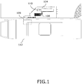
- FIG. 1 is a top view of a site where LNG is transferred from a first container 104 to a second container 106 with a system for transfer of LNG.
- the first container is preferably a cryogenic LNG-ISO container.
- the first container has arrived by truck and is positioned on a semitrailer, i.e. a trailer without a front axle, and is positioned in an enclosed area close to a pump station 108.
- the motored vehicle embodied as a truck 110, which is positioned the first container next to the pump station is still on site. At least for some sites, the truck may leave the site and return again when the first container is empty and to replace the empty container with a filled one.
- the second container 106 is included in a LNG powered ship 112, but could as well be a container in a truck or a container for a truck or for a ship.
- the LNG-ISO container (first container) is preferably and as illustrated positioned within a fencing assuring that the container is safeguarded against impact by other vehicles or similar and that the container is positioned at a given position relatively to the pump station. Further, the LNG-ISO container is preferably positioned on a platform, which platform is vaguely angled for the LNG to flow towards a connection for transfer of liquid natural gas out of the container. Hereby also a flow of LNG at least partly by gravity can be provided.
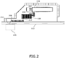
- a first thermally insulated pipe or hose 202 is shown leading from the first container to the pump station 108.
- the first thermally insulated pipe or hose 202 is a flexible hose.
- the first thermally insulated pipe or hose 202 has a first end 204 operably connected to the first container 104 and a second end 206 operably connected to the pump station 108 at an inlet side of the pump station.
- a second thermally insulated pipe or hose 208 with its first end 210 operably connected to the pump station and its second end 212 operably connected to the second container leads from the pump station 108 to the second container 106 on-board the ship 112.
- both the first and second containers are themselves thermally insulated, among others to reduce an amount of energy being transferred from the ambient conditions to inside the containers.
- Such insulation will not keep LNG cold enough by itself.
- Ambient heat will warm and vaporize the LNG, at least to some extent and depending on various factors such as time.
- the LNG is stored at its boiling point for the pressure at which it is stored.
- the LNG is stored at approximately standard atmospheric pressure.
- At least the first container is preferably including such system for maintaining a certain temperature of the stored LNG.
- FIG. 3 is a simplified and explanatory piping and instrumentation diagram (P&ID) of the system for transfer of LNG according to an embodiment of the invention.
- the simplified P&ID illustrates a system adapted for transferring liquid natural gas from the first container 104 to the second container 106 via the pump station 108.
- the pump station is provided in a 20' container, but may alternatively be provided in an 8' or 10' container or possibly in any other easily moveable container unit.
- first container 104 is positioned next to the pump station 108 by the motor driven vehicle and the second container 106 is positioned next to the pump station 108 on the ship 112.
- a minimum of distance is provided between the first container and the pump station and between the second container and the pump station, among others to reduce an amount of LNG in the thermally insulated hoses leading LNG from the first to the second container.
- Transfer of liquid natural gas from the first container 104 to the pump station 108 is provided via the first thermally insulated pipe or hose 202 connected at the first end 204 with a first dry coupling 304 to the first container 104, or to a first connection 312 leading to the first container, and connected at the second end 206 to the pump station.
- the transfer also includes transferring the liquid natural gas from the pump station and into the second container 106 by a pump 306 in the pump station and via a second thermally insulated pipe or hose 208 connected at its first end 210 to the pump station and connected at its second end 212 with a second dry coupling 308 to the second container 106, or to a second connection 310, as illustrated, leading to the second container.
- the second dry coupling 308 is disconnected at the second container or disconnected from the second connection 310, leading to the second container and there is provided a flow of liquid natural gas back into the first container.
- the flow of liquid natural gas back into the first container 104 is initiated after transfer of liquid natural gas to the second container and preferably after transfer has been stopped for a period of time.
- the flow back into the first container 104 is provided utilising an overpressure in the insulated pipes or hoses 202, 208 and in pipes of the pump station.
- the pressure can be considered an overpressure relatively to the pressure in the first container.
- the second container 106 can be filled a plurality of times with liquid natural gas from the first container 104 by repeating the process described and replacing the first container 104 with a filled first container when the first container is empty. Instead of repeatedly filling the same container 106, a plurality of different second containers may be filled with the system and method as described herein.
- a pressure difference between pipes etc. of the pumping station and the first container is preferably selected in the interval 50-700 kPa, more preferably between 200-600kPa, most preferred about 350-500 kPa.
- a difference of about 350-500 has e.g. been found to give the best trade-off between pipe dimensions, filling time (filling rate) and a time needed for the flow back into the first container.
- a pressure difference of e.g. about 350-500 kPa proper pipe dimensions, proper hose lengths etc.
- a time needed for the flow back of LNG is below 15 seconds, typically below 10 seconds, such as between 2-5 seconds.
- the pump station includes a fuel cell 314 for converting at least part of any remaining fluid of the natural gas in the insulated pipes or hoses 202, 208 and in pipes of the pump station, after transfer of liquid natural gas from the first container to the second container into electricity.
- This energy can be used for at least partly powering the pump station 108 or parts of the pump station, such as a control system 316 of the pump station.
- the converting device can alternatively or additionally be used to convert at least part of any overpressure building up in the pump station and/or hoses due to any remaining LNG, if any is present, boiling off and becoming gas.
- the system comprises a safe height vent 318 which can be used for venting overpressure anywhere in the system.
- Only one safety valve 328 is shown, but it is to be understood that in order to include this function a plurality of safety valves and connection are to be provided.
- LNG is not flammable or explosive in its liquid state.
- LNG vapours (its natural gas form) are only flammable within a limited range of concentration in the air. If the concentration of natural gas in the air is lower than 5% it cannot burn because of insufficient fuel. If the concentration of natural gas in the air is higher than 15% it cannot burn because there is insufficient oxygen.
- the fire hazard of LNG is preconditioned on the LNG being released, the LNG vaporizing, mixing with air in a very narrow gas to air ratio of 5-15% and finally finding an ignition source. LNG vapor will only explode if in an enclosed space and if within the flammable range of 5%-15% when mixed with air, and if ignited.
- the pressure and the flows are controlled by the control system 316, valves etc. and e.g. balanced and/or stabilized by venting NG via the safe valve(s) 328 and/or converting NG to another form of energy.
- the pressure in the pipes of the pumping station 108 will preferably be around 500-900 kPa, more preferably around 700 kPa. This is also controlled in dependence of, among others, the pressure in the second container, which can be around 400 kPa when using these pressures in the pump station.
- At least the pump 306 can be precooled prior to filling the second container 106 by recirculating liquid natural gas from the first container 104 through the pump 306 and back into the first container 104. This is provided via a recirculation flow path including a recirculation pipe or hose 307 leading from the pump station to the first container.
- the system also includes break away couplings 305, 309 for preventing leakage in case of unforeseen moving of the first and/or the second container prior to disconnecting the dry couplings.
- the system further includes manual valves 324 as well as automatic valves 322 for controlling the flow.
- the N 2 battery 320 is only for use when servicing the system.
- At least the second dry coupling 308 can be positioned at a level so that remaining LNG, if any remaining LNG is present in connections, pipes or hoses leading to the dry coupling is at least partly helped getting away from the dry coupling by gravity, and particularly prior to disconnecting the male and female parts of the dry coupling.
- the dry coupling will easier be or remain dry, e.g. when disconnecting the coupling.
- the second dry coupling 308 can be positioned so that LNG in the pipe or hose 208 is helped by gravity to return to the pump station 108, and so that LNG in the second connection 310 is helped by gravity to flow away from the dry coupling and towards the second container 106.
- FIG. 4 is a simplified and explanatory P&ID showing a recirculation path including the path 402 in the pump station. Using this recirculation/cooling path enables precooling at least the pump 306 prior to filling the second container 106 by recirculating liquid natural gas from the first container 104 through the pump 306 and back into the first container.
- FIG. 5 is a simplified and explanatory P&ID also showing inlet side hoses parking positions 502 in addition to the outlet side parking position 504.
- Such position of inlet and/or outlet hoses can e.g. be used when no first container is present and/or during service of the system. Alternatively and/or additionally such positions can be used when converting NG in the system into another form of energy.
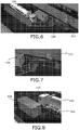
- FIGs 6-8 are perspective views of the system for transfer of LNG.
- liquid natural gas (LNG) transfer system in order to provide improved efficiency, e.g. in terms of how to operate and maintain a liquid natural gas (LNG) transfer system, while also improving the environmental friendliness of the transfer operation, there is disclosed a method and system of transferring liquid natural gas from a first container 104 to a second container 106 via a pump station 108.
- the first container 104 is positioned close to the pump station 108 by a truck 110
- the second container 106 is positioned close to the pump station 108 by a ship 112.
- first and second dry couplings 304, 308 Repeated transfer of LNG is provided using first and second dry couplings 304, 308 and, after transfer is complete, disconnecting the second dry coupling 308 from the second container and providing a flow of liquid natural gas back into the first container utilising an overpressure in the insulated pipes or hoses 202, 208 and in pipes of the pump station relatively to the pressure in the first container and by replacing the first container 104 with a filled first container when the first container is empty.
Landscapes
- Engineering & Computer Science (AREA)
- Mechanical Engineering (AREA)
- General Engineering & Computer Science (AREA)
- Chemical & Material Sciences (AREA)
- Combustion & Propulsion (AREA)
- Ocean & Marine Engineering (AREA)
- Filling Or Discharging Of Gas Storage Vessels (AREA)
Description
- The invention relates to transfer of natural gas, which has been liquefied to become liquid natural gas (LNG) or liquefied natural gas (LNG), from a first to a second container. The invention is in an embodiment explained in connection with transfer of LNG to a second container positioned in a LNG powered vessel, ship or ferry, such as for a ferry route.
- Natural gas boils at a temperature of about minus 160°C - minus 164°C when under a pressure close to normal atmospheric pressure (about 101.3kPa at sea level), mainly depending on the amount of methane in the gas, of which natural gas typically contains 80-95%.
- In order to provide an efficient, also in terms of cost, storage or transport of natural gas, the gas is liquefied into liquid state, LNG. LNG typically takes up about 0.15-0.2% of the volume of natural gas in gaseous state. LNG is typically transported in cryogenic, insulated containers by road or sea.
- As also explained in
EP2212186 , marine vessels can be fuelled by LNG. Also with LNG, marine vessels need to be refuelled, also called bunkered, at certain intervals. Bunkering operation usually takes place in port, but may also take place at other locations, such as at a floating bunkering facility out at sea. - Bunkering operation of a LNG fuelled marine vessel may take a long time. A reason for this is the temperature difference between LNG (normally stored at about -162°C) and the bunkering line (normally in ambient temperature, around - 10°C to +25°C for northern Europe). This temperature difference causes at least a part of the LNG to boil in the bunkering line, which leads to a two-phase flow of gas and liquid. The two-phase flow may cause control problems and pressure pulses, which may be harmful for the supply procedure and for the piping arrangements of the bunkering system.
- Consequently, in order to arrive at a functioning bunkering operation, LNG flow rate may have to be kept low in the beginning of the operation in order to minimize, or at least in an attempt to keep the pressure pulses at an acceptable level. After the bunkering line starts to cool down, the flow rate may slowly be increased. A typical practice and trend in marine vessel operation of today is shortened port times and increased operating speeds, which leads to a transfer of larger amounts of fuel in a shorter time.
-
DE20115995 relates to an apparatus for transferring liquid air or liquid nitrogen with the lowest amount of loss, e.g. by use of an insulated transfer hose.DE20115995 addresses the problem of proposing ways to pass liquid air or liquid nitrogen with minimum losses and in large quantities to a consumer, for example a vehicle. To achieve this object, there is provided that the liquid air or liquid nitrogen, in a housing contained in the transfer station pumping station, is guided to an insulated storage tank located upstream of the transfer station. - These and other factors influence a short and/or long term efficiency, e.g. in terms of how to operate and maintain the transfer system, but also influences an environmental friendliness of the transfer (or bunkering) operation. Hence, the inventors of the present invention have appreciated that an improved method and system for transfer of liquid natural gas is of benefit, and have in consequence devised the present invention.
- It may be seen as an object of the present invention to provide an improved method and system for transfer of liquid natural gas from a first to a second container. Preferably, the invention alleviates, mitigates or eliminates one or more of the above or other disadvantages singly or in any combination.
- In particular, it may be seen as an object of the invention to provide a method of transferring liquid natural gas from a first container to a second container, which method provides improved short and long term efficiency, in terms of how to operate and maintain the system, while also improving the environmental friendliness of the transfer operation, when compared to known methods and systems.
- Accordingly, in a first aspect, there is provided, a method of transferring liquid natural gas from a first container to a second container via a pump station, the method comprising
- a) positioning the first container close to, such as less than 25 meter from, the pump station by a motor driven vehicle, such as a truck,
- b) positioning the second container close to, such as less than 25 meter from, the pump station by a mobile unit, such as a truck or a ship,
- c) transferring the liquid natural gas from the first container to the pump station via a first thermally insulated pipe or hose connected at a first end with a first dry coupling to the first container, or to a first connection leading to the first container, and connected at a second end to the pump station,
- d) transferring the liquid natural gas from the pump station and into the second container by a pump in the pump station and via a second thermally insulated pipe or hose connected at a first end to the pump station and connected at a second end with a second dry coupling to the second container, or to a second connection leading to the second container, and, after transfer is complete,
- e) disconnecting the second dry coupling at the second container or disconnecting it from the second connection leading to the second container and providing a flow of liquid natural gas back into the first container including utilising an overpressure in the insulated pipes or hoses and in pipes of the pump station relatively to the pressure in the first container to provide said flow, and
- f) filling the second container a plurality of times with liquid natural gas from the first container and/or filling a plurality of different second containers with liquid natural gas from the first container by repeating method steps b) - e),
- g) replacing the first container with a filled first container by performing method step a) when the first container is empty.
- Thus, an improved method of transferring liquid natural gas from a first to a second container is provided.
- The present method utilises a pump for transfer of the liquid natural gas (LNG) to the second container. The pump is positioned apart from the first and second containers in a pump station. Further, the first container containing bulk LNG for transfer of the LNG to the second container is of a kind which, when filled with LNG, can easily be positioned at the pump station as described herein and by a motor driven vehicle.
- In short, these features (of method steps a) and b)) distinguishes the present invention over at least some of the prior art and provides for a method and system which does not, as examples, require a crane for moving a filled container, as likely needed in
WO2011124748 , or a (large, non-moveable) fixed container at the bunkering site to be filled and refilled for later transfer of LNG to a further container and does also not require an extensive filling time to pass for transferring a certain amount of gas, among others due to the use of a pump station. - Further, it is found that the method distinguishes over the prior art when also including method steps c) and d) as described. Here, a dry coupling is to include a coupling including a male part and a female part, which male and female parts are each closed when they are not connected to each other, and where flow through the coupling is only possible when they are connected together. Further, and for the present purpose, effectively no volume at all is present between male and female parts when or if connected. The male and female parts are typically provided as one part on each of the two connections to be connected.
- The conjunction of those method steps with method step e) along with repeated filling of second containers in f) and replacing of the first container in step g) may be seen to provide improved short and long term efficiency of the method and system, in terms of how to operate and maintain the system, while also improving the environmental friendliness of the transfer operation.
- Particularly, and with the method and system described herein, it is also prevented to purge the system with, e.g., nitrogen as described in
EP2212186 section [0035], in order to clean various parts of the system between separate filling cycles, which nitrogen will then itself (as an insight by the present inventors) have to be cleaned out of the system with NG or LNG, which purging and following cleaning out the nitrogen process takes time and results in rather extensive use of nitrogen and typically also results in release of both nitrogen and NG to the atmosphere, at least in the process of cleaning out the nitrogen used to clean out the LNG. - If not cleaning out the nitrogen, it is an insight of the present inventors that such nitrogen at least partly hinders an efficient subsequent transfer process and/or a short term and/or long term effectiveness of the LNG powered motor, system or similar using the LNG transferred to the second container, but the present inventors have devised an effective method and system without using nitrogen for such purging purposes. Nitrogen may be used during certain maintenance procedures of the system, but is not needed between filling cycles.
- When including the optional features of initiating the flow of liquid natural gas back into the first container after transfer of liquid natural gas to the second container has been stopped for a period of time, this provides for an ability to have fast filling cycles without a flow back into the first container, which may be particularly useful when the method and system is used for transfer of LNG to second containers for or in a LNG powered truck. For such purpose the containers may arrive or be conveyed to the pump station at a rate where immediate flow back of LNG into the first container can be considered inefficient. The period of time may be selected to be such as 30 seconds, 45 seconds, 60 seconds, 2, 3, 4 or 5 minutes, but unlikely longer except for when extensive insulation can be provided for piping in the pump station, hoses etc. and/or under extreme cold ambient conditions.
- Even though the method describes a flow back of LNG to the first container, an amount (likely minor and among others dependent on the various pressures and temperatures, dimension and length of the hoses etc.) of LNG and/or mixture of LNG and NG may remain in the hoses and in pipes of the pump station. When utilising at least part or all of such remaining fluid of the natural gas in the insulated pipes or hoses and in the pump station, after transfer of the liquid natural gas from the first container to the second container, for cooling parts of the pump station or hoses for that matter, rather fast filling cycles can particularly be performed with improved efficiency. Such rather fast filling cycles may be filling a container every 30 seconds, every minute, every 5 minutes, every 10 minutes, every 15 minutes or every 30 or 60 minutes.
- As an alternative to venting NG to the atmosphere, which is found unwanted, at least part of or all of any remaining fluid, if any is there, of the natural gas in the first and/or second insulated pipes or hoses and in the (pipes of the) pump station can be converted into another form of energy by a converting device. Hereby a source of energy, such as for at least partly powering the pump station, such as at least partly powering a control system of the pump station, is provided. The converting device may comprise a fuel cell converting the fluid into electricity.
- By converting any remaining fluid, if any, into another form of energy, a method and system is provided which also enables prevention of release of NG into the atmosphere and which does also not need use of nitrogen as explained above.
- At least in order to provide a safe vent to a safe height and e.g. to prevent pressures above a certain threshold in the pump station, at least part of remaining natural gas in the insulated pipes or hoses and in (the pipes of and/or in the pump of) the pump station may be vented to the atmosphere via one or more safety valves and to the safe height vent. The pressure threshold can be selected such as to be 800 kPa, 1000 kPa, 1200 or 1500 kPa.
- In accordance with an embodiment at least the pump is precooled prior to filling the second container by recirculating liquid natural gas from the first container through the pump and back into the first container via a recirculation flow path. Hereby increased flow rates can be accomplished afterwards, especially for systems and pumps working at best with such precooling. In such method and system a recirculation flow path is provided between the pump station and the first container. Further, in at least one way of providing such recirculation path (see
figure 4 ), the recirculation path may be used to recirculate LNG being forwarded by the pump in the pumping station, e.g. in case of unforeseen circumstances such as sudden closing of a safety valve in, or in connection with, the pump station or a safety valve closing in a device, such as a ship, where the second container is placed or to be placed. This may particularly and as an example be of use in a system where the pump is rather slow reacting to such unforeseen circumstances and thus e.g. to prevent improper pressure build up in the hoses or pump station. - In accordance with a second aspect of the invention there is provided a system for transfer of liquid natural gas and adapted to perform the method in accordance with the method as described.
- According to a particular embodiment of such system, the pump station is provided as a separate unit, such as in a container, and the pump is included in this container. By incorporating the pump and various other equipment, such as valves etc. in the container, a separate pump station is provided as a mobile unit which is easy moveable.
- According to preferred embodiments, the system and method as described herein is used for transferring liquid natural gas to a second container, the second container being intended for a liquid natural gas powered ship or the second container being provided in a liquid natural gas powered ship, such as a ferry, or for transferring liquid natural gas to a second container for or in an liquid natural gas powered vehicle. For such use, a cyclic refilling of the container in the LNG powered means of transportation occurs, which refilling is found in need of improvement, and thus the present invention has been devised.
- By referring to an advantage herein, it must be understood that this advantage may be seen as a possible advantage provided by the invention, but it may also be understood that the invention is particularly, but not exclusively, advantageous for obtaining the described advantage.
- Embodiments of the invention will be described, by way of example only, with reference to the drawings, in which
-
FIG. 1 is a top view of a site where LNG is transferred from a first to a second container with a system for transfer of LNG, -
FIG. 2 is a close up view offigure 1 , -
FIG. 3 is a simplified and explanatory piping and instrumentation diagram (P&ID) of the system for transfer of LNG, -
FIG. 4 is a simplified and explanatory P&ID showing a recirculation path including an internal path, -
FIG. 5 is a simplified and explanatory P&ID showing inlet side hoses parking positions, and -
FIGs 6-8 are perspective views of the system for transfer of LNG. - List of reference numbers with description (the first number refer to the figure number in which the reference was shown/described firstly):
- 104
- First container
- 106
- Second container
- 108
- Pump station
- 110
- Truck for delivering first container
- 112
- LNG powered ship
- 202
- First thermally insulated pipe or hose
- 204
- First end of 202
- 206
- Second end of 202
- 208
- Second thermally insulated pipe or hose
- 210
- First end of 208
- 212
- Second end of 208
- 302
- System for transfer of LNG
- 304
- First dry coupling
- 305
- First break away coupling
- 306
- Pump
- 307
- Recirculation pipe or hose
- 308
- Second dry coupling
- 309
- Second break away coupling
- 310
- Second connection leading to second container
- 312
- First connection leading to first container
- 314
- Fuel cell
- 316
- Control system for pump station
- 318
- Safe height vent
- 320
- N2 battery (for service)
- 322
- Automatic valve
- 324
- Manual valve
- 326
- Strainer/filter
- 328
- Safety valve
- 402
- Recirculation path including internal path
- 502
- Parking positions inlet side
- 504
- Parking position for 2nd thermally insulated pipe or hose (outlet side)
-
FIG. 1 is a top view of a site where LNG is transferred from afirst container 104 to asecond container 106 with a system for transfer of LNG. The first container is preferably a cryogenic LNG-ISO container. In the embodiment, the first container has arrived by truck and is positioned on a semitrailer, i.e. a trailer without a front axle, and is positioned in an enclosed area close to apump station 108. In the shown embodiment the motored vehicle, embodied as atruck 110, which is positioned the first container next to the pump station is still on site. At least for some sites, the truck may leave the site and return again when the first container is empty and to replace the empty container with a filled one. In the shown embodiment, thesecond container 106 is included in a LNG poweredship 112, but could as well be a container in a truck or a container for a truck or for a ship. - The LNG-ISO container (first container) is preferably and as illustrated positioned within a fencing assuring that the container is safeguarded against impact by other vehicles or similar and that the container is positioned at a given position relatively to the pump station. Further, the LNG-ISO container is preferably positioned on a platform, which platform is vaguely angled for the LNG to flow towards a connection for transfer of liquid natural gas out of the container. Hereby also a flow of LNG at least partly by gravity can be provided.
- In the close up of
FIG. 2 , a first thermally insulated pipe orhose 202 is shown leading from the first container to thepump station 108. In the embodiment the first thermally insulated pipe orhose 202 is a flexible hose. The first thermally insulated pipe orhose 202 has afirst end 204 operably connected to thefirst container 104 and asecond end 206 operably connected to thepump station 108 at an inlet side of the pump station. It also follows that a second thermally insulated pipe orhose 208 with itsfirst end 210 operably connected to the pump station and itssecond end 212 operably connected to the second container leads from thepump station 108 to thesecond container 106 on-board theship 112. - Preferably and typically, both the first and second containers are themselves thermally insulated, among others to reduce an amount of energy being transferred from the ambient conditions to inside the containers. Such insulation, as efficient as it is, will not keep LNG cold enough by itself. Ambient heat will warm and vaporize the LNG, at least to some extent and depending on various factors such as time. It is practice to store LNG as a boiling cryogen. The LNG is stored at its boiling point for the pressure at which it is stored. Herein, and for the first container, the LNG is stored at approximately standard atmospheric pressure.
- As the vapour boils off, heat for the phase change cools the remaining liquid. Because the insulation is very efficient, only a relatively small amount of boil off is necessary to maintain temperature in this so called auto-refrigeration process. At least the first container is preferably including such system for maintaining a certain temperature of the stored LNG.
-
FIG. 3 is a simplified and explanatory piping and instrumentation diagram (P&ID) of the system for transfer of LNG according to an embodiment of the invention. The simplified P&ID illustrates a system adapted for transferring liquid natural gas from thefirst container 104 to thesecond container 106 via thepump station 108. The pump station is provided in a 20' container, but may alternatively be provided in an 8' or 10' container or possibly in any other easily moveable container unit. - As seen the
first container 104 is positioned next to thepump station 108 by the motor driven vehicle and thesecond container 106 is positioned next to thepump station 108 on theship 112. Preferably, a minimum of distance is provided between the first container and the pump station and between the second container and the pump station, among others to reduce an amount of LNG in the thermally insulated hoses leading LNG from the first to the second container. - Transfer of liquid natural gas from the
first container 104 to thepump station 108 is provided via the first thermally insulated pipe orhose 202 connected at thefirst end 204 with a firstdry coupling 304 to thefirst container 104, or to afirst connection 312 leading to the first container, and connected at thesecond end 206 to the pump station. The transfer also includes transferring the liquid natural gas from the pump station and into thesecond container 106 by apump 306 in the pump station and via a second thermally insulated pipe orhose 208 connected at itsfirst end 210 to the pump station and connected at itssecond end 212 with a seconddry coupling 308 to thesecond container 106, or to asecond connection 310, as illustrated, leading to the second container. - After transfer is complete, the second
dry coupling 308 is disconnected at the second container or disconnected from thesecond connection 310, leading to the second container and there is provided a flow of liquid natural gas back into the first container. The flow of liquid natural gas back into thefirst container 104 is initiated after transfer of liquid natural gas to the second container and preferably after transfer has been stopped for a period of time. - The flow back into the
first container 104 is provided utilising an overpressure in the insulated pipes orhoses second container 106 can be filled a plurality of times with liquid natural gas from thefirst container 104 by repeating the process described and replacing thefirst container 104 with a filled first container when the first container is empty. Instead of repeatedly filling thesame container 106, a plurality of different second containers may be filled with the system and method as described herein. - A pressure difference between pipes etc. of the pumping station and the first container is preferably selected in the interval 50-700 kPa, more preferably between 200-600kPa, most preferred about 350-500 kPa. A difference of about 350-500 has e.g. been found to give the best trade-off between pipe dimensions, filling time (filling rate) and a time needed for the flow back into the first container. With a pressure difference of e.g. about 350-500 kPa, proper pipe dimensions, proper hose lengths etc., a time needed for the flow back of LNG is below 15 seconds, typically below 10 seconds, such as between 2-5 seconds.
- The pump station includes a
fuel cell 314 for converting at least part of any remaining fluid of the natural gas in the insulated pipes orhoses pump station 108 or parts of the pump station, such as acontrol system 316 of the pump station. The converting device can alternatively or additionally be used to convert at least part of any overpressure building up in the pump station and/or hoses due to any remaining LNG, if any is present, boiling off and becoming gas. - Among others as a safety measure the system comprises a
safe height vent 318 which can be used for venting overpressure anywhere in the system. Only onesafety valve 328 is shown, but it is to be understood that in order to include this function a plurality of safety valves and connection are to be provided. Here it is noted that LNG is not flammable or explosive in its liquid state. LNG vapours (its natural gas form) are only flammable within a limited range of concentration in the air. If the concentration of natural gas in the air is lower than 5% it cannot burn because of insufficient fuel. If the concentration of natural gas in the air is higher than 15% it cannot burn because there is insufficient oxygen. Therefore, the fire hazard of LNG is preconditioned on the LNG being released, the LNG vaporizing, mixing with air in a very narrow gas to air ratio of 5-15% and finally finding an ignition source. LNG vapor will only explode if in an enclosed space and if within the flammable range of 5%-15% when mixed with air, and if ignited. - In the
pump station 108, e.g., the pressure and the flows are controlled by thecontrol system 316, valves etc. and e.g. balanced and/or stabilized by venting NG via the safe valve(s) 328 and/or converting NG to another form of energy. During and just after pumping LNG from the first 104 to thesecond container 106, the pressure in the pipes of the pumpingstation 108 will preferably be around 500-900 kPa, more preferably around 700 kPa. This is also controlled in dependence of, among others, the pressure in the second container, which can be around 400 kPa when using these pressures in the pump station. - At least the
pump 306 can be precooled prior to filling thesecond container 106 by recirculating liquid natural gas from thefirst container 104 through thepump 306 and back into thefirst container 104. This is provided via a recirculation flow path including a recirculation pipe orhose 307 leading from the pump station to the first container. - As illustrated, the system also includes break away
couplings manual valves 324 as well asautomatic valves 322 for controlling the flow. The N2 battery 320 is only for use when servicing the system. - According to possible embodiments of the invention, at least the second
dry coupling 308 can be positioned at a level so that remaining LNG, if any remaining LNG is present in connections, pipes or hoses leading to the dry coupling is at least partly helped getting away from the dry coupling by gravity, and particularly prior to disconnecting the male and female parts of the dry coupling. Hereby, the dry coupling will easier be or remain dry, e.g. when disconnecting the coupling. As an example, the seconddry coupling 308 can be positioned so that LNG in the pipe orhose 208 is helped by gravity to return to thepump station 108, and so that LNG in thesecond connection 310 is helped by gravity to flow away from the dry coupling and towards thesecond container 106. -
FIG. 4 is a simplified and explanatory P&ID showing a recirculation path including thepath 402 in the pump station. Using this recirculation/cooling path enables precooling at least thepump 306 prior to filling thesecond container 106 by recirculating liquid natural gas from thefirst container 104 through thepump 306 and back into the first container. -
FIG. 5 is a simplified and explanatory P&ID also showing inlet sidehoses parking positions 502 in addition to the outletside parking position 504. Such position of inlet and/or outlet hoses can e.g. be used when no first container is present and/or during service of the system. Alternatively and/or additionally such positions can be used when converting NG in the system into another form of energy. -
FIGs 6-8 are perspective views of the system for transfer of LNG. - In short it is herein disclosed that in order to provide improved efficiency, e.g. in terms of how to operate and maintain a liquid natural gas (LNG) transfer system, while also improving the environmental friendliness of the transfer operation, there is disclosed a method and system of transferring liquid natural gas from a
first container 104 to asecond container 106 via apump station 108. Thefirst container 104 is positioned close to thepump station 108 by atruck 110, and thesecond container 106 is positioned close to thepump station 108 by aship 112. Repeated transfer of LNG is provided using first and seconddry couplings dry coupling 308 from the second container and providing a flow of liquid natural gas back into the first container utilising an overpressure in the insulated pipes orhoses first container 104 with a filled first container when the first container is empty. - Although the present invention has been described in connection with preferred embodiments, it is not intended to be limited to the specific form set forth herein. Rather, the scope of the present invention is limited only by the accompanying claims.
- For the purposes of brevity and clarity, detailed descriptions of well-known apparatus, circuits and methodology have been omitted so as to avoid unnecessary detail and possible confusion.
- In the claims, the term "comprising" does not exclude the presence of other elements or steps. Additionally, although individual features may be included in different claims, these may possibly be advantageously combined, and the inclusion in different claims does not imply that a combination of features is not feasible and/or advantageous. In addition, singular references do not exclude a plurality. Thus, references to "a", "an", "first", "second" etc. do not preclude a plurality. Reference signs are included in the claims however the inclusion of the reference signs is only for clarity reasons and should not be construed as limiting the scope of the claims.
Claims (8)
- A method of transferring liquid natural gas from a first container (104) to a second container (106) for a liquid natural gas powered vehicle or marine vessel via a pump station (108), the method comprisinga) positioning the first container (104) close to, the pump station (108) by a motor driven vehicle,b) positioning the second container (106) close to, such as less than 25 meter from, the pump station (108) by a mobile unit,c) transferring the liquid natural gas from the first container (104) to the pump station (108) via a first thermally insulated pipe or hose (202) connected at a first end (204) with a first dry coupling (304) to the first container (104), or to a first connection (312) leading to the first container, and connected at a second end (206) to the pump station,d) transferring the liquid natural gas from the pump station and into the second container (106) by a pump (306) in the pump station and via a second thermally insulated pipe or hose (208) connected at a first end (210) to the pump station and connected at a second end (212) with a second dry coupling (308) to the second container (106), or to a second connection (310) leading to the second container, and, after transfer is complete,e) disconnecting the second dry coupling (308) at the second container or disconnecting it from the second connection (310) leading to the second container and providing a flow of liquid natural gas back into the first container including utilising an overpressure in the insulated pipes or hoses (202, 208) and in pipes of the pump station relatively to the pressure in the first container to provide said flow, andf) filling the second container (106) a plurality of times with liquid natural gas from the first container (104) or filling a plurality of different second containers with liquid natural gas from the first container by repeating method steps b) - e),g) replacing the first container (104) with a filled first container by performing method step a) when the first container is empty.
- The method according to claim 1, further comprising utilising at least part of any remaining fluid of natural gas in the insulated pipes or hoses (202, 208) and in pipes of the pump station (108), after transfer of liquid natural gas from the first container (104) to the second container (106), for cooling parts of the pump station.
- The method according to any of the preceding claims, further comprising converting at least part of any remaining fluid of the natural gas in the insulated pipes or hoses (202, 208) and in pipes of the pump station, after transfer of liquid natural gas from the first container to the second container, into another form of energy by a converting device.
- The method according to claim 3, where said remaining fluid is converted into electricity by the converting device.
- The method according to claim 4, where the converting device comprises a fuel cell (314).
- The method according to any of the claims 3-5, where the energy is used for at least partly powering the pump station (108) or parts of the pump station, such as a control system (316) of the pump station.
- The method according to any of the preceding claims, further comprising venting at least part of any remaining natural gas in the insulated pipes or hoses (202, 208) and in pipes of the pump station to the atmosphere via a safe height vent (318).
- The method according to any of the preceding claims, further comprising precooling at least the pump (306) prior to filling the second container (106) by recirculating liquid natral gas from the first container (104) through the pump (306) and back into the first container (104) via a recirculation flow path (402, 307).
Applications Claiming Priority (2)
| Application Number | Priority Date | Filing Date | Title |
|---|---|---|---|
| DKPA201370790A DK178151B1 (en) | 2013-12-19 | 2013-12-19 | Liquid Natural Gas transfer |
| PCT/DK2014/050427 WO2015090327A2 (en) | 2013-12-19 | 2014-12-12 | Liquid natural gas transfer |
Publications (2)
| Publication Number | Publication Date |
|---|---|
| EP3084286A2 EP3084286A2 (en) | 2016-10-26 |
| EP3084286B1 true EP3084286B1 (en) | 2018-10-03 |
Family
ID=52103190
Family Applications (1)
| Application Number | Title | Priority Date | Filing Date |
|---|---|---|---|
| EP14812863.0A Active EP3084286B1 (en) | 2013-12-19 | 2014-12-12 | Liquid natural gas transfer |
Country Status (8)
| Country | Link |
|---|---|
| US (1) | US20160281927A1 (en) |
| EP (1) | EP3084286B1 (en) |
| KR (1) | KR102259492B1 (en) |
| CA (1) | CA2928566C (en) |
| DK (1) | DK178151B1 (en) |
| ES (1) | ES2701248T3 (en) |
| MY (1) | MY184258A (en) |
| WO (1) | WO2015090327A2 (en) |
Families Citing this family (6)
| Publication number | Priority date | Publication date | Assignee | Title |
|---|---|---|---|---|
| EP3431860A1 (en) * | 2017-07-21 | 2019-01-23 | Cryostar SAS | Method for transferring a cryogenic fluid and transfer system for implementing such a method |
| ES2724565B2 (en) * | 2018-03-06 | 2020-09-10 | Naturgy Lng S L | TANK CARRIER FOR REFUELING VESSELS PROPELLED BY LIQUEFIED NATURAL GAS (LNG), AS WELL AS LIQUEFIED NATURAL GAS LOADING STATION |
| US20210275961A1 (en) * | 2018-07-10 | 2021-09-09 | Iogen Corporation | Method and system for upgrading biogas |
| CA3145848A1 (en) | 2019-07-09 | 2021-01-14 | Iogen Corporation | Method and system for producing a fuel from biogas |
| FR3113310B1 (en) * | 2020-08-05 | 2022-07-15 | Air Liquide | Device and method for filling liquefied gas |
| KR102264415B1 (en) * | 2020-11-25 | 2021-06-14 | 대흥산업가스 주식회사 | Simple LNG charging station that guarantees excellent safety and mobility |
Family Cites Families (15)
| Publication number | Priority date | Publication date | Assignee | Title |
|---|---|---|---|---|
| US3962882A (en) * | 1974-09-11 | 1976-06-15 | Shell Oil Company | Method and apparatus for transfer of liquefied gas |
| US5954101A (en) * | 1996-06-14 | 1999-09-21 | Mve, Inc. | Mobile delivery and storage system for cryogenic fluids |
| DE10010193A1 (en) * | 2000-03-02 | 2001-09-20 | Messer Italia S P A | Filler of liquid gas into container, has conveyor, storage tank, gas discharge pipe, pump stages, and flow connection |
| AT4883U1 (en) * | 2000-06-23 | 2001-12-27 | Hermeling Werner Dipl Ing | MOBILE FILLING SYSTEM FOR GAS BOTTLES |
| US6640554B2 (en) * | 2001-04-26 | 2003-11-04 | Chart Inc. | Containment module for transportable liquid natural gas dispensing station |
| DE20115995U1 (en) * | 2001-09-28 | 2001-12-06 | Schmid Heinrich | Transfer device for liquid air or nitrogen |
| FR2857432B1 (en) * | 2003-07-10 | 2005-09-23 | Air Liquide | SYSTEM FOR FILLING A CRYOGENIC FLUID RESERVOIR OF A MOBILE CISTERN |
| JP2005280973A (en) * | 2004-03-31 | 2005-10-13 | Chugoku Electric Power Co Inc:The | Method for controlling bulk container |
| CN1989369A (en) * | 2004-07-23 | 2007-06-27 | 索尔维公司 | Method for transferring a fluid |
| DE102004038460A1 (en) * | 2004-08-07 | 2006-03-16 | Messer France S.A. | Method and device for filling a container with liquid gas from a storage tank |
| AU2006241566B2 (en) * | 2005-05-04 | 2010-12-16 | Single Buoy Moorings Inc. | Large distance offshore LNG export terminal with boil-off vapour collection and utilization capacities |
| FR2908859B1 (en) * | 2006-11-22 | 2009-02-20 | Air Liquide | METHOD AND STATION FOR REFUELING IN HYDROGEN |
| FI122608B (en) * | 2007-11-12 | 2012-04-13 | Waertsilae Finland Oy | Procedure for operating a LNG-powered watercraft and a drive system for an LNG-powered watercraft |
| WO2010151107A1 (en) * | 2009-06-25 | 2010-12-29 | Ballast Nedam International Product Management B.V. | Device and method for the delivery of lng |
| US8375876B2 (en) * | 2010-12-04 | 2013-02-19 | Argent Marine Management, Inc. | System and method for containerized transport of liquids by marine vessel |
-
2013
- 2013-12-19 DK DKPA201370790A patent/DK178151B1/en active
-
2014
- 2014-12-12 ES ES14812863T patent/ES2701248T3/en active Active
- 2014-12-12 WO PCT/DK2014/050427 patent/WO2015090327A2/en active Application Filing
- 2014-12-12 EP EP14812863.0A patent/EP3084286B1/en active Active
- 2014-12-12 US US15/035,723 patent/US20160281927A1/en not_active Abandoned
- 2014-12-12 MY MYPI2016000946A patent/MY184258A/en unknown
- 2014-12-12 CA CA2928566A patent/CA2928566C/en active Active
- 2014-12-12 KR KR1020167019713A patent/KR102259492B1/en active IP Right Grant
Non-Patent Citations (1)
| Title |
|---|
| None * |
Also Published As
| Publication number | Publication date |
|---|---|
| KR20160117442A (en) | 2016-10-10 |
| DK178151B1 (en) | 2015-07-06 |
| ES2701248T3 (en) | 2019-02-21 |
| CA2928566C (en) | 2022-01-18 |
| EP3084286A2 (en) | 2016-10-26 |
| CA2928566A1 (en) | 2015-06-25 |
| DK201370790A1 (en) | 2015-06-29 |
| MY184258A (en) | 2021-03-29 |
| WO2015090327A2 (en) | 2015-06-25 |
| US20160281927A1 (en) | 2016-09-29 |
| WO2015090327A3 (en) | 2015-08-13 |
| KR102259492B1 (en) | 2021-06-04 |
Similar Documents
| Publication | Publication Date | Title |
|---|---|---|
| EP3084286B1 (en) | Liquid natural gas transfer | |
| EP3784952B1 (en) | Cryogenic fluid dispensing system having a chilling reservoir | |
| US5682750A (en) | Self-contained liquid natural gas filling station | |
| US6899146B2 (en) | Method and apparatus for dispensing compressed natural gas and liquified natural gas to natural gas powered vehicles | |
| US6360730B1 (en) | Inert loading jet fuel | |
| EP2989370B1 (en) | Liquid natural gas cooling on the fly | |
| US20080134693A1 (en) | Storage Tank For A Cryogenic Liquid And Method Of Re-Filling Same | |
| US10738944B2 (en) | System for draining and refilling cryogenic fuel in a vehicle tank | |
| CN110582632B (en) | Liquefied gas fuel feeding system and ship | |
| EP1490624B1 (en) | Storage tank for cryogenic liquids | |
| US11300248B2 (en) | Device and process for filling a mobile refrigerant tank with a cryogenic refrigerant | |
| US11353161B2 (en) | Module and system for depressurising a cryogenic tank | |
| US10094515B2 (en) | Non-venting transfer system and method | |
| CN111417818B (en) | Indoor safety device, liquefied gas system and vehicle | |
| JP2007009982A (en) | Gas feeding apparatus for liquefied gas | |
| JP2007009981A (en) | Liquefied gas feeding apparatus and liquefied gas feeding method | |
| JP2021507178A (en) | Methods and equipment for storing liquefied gas in a container and drawing evaporative gas out of the container | |
| KR101966200B1 (en) | System and Process for Liquefied Gas Filling | |
| Hettinger et al. | Refueling equipment for liquid hydrogen vehicles |
Legal Events
| Date | Code | Title | Description |
|---|---|---|---|
| PUAI | Public reference made under article 153(3) epc to a published international application that has entered the european phase |
Free format text: ORIGINAL CODE: 0009012 |
|
| 17P | Request for examination filed |
Effective date: 20160414 |
|
| AK | Designated contracting states |
Kind code of ref document: A2 Designated state(s): AL AT BE BG CH CY CZ DE DK EE ES FI FR GB GR HR HU IE IS IT LI LT LU LV MC MK MT NL NO PL PT RO RS SE SI SK SM TR |
|
| AX | Request for extension of the european patent |
Extension state: BA ME |
|
| DAX | Request for extension of the european patent (deleted) | ||
| GRAP | Despatch of communication of intention to grant a patent |
Free format text: ORIGINAL CODE: EPIDOSNIGR1 |
|
| INTG | Intention to grant announced |
Effective date: 20180424 |
|
| GRAS | Grant fee paid |
Free format text: ORIGINAL CODE: EPIDOSNIGR3 |
|
| GRAA | (expected) grant |
Free format text: ORIGINAL CODE: 0009210 |
|
| AK | Designated contracting states |
Kind code of ref document: B1 Designated state(s): AL AT BE BG CH CY CZ DE DK EE ES FI FR GB GR HR HU IE IS IT LI LT LU LV MC MK MT NL NO PL PT RO RS SE SI SK SM TR |
|
| REG | Reference to a national code |
Ref country code: GB Ref legal event code: FG4D |
|
| REG | Reference to a national code |
Ref country code: CH Ref legal event code: EP Ref country code: AT Ref legal event code: REF Ref document number: 1048996 Country of ref document: AT Kind code of ref document: T Effective date: 20181015 |
|
| REG | Reference to a national code |
Ref country code: DE Ref legal event code: R096 Ref document number: 602014033477 Country of ref document: DE Ref country code: IE Ref legal event code: FG4D |
|
| REG | Reference to a national code |
Ref country code: SE Ref legal event code: TRGR |
|
| REG | Reference to a national code |
Ref country code: NL Ref legal event code: MP Effective date: 20181003 |
|
| REG | Reference to a national code |
Ref country code: ES Ref legal event code: FG2A Ref document number: 2701248 Country of ref document: ES Kind code of ref document: T3 Effective date: 20190221 |
|
| REG | Reference to a national code |
Ref country code: LT Ref legal event code: MG4D |
|
| REG | Reference to a national code |
Ref country code: AT Ref legal event code: MK05 Ref document number: 1048996 Country of ref document: AT Kind code of ref document: T Effective date: 20181003 |
|
| PG25 | Lapsed in a contracting state [announced via postgrant information from national office to epo] |
Ref country code: NL Free format text: LAPSE BECAUSE OF FAILURE TO SUBMIT A TRANSLATION OF THE DESCRIPTION OR TO PAY THE FEE WITHIN THE PRESCRIBED TIME-LIMIT Effective date: 20181003 |
|
| PG25 | Lapsed in a contracting state [announced via postgrant information from national office to epo] |
Ref country code: LV Free format text: LAPSE BECAUSE OF FAILURE TO SUBMIT A TRANSLATION OF THE DESCRIPTION OR TO PAY THE FEE WITHIN THE PRESCRIBED TIME-LIMIT Effective date: 20181003 Ref country code: LT Free format text: LAPSE BECAUSE OF FAILURE TO SUBMIT A TRANSLATION OF THE DESCRIPTION OR TO PAY THE FEE WITHIN THE PRESCRIBED TIME-LIMIT Effective date: 20181003 Ref country code: NO Free format text: LAPSE BECAUSE OF FAILURE TO SUBMIT A TRANSLATION OF THE DESCRIPTION OR TO PAY THE FEE WITHIN THE PRESCRIBED TIME-LIMIT Effective date: 20190103 Ref country code: AT Free format text: LAPSE BECAUSE OF FAILURE TO SUBMIT A TRANSLATION OF THE DESCRIPTION OR TO PAY THE FEE WITHIN THE PRESCRIBED TIME-LIMIT Effective date: 20181003 Ref country code: IS Free format text: LAPSE BECAUSE OF FAILURE TO SUBMIT A TRANSLATION OF THE DESCRIPTION OR TO PAY THE FEE WITHIN THE PRESCRIBED TIME-LIMIT Effective date: 20190203 Ref country code: CZ Free format text: LAPSE BECAUSE OF FAILURE TO SUBMIT A TRANSLATION OF THE DESCRIPTION OR TO PAY THE FEE WITHIN THE PRESCRIBED TIME-LIMIT Effective date: 20181003 Ref country code: FI Free format text: LAPSE BECAUSE OF FAILURE TO SUBMIT A TRANSLATION OF THE DESCRIPTION OR TO PAY THE FEE WITHIN THE PRESCRIBED TIME-LIMIT Effective date: 20181003 Ref country code: HR Free format text: LAPSE BECAUSE OF FAILURE TO SUBMIT A TRANSLATION OF THE DESCRIPTION OR TO PAY THE FEE WITHIN THE PRESCRIBED TIME-LIMIT Effective date: 20181003 Ref country code: BG Free format text: LAPSE BECAUSE OF FAILURE TO SUBMIT A TRANSLATION OF THE DESCRIPTION OR TO PAY THE FEE WITHIN THE PRESCRIBED TIME-LIMIT Effective date: 20190103 Ref country code: PL Free format text: LAPSE BECAUSE OF FAILURE TO SUBMIT A TRANSLATION OF THE DESCRIPTION OR TO PAY THE FEE WITHIN THE PRESCRIBED TIME-LIMIT Effective date: 20181003 |
|
| PG25 | Lapsed in a contracting state [announced via postgrant information from national office to epo] |
Ref country code: GR Free format text: LAPSE BECAUSE OF FAILURE TO SUBMIT A TRANSLATION OF THE DESCRIPTION OR TO PAY THE FEE WITHIN THE PRESCRIBED TIME-LIMIT Effective date: 20190104 Ref country code: RS Free format text: LAPSE BECAUSE OF FAILURE TO SUBMIT A TRANSLATION OF THE DESCRIPTION OR TO PAY THE FEE WITHIN THE PRESCRIBED TIME-LIMIT Effective date: 20181003 Ref country code: PT Free format text: LAPSE BECAUSE OF FAILURE TO SUBMIT A TRANSLATION OF THE DESCRIPTION OR TO PAY THE FEE WITHIN THE PRESCRIBED TIME-LIMIT Effective date: 20190203 Ref country code: AL Free format text: LAPSE BECAUSE OF FAILURE TO SUBMIT A TRANSLATION OF THE DESCRIPTION OR TO PAY THE FEE WITHIN THE PRESCRIBED TIME-LIMIT Effective date: 20181003 |
|
| REG | Reference to a national code |
Ref country code: DE Ref legal event code: R097 Ref document number: 602014033477 Country of ref document: DE |
|
| PG25 | Lapsed in a contracting state [announced via postgrant information from national office to epo] |
Ref country code: DK Free format text: LAPSE BECAUSE OF FAILURE TO SUBMIT A TRANSLATION OF THE DESCRIPTION OR TO PAY THE FEE WITHIN THE PRESCRIBED TIME-LIMIT Effective date: 20181003 |
|
| REG | Reference to a national code |
Ref country code: CH Ref legal event code: PL |
|
| PLBE | No opposition filed within time limit |
Free format text: ORIGINAL CODE: 0009261 |
|
| STAA | Information on the status of an ep patent application or granted ep patent |
Free format text: STATUS: NO OPPOSITION FILED WITHIN TIME LIMIT |
|
| PG25 | Lapsed in a contracting state [announced via postgrant information from national office to epo] |
Ref country code: RO Free format text: LAPSE BECAUSE OF FAILURE TO SUBMIT A TRANSLATION OF THE DESCRIPTION OR TO PAY THE FEE WITHIN THE PRESCRIBED TIME-LIMIT Effective date: 20181003 Ref country code: SM Free format text: LAPSE BECAUSE OF FAILURE TO SUBMIT A TRANSLATION OF THE DESCRIPTION OR TO PAY THE FEE WITHIN THE PRESCRIBED TIME-LIMIT Effective date: 20181003 Ref country code: EE Free format text: LAPSE BECAUSE OF FAILURE TO SUBMIT A TRANSLATION OF THE DESCRIPTION OR TO PAY THE FEE WITHIN THE PRESCRIBED TIME-LIMIT Effective date: 20181003 Ref country code: LU Free format text: LAPSE BECAUSE OF NON-PAYMENT OF DUE FEES Effective date: 20181212 Ref country code: SK Free format text: LAPSE BECAUSE OF FAILURE TO SUBMIT A TRANSLATION OF THE DESCRIPTION OR TO PAY THE FEE WITHIN THE PRESCRIBED TIME-LIMIT Effective date: 20181003 Ref country code: MC Free format text: LAPSE BECAUSE OF FAILURE TO SUBMIT A TRANSLATION OF THE DESCRIPTION OR TO PAY THE FEE WITHIN THE PRESCRIBED TIME-LIMIT Effective date: 20181003 |
|
| 26N | No opposition filed |
Effective date: 20190704 |
|
| REG | Reference to a national code |
Ref country code: IE Ref legal event code: MM4A |
|
| REG | Reference to a national code |
Ref country code: BE Ref legal event code: MM Effective date: 20181231 |
|
| PG25 | Lapsed in a contracting state [announced via postgrant information from national office to epo] |
Ref country code: IE Free format text: LAPSE BECAUSE OF NON-PAYMENT OF DUE FEES Effective date: 20181212 Ref country code: SI Free format text: LAPSE BECAUSE OF FAILURE TO SUBMIT A TRANSLATION OF THE DESCRIPTION OR TO PAY THE FEE WITHIN THE PRESCRIBED TIME-LIMIT Effective date: 20181003 |
|
| PG25 | Lapsed in a contracting state [announced via postgrant information from national office to epo] |
Ref country code: BE Free format text: LAPSE BECAUSE OF NON-PAYMENT OF DUE FEES Effective date: 20181231 |
|
| PG25 | Lapsed in a contracting state [announced via postgrant information from national office to epo] |
Ref country code: LI Free format text: LAPSE BECAUSE OF NON-PAYMENT OF DUE FEES Effective date: 20181231 Ref country code: CH Free format text: LAPSE BECAUSE OF NON-PAYMENT OF DUE FEES Effective date: 20181231 |
|
| PG25 | Lapsed in a contracting state [announced via postgrant information from national office to epo] |
Ref country code: MT Free format text: LAPSE BECAUSE OF NON-PAYMENT OF DUE FEES Effective date: 20181212 |
|
| PG25 | Lapsed in a contracting state [announced via postgrant information from national office to epo] |
Ref country code: TR Free format text: LAPSE BECAUSE OF FAILURE TO SUBMIT A TRANSLATION OF THE DESCRIPTION OR TO PAY THE FEE WITHIN THE PRESCRIBED TIME-LIMIT Effective date: 20181003 |
|
| PG25 | Lapsed in a contracting state [announced via postgrant information from national office to epo] |
Ref country code: CY Free format text: LAPSE BECAUSE OF FAILURE TO SUBMIT A TRANSLATION OF THE DESCRIPTION OR TO PAY THE FEE WITHIN THE PRESCRIBED TIME-LIMIT Effective date: 20181003 Ref country code: MK Free format text: LAPSE BECAUSE OF NON-PAYMENT OF DUE FEES Effective date: 20181003 Ref country code: HU Free format text: LAPSE BECAUSE OF FAILURE TO SUBMIT A TRANSLATION OF THE DESCRIPTION OR TO PAY THE FEE WITHIN THE PRESCRIBED TIME-LIMIT; INVALID AB INITIO Effective date: 20141212 |
|
| PGFP | Annual fee paid to national office [announced via postgrant information from national office to epo] |
Ref country code: GB Payment date: 20231220 Year of fee payment: 10 |
|
| PGFP | Annual fee paid to national office [announced via postgrant information from national office to epo] |
Ref country code: SE Payment date: 20231220 Year of fee payment: 10 Ref country code: IT Payment date: 20231228 Year of fee payment: 10 Ref country code: FR Payment date: 20231221 Year of fee payment: 10 Ref country code: DE Payment date: 20231214 Year of fee payment: 10 |
|
| PGFP | Annual fee paid to national office [announced via postgrant information from national office to epo] |
Ref country code: ES Payment date: 20240129 Year of fee payment: 10 |